EP1414373B1 - Balloon anchoring system - Google Patents
Balloon anchoring system Download PDFInfo
- Publication number
- EP1414373B1 EP1414373B1 EP02726706A EP02726706A EP1414373B1 EP 1414373 B1 EP1414373 B1 EP 1414373B1 EP 02726706 A EP02726706 A EP 02726706A EP 02726706 A EP02726706 A EP 02726706A EP 1414373 B1 EP1414373 B1 EP 1414373B1
- Authority
- EP
- European Patent Office
- Prior art keywords
- balloon
- blade
- grip
- stenosis
- stent
- Prior art date
- Legal status (The legal status is an assumption and is not a legal conclusion. Google has not performed a legal analysis and makes no representation as to the accuracy of the status listed.)
- Expired - Lifetime
Links
Images
Classifications
-
- A—HUMAN NECESSITIES
- A61—MEDICAL OR VETERINARY SCIENCE; HYGIENE
- A61M—DEVICES FOR INTRODUCING MEDIA INTO, OR ONTO, THE BODY; DEVICES FOR TRANSDUCING BODY MEDIA OR FOR TAKING MEDIA FROM THE BODY; DEVICES FOR PRODUCING OR ENDING SLEEP OR STUPOR
- A61M25/00—Catheters; Hollow probes
- A61M25/10—Balloon catheters
- A61M25/1027—Making of balloon catheters
-
- A—HUMAN NECESSITIES
- A61—MEDICAL OR VETERINARY SCIENCE; HYGIENE
- A61M—DEVICES FOR INTRODUCING MEDIA INTO, OR ONTO, THE BODY; DEVICES FOR TRANSDUCING BODY MEDIA OR FOR TAKING MEDIA FROM THE BODY; DEVICES FOR PRODUCING OR ENDING SLEEP OR STUPOR
- A61M25/00—Catheters; Hollow probes
- A61M25/10—Balloon catheters
- A61M25/104—Balloon catheters used for angioplasty
-
- A—HUMAN NECESSITIES
- A61—MEDICAL OR VETERINARY SCIENCE; HYGIENE
- A61B—DIAGNOSIS; SURGERY; IDENTIFICATION
- A61B17/00—Surgical instruments, devices or methods, e.g. tourniquets
- A61B17/32—Surgical cutting instruments
- A61B17/3205—Excision instruments
- A61B17/3207—Atherectomy devices working by cutting or abrading; Similar devices specially adapted for non-vascular obstructions
- A61B17/320725—Atherectomy devices working by cutting or abrading; Similar devices specially adapted for non-vascular obstructions with radially expandable cutting or abrading elements
-
- A—HUMAN NECESSITIES
- A61—MEDICAL OR VETERINARY SCIENCE; HYGIENE
- A61B—DIAGNOSIS; SURGERY; IDENTIFICATION
- A61B17/00—Surgical instruments, devices or methods, e.g. tourniquets
- A61B17/22—Implements for squeezing-off ulcers or the like on the inside of inner organs of the body; Implements for scraping-out cavities of body organs, e.g. bones; Calculus removers; Calculus smashing apparatus; Apparatus for removing obstructions in blood vessels, not otherwise provided for
- A61B2017/22051—Implements for squeezing-off ulcers or the like on the inside of inner organs of the body; Implements for scraping-out cavities of body organs, e.g. bones; Calculus removers; Calculus smashing apparatus; Apparatus for removing obstructions in blood vessels, not otherwise provided for with an inflatable part, e.g. balloon, for positioning, blocking, or immobilisation
- A61B2017/22061—Implements for squeezing-off ulcers or the like on the inside of inner organs of the body; Implements for scraping-out cavities of body organs, e.g. bones; Calculus removers; Calculus smashing apparatus; Apparatus for removing obstructions in blood vessels, not otherwise provided for with an inflatable part, e.g. balloon, for positioning, blocking, or immobilisation for spreading elements apart
-
- A—HUMAN NECESSITIES
- A61—MEDICAL OR VETERINARY SCIENCE; HYGIENE
- A61M—DEVICES FOR INTRODUCING MEDIA INTO, OR ONTO, THE BODY; DEVICES FOR TRANSDUCING BODY MEDIA OR FOR TAKING MEDIA FROM THE BODY; DEVICES FOR PRODUCING OR ENDING SLEEP OR STUPOR
- A61M25/00—Catheters; Hollow probes
- A61M25/10—Balloon catheters
- A61M2025/1043—Balloon catheters with special features or adapted for special applications
- A61M2025/1086—Balloon catheters with special features or adapted for special applications having a special balloon surface topography, e.g. pores, protuberances, spikes or grooves
Definitions
- the present invention pertains generally to devices and methods for performing angioplasty or stent emplacement procedures. More particularly, the present invention pertains to angioplasty balloon catheters that incorporate cutting blades on the surface of the balloon. The present invention is particularly but not exclusively useful as a device and method which incorporates a cutting blade that will anchor the balloon to the stenosis during an angioplasty procedure or the emplacement of a stent in the vasculature of a patient.
- Angioplasty and stent emplacement procedures have been successfully used for many years for the treatment of vasculature diseases.
- an inflatable balloon is inserted on a catheter into the vasculature and is positioned in a vessel of the vasculature at the site of a stenosis. The balloon is then inflated to dilate the stenosis for improved blood flow through the vessel.
- Inflatable balloons are also widely used for procedures wherein a stent is to be positioned into the vasculature of a patient.
- a stenosis in a vessel of the vasculature can be one of many different types and can have various configurations. For instance, some are of a rather slippery consistency. Additionally they may have a configuration that makes it particularly difficult to maintain the position of an angioplasty balloon at the site of the stenosis as the balloon is being inflated. Specifically, it can happen that as the balloon is being inflated, the forces that are generated between the balloon and the stenosis can cause the balloon to be displaced from the site of the stenosis. Obviously, this so-called “watermelon seed" reaction can be disruptive of an angioplasty procedure.
- an object of the present invention to provide a system and method for anchoring the inflatable balloon of a balloon catheter to a stenosis in the vasculature of a patient during an angioplasty or stent emplacement procedure.
- Another object of the present invention is to provide an improved "cutting balloon” catheter which incorporates specifically configured blades that will prevent both axial (translational) and azimuthal (rotational) movements of the balloon relative to the vessel (stenosis site) during an angioplasty procedure.
- Still another object of the present invention is to provide a system and method for anchoring the balloon of an angioplasty balloon catheter to a stenosis in the vasculature of a patient that is relatively simple to manufacture, is easy to implement, and is comparatively cost effective.
- a system and method for anchoring an angioplasty catheter to a stenosis in the vasculature of a patient requires an elongated inflatable balloon and specially configured blades mounted on the surface of the balloon. More specifically, the balloon defines a longitudinal axis and is mounted on a catheter for selective movement between a deflated configuration and an inflated configuration. In the deflated configuration the surface of the balloon is effectively collapsed onto the axis. In the inflated configuration, however, the surface of the balloon is radially distanced from the axis.
- At least one elongated blade is mounted on the surface of the balloon.
- the main-blade is axially oriented substantially parallel to the axis that is defined by the balloon.
- the grip is a serration(s) that is formed into the cutting edge of the main-blade.
- the grip is a cross-blade that forms an angle ⁇ with the blade. In accordance with the present invention this angle ⁇ can be ninety degrees, or it may be greater or less than ninety degrees depending on the particular needs of the user.
- the blade and the grip can be made of stainless steel.
- the system can include a stent that is to be emplaced in the vasculature of the patient.
- the stent is positioned on the balloon for movement with the balloon as the balloon is inflated from its deflated configuration and into its inflated configuration.
- the stent can be expanded for emplacement in the vasculature of the patient.
- the blade and its conformed grip are embedded into the stenosis. This effectively anchors the balloon to the stenosis as the axially oriented main-blade prevents azimuthal (rotational) movement in the vessel relative to said stenosis. At the same time the azimuthally oriented grip prevents axial (translational) movement of the balloon in the vessel relative to the stenosis.
- the system will include a plurality of main-blades.
- each of the plurality of main-blades may have a plurality of conformed grips.
- some of the plurality of main-blades can be axially aligned with each other.
- each main-blade can be azimuthally distanced from at least one other main-blade by an angle ⁇ .
- a series of main-blades can be present in different azimuthal locations on the surface of the balloon.
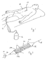
- a balloon catheter in accordance with the present invention is shown and designated 10.
- the balloon catheter 10 is positioned in the vasculature of a patient 12 for the purpose of performing an angioplasty procedure.
- the balloon catheter 10 includes an inflatable balloon 14 and an inflation pump 16 that is connected in fluid communication with the balloon 14. More specifically, activation of the pump 16 by a user causes the balloon 14 to be selectively moved between a deflated configuration and an inflated configuration.
- Fig. 2 shows the balloon 14 in its inflated configuration.
- the balloon 14 of the present invention like typical angioplasty balloons, is elongated and generally defines an axis 18. that extends the length of the balloon 14.
- the balloon 14 also has a surface 20 on which a plurality of elongated blade elements 22 can be mounted.
- the orientation of the blade elements 22 on the surface 20 of balloon 14, and the characteristics of the individual blade elements 22 can be varied to meet the particular requirements and specifications of the user.
- the blade elements 22a, 22b and 22c shown in Fig. 2 are only exemplary.
- a plurality of the blade elements 22 can be axially aligned with each other (e.g. blade elements 22a and 22c).
- the blade elements 22 can be azimuthally distanced from one another (e.g. blade elements 22a and 22b).
- the blade elements 22 can be azimuthally distanced from one another by an angle ⁇ which will preferably position the blade elements 22 uniformly around the axis 18.
- the angle ⁇ may be ninety degrees, one hundred twenty degrees, or one hundred eighty degrees.
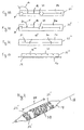
- each blade element 22 preferably includes an elongated main-blade 24 which can be axially oriented on the surface 20. Also, each blade element 22 is mounted on a base member 26 which, in turn, can be mounted on the surface 20 of the balloon 14 in a manner well known in the art, such as by bonding. Thus, all blade elements 22 have several common characteristics. The significant characteristic difference between the various embodiments of the blade elements 22, however, is in the respective grips 28 that are conformed with the main-blade 24.
- a blade element 22 1 has a main-blade 24 that is conformed with a grip 28 1 . More specifically, as shown in Fig. 3A , the grip 28 1 includes a cross-blade 30 that is oriented at an angle ⁇ relative to the main-blade 24.
- the angle ⁇ may vary and may be either greater than or less than ninety degrees. Specifically, for the grip 28 1 shown in Fig. 3A , the angle ⁇ is greater than ninety degrees.
- the angle ⁇ between the main-blade 24 and the cross-blade 30 is substantially equal to ninety degrees. Also, as shown in both Figs.
- the main-blade 24 of blade elements 22 1 or 22 11 can be conformed with a respective grip 28 1 or 28 11 at each end of the main-blade 24.
- a single cross-blade 30 can be positioned substantially midway between the ends of the main-blade 24 as shown in Fig. 3C for the grip 28 111 of a blade element 22 111 .
- the blade element 22 1111 shown in Fig. 3D has a main-blade 24 which is formed with a grip 28 1111 that includes at least one serration along the cutting edge 32 of the main-blade 24.
- all of the respective grips 28 have the common characteristic that they protrude outwardly from the surface 20 of the balloon 14 in a generally radial direction from the axis 18. Furthermore, as they radially protrude from the axis 18, all of the grips 28 present an azimuthally oriented exterior.
- the grips 28 and main-blades 24 are all made of stainless steel.
- the balloon 14 is initially deflated so that its surface 20 is collapsed onto the axis 18.
- the balloon catheter 10, in its deflated configuration is then inserted into the vasculature of the patient 12 to position the balloon 14 at the site of a stenosis (not shown).
- the balloon 14 is then inflated using the inflation pump 16. This causes the surface 20 of the balloon 14 to be radially distanced from the axis 18 to thereby dilate the stenosis and embed the blade element(s) 22 into the stenosis.
- the balloon 14 is deflated and the balloon catheter 10 is removed from the vasculature of the patient 12.
- Important aspects of the present invention are that while the blade element(s) 22 are embeded into the stenosis during an angioplasty procedure, the balloon 14 is effectively held at the site of the stenosis. Specifically, the balloon 14 is prevented from moving either azimuthally in rotation (in the directions of arrows 34, shown in Fig. 2 ), or axially in translation (in the directions of arrows 36 (also shown in Fig. 2 ). More specifically, when the balloon 14 is inflated at the site of the stenosis, azimuthal (rotational) constraints are imposed on the balloon 14 by the axially oriented main-blades 24 of the blade element 22.
- the grip(s) 28 having cross-blades 30 ( Figs. 3A, 3B and 3C ) or serrations in cutting edge 32 ( Fig. 3D ), in combination with the main-blades 24, hold the balloon 14 at the site of a stenosis during an angioplasty procedure. Importantly, this effectively prevents the so-called "watermelon seed" effect noted above.
- a stent 38 can be mounted on the balloon 14.
- the stent 38 needs to be expandable as the balloon 14 is inflated, and the stent 38 should be positioned on the balloon 14 so that the blade elements 22 1 can function as disclosed above.
- Fig. 4 shows the use of a plurality of blade elements 22 1 , it is to be appreciated that as few as one blade element 22 1 can be used.
- each blade element 22 1 be axially aligned with another blade element 22 1 , and that the aligned blade elements 22 1 be separated from each other by a distance 40. Specifically, as shown in Fig. 4 , the distance 40 is established to provide for the positioning of the stent 38 on the balloon.
Abstract
Description
- The present invention pertains generally to devices and methods for performing angioplasty or stent emplacement procedures. More particularly, the present invention pertains to angioplasty balloon catheters that incorporate cutting blades on the surface of the balloon. The present invention is particularly but not exclusively useful as a device and method which incorporates a cutting blade that will anchor the balloon to the stenosis during an angioplasty procedure or the emplacement of a stent in the vasculature of a patient.
- Angioplasty and stent emplacement procedures have been successfully used for many years for the treatment of vasculature diseases. Typically, in an angioplasty procedure, an inflatable balloon is inserted on a catheter into the vasculature and is positioned in a vessel of the vasculature at the site of a stenosis. The balloon is then inflated to dilate the stenosis for improved blood flow through the vessel. Inflatable balloons are also widely used for procedures wherein a stent is to be positioned into the vasculature of a patient.
- In recent years a significantly important advancement has been made in angioplasty procedures with the introduction of the so-called "cutting balloon." More specifically, such a "cutting balloon" incorporates blades which are mounted on the surface of the balloon to cut into a stenosis as the balloon is inflated to dilate the stenosis. For example, such a "cutting balloon" is disclosed and claimed in
U.S. Patent No. 5,797,935 which issued to Barath for an invention entitled "Balloon Activated Force Concentrators for Incising Stenotic Segments" and which is assigned to the same assignee as the present invention. It happens, however, that despite such significant technical advances, the very nature of a particular stenosis can pose additional concerns for consideration. - As is well known, a stenosis in a vessel of the vasculature can be one of many different types and can have various configurations. For instance, some are of a rather slippery consistency. Additionally they may have a configuration that makes it particularly difficult to maintain the position of an angioplasty balloon at the site of the stenosis as the balloon is being inflated. Specifically, it can happen that as the balloon is being inflated, the forces that are generated between the balloon and the stenosis can cause the balloon to be displaced from the site of the stenosis. Obviously, this so-called "watermelon seed" reaction can be disruptive of an angioplasty procedure.
- The above-noted problems are also present, and can be particularly troublesome, in procedures wherein a stent is to be emplaced at a site in the vasculature. As mentioned above, such sites may involve a slippery stenosis that can adversely effect efforts to properly position the stent.
- In light of the above, it is an object of the present invention to provide a system and method for anchoring the inflatable balloon of a balloon catheter to a stenosis in the vasculature of a patient during an angioplasty or stent emplacement procedure. Another object of the present invention is to provide an improved "cutting balloon" catheter which incorporates specifically configured blades that will prevent both axial (translational) and azimuthal (rotational) movements of the balloon relative to the vessel (stenosis site) during an angioplasty procedure. Still another object of the present invention is to provide a system and method for anchoring the balloon of an angioplasty balloon catheter to a stenosis in the vasculature of a patient that is relatively simple to manufacture, is easy to implement, and is comparatively cost effective.
- A system and method for anchoring an angioplasty catheter to a stenosis in the vasculature of a patient requires an elongated inflatable balloon and specially configured blades mounted on the surface of the balloon. More specifically, the balloon defines a longitudinal axis and is mounted on a catheter for selective movement between a deflated configuration and an inflated configuration. In the deflated configuration the surface of the balloon is effectively collapsed onto the axis. In the inflated configuration, however, the surface of the balloon is radially distanced from the axis.
- For the present invention, at least one elongated blade (main-blade) is mounted on the surface of the balloon. Preferably, the main-blade is axially oriented substantially parallel to the axis that is defined by the balloon. Additionally, there is at least one grip that is conformed with the blade. More specifically, the grip is azimuthally oriented on the axis that is defined by the balloon, and it protrudes in a substantially radial direction from the axis of the balloon.
- For one embodiment of the present invention the grip is a serration(s) that is formed into the cutting edge of the main-blade. In another embodiment the grip is a cross-blade that forms an angle α with the blade. In accordance with the present invention this angle α can be ninety degrees, or it may be greater or less than ninety degrees depending on the particular needs of the user. Further, as contemplated for the present invention, the blade and the grip can be made of stainless steel.
- For an alternate embodiment of the present invention the system can include a stent that is to be emplaced in the vasculature of the patient. Specifically, as is well known, the stent is positioned on the balloon for movement with the balloon as the balloon is inflated from its deflated configuration and into its inflated configuration. Thus, the stent can be expanded for emplacement in the vasculature of the patient. Further, when a stent is included in the system of the present invention there can be a plurality of anchoring blades mounted on the balloon. In this case, preferably, each blade is axially aligned with at least one other blade, with a distance therebetween. The stent can then be positioned on the balloon between the blades.
- In operation, as the balloon is inflated into its inflated configuration, the blade and its conformed grip are embedded into the stenosis. This effectively anchors the balloon to the stenosis as the axially oriented main-blade prevents azimuthal (rotational) movement in the vessel relative to said stenosis. At the same time the azimuthally oriented grip prevents axial (translational) movement of the balloon in the vessel relative to the stenosis.
- It is within the contemplation of the present invention that the system will include a plurality of main-blades. Furthermore, it is contemplated that each of the plurality of main-blades may have a plurality of conformed grips. Additionally, some of the plurality of main-blades can be axially aligned with each other. Also, each main-blade can be azimuthally distanced from at least one other main-blade by an angle β. Thus, a series of main-blades can be present in different azimuthal locations on the surface of the balloon.
- The novel features of this invention, as well as the invention itself, both as to its structure and its operation, will be best understood from the accompanying drawings, taken in conjunction with the accompanying description, in which similar reference characters refer to similar parts, and in which:
-
Fig. 1 is a perspective view of a patient undergoing an angioplasty procedure with a balloon catheter that incorporates the present invention; -
Fig. 2 is a perspective view of a preferred embodiment of the present invention; -
Fig. 3A is a top plan view of a blade and grip arrangement in accordance with the present invention; -
Fig. 3B is a top plan view of an alternative blade and grip arrangement in accordance with the present invention; -
Fig. 3C is a top plan view of yet another alternative blade and grip arrangement in accordance with the present invention; -
Fig. 3D is a side elevation view of yet another embodiment of a blade and grip arrangement that is useful for the present invention; and -
Fig. 4 is a perspective view of an alternate embodiment of the present invention showing the incorporation of a stent. - Referring initially to
Fig. 1 , a balloon catheter in accordance with the present invention is shown and designated 10. As shown inFig. 1 , theballoon catheter 10 is positioned in the vasculature of apatient 12 for the purpose of performing an angioplasty procedure. To do this, theballoon catheter 10 includes aninflatable balloon 14 and aninflation pump 16 that is connected in fluid communication with theballoon 14. More specifically, activation of thepump 16 by a user causes theballoon 14 to be selectively moved between a deflated configuration and an inflated configuration. - In more detail,
Fig. 2 shows theballoon 14 in its inflated configuration. In this configuration it can be seen that theballoon 14 of the present invention, like typical angioplasty balloons, is elongated and generally defines anaxis 18. that extends the length of theballoon 14. Theballoon 14 also has asurface 20 on which a plurality ofelongated blade elements 22 can be mounted. In accordance with the present invention, the orientation of theblade elements 22 on thesurface 20 ofballoon 14, and the characteristics of theindividual blade elements 22 can be varied to meet the particular requirements and specifications of the user. Theblade elements Fig. 2 are only exemplary. - For the purposes of the present invention, it is preferable that each
blade element 22, when mounted on thesurface 20 ofballoon 14, be oriented substantially parallel to theaxis 18. Further, as shown inFig. 2 , a plurality of theblade elements 22 can be axially aligned with each other (e.g.blade elements blade elements 22 can be azimuthally distanced from one another (e.g.blade elements 22a and 22b). In particular, theblade elements 22 can be azimuthally distanced from one another by an angle β which will preferably position theblade elements 22 uniformly around theaxis 18. For example, the angle β may be ninety degrees, one hundred twenty degrees, or one hundred eighty degrees. - Variations in the characteristics of the
blade elements 22 will be best appreciated with reference toFigs. 3A, 3B, 3C, and Fig. 3D . In all instances, eachblade element 22 preferably includes an elongated main-blade 24 which can be axially oriented on thesurface 20. Also, eachblade element 22 is mounted on abase member 26 which, in turn, can be mounted on thesurface 20 of theballoon 14 in a manner well known in the art, such as by bonding. Thus, allblade elements 22 have several common characteristics. The significant characteristic difference between the various embodiments of theblade elements 22, however, is in therespective grips 28 that are conformed with the main-blade 24. - For one embodiment of the present invention, a
blade element 221 has a main-blade 24 that is conformed with agrip 281. More specifically, as shown inFig. 3A , thegrip 281 includes a cross-blade 30 that is oriented at an angle α relative to the main-blade 24. The angle α may vary and may be either greater than or less than ninety degrees. Specifically, for thegrip 281 shown inFig. 3A , the angle α is greater than ninety degrees. For thegrip 2811 of theblade element 2211 shown inFig. 3B , however, the angle α between the main-blade 24 and the cross-blade 30 is substantially equal to ninety degrees. Also, as shown in bothFigs. 3A and 3B , the main-blade 24 ofblade elements respective grip blade 24. Alternatively, asingle cross-blade 30 can be positioned substantially midway between the ends of the main-blade 24 as shown inFig. 3C for thegrip 28111 of ablade element 22111. In yet another variation, theblade element 221111 shown inFig. 3D has a main-blade 24 which is formed with agrip 281111 that includes at least one serration along thecutting edge 32 of the main-blade 24. - For the embodiments of the
blade elements respective grips 28 have the common characteristic that they protrude outwardly from thesurface 20 of theballoon 14 in a generally radial direction from theaxis 18. Furthermore, as they radially protrude from theaxis 18, all of thegrips 28 present an azimuthally oriented exterior. Preferably, thegrips 28 and main-blades 24 are all made of stainless steel. - In the operation of the
balloon catheter 10 of the present invention, theballoon 14 is initially deflated so that itssurface 20 is collapsed onto theaxis 18. Theballoon catheter 10, in its deflated configuration, is then inserted into the vasculature of the patient 12 to position theballoon 14 at the site of a stenosis (not shown). Theballoon 14 is then inflated using theinflation pump 16. This causes thesurface 20 of theballoon 14 to be radially distanced from theaxis 18 to thereby dilate the stenosis and embed the blade element(s) 22 into the stenosis. After the stenosis has been dilated, theballoon 14 is deflated and theballoon catheter 10 is removed from the vasculature of thepatient 12. - Important aspects of the present invention are that while the blade element(s) 22 are embeded into the stenosis during an angioplasty procedure, the
balloon 14 is effectively held at the site of the stenosis. Specifically, theballoon 14 is prevented from moving either azimuthally in rotation (in the directions ofarrows 34, shown inFig. 2 ), or axially in translation (in the directions of arrows 36 (also shown inFig. 2 ). More specifically, when theballoon 14 is inflated at the site of the stenosis, azimuthal (rotational) constraints are imposed on theballoon 14 by the axially oriented main-blades 24 of theblade element 22. At the same time, axial (translational) constraints are imposed on theballoon 14 by azimuthally oriented components of the grip(s) 28. Thus, the grip(s) 28, having cross-blades 30 (Figs. 3A, 3B and 3C ) or serrations in cutting edge 32 (Fig. 3D ), in combination with the main-blades 24, hold theballoon 14 at the site of a stenosis during an angioplasty procedure. Importantly, this effectively prevents the so-called "watermelon seed" effect noted above. - For an alternate embodiment of the present invention, as shown in
Fig. 4 , astent 38, of any type well known in the pertinent art, can be mounted on theballoon 14. For purposes of the present invention, thestent 38 needs to be expandable as theballoon 14 is inflated, and thestent 38 should be positioned on theballoon 14 so that theblade elements 221 can function as disclosed above. AlthoughFig. 4 shows the use of a plurality ofblade elements 221, it is to be appreciated that as few as oneblade element 221 can be used. When a plurality ofblade elements 221 are used, however, it is preferable that eachblade element 221 be axially aligned with anotherblade element 221, and that the alignedblade elements 221 be separated from each other by adistance 40. Specifically, as shown inFig. 4 , thedistance 40 is established to provide for the positioning of thestent 38 on the balloon. - While the particular Balloon Anchoring System as herein shown and disclosed in detail is fully capable of obtaining the objects and providing the advantages herein before stated, it is to be understood that it is merely illustrative of the presently preferred embodiments of the invention and that no limitations are intended to the details of construction or design herein shown other than as described in the appended claims.
Claims (11)
- A system for anchoring an angioplasty catheter (10) to a stenosis in the vasculature of a patient which comprises:an elongated inflatable balloon (14) having a surface (20) and defining a longitudinal axis (18), said balloon being mounted on said catheter for selective movement between a deflated configuration wherein said surface of said balloon is collapsed on said axis, and an inflated configuration wherein said surface is radially distanced from said axis;at least one elongated blade (24) mounted on said surface of said balloon substantially parallel to said axis of said balloon;characterised in that it further comprises:at least one azimuthally oriented cross-blade grip (28) conformed with said blade (24), said grip being oriented to protrude in a substantially radial direction from said axis (18); anda means (16) for inflating said balloon into said inflated configuration to embed said blade (24) and said grip (28) into said stenosis to anchor said balloon thereto by respectively preventing azimuthal and axial movements of said balloon relative to said stenosis.
- A system as recited in claim 1 further comprising a stent (38) positioned on said balloon (14) for movement therewith from said deflated configuration into said inflated configuration to expand said stent for emplacement in the vasculature of the patient.
- A system as recited in claim 2 further comprising a plurality of said blades (24), with each said blade axially aligned with at least one other said blade, and with a distance therebetween for positioning said stent therebetween on said balloon.
- A system as recited in any preceding claim, wherein the elongated blade has a sharp cutting edge (32).
- A system as claimed in any preceding claim, wherein the cross-blade grip (28) has a sharp cutting edge.
- A system as claimed in any preceding claim, wherein said cross-blade grip (28) forms an angle α with said blade.
- A system as claimed in claim 7, wherein said angle α is ninety degrees.
- A system as claimed in any preceding claim, wherein said blade (24) and said grip (28) are made of stainless steel.
- A system as claimed in claim 1, wherein there are a plurality of said blades (24), and further wherein each said blade has a plurality of conformed grips (28).
- A system as claimed in claim 1, wherein a plurality of said blades (24) are axially aligned with each other.
- A system as claimed in claim 1, wherein there are a plurality of said blades (24), and further wherein each said blade is azimuthally distanced from at least one other said blade by an angle β.
Applications Claiming Priority (3)
| Application Number | Priority Date | Filing Date | Title |
|---|---|---|---|
| US927135 | 2001-08-10 | ||
| US09/927,135 US6562062B2 (en) | 2001-08-10 | 2001-08-10 | Balloon anchoring system |
| PCT/US2002/010724 WO2003013393A1 (en) | 2001-08-10 | 2002-04-04 | Balloon anchoring system |
Publications (3)
| Publication Number | Publication Date |
|---|---|
| EP1414373A1 EP1414373A1 (en) | 2004-05-06 |
| EP1414373A4 EP1414373A4 (en) | 2005-09-21 |
| EP1414373B1 true EP1414373B1 (en) | 2008-05-07 |
Family
ID=25454242
Family Applications (1)
| Application Number | Title | Priority Date | Filing Date |
|---|---|---|---|
| EP02726706A Expired - Lifetime EP1414373B1 (en) | 2001-08-10 | 2002-04-04 | Balloon anchoring system |
Country Status (8)
| Country | Link |
|---|---|
| US (1) | US6562062B2 (en) |
| EP (1) | EP1414373B1 (en) |
| JP (1) | JP2004537369A (en) |
| AT (1) | ATE394079T1 (en) |
| CA (1) | CA2452828A1 (en) |
| DE (1) | DE60226448D1 (en) |
| ES (1) | ES2307748T3 (en) |
| WO (1) | WO2003013393A1 (en) |
Cited By (7)
| Publication number | Priority date | Publication date | Assignee | Title |
|---|---|---|---|---|
| US9173977B2 (en) | 2010-04-19 | 2015-11-03 | Angioscore, Inc. | Coating formulations for scoring or cutting balloon catheters |
| US9351756B2 (en) | 2010-09-21 | 2016-05-31 | Angioscore, Inc. | Method and system for treating valve stenosis |
| US9375328B2 (en) | 2001-11-09 | 2016-06-28 | Angioscore, Inc. | Balloon catheter with non-deployable stent |
| US9586031B2 (en) | 2005-05-11 | 2017-03-07 | Angioscore, Inc. | Methods and systems for delivering substances into luminal walls |
| US9962529B2 (en) | 2003-01-21 | 2018-05-08 | Angioscore, Inc. | Apparatus and methods for treating hardened vascular lesions |
| US10086178B2 (en) | 2001-11-09 | 2018-10-02 | Angioscore, Inc. | Balloon catheter with non-deployable stent |
| US10117668B2 (en) | 2013-10-08 | 2018-11-06 | The Spectranetics Corporation | Balloon catheter with non-deployable stent having improved stability |
Families Citing this family (47)
| Publication number | Priority date | Publication date | Assignee | Title |
|---|---|---|---|---|
| US8061006B2 (en) * | 2001-07-26 | 2011-11-22 | Powderject Research Limited | Particle cassette, method and kit therefor |
| US6632231B2 (en) * | 2001-08-23 | 2003-10-14 | Scimed Life Systems, Inc. | Segmented balloon catheter blade |
| US20030144683A1 (en) * | 2001-12-13 | 2003-07-31 | Avantec Vascular Corporation | Inflatable members having concentrated force regions |
| US7686824B2 (en) | 2003-01-21 | 2010-03-30 | Angioscore, Inc. | Apparatus and methods for treating hardened vascular lesions |
| US20050021070A1 (en) * | 2003-01-21 | 2005-01-27 | Angioscore, Inc. | Methods and apparatus for manipulating vascular prostheses |
| US7279002B2 (en) * | 2003-04-25 | 2007-10-09 | Boston Scientific Scimed, Inc. | Cutting stent and balloon |
| US7632288B2 (en) * | 2003-05-12 | 2009-12-15 | Boston Scientific Scimed, Inc. | Cutting balloon catheter with improved pushability |
| US7758604B2 (en) * | 2003-05-29 | 2010-07-20 | Boston Scientific Scimed, Inc. | Cutting balloon catheter with improved balloon configuration |
| US7008438B2 (en) * | 2003-07-14 | 2006-03-07 | Scimed Life Systems, Inc. | Anchored PTCA balloon |
| US6921269B2 (en) * | 2003-07-30 | 2005-07-26 | Honeywell International Inc. | Relative rotation signal transfer assembly |
| US7273471B1 (en) | 2003-12-23 | 2007-09-25 | Advanced Cardiovascular Systems, Inc. | Catheter balloon having a porous layer with ridges |
| US7270673B2 (en) * | 2003-12-31 | 2007-09-18 | Boston Scientific Scimed, Inc. | Microsurgical balloon with protective reinforcement |
| US7316709B2 (en) * | 2004-01-13 | 2008-01-08 | Advanced Cardiovascular Systems, Inc. | Balloon catheter having a textured member for enhancing balloon or stent retention |
| US20050177130A1 (en) * | 2004-02-10 | 2005-08-11 | Angioscore, Inc. | Balloon catheter with spiral folds |
| US7754047B2 (en) * | 2004-04-08 | 2010-07-13 | Boston Scientific Scimed, Inc. | Cutting balloon catheter and method for blade mounting |
| US7566319B2 (en) | 2004-04-21 | 2009-07-28 | Boston Scientific Scimed, Inc. | Traction balloon |
| US20050240148A1 (en) * | 2004-04-21 | 2005-10-27 | Scimed Life Systems, Inc. | Traction cutting balloon |
| US7976557B2 (en) * | 2004-06-23 | 2011-07-12 | Boston Scientific Scimed, Inc. | Cutting balloon and process |
| US20060079845A1 (en) * | 2004-10-08 | 2006-04-13 | Eben Howard And Pamela A. Howard | Movable inflatable anchor for medical devices |
| US20060079838A1 (en) * | 2004-10-08 | 2006-04-13 | Walker Steven C | Movable Balloon anchor for medical devices |
| US7291158B2 (en) * | 2004-11-12 | 2007-11-06 | Boston Scientific Scimed, Inc. | Cutting balloon catheter having a segmented blade |
| US8038691B2 (en) | 2004-11-12 | 2011-10-18 | Boston Scientific Scimed, Inc. | Cutting balloon catheter having flexible atherotomes |
| US8066726B2 (en) * | 2004-11-23 | 2011-11-29 | Boston Scientific Scimed, Inc. | Serpentine cutting blade for cutting balloon |
| US20060184191A1 (en) * | 2005-02-11 | 2006-08-17 | Boston Scientific Scimed, Inc. | Cutting balloon catheter having increased flexibility regions |
| US20060247674A1 (en) * | 2005-04-29 | 2006-11-02 | Roman Ricardo D | String cutting balloon |
| US20070198047A1 (en) * | 2005-12-20 | 2007-08-23 | Medical Components, Inc. | Cutting balloon catheter assembly |
| US20080077164A1 (en) * | 2006-02-24 | 2008-03-27 | National University Of Ireland, Galway | Minimally Invasive Intravascular Treatment Device |
| US20090105687A1 (en) * | 2007-10-05 | 2009-04-23 | Angioscore, Inc. | Scoring catheter with drug delivery membrane |
| US11219750B2 (en) | 2008-03-21 | 2022-01-11 | Cagent Vascular, Inc. | System and method for plaque serration |
| JP5846905B2 (en) | 2008-03-21 | 2016-01-20 | ケイジェント ヴァスキュラー, エルエルシーCagent Vascular, Llc | Intravascular device for perforation and serration of atherosclerotic plaques in blood vessels |
| US9480826B2 (en) | 2008-03-21 | 2016-11-01 | Cagent Vascular, Llc | Intravascular device |
| US20100286593A1 (en) * | 2009-05-11 | 2010-11-11 | Hotspur Technologies, Inc. | Balloon catheter with cutting features and methods for use |
| US20110112623A1 (en) * | 2009-11-10 | 2011-05-12 | Schatz Richard A | System and Method for Placing a Coronary Stent at the Ostium of a Blood Vessel |
| EP2566562A1 (en) | 2010-05-07 | 2013-03-13 | Cook Medical Technologies LLC | Balloon with integral segmented dilation elements |
| US8491615B2 (en) | 2010-12-29 | 2013-07-23 | Boston Scientific Scimed, Inc. | Cutting balloon catheter |
| GB2487400B (en) * | 2011-01-20 | 2013-07-10 | Cook Medical Technologies Llc | Scoring balloon with offset scoring elements |
| EP3824829A1 (en) | 2011-07-15 | 2021-05-26 | Boston Scientific Scimed Inc. | Cutting balloon catheter with flexible cutting blades |
| WO2015114463A2 (en) | 2014-02-02 | 2015-08-06 | Gil Hefer | Apparatus and methods for recannalization, valve repair and replacement |
| US10463842B2 (en) | 2014-06-04 | 2019-11-05 | Cagent Vascular, Llc | Cage for medical balloon |
| EP3215212B1 (en) | 2014-11-03 | 2020-07-29 | Cagent Vascular, LLC | Serration balloon |
| WO2016090122A1 (en) | 2014-12-03 | 2016-06-09 | PAVmed Inc. | Systems and methods for percutaneous division of fibrous structures |
| US10166374B2 (en) | 2015-09-17 | 2019-01-01 | Cagent Vascular, Llc | Wedge dissectors for a medical balloon |
| CN110114108B (en) | 2016-11-16 | 2022-12-06 | 开金血管公司 | System and method for depositing a drug into tissue through teeth |
| US11051845B2 (en) * | 2017-01-14 | 2021-07-06 | Choon Kee Lee | Non-surgical chest tube introducer |
| EP4295892A3 (en) | 2018-04-09 | 2024-03-06 | Boston Scientific Scimed, Inc. | Cutting balloon catheter |
| WO2020023749A1 (en) | 2018-07-25 | 2020-01-30 | Cagent Vascular, Llc | Medical balloon catheters with enhanced pushability |
| US11812987B2 (en) | 2019-11-27 | 2023-11-14 | Boston Scientific Scimed, Inc. | Cutting balloon catheter |
Family Cites Families (14)
| Publication number | Priority date | Publication date | Assignee | Title |
|---|---|---|---|---|
| US4307722A (en) | 1979-08-14 | 1981-12-29 | Evans Joseph M | Dilators for arterial dilation |
| US4273128A (en) | 1980-01-14 | 1981-06-16 | Lary Banning G | Coronary cutting and dilating instrument |
| US4921483A (en) | 1985-12-19 | 1990-05-01 | Leocor, Inc. | Angioplasty catheter |
| US4793348A (en) | 1986-11-15 | 1988-12-27 | Palmaz Julio C | Balloon expandable vena cava filter to prevent migration of lower extremity venous clots into the pulmonary circulation |
| US4921484A (en) | 1988-07-25 | 1990-05-01 | Cordis Corporation | Mesh balloon catheter device |
| US5009659A (en) | 1989-10-30 | 1991-04-23 | Schneider (Usa) Inc. | Fiber tip atherectomy catheter |
| US5196024A (en) | 1990-07-03 | 1993-03-23 | Cedars-Sinai Medical Center | Balloon catheter with cutting edge |
| US5320634A (en) * | 1990-07-03 | 1994-06-14 | Interventional Technologies, Inc. | Balloon catheter with seated cutting edges |
| US5395331A (en) * | 1992-04-27 | 1995-03-07 | Minnesota Mining And Manufacturing Company | Retrograde coronary sinus catheter having a ribbed balloon |
| US5176693A (en) | 1992-05-11 | 1993-01-05 | Interventional Technologies, Inc. | Balloon expandable atherectomy cutter |
| CA2118886C (en) * | 1993-05-07 | 1998-12-08 | Dennis Vigil | Method and apparatus for dilatation of a stenotic vessel |
| US5797935A (en) * | 1996-09-26 | 1998-08-25 | Interventional Technologies Inc. | Balloon activated forced concentrators for incising stenotic segments |
| WO1999018864A1 (en) * | 1997-10-10 | 1999-04-22 | Hearten Medical, Inc. | A balloon catheter for abrading a patent foramen ovale and method of using the balloon catheter |
| EP1305078B1 (en) * | 2000-07-24 | 2011-06-29 | Jeffrey Grayzel | Stiffened balloon catheter for dilatation and stenting |
-
2001
- 2001-08-10 US US09/927,135 patent/US6562062B2/en not_active Expired - Lifetime
-
2002
- 2002-04-04 CA CA002452828A patent/CA2452828A1/en not_active Abandoned
- 2002-04-04 ES ES02726706T patent/ES2307748T3/en not_active Expired - Lifetime
- 2002-04-04 DE DE60226448T patent/DE60226448D1/en not_active Expired - Lifetime
- 2002-04-04 JP JP2003518409A patent/JP2004537369A/en active Pending
- 2002-04-04 AT AT02726706T patent/ATE394079T1/en not_active IP Right Cessation
- 2002-04-04 EP EP02726706A patent/EP1414373B1/en not_active Expired - Lifetime
- 2002-04-04 WO PCT/US2002/010724 patent/WO2003013393A1/en active Application Filing
Cited By (16)
| Publication number | Priority date | Publication date | Assignee | Title |
|---|---|---|---|---|
| US11571554B2 (en) | 2001-11-09 | 2023-02-07 | Angioscore, Inc. | Balloon catheter with non-deployable stent |
| US9375328B2 (en) | 2001-11-09 | 2016-06-28 | Angioscore, Inc. | Balloon catheter with non-deployable stent |
| US10086178B2 (en) | 2001-11-09 | 2018-10-02 | Angioscore, Inc. | Balloon catheter with non-deployable stent |
| US9962529B2 (en) | 2003-01-21 | 2018-05-08 | Angioscore, Inc. | Apparatus and methods for treating hardened vascular lesions |
| US10722694B2 (en) | 2003-01-21 | 2020-07-28 | Angioscore, Inc. | Apparatus and methods for treating hardened vascular lesions |
| US9586031B2 (en) | 2005-05-11 | 2017-03-07 | Angioscore, Inc. | Methods and systems for delivering substances into luminal walls |
| US10076641B2 (en) | 2005-05-11 | 2018-09-18 | The Spectranetics Corporation | Methods and systems for delivering substances into luminal walls |
| US11420030B2 (en) | 2005-05-11 | 2022-08-23 | Angioscore, Inc. | Methods and systems for delivering substances into luminal walls |
| US9173977B2 (en) | 2010-04-19 | 2015-11-03 | Angioscore, Inc. | Coating formulations for scoring or cutting balloon catheters |
| US10314947B2 (en) | 2010-04-19 | 2019-06-11 | Angioscore, Inc. | Coating formulations for scoring or cutting balloon catheters |
| US10471184B2 (en) | 2010-04-19 | 2019-11-12 | Angioscore, Inc. | Coating formulations for scoring or cutting balloon catheters |
| US9364254B2 (en) | 2010-09-21 | 2016-06-14 | Angioscore, Inc. | Method and system for treating valve stenosis |
| US10736652B2 (en) | 2010-09-21 | 2020-08-11 | Angioscore, Inc. | Method and system for treating valve stenosis |
| US9351756B2 (en) | 2010-09-21 | 2016-05-31 | Angioscore, Inc. | Method and system for treating valve stenosis |
| US10117668B2 (en) | 2013-10-08 | 2018-11-06 | The Spectranetics Corporation | Balloon catheter with non-deployable stent having improved stability |
| US10485571B2 (en) | 2013-10-08 | 2019-11-26 | Angioscore, Inc. | Balloon catheter with non-deployable stent having improved stability |
Also Published As
| Publication number | Publication date |
|---|---|
| US20030032973A1 (en) | 2003-02-13 |
| US6562062B2 (en) | 2003-05-13 |
| CA2452828A1 (en) | 2003-02-20 |
| JP2004537369A (en) | 2004-12-16 |
| EP1414373A1 (en) | 2004-05-06 |
| ES2307748T3 (en) | 2008-12-01 |
| DE60226448D1 (en) | 2008-06-19 |
| EP1414373A4 (en) | 2005-09-21 |
| WO2003013393A1 (en) | 2003-02-20 |
| ATE394079T1 (en) | 2008-05-15 |
Similar Documents
| Publication | Publication Date | Title |
|---|---|---|
| EP1414373B1 (en) | Balloon anchoring system | |
| JP5123160B2 (en) | Balloon catheter and method for providing a channel in a lesion | |
| US7029483B2 (en) | Device for percutaneous cutting and dilating a stenosis of the aortic valve | |
| EP1740105B1 (en) | Apparatus for treating hardened vascular lesions | |
| US7008438B2 (en) | Anchored PTCA balloon | |
| EP1587447B1 (en) | Retrieval device | |
| US5713913A (en) | Device and method for transecting a coronary artery | |
| US7691119B2 (en) | Balloon catheter with non-deployable stent | |
| US7955350B2 (en) | Apparatus and methods for treating hardened vascular lesions | |
| US6520984B1 (en) | Stent graft assembly and method | |
| US8048093B2 (en) | Textured balloons | |
| US20030144677A1 (en) | Reciprocating cutting and dilating balloon | |
| EP1258230A2 (en) | Balloon catheter device | |
| CA2416825A1 (en) | Stiffened balloon catheter for dilatation and stenting | |
| EP3600090B1 (en) | Tissue-removing catheter with abrasive burr having portion free from abrasive exterior surface | |
| US20030144578A1 (en) | Anastomosis anchoring device and method | |
| US20210177454A1 (en) | Catheter with radially expandable scoring element | |
| US20210346034A1 (en) | Device for closing a vein juncture in the treatment of varicose veins |
Legal Events
| Date | Code | Title | Description |
|---|---|---|---|
| PUAI | Public reference made under article 153(3) epc to a published international application that has entered the european phase |
Free format text: ORIGINAL CODE: 0009012 |
|
| 17P | Request for examination filed |
Effective date: 20040202 |
|
| AK | Designated contracting states |
Kind code of ref document: A1 Designated state(s): AT BE CH CY DE DK ES FI FR GB GR IE IT LI LU MC NL PT SE TR |
|
| AX | Request for extension of the european patent |
Extension state: AL LT LV MK RO SI |
|
| A4 | Supplementary search report drawn up and despatched |
Effective date: 20050804 |
|
| RIC1 | Information provided on ipc code assigned before grant |
Ipc: 7A 61F 2/06 A Ipc: 7A 61B 17/22 B Ipc: 7A 61M 29/02 B |
|
| RAP1 | Party data changed (applicant data changed or rights of an application transferred) |
Owner name: BOSTON SCIENTIFIC SCIMED, INC. |
|
| 17Q | First examination report despatched |
Effective date: 20070308 |
|
| GRAP | Despatch of communication of intention to grant a patent |
Free format text: ORIGINAL CODE: EPIDOSNIGR1 |
|
| GRAS | Grant fee paid |
Free format text: ORIGINAL CODE: EPIDOSNIGR3 |
|
| GRAA | (expected) grant |
Free format text: ORIGINAL CODE: 0009210 |
|
| AK | Designated contracting states |
Kind code of ref document: B1 Designated state(s): AT BE CH CY DE DK ES FI FR GB GR IE IT LI LU MC NL PT SE TR |
|
| REG | Reference to a national code |
Ref country code: GB Ref legal event code: FG4D |
|
| REG | Reference to a national code |
Ref country code: CH Ref legal event code: EP |
|
| REG | Reference to a national code |
Ref country code: IE Ref legal event code: FG4D Free format text: LANGUAGE OF EP DOCUMENT: FRENCH |
|
| REF | Corresponds to: |
Ref document number: 60226448 Country of ref document: DE Date of ref document: 20080619 Kind code of ref document: P |
|
| PG25 | Lapsed in a contracting state [announced via postgrant information from national office to epo] |
Ref country code: FI Free format text: LAPSE BECAUSE OF FAILURE TO SUBMIT A TRANSLATION OF THE DESCRIPTION OR TO PAY THE FEE WITHIN THE PRESCRIBED TIME-LIMIT Effective date: 20080507 |
|
| PG25 | Lapsed in a contracting state [announced via postgrant information from national office to epo] |
Ref country code: AT Free format text: LAPSE BECAUSE OF FAILURE TO SUBMIT A TRANSLATION OF THE DESCRIPTION OR TO PAY THE FEE WITHIN THE PRESCRIBED TIME-LIMIT Effective date: 20080507 |
|
| REG | Reference to a national code |
Ref country code: ES Ref legal event code: FG2A Ref document number: 2307748 Country of ref document: ES Kind code of ref document: T3 |
|
| PG25 | Lapsed in a contracting state [announced via postgrant information from national office to epo] |
Ref country code: SE Free format text: LAPSE BECAUSE OF FAILURE TO SUBMIT A TRANSLATION OF THE DESCRIPTION OR TO PAY THE FEE WITHIN THE PRESCRIBED TIME-LIMIT Effective date: 20080807 Ref country code: PT Free format text: LAPSE BECAUSE OF FAILURE TO SUBMIT A TRANSLATION OF THE DESCRIPTION OR TO PAY THE FEE WITHIN THE PRESCRIBED TIME-LIMIT Effective date: 20081007 Ref country code: DK Free format text: LAPSE BECAUSE OF FAILURE TO SUBMIT A TRANSLATION OF THE DESCRIPTION OR TO PAY THE FEE WITHIN THE PRESCRIBED TIME-LIMIT Effective date: 20080507 |
|
| PG25 | Lapsed in a contracting state [announced via postgrant information from national office to epo] |
Ref country code: BE Free format text: LAPSE BECAUSE OF FAILURE TO SUBMIT A TRANSLATION OF THE DESCRIPTION OR TO PAY THE FEE WITHIN THE PRESCRIBED TIME-LIMIT Effective date: 20080507 |
|
| PLBE | No opposition filed within time limit |
Free format text: ORIGINAL CODE: 0009261 |
|
| STAA | Information on the status of an ep patent application or granted ep patent |
Free format text: STATUS: NO OPPOSITION FILED WITHIN TIME LIMIT |
|
| 26N | No opposition filed |
Effective date: 20090210 |
|
| REG | Reference to a national code |
Ref country code: CH Ref legal event code: PL |
|
| PG25 | Lapsed in a contracting state [announced via postgrant information from national office to epo] |
Ref country code: LI Free format text: LAPSE BECAUSE OF NON-PAYMENT OF DUE FEES Effective date: 20090430 Ref country code: CH Free format text: LAPSE BECAUSE OF NON-PAYMENT OF DUE FEES Effective date: 20090430 |
|
| PG25 | Lapsed in a contracting state [announced via postgrant information from national office to epo] |
Ref country code: MC Free format text: LAPSE BECAUSE OF NON-PAYMENT OF DUE FEES Effective date: 20090430 |
|
| PGFP | Annual fee paid to national office [announced via postgrant information from national office to epo] |
Ref country code: IE Payment date: 20100319 Year of fee payment: 9 |
|
| PGFP | Annual fee paid to national office [announced via postgrant information from national office to epo] |
Ref country code: GB Payment date: 20100312 Year of fee payment: 9 |
|
| PGFP | Annual fee paid to national office [announced via postgrant information from national office to epo] |
Ref country code: ES Payment date: 20100420 Year of fee payment: 9 Ref country code: FR Payment date: 20100420 Year of fee payment: 9 |
|
| PGFP | Annual fee paid to national office [announced via postgrant information from national office to epo] |
Ref country code: DE Payment date: 20100430 Year of fee payment: 9 Ref country code: IT Payment date: 20100422 Year of fee payment: 9 Ref country code: NL Payment date: 20100412 Year of fee payment: 9 |
|
| PG25 | Lapsed in a contracting state [announced via postgrant information from national office to epo] |
Ref country code: GR Free format text: LAPSE BECAUSE OF FAILURE TO SUBMIT A TRANSLATION OF THE DESCRIPTION OR TO PAY THE FEE WITHIN THE PRESCRIBED TIME-LIMIT Effective date: 20080808 |
|
| PG25 | Lapsed in a contracting state [announced via postgrant information from national office to epo] |
Ref country code: LU Free format text: LAPSE BECAUSE OF NON-PAYMENT OF DUE FEES Effective date: 20090404 |
|
| PG25 | Lapsed in a contracting state [announced via postgrant information from national office to epo] |
Ref country code: TR Free format text: LAPSE BECAUSE OF FAILURE TO SUBMIT A TRANSLATION OF THE DESCRIPTION OR TO PAY THE FEE WITHIN THE PRESCRIBED TIME-LIMIT Effective date: 20080507 |
|
| PG25 | Lapsed in a contracting state [announced via postgrant information from national office to epo] |
Ref country code: CY Free format text: LAPSE BECAUSE OF FAILURE TO SUBMIT A TRANSLATION OF THE DESCRIPTION OR TO PAY THE FEE WITHIN THE PRESCRIBED TIME-LIMIT Effective date: 20080507 |
|
| REG | Reference to a national code |
Ref country code: NL Ref legal event code: V1 Effective date: 20111101 |
|
| GBPC | Gb: european patent ceased through non-payment of renewal fee |
Effective date: 20110404 |
|
| REG | Reference to a national code |
Ref country code: FR Ref legal event code: ST Effective date: 20111230 |
|
| PG25 | Lapsed in a contracting state [announced via postgrant information from national office to epo] |
Ref country code: DE Free format text: LAPSE BECAUSE OF NON-PAYMENT OF DUE FEES Effective date: 20111101 Ref country code: FR Free format text: LAPSE BECAUSE OF NON-PAYMENT OF DUE FEES Effective date: 20110502 Ref country code: NL Free format text: LAPSE BECAUSE OF NON-PAYMENT OF DUE FEES Effective date: 20111101 |
|
| REG | Reference to a national code |
Ref country code: IE Ref legal event code: MM4A |
|
| REG | Reference to a national code |
Ref country code: DE Ref legal event code: R119 Ref document number: 60226448 Country of ref document: DE Effective date: 20111101 |
|
| PG25 | Lapsed in a contracting state [announced via postgrant information from national office to epo] |
Ref country code: IT Free format text: LAPSE BECAUSE OF NON-PAYMENT OF DUE FEES Effective date: 20110404 Ref country code: GB Free format text: LAPSE BECAUSE OF NON-PAYMENT OF DUE FEES Effective date: 20110404 |
|
| PG25 | Lapsed in a contracting state [announced via postgrant information from national office to epo] |
Ref country code: IE Free format text: LAPSE BECAUSE OF NON-PAYMENT OF DUE FEES Effective date: 20110404 |
|
| REG | Reference to a national code |
Ref country code: ES Ref legal event code: FD2A Effective date: 20131030 |
|
| PG25 | Lapsed in a contracting state [announced via postgrant information from national office to epo] |
Ref country code: ES Free format text: LAPSE BECAUSE OF NON-PAYMENT OF DUE FEES Effective date: 20110405 |