EP1409185B1 - Thread former or tap - Google Patents
Thread former or tap Download PDFInfo
- Publication number
- EP1409185B1 EP1409185B1 EP02764705A EP02764705A EP1409185B1 EP 1409185 B1 EP1409185 B1 EP 1409185B1 EP 02764705 A EP02764705 A EP 02764705A EP 02764705 A EP02764705 A EP 02764705A EP 1409185 B1 EP1409185 B1 EP 1409185B1
- Authority
- EP
- European Patent Office
- Prior art keywords
- shaft
- profile element
- tap
- thread forming
- screw
- Prior art date
- Legal status (The legal status is an assumption and is not a legal conclusion. Google has not performed a legal analysis and makes no representation as to the accuracy of the status listed.)
- Expired - Lifetime
Links
Images

Classifications
-
- B—PERFORMING OPERATIONS; TRANSPORTING
- B23—MACHINE TOOLS; METAL-WORKING NOT OTHERWISE PROVIDED FOR
- B23G—THREAD CUTTING; WORKING OF SCREWS, BOLT HEADS, OR NUTS, IN CONJUNCTION THEREWITH
- B23G7/00—Forming thread by means of tools similar both in form and in manner of use to thread-cutting tools, but without removing any material
- B23G7/02—Tools for this purpose
-
- B—PERFORMING OPERATIONS; TRANSPORTING
- B23—MACHINE TOOLS; METAL-WORKING NOT OTHERWISE PROVIDED FOR
- B23G—THREAD CUTTING; WORKING OF SCREWS, BOLT HEADS, OR NUTS, IN CONJUNCTION THEREWITH
- B23G5/00—Thread-cutting tools; Die-heads
- B23G5/02—Thread-cutting tools; Die-heads without means for adjustment
- B23G5/06—Taps
-
- B—PERFORMING OPERATIONS; TRANSPORTING
- B23—MACHINE TOOLS; METAL-WORKING NOT OTHERWISE PROVIDED FOR
- B23G—THREAD CUTTING; WORKING OF SCREWS, BOLT HEADS, OR NUTS, IN CONJUNCTION THEREWITH
- B23G2200/00—Details of threading tools
- B23G2200/02—Tools in which the shank and the cutting part are made from different materials or from separate components
Definitions
- the invention relates to a thread former or drill according to the preamble of Patent claim 1.
- a thread former is from document GB-A-1209196.
- Thread formers are also geometrically from a bolt derived. However, they do not chop up a material, but merely displace it. The Workpiece is therefore pre-drilled with the mean flank diameter. Of the Thread former has at the top a rising profile, which is the material increasingly displaced.
- a thread former has become known with a cylindrical Clamping shank and a shaping area deviating from the circular shape, polygonal cross section and with the thread to be produced corresponding thread furrows on the outer circumference.
- corners of the shaping area are cylindrical strips of particularly hard and wear-resistant material soldered into corresponding, axially extending grooves, which have a thread grooves adapted profiling on the outer circumference.
- Taps have the same thread profile as taps However, in their profile section a polygonal cross-section with, for example three or six "corners".
- the profile section of thread formers and drills has a first forming Area on which essentially the thread is made and a subsequent leadership section. This serves to guide the tool when Turn back from the hole after completion of the internal thread.
- Thread formers and drills are relatively expensive to manufacture and are under Circumstances of a high quality material. After wear or damage the tool is no longer usable.
- the invention has for its object to a thread former or drill to create that produced with a lesser amount of material and manufacturing can be.
- the forming or cutting profile section is as formed separate profile element that except an inlet or gate taper has at least two full profiles and by means of a fastening device can be mounted centric and non-rotatable on the shaft.
- the profile element may be plate-shaped, or have a short axial length; except the inlet or gate cone, it has relatively few full profiles on, for example two to four.
- the shank for the tool according to the invention can in a conventional manner and conventional dimensions of a highly resilient material, in particular be made of a suitable steel. He needs wear of the profile element not to be thrown away, but can be reused frequently.
- the invention also makes it possible to provide a plurality of different ones Profile elements with different diameter, different pitch and so on, which can each be connected to a unified body.
- the profile element therefore only needs to consist of a suitable hard material. As a result, the material usage is significantly lower than with conventional Tools.
- the projections and depressions have complementary lateral to the axis of the Shank or the profile element inclined surfaces, for the purpose of centering and torque transmission engaged. These surfaces can plan or be formed spherical. Preferably, only the mentioned surfaces are engaged, which means that the end faces of profile element and shank a distance have each other when the profile element is attached to the shaft.
- the surfaces are formed on ribs or grooves which are crosswise are arranged radially, with the center of the cross on the axis of Shank or the profile element is located.
- the edges of the ribs and grooves may have a chamfer.
- the profile element can be a hard metal, but also high-speed steel, Ceramic, or other known material used. It understands itself, that the outer diameter of the shaft at the thread former, at least must be slightly smaller than the core diameter of the thread to be created.
- shank can certainly be used for profile elements for producing different Thread sizes are used.
- an attachment of the separate profile element on the shaft there are various possibilities conceivable, an attachment of the separate profile element on the shaft.
- the profile element by means of a screw in an axial Tapped hole is attached to the shaft.
- the profile element has accordingly a central bore, wherein the screw z.
- B. a conical section having, with a conical countersinking of the bore of the profile element interacts. The screw makes no contribution to torque transmission from the shaft to the workpiece.
- a threaded stem may be formed on the stem, either with a threaded bore of the profile element cooperates, or it is a nut provided, which is screwed onto the pin for attachment of the profile element on the shaft.
- the profile element can also be soldered to the shaft. In this case is However, the interchangeability makes it difficult, since the profile element is heated first must when it should be removed from the shaft.
- a single profile element is centric on Shaft attached.
- Another solution according to the invention provides that two or more identical plate-shaped separate shape profiles on the front side of the shaft be fastened non-rotatably.
- the shape profiles have as well as the above described profiles in the sections projecting beyond the shaft Threaded profiles on to produce the internal thread.
- Such a tool is a thread rolling tool comparable to the creation of internal thread with the Exception that in the invention, the "roles" non-rotatably attached to the shaft are.
- the last tool described is especially suitable as a mold.
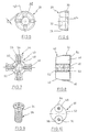
- a Werhzeugschaft 10 is shown, which at one end a clamping section 12 and at the other end a portion 14 for connection with a profile element according to FIG. 4. From the end view of the shaft 10 according to FIG Fig. 2 it can be seen that it has a central threaded bore 16 and cross-shaped arranged ribs 24, wherein the cross of the ribs 24 in its center coincides with the axis of the shaft 10 and the bore 16.
- a plate-shaped shape profile element 20 is shown, which at its Circumference has a Anformkegel and a thread profile (not shown) for Production of an internal thread according to the thread-forming or -formhabilit.
- the circumference of the shape profile element 20 is polygonal, which is not shown in FIG. 4 is. With regard to further details of the profile element 20 is still in connection with the Fign. 5 and 6 received.
- the profile element 20 has a central through hole 22 and on one side Grooves 18 arranged radially in a radial cross-section.
- the grooves 18 are arranged and formed in such a way that that they suitably receive the ribs 24.
- By the positive engagement of ribs 24 and grooves 18 is a positive connection achieved while the remaining surface of the profile element 20 on the remaining surface of the End surface of the shaft 10 either rests flat or preferably a certain Distance from the latter has.
- the projections or ribs 24 are trapezoidal in section, d. H. sloping side surfaces as shown at 25.
- the grooves 18 are complementary Side surfaces provided (not shown), so that when applying the profile element 20th to the shaft end 14 only the surfaces 25 of the ribs 24 and the grooves with each other be engaged, but not the end surfaces of the shaft 10 and profile element 20. Since the radial ribs 24 and the radial grooves 18 perpendicular to each other automatically finds a centering of the element 20 on Shank 10 instead, because the surfaces 25 and the complementary surfaces of the grooves parallel to diameters that are perpendicular to each other. The crossing point the diameter is naturally on the axis of the profile element 20th and shaft 10.
- the surfaces 25 are flat. However, they can also be spherical and in the same way the desired centering and torque transmission effect exhibit.
- the profile element 20 is shown in FIGS. 5 and 6 shown in more detail. you recognizes from the front view of FIG. 5 that the profile element 20 is polygonal, i.e. has four "corners", where the stroke between the corners is indicated by h. It is understood that only in the corners of a thread generation by forming takes place.
- grooves 18 are provided with the corresponding Ripping a shaft, as shown in Fig. 1, in the same way interact, as described in connection with FIGS. 1 to 4 has been explained.
- the Grooves 18 in turn have laterally sloping wall surfaces, with sloping wall surfaces of ribs interact. As can be seen in Fig.
- the profile element 20 a mold cone 28 in a conventional manner and an actual Profile section 30 with two to four gears of a forming thread.
- the bore 22 has a countersink 32 for receiving the cone 34 of the head of the screw 26 of FIG. 9.
- a profile element 40 for a threading tool shown.
- the profile element 40 a tapered gate 42 and a thread cutting portion 44.
- the Tapping section 44 consists of four at 90 ° spaced lugs 46, which are provided at the periphery with corresponding threaded portions, as this at taps is known. Between the lugs 46 are each flutes 48th arranged.
- the profile element 40 has a through bore 50, which on the in Fig. 8 left end has a countersink 52 for receiving the screw head about a screw of Fig. 9.
- the profile element 40 On the shaft, not shown, facing Side, the profile element 40 has a cross-shaped ribs 54, comparable the ribs 24 of FIG. 3a and 3b.
- the ribs 54 have inclined surfaces 56, the with the inclined surfaces of the grooves of the shaft, not shown, for the profile element 40 interact.
- Fig. 10 at 60 is a shank of a thread forming or cutting tool, such as a shaft according to Fig. 1, shown with its end face 62.
- a thread forming or cutting tool such as a shaft according to Fig. 1, shown with its end face 62.
- On the front side 62 are two profile elements 64 and 66 in the circumferential distance of 180 ° by means of Screws 68 and 70, similar to the screw 26 of FIG. 9, attached.
- the Profile elements 64, 66 for example, resemble the profile element 20 on the circumference Fig. 4, are therefore suitable for thread forming.
- Preferably, even four such profile elements are preferable, so again a polygon similar the results of FIG. 5.
- the generating thread is arranged around the circumference, is also conceivable, the profile elements 64, 66 after previous release by a certain angle to twist to use another profile area that has not yet worn out.
- the profile element 64, 66 are similar in their application so-called indexable inserts.
Abstract
Description
Die Erfindung bezieht sich auf einen Gewindeformer oder -bohrer nach dem Oberbegriff des Patentanspruchs 1. Ein solcher Gewindeformer ist aus Dokument GB-A- 1209196 bekannt.The invention relates to a thread former or drill according to the preamble of Patent claim 1. Such a thread former is from document GB-A-1209196.
Es ist bekannt, Innengewinde mit Hilfe eines Gewindebohrers oder Gewindeformers zu erzeugen. Gewindebohrer entstehen aus einem Schraubenbolzen, indem man durch das Einbringen von achsparallelen oder schrägen Spannuten Schneiden erzeugt. Im Einlaufbereich ist ein sogenannter Anschnitt vorgesehen, der zumeist kegelig ausgebildet ist. Das Loch im Werkstück wird mit dem Kerndurchmesser vorgebohrt.It is known internal thread with the help of a tap or thread former to create. Taps arise from a bolt by pressing cutting by the introduction of paraxial or oblique flutes generated. In the inlet area a so-called gate is provided, which is mostly is formed conically. The hole in the workpiece becomes the core diameter predrilled.
Gewindeformer werden geometrisch ebenfalls von einem Schraubenbolzen hergeleitet. Sie zerspanen jedoch keinen Werkstoff, sondern verdrängen ihn nur. Das Werkstück wird daher mit dem mittleren Flankendurchmesser vorgebohrt. Der Gewindeformer hat an der Spitze ein ansteigendes Profil, das den Werkstoff zunehmend verdrängt.Thread formers are also geometrically from a bolt derived. However, they do not chop up a material, but merely displace it. The Workpiece is therefore pre-drilled with the mean flank diameter. Of the Thread former has at the top a rising profile, which is the material increasingly displaced.
Es ist bekannt, die Verschleißfestigkeit von Gewindeformern durch
Werkstoffauswahl und Wärmebehandlung zu verbessern. Besondere Vorteile bringt
hierbei das Beschichten mit Titannitrid (Maschinenmarkt, Würzburg 92 (1986) 40
Seiten 88 bis 92). Es ist jedoch auch bekannt, Gewindeformer aus Hartmetall zu
formen (Maschine + Werkzeug 12/95 Seiten 26 bis 28).It is known that the wear resistance of thread formers
Material selection and heat treatment to improve. Brings special benefits
Coating with titanium nitride (Maschinenmarkt, Würzburg 92 (1986) 40
Pages 88 to 92). However, it is also known, tungsten carbide tipped
shapes (machine +
Aus DE 39 34 621 C2 ist ein Gewindeformer bekannt geworden mit einem zylindrischen Einspannschaft und einem Formgebungsbereich mit von der Kreisform abweichendem, polygonalem Querschnitt sowie mit dem herzustellenden Gewinde entsprechenden Gewindefurchen am Außenumfang. Im Bereich der Querschnittsecken des Formgebungsbereichs sind zylindrische Leisten aus besonders hartem und verschleißfestem Werkstoff in korrespondierende, axial verlaufende Nuten eingelötet, die eine den Gewindefurchen angepaßte Profilierung am Außenumfang aufweisen. Gewindeformer haben das gleiche Gewindeprofil wie Gewindebohrer, weisen jedoch in ihrem Profilabschnitt einen polygonalen Querschnitt auf mit beispielsweise drei oder sechs "Ecken".From DE 39 34 621 C2, a thread former has become known with a cylindrical Clamping shank and a shaping area deviating from the circular shape, polygonal cross section and with the thread to be produced corresponding thread furrows on the outer circumference. In the area of the cross section corners of the shaping area are cylindrical strips of particularly hard and wear-resistant material soldered into corresponding, axially extending grooves, which have a thread grooves adapted profiling on the outer circumference. Taps have the same thread profile as taps However, in their profile section a polygonal cross-section with, for example three or six "corners".
Der Profilabschnitt von Gewindeformern und -bohrern weist einen ersten formenden Bereich auf, mit dem im wesentlichen das Gewinde hergestellt wird sowie einen nachfolgenden Führungsabschnitt. Dieser dient der Führung des Werkzeugs beim Rückdrehen aus der Bohrung nach Fertigstellung des Innengewindes.The profile section of thread formers and drills has a first forming Area on which essentially the thread is made and a subsequent leadership section. This serves to guide the tool when Turn back from the hole after completion of the internal thread.
Gewindeformer und -bohrer sind relativ aufwendig zu fertigen und bestehen unter Umständen aus einem hochwertigen Werkstoff. Nach Verschleiß oder Beschädigung ist das Werkzeug nicht mehr brauchbar.Thread formers and drills are relatively expensive to manufacture and are under Circumstances of a high quality material. After wear or damage the tool is no longer usable.
Der Erfindung liegt die Aufgabe zugrunde, einen Gewindeformer oder -bohrer zu schaffen, der mit einem geringeren Aufwand an Material und Fertigung hergestellt werden kann.The invention has for its object to a thread former or drill to create that produced with a lesser amount of material and manufacturing can be.
Diese Aufgabe wird durch die Merkmale des Patentanspruchs 1 gelöst.This object is solved by the features of patent claim 1.
Bei dem erfindungsgemäßen Werkzeug ist der Form- oder Schneidprofilabschnitt als separates Profilelement ausgebildet, dass außer einem Einlauf- bzw. Anschnittkegel mindestens zwei volle Profilgänge aufweist und mittels einer Befestigungsvorrichtung zentrisch und unverdrehbar am Schaft befestigbar ist.In the tool according to the invention the forming or cutting profile section is as formed separate profile element that except an inlet or gate taper has at least two full profiles and by means of a fastening device can be mounted centric and non-rotatable on the shaft.
Das Profilelement kann plattenförmig sein, bzw. eine kurze axiale Länge aufweisen; außer dem Einlauf- bzw. Anschnittkegel weist es relativ wenige volle Profilgänge auf, zum Beispiel zwei bis vier. The profile element may be plate-shaped, or have a short axial length; except the inlet or gate cone, it has relatively few full profiles on, for example two to four.
Der Schaft für das erfindungsgemäße Werkzeug kann in herkömmlicher Weise und herkömmlichen Abmessungen aus einem hoch belastbarem Material, insbesondere einem geeigneten Stahl gefertigt werden. Er braucht bei Verschleiß des Profilelements nicht fortgeworfen zu werden, sondern kann häufig wiederverwendet werden. Die Erfindung ermöglicht auch die Bereitstellung einer Mehrzahl unterschiedlicher Profilelemente mit unterschiedlichem Durchmesser, unterschiedlicher Steigung und so weiter, die jeweils mit einem Einheitsschaft verbunden werden können. Das Profilelement braucht daher allein nur aus einem geeigneten harten Werkstoff zu bestehen. Dadurch ist der Materialeinsatz signifikant geringer als bei herkömmlichen Werkzeugen.The shank for the tool according to the invention can in a conventional manner and conventional dimensions of a highly resilient material, in particular be made of a suitable steel. He needs wear of the profile element not to be thrown away, but can be reused frequently. The invention also makes it possible to provide a plurality of different ones Profile elements with different diameter, different pitch and so on, which can each be connected to a unified body. The profile element therefore only needs to consist of a suitable hard material. As a result, the material usage is significantly lower than with conventional Tools.
Vom Schaft auf das Profilelement ist ein relativ hohes Drehmoment zu übertragen. Am Ende des Schaftes und auf der dem Schaft zugekehrten Seite des Profilelements sind erfindungsgemäß Vorsprünge und/oder Vertiefungen geformt, die formschlüssig ineinandergreifen. Diese Vorsprünge und Vertiefungen sind zugleich so geformt, dass sie eine automatische Zentrierung bewirken, wenn das Profilelement am Schaft angesetzt wird.From the shaft to the profile element, a relatively high torque is transmitted. At the end of the shaft and on the side of the profile element facing the shaft projections and / or depressions are formed according to the invention, the form-fitting mesh. These projections and depressions are at the same time shaped that they cause an automatic centering when the profile element on the shaft is set.
Die Vorsprünge und Vertiefungen weisen komplementäre seitliche zur Achse des Schaftes bzw. des Profilelements geneigte Flächen auf, die zum Zwecke der Zentrierung und Drehmomentübertragung in Eingriff stehen. Diese Flächen können plan oder ballig ausgebildet sein. Vorzugsweise stehen nur die erwähnten Flächen in Eingriff, was bedeutet, daß die Endflächen von Profilelement und Schaft einen Abstand voneinander haben, wenn das Profilelement am Schaft angebracht ist.The projections and depressions have complementary lateral to the axis of the Shank or the profile element inclined surfaces, for the purpose of centering and torque transmission engaged. These surfaces can plan or be formed spherical. Preferably, only the mentioned surfaces are engaged, which means that the end faces of profile element and shank a distance have each other when the profile element is attached to the shaft.
Vorzugsweise sind die Flächen an Rippen bzw. Nuten geformt, die kreuzweise radial angeordnet sind, wobei der Mittelpunkt des Kreuzes auf der Achse des Schaftes bzw. des Profilelements liegt. Um das Ansetzen des Profilelements zu erleichtern, können die Kanten der Rippen und Nuten eine Fase aufweisen.Preferably, the surfaces are formed on ribs or grooves which are crosswise are arranged radially, with the center of the cross on the axis of Shank or the profile element is located. To attach the profile element to facilitate, the edges of the ribs and grooves may have a chamfer.
Bei der Erfindung wurde erkannt, dass bei modernen Werkzeugmaschinen mehr oder weniger lange Führungsabschnitte bei Gewindeformern und -bohrern nicht mehr erforderlich sind, um das Werkzeug beim Herausdrehen aus der hergestellten Gewindebohrung herauszudrehen, ohne das Gewinde zu beeinträchtigen.In the invention it was recognized that in modern machine tools more or less long guide sections on taps and drills More are required to turn the tool out of the tool Unscrew threaded hole without affecting the thread.
Als Werkstoff für das Profilelement kann ein Hartmetall, aber auch Schnellstahl, Keramik, oder ein sonstiger bekannter Werkstoff zur Anwendung gelangen. Es versteht sich, dass der Außendurchmesser des Schaftes beim Gewindeformer zumindest etwas kleiner sein muß als der Kerndurchmesser des zu erzeugenden Gewindes. Ein Schaft kann jedoch durchaus für Profilelemente zur Herstellung unterschiedlicher Gewindegrößen eingesetzt werden.As a material for the profile element can be a hard metal, but also high-speed steel, Ceramic, or other known material used. It understands itself, that the outer diameter of the shaft at the thread former, at least must be slightly smaller than the core diameter of the thread to be created. One However, shank can certainly be used for profile elements for producing different Thread sizes are used.
Es sind verschiedene Möglichkeiten denkbar, eine Befestigung des getrennten Profilelements am Schaft vorzunehmen. Eine besteht nach einer Ausgestaltung der Erfindung darin, dass das Profilelement mittels einer Schraube in einer axialen Gewindebohrung am Schaft befestigt ist. Das Profilelement weist dementsprechend eine mittige Bohrung auf, wobei die Schraube z. B. einen konischen Abschnitt aufweist, der mit einer konischen Ansenkung der Bohrung des Profilelements zusammenwirkt. Die Schraube leistet keinen Beitrag zur Drehmomentübertragung vom Schaft auf das Werkstück.There are various possibilities conceivable, an attachment of the separate profile element on the shaft. One exists according to an embodiment of Invention in that the profile element by means of a screw in an axial Tapped hole is attached to the shaft. The profile element has accordingly a central bore, wherein the screw z. B. a conical section having, with a conical countersinking of the bore of the profile element interacts. The screw makes no contribution to torque transmission from the shaft to the workpiece.
Alternativ kann ein Gewindezapfen am Schaft geformt werden, der entweder mit einer Gewindebohrung des Profilelements zusammenwirkt, oder es ist eine Mutter vorgesehen, die auf den Zapfen aufgeschraubt wird zur Befestigung des Profilelements am Schaft. Alternatively, a threaded stem may be formed on the stem, either with a threaded bore of the profile element cooperates, or it is a nut provided, which is screwed onto the pin for attachment of the profile element on the shaft.
Schließlich kann das Profilelement auch am Schaft angelötet sein. In diesen Fall ist jedoch die Auswechselbarkeit erschwert, da das Profilelement erst erwärmt werden muß, wann es vom Schaft entfernt werden soll.Finally, the profile element can also be soldered to the shaft. In this case is However, the interchangeability makes it difficult, since the profile element is heated first must when it should be removed from the shaft.
Bei der bisher beschriebenen Erfindung ist ein einziges Profilelement zentrisch am Schaft angebracht. Eine andere erfindungsgemäße Lösung sieht vor, dass zwei oder mehr identische plattenförmige separate Formprofile an der Stirnseite des Schaftes unverdrehbar befestigt werden. Die Formprofile weisen ebenso wie die oben beschriebenen Profile in den über den Schaft überstehenden Abschnitten Gewindeprofile auf zur Erzeugung des Innengewindes. Ein derartiges Werkzeug ist einem Gewinderollwerkzeug vergleichbar zur Erstellung von Innengewinde mit der Ausnahme, dass bei der Erfindung die "Rollen" unverdrehbar am Schaft befestigt sind. Außerdem ist nicht erforderlich, kreisförmige bzw. polygonale Gebilde zu verwenden, sondern nur Abschnitte davon, da nur die über den Schaft überstehenden Abschnitte zur Gewindeerzeugung beitragen. Das zuletzt beschriebene Werkzeug ist insbesondere als Formwerkzeug geeignet.In the invention described so far, a single profile element is centric on Shaft attached. Another solution according to the invention provides that two or more identical plate-shaped separate shape profiles on the front side of the shaft be fastened non-rotatably. The shape profiles have as well as the above described profiles in the sections projecting beyond the shaft Threaded profiles on to produce the internal thread. Such a tool is a thread rolling tool comparable to the creation of internal thread with the Exception that in the invention, the "roles" non-rotatably attached to the shaft are. In addition, it is not necessary to circular or polygonal structures too use only sections of it, as only the ones overhanging the shaft Contribute threading sections. The last tool described is especially suitable as a mold.
Die Erfmdung wird nachfolgend an Hand von in Zeichnungen dargestellten Ausführungsbeispielen näher erläutert.
- Fig. 1
- zeigt die Seitenansicht eines Schaftes für ein erfindungsgemäßes Gewindeformwerkzeug.
- Fig. 2
- zeigt die Stirnansicht des Schaftes nach Fig. 1.
- Fig. 3a
- zeigt die Seitenansicht des Schaftes nach Fig. 2, während Fign. 3b und 3c Einzelheiten wiedergeben.
- Fig. 4
- zeigt die Draufsicht auf ein Profilelement nach der Erfindung.
- Fig. 5
- zeigt vergrößert eine Ansicht eines Profilelements ähnlich Fig. 4.
- Fig. 6
- zeigt die Seitenansicht des Profilelements nach Fig. 5.
- Fig. 7
- zeigt die Rückansicht eines Profilelements nach der Erfmdung für ein Gewindeschneidwerkzeug.
- Fig. 8
- zeigt die Seitenansicht des Profilelements nach Fig. 7.
- Fig. 9
- zeigt eine Schraube zur Befestigung eines der gezeigten Profilelemente an einem Werkzeugschaft, etwa Schaft nach Fig. 1.
- Fig. 10
- zeigt die Vorderansicht einer anderen Ausführungsform eines Profilelements nach der Erfindung.
- Fig. 1
- shows the side view of a shaft for a thread forming tool according to the invention.
- Fig. 2
- shows the front view of the shaft of FIG. 1st
- Fig. 3a
- shows the side view of the shaft of FIG. 2, while Fign. 3b and 3c reproduce details.
- Fig. 4
- shows the top view of a profile element according to the invention.
- Fig. 5
- shows an enlarged view of a profile element similar to FIG. 4.
- Fig. 6
- shows the side view of the profile element of FIG. 5th
- Fig. 7
- shows the rear view of a profile element according to the invention for a threading tool.
- Fig. 8
- shows the side view of the profile element of FIG. 7.
- Fig. 9
- shows a screw for fastening one of the profiled elements shown on a tool shank, such as shank of Fig. 1st
- Fig. 10
- shows the front view of another embodiment of a profile element according to the invention.
In Fig. 1 ist ein Werhzeugschaft 10 dargestellt, der an einem Ende einen Einspannabschnitt
12 und am anderen Ende einen Abschnitt 14 aufweist zur Verbindung
mit einem Profilelement nach Fig. 4. Aus der Endansicht des Schaftes 10 nach
Fig. 2 ist erkennbar, dass er eine zentrische Gewindebohrung 16 aufweist und kreuzförmig
angeordnete Rippen 24, wobei das Kreuz der Rippen 24 in seinem Mittelpunkt
mit der Achse des Schaftes 10 bzw. der Bohrung 16 zusammenfällt.In Fig. 1, a
In der Fig. 4 ist ein plattenförmiges Formprofilelement 20 dargestellt, das an seinem
Umfang einen Anformkegel sowie ein Gewindeprofil (nicht gezeigt) aufweist zur
Herstellung eines Innengewindes nach dem Gewindefurch- oder -formverfahren.
Der Umfang des Formprofilelements 20 ist polygonal, was in Fig. 4 nicht dargestellt
ist. Bezüglich weiterer Einzelheiten des Profilelements 20 wird noch in Verbindung
mit den Fign. 5 und 6 eingegangen. 4, a plate-shaped
Das Profilelement 20 besitzt eine mittige Durchbohrung 22 und auf einer Seite
kreuzförmig radial angeordnete Nuten 18. Die Nuten 18 sind so angeordnet und ausgebildet,
dass sie passend die Rippen 24 aufnehmen. Zur leichteren Einführung weisen
die Nuten 18 und/oder die Rippen 24 an den Längskanten eine Fase auf. Durch
den formschlüssigen Eingriff von Rippen 24 und Nuten 18 wird ein Formschluß
erzielt, während die übrige Fläche des Profilelements 20 an der übrigen Fläche der
Endfläche des Schaftes 10 entweder plan anliegt oder vorzugsweise einen gewissen
Abstand von letzterer hat. Durch die Bohrung 22 wird der Schaft einer Schraube,
wie sie in Fig. 9 bei 26 dargestellt ist, eingeführt und in die Gewindebohrung 16
eingeschraubt, um das Profilelement 20 fest und unverdrehbar mit dem Schaft 10 zu
verbinden. Auf diese Weise ist ein zweiteiliges Gewindeformwerkzeug hergestellt,
und es ist durch Lösen der Schraube 26 auf einfache Weise möglich, ein anderes
Profilelement am Schaft 10 anzubringen.The
Aus den Einzeldarstellungen nach den Fign. 3b und 3c ist zu erkennen, daß die Vorsprünge
oder Rippen 24 im Schnitt trapezförmig sind, d. h. schräge Seitenflächen
aufweisen, wie eine bei 25 dargestellt ist. Die Nuten 18 sind mit komplementären
Seitenflächen versehen (nicht gezeigt), so daß beim Ansetzen des Profilelements 20
an das Schaftende 14 lediglich die Flächen 25 der Rippen 24 und der Nuten miteinander
in Eingriff gebracht werden, nicht aber die Endflächen von Schaft 10 und Profilelement
20. Da die radialen Rippen 24 und die radialen Nuten 18 senkrecht aufeinander
stehen, findet automatisch eine Zentrierung des Formelements 20 am
Schaft 10 statt, denn die Flächen 25 und die komplementären Flächen der Nuten
verlaufen parallel zu Durchmessern, die aufeinander senkrecht stehen. Der Kreuzungspunkt
der Durchmesser liegt naturgemäß auf der Achse vom Profilelement 20
und Schaft 10. From the individual representations after the Fign. 3b and 3c it can be seen that the projections
or
Im gezeigten Fall sind die Flächen 25 plan. Sie können jedoch auch ballig sein und
in gleicher Weise die gewünschte Zentrier- und Drehmomentübertragungswirkung
aufweisen.In the case shown, the
Das Profilelement 20 ist in den Fign. 5 und 6 etwas detaillierter dargestellt. Man
erkennt aus der Stirnansicht nach Fig. 5, dass das Profilelement 20 polygonal ist,
d.h. vier "Ecken" aufweist, wobei der Hub zwischen den Ecken mit h angegeben ist.
Es versteht sich, dass nur in den Eckbereichen eine Gewindeerzeugung durch Umformung
stattfindet. In den Fign. 5 und 6 sind Nuten 18 vorgesehen, die mit entsprechenden
Rippen eines Schaftes, wie er in Fig. 1 dargestellt ist, in gleicher Weise
zusammenwirken, wie dies in Verbindung mit den Fign. 1 bis 4 erläutert wurde. Die
Nuten 18 haben wiederum seitlich schräge Wandflächen, die mit schrägen Wandflächen
von Rippen zusammenwirken. Wie in Fig. 6 erkennbar, weist das Profilelement
20 einen Anformkegel 28 in herkömmlicher Weise auf und einen eigentlichen
Profilabschnitt 30 mit zwei bis vier Gängen eines Formgewindes. Wie bei 32
angedeutet, weist die Bohrung 22 eine Ansenkung 32 auf zur Aufnahme des Konus
34 des Kopfes der Schraube 26 nach Fig. 9.The
In den Fign. 7 und 8 ist ein Profilelement 40 für ein Gewindeschneidwerkzeug (Gewindebohrer)
dargestellt. Wie aus Fig. 8 zu erkennen ist, weist das Profilelement 40
einen kegeligen Anschnitt 42 sowie einen Gewindeschneidabschnitt 44 auf. Der
Gewindeschneidabschnitt 44 besteht aus vier im 90° Abstand angeordneten Stollen
46, die am Umfang mit entsprechenden Gewindeabschnitten versehen sind, wie dies
bei Gewindebohrern bekannt ist. Zwischen den Stollen 46 sind jeweils Spannuten 48
angeordnet. Das Profilelement 40 weist eine Durchbohrung 50 auf, die an dem in
Fig. 8 linken Ende eine Ansenkung 52 besitzt zur Aufnahme des Schraubenkopfes
etwa einer Schraube nach Fig. 9. Auf der dem nicht gezeigten Schaft zugewandten
Seite weist das Profilelement 40 kreuzförmig angeordnete Rippen 54 auf, vergleichbar
den Rippen 24 nach Fign. 3a und 3b. Die Rippen 54 haben Schrägflächen 56, die
mit den Schrägflächen der Nuten des nicht gezeigten Schaftes für das Profilelement
40 zusammenwirken.In the Fign. 7 and 8 is a
Die Anbringung des Profilelements nach den Fign. 7 und 8 am Werkzeugschaft ist die gleiche wie die zu den Profilelementen nach Fig. 4 beschrieben. Lediglich die Anordnung der Rippen und Nuten ist gegenüber Fig. 2 und Fig. 4 vertauscht. Es kann daher nach Verschleiß ohne weiteres durch ein anderes ersetzt werden oder auch ein anders geformtes Profilelement ausgewechselt werden.The attachment of the profile element according to FIGS. 7 and 8 is on the tool shank the same as that described for the profile elements of FIG. 4. Only the Arrangement of the ribs and grooves is reversed compared to Fig. 2 and Fig. 4. It can therefore be easily replaced by another after wear or wear Even a different shaped profile element can be replaced.
In Fig. 10 ist bei 60 ein Schaft eines Gewindeform oder -schneidwerkzeugs, etwa
eines Schaftes nach Fig. 1, mit seiner Stirnseite 62 dargestellt. An der Stirnseite 62
sind zwei Profilelemente 64 bzw. 66 im Umfangsabstand von 180° mit Hilfe von
Schrauben 68 bzw. 70, vergleichbar mit der Schraube 26 nach Fig. 9, befestigt. Die
Profilelemente 64, 66 gleichen zum Beispiel am Umfang dem Profilelement 20 nach
Fig. 4, sind daher zur Gewindeformung geeignet. Vorzugsweise werden sogar vier
derartige Profilelemente vorzuziehen sein, so dass wiederum ein Polygon ähnlich
dem nach Fig. 5 entsteht. Da bei den Profilelementen 64, 66 das erzeugende Gewinde
um den Umfang herum angeordnet ist, ist auch denkbar, die Profilelemente
64, 66 nach vorhergehendem Lösen um einen bestimmten Winkel zu verdrehen, um
einen anderen Profilbereich, der noch nicht verschlissen ist, zum Einsatz zu bringen.
Damit gleichen die Profilelement 64, 66 in ihrer Anwendung sogenannten Wendeschneidplatten.In Fig. 10 at 60 is a shank of a thread forming or cutting tool, such as
a shaft according to Fig. 1, shown with its
Es versteht sich, dass ähnliche Profilelemente wie die nach Fig. 10 auch zum Gewindeschneiden verwendet werden können.It is understood that similar profile elements as that of FIG. 10 also for thread cutting can be used.
Claims (13)
- Cold thread forming tap or screw tap with a shaft, said shaft having a chuck portion at the one end and a forming or cutting profile portion on the other end, the forming or cutting profile portion being realised as a separate profile element and being fixable centrically and secured against rotation on the shaft (10) by means of a fixing device, characterised in that the profile element (20, 40) has a small axial length and on the outside a lead-in or starting tap cone (28, 42), respectively, that juts and/or indentations are formed at the end of the shaft (10) and on that side of the profile element (20, 40) facing the shaft (10), which interlock in a positively fitting manner, that an automatic centring of the profile element (20) takes place on the shaft (10) when the profile element (20) is put onto the shaft (10).
- Cold thread forming tap or screw tap according to claim 1, characterised in that the juts and indentations have complementary lateral areas (25), inclined with respect to the axis of the shaft and the profile element, respectively, which are in gearing for the purpose of centring and transmission of torque.
- Cold thread forming tap or screw tap according to claim 1, characterised in that the areas are plane or crowned.
- Cold thread forming tap or screw tap according to claim 2 or 3, characterised in that the positively fitting gearing of profile element and shaft takes place only via the areas (25).
- Cold thread forming tap or screw tap according to any one of claims 1 to 4, characterised in that the juts are formed by ribs (24, 54) and the indentations by grooves (18) which are complementary to the ribs.
- Cold thread forming tap or screw tap according to claim 2 and 5, characterised in that the areas are formed by side faces of the juts and indentations.
- Cold thread forming tap or screw tap according to claim 6, characterised in that first areas run parallel to a first diameter and second areas run parallel to a second diameter which stands perpendicular on the first diameter, the crossing point of the diameters being on the axis of the profile element or the shaft.
- Cold thread forming tap or screw tap according to any one of claims 5 to 7, characterised in that the ribs (24) and grooves (18) are disposed radially crosswise, the centre point of the cross being on the axis of the shaft (10) or the profile element (20), respectively.
- Cold thread forming tap or screw tap according to any one of claims 1 to 8, characterised in that the profile element (20, 40) is fixed on the shaft (10) by a centric screw (26) in an axial thread bore (16).
- Cold thread forming tap or screw tap according to any one of claims 1 to 8, characterised in that the shaft has a centric threaded pin and the profile element has a centric bore through which the threaded pin extends, and that the centric bore has a thread or that a screw nut is provided for the attachment of the profile element on the pin.
- Cold thread forming tap or screw tap according to any one of claims 1 to 8, characterised in that the profile element is soldered on the shaft.
- Cold thread forming tap or screw tap according to any one of claims 1 to 11, characterised in that the shaft (10) consists of a material highly strainable with respect to bending and torsion, and the profile element (20, 40) consists of a suitable hard material.
- Cold thread forming tap or screw tap according to any one of claims 1 to 12, characterised in that the profile element does not have more than two to four complete thread forming convolutions.
Applications Claiming Priority (3)
| Application Number | Priority Date | Filing Date | Title |
|---|---|---|---|
| DE10136293A DE10136293B4 (en) | 2001-07-25 | 2001-07-25 | Thread former or drill |
| DE10136293 | 2001-07-25 | ||
| PCT/EP2002/007913 WO2003011508A2 (en) | 2001-07-25 | 2002-07-17 | Thread former or tap |
Publications (3)
| Publication Number | Publication Date |
|---|---|
| EP1409185A2 EP1409185A2 (en) | 2004-04-21 |
| EP1409185B1 true EP1409185B1 (en) | 2005-08-24 |
| EP1409185B2 EP1409185B2 (en) | 2011-06-15 |
Family
ID=7693084
Family Applications (1)
| Application Number | Title | Priority Date | Filing Date |
|---|---|---|---|
| EP02764705A Expired - Lifetime EP1409185B2 (en) | 2001-07-25 | 2002-07-17 | Thread former or tap |
Country Status (6)
| Country | Link |
|---|---|
| US (1) | US7112143B2 (en) |
| EP (1) | EP1409185B2 (en) |
| AT (1) | ATE302664T1 (en) |
| DE (2) | DE10136293B4 (en) |
| ES (1) | ES2246016T5 (en) |
| WO (1) | WO2003011508A2 (en) |
Families Citing this family (37)
| Publication number | Priority date | Publication date | Assignee | Title |
|---|---|---|---|---|
| DE10304182B4 (en) * | 2003-01-30 | 2007-02-01 | Fette Gmbh | Thread former or drill |
| DE10338754C5 (en) * | 2003-08-23 | 2016-01-14 | EMUGE-Werk Richard Glimpel GmbH & Co. KG Fabrik für Präzisionswerkzeuge | Tool for chipless production of a thread and method for producing a tool for chipless thread production |
| DE102005042410B4 (en) | 2004-09-13 | 2018-10-04 | EMUGE-Werk Richard Glimpel GmbH & Co. KG Fabrik für Präzisionswerkzeuge | Tool and method for producing or post-processing a thread, in particular an internal thread |
| DE102004059264B4 (en) | 2004-12-08 | 2007-02-22 | EMUGE-Werk Richard Glimpel GmbH & Co. KG Fabrik für Präzisionswerkzeuge | Tool and method for creating a thread in a workpiece |
| ATE415230T1 (en) * | 2005-01-19 | 2008-12-15 | Fette Gmbh | TAP FORMER OR DRILL |
| DE102005019426B4 (en) * | 2005-04-25 | 2009-08-06 | EMUGE-Werk Richard Glimpel GmbH & Co. KG Fabrik für Präzisionswerkzeuge | Tool for generating or post-processing a thread, in particular an internal thread |
| US8637127B2 (en) | 2005-06-27 | 2014-01-28 | Kennametal Inc. | Composite article with coolant channels and tool fabrication method |
| DE102005032653B3 (en) | 2005-07-13 | 2006-11-30 | Fette Gmbh | Production process for positive connection between tool insert and carrier |
| US7687156B2 (en) | 2005-08-18 | 2010-03-30 | Tdy Industries, Inc. | Composite cutting inserts and methods of making the same |
| DE102005062519A1 (en) * | 2005-12-15 | 2007-06-21 | Jel Precision Tools Gmbh & Co. Kg | Inner thread forming tool, has clamping shank, sleeve and massive head provided with thread grooves at exterior of shank, where sleeve and head are provided as component held on shank in axial direction in force-fit manner |
| DE102006018205B4 (en) * | 2006-04-19 | 2017-02-16 | Gühring KG | Method for producing a cutting tool, and a cutting tool |
| EP2327856B1 (en) | 2006-04-27 | 2016-06-08 | Kennametal Inc. | Modular fixed cutter earth-boring bits, modular fixed cutter earth-boring bit bodies, and related methods |
| US20070274794A1 (en) * | 2006-05-26 | 2007-11-29 | Cirino Thomas J | Oblique angle serration location and drive interface |
| DE102006026992B4 (en) | 2006-06-08 | 2013-08-14 | EMUGE-Werk Richard Glimpel GmbH & Co. KG Fabrik für Präzisionswerkzeuge | Method for producing a thread in at least two steps |
| DE102006028380B4 (en) * | 2006-06-19 | 2017-10-12 | EMUGE-Werk Richard Glimpel GmbH & Co. KG Fabrik für Präzisionswerkzeuge | Tool and method for producing or post-processing a thread with a surface distribution |
| EP2078101A2 (en) | 2006-10-25 | 2009-07-15 | TDY Industries, Inc. | Articles having improved resistance to thermal cracking |
| DE202007003273U1 (en) | 2007-03-02 | 2008-04-10 | EMUGE-Werk Richard Glimpel GmbH & Co. KG Fabrik für Präzisionswerkzeuge | Tool for creating a thread |
| US7846551B2 (en) | 2007-03-16 | 2010-12-07 | Tdy Industries, Inc. | Composite articles |
| US8608420B2 (en) * | 2007-08-24 | 2013-12-17 | Whitesell International Corporation | Self-attaching nut |
| US8142125B2 (en) * | 2007-08-24 | 2012-03-27 | Whitesell International Corporation | Self-attaching female fastener |
| CA2725318A1 (en) | 2008-06-02 | 2009-12-10 | Tdy Industries, Inc. | Cemented carbide-metallic alloy composites |
| US8790439B2 (en) | 2008-06-02 | 2014-07-29 | Kennametal Inc. | Composite sintered powder metal articles |
| US8322465B2 (en) | 2008-08-22 | 2012-12-04 | TDY Industries, LLC | Earth-boring bit parts including hybrid cemented carbides and methods of making the same |
| US8025112B2 (en) | 2008-08-22 | 2011-09-27 | Tdy Industries, Inc. | Earth-boring bits and other parts including cemented carbide |
| DE102008053772A1 (en) * | 2008-10-22 | 2010-04-29 | Komet Jel Precision Tools | thread former |
| DE102009000891B4 (en) * | 2009-02-16 | 2019-09-19 | Hilti Aktiengesellschaft | Method and threading tool, each for shaping an internal thread on a base body |
| US8272816B2 (en) | 2009-05-12 | 2012-09-25 | TDY Industries, LLC | Composite cemented carbide rotary cutting tools and rotary cutting tool blanks |
| US8308096B2 (en) | 2009-07-14 | 2012-11-13 | TDY Industries, LLC | Reinforced roll and method of making same |
| US9643236B2 (en) | 2009-11-11 | 2017-05-09 | Landis Solutions Llc | Thread rolling die and method of making same |
| EP2739422A2 (en) | 2011-08-02 | 2014-06-11 | Iscar Ltd. | Modular cutting tool holder and clamping mechanism therefor |
| US8800848B2 (en) | 2011-08-31 | 2014-08-12 | Kennametal Inc. | Methods of forming wear resistant layers on metallic surfaces |
| US9016406B2 (en) | 2011-09-22 | 2015-04-28 | Kennametal Inc. | Cutting inserts for earth-boring bits |
| US9533363B2 (en) | 2012-06-06 | 2017-01-03 | Osg Corporation | Indexable thread forming tap |
| EP3170601B1 (en) | 2015-11-19 | 2018-04-04 | LMT Fette Werkzeugtechnik GmbH & Co. KG | Thread former or tap and method for producing a thread former or tap |
| EP3170602B1 (en) | 2015-11-19 | 2017-12-27 | LMT Fette Werkzeugtechnik GmbH & Co. KG | Thread former or tap and method for producing a thread former or tap |
| DE102018125052A1 (en) | 2018-10-10 | 2020-04-16 | EMUGE-Werk Richard Glimpel GmbH & Co. KG Fabrik für Präzisionswerkzeuge | Method of manufacturing a threading tool and a threading tool |
| CN113579749B (en) * | 2021-08-03 | 2022-03-22 | 珠海市技师学院(珠海市高级技工学校) | Intelligent manufacturing production system for screw tap |
Family Cites Families (29)
| Publication number | Priority date | Publication date | Assignee | Title |
|---|---|---|---|---|
| US2212753A (en) * | 1938-04-11 | 1940-08-27 | Chrysler Corp | Reaming tool |
| US2242305A (en) * | 1938-04-26 | 1941-05-20 | Greenfield Tap & Die Corp | Tool chuck |
| US2240840A (en) * | 1939-10-13 | 1941-05-06 | Gordon H Fischer | Tap construction |
| US2325627A (en) * | 1941-10-02 | 1943-08-03 | John E Castle | Thread cutting tool |
| US2369273A (en) * | 1943-03-23 | 1945-02-13 | Harding F Bakewell | Rotary cutting tool |
| DE928989C (en) * | 1951-09-21 | 1955-06-16 | Adolf Schuele | Taps |
| GB1209196A (en) * | 1968-02-23 | 1970-10-21 | Atsuo Hachiuma | Tap |
| GB1233953A (en) † | 1968-10-08 | 1971-06-03 | ||
| US3803691A (en) * | 1969-02-22 | 1974-04-16 | K Pradel | Means for mounting a work roll on a shaft |
| JPS5269075A (en) † | 1975-12-08 | 1977-06-08 | Hitachi Ltd | Tyre mounting system |
| US4316683A (en) * | 1979-08-24 | 1982-02-23 | Roger A. Schott | Semi-circular thread tap |
| DE3448086C2 (en) † | 1984-01-26 | 1991-12-19 | Hartmetall-Werkzeugfabrik Paul Horn Gmbh, 7400 Tuebingen, De | |
| DE3537087A1 (en) * | 1985-10-18 | 1987-04-23 | Helmut Hofmann | Tap for cutting or chip-free machining thread in holes - in which thread run out of last threads lies outsides envelope of thread core diameters |
| JPS62127729A (en) † | 1985-11-28 | 1987-06-10 | Canon Inc | Copying device |
| DE3934621C2 (en) * | 1989-10-17 | 1997-09-04 | Willi Buchwald | Tool for cutting threads without cutting |
| GB2259263B (en) * | 1991-08-08 | 1995-11-22 | Habit Diamond Ltd | Wear resistant tools |
| HU214896B (en) * | 1993-02-11 | 1998-07-28 | László Vilmányi | Tap drill cutting tool |
| US5678962A (en) † | 1994-09-06 | 1997-10-21 | Makino Inc. | Integral boring and threading tool and method |
| US6012882A (en) * | 1995-09-12 | 2000-01-11 | Turchan; Manuel C. | Combined hole making, threading, and chamfering tool with staggered thread cutting teeth |
| JP3307809B2 (en) * | 1995-10-05 | 2002-07-24 | 兼房株式会社 | Rotary tool with shank |
| US5733078A (en) * | 1996-06-18 | 1998-03-31 | Osg Corporation | Drilling and threading tool |
| SE510533C2 (en) † | 1996-11-04 | 1999-05-31 | Seco Tools Ab | Tools for cutting machining |
| US6120506A (en) * | 1997-03-06 | 2000-09-19 | Sulzer Spine-Tech Inc. | Lordotic spinal implant |
| GB9708596D0 (en) | 1997-04-29 | 1997-06-18 | Richard Lloyd Limited | Tap tools |
| SE509540C2 (en) † | 1997-06-30 | 1999-02-08 | Seco Tools Ab | Tool |
| DE29818546U1 (en) * | 1998-10-17 | 1999-01-28 | Werkzeugtechnik Niederstetten | Flat rolling jaw |
| GB2354470B (en) * | 1999-05-24 | 2004-02-04 | Honda Motor Co Ltd | Cutting tip and manufacturing method thereof |
| SE518154C2 (en) * | 1999-12-21 | 2002-09-03 | Sandvik Ab | Drill consisting of drill tip portion which is detachably connected to a drill shaft |
| DE10030492C2 (en) * | 2000-06-21 | 2002-10-24 | Neumayer Erich Gmbh Co Kg | A method of manufacturing a nut, a tap for performing the method, and a nut made by this method |
-
2001
- 2001-07-25 DE DE10136293A patent/DE10136293B4/en not_active Expired - Fee Related
-
2002
- 2002-07-17 DE DE50204039T patent/DE50204039D1/en not_active Expired - Lifetime
- 2002-07-17 AT AT02764705T patent/ATE302664T1/en not_active IP Right Cessation
- 2002-07-17 WO PCT/EP2002/007913 patent/WO2003011508A2/en not_active Application Discontinuation
- 2002-07-17 EP EP02764705A patent/EP1409185B2/en not_active Expired - Lifetime
- 2002-07-17 US US10/484,640 patent/US7112143B2/en not_active Expired - Lifetime
- 2002-07-17 ES ES02764705T patent/ES2246016T5/en not_active Expired - Lifetime
Also Published As
| Publication number | Publication date |
|---|---|
| WO2003011508A2 (en) | 2003-02-13 |
| DE10136293A1 (en) | 2003-02-20 |
| EP1409185A2 (en) | 2004-04-21 |
| EP1409185B2 (en) | 2011-06-15 |
| ES2246016T5 (en) | 2011-08-01 |
| WO2003011508A3 (en) | 2003-09-18 |
| US7112143B2 (en) | 2006-09-26 |
| ATE302664T1 (en) | 2005-09-15 |
| DE10136293B4 (en) | 2006-03-09 |
| DE50204039D1 (en) | 2005-09-29 |
| ES2246016T3 (en) | 2006-02-01 |
| US20040185948A1 (en) | 2004-09-23 |
Similar Documents
| Publication | Publication Date | Title |
|---|---|---|
| EP1409185B1 (en) | Thread former or tap | |
| EP1616652B1 (en) | Tool for the finish forming without chip removal of a preformed thread, method of manufacturing such a tool and method of producing a thread | |
| EP0464071B1 (en) | Self-tapping drill screw | |
| DE2549147C2 (en) | Drilling screw | |
| EP0103235B1 (en) | Drill | |
| DE4342557C2 (en) | Milling and drilling tool | |
| EP1512876B1 (en) | Countersunk screw | |
| DE2649766C2 (en) | ||
| EP3040563B1 (en) | Screw with discontinuity at the section between threads | |
| WO2005089973A1 (en) | Flow moulding drilling method with simultaneous thread and flow moulding drilling tool for carrying out said method | |
| EP2888066B1 (en) | Single-lip deep-hole drill | |
| EP3377777B1 (en) | Thread-forming or self-tapping screw, in particular for use in light metal | |
| EP1500454A1 (en) | Threading tap | |
| EP1292419B1 (en) | Method for producing a nut, screw tap for carrying out said method and nut produced according to said method | |
| EP0535193B1 (en) | Method of manufacturing an unthreaded cylindrical shaft section on a fastener bolt or fastener element | |
| EP3477127B1 (en) | Screw for screwing into a hole | |
| EP0292734B1 (en) | Thread forming screw | |
| DE3929332A1 (en) | SELF-FORMING SCREW | |
| DE102005042409B4 (en) | Tool and method for producing or post-processing a thread, in particular an internal thread | |
| DE4445806C1 (en) | Hole-forming and thread-forming screw and method for screwing them in | |
| DE10338754C5 (en) | Tool for chipless production of a thread and method for producing a tool for chipless thread production | |
| DE10304182B4 (en) | Thread former or drill | |
| EP2915613A1 (en) | Cross hole countersink | |
| DE102020130085B3 (en) | METHOD OF MAKING A MULTIFUNCTIONAL FASTENING ELEMENT | |
| EP2714311A1 (en) | Drill |
Legal Events
| Date | Code | Title | Description |
|---|---|---|---|
| PUAI | Public reference made under article 153(3) epc to a published international application that has entered the european phase |
Free format text: ORIGINAL CODE: 0009012 |
|
| 17P | Request for examination filed |
Effective date: 20040121 |
|
| AK | Designated contracting states |
Kind code of ref document: A2 Designated state(s): AT BE BG CH CY CZ DE DK EE ES FI FR GB GR IE IT LI LU MC NL PT SE SK TR |
|
| AX | Request for extension of the european patent |
Extension state: AL LT LV MK RO SI |
|
| 17Q | First examination report despatched |
Effective date: 20040722 |
|
| GRAP | Despatch of communication of intention to grant a patent |
Free format text: ORIGINAL CODE: EPIDOSNIGR1 |
|
| GRAS | Grant fee paid |
Free format text: ORIGINAL CODE: EPIDOSNIGR3 |
|
| GRAA | (expected) grant |
Free format text: ORIGINAL CODE: 0009210 |
|
| AK | Designated contracting states |
Kind code of ref document: B1 Designated state(s): AT BE BG CH CY CZ DE DK EE ES FI FR GB GR IE IT LI LU MC NL PT SE SK TR |
|
| PG25 | Lapsed in a contracting state [announced via postgrant information from national office to epo] |
Ref country code: CZ Free format text: LAPSE BECAUSE OF FAILURE TO SUBMIT A TRANSLATION OF THE DESCRIPTION OR TO PAY THE FEE WITHIN THE PRESCRIBED TIME-LIMIT Effective date: 20050824 Ref country code: IE Free format text: LAPSE BECAUSE OF FAILURE TO SUBMIT A TRANSLATION OF THE DESCRIPTION OR TO PAY THE FEE WITHIN THE PRESCRIBED TIME-LIMIT Effective date: 20050824 Ref country code: FI Free format text: LAPSE BECAUSE OF FAILURE TO SUBMIT A TRANSLATION OF THE DESCRIPTION OR TO PAY THE FEE WITHIN THE PRESCRIBED TIME-LIMIT Effective date: 20050824 Ref country code: SK Free format text: LAPSE BECAUSE OF FAILURE TO SUBMIT A TRANSLATION OF THE DESCRIPTION OR TO PAY THE FEE WITHIN THE PRESCRIBED TIME-LIMIT Effective date: 20050824 Ref country code: NL Free format text: LAPSE BECAUSE OF FAILURE TO SUBMIT A TRANSLATION OF THE DESCRIPTION OR TO PAY THE FEE WITHIN THE PRESCRIBED TIME-LIMIT Effective date: 20050824 |
|
| REG | Reference to a national code |
Ref country code: GB Ref legal event code: FG4D Free format text: NOT ENGLISH |
|
| REG | Reference to a national code |
Ref country code: SE Ref legal event code: TRGR |
|
| REG | Reference to a national code |
Ref country code: CH Ref legal event code: EP Ref country code: CH Ref legal event code: NV Representative=s name: ISLER & PEDRAZZINI AG |
|
| REG | Reference to a national code |
Ref country code: IE Ref legal event code: FG4D Free format text: LANGUAGE OF EP DOCUMENT: GERMAN |
|
| REF | Corresponds to: |
Ref document number: 50204039 Country of ref document: DE Date of ref document: 20050929 Kind code of ref document: P |
|
| GBT | Gb: translation of ep patent filed (gb section 77(6)(a)/1977) |
Effective date: 20050917 |
|
| PLBI | Opposition filed |
Free format text: ORIGINAL CODE: 0009260 |
|
| PG25 | Lapsed in a contracting state [announced via postgrant information from national office to epo] |
Ref country code: DK Free format text: LAPSE BECAUSE OF FAILURE TO SUBMIT A TRANSLATION OF THE DESCRIPTION OR TO PAY THE FEE WITHIN THE PRESCRIBED TIME-LIMIT Effective date: 20051124 Ref country code: GR Free format text: LAPSE BECAUSE OF FAILURE TO SUBMIT A TRANSLATION OF THE DESCRIPTION OR TO PAY THE FEE WITHIN THE PRESCRIBED TIME-LIMIT Effective date: 20051124 Ref country code: BG Free format text: LAPSE BECAUSE OF FAILURE TO SUBMIT A TRANSLATION OF THE DESCRIPTION OR TO PAY THE FEE WITHIN THE PRESCRIBED TIME-LIMIT Effective date: 20051124 |
|
| PLAB | Opposition data, opponent's data or that of the opponent's representative modified |
Free format text: ORIGINAL CODE: 0009299OPPO |
|
| 26 | Opposition filed |
Opponent name: OSG CORPORATION Effective date: 20051011 |
|
| R26 | Opposition filed (corrected) |
Opponent name: OSG CORPORATION Effective date: 20051011 |
|
| PG25 | Lapsed in a contracting state [announced via postgrant information from national office to epo] |
Ref country code: PT Free format text: LAPSE BECAUSE OF FAILURE TO SUBMIT A TRANSLATION OF THE DESCRIPTION OR TO PAY THE FEE WITHIN THE PRESCRIBED TIME-LIMIT Effective date: 20060124 |
|
| NLR1 | Nl: opposition has been filed with the epo |
Opponent name: OSG CORPORATION |
|
| NLV1 | Nl: lapsed or annulled due to failure to fulfill the requirements of art. 29p and 29m of the patents act | ||
| REG | Reference to a national code |
Ref country code: ES Ref legal event code: FG2A Ref document number: 2246016 Country of ref document: ES Kind code of ref document: T3 |
|
| REG | Reference to a national code |
Ref country code: IE Ref legal event code: FD4D |
|
| ET | Fr: translation filed | ||
| PLAX | Notice of opposition and request to file observation + time limit sent |
Free format text: ORIGINAL CODE: EPIDOSNOBS2 |
|
| PG25 | Lapsed in a contracting state [announced via postgrant information from national office to epo] |
Ref country code: MC Free format text: LAPSE BECAUSE OF NON-PAYMENT OF DUE FEES Effective date: 20060731 Ref country code: BE Free format text: LAPSE BECAUSE OF NON-PAYMENT OF DUE FEES Effective date: 20060731 |
|
| PLBB | Reply of patent proprietor to notice(s) of opposition received |
Free format text: ORIGINAL CODE: EPIDOSNOBS3 |
|
| REG | Reference to a national code |
Ref country code: CH Ref legal event code: PCAR Free format text: ISLER & PEDRAZZINI AG;POSTFACH 1772;8027 ZUERICH (CH) |
|
| PG25 | Lapsed in a contracting state [announced via postgrant information from national office to epo] |
Ref country code: AT Free format text: LAPSE BECAUSE OF NON-PAYMENT OF DUE FEES Effective date: 20060717 |
|
| BERE | Be: lapsed |
Owner name: FETTE G.M.B.H. Effective date: 20060731 |
|
| APBP | Date of receipt of notice of appeal recorded |
Free format text: ORIGINAL CODE: EPIDOSNNOA2O |
|
| APAH | Appeal reference modified |
Free format text: ORIGINAL CODE: EPIDOSCREFNO |
|
| APBQ | Date of receipt of statement of grounds of appeal recorded |
Free format text: ORIGINAL CODE: EPIDOSNNOA3O |
|
| PG25 | Lapsed in a contracting state [announced via postgrant information from national office to epo] |
Ref country code: EE Free format text: LAPSE BECAUSE OF FAILURE TO SUBMIT A TRANSLATION OF THE DESCRIPTION OR TO PAY THE FEE WITHIN THE PRESCRIBED TIME-LIMIT Effective date: 20050824 |
|
| PG25 | Lapsed in a contracting state [announced via postgrant information from national office to epo] |
Ref country code: TR Free format text: LAPSE BECAUSE OF FAILURE TO SUBMIT A TRANSLATION OF THE DESCRIPTION OR TO PAY THE FEE WITHIN THE PRESCRIBED TIME-LIMIT Effective date: 20050824 Ref country code: LU Free format text: LAPSE BECAUSE OF NON-PAYMENT OF DUE FEES Effective date: 20060717 |
|
| PLAB | Opposition data, opponent's data or that of the opponent's representative modified |
Free format text: ORIGINAL CODE: 0009299OPPO |
|
| PG25 | Lapsed in a contracting state [announced via postgrant information from national office to epo] |
Ref country code: CY Free format text: LAPSE BECAUSE OF FAILURE TO SUBMIT A TRANSLATION OF THE DESCRIPTION OR TO PAY THE FEE WITHIN THE PRESCRIBED TIME-LIMIT Effective date: 20050824 |
|
| APBU | Appeal procedure closed |
Free format text: ORIGINAL CODE: EPIDOSNNOA9O |
|
| PUAH | Patent maintained in amended form |
Free format text: ORIGINAL CODE: 0009272 |
|
| STAA | Information on the status of an ep patent application or granted ep patent |
Free format text: STATUS: PATENT MAINTAINED AS AMENDED |
|
| 27A | Patent maintained in amended form |
Effective date: 20110615 |
|
| AK | Designated contracting states |
Kind code of ref document: B2 Designated state(s): AT BE BG CH CY CZ DE DK EE ES FI FR GB GR IE IT LI LU MC NL PT SE SK TR |
|
| REG | Reference to a national code |
Ref country code: CH Ref legal event code: AEN Free format text: AUFRECHTERHALTUNG DES PATENTES IN GEAENDERTER FORM |
|
| REG | Reference to a national code |
Ref country code: DE Ref legal event code: R102 Ref document number: 50204039 Country of ref document: DE Effective date: 20110615 |
|
| REG | Reference to a national code |
Ref country code: ES Ref legal event code: DC2A Ref document number: 2246016 Country of ref document: ES Kind code of ref document: T5 Effective date: 20110801 |
|
| REG | Reference to a national code |
Ref country code: SE Ref legal event code: RPEO |
|
| REG | Reference to a national code |
Ref country code: DE Ref legal event code: R081 Ref document number: 50204039 Country of ref document: DE Owner name: LMT FETTE WERKZEUGTECHNIK GMBH & CO. KG, DE Free format text: FORMER OWNER: FETTE GMBH, 21493 SCHWARZENBEK, DE Effective date: 20110621 Ref country code: DE Ref legal event code: R082 Ref document number: 50204039 Country of ref document: DE Representative=s name: HAUCK PATENT- UND RECHTSANWAELTE, DE Effective date: 20110621 Ref country code: DE Ref legal event code: R082 Ref document number: 50204039 Country of ref document: DE Representative=s name: HAUCK PATENTANWALTSPARTNERSCHAFT MBB, DE Effective date: 20110621 |
|
| REG | Reference to a national code |
Ref country code: FR Ref legal event code: PLFP Year of fee payment: 15 |
|
| REG | Reference to a national code |
Ref country code: FR Ref legal event code: PLFP Year of fee payment: 16 |
|
| PGFP | Annual fee paid to national office [announced via postgrant information from national office to epo] |
Ref country code: ES Payment date: 20170818 Year of fee payment: 16 Ref country code: GB Payment date: 20170724 Year of fee payment: 16 Ref country code: CH Payment date: 20170724 Year of fee payment: 16 |
|
| REG | Reference to a national code |
Ref country code: FR Ref legal event code: PLFP Year of fee payment: 17 |
|
| REG | Reference to a national code |
Ref country code: CH Ref legal event code: PL |
|
| GBPC | Gb: european patent ceased through non-payment of renewal fee |
Effective date: 20180717 |
|
| PG25 | Lapsed in a contracting state [announced via postgrant information from national office to epo] |
Ref country code: GB Free format text: LAPSE BECAUSE OF NON-PAYMENT OF DUE FEES Effective date: 20180717 Ref country code: LI Free format text: LAPSE BECAUSE OF NON-PAYMENT OF DUE FEES Effective date: 20180731 Ref country code: CH Free format text: LAPSE BECAUSE OF NON-PAYMENT OF DUE FEES Effective date: 20180731 |
|
| REG | Reference to a national code |
Ref country code: ES Ref legal event code: FD2A Effective date: 20190917 |
|
| PG25 | Lapsed in a contracting state [announced via postgrant information from national office to epo] |
Ref country code: ES Free format text: LAPSE BECAUSE OF NON-PAYMENT OF DUE FEES Effective date: 20180718 |
|
| PGFP | Annual fee paid to national office [announced via postgrant information from national office to epo] |
Ref country code: FR Payment date: 20190724 Year of fee payment: 18 |
|
| PGFP | Annual fee paid to national office [announced via postgrant information from national office to epo] |
Ref country code: IT Payment date: 20200731 Year of fee payment: 19 |
|
| PG25 | Lapsed in a contracting state [announced via postgrant information from national office to epo] |
Ref country code: FR Free format text: LAPSE BECAUSE OF NON-PAYMENT OF DUE FEES Effective date: 20200731 |
|
| PGFP | Annual fee paid to national office [announced via postgrant information from national office to epo] |
Ref country code: SE Payment date: 20210721 Year of fee payment: 20 Ref country code: DE Payment date: 20210909 Year of fee payment: 20 |
|
| REG | Reference to a national code |
Ref country code: DE Ref legal event code: R071 Ref document number: 50204039 Country of ref document: DE |
|
| PG25 | Lapsed in a contracting state [announced via postgrant information from national office to epo] |
Ref country code: IT Free format text: LAPSE BECAUSE OF NON-PAYMENT OF DUE FEES Effective date: 20210717 |
|
| REG | Reference to a national code |
Ref country code: SE Ref legal event code: EUG |