EP1407830A2 - Segmented die for applying hot melt adhesives or other polymer melts - Google Patents
Segmented die for applying hot melt adhesives or other polymer melts Download PDFInfo
- Publication number
- EP1407830A2 EP1407830A2 EP03079172A EP03079172A EP1407830A2 EP 1407830 A2 EP1407830 A2 EP 1407830A2 EP 03079172 A EP03079172 A EP 03079172A EP 03079172 A EP03079172 A EP 03079172A EP 1407830 A2 EP1407830 A2 EP 1407830A2
- Authority
- EP
- European Patent Office
- Prior art keywords
- die
- air
- manifold block
- manifold
- dispensing
- Prior art date
- Legal status (The legal status is an assumption and is not a legal conclusion. Google has not performed a legal analysis and makes no representation as to the accuracy of the status listed.)
- Withdrawn
Links
Images


Classifications
-
- B—PERFORMING OPERATIONS; TRANSPORTING
- B05—SPRAYING OR ATOMISING IN GENERAL; APPLYING FLUENT MATERIALS TO SURFACES, IN GENERAL
- B05C—APPARATUS FOR APPLYING FLUENT MATERIALS TO SURFACES, IN GENERAL
- B05C5/00—Apparatus in which liquid or other fluent material is projected, poured or allowed to flow on to the surface of the work
- B05C5/001—Apparatus in which liquid or other fluent material is projected, poured or allowed to flow on to the surface of the work incorporating means for heating or cooling the liquid or other fluent material
-
- B—PERFORMING OPERATIONS; TRANSPORTING
- B05—SPRAYING OR ATOMISING IN GENERAL; APPLYING FLUENT MATERIALS TO SURFACES, IN GENERAL
- B05B—SPRAYING APPARATUS; ATOMISING APPARATUS; NOZZLES
- B05B7/00—Spraying apparatus for discharge of liquids or other fluent materials from two or more sources, e.g. of liquid and air, of powder and gas
- B05B7/02—Spray pistols; Apparatus for discharge
- B05B7/08—Spray pistols; Apparatus for discharge with separate outlet orifices, e.g. to form parallel jets, i.e. the axis of the jets being parallel, to form intersecting jets, i.e. the axis of the jets converging but not necessarily intersecting at a point
- B05B7/0807—Spray pistols; Apparatus for discharge with separate outlet orifices, e.g. to form parallel jets, i.e. the axis of the jets being parallel, to form intersecting jets, i.e. the axis of the jets converging but not necessarily intersecting at a point to form intersecting jets
- B05B7/0861—Spray pistols; Apparatus for discharge with separate outlet orifices, e.g. to form parallel jets, i.e. the axis of the jets being parallel, to form intersecting jets, i.e. the axis of the jets converging but not necessarily intersecting at a point to form intersecting jets with one single jet constituted by a liquid or a mixture containing a liquid and several gas jets
-
- B—PERFORMING OPERATIONS; TRANSPORTING
- B05—SPRAYING OR ATOMISING IN GENERAL; APPLYING FLUENT MATERIALS TO SURFACES, IN GENERAL
- B05C—APPARATUS FOR APPLYING FLUENT MATERIALS TO SURFACES, IN GENERAL
- B05C5/00—Apparatus in which liquid or other fluent material is projected, poured or allowed to flow on to the surface of the work
- B05C5/02—Apparatus in which liquid or other fluent material is projected, poured or allowed to flow on to the surface of the work the liquid or other fluent material being discharged through an outlet orifice by pressure, e.g. from an outlet device in contact or almost in contact, with the work
- B05C5/027—Coating heads with several outlets, e.g. aligned transversally to the moving direction of a web to be coated
- B05C5/0275—Coating heads with several outlets, e.g. aligned transversally to the moving direction of a web to be coated flow controlled, e.g. by a valve
- B05C5/0279—Coating heads with several outlets, e.g. aligned transversally to the moving direction of a web to be coated flow controlled, e.g. by a valve independently, e.g. individually, flow controlled
-
- D—TEXTILES; PAPER
- D01—NATURAL OR MAN-MADE THREADS OR FIBRES; SPINNING
- D01D—MECHANICAL METHODS OR APPARATUS IN THE MANUFACTURE OF ARTIFICIAL FILAMENTS, THREADS, FIBRES, BRISTLES OR RIBBONS
- D01D4/00—Spinnerette packs; Cleaning thereof
- D01D4/02—Spinnerettes
- D01D4/025—Melt-blowing or solution-blowing dies
-
- D—TEXTILES; PAPER
- D01—NATURAL OR MAN-MADE THREADS OR FIBRES; SPINNING
- D01D—MECHANICAL METHODS OR APPARATUS IN THE MANUFACTURE OF ARTIFICIAL FILAMENTS, THREADS, FIBRES, BRISTLES OR RIBBONS
- D01D5/00—Formation of filaments, threads, or the like
- D01D5/08—Melt spinning methods
- D01D5/098—Melt spinning methods with simultaneous stretching
- D01D5/0985—Melt spinning methods with simultaneous stretching by means of a flowing gas (e.g. melt-blowing)
-
- B—PERFORMING OPERATIONS; TRANSPORTING
- B05—SPRAYING OR ATOMISING IN GENERAL; APPLYING FLUENT MATERIALS TO SURFACES, IN GENERAL
- B05C—APPARATUS FOR APPLYING FLUENT MATERIALS TO SURFACES, IN GENERAL
- B05C5/00—Apparatus in which liquid or other fluent material is projected, poured or allowed to flow on to the surface of the work
- B05C5/02—Apparatus in which liquid or other fluent material is projected, poured or allowed to flow on to the surface of the work the liquid or other fluent material being discharged through an outlet orifice by pressure, e.g. from an outlet device in contact or almost in contact, with the work
- B05C5/0225—Apparatus in which liquid or other fluent material is projected, poured or allowed to flow on to the surface of the work the liquid or other fluent material being discharged through an outlet orifice by pressure, e.g. from an outlet device in contact or almost in contact, with the work characterised by flow controlling means, e.g. valves, located proximate the outlet
- B05C5/0237—Fluid actuated valves
Definitions
- This invention relates generally to dies for applying hot melt adhesives to a substrate or producing nonwovens.
- the invention relates to a modular die provided with at least one air-assisted die tip or nozzle.
- the invention relates to a segmented die assembly comprising a plurality of separate die units, each unit including a manifold segment and a die module mounted thereon.
- Modular dies have been developed to provide the user with flexibility in selecting the effective length of the die. For short die lengths only a few modules need to be mounted on a manifold block. (See U.S. Patent No. 5,618,566). Longer dies can be achieved by adding more modules to the manifold. U.S. Patent 5,728,219 teaches that the modules may be provided with different types of die tips or nozzles to permit the selection of not only the length but the deposition pattern.
- the most commonly used adhesive applicators are intermittently operated air-assisted dies. These include meltblowing dies, spiral nozzles, and spray nozzles.
- Meltblowing is a process in which high velocity hot air (normally referred as to "primary air") is used to blow molten filaments extruded from a die onto a collector to form a nonwoven web or onto a substrate to form an adhesive pattern, a coating, or composite.
- the process employs a die provided with (a) a plurality of openings (e.g. orifices) formed in the apex of a triangular shaped die tip and (b) flanking air plates which define converging air passages.
- openings e.g. orifices
- flanking air plates which define converging air passages.
- the openings are in the form of slots.
- the die tips are adapted to form a row of filaments which upon contact with the converging sheets of hot air are carried to and deposited on a collector or a substrate in a random pattern.
- Meltblowing technology was originally developed for producing nonwoven fabrics but recently has been utilized in the meltblowing of adhesives onto substrates.
- filaments extruded from the air-assisted die may be continuous or discontinuous.
- filament is used interchangeably with the term “fiber” and refers to both continuous and discontinuous strands.
- Spiral spray nozzles such as those described in U.S. Patents 4,949,668 and 5,102,484, operate on the principle of a thermoplastic adhesive filament being extruded through a nozzle while a plurality of hot air jets are angularly directed onto the extruded filament to impart a circular or spiral motion thereto.
- the filaments thus assume an expanding swirling cone shape pattern while moving from the extrusion nozzle to the substrate.
- a circular or spiral or helical bead is continuously deposited on the substrate, each circular cycle being displaced from the previous cycle by a small amount in the direction of substrate movement.
- the meltblowing die tips offer superior coverage whereas the spiral nozzles provide better edge control.
- the segmented die assembly of the present invention is of modular construction, comprising a plurality of side-by-side and interconnected die units.
- Each die unit includes a manifold segment and a die module mounted on the manifold segment.
- the die module has mounted thereon an air-assisted die tip or nozzle.
- the die tip may be a meltblowing type and the nozzle may be a spiral nozzle or a spray nozzle.
- nozzle is used herein in the generic sense, meaning any air-assisted die tip or nozzle; and the term “air-assisted” means a nozzle through which is extruded a molten thermoplastic filament or filaments, and air jets, air streams, or air sheets which contact the molten filaments to divert, attenuate or change the flow pattern of the filament(s) and impart a desired characteristic to the filaments, either in terms of the size of the filaments or the deposition pattern.
- each die unit the manifold segment and the module, are provided with (a) air passages for delivering air to the nozzles and (b) polymer flow passage for delivering a polymer melt to the nozzle.
- the nozzle is a meltblowing die tip provided with a row of orifices and flanking air slits, so that as a row of filaments are extruded through the meltblowing die tip, they are contacted with converging sheets of hot air that attenuates or draws down the filaments to microsize.
- the nozzle may also be a spiral or spray nozzle.
- the die assembly may include segmented units having different types of nozzles.
- the segmented die units are assembled by interconnecting several identical manifold segments, wherein the air passages and polymer flow passage of each segment are in fluid communication.
- the interconnected manifold segments function much in the manner of an integrated manifold.
- a die module is mounted on each manifold segment and, in combination with other die modules, form a row thereon.
- polymer melt is extruded as a row of filaments from the array of modules and deposited on a moving substrate positioned under the assembly.
- each module is provided with an air-actuated valve to selectively open and close the polymer flow passage.
- the instrument air for activating the valve is delivered through each manifold segment to the module.
- the valves may be individually actuated or actuated as a bank, depending on the instrument air passages and the number of control valves used.
- the segmented die assembly of the present invention offers several advantages over the prior art:
- the meltblowing die 10 of the present invention comprises a plurality of side-by-side units 15 comprising manifold segments 11 and modules 12.
- manifold segments are labeled 11A through 11F and the die modules are labeled 12A through 12F for the 6 segment structure.
- each die unit 1 5 comprises a manifold segment 11, a die module 12 mounted thereon, and a valve actuator 20 for controlling the flow of polymer melt through the die segment.
- each die module 12 has a die tip 13 which discharges filaments 14 onto a moving substrate (or collector) forming a layer or pattern of filaments on the substrate in a somewhat random fashion.
- the preferred die modules 12 are the type described in U.S. Patents 5,618,566 and 5,728,219, the disclosures of which are incorporated herein by reference. It should be understood, however, that other die modules may be used. See, for example, U.S. Patent Application Serial No. 09/021,426, filed February 10, 1998, entitled “MODULAR DIE WITH QUICK CHANGE DIE TIP OR NOZZLE.”
- each die module 12 consists of a die body 16 and a die tip 13.
- the die body 16 has formed therein an upper circular recess 17 and a lower circular recess 18 which are interconnected by a narrow opening 19.
- the upper recess 17 defines a cylindrical chamber 23 which is closed at its top by threaded plug 24.
- a valve assembly 21 mounted within chamber 23 comprises piston 22 having depending therefrom stem 25.
- the piston 22 is reciprocally movable within chamber 23, with adjustment pin 24a limiting the upward movement.
- Conventional o-rings may be used at the interface of the various surfaces for fluid seals as illustrated at 28.
- a threaded valve insert member 30 Mounted in the lower recess 18 is a threaded valve insert member 30 having a central opening 31 extending axially therethrough and terminating in valve portion 32 at its lower extremity.
- the lower portion of insert member 30 is of reduced diameter and in combination with the die body inner wall defined in downwardly facing cavity 34.
- Upper portion 36 of insert member 30 abuts the top surface of recess 18 and has a plurality (e.g. 4) of circumferential port 37 formed therein and in fluid communication with the central passage 31.
- An annular recess extends around the upper portion 36 interconnecting the portions 37.
- Valve stem 25 extends through body opening 19 and axial opening 31 of insert member 30, and terminates at end 40 which is adapted to seat on valve port 32.
- the annular space 45 between stem 25 and opening 31 is sufficient for polymer melt to flow therethrough.
- End 40 of stem 25 seats on port 32 with piston 22 and in its lower position within chamber 23 as illustrated in Figure 4.
- actuation of the valve moves stem end 40 away from port 32 (open position), permitting the flow of polymer melt therethrough.
- Melt flows from the manifold 11 through side port 38, through 37, through annular space 45 discharging through port 32 into the die tip assembly 13.
- Conventional o-rings may be used as the interface of the various surfaces as illustrated in the drawings.
- the die tip assembly 13 comprises a stack up of four parts: a transfer plate 41, a die tip 42, and two air plates 43a and 43b.
- the assembly 13 can be preassembled and adjusted prior to mounting onto the die body 16 using bolts 50.
- Transfer plate 41 is a thin metal member having a central polymer opening 44 formed therein. Two rows of air holes 49 flank the opening 44 as illustrated in Figure 4. When mounted on the lower mounting surface of body 16, the transfer plate 41 covers the cavity 34 and therewith defines an air chamber with the air holes 49 providing outlets for air from cavity 34. Opening 44 registers with port 32 with an o-ring between these providing a fluid seal at the interface surrounding port 32. Holes 49 register with air holes 57 formed in die tip 42.
- the die tip 42 comprises a base member which is co-extensive with the transfer plate 41 and the mounting surface of die body 16, and a triangular nose piece 52 which may be integrally formed with the base.
- the nose piece 52 terminates in apex 56 which has a row of orifices 53 spaced therealong.
- Air plates 43a and 43b are in flanking relationship to the nose piece 52 and define converging air slits which discharge at the apex of nose piece 52. Air (referred to as process air) is directed to opposite sides of the nose piece 52 into the converging slits and discharge therefrom as converging air sheets which meet at apex of nose piece 52 and contact the filaments 14 emerging from the row of orifices 53.
- process air Air
- the module 1 2 of the type disclosed in Figure 4 is described in more detail in the above referenced U.S. Patent 5,618,566. Also useable in the present invention are modules disclosed in U.S. Patent 5,728,219 and U.S. Patent Application Nos. 08/820,559 and 09/021,426. Other types of modules may also be used.
- the modules may dispense meltblown fibers, spirals, beads, sprays, or polymer coatings from the nozzle.
- the module may be provided with a variety of nozzles including meltblowing nozzles, spiral spray nozzles, bead nozzles and coating nozzles.
- segmented manifold 11 comprises end plates 61 and 62 having sandwiched therebetween a plurality of middle section 11A-F.
- End plates 61 and 62 are designed to provide fluid seals at each end of the die as well as provide inlet ports for a polymer melt at 64 and an inlet for process air at 66.
- Inlet 64 may have removable filter cartridge 68 for removing impurities from the melt stream.
- air inlet 67 in plate 62 provides air, referred to as instrument air for operating control valves 20A-F in die modules 12A-F, respectively.
- end plate 62 has threaded bolt holes 71 a-d which align with countersunk bold holes 72a-d in middle plate 11A (only 72a and b shown in Figures 1 and 2, respectively).
- End plate 61 has countersunk holes 73a-d which align with thread holes 74a-d (only 74a, b shown) in middle plate 11F.
- Countersunk bolts 79 thus join plate 62 to plate 11A leaving surface 81 flush for adjoining middle plate 11B to 11A, and flush surface 82 for joining end plate 61 to middle plate 11F.
- middle sections 11A-F are joined by bolts 85 arranged in an alternating pattern of threaded and countersunk bolt holes.
- middle section 11D has four bored and countersunk bolt holes 86a-d and four threaded bolt holes 87a-d.
- Plates 11C and 11E flank 11D and have bolt holes which align with holes 86a-d and 87a-d, however, the pattern of countersunk holes and threaded holes are interchanged in the flanking plates.
- countersunk bored holes 86a-d in plate 11D will align with threaded holes in plate 11C
- threaded holes 87a-d will align with bored and countersunk holes in plate 11E (see Figures 1 and 2).
- Countersunk holes 86a-d are of sufficient depth so that the heads of bolts 85 do not protrude beyond the outer lateral surface of the middle sections and thus permits the abutting surfaces of adjacent sections to be flush when bolts 85 are tightened. Tightening of bolts 85 establishes a metal-on-metal fluid seal between adjacent plates. O-rings may also be used to seal adjacent plates.
- middle sections 11A-F have central polymer flow passage 91 (see Figure 4) which, when bolted together define continuous flow passage 92 which extends the length of the die.
- Polymer passage 92 interconnects manifold segments 11A-F.
- a polymer melt enters the die through inlet 64 and flows into passage 92.
- Each middle plate has a hole 93a-f (see Figure 7) through which leads from passage 92 into second continuous passage 94 and holes 96A-F which is the outlet of the manifold and feeds polymer to die modules 12A-F in parallel.
- the outlet of passages 96A-F register with the polymer inlet 38 (see Figure 4) of each die module.
- the lateral surfaces of middle plates 11A-F and end plates 61 and 62 are precisely machined whereby a fluid seal is established at the interfaces when the plates are bolted together by bolts 85 as has been described.
- Polymer melt thus enters the die through plate 61 at 64, fills passage 92, flows in parallel through holes 93A-F, fills continuous passage 94, flows in parallel through holes 96A-F, and enters die modules 12A-F through passages 38 (see Figure 4).
- the polymer which enters the die modules is extruded to form filaments 14 as has been described.
- the polymer manifold design wherein the polymer flows between the two continuous passages 92 and 94 via a plurality of parallel holes serves to equalize the flow over the die length.
- Heating element 97 maintains the polymer at the proper operating temperature.
- Heated process air enters through inlet 66 which registers with groove 101 ( Figure 6) formed along the inner wall of end plate 62.
- Middle sections 11A-F have a plurality of holes 102a-d which define continuous flow passages 103a-d which travel the length of the die as seen in Figure 2 (103c, d shown only).
- Air passages 103a-d interconnect manifold segments 11A-F. The inlets of passages 103a-d register with groove 101 so that air entering the groove will flow the length of the die from plate 62 to plate 61.
- passages 103a-d register with groove 106 in plate 61 passages which turns the air and feeds the passages 103e, f whereby flow back along the length of the die in the direction opposite that a passages 103a-d.
- the outlets to passages 103e, f register with groove 107 formed in plate 62 which receives the air and turns the air to travel back along the length of the die through passage 103g which discharges into groove 108 of end plate 61.
- Groove 108 feeds passage 103h and a portion of the air travels back along the die length through passage 103h while the rest of the air flows towards the manifold discharge through slot 109 in plate 61.
- Central heating element 112 heats the multi-pass air to the operating temperature. Arrows 128 in Figures 2 indicate the direction of air flow. Because the process air temperature is hotter than the polymer operating temperature isolation holes 115 are provided in plates 61, 62 and 11A-F to disrupt heat flow between the process air flow and polymer flow passages of the manifold.
- process air flows towards the manifold discharge along both sides of the manifold through slots 109 and 111.
- Plates 11A-F have holes which define air passage 113 which extends the length of the die. Slots 109 and 111 discharge from opposite sides into passage 113 which feeds in parallel holes 114A-F which in turn feed associated air input 39 in die modules 112A-F.
- the air flows through the die modules as has been described and is discharged as converging sheets of air onto fibers 14 extruded at die tip apex 56.
- Each die module comprises a valve assembly 21 which is actuated by compressed air acting above or below piston 22.
- Instrument air is supplied to the top and bottom air chambers on each side of valve piston 22 (see Figure 4) by flow lines 116 and 117, respectively, formed in each middle plate 11A-F.
- Three way solenoid valve 20D with electronic controller 120D controls the flow of instrument air.
- Instrument air inlet 118 is a continuous flow passage over the length of the die.
- Passage 119 in each plate delivers the air in parallel to each of solenoid valves 20A-F (shown schematically in Figure 4). The valve delivers the air to either passage 116 or 117 depending on whether the valve 21 is to be opened or closed.
- pressurized instrument air is delivered via line 116 to the top of the piston 22 which acts to force the piston downward, while the controller 20D simultaneously opens the air chamber below the piston to exhaust port 121 via lines 117 and 122.
- valve stem 25 seats on port 32 thereby closing the polymer flow passage to the die tip.
- solenoid 20D would deliver pressurized air to the under side of piston 22 through line 117 and would simultaneously open the upper side of the piston to exhaust port 123 via line 124.
- the pressure beneath the piston forces the piston upward and unseats valve stem 25 to open the polymer flow passage to the die tip.
- each die module has a separate solenoid valve such that the polymer flow can be controlled through each die module independently.
- side holes 126 and 127 which intersect passages 116 and 117, respectively, are plugged.
- a single solenoid valve may be used to activate valves 21 in a plurality of adjacent die modules.
- the tops of holes 116 and 117 (labeled 116a and 117a) are plugged and side holes 126 and 127 opened.
- Side holes 126 and 127 are continuous holes and will intersect each of the flow lines 116 and 117 to be controlled.
- pressurized air would be delivered to all of the die modules simultaneously through hole 126 while hole 127 would be opened to the exhaust.
- the instrument air flow is reversed to open the valve.
- the modular die assembly 10 of the present invention can be tailored to meet the needs of a particular operation.
- six die segments 11A-F each about 0.75 inches in width are used in the assembly 10.
- the manifold segments 11 are bolted together as described previously, and the heater elements installed. The length of the heater elements will be selected based on the number of segments 11 employed and will extend through most segments.
- the modules 12 may be mounted on each manifold segment 11 before or after interconnecting the segments 11, and may include any of the nozzles 13 previously described.
- Figure 3 illustrates four modules 12 with meltblowing die tips and two end modules with spiral nozzles.
- At particularly advantageous feature of the present invention is that it permits (a) the construction of a meltblowing die with a wide range of possible lengths interchangeable manifold segments, and self contained modules, and (b) variation of die nozzles (e.g. meltblowing, spiral, or bead applicators) to achieve a predetermined and varied pattern.
- Variable die length and adhesive patterns may be important for applying adhesives to substrates of different sizes from one application to another. The following sizes and numbers are illustrative of the versatility of the module die construction of the present invention.
- Range Best Mode Number of Units (15) 2-1,000 2-100 5-50 Length of each Unit (15) (inches) 0.25-1.50” 0.5-1.00” 0.5-0.8" Orifice (53) Diameter (inches) 0.005-0.050" 0.01-0.040" 0.015-0.030" Orifices/Inch 5-50 10-40 10-30 Different Types of Nozzles (13) 2-4 2-3 2
- a hot melt adhesive is delivered to the die 10 through line 64, process air is delivered to the die through line 66, and instrument air or gas is delivered through lines 67.
- Actuation of the control valves opens port 32 of each module 12 as described previously, causing polymer melt to flow through each module 12.
- the melt flows through manifold passages 91, 93, 94, 96, through side ports 38, through passages 37 and annular space 45, and through port 32 into the die tip assembly 13.
- the polymer melt is distributed laterally in the die tip 13 and discharges through orifices 53 as side-by-side filaments 14.
- Multi-pass process air meanwhile flows through manifold passages 103 where it is heated, into slots 109 and 111, through 113 and is delivered to modules 20A-F through ports 114A-F, respectifely.
- the converging air sheets contact the filaments 14 discharging from the orifices 53 and by drag forces stretch them and deposit them onto the underlying substrate in a random pattern. This forms a generally uniform deposit of meltblown material on the substrate.
- each of the flanking spiral nozzle modules 12 the polymer and air flows are basically the same, with the difference being on the nozzle tip.
- a monofilament is extruded and air jets are directed to impart a swirl on the monofilament.
- the swirling action draws down the monofilament and deposits it as overlapping swirls on the substrate as described in the above referenced U.S. Patent 5,728,219.
- Typical operation parameters are as follows: Polymer Hot melt adhesive Temperature of the Die and Polymer 280°F to 325°F Temperature of Air 280°F to 325°F Polymer Flow Rate 0.1 to 10 grms/hole/min. Hot air Flow Rate 0.1 to 2 SCFM/inch Deposition 0.05 to 500 g/m 2
- the die assembly 10 may be used in meltblowing any polymeric material, but meltblowing adhesives is the preferred polymer.
- the adhesives include EVA's (e.g. 20-40 wt% VA). These polymers generally have lower viscosities than those used in meltblown webs.
- Conventional hot melt adhesives useable include those disclosed in U.S. Patents 4,497,941, 4,325,853, and 4,315,842, the disclosure of which are incorporated herein by reference.
- the preferred hot melt adhesives include SIS and SBS block copolymer based adhesives. These adhesives contain block copolymer, tackifier, and oil in various ratios. The above melt adhesives are by way of illustration only; other melt adhesives may also be used.
- the typical meltblowing web forming resins include a wide range of polyolefins such as propylene and ethylene homopolymers and copolymers.
- Specific thermoplastics include ethylene acrylic copolymers, nylon, polyamides, polyesters, polystryrene, poly(methyl methacrylate), polytrifluoro-chloroethylene, polyurethanes, polycarboneates, silicone sulfide, and poly(ethylene terephthalate), pitch, and blends of the above.
- the preferred resin is polypropylene. The above list is not intended to be limiting, as new and improved meltblowing thermoplastic resins continue to be developed.
- the invention may also be used with advantage in coating substrates or objects with thermoplastics.
- thermoplastic polymer hot melt adhesives or those used in meltblowing webs
- hot melt adhesives may be delivered to the die by a variety of well known means including extruders metering pumps and the like.
Abstract
Description
- This is a continuation of U.S. Patent Application Serial No. 60/077,780, filed March 13, 1998.
- This invention relates generally to dies for applying hot melt adhesives to a substrate or producing nonwovens. In one aspect the invention relates to a modular die provided with at least one air-assisted die tip or nozzle. In another aspect, the invention relates to a segmented die assembly comprising a plurality of separate die units, each unit including a manifold segment and a die module mounted thereon.
- The deposition of hot melt adhesives onto substrates has been used in a variety of applications including diapers, sanitary napkins, surgical drapes, and the like. This technology has evolved from the application of linear beads such as that disclosed in U.S. Patent 4,687,137, to air-assisted deposition such as that disclosed in U.S. Patent 4,891,249, to spiral deposition such as that disclosed in U.S. Patents 4,949,668 and 4,983,109. More recently, meltblowing dies have been adapted for the application of hot melt adhesives (see U.S. Patent 5,145,689).
- Modular dies have been developed to provide the user with flexibility in selecting the effective length of the die. For short die lengths only a few modules need to be mounted on a manifold block. (See U.S. Patent No. 5,618,566). Longer dies can be achieved by adding more modules to the manifold. U.S. Patent 5,728,219 teaches that the modules may be provided with different types of die tips or nozzles to permit the selection of not only the length but the deposition pattern.
- At the present, the most commonly used adhesive applicators are intermittently operated air-assisted dies. These include meltblowing dies, spiral nozzles, and spray nozzles.
- Meltblowing is a process in which high velocity hot air (normally referred as to "primary air") is used to blow molten filaments extruded from a die onto a collector to form a nonwoven web or onto a substrate to form an adhesive pattern, a coating, or composite. The process employs a die provided with (a) a plurality of openings (e.g. orifices) formed in the apex of a triangular shaped die tip and (b) flanking air plates which define converging air passages. As extruded rows of the polymer melt emerge from the openings as filaments, the converging high velocity hot air from the air passages contacts the filaments and by drag forces stretches and draws them down forming microsized filaments. In some meltblowing dies, the openings are in the form of slots. In either design, the die tips are adapted to form a row of filaments which upon contact with the converging sheets of hot air are carried to and deposited on a collector or a substrate in a random pattern.
- Meltblowing technology was originally developed for producing nonwoven fabrics but recently has been utilized in the meltblowing of adhesives onto substrates.
- The filaments extruded from the air-assisted die may be continuous or discontinuous. For the purpose of the present invention the term "filament" is used interchangeably with the term "fiber" and refers to both continuous and discontinuous strands.
- Another popular die head is a spiral spray nozzle. Spiral spray nozzles, such as those described in U.S. Patents 4,949,668 and 5,102,484, operate on the principle of a thermoplastic adhesive filament being extruded through a nozzle while a plurality of hot air jets are angularly directed onto the extruded filament to impart a circular or spiral motion thereto. The filaments thus assume an expanding swirling cone shape pattern while moving from the extrusion nozzle to the substrate. As the substrate is moved in the machine direction with respect to the nozzle, a circular or spiral or helical bead is continuously deposited on the substrate, each circular cycle being displaced from the previous cycle by a small amount in the direction of substrate movement. The meltblowing die tips offer superior coverage whereas the spiral nozzles provide better edge control.
- Other adhesive applications include the older non-air assisted bead nozzles such as bead nozzles and coating nozzles.
- The segmented die assembly of the present invention is of modular construction, comprising a plurality of side-by-side and interconnected die units. Each die unit includes a manifold segment and a die module mounted on the manifold segment. The die module has mounted thereon an air-assisted die tip or nozzle. The die tip may be a meltblowing type and the nozzle may be a spiral nozzle or a spray nozzle. For convenience of description, the term "nozzle" is used herein in the generic sense, meaning any air-assisted die tip or nozzle; and the term "air-assisted" means a nozzle through which is extruded a molten thermoplastic filament or filaments, and air jets, air streams, or air sheets which contact the molten filaments to divert, attenuate or change the flow pattern of the filament(s) and impart a desired characteristic to the filaments, either in terms of the size of the filaments or the deposition pattern.
- The main components of each die unit, the manifold segment and the module, are provided with (a) air passages for delivering air to the nozzles and (b) polymer flow passage for delivering a polymer melt to the nozzle. In the preferred embodiment, the nozzle is a meltblowing die tip provided with a row of orifices and flanking air slits, so that as a row of filaments are extruded through the meltblowing die tip, they are contacted with converging sheets of hot air that attenuates or draws down the filaments to microsize. As described in detail below, the nozzle may also be a spiral or spray nozzle. In practice, the die assembly may include segmented units having different types of nozzles.
- The segmented die units are assembled by interconnecting several identical manifold segments, wherein the air passages and polymer flow passage of each segment are in fluid communication. In the assembled condition, the interconnected manifold segments function much in the manner of an integrated manifold. A die module is mounted on each manifold segment and, in combination with other die modules, form a row thereon. Thus, polymer melt is extruded as a row of filaments from the array of modules and deposited on a moving substrate positioned under the assembly.
- In a preferred embodiment, each module is provided with an air-actuated valve to selectively open and close the polymer flow passage. The instrument air for activating the valve is delivered through each manifold segment to the module. The valves may be individually actuated or actuated as a bank, depending on the instrument air passages and the number of control valves used.
- The segmented die assembly of the present invention offers several advantages over the prior art:
- (a) Die modules may be replaced by merely removing an existing module from an assembled manifold segments, and replacing it with a new module. This feature not only permits the replacement of faulty modules, but also permits changing the die nozzle.
- (b) The length of the die assembly determines the effective length of the die discharge (i.e. length of the row of nozzles). In prior art designs, the die length was determined by the manifold length which had to be performed. For example, a manifold would be built to accommodate a maximum number of modules. Frequently, however, less than the maximum number would be required. This meant that several manifold sites (i.e. those without modules) would have to be sealed off. In the present invention, the manifold is made up of only the active manifold segments (i.e., those which have modules mounted thereon).
- (c) The manifold segments are substantially identical and interchangeable, and are simple in construction. The machining of the small segments is much easier than that required for bulky integrated manifolds.
- (d) If a manifold segment becomes plugged or damaged, it can easily be replaced by a new manifold segment. In the prior art device, the entire manifold would have to be replaced.
- (e) The solid block manifold of the prior art, in some operations, may include dormant polymer flow passages, as in situations where the active die length is substantially less than the length of the manifold. These dormant passages at the end of the manifold could become partially or completely plugged.
-
- These and other advantages of the die assembly of the present invention will be apparent to those skilled in the art.
-
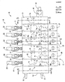
- Figure 1 is a top plan view of a segmented meltblowing die constructed according to the present invention showing polymer flow lines.
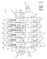
- Figure 2 is a top plan view of the present segmented die showing process air (primary air) flow lines.
- Figure 3 is a front elevation view of the segmented die illustrating the discharge of filaments onto a substrate.
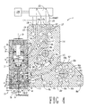
- Figure 4 is an enlarged sectional view taken along plane 4-4 of Figure 1 illustrating a middle section of the segmented manifold.
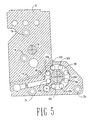
- Figure 5 is a sectional view taken along cutting plane 5-5 of Figure 1 illustrating an end plate of the segmented manifold.
- Figure 6 is a sectional view taken along cutting plane 6-6 of Figure 1 illustrating the end plate of the segmented manifold opposite that shown in Figure 5.
- Figure 7 is a sectional view of the segmented manifold taken along plane 7-7 of Figure 4 illustrating the polymer flow passages.
- Figure 8 is a sectional view of the segmented manifold taken along plane 8-8 of Figure 4 illustrating the process air flow passages.
-
- With reference to Figures 1, 2 and 3, the meltblowing die 10 of the present invention comprises a plurality of side-by-
side units 15 comprisingmanifold segments 11 andmodules 12. (In Figures 1, 2 and 3, the manifold segments are labeled 11A through 11F and the die modules are labeled 12A through 12F for the 6 segment structure. - In Figures 4 and 8, the manifold segments are labeled 11, it being understood that all the manifold segments are substantially identical.)
- In the embodiment illustrated in Figures 1, 2 and 3, each die unit 1 5 comprises a
manifold segment 11, adie module 12 mounted thereon, and avalve actuator 20 for controlling the flow of polymer melt through the die segment. As shown in Figure 3, each diemodule 12, has adie tip 13 which dischargesfilaments 14 onto a moving substrate (or collector) forming a layer or pattern of filaments on the substrate in a somewhat random fashion. - Each of the main components, manifold segment, die module, and controls is described in detail below.
- The
preferred die modules 12 are the type described in U.S. Patents 5,618,566 and 5,728,219, the disclosures of which are incorporated herein by reference. It should be understood, however, that other die modules may be used. See, for example, U.S. Patent Application Serial No. 09/021,426, filed February 10, 1998, entitled "MODULAR DIE WITH QUICK CHANGE DIE TIP OR NOZZLE." - As best seen in Figure 4, each die
module 12 consists of adie body 16 and adie tip 13. Thedie body 16 has formed therein an uppercircular recess 17 and a lowercircular recess 18 which are interconnected by a narrow opening 19. Theupper recess 17 defines acylindrical chamber 23 which is closed at its top by threadedplug 24. Avalve assembly 21 mounted withinchamber 23 comprises piston 22 having depending therefromstem 25. The piston 22 is reciprocally movable withinchamber 23, with adjustment pin 24a limiting the upward movement. Conventional o-rings may be used at the interface of the various surfaces for fluid seals as illustrated at 28. -
Side ports die body 16 to provide communication tochamber 23 above and below piston 22, respectively. As described in more detail below, theports - Mounted in the
lower recess 18 is a threaded valve insert member 30 having a central opening 31 extending axially therethrough and terminating in valve portion 32 at its lower extremity. The lower portion of insert member 30 is of reduced diameter and in combination with the die body inner wall defined in downwardly facingcavity 34. Upper portion 36 of insert member 30 abuts the top surface ofrecess 18 and has a plurality (e.g. 4) of circumferential port 37 formed therein and in fluid communication with the central passage 31. An annular recess extends around the upper portion 36 interconnecting the portions 37. -
Valve stem 25 extends through body opening 19 and axial opening 31 of insert member 30, and terminates atend 40 which is adapted to seat on valve port 32. The annular space 45 betweenstem 25 and opening 31 is sufficient for polymer melt to flow therethrough.End 40 ofstem 25 seats on port 32 with piston 22 and in its lower position withinchamber 23 as illustrated in Figure 4. As discussed below, actuation of the valve moves stemend 40 away from port 32 (open position), permitting the flow of polymer melt therethrough. Melt flows from the manifold 11 through side port 38, through 37, through annular space 45 discharging through port 32 into thedie tip assembly 13. Conventional o-rings may be used as the interface of the various surfaces as illustrated in the drawings. - The
die tip assembly 13 comprises a stack up of four parts: atransfer plate 41, adie tip 42, and two air plates 43a and 43b. Theassembly 13 can be preassembled and adjusted prior to mounting onto thedie body 16 usingbolts 50. -
Transfer plate 41 is a thin metal member having a central polymer opening 44 formed therein. Two rows ofair holes 49 flank the opening 44 as illustrated in Figure 4. When mounted on the lower mounting surface ofbody 16, thetransfer plate 41 covers thecavity 34 and therewith defines an air chamber with the air holes 49 providing outlets for air fromcavity 34. Opening 44 registers with port 32 with an o-ring between these providing a fluid seal at the interface surrounding port 32.Holes 49 register withair holes 57 formed indie tip 42. - The
die tip 42 comprises a base member which is co-extensive with thetransfer plate 41 and the mounting surface ofdie body 16, and a triangular nose piece 52 which may be integrally formed with the base. - The nose piece 52 terminates in
apex 56 which has a row oforifices 53 spaced therealong. - Air plates 43a and 43b are in flanking relationship to the nose piece 52 and define converging air slits which discharge at the apex of nose piece 52. Air (referred to as process air) is directed to opposite sides of the nose piece 52 into the converging slits and discharge therefrom as converging air sheets which meet at apex of nose piece 52 and contact the
filaments 14 emerging from the row oforifices 53. - The module 1 2 of the type disclosed in Figure 4 is described in more detail in the above referenced U.S. Patent 5,618,566. Also useable in the present invention are modules disclosed in U.S. Patent 5,728,219 and U.S. Patent Application Nos. 08/820,559 and 09/021,426. Other types of modules may also be used. The modules may dispense meltblown fibers, spirals, beads, sprays, or polymer coatings from the nozzle. Thus the module may be provided with a variety of nozzles including meltblowing nozzles, spiral spray nozzles, bead nozzles and coating nozzles.
- As seen in Figures 1-3,
segmented manifold 11 comprisesend plates middle section 11A-F. End plates Inlet 64 may haveremovable filter cartridge 68 for removing impurities from the melt stream. As described in detail belowair inlet 67 inplate 62 provides air, referred to as instrument air for operatingcontrol valves 20A-F indie modules 12A-F, respectively. - As seen in Figures 1, 2, 5 and 6,
end plate 62 has threaded bolt holes 71 a-d which align with countersunk bold holes 72a-d inmiddle plate 11A (only 72a and b shown in Figures 1 and 2, respectively).End plate 61 has countersunk holes 73a-d which align with thread holes 74a-d (only 74a, b shown) inmiddle plate 11F.Countersunk bolts 79 thus joinplate 62 to plate11A leaving surface 81 flush for adjoining middle plate 11B to 11A, andflush surface 82 for joiningend plate 61 tomiddle plate 11F. - Adjacent
middle sections 11A-F are joined bybolts 85 arranged in an alternating pattern of threaded and countersunk bolt holes. As seen in Figure 4, middle section 11D has four bored and countersunk bolt holes 86a-d and four threaded bolt holes 87a-d.Plates plate 11C, and threaded holes 87a-d will align with bored and countersunk holes inplate 11E (see Figures 1 and 2). This design of interchanging the pattern of countersunk holes and threaded holes in adjacent plates is repeated over the length of the die. Countersunk holes 86a-d are of sufficient depth so that the heads ofbolts 85 do not protrude beyond the outer lateral surface of the middle sections and thus permits the abutting surfaces of adjacent sections to be flush whenbolts 85 are tightened. Tightening ofbolts 85 establishes a metal-on-metal fluid seal between adjacent plates. O-rings may also be used to seal adjacent plates. - Referring to Figures 1, 4 and 7,
middle sections 11A-F have central polymer flow passage 91 (see Figure 4) which, when bolted together definecontinuous flow passage 92 which extends the length of the die.Polymer passage 92interconnects manifold segments 11A-F. A polymer melt enters the die throughinlet 64 and flows intopassage 92. Each middle plate has a hole 93a-f (see Figure 7) through which leads frompassage 92 into secondcontinuous passage 94 andholes 96A-F which is the outlet of the manifold and feeds polymer to diemodules 12A-F in parallel. The outlet ofpassages 96A-F register with the polymer inlet 38 (see Figure 4) of each die module. The lateral surfaces ofmiddle plates 11A-F andend plates bolts 85 as has been described. - Polymer melt thus enters the die through
plate 61 at 64, fillspassage 92, flows in parallel throughholes 93A-F, fillscontinuous passage 94, flows in parallel throughholes 96A-F, and enters diemodules 12A-F through passages 38 (see Figure 4). The polymer which enters the die modules is extruded to formfilaments 14 as has been described. The polymer manifold design wherein the polymer flows between the twocontinuous passages Heating element 97 maintains the polymer at the proper operating temperature. - Referring to Figures 2, 4, 5 and 6. Heated process air enters through
inlet 66 which registers with groove 101 (Figure 6) formed along the inner wall ofend plate 62.Middle sections 11A-F have a plurality of holes 102a-d which define continuous flow passages 103a-d which travel the length of the die as seen in Figure 2 (103c, d shown only). Air passages 103a-d interconnectmanifold segments 11A-F. The inlets of passages 103a-d register withgroove 101 so that air entering the groove will flow the length of the die fromplate 62 toplate 61. The outlets of passages 103a-d register withgroove 106 inplate 61 passages which turns the air and feeds thepassages 103e, f whereby flow back along the length of the die in the direction opposite that a passages 103a-d. The outlets topassages 103e, f register with groove 107 formed inplate 62 which receives the air and turns the air to travel back along the length of the die through passage 103g which discharges intogroove 108 ofend plate 61. Groove 108 feedspassage 103h and a portion of the air travels back along the die length throughpassage 103h while the rest of the air flows towards the manifold discharge throughslot 109 inplate 61. Air which returns to plate 62 via 103h flows towards the manifold discharge throughslot 111. Thus the air makes three or four passes along the length of the die before being discharge to the die modules.Central heating element 112 heats the multi-pass air to the operating temperature.Arrows 128 in Figures 2 indicate the direction of air flow. Because the process air temperature is hotter than the polymer operating temperature isolation holes 115 are provided inplates - As seen in Figures 2 and 8, process air flows towards the manifold discharge along both sides of the manifold through
slots Plates 11A-F have holes which defineair passage 113 which extends the length of the die.Slots passage 113 which feeds inparallel holes 114A-F which in turn feed associatedair input 39 in die modules 112A-F. The air flows through the die modules as has been described and is discharged as converging sheets of air ontofibers 14 extruded atdie tip apex 56. - Each die module comprises a
valve assembly 21 which is actuated by compressed air acting above or below piston 22. Instrument air is supplied to the top and bottom air chambers on each side of valve piston 22 (see Figure 4) byflow lines middle plate 11A-F. Three way solenoid valve 20D with electronic controller 120D controls the flow of instrument air.Instrument air inlet 118 is a continuous flow passage over the length of the die.Passage 119 in each plate delivers the air in parallel to each ofsolenoid valves 20A-F (shown schematically in Figure 4). The valve delivers the air to eitherpassage valve 21 is to be opened or closed. As illustrated in Figure 4, pressurized instrument air is delivered vialine 116 to the top of the piston 22 which acts to force the piston downward, while the controller 20D simultaneously opens the air chamber below the piston to exhaustport 121 vialines line 117 and would simultaneously open the upper side of the piston to exhaustport 123 vialine 124. The pressure beneath the piston forces the piston upward and unseatsvalve stem 25 to open the polymer flow passage to the die tip. Thus in the preferred mode each die module has a separate solenoid valve such that the polymer flow can be controlled through each die module independently. In this mode side holes 126 and 127 which intersectpassages - In a second preferred embodiment a single solenoid valve may be used to activate
valves 21 in a plurality of adjacent die modules. In this configuration the tops ofholes 116 and 117 (labeled 116a and 117a) are plugged andside holes flow lines hole 126 whilehole 127 would be opened to the exhaust. The instrument air flow is reversed to open the valve. - As indicated above, the
modular die assembly 10 of the present invention can be tailored to meet the needs of a particular operation. As exemplified in Figures 1, 2 and 3, six diesegments 11A-F, each about 0.75 inches in width are used in theassembly 10. Themanifold segments 11 are bolted together as described previously, and the heater elements installed. The length of the heater elements will be selected based on the number ofsegments 11 employed and will extend through most segments. Themodules 12 may be mounted on eachmanifold segment 11 before or after interconnecting thesegments 11, and may include any of thenozzles 13 previously described. Figure 3 illustrates fourmodules 12 with meltblowing die tips and two end modules with spiral nozzles. - At particularly advantageous feature of the present invention is that it permits (a) the construction of a meltblowing die with a wide range of possible lengths interchangeable manifold segments, and self contained modules, and (b) variation of die nozzles (e.g. meltblowing, spiral, or bead applicators) to achieve a predetermined and varied pattern. Variable die length and adhesive patterns may be important for applying adhesives to substrates of different sizes from one application to another. The following sizes and numbers are illustrative of the versatility of the module die construction of the present invention.
Die Assembly Broad Range Preferred Range Best Mode Number of Units (15) 2-1,000 2-100 5-50 Length of each Unit (15) (inches) 0.25-1.50" 0.5-1.00" 0.5-0.8" Orifice (53) Diameter (inches) 0.005-0.050" 0.01-0.040" 0.015-0.030" Orifices/Inch 5-50 10-40 10-30 Different Types of Nozzles (13) 2-4 2-3 2 - The lines, instruments, and controls are connected and operation commenced. A hot melt adhesive is delivered to the die 10 through
line 64, process air is delivered to the die throughline 66, and instrument air or gas is delivered throughlines 67. - Actuation of the control valves opens port 32 of each
module 12 as described previously, causing polymer melt to flow through eachmodule 12. In themeltblowing modules 15, the melt flows throughmanifold passages die tip assembly 13. The polymer melt is distributed laterally in thedie tip 13 and discharges throughorifices 53 as side-by-side filaments 14. Multi-pass process air meanwhile flows through manifold passages 103 where it is heated, intoslots modules 20A-F throughports 114A-F, respectifely. Air enters eachmodule 12 throughport 39 and flows throughholes filaments 14 discharging from theorifices 53 and by drag forces stretch them and deposit them onto the underlying substrate in a random pattern. This forms a generally uniform deposit of meltblown material on the substrate. - In each of the flanking
spiral nozzle modules 12, the polymer and air flows are basically the same, with the difference being on the nozzle tip. In the spiral nozzle, a monofilament is extruded and air jets are directed to impart a swirl on the monofilament. The swirling action draws down the monofilament and deposits it as overlapping swirls on the substrate as described in the above referenced U.S. Patent 5,728,219. - Typical operation parameters are as follows:
Polymer Hot melt adhesive Temperature of the Die and Polymer 280°F to 325°F Temperature of Air 280°F to 325°F Polymer Flow Rate 0.1 to 10 grms/hole/min. Hot air Flow Rate 0.1 to 2 SCFM/inch Deposition 0.05 to 500 g/m2 - As indicated above, the
die assembly 10 may be used in meltblowing any polymeric material, but meltblowing adhesives is the preferred polymer. The adhesives include EVA's (e.g. 20-40 wt% VA). These polymers generally have lower viscosities than those used in meltblown webs. Conventional hot melt adhesives useable include those disclosed in U.S. Patents 4,497,941, 4,325,853, and 4,315,842, the disclosure of which are incorporated herein by reference. The preferred hot melt adhesives include SIS and SBS block copolymer based adhesives. These adhesives contain block copolymer, tackifier, and oil in various ratios. The above melt adhesives are by way of illustration only; other melt adhesives may also be used. - Although the present invention has been described with reference to meltblowing hot melt adhesive, it is to be understood that the invention may also be used to meltblow polymer in the manufacture of webs. The dimensions of the die tip may have a small difference in certain features as described in the above referenced U.S. Patents 5,145,689 and 5,618,566.
- The typical meltblowing web forming resins include a wide range of polyolefins such as propylene and ethylene homopolymers and copolymers. Specific thermoplastics include ethylene acrylic copolymers, nylon, polyamides, polyesters, polystryrene, poly(methyl methacrylate), polytrifluoro-chloroethylene, polyurethanes, polycarboneates, silicone sulfide, and poly(ethylene terephthalate), pitch, and blends of the above. The preferred resin is polypropylene. The above list is not intended to be limiting, as new and improved meltblowing thermoplastic resins continue to be developed.
- The invention may also be used with advantage in coating substrates or objects with thermoplastics.
- The thermoplastic polymer, hot melt adhesives or those used in meltblowing webs, may be delivered to the die by a variety of well known means including extruders metering pumps and the like.
Claims (10)
- An assemblage of at least two modular fluid dispensing units, each modular fluid dispensing unit comprising a manifold block having a fluid passage for conveying therethrough a material to be dispensed, said manifold block comprising a front wall and a pair of oppositely disposed side walls, a dispensing valve mounted upon said front wall of said manifold block for receiving and dispensing the material conveyed through said fluid passage of said manifold block, a die tip or nozzle connected to the dispensive valve and having a flow passage in fluid communication with the fluid passage of the manifold block for receiving the material and discharging the material therefrom and a fastener connecting one of said oppositely disposed side walls of said manifold block of said first modular fluid dispensing unit to one of said oppositely disposed side walls of said manifold block of said second modular fluid dispensing unit such that said at least two modular fluid dispensing units can be fixedly connected together thereby forming the assemblage of modular fluid dispensing units collectively carrying a multiple number of dispensing valves and a multiple number of die tips or nozzles.
- The assemblage of claim 1, therein said fastener is a threaded fastener and said manifold block includes a threaded bore for receiving said threaded fastener.
- The assemblage of either claim 1 or claim 2, wherein said dispensing valve is a hot melt adhesive dispensing valve.
- The assemblage of any preceding claim, wherein said manifold block includes a heater configured to heat the material to be dispensed.
- The assemblage of any preceding claim, wherein said dispensing valve is pneumatically operated and said manifold block further comprises air passageways for directing operating air to said dispensing valve mounted upon said front wall.
- The assemblage of claim 5, further comprising a solenoid valve coupled with said manifold block for controlling the operating air.
- A die unit comprising a manifold block having a front wall, a pair of oppositely disposed side walls and first and second sections, a fluid passageway in said first section for conveying therethrough a material to be dispensed, and an air passageway in said second section for conveying therethrough process air to be discharged adjacent the material being dispensed, first and second heaters respectively contained in said first and second sections and configured to separately heat the material in said fluid passageway and the process air in said air passageway to different temperatures, a thermal isolator positioned between said first and second sections to disrupt the flow of heat between said fluid passageway and said air passageway, a dispensing valve coupled with said front wall of said manifold block for receiving and dispensing the material conveyed through said fluid passageway of said first section and for receiving and discharging the process air conveyed through said air passageway of said second section, and a die tip or nozzle connected to the dispensive valve and having a flow passage in fluid communication with the fluid passage of the manifold block for receiving the material and discharging the material therefrom.
- The die unit of claim 7, wherein said thermal isolator comprises a hole in said manifold, said hole located between said first and second sections.
- The die unit of claim 7, wherein said thermal isolator comprises a plurality of holes in said manifold block, said holes located between said first and second sections.
- A segmented die assembly comprising first and second side by side die units as claimed in any one of claims 7 to 9 and a fastener connecting one of said oppositely disposed side walls of said manifold block of said first die unit to one of said oppositely disposed side walls of said manifold block of said second die unit.
Applications Claiming Priority (5)
| Application Number | Priority Date | Filing Date | Title |
|---|---|---|---|
| US77780 | 1979-09-21 | ||
| US138039 | 1987-12-28 | ||
| US7778098P | 1998-03-13 | 1998-03-13 | |
| US09/138,039 US6220843B1 (en) | 1998-03-13 | 1998-08-20 | Segmented die for applying hot melt adhesives or other polymer melts |
| EP99911359A EP1062051B1 (en) | 1998-03-13 | 1999-03-12 | Segmented die for applying hot melt adhesives or other polymer melts |
Related Parent Applications (1)
| Application Number | Title | Priority Date | Filing Date |
|---|---|---|---|
| EP99911359A Division EP1062051B1 (en) | 1998-03-13 | 1999-03-12 | Segmented die for applying hot melt adhesives or other polymer melts |
Publications (2)
| Publication Number | Publication Date |
|---|---|
| EP1407830A2 true EP1407830A2 (en) | 2004-04-14 |
| EP1407830A3 EP1407830A3 (en) | 2004-11-03 |
Family
ID=32033899
Family Applications (1)
| Application Number | Title | Priority Date | Filing Date |
|---|---|---|---|
| EP03079172A Withdrawn EP1407830A3 (en) | 1998-03-13 | 1999-03-12 | Segmented die for applying hot melt adhesives or other polymer melts |
Country Status (1)
| Country | Link |
|---|---|
| EP (1) | EP1407830A3 (en) |
Cited By (2)
| Publication number | Priority date | Publication date | Assignee | Title |
|---|---|---|---|---|
| CN108745785A (en) * | 2018-07-25 | 2018-11-06 | 江苏控真空注胶技术有限公司 | A kind of modular injecting glue head valve island |
| WO2019089378A1 (en) * | 2017-10-31 | 2019-05-09 | Nordson Corporation | Liquid material dispensing system having a sleeve heater |
Citations (10)
| Publication number | Priority date | Publication date | Assignee | Title |
|---|---|---|---|---|
| US4325853A (en) | 1980-07-31 | 1982-04-20 | Gulf Oil Corporation | Hot melt adhesive compositions containing rosin esters |
| US4497941A (en) | 1981-10-16 | 1985-02-05 | Exxon Research & Engineering Co. | Ethylene copolymers for hot melt systems |
| US4687137A (en) | 1986-03-20 | 1987-08-18 | Nordson Corporation | Continuous/intermittent adhesive dispensing apparatus |
| US4891249A (en) | 1987-05-26 | 1990-01-02 | Acumeter Laboratories, Inc. | Method of and apparatus for somewhat-to-highly viscous fluid spraying for fiber or filament generation, controlled droplet generation, and combinations of fiber and droplet generation, intermittent and continuous, and for air-controlling spray deposition |
| US4949668A (en) | 1988-06-16 | 1990-08-21 | Kimberly-Clark Corporation | Apparatus for sprayed adhesive diaper construction |
| US4983109A (en) | 1988-01-14 | 1991-01-08 | Nordson Corporation | Spray head attachment for metering gear head |
| US5102484A (en) | 1990-06-26 | 1992-04-07 | J&M Consultants Inc. | Method and apparatus for generating and depositing adhesives and other thermoplastics in swirls |
| US5145689A (en) | 1990-10-17 | 1992-09-08 | Exxon Chemical Patents Inc. | Meltblowing die |
| US5618566A (en) | 1995-04-26 | 1997-04-08 | Exxon Chemical Patents, Inc. | Modular meltblowing die |
| US5728219A (en) | 1995-09-22 | 1998-03-17 | J&M Laboratories, Inc. | Modular die for applying adhesives |
Family Cites Families (4)
| Publication number | Priority date | Publication date | Assignee | Title |
|---|---|---|---|---|
| US3985481A (en) * | 1974-12-09 | 1976-10-12 | Rothmans Of Pall Mall Canada Limited | Extrusion head for producing polymeric material fibres |
| US4051861A (en) * | 1975-11-03 | 1977-10-04 | Skinner Precision Industries, Inc. | Arrangement for connecting manifold blocks |
| US4079864A (en) * | 1976-12-15 | 1978-03-21 | Cox James R | Manifold for liquid dispensing apparatus |
| US5605720A (en) * | 1996-04-04 | 1997-02-25 | J & M Laboratories Inc. | Method of continuously formulating and applying a hot melt adhesive |
-
1999
- 1999-03-12 EP EP03079172A patent/EP1407830A3/en not_active Withdrawn
Patent Citations (11)
| Publication number | Priority date | Publication date | Assignee | Title |
|---|---|---|---|---|
| US4325853A (en) | 1980-07-31 | 1982-04-20 | Gulf Oil Corporation | Hot melt adhesive compositions containing rosin esters |
| US4497941A (en) | 1981-10-16 | 1985-02-05 | Exxon Research & Engineering Co. | Ethylene copolymers for hot melt systems |
| US4687137A (en) | 1986-03-20 | 1987-08-18 | Nordson Corporation | Continuous/intermittent adhesive dispensing apparatus |
| US4687137B1 (en) | 1986-03-20 | 1988-10-25 | ||
| US4891249A (en) | 1987-05-26 | 1990-01-02 | Acumeter Laboratories, Inc. | Method of and apparatus for somewhat-to-highly viscous fluid spraying for fiber or filament generation, controlled droplet generation, and combinations of fiber and droplet generation, intermittent and continuous, and for air-controlling spray deposition |
| US4983109A (en) | 1988-01-14 | 1991-01-08 | Nordson Corporation | Spray head attachment for metering gear head |
| US4949668A (en) | 1988-06-16 | 1990-08-21 | Kimberly-Clark Corporation | Apparatus for sprayed adhesive diaper construction |
| US5102484A (en) | 1990-06-26 | 1992-04-07 | J&M Consultants Inc. | Method and apparatus for generating and depositing adhesives and other thermoplastics in swirls |
| US5145689A (en) | 1990-10-17 | 1992-09-08 | Exxon Chemical Patents Inc. | Meltblowing die |
| US5618566A (en) | 1995-04-26 | 1997-04-08 | Exxon Chemical Patents, Inc. | Modular meltblowing die |
| US5728219A (en) | 1995-09-22 | 1998-03-17 | J&M Laboratories, Inc. | Modular die for applying adhesives |
Cited By (4)
| Publication number | Priority date | Publication date | Assignee | Title |
|---|---|---|---|---|
| WO2019089378A1 (en) * | 2017-10-31 | 2019-05-09 | Nordson Corporation | Liquid material dispensing system having a sleeve heater |
| US11110483B2 (en) | 2017-10-31 | 2021-09-07 | Nordson Corporation | Liquid material dispensing system having a sleeve heater |
| CN108745785A (en) * | 2018-07-25 | 2018-11-06 | 江苏控真空注胶技术有限公司 | A kind of modular injecting glue head valve island |
| CN108745785B (en) * | 2018-07-25 | 2023-08-15 | 江苏一控真空注胶技术有限公司 | Modular injecting glue head valve island |
Also Published As
| Publication number | Publication date |
|---|---|
| EP1407830A3 (en) | 2004-11-03 |
Similar Documents
| Publication | Publication Date | Title |
|---|---|---|
| EP1062051B1 (en) | Segmented die for applying hot melt adhesives or other polymer melts | |
| EP1071519B1 (en) | Segmented metering die for hot melt adhesives or other polymer melts | |
| US5728219A (en) | Modular die for applying adhesives | |
| US6422848B1 (en) | Modular meltblowing die | |
| US6074597A (en) | Meltblowing method and apparatus | |
| EP0553237B1 (en) | Melt-blowing die | |
| AU704281B2 (en) | Improved meltblowing method and system | |
| US5618566A (en) | Modular meltblowing die | |
| US6210141B1 (en) | Modular die with quick change die tip or nozzle | |
| EP1083999A1 (en) | Method and apparatus for applying a controlled pattern of fibrous material to a moving substrate | |
| EP1201320B1 (en) | Dispensing system using a die tip having an air foil | |
| US6680021B1 (en) | Meltblowing method and system | |
| EP0866152B1 (en) | Meltblowing apparatus and process | |
| US20050092775A1 (en) | Liquid material dispensing apparatus and method utilizing pulsed pressurized air | |
| EP1407830A2 (en) | Segmented die for applying hot melt adhesives or other polymer melts | |
| EP0987352A2 (en) | Modular meltblowing die |
Legal Events
| Date | Code | Title | Description |
|---|---|---|---|
| PUAI | Public reference made under article 153(3) epc to a published international application that has entered the european phase |
Free format text: ORIGINAL CODE: 0009012 |
|
| 17P | Request for examination filed |
Effective date: 20031223 |
|
| AC | Divisional application: reference to earlier application |
Ref document number: 1062051 Country of ref document: EP Kind code of ref document: P |
|
| AK | Designated contracting states |
Kind code of ref document: A2 Designated state(s): DE FR GB IT |
|
| RIN1 | Information on inventor provided before grant (corrected) |
Inventor name: ALLEN, MARTIN A. |
|
| PUAL | Search report despatched |
Free format text: ORIGINAL CODE: 0009013 |
|
| AK | Designated contracting states |
Kind code of ref document: A3 Designated state(s): DE FR GB IT |
|
| RIC1 | Information provided on ipc code assigned before grant |
Ipc: 7B 05B 7/08 B Ipc: 7D 01D 5/098 B Ipc: 7D 01D 4/02 B Ipc: 7B 05C 5/02 A |
|
| AKX | Designation fees paid |
Designated state(s): DE FR GB IT |
|
| STAA | Information on the status of an ep patent application or granted ep patent |
Free format text: STATUS: THE APPLICATION IS DEEMED TO BE WITHDRAWN |
|
| 18D | Application deemed to be withdrawn |
Effective date: 20060131 |