1. FIELD OF THE INVENTION
-
The present invention relates to an information display device, and
more particularly, it belongs to a technical field of an information display
device suitable for displaying an operation menu at the time of blind
operation of on-vehicle apparatuses by a multifunction switch, the
on-vehicle apparatuses being a navigation system, an audio apparatus, and
so on mounted on a vehicle.
2. DESCRIPTION OF THE RELATED ART
-
Conventionally, a multifunction switch has been well known that is
intended for use in operating a navigation system, an audio apparatus, an
airconditioner, and so on by blind operation from a driver's seat or a front
passenger's seat of a vehicle while the vehicle is being driven (for example,
refer to Japanese Patent Laid-open No. 2000-276976).
-
This multifunction switch is so structured that operation switches
are disposed at positions where respective fingers are situated when an
operator holds the multifunction switch, thereby enhancing operability, and
it is provided with a jog encoder switch with a push function, thereby
realizing diversified switch operations. This multifunction switch enables
an operator to operate the apparatuses by blind operation while seeing a
hierarchical operation menu displayed on a display screen mounted on a
vehicle.
-
In a conventional information display device using the
above-described multifunction switch, the following two methods have
been typically implemented as methods for displaying an operation menu
on a display screen.
- (1) Menu display is kept on stand-by at a normal time and the menu
is displayed by switch operation. When no switch operation is executed
for a predetermined period of time, the menu is erased from a display
screen.
- (2) A part of the screen is reserved as a menu display area for
constantly keeping the menu displayed thereon.
-
-
However, the former method of the above prior arts requires,
before the operation of the apparatus, switch operation for the display of an
initial menu, which poses a problem of low operability.
-
In the latter method, the screen appears cluttered due to a large
information amount displayed on the screen. Moreover, an area for
displaying other apparatus information becomes small. This is
disadvantageous especially for a navigation function since a map display
area is forced to be small.
SUMMARY OF THE INVENTION
-
The present invention is made in view of the problems stated above,
and an object thereof is to provide an information display device excellent
in operability in which quick menu display is possible when an operator
operates a switch for an apparatus and a menu non-display window
appears again after the switch operation is completed, thereby preventing
the obstruction to a display area of apparatus information.
-
In order to achieve the objects stated above, an information display
device according to the present invention includes: a display having a
display screen on which information on an apparatus is displayed; an input
means including an operation switch through which operation control of
the apparatus is performed and outputting a switch signal when the
operation switch is operated; a proximity detector that detects that an
operator's hand comes in a range which is a predetermined distance away
from the input means; and a menu display controller that causes a
hierarchical menu showing an operation item group of the apparatus to be
displayed on the display screen in response to the switch signal from the
input means when the operator's hand comes in the range, and terminates
menu display when the operator's hand is taken off the input means.
-
In the information display device, a menu is displayed on the
display screen when an operator's hand comes in the range, in other words,
immediately before the operator touches the input means. Then, menu
display is terminated when the operator's hand is taken off the input means.
-
Therefore, compared with the prior art requiring switch operation
for menu display, the operation procedure steps can be lessened, so that the
operation burden on an operator can be lightened. In addition, since a
menu is displayed only when the apparatus is to be operated, an area for
constant display of the menu is not required, so that a display area of other
apparatus information can be enlarged, compared with the prior art in
which a part of a screen is set as a menu display area.
-
Further, in the information display device, the menu display is
continued while the operator's hand is in the range.
-
Here, the control performed in the device of the prior art is such
that, when a predetermined period of time has passed after switch
operation, menu display is terminated and a display screen is changed to a
menu non-display window, but in this case, when an operator interrupts the
switch operation for a predetermined period of time or longer, the operator
is forced to take trouble of searching again for a desired menu from an
initially displayed menu on the top hierarchical level (initial menu).
-
In the information display device, the state in which the operator's
hand is in the range is judged to indicate that the operator has an intention
to continue the switch operation, and accordingly, the menu display is
continued, which can save the operator the aforesaid trouble.
-
The information display device may further include: a counter that
counts a period of time during which the operator's hand is in the range;
and a delay time setting means for setting, based on the counted period of
time, a delay time that is a period of time from an instant at which the
operator's hand is taken off the input means until the menu display is
terminated, and, when the operator's hand is taken off the input means, the
menu display controller terminates the menu display after the set delay
time has passed.
-
In the information display device, the period of time during which
the operator's hand is in the range is counted in advance, and when the
operator's hand is taken off the input means, the menu display is continued
for the delay time that is set based on the counted period of time.
Therefore, it is possible to reduce the trouble of repeating a previous
operation when the operator returns to the switch operation after
momentarily concentrating on driving due to some unexpected disturbance
which occurs during the switch operation.
-
Here, menus on upper hierarchical levels close to the initial menu
are accessible from the initial menu with a small number of switch
operations, but menus on lower hierarchical levels require a larger number
of switch operations, which lengthens the accessible time from the initial
menu. Therefore, based on such recognition as "the period of time during
which the operator's hand is in the range is longer = a menu on a lower
hierarchical level is displayed", the delay time is set longer for a menu on a
lower hierarchical level. In this manner, the operation burden of
executing the display of a menu on a lower hierarchical level can be
lightened.
-
The delay time setting means may set the delay time longer as a
level of a displayed menu is lower in hierarchy, when a plurality of menus
are provided in a hierarchical manner on lower levels of an initial menu
that is a menu displayed when the operator's hand comes in the range.
-
In the information display device, as a level of a finally displayed
menu is lower in hierarchy, the delay time is set longer, which can lighten
the burden on the operator, similarly to the above effect.
-
The information display device may further include an operation
history memory that stores an operation history based on the inputted
switch signal, and the delay time setting means sets the delay time based
on the operation history.
-
In the information display device, the delay time is set based on the
operation history, which makes it possible to set the delay time according
to each operator.
-
For example, in the case of an operator who often makes a display
selection of a menu on an upper hierarchical level relatively close to the
initial menu, it is inferred that this operator often interrupts the operation
while this menu is being displayed. Therefore, the delay time of a menu
that is frequently used is set longer even if it is a menu on an upper
hierarchical level, so that the trouble of redisplaying a desired menu can be
reduced.
-
The information display device may further include an operation
completion detector that detects operation completion of the apparatus, and
the delay time setting means sets the delay time shorter when the operation
of the apparatus is completed than when the operation of the apparatus is
not completed.
-
In the information display device, the delay time is set shorter when
the operation of an apparatus is completed than when the operation of an
apparatus is not completed, so that it can be prevented that a menu is
displayed on the display screen for a long time even though the operation
is completed, thus obstructing the display of necessary apparatus
information.
BRIEF DESCRIPTION OF THE DRAWINGS
-
- FIG 1 is a block diagram showing the configuration of an
information display device of this embodiment;
- FIG. 2(a) and FIG 2(b) are views each showing a display screen of
a display;
- FIG 3 is a view showing a hierarchical structure of a menu;
- FIG. 4 is a perspective view of the structure of a multifunction
switch 2; and
- FIG. 5 is a flowchart showing the flow of a time-out time setting
control process performed by a menu display controller.
-
DETAILED DESCRIPTION OF THE PREFERRED
EMBODIMENTS
-
Hereinafter, an embodiment of the present invention will be
explained based on the drawings.
-
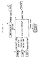
FIG. 1 is a block diagram showing the configuration of an
information display device of this embodiment.
-
The display device comprises a display 1, a multifunction switch
(corresponding to an input means) 2, a menu display controller 3, a counter
4, a timer 5, a memory (corresponding to an operation history memory) 6,
and on-vehicle apparatuses 7 such as a navigation system, an audio
apparatus, and an airconditioner.
-
The display 1 has a display screen on which information on the
on-vehicle apparatuses 7 such as the navigation system, the audio
apparatus, and the airconditioner is displayed. Further, the display screen
displays a hierarchical menu showing an operation control command group
of each of the on-vehicle apparatuses 7 when a driver or a passenger in a
front passenger's seat (hereinafter, referred to as an operator) is to operate
any one of the on-vehicle apparatuses 7.
-
FIG. 2(a) and FIG. 2(b) are views each showing a display screen 1a
of the display 1. FIG. 2(a) shows a menu non-display window, on which,
for example, navigation information or the like is being displayed. FIG.
2(b) shows a state when a main menu (initial menu) A that is a menu on a
top hierarchical level is displayed on a part of the display screen 1a.
Four items, namely, audio, airconditioner, navigation, and command are
displayed in this main menu A.
-
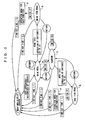
Note that, as shown in FIG 3, a main item menu B and a submenu
C are provided as menus on lower hierarchical levels of the main menu A.
Functions of an item selected in the main menu A are displayed in the main
item menu B. In the submenu C, items such as visual, vehicle
information, option, and setting are displayed.
-
Further, on a lower hierarchical level of the main item menu B, an
operation menu D for each function selected in the main item menu B is
provided. Moreover, on a lower hierarchical level of the submenu C,
provided is a sub item menu E in which each function of the item selected
in the submenu C is displayed, and an operation menu F for each function
selected in the sub item menu E is provided on a lower hierarchical level of
the sub item menu E. When one of the operation items displayed in the
operation menu D or F is selected, the selected item is executed.
-
The aforesaid multifunction switch 2 is a switch through which a
selection from a menu displayed on the display screen of the display 1 is
made to operate any one of the on-vehicle apparatuses 7, and it has an IR
sensor (corresponding to a proximity detector) 8 that detects whether or
not an operator's hand is in a range 28 which is a predetermined distance
away from the multifunction switch 2. The structure of this multifunction
switch 2 will be described later.
-
The aforesaid menu display controller 3 is intended for controlling
screen display of the display 1 according to a switch input from the
multifunction switch 2. Further, according to an operation control
command of the on-vehicle apparatus 7 selected by the operator from the
menu, the menu display controller 3 outputs a control signal to a control
section of the on-vehicle apparatus 7. The menu display controller 3
functions as a delay time setting means.
-
The aforesaid counter 4 measures the period of time (count value)
between the detection of the operator's hand by the IR sensor 8 and an
instant at which the operator's hand becomes undetected and outputs the
count value to the menu display controller 3.
-
The aforesaid timer 5 counts down a time-out time that is set by the
menu display controller 3 based on the count value and outputs a time-out
signal to the menu display controller 3.
-
The aforesaid memory 6, which is a nonvolatile memory device
such as EEPROM, stores an operation history of the operator based on a
switch signal outputted from the multifunction switch 2 to the menu
display controller 3.
-
Next, an example of the structure of the multifunction switch 2 will
be explained.
-
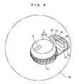
FIG 4 is a perspective view showing the structure of the
multifunction switch 2.
-
The shape of this multifunction switch 2 is such that it is
constituted of a grip portion 2a for having an operator's palm placed
thereon and a switch portion 2b, which is provided in a front direction of
this grip portion 2a, for having operator's four fingers placed thereon.
-
The aforesaid IR sensor 8 is provided on an upper face of the grip
portion 2a. Further, a jog encoder switch 21 that is operated with the
thumb is provided on a periphery portion of the grip portion 2a.
-
On an upper face of the switch portion 2b, provided are four select
switches 22 to 25 arranged in a square with a cross-shaped interval therein,
a submenu changeover switch 26 positioned on a vehicle front side of
these select switches 22 to 25, and a return switch 27 positioned on a
vehicle rear side of the select switches 22 to 25. All of them are
push-type switches.
-
The aforesaid select switches 22 to 25 are switches for use in
selecting a desired item from the items (audio, airconditioner, navigation,
command) displayed in the main menu A or from the items (selection of
visual, vehicle information, option, and setting) displayed in the submenu
C, and when a switch corresponding to a desired item out of the displayed
items is pushed, the main item menu B or the sub item menu E
corresponding to the selected item is displayed.
-
The aforesaid submenu changeover switch 26 is a switch for use in
changing the main menu A to the submenu C. The return switch 2 is a
switch for use in displaying a menu one-level higher in hierarchy than the
menu displayed on the display screen 1a.
-
In FIG. 3 described above, in the state in which the main menu A is
displayed on the display screen 1a of the display 1, the operation of any
one of the select switches 22 to 25 causes the main item menu B to be
displayed, while the operation of the submenu changeover switch 26
causes the submenu C to be displayed. Further, the operation of any one
of the switches 22 to 25 while the submenu C is displayed causes the sub
item menu E to be displayed.
-
The jog encoder switch 21 is used in order to display the operation
menu D or E for each function from the main item menu B or the sub item
menu E.
-
Next, the operation will be explained.
- Time-out Time Setting Control Process -
-
FIG. 5 is a flowchart showing the flow of a time-out time setting
control process by the menu display controller 3.
-
In Step S1, it is detected based on a sensor signal from the IR
sensor 8 whether or not the operator's hand is in the range 28 around the
multifunction switch 2. When the operator's hand is in the range 28
around the multifunction switch 2, the control proceeds to Step S2. When,
on the other hand, the operator's hand is not in the range 28 around the
multifunction switch 2, Step S 1 is repeated.
-
In Step S2, a command for the display of the main menu A on the
display screen 1a is outputted to the display 1.
-
In Step S3, a count-ON signal is outputted to the counter 4 so that
the counter 4 starts counting.
-
In Step S4, it is detected based on a sensor signal from the IR
sensor 8 whether or not the operator's hand is taken off the multifunction
switch 2. When the operator's hand is taken off the multifunction switch
2, the control proceeds to Step S5. When, on the other hand, the
operator's hand is in the range 28 around the multifunction switch 2, Step
S4 is repeated.
-
In Step S5, a count-OFF signal is outputted to the counter 4 so that
the counter 4 stops counting, and the count value is received.
-
In Step S6, a time-out time (corresponding to a delay time) T0 is set
based on the count value, and the timer 5 is started.
-
In Step S7, it is detected whether or not the current state is an
operation completion state, in other words, whether or not one of the
operation items displayed in the operation menu D or F has been already
selected. When the operation item has been already selected, the control
proceeds to Step S15, and when the operation item has not been selected
yet, the control proceeds to Step S8. The operation completion of the
apparatus is detected by an operation completion detector. The menu
display controller 3 functions as the operation completion detector.
-
In Step S8, it is judged whether or not the main menu A is
displayed on the display screen 1a. When the main menu A is displayed,
the control proceeds to Step S9, and otherwise, the control proceeds to
Step S10.
-
In Step S9, a time-out time (corresponding to a delay time) T1 (T1 >
T0) is set based on the count value. This time-out time is set longer as the
count value is larger. Note that the set time-out time (corresponding to a
delay time) T1 is adjusted according to an operation history stored in the
memory 6. For example, when a menu frequently used is displayed, the
time-out time is set longer, and when a menu seldom used is displayed, the
time-out time is set shorter.
-
In Step S10, it is judged whether or not the main item menu B or
the submenu C is displayed on the display screen 1a. When the main
item menu B or the submenu C is displayed, the control proceeds to Step
S11, and otherwise, the control proceeds to Step S12.
-
In Step S11, a time-out time (corresponding to a delay time) T2 (T2
> T1) is set based on the count value. Adjustment of the set time-out time
(corresponding to a delay time) T2 may be further made according to the
operation history.
-
In Step S12, it is judged whether or not the operation menu D or the
sub item menu E is displayed on the display screen 1a. When the
operation menu D or the sub item menu E is displayed, the control
proceeds to Step S13, and when the operation menu F is displayed, the
control proceeds to Step S 14.
-
In Step S 13, a time-out time (corresponding to a delay time) T3 (T3
> T2) is set based on the count value. Adjustment of the set time-out time
(corresponding to a delay time) T3 may be further made according to the
operation history.
-
In Step S 14, a time-out time (corresponding to a delay time) T4 (T4
> T3) is set based on the count value. Adjustment of the set time-out time
T4 (corresponding to a delay time) may be further made according to the
operation history.
-
In Step S 15, it is judged whether or not the timer 5 has reached the
time-out time based on whether or not the timer 5 has outputted a time-out
signal. When the timer 5 has reached the time-out time, the control
proceeds to Step S16, and when the timer 5 has not reached the time-out
time, the control proceeds to Step S 17.
-
In Step S 16, the timer 5 is stopped.
-
In Step S 17, it is detected based on a sensor signal from the IR
sensor 8 whether or not the operator's hand is in the range 28 around the
multifunction switch 2. When the operator's hand is in the range 28
around the multifunction switch 2, the control proceeds to Step S18.
When, on the other hand, the operator's hand is not in the range 28 around
the multifunction switch 2, the control returns to Step S 15.
-
In Step S 18, the timer 5 is stopped and initialized.
-
In Step S 19, the menu display is terminated, and a command for the
display of the menu non-display window on the display screen 1a is
outputted to the display 1.
-
In Step S20, the counter 4 and the timer 5 are initialized, thereby
finishing this control.
-
Next, the effects will be explained.
-
In the information display device of this embodiment, the effects
listed as follows are obtainable.
- (1) Based on the sensor signal of the IR sensor 8, the main menu A
is displayed on the display screen 1a when the operator's hand comes in the
range 28 around the multifunction switch 2, and when the operator's hand
is taken off the multifunction switch 2, a menu is erased and the menu
non-display window is displayed. This makes it possible to reduce the
operation procedure steps to lighten the operation burden on the operator,
compared with a prior art requiring switch operation for menu display. In
addition, since a menu is displayed only when an apparatus is to be
operated, an area for constant display of the menu is not required, so that a
display area of other apparatus information can be enlarged, compared
with the prior art in which a menu display area is set in a part of a screen.
- (2) The menu non-display window is displayed after the time-out
time has passed after the operator's hand is taken off the multifunction
switch 2. This makes it possible to save the operator the trouble of
repeating a previous operation when the operator returns to switch
operation after momentarily concentrating on driving due to some
unexpected disturbance during the switch operation.
- (3) As a menu that is displayed on the display screen 1a when the
operator's hand is taken off the multifunction switch 2 is farther from the
main menu A in terms of the level in the hierarchy, the time-out time is set
longer. This makes it possible to lighten the operation burden in the
re-display of the operation menu D or F, or the sub item menu E, which
requires a lot of trouble for display, from the main menu A.
- (4) The operation history is stored in the memory 6, and as a
displayed menu is a more frequently used one, the time-out time is set
longer. This makes it possible to reduce the trouble of redisplaying a
frequently used menu.
- (5) The time-out time To in the operation completion state is set
shorter than the time-out times T1 to T4 not in the operation completion
state. This makes it possible to prevent the display of the menu for a long
time in spite of that the operation has been completed.
-
-
Hitherto, the embodiment of the present invention is explained, but
the specific configuration of the present invention is not limited to this
embodiment, and changes in design and so on not departing from the spirit
of the present invention are to be embraced in the present invention.
-
For instance, an example when the IR sensor is used as the
proximity detector is shown in this embodiment, but any sensor may be
used as long as it is a proximity sensor or a touch sensor capable of
detecting a human body. Moreover, the proximity detector may be a
separate structure from the input means.
-
Further, the constitution of menus, the number of menu hierarchical
levels, the structure of the multifunction switch (input means), and so on
are not limited to those in this embodiment. For example, seesaw
switches and other switches may be used as the select switches 22 to 25,
the submenu changeover switch 26, and the return switch 27.