EP1406152B1 - Inner-force providing input device having a power-operated actuator for generating a click feel - Google Patents
Inner-force providing input device having a power-operated actuator for generating a click feel Download PDFInfo
- Publication number
- EP1406152B1 EP1406152B1 EP20030021497 EP03021497A EP1406152B1 EP 1406152 B1 EP1406152 B1 EP 1406152B1 EP 20030021497 EP20030021497 EP 20030021497 EP 03021497 A EP03021497 A EP 03021497A EP 1406152 B1 EP1406152 B1 EP 1406152B1
- Authority
- EP
- European Patent Office
- Prior art keywords
- operating member
- torque
- operating
- angle
- rotary knob
- Prior art date
- Legal status (The legal status is an assumption and is not a legal conclusion. Google has not performed a legal analysis and makes no representation as to the accuracy of the status listed.)
- Expired - Fee Related
Links
Images

Classifications
-
- G—PHYSICS
- G06—COMPUTING; CALCULATING OR COUNTING
- G06F—ELECTRIC DIGITAL DATA PROCESSING
- G06F3/00—Input arrangements for transferring data to be processed into a form capable of being handled by the computer; Output arrangements for transferring data from processing unit to output unit, e.g. interface arrangements
- G06F3/01—Input arrangements or combined input and output arrangements for interaction between user and computer
- G06F3/016—Input arrangements with force or tactile feedback as computer generated output to the user
Definitions
- a feel similar to that of a click mechanism is generated at around the time the operating member reaching the second position.
- an impact similar to that of a click mechanism is generated. Accordingly, even in case the operating member is to be operated straight-line, a click feel can be generated that is similar to that to be obtained by a click mechanism.
- the CPU 4 has a torque arithmetic operating section 4d for arithmetically operating a torque to be delivered to the rotary knob 1 on the basis of a rotation angle detected by the rotation-angle detecting means 3 and outputting a control signal to control the motor 2 depending upon the torque.
- the CPU 4 has the proportional multiplier and the upper limit value of torque in providing a torque product to the rotary knob 1, which are configured adjustable by not-shown input means.
- k ⁇ 2 (Tmax • t) + (T2 • t) and T2 ⁇ Tmax result as shown for example in Fig. 5 .
- a torque having a value Tmax is provided to the rotary knob 1 for a time t.
- a torque having a value T2 is provided to the rotary knob 1 for a time t.
- the present embodiment thus configured operates as in the following.
Description
- The present invention relates to an inner-force providing input device according to the preamble of
claim 1 or claim 4. - Conventionally, there are mechanical input devices adapted to generate a click feel on the operating member by the click mechanism. However, there is no inner-force providing input device having a power-operated actuator to deliver a torque to the operating member under electric control thereby generating a click feel thereon. Realizing such an inner-force providing input device has been desired.
- In this situation, the present inventor have started to develop the present invention in an attempt to meet the foregoing demand, and made the following test product in the development stage of the invention.
- The inner-force providing input device trial-made in the development stage of the invention has an operating member to be manually rotated, e.g. rotary knob, a power-operated actuator for delivering a torque to the operating member, e.g. motor, rotation-angle detecting means such as an encoder or potentiometer to detect a rotation angle of the operating member, control means for controlling the motor depending upon a rotation angle of the operating member detected by the rotation-angle detecting means, i.e. a CPU.
- The CPU is set such that, during rotation of the rotary knob from a predetermined first angle to a predetermined third angle beyond a predetermined second angle, when the rotary knob is within a range of from the first angle to the second angle, a torque in the same direction as the rotation direction of the rotary knob is delivered from the power-operated actuator to the rotary knob and decreased with an increase in rotation angle of the rotary knob. Incidentally, the maximum value of torque to be provided to the rotary knob is previously set depending upon the motor performance.
- Meanwhile, the CPU is set such that, during rotation of the rotary knob from the predetermined first angle to the predetermined third angle beyond the predetermined second angle as in the above, when the rotary knob is within a range of from the second angle to the third angle, a torque in the reverse direction to the rotation direction of the rotary knob is delivered to the rotary knob and increased with an increase in rotation angle of the rotary knob.
- The test product of inner-force providing input device thus constructed operates as in the following.
- It is assumed that the operator grips the rotary knob and rotates it to the third angle for example. During rotation of the rotary knob, the rotation angle of the rotary knob is continuously detected by the rotation-angle detecting means. During rotation of the rotary knob from the first angle to the second angle, a torque in the same direction as the rotational direction is delivered from the motor to the rotary knob under control of the motor by the CPU. This torque decreases with an increase in rotation angle. Due to this, the operator can have a feel sensation that, during rotation of the rotary knob from the first angle to the second angle, an urging force is delivered to the rotary knob whereby the urging force gradually decreases with rotation of the rotary knob.
- Then, during rotation of the rotary knob from the second angle to the third angle, a torque in the reverse direction to the rotational direction is provided from the motor to the rotary knob under control of the motor by the CPU. This torque increases with an increase in rotation angle of the rotary knob. Due to this, the operator can have a feel sensation that, during rotation of the rotary knob from the second angle to the third angle, a resistance force is caused on the rotary knob whereby the resistance force gradually increases with rotation of the rotary knob.
- Namely, the above test product of inner-force providing input device can generate a feel, similar to that of a click mechanism at around the time that the rotation angle of the rotary knob reaches the second angle. This can generate a click feel resembling that of a click mechanism when the second angle is exceeded by the rotation angle of the rotary knob.
- Incidentally, concerning the prior art document information, in the present there is found no document disclosing a relevant description to the invention.
- In the above test product of inner-force providing input device, a feel similar to that of a click mechanism is generated at around the rotation angle of the rotary knob reaches the second angle. Due to this, a click feel resembling that of a click mechanism can be caused when the rotation angle of the rotary knob surpasses the second angle. However, it is impossible to generate a clear click feel similar to a click feel as caused by a click mechanism.
- An inner-force providing input device according to the preamble of
claim 1 or claim 4 is known fromUS-A-6,154,201 . In this prior art input device, a force feedback feature is provided. E.g., when rotating a knob, an operator is made to feel an increasing force. When a predetermined angle is reached, such force is suddenly reduced to zero. Then, the force is increased again, thereby providing for a "click feeling". - The present invention has been made in consideration of the foregoing present situation, and it is an object thereof to provide an inner-force providing input device capable of generating a click feel similar to that of the click mechanism under electric control.
- In order to achieve the foregoing object, an inner-force providing input device of the present invention comprises the features of
claim 1. - The present invention thus constructed operates as in the following.
- It is assumed that the operator grips the operating member and rotates it to the third angle for example. During rotation of the operating member, the rotation angle of the operating member is continuously detected by the rotation-angle detecting means.
- During rotation of the operating member from the first angle to the second angle, under control of the power-operated actuator by the control means, a torque in the same direction as the rotational direction is provided from the motor to the operating member. This torque decreases with an increase in rotation angle. Due to this, the operator can have a feel sensation that, during rotation of the operating member from the first angle to the second angle, an urging force is provided to the operating member whereby the urging force gradually decreases with rotation of the operating member.
- Then, when the rotation angle of the operating member reaches the second angle, a torque product based on an angular velocity detected at this time by the operating velocity detecting means is provided from the power-operated actuator to the operating member. Due to this, the operator obtains an impact from the operating member when the rotation angle of the operating member exceeds the second angle.
- Then, while the operating member rotates from the second angle to the third angle, under control of the power-operated actuator by the control means, a torque in a reverse direction to the rotating direction is provided from the power-operated actuator to the operating member. This torque increases with an increase in rotation angle of the operating member. Due to this, the operator has a feel sensation that, during rotation of the operating member from the second angle to the third angle, a resistance force is caused on the operating member whereby the resistance force gradually increases as the operating member is rotated.
- Namely, in the invention, under electric control of the power-operated actuator, a feel similar to that of a click mechanism is generated at around the time the operating member reaches the second angle. In addition, when the operating member reaches the second angle, an impact similar to that of a click mechanism is generated, thus making it possible to generate a click feel similar to that of a click mechanism.
- Meanwhile, in the foregoing invention, the operating velocity detecting means comprises the rotation angle detecting means and an operating velocity arithmetic operating section for arithmetically operating an angular velocity of the operating member on the basis of a rotation angle change of the operating member detected by the rotation angle detecting means, the operating velocity arithmetic operating section being included in the control means. The invention thus constructed can efficiently configure the control means.
- Meanwhile, in the foregoing invention, the control means may include a torque product arithmetic operating section for arithmetically operating the torque product according to a product of the angular velocity arithmetically operated by the operation velocity arithmetic operating section and a preset proportional multiplier, to adjustably configure an upper limit value of torque of upon providing the torque product to the operating member and the proportional multiplier. The invention thus structured can change the click feel.
- Meanwhile, the foregoing invention was the inner-force providing input device having the operating member to be rotated manually. In the case to configure an inner-force providing input device having an operating member to be operated straight-line manually, it is satisfactory to configure such that a force in place of a torque and an impulse in place of a torque product are provided to the operating member.
- Namely, the invention on an inner-force providing input device having an operating member to be operated straight-line manually comprises the features of claim 4.
- The invention thus configured operates as in the following.
- It is assumed that the operator grips the operating member and moves it to the third position for example. During movement of the operating member, the position of the operating member is continuously detected by the position detecting means.
- During movement of the operating member from the first position to the second position, under control of the power-operated actuator by the control means, a force in the same direction as the moving direction is provided from the power-operated actuator to the operating member. This force decreases with an increase in moving distance. Due to this, the operator can have a feel sensation that, during movement of the operating member from the first position to the second position, an urging force is delivered to the operating member whereby the urging force gradually decreases with movement of the operating member.
- Then, when the operating member reaches the second position, under control of the power-operated actuator by the control means, an impulse based on a moving velocity detected at this time by the operating velocity detecting means is provided from the power-operated actuator to the operating member. Due to this, the operator obtains an impact from the operating member when the operating member exceeds the second position.
- Then, while the operating member moves from the second position to the third angle, under control of the power-operated actuator by the control means, a force in a reverse direction to the moving direction is provided from the power-operated actuator to the operating member. This force increases with an increase in moving distance of the operating member. Due to this, the operator has a feel sensation that, during movement of the operating member from the second position to the third position, a resistance force is caused on the operating member whereby the resistance force gradually increases as the operating member is moved.
- Namely, in the invention, under electric control of the power-operated actuator, a feel similar to that of a click mechanism is generated at around the time the operating member reaching the second position. In addition, when the operating member reaches the second position, an impact similar to that of a click mechanism is generated. Accordingly, even in case the operating member is to be operated straight-line, a click feel can be generated that is similar to that to be obtained by a click mechanism.
-
-
Fig. 1 is a block diagram showing a basic configuration of the present embodiment; -
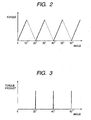
Fig. 2 is a figure showing a relationship between a rotation angle of a rotary knob provided in the present embodiment and a torque provided to the rotary knob; -
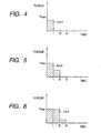
Fig. 3 is a figure showing a relationship between a rotation angle of a rotary knob provided in the present embodiment and a torque product provided to the rotary knob; -
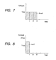
Fig. 4 is a figure showing one example on a relationship between a torque product provided to the rotary knob provided in the present embodiment and a torque and time configuring the torque product; -
Fig. 5 is a figure showing another example on a relationship between a torque product provided to the rotary knob provided in the present embodiment and a torque and time configuring the torque product; -
Fig. 6 is a figure showing still another example on a relationship between a torque product provided to the rotary knob provided in the present embodiment and a torque and time configuring the torque product; -
Fig. 7 is a figure showing one example on a relationship between a torque product and a torque and time configuring the torque product in the case of setting great a proportional multiplier for calculating a torque product to be provided to the rotary knob provided in the present embodiment; and -
Fig. 8 is a figure showing one example on a relationship between a torque product and a torque and time configuring the torque product in the case of setting great an upper limit value of torque when providing a torque product to the rotary knob provided in the present embodiment. - An embodiment of an inner-force providing input device of the present invention is explained with using the drawings.
-
Fig. 1 is a diagram showing a configuration of the present embodiment.Fig. 2 is a figure showing a relationship between a rotation angle of rotary knob provided in the embodiment and a torque delivered to the rotary knob.Fig. 3 is a figure showing a relationship between a rotation angle of the rotary knob provided in the embodiment and a torque product provided to the rotary knob. - The present embodiment has an operating member to be manually rotated, i.e.
rotary knob 1, a power-operated actuator for delivering torque to therotary knob 1, amotor 2 having an output shaft therotary knob 1 for example is fixed, rotation-angle detecting means 3 such as an encoder or potentiometer to detect a rotation angle of therotary knob 1, operating-velocity detecting means for detecting an angular velocity during operating therotary knob 1, and control means for controlling themotor 2 according to a rotation angle of therotary knob 1 detected by the rotation-angle detecting means 3 and an angular velocity detected by the operating-velocity detecting means, i.e. CPU 4. - The CPU 4 has a torque
arithmetic operating section 4d for arithmetically operating a torque to be delivered to therotary knob 1 on the basis of a rotation angle detected by the rotation-angle detecting means 3 and outputting a control signal to control themotor 2 depending upon the torque. - The torque
arithmetic operating section 4d is set, as shown by the broken line inFig. 2 , such that, while therotary knob 1 rotates from a predetermined first angle to a predetermined third angle beyond a predetermined second angle, e.g., while therotary knob 1 rotates from 10° to 30° beyond 20°, when therotary knob 1 is within a range of rotation angle of from 10° to 20°, a torque in the same direction as the rotating direction of therotary knob 1 is delivered from themotor 2 to therotary knob 1 and decreased from a maximum value to zero with an increase of rotation angle of therotary knob 1. Incidentally, the torque maximum value to be provided to therotary knob 1 is previously set depending upon the performance of themotor 2. - Meanwhile, the torque
arithmetic operating section 4d is set, as shown by the solid line in the sameFig. 2 , such that, while therotary knob 1 rotates from 10° to 30° as mentioned above, when therotary knob 1 is within a range of rotation angle of from 20° to 30°, a torque in the reverse direction to the rotating direction of therotary knob 1 is delivered from themotor 2 to therotary knob 1 and increased from zero to a maximum value with an increase of rotation angle of therotary knob 1. - Meanwhile, the torque arithmetic operating section 1d is set such that, while the
rotary knob 1 rotates from 30° to 50°, from 50° to 70°, from 70° to 90°, ... or from 350° to 370° (10°) , control is effected similarly to the control of themotor 2 of during the foregoing rotation of 10° to 30°. - Incidentally, in
Fig. 2 , the magnitude of a torque in the same direction as the rotating direction of therotary knob 1 is shown by the broken line while the magnitude of a torque in the reverse direction to the rotating direction of therotary knob 1 is shown by the solid line. Namely, inFig. 2 , torque change is represented by an absolute value. - Meanwhile, the CPU 4 has an operating-velocity
arithmetic operating section 4a for arithmetically operating an angular velocity of therotary knob 1 depending upon a change rate of rotation angle ofrotary knob 1 detected by the rotation-angle detecting means 3. Namely, the operating-velocity detecting means is formed by the rotation-angle detecting means 3 and the operating-velocityarithmetic operating section 4a. - Meanwhile, the CPU 4 has a torque-product
arithmetic operating section 4b that arithmetically operates a torque product to be provided to therotary knob 1 each time therotary knob 1 reaches 20°, 40°, 60° ... 360°, depending upon an angular velocity of therotary knob 1 calculated by the operating-velocityarithmetic operating section 4a. The torque-productarithmetic operating section 4b is set to calculate a torque product on the basis of a product of an angular velocity calculated by the operating-velocityarithmetic operating section 4a and a preset proportional multiplier. - Meanwhile, the CPU 4 has the proportional multiplier and the upper limit value of torque in providing a torque product to the
rotary knob 1, which are configured adjustable by not-shown input means. - Meanwhile, the torque
arithmetic operating section 4d is set to control themotor 2 depending upon the torque product calculated by the torque-productarithmetic operating section 4b when therotary knob 1 is detected rotated 20°, 40°, 60° ... 360°. Incidentally, because the time required for controlling themotor 2 is determined by a process speed of the CPU 4, the torquearithmetic operating section 4d is set to arithmetically operate a magnitude of torque of upon providing a torque product to therotary knob 1 and a time for which the torque is provided to therotary knob 1, on the basis of a time required for once controlling themotor 2 as a unit time. Incidentally, the time information corresponding to the unit time is to be transferred from atimer 4c provided in the CPU 4 to the torquearithmetic operating section 4d. - Herein, explanation is made as to in what way the torque of upon providing a torque product to the
rotary knob 1 and the time for which the torque is provided to therotary knob 1 are set on the basis of a torque product arithmetically operated by the torque-productarithmetic operating section 4b, by usingFigs. 4 to 6 . -
Figs. 4 to 6 are figures showing an exanmple on a relationship between a torque product provided to therotary knob 1 and a torque and time constituting the torque product. In theseFigs. 4 to 6 , a proportional multiplier is designated as k, an angular velocity is designated ω, a torque upper limit value is designated as Tmax and a unit time is designated as t. The torque product kω is an area of the hatched part shown inFig. 4 . - When ω = ω1 and kω1 ≤ Tmax • t, kω1 = T1 • t and T1 < Tmax result as shown for example in
Fig. 4 . When providing a torque product kω to therotary knob 1, a torque having a value T1 is provided to therotary knob 1 for a time t. - Meanwhile, when ω1 < ω2 and kω2 > Tmax • t, kω2 = (Tmax • t) + (T2 • t) and T2 ≤ Tmax result as shown for example in
Fig. 5 . When providing a torque product kω to therotary knob 1, a torque having a value Tmax is provided to therotary knob 1 for a time t. Thereafter, a torque having a value T2 is provided to therotary knob 1 for a time t. - Meanwhile, when ω2 < ω3, kω3 = (Tmax • t) + (Tmax • t) + (T3 • t) and T3 ≤ Tmax result as shown for example in
Fig. 6 . When providing a torque product kω to therotary knob 1, a torque having a value Tmax is provided to therotary knob 1 for atime 2t. Thereafter, a torque having a value T3 is provided to therotary knob 1 for a time t. - Next, explanation is made as to in what way the torque product to be provided to the
rotary knob 1 is changed (1) in the case of setting the proportional multiplier great and (2) in the case of setting the upper limit value of motor output torque great, by usingFigs. 7 and 8 . -
Fig. 7 is a figure showing one example on a relationship between a torque product and a torque and time constituting the torque product where the proportional multiplier for calculating a torque product to be provided to therotary knob 1 is set greater.Fig. 8 is a figure showing one example on a relationship between a torque product and a torque and time constituting the torque product where setting great the upper limit value of torque of upon providing a torque product to therotary knob 1. - For example, the upper limit value of torque is maintained at the foregoing Tmax, to increase the proportional multiplier, e.g. to 2k that is twice the foregoing. It is assumed that the
rotary knob 1 is operated at an angular velocity ω = ω2 similarly to the case inFig. 5 . In this case, the torque product to be provided to therotary knob 1 is 2kω2 that is twice the case ofFig. 5 , as shown inFig. 7 . Because the upper limit value of torque remains at Tmax, increased is the time for which torque is provided to therotary knob 1. - For example, the proportional multiplier is maintained at k, to increase the upper limit value of torque, e.g. to 2Tmax that is twice the foregoing. It is assumed that the
rotary knob 1 is operated at an angular velocity ω = ω2 similarly to the case ofFig. 5 . In this case, as shown inFig. 8 , because the proportional multiplier remains at k, the torque product is kω2 that is the same as the case ofFig. 5 . However, because the upper limit value of torque is twice, i.e., 2Tmax, a torque product in the same magnitude is provided to therotary knob 1 for a time shorter than the case ofFig. 5 . - The present embodiment thus configured operates as in the following.
- For example, it is assumed that the operator grips the
rotary knob 1 and rotates it from 10° to 30° shown inFigs. 2 and 3 . During rotation of therotary knob 1, the rotation angle of therotary knob 1 is continuously detected by the rotation-angle detecting means 3, to output a signal corresponding to a detected rotation angle to the torquearithmetic operating section 4d and operating-velocityarithmetic operating section 4a of the CPU 4. - While the
rotary knob 1 rotates from 10° to 20°, therotary knob 1 is supplied by a torque in the same direction as the rotational direction of therotary knob 1 under control of themotor 2 by the torquearithmetic operating section 4d. This torque decreases from the maximum value to zero with an increasing in rotation angle of therotary knob 1. Due to this, the operator has a feel that an urging force is delivered to therotary knob 1 while rotating therotary knob 1 from 10° to 20° whereby the urging force gradually decreases with rotation of therotary knob 1. - When the rotation-angle detecting means 3 detects that the rotation angle of the
rotary knob 1 reaches 20°, the operating-velocityarithmetic operating section 4a arithmetically operates an angular velocity of therotary knob 1 at this time on the basis of a rotation angle ofrotary knob 1 detected by the rotation-angle detecting means 3. - Then, the torque-product
arithmetic operating section 4b arithmetically operates a torque product depending upon an angular velocity ofrotary knob 1 calculated by the operating-velocityarithmetic operating section 4a. - Then, the torque
arithmetic operating section 4d arithmetically operates a torque to be provided to therotary knob 1 and a time for providing the torque to therotary knob 1, on the basis of a torque product calculated by the torque-productarithmetic operating section 4b and time information to be transferred by thetimer 4c, i.e. unit time. Depending upon a result of the calculation, themotor 2 is controlled. Due to this, a torque product is provided from themotor 2 to therotary knob 1. Accordingly, the operator obtains an impact from therotary knob 1 when the rotation angle of therotary knob 1 reaches 20°. - During rotation of the
rotary knob 1 from 20° to 30°, a torque in a reverse direction to the rotating direction of therotary knob 1 is provided from themotor 2 to therotary knob 1, under control of themotor 2 by the torquearithmetic operating section 4d. This torque increases from zero to a maximum value with an increase in rotation angle of therotary knob 1. Due to this, the operator has a feel that a resistance force is caused on therotary knob 1 during rotation of therotary knob 1 from 20° to 30° whereby the resistance force gradually increases as therotary knob 1 is rotated. - Incidentally, this embodiment operates similarly in the case that the operator rotates the
rotary knob 1 from 30° to 50° shown inFigs. 2 and 3 , from 50° to 70°, from 70° to 80° ... or from 350° to 370° (10°) . - The present embodiment obtains the following effect.
- In the present embodiment, under electric control of the
motor 2 by the CPU 4, a feel similar to that of a click mechanism is to be generated at around the time that the rotation angle of therotary knob 1 reaches 20°, 40°, 60°, 80° ... 360°. In addition, when therotary knob 1 reaches a second angle, an impact similar to that of a click mechanism can be generated, thus making it possible to generate a click feel similar to a click feel to be obtained by a click mechanism. This can generate a clear click feel. - Meanwhile, in the present embodiment, because the proportional multiplier for arithmetically operating a torque product and the torque upper limit value of upon providing a torque product to the
rotary knob 1 are each adjustable, click feel can be changed. This can set a click feel meeting the operator's preference. - Incidentally, although in the present embodiment the operating member was the
rotary knob 1, the invention is not limited to that, i.e. it may be a manipulating lever to be manually rotated. - Meanwhile, although in the present embodiment the power-operated actuator was the
motor 2, the invention is not limited to that, i.e. it is satisfactorily a power-operated actuator capable of providing a torque. - Meanwhile, although in the present embodiment the operating member was the
rotary knob 1 to be manually rotated, the invention is not limited to that. Namely, in the case to structure an inner-force providing input device having a operating member to be operated straight-line, it may be structured to provide force, in place of torque, to the operating member and impulse in place of torque product. Due to this, even in case the operating member is to be operated straight-line, a clear click feel can be provided under electric control to the operator. - As described in the above, in the present invention, under electric control of the power-operated actuator, a feel similar to that of a click mechanism is generated at around the time that the rotation angle of the operating member reaching the second angle. In addition, when the operating member reaches the second angle, an impact similar to that of a click mechanism is generated, thus making it possible to generate a click feel similar to that of a click mechanism. Due to this, a clear click feel can be generated.
- Meanwhile, in the invention, in case the control means includes a torque product arithmetic operating section for arithmetically operating the torque product according to a product of the angular velocity arithmetically operated by the operation-velocity arithmetic operating section and a preset proportional multiplier, wherein the torque product is configured to adjust an upper limit value of torque of upon providing the torque product to the operating member and the proportional multiplier, the click feel can be changed. This can make it possible to set a click feel meeting the operator's preference.
- Meanwhile, the invention was the inner-force providing input device having the operating member to be manually rotated. In the case to configure an inner-force providing input device having an operating member to be operated straight-line manually, it is satisfactory to configure such that a force in place of a torque and an impulse in place of a torque product are provided to the operating member. Due to this, even in case the operating member is to be operated straight-line manually, a click feel similar to that of click mechanism can be generated under electric control. This can generate a clear click feel.
Claims (4)
- An inner-force providing input device comprising:an operating member (1) to be manually rotated;a power-operated actuator (2) for providing a torque to the operating member (1);rotation angle detecting means (3) for detecting a rotation angle of the operating member (1);operating velocity detecting means (4a) for detecting an angular velocity of the operating member (1); andcontrol means for controlling the power-operated actuator (2) depending upon an rotation angle detected by the rotation angle detecting means (3) and an angular velocity detected by the operating velocity detecting means (4a);wherein the control means is set such that, while the operating member rotates from a predetermined first angle to a predetermined third angle beyond a predetermined second angle, when the operating member (1) is within a range of from the first angle to the second angle, a torque in a same direction as a rotating direction of the operating member is provided from the power-operated actuator (2) to the operating member (1) and decreased with an increase in rotation angle of the operating member (1), andwhen the operating member is within a range of from the second angle to the third angle, a torque in a reverse direction to a rotating direction of the operating member (1) is provided from the power-operated actuator to the operating member and increased with an increase in rotation angle of the operating member,characterized in thatthe control means is further set such that, when the operating member (1) reaches the second angle,
a torque product value is calculated as a product of the angular
velocity of the operating member (1) detected at this time by the operating velocity detecting means (4a) and a preset proportional multiplier,
an impact torque and a provision time for the impact torque are set on the basis of the calculated torque product value, wherein:the impact torque is provided over the provision time from the power-operated actuator to the operating member in a reverse direction to a rotation direction of the operating member (1). - An inner-force providing input device according to claim 1, wherein the operating velocity detecting means comprises the rotation angle detecting means and an operating velocity arithmetic operating section (4b) for arithmetically operating an angular velocity of the operating member on the basis of a rotation angle change of the operating member detected by the rotation angle detecting means, the operating velocity arithmetic operating section being included in the control means.
- An inner-force providing input device according to claim 2, wherein the control means includes a torque product arithmetic operating section for arithmetically operating the torque product according to a product of the angular velocity arithmetically operated by the operation velocity arithmetic-operating section and a preset proportional multiplier, to adjustably configure an upper limit value of torque upon providing the torque product to the operating member and the proportional multiplier.
- An inner-force providing input device comprising:an operating member to be manually operated straight-line;a power-operated actuator for providing a force to the operating member;position detecting means for detecting a position of the operating member;operating velocity detecting means for detecting a moving velocity of the operating member; andcontrol means for controlling the power-operated actuator depending upon a position detected by the position detecting means and a moving velocity detected by the operating velocity detecting means;wherein the control means is set such that, while the operating member moves from a predetermined first position to a predetermined third position beyond a predetermined second position, when the operating member is within a range of from the first position to the second position, a force in a same direction as a moving direction of the operating member is provided from the power-operated actuator to the operating member and decreased with an increase in moving distance of the operating member, andwhen the operating member is within a range of from the second position to the third position, a force in a reverse direction to a moving direction of the operating member is provided from the power-operated actuator to the operating member and increased with an increase in moving distance of the operating member, characterized in thatthe control means is further set such that, when the operating member reaches the second position,
an impulse value is calculated as a product of the moving velocity of the operating member detected at this time by the operating velocity detecting means and a preset proportional multiplier,
an impact force and a provision time for the impact force are set on the basis of the calculated impulse value, wherein:the impact force is provided over the provision time from the power-operated actuator to the operating member in a reverse direction to a moving direction of the operating member.the provision time consists of one or more unit time intervals,an individual magnitude of the impact torque is set for each of the unit time intervals,the individual magnitude of the impact torque is constant and equal to or smaller than a maximum torque value during each of the unit time intervals,the individual magnitude of the impact torque is set to the maximum torque value for all but the last unit time intervals, andthe individual magnitude of the impact torque for the last unit time interval is set to such a value that the sum of the individual magnitudes of the impact torque of all unit time intervals, multiplied by the duration of one unit time interval, equals the calculated torque product value, andthe provision time consists of one or more unit time intervals,an individual magnitude of the impact force is set for each of the unit time intervals,the individual magnitude of the impact force is constant and equal to or smaller than a maximum force value during each of the unit time intervals,the individual magnitude of the impact force is set to the maximum force value for all but the last unit time intervals, andthe individual magnitude of the impact force for the last unit time interval is set to such:a value that the sum of the individual magnitudes of the impact force of all unit time intervals, multiplied by the duration of one unit time interval, equals the calculated impulse value, and
Applications Claiming Priority (2)
| Application Number | Priority Date | Filing Date | Title |
|---|---|---|---|
| JP2002279101A JP4118114B2 (en) | 2002-09-25 | 2002-09-25 | Force sense input device |
| JP2002279101 | 2002-09-25 |
Publications (3)
| Publication Number | Publication Date |
|---|---|
| EP1406152A2 EP1406152A2 (en) | 2004-04-07 |
| EP1406152A3 EP1406152A3 (en) | 2006-01-11 |
| EP1406152B1 true EP1406152B1 (en) | 2015-05-20 |
Family
ID=31987083
Family Applications (1)
| Application Number | Title | Priority Date | Filing Date |
|---|---|---|---|
| EP20030021497 Expired - Fee Related EP1406152B1 (en) | 2002-09-25 | 2003-09-23 | Inner-force providing input device having a power-operated actuator for generating a click feel |
Country Status (3)
| Country | Link |
|---|---|
| US (1) | US6838851B2 (en) |
| EP (1) | EP1406152B1 (en) |
| JP (1) | JP4118114B2 (en) |
Families Citing this family (25)
| Publication number | Priority date | Publication date | Assignee | Title |
|---|---|---|---|---|
| JP4058938B2 (en) * | 2001-12-03 | 2008-03-12 | 日産自動車株式会社 | Rotary input device |
| JP4209235B2 (en) * | 2003-03-28 | 2009-01-14 | アルプス電気株式会社 | Haptic input device |
| US8030871B1 (en) | 2003-11-26 | 2011-10-04 | Liontech Trains Llc | Model train control system having realistic speed control |
| US8013550B1 (en) | 2003-11-26 | 2011-09-06 | Liontech Trains Llc | Model train remote control system having realistic speed and special effects control |
| US8154227B1 (en) | 2003-11-26 | 2012-04-10 | Liontech Trains Llc | Model train control system |
| US7312590B1 (en) * | 2003-11-26 | 2007-12-25 | The Creative Train Company, Llc | Model railroad velocity controller |
| DE102004016121B4 (en) * | 2004-04-01 | 2008-11-27 | Siemens Ag | Operating device for moving at least one machine axis of a tool or production machine |
| JP4430988B2 (en) | 2004-06-24 | 2010-03-10 | アルプス電気株式会社 | Haptic input device |
| FR2881268B1 (en) * | 2005-01-26 | 2007-04-06 | Bosch Rexroth D S I Soc Par Ac | ROTARY CONTROL DEVICE |
| US7518745B2 (en) * | 2005-09-28 | 2009-04-14 | Xerox Corporation | Imaging system with haptic interface |
| US20090308199A1 (en) * | 2008-06-12 | 2009-12-17 | Thomas John Buckingham | Rotary actuating mechanism having a selectable torque |
| JP5574523B2 (en) * | 2009-04-22 | 2014-08-20 | 株式会社プロテックデザイン | Rotary input device and electronic device |
| US20110115754A1 (en) * | 2009-11-17 | 2011-05-19 | Immersion Corporation | Systems and Methods For A Friction Rotary Device For Haptic Feedback |
| JP6005950B2 (en) | 2011-08-04 | 2016-10-12 | オリンパス株式会社 | Surgery support apparatus and control method thereof |
| EP2740434A4 (en) | 2011-08-04 | 2015-03-18 | Olympus Corp | Medical manipulator and method for controlling same |
| JP5953058B2 (en) | 2011-08-04 | 2016-07-13 | オリンパス株式会社 | Surgery support device and method for attaching and detaching the same |
| JP5931497B2 (en) | 2011-08-04 | 2016-06-08 | オリンパス株式会社 | Surgery support apparatus and assembly method thereof |
| JP5936914B2 (en) | 2011-08-04 | 2016-06-22 | オリンパス株式会社 | Operation input device and manipulator system including the same |
| JP6009840B2 (en) | 2011-08-04 | 2016-10-19 | オリンパス株式会社 | Medical equipment |
| JP6021484B2 (en) | 2011-08-04 | 2016-11-09 | オリンパス株式会社 | Medical manipulator |
| JP6081061B2 (en) | 2011-08-04 | 2017-02-15 | オリンパス株式会社 | Surgery support device |
| US9519341B2 (en) | 2011-08-04 | 2016-12-13 | Olympus Corporation | Medical manipulator and surgical support apparatus |
| JP6761486B2 (en) * | 2017-01-20 | 2020-09-23 | アルプスアルパイン株式会社 | Rotational operation device, control method of rotary operation device, and control program of rotary operation device |
| JP6896068B2 (en) * | 2017-04-21 | 2021-06-30 | アルプスアルパイン株式会社 | Rotary operating device and its control method and program |
| WO2018193981A1 (en) | 2017-04-21 | 2018-10-25 | アルプス電気株式会社 | Rotary-type operation device, method for controlling same, and program |
Citations (1)
| Publication number | Priority date | Publication date | Assignee | Title |
|---|---|---|---|---|
| US5629594A (en) * | 1992-12-02 | 1997-05-13 | Cybernet Systems Corporation | Force feedback system |
Family Cites Families (9)
| Publication number | Priority date | Publication date | Assignee | Title |
|---|---|---|---|---|
| JPS5797591A (en) * | 1980-12-10 | 1982-06-17 | Nippon Musical Instruments Mfg | Preset device for electronic musical instrument |
| US5220260A (en) * | 1991-10-24 | 1993-06-15 | Lex Computer And Management Corporation | Actuator having electronically controllable tactile responsiveness |
| DE4205875A1 (en) * | 1992-02-26 | 1993-09-02 | Vdo Schindling | Rotary selector e.g. for manual input of data in to electronic equipment - has movement of rotary input knob controlled by motor and generator with positions defined by load data in memory |
| DE19528457C2 (en) * | 1995-08-03 | 2001-03-08 | Mannesmann Vdo Ag | Control device |
| US5959613A (en) | 1995-12-01 | 1999-09-28 | Immersion Corporation | Method and apparatus for shaping force signals for a force feedback device |
| US6147674A (en) * | 1995-12-01 | 2000-11-14 | Immersion Corporation | Method and apparatus for designing force sensations in force feedback computer applications |
| US6154201A (en) * | 1996-11-26 | 2000-11-28 | Immersion Corporation | Control knob with multiple degrees of freedom and force feedback |
| US6636197B1 (en) * | 1996-11-26 | 2003-10-21 | Immersion Corporation | Haptic feedback effects for control, knobs and other interface devices |
| US6686911B1 (en) * | 1996-11-26 | 2004-02-03 | Immersion Corporation | Control knob with control modes and force feedback |
-
2002
- 2002-09-25 JP JP2002279101A patent/JP4118114B2/en not_active Expired - Fee Related
-
2003
- 2003-09-17 US US10/664,770 patent/US6838851B2/en not_active Expired - Lifetime
- 2003-09-23 EP EP20030021497 patent/EP1406152B1/en not_active Expired - Fee Related
Patent Citations (1)
| Publication number | Priority date | Publication date | Assignee | Title |
|---|---|---|---|---|
| US5629594A (en) * | 1992-12-02 | 1997-05-13 | Cybernet Systems Corporation | Force feedback system |
Non-Patent Citations (2)
| Title |
|---|
| MILLMAN P.A.; COLGATE J.E.: "EFFECTS OF NON-UNIFORM ENVIRONMENT DAMPING ON HAPTIC PERCEPTION ANDPERFORMANCE OF AIMED MOVEMENTS", PROCEEDINGS OF THE ASME DYNAMIC SYSTEMS AND CONTROL DIVISION, 1995, SAN FRANCISCO, pages 703 - 712, XP007915540, Retrieved from the Internet <URL:http://www.mech.northwestern.edu/colgate/> [retrieved on 20100708] * |
| ROSENBERG L.B. ET AL: "Perceptual decomposition of virtual haptic surfaces", VIRTUAL REALITY, 1993. PROCEEDINGS., IEEE 1993 SYMPOSIUM ON RESEARCH F RONTIERS IN SAN JOSE, CA, USA 25-26 OCT. 1993, LOS ALAMITOS, CA, USA,IEEE COMPUT. SOC, LOS ALAMITOS, CA, USA, 25 October 1993 (1993-10-25), pages 46 - 53, XP031559114, ISBN: 978-0-8186-4910-3 * |
Also Published As
| Publication number | Publication date |
|---|---|
| JP4118114B2 (en) | 2008-07-16 |
| US6838851B2 (en) | 2005-01-04 |
| EP1406152A3 (en) | 2006-01-11 |
| JP2004114201A (en) | 2004-04-15 |
| US20040056624A1 (en) | 2004-03-25 |
| EP1406152A2 (en) | 2004-04-07 |
Similar Documents
| Publication | Publication Date | Title |
|---|---|---|
| EP1406152B1 (en) | Inner-force providing input device having a power-operated actuator for generating a click feel | |
| US20220241684A1 (en) | Information processing system, operation device, and operation device control method | |
| US7359778B2 (en) | Vehicle steering apparatus | |
| JP2008001117A (en) | Steering device of vehicle | |
| JP2007137287A (en) | Steering device of vehicle | |
| EP3050676B1 (en) | Power hand tool with enhanced feedback | |
| EP1450231B1 (en) | Force-applying input device | |
| EP1610207B1 (en) | Haptic feedback input device | |
| JP4143437B2 (en) | Haptic input device | |
| JP4446712B2 (en) | Haptic input device | |
| EP1411405A2 (en) | Force imparting apparatus | |
| JP7216708B2 (en) | controller for industrial machines | |
| JP2004224159A (en) | Steering control device for vehicle | |
| KR20150077988A (en) | Control device for MDPS and control method for MDPS using of the same | |
| JP2004302529A (en) | Haptic force feedback device | |
| JP2003150261A (en) | Dumper force applying operation controller | |
| JP2003122435A (en) | Apparatus for imparting and inputting inner force sense | |
| EP3036595B1 (en) | Tactile feel control device | |
| JP2006069351A (en) | Steering device for vehicle | |
| JP4280695B2 (en) | Vehicle steering device | |
| JP4206511B2 (en) | Rotary encoder device | |
| JP4176057B2 (en) | Vehicle steering device | |
| JP4176042B2 (en) | Vehicle steering device | |
| WO2016017839A1 (en) | Engine rpm override control device | |
| JPS62218244A (en) | Continuously variable transmission controller for vehicle |
Legal Events
| Date | Code | Title | Description |
|---|---|---|---|
| PUAI | Public reference made under article 153(3) epc to a published international application that has entered the european phase |
Free format text: ORIGINAL CODE: 0009012 |
|
| AK | Designated contracting states |
Kind code of ref document: A2 Designated state(s): AT BE BG CH CY CZ DE DK EE ES FI FR GB GR HU IE IT LI LU MC NL PT RO SE SI SK TR |
|
| AX | Request for extension of the european patent |
Extension state: AL LT LV MK |
|
| PUAL | Search report despatched |
Free format text: ORIGINAL CODE: 0009013 |
|
| AK | Designated contracting states |
Kind code of ref document: A3 Designated state(s): AT BE BG CH CY CZ DE DK EE ES FI FR GB GR HU IE IT LI LU MC NL PT RO SE SI SK TR |
|
| AX | Request for extension of the european patent |
Extension state: AL LT LV MK |
|
| 17P | Request for examination filed |
Effective date: 20051228 |
|
| AKX | Designation fees paid |
Designated state(s): DE FR GB |
|
| APBK | Appeal reference recorded |
Free format text: ORIGINAL CODE: EPIDOSNREFNE |
|
| APBN | Date of receipt of notice of appeal recorded |
Free format text: ORIGINAL CODE: EPIDOSNNOA2E |
|
| APBR | Date of receipt of statement of grounds of appeal recorded |
Free format text: ORIGINAL CODE: EPIDOSNNOA3E |
|
| APAF | Appeal reference modified |
Free format text: ORIGINAL CODE: EPIDOSCREFNE |
|
| APBT | Appeal procedure closed |
Free format text: ORIGINAL CODE: EPIDOSNNOA9E |
|
| GRAP | Despatch of communication of intention to grant a patent |
Free format text: ORIGINAL CODE: EPIDOSNIGR1 |
|
| INTG | Intention to grant announced |
Effective date: 20141201 |
|
| GRAS | Grant fee paid |
Free format text: ORIGINAL CODE: EPIDOSNIGR3 |
|
| GRAA | (expected) grant |
Free format text: ORIGINAL CODE: 0009210 |
|
| AK | Designated contracting states |
Kind code of ref document: B1 Designated state(s): DE FR GB |
|
| REG | Reference to a national code |
Ref country code: GB Ref legal event code: FG4D |
|
| REG | Reference to a national code |
Ref country code: DE Ref legal event code: R096 Ref document number: 60347629 Country of ref document: DE |
|
| REG | Reference to a national code |
Ref country code: DE Ref legal event code: R097 Ref document number: 60347629 Country of ref document: DE |
|
| PLBE | No opposition filed within time limit |
Free format text: ORIGINAL CODE: 0009261 |
|
| STAA | Information on the status of an ep patent application or granted ep patent |
Free format text: STATUS: NO OPPOSITION FILED WITHIN TIME LIMIT |
|
| 26N | No opposition filed |
Effective date: 20160223 |
|
| GBPC | Gb: european patent ceased through non-payment of renewal fee |
Effective date: 20150923 |
|
| REG | Reference to a national code |
Ref country code: FR Ref legal event code: ST Effective date: 20160531 |
|
| PG25 | Lapsed in a contracting state [announced via postgrant information from national office to epo] |
Ref country code: GB Free format text: LAPSE BECAUSE OF NON-PAYMENT OF DUE FEES Effective date: 20150923 |
|
| PG25 | Lapsed in a contracting state [announced via postgrant information from national office to epo] |
Ref country code: FR Free format text: LAPSE BECAUSE OF NON-PAYMENT OF DUE FEES Effective date: 20150930 |
|
| REG | Reference to a national code |
Ref country code: DE Ref legal event code: R082 Ref document number: 60347629 Country of ref document: DE Representative=s name: SCHMITT-NILSON SCHRAUD WAIBEL WOHLFROM PATENTA, DE |
|
| REG | Reference to a national code |
Ref country code: DE Ref legal event code: R082 Ref document number: 60347629 Country of ref document: DE Representative=s name: SCHMITT-NILSON SCHRAUD WAIBEL WOHLFROM PATENTA, DE Ref country code: DE Ref legal event code: R081 Ref document number: 60347629 Country of ref document: DE Owner name: ALPS ALPINE CO., LTD., JP Free format text: FORMER OWNER: ALPS ELECTRIC CO., LTD., TOKIO/TOKYO, JP |
|
| PGFP | Annual fee paid to national office [announced via postgrant information from national office to epo] |
Ref country code: DE Payment date: 20190918 Year of fee payment: 17 |
|
| REG | Reference to a national code |
Ref country code: DE Ref legal event code: R119 Ref document number: 60347629 Country of ref document: DE |
|
| PG25 | Lapsed in a contracting state [announced via postgrant information from national office to epo] |
Ref country code: DE Free format text: LAPSE BECAUSE OF NON-PAYMENT OF DUE FEES Effective date: 20210401 |