EP1403355A1 - Phosphor blends and blacklight sources for liquid crystal displays - Google Patents
Phosphor blends and blacklight sources for liquid crystal displays Download PDFInfo
- Publication number
- EP1403355A1 EP1403355A1 EP20030255943 EP03255943A EP1403355A1 EP 1403355 A1 EP1403355 A1 EP 1403355A1 EP 20030255943 EP20030255943 EP 20030255943 EP 03255943 A EP03255943 A EP 03255943A EP 1403355 A1 EP1403355 A1 EP 1403355A1
- Authority
- EP
- European Patent Office
- Prior art keywords
- light
- phosphor
- spectrum
- liquid crystal
- mixtures
- Prior art date
- Legal status (The legal status is an assumption and is not a legal conclusion. Google has not performed a legal analysis and makes no representation as to the accuracy of the status listed.)
- Withdrawn
Links
- OAICVXFJPJFONN-UHFFFAOYSA-N Phosphorus Chemical compound [P] OAICVXFJPJFONN-UHFFFAOYSA-N 0.000 title claims abstract description 111
- 239000000203 mixture Substances 0.000 title claims abstract description 94
- 239000004973 liquid crystal related substance Substances 0.000 title claims abstract description 45
- 238000001429 visible spectrum Methods 0.000 claims abstract description 7
- 229910052712 strontium Inorganic materials 0.000 claims description 75
- 229910052791 calcium Inorganic materials 0.000 claims description 56
- 239000000463 material Substances 0.000 claims description 33
- YBMRDBCBODYGJE-UHFFFAOYSA-N germanium dioxide Chemical compound O=[Ge]=O YBMRDBCBODYGJE-UHFFFAOYSA-N 0.000 claims description 32
- 238000001228 spectrum Methods 0.000 claims description 30
- 229910052725 zinc Inorganic materials 0.000 claims description 27
- 229910052727 yttrium Inorganic materials 0.000 claims description 24
- 229910052749 magnesium Inorganic materials 0.000 claims description 23
- 229910052909 inorganic silicate Inorganic materials 0.000 claims description 19
- 229910052688 Gadolinium Inorganic materials 0.000 claims description 16
- 229910052733 gallium Inorganic materials 0.000 claims description 16
- 229910052738 indium Inorganic materials 0.000 claims description 16
- 229910052788 barium Inorganic materials 0.000 claims description 11
- 229910017623 MgSi2 Inorganic materials 0.000 claims description 8
- 239000005084 Strontium aluminate Substances 0.000 claims description 8
- 229910052771 Terbium Inorganic materials 0.000 claims description 8
- 229910052746 lanthanum Inorganic materials 0.000 claims description 8
- 239000004065 semiconductor Substances 0.000 abstract description 3
- 239000010410 layer Substances 0.000 description 37
- -1 poly(cyclic olefins Chemical class 0.000 description 21
- 239000011701 zinc Substances 0.000 description 18
- 238000006243 chemical reaction Methods 0.000 description 15
- 229920000642 polymer Polymers 0.000 description 11
- 229920005989 resin Polymers 0.000 description 11
- 239000011347 resin Substances 0.000 description 11
- 239000002245 particle Substances 0.000 description 7
- 230000005670 electromagnetic radiation Effects 0.000 description 6
- 238000000295 emission spectrum Methods 0.000 description 6
- 229910052751 metal Inorganic materials 0.000 description 6
- 239000002184 metal Substances 0.000 description 6
- 238000000576 coating method Methods 0.000 description 5
- 238000009792 diffusion process Methods 0.000 description 5
- 239000003822 epoxy resin Substances 0.000 description 5
- LNEPOXFFQSENCJ-UHFFFAOYSA-N haloperidol Chemical compound C1CC(O)(C=2C=CC(Cl)=CC=2)CCN1CCCC(=O)C1=CC=C(F)C=C1 LNEPOXFFQSENCJ-UHFFFAOYSA-N 0.000 description 5
- 229920000548 poly(silane) polymer Polymers 0.000 description 5
- 229920000647 polyepoxide Polymers 0.000 description 5
- 238000000149 argon plasma sintering Methods 0.000 description 4
- 230000004888 barrier function Effects 0.000 description 4
- 239000011248 coating agent Substances 0.000 description 4
- 229920001577 copolymer Polymers 0.000 description 4
- 239000010408 film Substances 0.000 description 4
- 239000011159 matrix material Substances 0.000 description 4
- 229920003023 plastic Polymers 0.000 description 4
- 229920001296 polysiloxane Polymers 0.000 description 4
- NIXOWILDQLNWCW-UHFFFAOYSA-M Acrylate Chemical compound [O-]C(=O)C=C NIXOWILDQLNWCW-UHFFFAOYSA-M 0.000 description 3
- 239000004593 Epoxy Substances 0.000 description 3
- 239000011521 glass Substances 0.000 description 3
- 239000011368 organic material Substances 0.000 description 3
- 239000004033 plastic Substances 0.000 description 3
- 229910019901 yttrium aluminum garnet Inorganic materials 0.000 description 3
- GWEVSGVZZGPLCZ-UHFFFAOYSA-N Titan oxide Chemical compound O=[Ti]=O GWEVSGVZZGPLCZ-UHFFFAOYSA-N 0.000 description 2
- XLOMVQKBTHCTTD-UHFFFAOYSA-N Zinc monoxide Chemical compound [Zn]=O XLOMVQKBTHCTTD-UHFFFAOYSA-N 0.000 description 2
- 239000002253 acid Substances 0.000 description 2
- MWPLVEDNUUSJAV-UHFFFAOYSA-N anthracene Chemical compound C1=CC=CC2=CC3=CC=CC=C3C=C21 MWPLVEDNUUSJAV-UHFFFAOYSA-N 0.000 description 2
- 125000003118 aryl group Chemical group 0.000 description 2
- 230000005540 biological transmission Effects 0.000 description 2
- 238000005266 casting Methods 0.000 description 2
- VPUGDVKSAQVFFS-UHFFFAOYSA-N coronene Chemical compound C1=C(C2=C34)C=CC3=CC=C(C=C3)C4=C4C3=CC=C(C=C3)C4=C2C3=C1 VPUGDVKSAQVFFS-UHFFFAOYSA-N 0.000 description 2
- LEQAOMBKQFMDFZ-UHFFFAOYSA-N glyoxal Chemical compound O=CC=O LEQAOMBKQFMDFZ-UHFFFAOYSA-N 0.000 description 2
- 229910010272 inorganic material Inorganic materials 0.000 description 2
- 239000011147 inorganic material Substances 0.000 description 2
- UHOVQNZJYSORNB-UHFFFAOYSA-N monobenzene Natural products C1=CC=CC=C1 UHOVQNZJYSORNB-UHFFFAOYSA-N 0.000 description 2
- 229920000620 organic polymer Polymers 0.000 description 2
- 229920003227 poly(N-vinyl carbazole) Polymers 0.000 description 2
- 229920000058 polyacrylate Polymers 0.000 description 2
- 229920000139 polyethylene terephthalate Polymers 0.000 description 2
- 239000000758 substrate Substances 0.000 description 2
- ZVYYAYJIGYODSD-LNTINUHCSA-K (z)-4-bis[[(z)-4-oxopent-2-en-2-yl]oxy]gallanyloxypent-3-en-2-one Chemical compound [Ga+3].C\C([O-])=C\C(C)=O.C\C([O-])=C\C(C)=O.C\C([O-])=C\C(C)=O ZVYYAYJIGYODSD-LNTINUHCSA-K 0.000 description 1
- POILWHVDKZOXJZ-ARJAWSKDSA-M (z)-4-oxopent-2-en-2-olate Chemical compound C\C([O-])=C\C(C)=O POILWHVDKZOXJZ-ARJAWSKDSA-M 0.000 description 1
- KLCLIOISYBHYDZ-UHFFFAOYSA-N 1,4,4-triphenylbuta-1,3-dienylbenzene Chemical compound C=1C=CC=CC=1C(C=1C=CC=CC=1)=CC=C(C=1C=CC=CC=1)C1=CC=CC=C1 KLCLIOISYBHYDZ-UHFFFAOYSA-N 0.000 description 1
- BRSRUYVJULRMRQ-UHFFFAOYSA-N 1-phenylanthracene Chemical compound C1=CC=CC=C1C1=CC=CC2=CC3=CC=CC=C3C=C12 BRSRUYVJULRMRQ-UHFFFAOYSA-N 0.000 description 1
- SMZOUWXMTYCWNB-UHFFFAOYSA-N 2-(2-methoxy-5-methylphenyl)ethanamine Chemical compound COC1=CC=C(C)C=C1CCN SMZOUWXMTYCWNB-UHFFFAOYSA-N 0.000 description 1
- NIXOWILDQLNWCW-UHFFFAOYSA-N 2-Propenoic acid Natural products OC(=O)C=C NIXOWILDQLNWCW-UHFFFAOYSA-N 0.000 description 1
- GOLORTLGFDVFDW-UHFFFAOYSA-N 3-(1h-benzimidazol-2-yl)-7-(diethylamino)chromen-2-one Chemical compound C1=CC=C2NC(C3=CC4=CC=C(C=C4OC3=O)N(CC)CC)=NC2=C1 GOLORTLGFDVFDW-UHFFFAOYSA-N 0.000 description 1
- IMROMDMJAWUWLK-UHFFFAOYSA-N Ethenol Chemical compound OC=C IMROMDMJAWUWLK-UHFFFAOYSA-N 0.000 description 1
- CERQOIWHTDAKMF-UHFFFAOYSA-N Methacrylic acid Chemical compound CC(=C)C(O)=O CERQOIWHTDAKMF-UHFFFAOYSA-N 0.000 description 1
- 239000004988 Nematic liquid crystal Substances 0.000 description 1
- 229920000286 Poly(2-decyloxy-1,4-phenylene) Polymers 0.000 description 1
- 239000004695 Polyether sulfone Substances 0.000 description 1
- 239000004697 Polyetherimide Substances 0.000 description 1
- 239000004642 Polyimide Substances 0.000 description 1
- 229920001328 Polyvinylidene chloride Polymers 0.000 description 1
- BLRPTPMANUNPDV-UHFFFAOYSA-N Silane Chemical compound [SiH4] BLRPTPMANUNPDV-UHFFFAOYSA-N 0.000 description 1
- NINIDFKCEFEMDL-UHFFFAOYSA-N Sulfur Chemical compound [S] NINIDFKCEFEMDL-UHFFFAOYSA-N 0.000 description 1
- 239000007983 Tris buffer Substances 0.000 description 1
- 150000007513 acids Chemical class 0.000 description 1
- 125000000217 alkyl group Chemical group 0.000 description 1
- AZDRQVAHHNSJOQ-UHFFFAOYSA-N alumane Chemical compound [AlH3] AZDRQVAHHNSJOQ-UHFFFAOYSA-N 0.000 description 1
- PNEYBMLMFCGWSK-UHFFFAOYSA-N aluminium oxide Inorganic materials [O-2].[O-2].[O-2].[Al+3].[Al+3] PNEYBMLMFCGWSK-UHFFFAOYSA-N 0.000 description 1
- 125000002490 anilino group Chemical group [H]N(*)C1=C([H])C([H])=C([H])C([H])=C1[H] 0.000 description 1
- QVGXLLKOCUKJST-UHFFFAOYSA-N atomic oxygen Chemical compound [O] QVGXLLKOCUKJST-UHFFFAOYSA-N 0.000 description 1
- BEQNOZDXPONEMR-UHFFFAOYSA-N cadmium;oxotin Chemical compound [Cd].[Sn]=O BEQNOZDXPONEMR-UHFFFAOYSA-N 0.000 description 1
- 230000001413 cellular effect Effects 0.000 description 1
- 239000002800 charge carrier Substances 0.000 description 1
- 239000013626 chemical specie Substances 0.000 description 1
- 238000005229 chemical vapour deposition Methods 0.000 description 1
- 239000002131 composite material Substances 0.000 description 1
- 150000001875 compounds Chemical class 0.000 description 1
- 229910052593 corundum Inorganic materials 0.000 description 1
- 150000001925 cycloalkenes Chemical class 0.000 description 1
- 230000007547 defect Effects 0.000 description 1
- 230000005684 electric field Effects 0.000 description 1
- 238000005401 electroluminescence Methods 0.000 description 1
- 238000005516 engineering process Methods 0.000 description 1
- 150000002148 esters Chemical class 0.000 description 1
- 239000007789 gas Substances 0.000 description 1
- 229940015043 glyoxal Drugs 0.000 description 1
- SKWCWFYBFZIXHE-UHFFFAOYSA-K indium acetylacetonate Chemical compound CC(=O)C=C(C)O[In](OC(C)=CC(C)=O)OC(C)=CC(C)=O SKWCWFYBFZIXHE-UHFFFAOYSA-K 0.000 description 1
- 229910003437 indium oxide Inorganic materials 0.000 description 1
- PJXISJQVUVHSOJ-UHFFFAOYSA-N indium(iii) oxide Chemical compound [O-2].[O-2].[O-2].[In+3].[In+3] PJXISJQVUVHSOJ-UHFFFAOYSA-N 0.000 description 1
- AMGQUBHHOARCQH-UHFFFAOYSA-N indium;oxotin Chemical compound [In].[Sn]=O AMGQUBHHOARCQH-UHFFFAOYSA-N 0.000 description 1
- 238000007735 ion beam assisted deposition Methods 0.000 description 1
- 238000001659 ion-beam spectroscopy Methods 0.000 description 1
- 238000004519 manufacturing process Methods 0.000 description 1
- 238000010297 mechanical methods and process Methods 0.000 description 1
- 150000001247 metal acetylides Chemical class 0.000 description 1
- 229910044991 metal oxide Inorganic materials 0.000 description 1
- 150000004706 metal oxides Chemical class 0.000 description 1
- 150000002739 metals Chemical class 0.000 description 1
- 238000000034 method Methods 0.000 description 1
- 238000002156 mixing Methods 0.000 description 1
- 150000004767 nitrides Chemical class 0.000 description 1
- 239000006250 one-dimensional material Substances 0.000 description 1
- 239000012044 organic layer Substances 0.000 description 1
- 229910052760 oxygen Inorganic materials 0.000 description 1
- 239000001301 oxygen Substances 0.000 description 1
- 125000002080 perylenyl group Chemical group C1(=CC=C2C=CC=C3C4=CC=CC5=CC=CC(C1=C23)=C45)* 0.000 description 1
- CSHWQDPOILHKBI-UHFFFAOYSA-N peryrene Natural products C1=CC(C2=CC=CC=3C2=C2C=CC=3)=C3C2=CC=CC3=C1 CSHWQDPOILHKBI-UHFFFAOYSA-N 0.000 description 1
- ISWSIDIOOBJBQZ-UHFFFAOYSA-M phenolate Chemical compound [O-]C1=CC=CC=C1 ISWSIDIOOBJBQZ-UHFFFAOYSA-M 0.000 description 1
- 238000005240 physical vapour deposition Methods 0.000 description 1
- 238000000623 plasma-assisted chemical vapour deposition Methods 0.000 description 1
- 229920003208 poly(ethylene sulfide) Polymers 0.000 description 1
- 229920003207 poly(ethylene-2,6-naphthalate) Polymers 0.000 description 1
- 229920000052 poly(p-xylylene) Polymers 0.000 description 1
- 229920000515 polycarbonate Polymers 0.000 description 1
- 239000004417 polycarbonate Substances 0.000 description 1
- 229920000728 polyester Polymers 0.000 description 1
- 229920006393 polyether sulfone Polymers 0.000 description 1
- 229920001601 polyetherimide Polymers 0.000 description 1
- 239000011112 polyethylene naphthalate Substances 0.000 description 1
- 229920001721 polyimide Polymers 0.000 description 1
- 229920002451 polyvinyl alcohol Polymers 0.000 description 1
- 229920002620 polyvinyl fluoride Polymers 0.000 description 1
- 239000011241 protective layer Substances 0.000 description 1
- 230000005855 radiation Effects 0.000 description 1
- 238000005096 rolling process Methods 0.000 description 1
- YYMBJDOZVAITBP-UHFFFAOYSA-N rubrene Chemical compound C1=CC=CC=C1C(C1=C(C=2C=CC=CC=2)C2=CC=CC=C2C(C=2C=CC=CC=2)=C11)=C(C=CC=C2)C2=C1C1=CC=CC=C1 YYMBJDOZVAITBP-UHFFFAOYSA-N 0.000 description 1
- 229910000077 silane Inorganic materials 0.000 description 1
- 239000007787 solid Substances 0.000 description 1
- 238000005507 spraying Methods 0.000 description 1
- 238000003892 spreading Methods 0.000 description 1
- 238000003756 stirring Methods 0.000 description 1
- 239000000126 substance Substances 0.000 description 1
- 229910052717 sulfur Inorganic materials 0.000 description 1
- 239000011593 sulfur Substances 0.000 description 1
- 239000010409 thin film Substances 0.000 description 1
- XOLBLPGZBRYERU-UHFFFAOYSA-N tin dioxide Chemical compound O=[Sn]=O XOLBLPGZBRYERU-UHFFFAOYSA-N 0.000 description 1
- 229910001887 tin oxide Inorganic materials 0.000 description 1
- XLYOFNOQVPJJNP-UHFFFAOYSA-N water Chemical compound O XLYOFNOQVPJJNP-UHFFFAOYSA-N 0.000 description 1
- 229910001845 yogo sapphire Inorganic materials 0.000 description 1
- YVTHLONGBIQYBO-UHFFFAOYSA-N zinc indium(3+) oxygen(2-) Chemical compound [O--].[Zn++].[In+3] YVTHLONGBIQYBO-UHFFFAOYSA-N 0.000 description 1
- 239000011787 zinc oxide Substances 0.000 description 1
Images


Classifications
-
- C—CHEMISTRY; METALLURGY
- C09—DYES; PAINTS; POLISHES; NATURAL RESINS; ADHESIVES; COMPOSITIONS NOT OTHERWISE PROVIDED FOR; APPLICATIONS OF MATERIALS NOT OTHERWISE PROVIDED FOR
- C09K—MATERIALS FOR MISCELLANEOUS APPLICATIONS, NOT PROVIDED FOR ELSEWHERE
- C09K11/00—Luminescent, e.g. electroluminescent, chemiluminescent materials
- C09K11/08—Luminescent, e.g. electroluminescent, chemiluminescent materials containing inorganic luminescent materials
- C09K11/77—Luminescent, e.g. electroluminescent, chemiluminescent materials containing inorganic luminescent materials containing rare earth metals
-
- G—PHYSICS
- G02—OPTICS
- G02F—OPTICAL DEVICES OR ARRANGEMENTS FOR THE CONTROL OF LIGHT BY MODIFICATION OF THE OPTICAL PROPERTIES OF THE MEDIA OF THE ELEMENTS INVOLVED THEREIN; NON-LINEAR OPTICS; FREQUENCY-CHANGING OF LIGHT; OPTICAL LOGIC ELEMENTS; OPTICAL ANALOGUE/DIGITAL CONVERTERS
- G02F1/00—Devices or arrangements for the control of the intensity, colour, phase, polarisation or direction of light arriving from an independent light source, e.g. switching, gating or modulating; Non-linear optics
- G02F1/01—Devices or arrangements for the control of the intensity, colour, phase, polarisation or direction of light arriving from an independent light source, e.g. switching, gating or modulating; Non-linear optics for the control of the intensity, phase, polarisation or colour
- G02F1/13—Devices or arrangements for the control of the intensity, colour, phase, polarisation or direction of light arriving from an independent light source, e.g. switching, gating or modulating; Non-linear optics for the control of the intensity, phase, polarisation or colour based on liquid crystals, e.g. single liquid crystal display cells
- G02F1/133—Constructional arrangements; Operation of liquid crystal cells; Circuit arrangements
- G02F1/1333—Constructional arrangements; Manufacturing methods
- G02F1/1335—Structural association of cells with optical devices, e.g. polarisers or reflectors
- G02F1/1336—Illuminating devices
- G02F1/133617—Illumination with ultraviolet light; Luminescent elements or materials associated to the cell
-
- C—CHEMISTRY; METALLURGY
- C09—DYES; PAINTS; POLISHES; NATURAL RESINS; ADHESIVES; COMPOSITIONS NOT OTHERWISE PROVIDED FOR; APPLICATIONS OF MATERIALS NOT OTHERWISE PROVIDED FOR
- C09K—MATERIALS FOR MISCELLANEOUS APPLICATIONS, NOT PROVIDED FOR ELSEWHERE
- C09K11/00—Luminescent, e.g. electroluminescent, chemiluminescent materials
- C09K11/08—Luminescent, e.g. electroluminescent, chemiluminescent materials containing inorganic luminescent materials
- C09K11/0844—Germanates
-
- C—CHEMISTRY; METALLURGY
- C09—DYES; PAINTS; POLISHES; NATURAL RESINS; ADHESIVES; COMPOSITIONS NOT OTHERWISE PROVIDED FOR; APPLICATIONS OF MATERIALS NOT OTHERWISE PROVIDED FOR
- C09K—MATERIALS FOR MISCELLANEOUS APPLICATIONS, NOT PROVIDED FOR ELSEWHERE
- C09K11/00—Luminescent, e.g. electroluminescent, chemiluminescent materials
- C09K11/08—Luminescent, e.g. electroluminescent, chemiluminescent materials containing inorganic luminescent materials
- C09K11/57—Luminescent, e.g. electroluminescent, chemiluminescent materials containing inorganic luminescent materials containing manganese or rhenium
-
- C—CHEMISTRY; METALLURGY
- C09—DYES; PAINTS; POLISHES; NATURAL RESINS; ADHESIVES; COMPOSITIONS NOT OTHERWISE PROVIDED FOR; APPLICATIONS OF MATERIALS NOT OTHERWISE PROVIDED FOR
- C09K—MATERIALS FOR MISCELLANEOUS APPLICATIONS, NOT PROVIDED FOR ELSEWHERE
- C09K11/00—Luminescent, e.g. electroluminescent, chemiluminescent materials
- C09K11/08—Luminescent, e.g. electroluminescent, chemiluminescent materials containing inorganic luminescent materials
- C09K11/77—Luminescent, e.g. electroluminescent, chemiluminescent materials containing inorganic luminescent materials containing rare earth metals
- C09K11/7728—Luminescent, e.g. electroluminescent, chemiluminescent materials containing inorganic luminescent materials containing rare earth metals containing europium
- C09K11/77342—Silicates
-
- C—CHEMISTRY; METALLURGY
- C09—DYES; PAINTS; POLISHES; NATURAL RESINS; ADHESIVES; COMPOSITIONS NOT OTHERWISE PROVIDED FOR; APPLICATIONS OF MATERIALS NOT OTHERWISE PROVIDED FOR
- C09K—MATERIALS FOR MISCELLANEOUS APPLICATIONS, NOT PROVIDED FOR ELSEWHERE
- C09K11/00—Luminescent, e.g. electroluminescent, chemiluminescent materials
- C09K11/08—Luminescent, e.g. electroluminescent, chemiluminescent materials containing inorganic luminescent materials
- C09K11/77—Luminescent, e.g. electroluminescent, chemiluminescent materials containing inorganic luminescent materials containing rare earth metals
- C09K11/7728—Luminescent, e.g. electroluminescent, chemiluminescent materials containing inorganic luminescent materials containing rare earth metals containing europium
- C09K11/7737—Phosphates
- C09K11/7738—Phosphates with alkaline earth metals
- C09K11/7739—Phosphates with alkaline earth metals with halogens
-
- C—CHEMISTRY; METALLURGY
- C09—DYES; PAINTS; POLISHES; NATURAL RESINS; ADHESIVES; COMPOSITIONS NOT OTHERWISE PROVIDED FOR; APPLICATIONS OF MATERIALS NOT OTHERWISE PROVIDED FOR
- C09K—MATERIALS FOR MISCELLANEOUS APPLICATIONS, NOT PROVIDED FOR ELSEWHERE
- C09K11/00—Luminescent, e.g. electroluminescent, chemiluminescent materials
- C09K11/08—Luminescent, e.g. electroluminescent, chemiluminescent materials containing inorganic luminescent materials
- C09K11/77—Luminescent, e.g. electroluminescent, chemiluminescent materials containing inorganic luminescent materials containing rare earth metals
- C09K11/7728—Luminescent, e.g. electroluminescent, chemiluminescent materials containing inorganic luminescent materials containing rare earth metals containing europium
- C09K11/774—Borates
-
- C—CHEMISTRY; METALLURGY
- C09—DYES; PAINTS; POLISHES; NATURAL RESINS; ADHESIVES; COMPOSITIONS NOT OTHERWISE PROVIDED FOR; APPLICATIONS OF MATERIALS NOT OTHERWISE PROVIDED FOR
- C09K—MATERIALS FOR MISCELLANEOUS APPLICATIONS, NOT PROVIDED FOR ELSEWHERE
- C09K11/00—Luminescent, e.g. electroluminescent, chemiluminescent materials
- C09K11/08—Luminescent, e.g. electroluminescent, chemiluminescent materials containing inorganic luminescent materials
- C09K11/77—Luminescent, e.g. electroluminescent, chemiluminescent materials containing inorganic luminescent materials containing rare earth metals
- C09K11/7766—Luminescent, e.g. electroluminescent, chemiluminescent materials containing inorganic luminescent materials containing rare earth metals containing two or more rare earth metals
- C09K11/778—Borates
-
- H—ELECTRICITY
- H05—ELECTRIC TECHNIQUES NOT OTHERWISE PROVIDED FOR
- H05B—ELECTRIC HEATING; ELECTRIC LIGHT SOURCES NOT OTHERWISE PROVIDED FOR; CIRCUIT ARRANGEMENTS FOR ELECTRIC LIGHT SOURCES, IN GENERAL
- H05B33/00—Electroluminescent light sources
- H05B33/12—Light sources with substantially two-dimensional radiating surfaces
- H05B33/14—Light sources with substantially two-dimensional radiating surfaces characterised by the chemical or physical composition or the arrangement of the electroluminescent material, or by the simultaneous addition of the electroluminescent material in or onto the light source
Definitions
- the present invention relates generally to liquid crystal displays (“LCDs”) and backlight sources thereof.
- the present invention relates to phosphor blends for improved back lighting for color LCDs.
- LCDs are widely used in the electronic industry on products ranging from cellular telephones, calculators, and watches to computers and information displays in automobiles. LCDs have many advantages over competing display technologies in areas such as size, cost, design, flexibility, reliability, and power consumption. These advantages make LCDs a popular choice for designers of electronic devices.
- Liquid crystal material is characterized in that the light transmission through a thin layer of liquid crystal may be altered by applying an electric field to the material. This property is put to use in LCDs.
- the essential component of an LCD consists of a thin liquid crystal material contained between two transparent plates, made of a material such as glass or an organic polymer.
- the inner surfaces of the transparent plates are provided with transparent electrodes that define the patterns, characters, or images to the displayed.
- the outer surfaces of the transparent plates are provided with polarizing lenses.
- When a voltage is applied across a pair of corresponding electrodes light is blocked or permitted to pass through the assembly, depending on the relative orientation of the polarizing lenses.
- the location at which two electrodes overlap defines a pixel of the display.
- Such a display is termed a passive matrix display.
- a matrix of thin-film transistors (TFTs) are disposed on one transparent plate to serve as switching elements.
- a common electrode is provided on the second transparent plate.
- the liquid crystal material between that TFT and the common electrode becomes untwisted and allows light to pass through.
- a precisely controlled voltage can be supplied to the TFT to control the brightness at the pixel.
- Red, green, and blue color filters are disposed at adjacent pixels to create a different shade and color from each group of three TFTs when the chosen TFT is activated with a controlled level of voltage.
- a source of backlight is provided behind the transparent plate opposite to the viewer.
- a miniature fluorescent lamp or a plurality of light-emitting diodes (“LEDs”) is typically used for this purpose.
- LEDs light-emitting diodes
- One white light-emitting backlight system disclosed in U.S. Patent 5,982,092 consists of semiconductor LEDs emitting blue light or ultraviolet ("UV") radiation in the wavelength range of 360-380 nm coupled with a layer of yellow light-emitting Y 3 Al 5 O 12 :Ce phosphor.
- UV ultraviolet
- the present invention provides phosphor compositions for backlight sources in LCDs. Such phosphor compositions offer improved utilization of energy by emitting visible light more intensely in the wavelength ranges of typical blue, green, and red color filters.
- the terms "light” and “electromagnetic radiation” are used interchangeably herein to mean electromagnetic radiation having wavelengths in the range from about 200 nm to about 770 nm.
- a phosphor composition of the present invention comprises at least a phosphor emitting blue light, at least a phosphor emitting green light, and at least a phosphor emitting red light.
- the phosphor emitting blue light is selected from the group consisting of (Sr,Ca,Ba,Mg) 10 (PO 4 ) 6 (F,Cl,Br,OH):Eu 2+ (hereinafter also called “SECA”); (Ba,Sr,Ca)MgAl 10 O 17 :Eu 2+ (hereinafter also called “BAM”); (Sr,Ca) 10 (PO 4 ) 6 ⁇ nB 2 O 3 :Eu 2+ , wherein 0 ⁇ n ⁇ 1; 2SrO ⁇ 0.84P 2 O 5 ⁇ 0.16B 2 O 3 :Eu 2+ ; Sr 2 Si 3 O 8 ⁇ 2SrCl 2 :Eu 2+ ; Ba 3 MgSi 2 O 8 :Eu 2+ ;
- the phosphor emitting green light is selected from the group consisting of (Ba,Sr,Ca)MgAl 10 O 17 :Eu 2+ ,Mn 2+ (hereinafter also called "BAMn"); (Ba,Sr,Ca)Al 2 O 4 :Eu 2+ ; (Y,Gd,Lu,Sc,La)BO 3 :Ce 3+ ,Tb 3+ ; (Ba,Sr,Ca) 2 SiO 4 :Eu 2+ ; (Ba,Sr,Ca) 2 (Mg,Zn)Si 2 O 7 :Eu 2+ ; (Sr,Ca,Ba)(Al,Ga,In) 2 S 4 :Eu 2+ ; (Y,Gd,Tb,La,Sm,Pr,Lu) x (Al,Ga,In) y O 12 :Ce 3+ , wherein x is in the range from about 2.8 to and including 3, and
- the phosphor emitting red light is selected from the group consisting of (Gd,Y,Lu,La) 2 O 3 :Eu 3+ ,Bi 3+ ; (Gd,Y,Lu,La) 2 O 2 S:Eu 3+ ,Bi 3+ ; (Gd,Y,Lu,La)VO 4 :Eu 3+ ,Bi 3+ ; SrS:Eu 2+ ; SrY 2 S 4 :Eu 2+ ; CaLa 2 S 4 :Ce 3+ ; (Ca,Sr)S:Eu 2+ ; 3.5MgO ⁇ 0.5MgF 2 ⁇ GeO 2 :Mn 4+ (hereinafter also called "MFG"); (Ba,Sr,Ca)MgP 2 O 7 :Eu 2+ ,Mn 2+ ; and mixtures thereof.
- MFG MgO ⁇ 0.5MgF 2 ⁇ GeO 2 :Mn 4+
- an LCD comprises a backlight source comprising at least a light source emitting in at least a range from about 300 nm to about 450 nm and a light-conversion phosphor composition comprising at least a phosphor emitting blue light, a phosphor emitting green light, and a phosphor emitting red light.
- the phosphor composition is disposed to receive electromagnetic radiation emitted by the light source and emits visible light.
- the phosphor composition is disposed between the light source and a layer of liquid crystal material of the LCD.
- the present invention provides phosphor compositions for backlight sources in LCDs.
- a phosphor composition of the present invention comprises at least a phosphor emitting blue light, at least a phosphor emitting green light, and at least a phosphor emitting red light.
- the phosphor emitting blue light is selected from the group consisting of (Sr,Ca,Ba,Mg) 10 (PO 4 ) 6 (F,Cl,Br,OH):Eu 2+ ; (Ba,Sr,Ca)MgAl 10 O 17 :Eu 2+ ; (Sr,Ca) 10 (PO 4 ) 6 ⁇ nB 2 O 3 :Eu 2+ , wherein 0 ⁇ n ⁇ 1; 2SrO ⁇ 0.84P 2 O 5 ⁇ 0.16B 2 O 3 :Eu 2+ ; Sr 2 Si 3 O 8 ⁇ 2SrCl 2 :Eu 2+ ; Ba 3 MgSi 2 O 8 :Eu 2+ ; Sr 4 Al 14 O 25 :Eu 2+ ; BaAl
- the phosphor emitting green light is selected from the group consisting of (Ba,Sr,Ca)MgAl 10 O 17 :Eu 2+ ,Mn 2+ ; (Ba,Sr,Ca)Al 2 O 4 :Eu 2+ ; (Y,Gd,Lu,Sc,La)BO 3 :Ce 3+ ,Tb 3+ ; (Ba,Sr,Ca) 2 SiO 4 :Eu 2+ ; (Ba,Sr,Ca) 2 (Mg,Zn)Si 2 O 7 :Eu 2+ ; (Sr,Ca,Ba)(Al,Ga,In) 2 S 4 :Eu 2+ ; (Y,Gd,Tb,La,Sm,Pr,Lu) x (Al,Ga,In) y O 12 :Ce 3+ , wherein x is in the range from about 2.8 to and including 3, and y is in the range from about 4.9 to
- the phosphor emitting red light is selected from the group consisting of (Gd,Y,Lu,La) 2 O 3 :Eu 3+ ,Bi 3+ ; (Gd,Y,Lu,La) 2 O 2 S:Eu 3+ ,Bi 3+ ; (Gd,Y,Lu,La)VO 4 :Eu 3+ ,Bi 3+ ; SrS:Eu 2+ ; SrY 2 S 4 :Eu 2+ ; CaLa 2 S 4 :Ce 3+ ; (Ca,Sr)S:Eu 2+ ; 3.5MgO ⁇ 0.5MgF 2 ⁇ GeO 2 :Mn 4+ ; (Ba,Sr,Ca)MgP 2 O 7 :Eu 2+ ,Mn 2+ ; and mixtures thereof.
- the chemical composition of a phosphor disclosed above can vary slightly from the stoichiometric composition indicated, as the phosphor host lattice can accommodate a small amount of lattice defects.
- Such phosphors are within the scope of the present invention. These phosphors are excitable by electromagnetic radiation in the wavelength range from about 300 nm to about 450 nm and efficiently emit in the blue, green, or red visible region. Therefore, a blend of these selected phosphors are advantageously used in conjunction with at least an LED emitting in the wavelength range from about 300 nm to about 450 nm to provide backlight sources to LCDs.
- the phosphors of the blend are selected such that the composite emission spectrum thereof exhibits strong intensity in the wavelength ranges specific to the color filters (e.g., blue, green, and red filters) used in the LCD.
- the color filters e.g., blue, green, and red filters
- many commercial color filter materials are designed to pass through light having wavelengths of 440-460 nm (blue), 550-570 nm (green), and 630-680 nm (red).
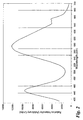
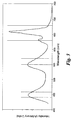
- Figures 2 and 3 show emission spectra of phosphor blends consisting of (Sr 0.79 Eu 0.1 Mn 0.1 Mg 0.11 ) 2 P 2 O 7 , SECA, and MFG; and CASI, SECA, and MFG along with the wavelength ranges of blue, green, and red color filters.
- the phosphor blends were excited by a blue light-emitting LED at a wavelength of about 405 nm.
- the phosphor of a blend of the present invention may be mixed together by any mechanical method including without limitation stirring or blending in a high-speed blender or a ribbon blender.
- the phosphors may be combined and pulverized together in a bowl mill, a hammer mill, or a jet mill. It may be desirable to reduce the phosphor particle size to below 4 micrometers, and preferably below 2 micrometers.
- the phosphor blend can be dispersed in a substantially transparent resin, and a light-conversion sheet is made of the mixture and cured to be disposed between the backlights and the layer of liquid crystal material.
- substantially transparent means allowing at least 80 percent, preferably at least 90 percent, more preferably at least 95 percent, of light in the visible wavelengths to pass through a thickness of about 1 mm.
- suitable resins for the manufacture of a light-conversion sheet includes, but are not limited to, acrylate resins, epoxy resins, silicone, and silicone-functionalized epoxy.
- the light-conversion sheet may also comprise particles of a scattering material, such as TiO 2 or Al 2 O 3 , having particle size similar to that of the phosphor blend.
- the light-conversion sheet may be made by any suitable method, such as casting, spreading, rolling, spraying on a substrate, etc.
- Figure 4 shows perspectively separated components of an LCD 10 using an embodiment of the present invention for backlighting.
- LEDs 20, along with their associated electrical circuit, are disposed on side walls 22 of a tray 25.
- Tray 25 has a reflective bottom surface 24 for upward reflecting electromagnetic radiation emitted by LEDs 20.
- a light-conversion sheet 30 comprising particles of a phosphor blend of the present invention dispersed in a substantially transparent resin is disposed on tray 25.
- the phosphor particles in light-conversion sheet 30 receive and absorb electromagnetic radiation emitted by LEDs 20 and reflected from surface 24 and emit light in the visible wavelengths having intensity concentrated in the blue, green, and read regions.
- a light scattering layer (not shown) may be disposed between tray 25 and light-conversion layer 30.
- the light scattering layer typically has raised features, such as raised dots or corrugated strips, on at least a surface.
- a first light polarizer 40 is disposed on light-conversion layer 30.
- a layer 55 of a liquid crystal material such as a twisted nematic liquid crystal, is contained between two transparent plates 50 and 60. The assembly of layer 55 and plates 50 and 60 is disposed on the first light polarizer 40.
- the surfaces of transparent plates 50 and 60 adjacent to liquid crystal layer 55 carry patterned electrodes that impart a matrix of pixels on the liquid crystal material when a voltage is applied between the electrodes. Blue, green, and red color filters are provided on one transparent plate at the locations of the pixels so as to allow the control of the light color transmitted through each of the pixels.
- a second light polarizer 70 is disposed on the liquid crystal assembly.
- other optional layers such as light diffusers or protective layers, may be included.
- Transparent plates 50 and 60 can comprise glass or transparent plastic plates or films.
- plastic materials are polyethylenterephathalate ("PET"), polyacrylates, polycarbonate, silicone, epoxy resins, silicone-functionalized epoxy resins, polyester, polyimide, polyetherimide, PES, PEN, polynorbonenes, or poly(cyclic olefins).
- PET polyethylenterephathalate
- Such plastic plates or films are advantageously coated on at least one surface thereof with diffusion barrier coatings to prevent unwanted diffusion of reactive chemical species, including without limitation oxygen, water vapor, sulfur-containing compounds, and acid gases, from the environment.
- a diffusion barrier coating can comprise a multilayer coating of alternating layers of at least an inorganic material and at least an organic material.
- the inorganic material of the multilayer diffusion barrier coating is typically selected from the group consisting of metals (the thickness of metallic layers being selected to render the layer substantially transparent), metal carbides, metal oxides, metal nitrides, metal oxycarbides, metal oxynitrides, and carbonitride.
- the inorganic layer may be deposited on the plastic plate or film by physical vapor deposition, chemical vapor deposition, ion-beam assisted deposition, sputtering, or plasma-enhanced chemical vapor deposition.
- the thickness of each inorganic layer is typically in the range from about 1 nm to about 500 nm.
- the organic material of the multilayer diffusion barrier coating is typically selected from the group consisting of polyacrylates such as polymers or copolymers of acrylic acid, methacrylic acid, esters of these acids, or acylonitrile; poly(vinyl fluoride); poly(vinylidene chloride); poly(vinyl alcohol); copolymer of vinyl alcohol and glyoxal; PET, parylene, and polymers derived from cycloolefins and their derivatives such as poly(arylcyclobutene) disclosed in U.S. Patents 4,540,763 and 5,185,391.
- the thickness of the organic layer is typically in the range from about 1 nm to about 10000 nm, preferably from about 10 nm to about 5000 nm.
- the mixture of the substantially transparent resin, phosphor blend, and optionally scattering material is formed into a light-conversion casting that is disposed adjacent to the semiconductor light-emitting element of each of the LEDs to receive light emitted therefrom.
- the light source to provide backlight for an LCD 10 comprises an organic light-emitting device ("OELD") 80.
- OELD 80 typically comprises a layer 85 of an organic electroluminescent (“EL") disposed between two electrodes 83 and 87, which organic EL material is capable of emitting light when a voltage is applied across the electrodes 83 and 87.
- EL organic electroluminescent
- the assembly of electrodes 83 and 87 and organic light-emitting layer 85 may be further disposed or formed on a substantially transparent substrate made of glass or an organic polymer.
- One of the electrodes is made of a substantially transparent conducting oxide, such as indium tin oxide ("ITO"), tin oxide, indium oxide, zinc oxide, indium zinc oxide, cadmium tin oxide, or a mixture thereof, and is disposed between the organic light emitting layer and the liquid crystal layer so that light from the organic light-emitting layer can be transmitted into the liquid crystal layer.
- ITO indium tin oxide
- organic EL materials are polymers, copolymers, mixtures of polymers, and lower molecular-weight organic molecules, all having unsaturated bonds. Such materials possess a delocalized ⁇ -electron system, which gives the polymer chains or organic molecules the ability to support positive and negative charge carriers with high mobility.
- Suitable EL polymers are poly(n-vinylcarbazole) ("PVK", emitting violet-to-blue light in the wavelengths of about 380-500 nm); poly(alkylfluorene) such as poly(9,9-dihexylfluorene) (410-550 nm), poly(dioctylfluorene) (wavelength at peak EL emission of 436 nm), or poly ⁇ 9,9-bis(3,6-dioxaheptyl)-fluorene-2,7-diyl ⁇ (400-550 nm); poly(praraphenylene) derivatives such as poly(2-decyloxy-1,4-phenylene) (400-550 nm). Mixtures of these polymers or copolymers based on one or more of these polymers and others may be used to tune the color of emitted light.
- PVK poly(n-vinylcarbazole)
- PVK poly(n-vin
- polysilanes are linear silicon-backbone polymers substituted with a variety of alkyl and/or aryl side groups. They are quasi one-dimensional materials with delocalized ⁇ -conjugated electrons along polymer backbone chains. Examples of polysilanes are poly(di-n-butylsilane), poly(di-n-pentylsilane), poly(di-n-hexylsilane), poly(methylphenylsilane), and poly ⁇ bis(p-butylphenyl)silane ⁇ which are disclosed in H.
- Organic materials having molecular weight less than about 5000 that are made of a large number of aromatic units are also applicable.
- An example of such materials is 1,3,5-tris ⁇ n-(4-diphenylaminophenyl) phenylamino ⁇ benzene, which emits light in the wavelength range of 380-500 nm.
- the organic EL layer also may be prepared from lower molecular weight organic molecules, such as phenylanthracene, tetraarylethene, coumarin, rubrene, tetraphenylbutadiene, anthracene, perylene, coronene, or their derivatives. These materials generally emit light having maximum wavelength of about 520 nm.
- Still other suitable materials are the low molecular-weight metal organic complexes such as aluminum-, gallium-, and indium-acetylacetonate, which emit light in the wavelength range of 415-457 nm, aluminum-(picolymethylketone)-bis ⁇ 2,6-di(t-butyl)phenoxide ⁇ or scandium-(4-methoxy-picolylmethylketone)-bis(acetylacetonate), which emits in the range of 420-433 nm.
- metal organic complexes such as aluminum-, gallium-, and indium-acetylacetonate, which emit light in the wavelength range of 415-457 nm, aluminum-(picolymethylketone)-bis ⁇ 2,6-di(t-butyl)phenoxide ⁇ or scandium-(4-methoxy-picolylmethylketone)-bis(acetylacetonate), which emits in the range of 420-433 nm.
- a light-conversion sheet as disclosed above, is disposed between the organic light-emitting layer and the liquid crystal layer, to convert light emitted by the organic EL layer to light having substantial intensity in the wavelength ranges of the color filters.
Abstract
Description
- The present invention relates generally to liquid crystal displays ("LCDs") and backlight sources thereof. In particular, the present invention relates to phosphor blends for improved back lighting for color LCDs.
- LCDs are widely used in the electronic industry on products ranging from cellular telephones, calculators, and watches to computers and information displays in automobiles. LCDs have many advantages over competing display technologies in areas such as size, cost, design, flexibility, reliability, and power consumption. These advantages make LCDs a popular choice for designers of electronic devices.
- Liquid crystal material is characterized in that the light transmission through a thin layer of liquid crystal may be altered by applying an electric field to the material. This property is put to use in LCDs.
- The essential component of an LCD consists of a thin liquid crystal material contained between two transparent plates, made of a material such as glass or an organic polymer. The inner surfaces of the transparent plates are provided with transparent electrodes that define the patterns, characters, or images to the displayed. The outer surfaces of the transparent plates are provided with polarizing lenses. When a voltage is applied across a pair of corresponding electrodes, light is blocked or permitted to pass through the assembly, depending on the relative orientation of the polarizing lenses. The location at which two electrodes overlap defines a pixel of the display. Such a display is termed a passive matrix display. In an active matrix display, a matrix of thin-film transistors (TFTs) are disposed on one transparent plate to serve as switching elements. A common electrode is provided on the second transparent plate. When a particular TFT is addressed to switch on, the liquid crystal material between that TFT and the common electrode becomes untwisted and allows light to pass through. A precisely controlled voltage can be supplied to the TFT to control the brightness at the pixel. Red, green, and blue color filters are disposed at adjacent pixels to create a different shade and color from each group of three TFTs when the chosen TFT is activated with a controlled level of voltage.
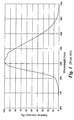
- For display devices having high luminance, a source of backlight is provided behind the transparent plate opposite to the viewer. A miniature fluorescent lamp or a plurality of light-emitting diodes ("LEDs") is typically used for this purpose. Such a light source that emits a broad spectrum, coupled with the color filters, allows for the transmission of a particular light color through the pixel. One white light-emitting backlight system disclosed in U.S. Patent 5,982,092 consists of semiconductor LEDs emitting blue light or ultraviolet ("UV") radiation in the wavelength range of 360-380 nm coupled with a layer of yellow light-emitting Y3Al5O12:Ce phosphor. However, such a system is not energy-efficient because the emission spectrum of Y3Al5O12:Ce is not concentrated in the wavelength ranges specific to the color filters that are typically used (about 440-460 nm, about 550-570 nm, and about 630-680 nm), as is shown in Figure 1.
- Therefore, there is a continued need to provide more energy-efficient backlight systems for LCDs. It is also very desirable to provide phosphor blends for improved color LCDs.
- The present invention provides phosphor compositions for backlight sources in LCDs. Such phosphor compositions offer improved utilization of energy by emitting visible light more intensely in the wavelength ranges of typical blue, green, and red color filters. The terms "light" and "electromagnetic radiation" are used interchangeably herein to mean electromagnetic radiation having wavelengths in the range from about 200 nm to about 770 nm.
- A phosphor composition of the present invention comprises at least a phosphor emitting blue light, at least a phosphor emitting green light, and at least a phosphor emitting red light. The phosphor emitting blue light is selected from the group consisting of (Sr,Ca,Ba,Mg)10(PO4)6(F,Cl,Br,OH):Eu2+ (hereinafter also called "SECA"); (Ba,Sr,Ca)MgAl10O17:Eu2+ (hereinafter also called "BAM"); (Sr,Ca)10(PO4)6·nB2O3:Eu2+, wherein 0 < n < 1; 2SrO·0.84P2O5·0.16B2O3:Eu2+; Sr2Si3O8·2SrCl2:Eu2+; Ba3MgSi2O8:Eu2+; Sr4Al14O25:Eu2+ (hereinafter also called "SAE"); BaAl8O13:Eu2+; and mixtures thereof. The phosphor emitting green light is selected from the group consisting of (Ba,Sr,Ca)MgAl10O17:Eu2+,Mn2+ (hereinafter also called "BAMn"); (Ba,Sr,Ca)Al2O4:Eu2+; (Y,Gd,Lu,Sc,La)BO3:Ce3+,Tb3+; (Ba,Sr,Ca)2SiO4:Eu2+; (Ba,Sr,Ca)2(Mg,Zn)Si2O7:Eu2+; (Sr,Ca,Ba)(Al,Ga,In)2S4:Eu2+; (Y,Gd,Tb,La,Sm,Pr,Lu)x(Al,Ga,In)yO12:Ce3+, wherein x is in the range from about 2.8 to and including 3, and y is in the range from about 4.9 to about 5.1; (Sr,Ca,Ba,Mg,Zn)2P2O7:Eu2+, Mn2+ (hereinafter also called "SPP"); (Ca,Sr,Ba,Mg)10(PO4)6(F,Cl,Br,OH): Eu2+,Mn2+ (hereinafter also called "HALO"); (Ca,Sr,Ba)8(Mg,Zn)(SiO4)4(Cl,F)2:Eu2+,Mn2+ (hereinafter also called "CASI"); and mixtures thereof. The phosphor emitting red light is selected from the group consisting of (Gd,Y,Lu,La)2O3:Eu3+,Bi3+; (Gd,Y,Lu,La)2O2S:Eu3+,Bi3+; (Gd,Y,Lu,La)VO4:Eu3+,Bi3+; SrS:Eu2+; SrY2S4:Eu2+; CaLa2S4:Ce3+; (Ca,Sr)S:Eu2+; 3.5MgO·0.5MgF2·GeO2:Mn4+ (hereinafter also called "MFG"); (Ba,Sr,Ca)MgP2O7:Eu2+,Mn2+; and mixtures thereof.
- In one aspect of the present invention, an LCD comprises a backlight source comprising at least a light source emitting in at least a range from about 300 nm to about 450 nm and a light-conversion phosphor composition comprising at least a phosphor emitting blue light, a phosphor emitting green light, and a phosphor emitting red light. The phosphor composition is disposed to receive electromagnetic radiation emitted by the light source and emits visible light.
- In another aspect of the present invention, the phosphor composition is disposed between the light source and a layer of liquid crystal material of the LCD.
- Other features and advantages of the present invention will be apparent from a perusal of the following detailed description of the invention and the accompanying drawings in which the same numerals refer to like elements.
- The invention will now be described in greater detail, by way of example, with reference to the drawings, in which:-
- Figure 1 is an emission spectrum of the Y3Al5O12:Ce3+ phosphor of the type used in a prior art LCD backlight, as disclosed in U.S. Patent 5,982,092.
- Figure 2 shows an emission spectrum of a phosphor blend consisting of (Sr0.79Eu0.1Mn0.1Mg0.11)2P2O7, SECA, and MFG.
- Figure 3 shows an emission spectrum of a phosphor blend consisting of CASI, SECA, and MFG.
- Figure 4 shows perspectively separated components of an LCD using a backlighting system comprising LEDs and a light-conversion layer of the present invention.
- Figure 5 shows perspectively separated components of an LCD using a backlighting system comprising an organic electroluminescent device and a light-conversion layer of the present invention.
- The present invention provides phosphor compositions for backlight sources in LCDs.
- A phosphor composition of the present invention comprises at least a phosphor emitting blue light, at least a phosphor emitting green light, and at least a phosphor emitting red light. The phosphor emitting blue light is selected from the group consisting of (Sr,Ca,Ba,Mg)10(PO4)6(F,Cl,Br,OH):Eu2+; (Ba,Sr,Ca)MgAl10O17:Eu2+; (Sr,Ca)10(PO4)6·nB2O3:Eu2+, wherein 0 < n < 1; 2SrO·0.84P2O5·0.16B2O3:Eu2+; Sr2Si3O8·2SrCl2:Eu2+; Ba3MgSi2O8:Eu2+; Sr4Al14O25:Eu2+; BaAl8O13:Eu2+; and mixtures thereof. The phosphor emitting green light is selected from the group consisting of (Ba,Sr,Ca)MgAl10O17:Eu2+,Mn2+; (Ba,Sr,Ca)Al2O4:Eu2+; (Y,Gd,Lu,Sc,La)BO3:Ce3+,Tb3+; (Ba,Sr,Ca)2SiO4:Eu2+; (Ba,Sr,Ca)2(Mg,Zn)Si2O7:Eu2+; (Sr,Ca,Ba)(Al,Ga,In)2S4:Eu2+; (Y,Gd,Tb,La,Sm,Pr,Lu)x(Al,Ga,In)yO12:Ce3+, wherein x is in the range from about 2.8 to and including 3, and y is in the range from about 4.9 to about 5.1; (Sr,Ca,Ba,Mg,Zn)2P2O7:Eu2+, Mn2+; (Ca,Sr,Ba,Mg)10(PO4)6(F,Cl,Br,OH): Eu2+,Mn2; (Ca,Sr,Ba)8(Mg,Zn)(SiO4)4(Cl,F)2:Eu2+,Mn2+; and mixtures thereof. The phosphor emitting red light is selected from the group consisting of (Gd,Y,Lu,La)2O3:Eu3+,Bi3+; (Gd,Y,Lu,La)2O2S:Eu3+,Bi3+; (Gd,Y,Lu,La)VO4:Eu3+,Bi3+; SrS:Eu2+; SrY2S4:Eu2+; CaLa2S4:Ce3+; (Ca,Sr)S:Eu2+; 3.5MgO·0.5MgF2·GeO2:Mn4+; (Ba,Sr,Ca)MgP2O7:Eu2+,Mn2+; and mixtures thereof. It is to be understood that the chemical composition of a phosphor disclosed above can vary slightly from the stoichiometric composition indicated, as the phosphor host lattice can accommodate a small amount of lattice defects. Such phosphors are within the scope of the present invention. These phosphors are excitable by electromagnetic radiation in the wavelength range from about 300 nm to about 450 nm and efficiently emit in the blue, green, or red visible region. Therefore, a blend of these selected phosphors are advantageously used in conjunction with at least an LED emitting in the wavelength range from about 300 nm to about 450 nm to provide backlight sources to LCDs.
- In one aspect of the present invention, the phosphors of the blend are selected such that the composite emission spectrum thereof exhibits strong intensity in the wavelength ranges specific to the color filters (e.g., blue, green, and red filters) used in the LCD. For example, many commercial color filter materials are designed to pass through light having wavelengths of 440-460 nm (blue), 550-570 nm (green), and 630-680 nm (red).
- Figures 2 and 3 show emission spectra of phosphor blends consisting of (Sr0.79Eu0.1Mn0.1Mg0.11)2P2O7, SECA, and MFG; and CASI, SECA, and MFG along with the wavelength ranges of blue, green, and red color filters. The phosphor blends were excited by a blue light-emitting LED at a wavelength of about 405 nm.
- The phosphor of a blend of the present invention may be mixed together by any mechanical method including without limitation stirring or blending in a high-speed blender or a ribbon blender. The phosphors may be combined and pulverized together in a bowl mill, a hammer mill, or a jet mill. It may be desirable to reduce the phosphor particle size to below 4 micrometers, and preferably below 2 micrometers.
- The phosphor blend can be dispersed in a substantially transparent resin, and a light-conversion sheet is made of the mixture and cured to be disposed between the backlights and the layer of liquid crystal material. The phrase "substantially transparent" means allowing at least 80 percent, preferably at least 90 percent, more preferably at least 95 percent, of light in the visible wavelengths to pass through a thickness of about 1 mm. Examples of suitable resins for the manufacture of a light-conversion sheet includes, but are not limited to, acrylate resins, epoxy resins, silicone, and silicone-functionalized epoxy. The light-conversion sheet may also comprise particles of a scattering material, such as TiO2 or Al2O3, having particle size similar to that of the phosphor blend. The light-conversion sheet may be made by any suitable method, such as casting, spreading, rolling, spraying on a substrate, etc.
- Figure 4 shows perspectively separated components of an
LCD 10 using an embodiment of the present invention for backlighting.LEDs 20, along with their associated electrical circuit, are disposed onside walls 22 of atray 25.Tray 25 has areflective bottom surface 24 for upward reflecting electromagnetic radiation emitted byLEDs 20. A light-conversion sheet 30 comprising particles of a phosphor blend of the present invention dispersed in a substantially transparent resin is disposed ontray 25. The phosphor particles in light-conversion sheet 30 receive and absorb electromagnetic radiation emitted byLEDs 20 and reflected fromsurface 24 and emit light in the visible wavelengths having intensity concentrated in the blue, green, and read regions. A light scattering layer (not shown) may be disposed betweentray 25 and light-conversion layer 30. The light scattering layer typically has raised features, such as raised dots or corrugated strips, on at least a surface. Afirst light polarizer 40 is disposed on light-conversion layer 30. Alayer 55 of a liquid crystal material, such as a twisted nematic liquid crystal, is contained between twotransparent plates layer 55 andplates first light polarizer 40. The surfaces oftransparent plates liquid crystal layer 55 carry patterned electrodes that impart a matrix of pixels on the liquid crystal material when a voltage is applied between the electrodes. Blue, green, and red color filters are provided on one transparent plate at the locations of the pixels so as to allow the control of the light color transmitted through each of the pixels. A secondlight polarizer 70 is disposed on the liquid crystal assembly. In addition, other optional layers, such as light diffusers or protective layers, may be included. -
Transparent plates - In one embodiment wherein LEDs are used as the light source for backlight, the mixture of the substantially transparent resin, phosphor blend, and optionally scattering material is formed into a light-conversion casting that is disposed adjacent to the semiconductor light-emitting element of each of the LEDs to receive light emitted therefrom.
- In another embodiment of the present invention as shown in Figure 5, the light source to provide backlight for an
LCD 10 comprises an organic light-emitting device ("OELD") 80. Such anOELD 80 typically comprises alayer 85 of an organic electroluminescent ("EL") disposed between twoelectrodes electrodes electrodes layer 85 may be further disposed or formed on a substantially transparent substrate made of glass or an organic polymer. One of the electrodes, typically the anode, is made of a substantially transparent conducting oxide, such as indium tin oxide ("ITO"), tin oxide, indium oxide, zinc oxide, indium zinc oxide, cadmium tin oxide, or a mixture thereof, and is disposed between the organic light emitting layer and the liquid crystal layer so that light from the organic light-emitting layer can be transmitted into the liquid crystal layer. Non-limiting examples of organic EL materials are polymers, copolymers, mixtures of polymers, and lower molecular-weight organic molecules, all having unsaturated bonds. Such materials possess a delocalized π-electron system, which gives the polymer chains or organic molecules the ability to support positive and negative charge carriers with high mobility. Suitable EL polymers are poly(n-vinylcarbazole) ("PVK", emitting violet-to-blue light in the wavelengths of about 380-500 nm); poly(alkylfluorene) such as poly(9,9-dihexylfluorene) (410-550 nm), poly(dioctylfluorene) (wavelength at peak EL emission of 436 nm), or poly{9,9-bis(3,6-dioxaheptyl)-fluorene-2,7-diyl} (400-550 nm); poly(praraphenylene) derivatives such as poly(2-decyloxy-1,4-phenylene) (400-550 nm). Mixtures of these polymers or copolymers based on one or more of these polymers and others may be used to tune the color of emitted light. - Another class of suitable EL polymers is the polysilanes. Polysilanes are linear silicon-backbone polymers substituted with a variety of alkyl and/or aryl side groups. They are quasi one-dimensional materials with delocalized σ-conjugated electrons along polymer backbone chains. Examples of polysilanes are poly(di-n-butylsilane), poly(di-n-pentylsilane), poly(di-n-hexylsilane), poly(methylphenylsilane), and poly{bis(p-butylphenyl)silane} which are disclosed in H. Suzuki et al., "Near-Ultraviolet Electroluminescence From Polysilanes," 331 Thin Solid Films 64-70 (1998). These polysilanes emit light having wavelengths in the range from about 320 nm to about 420 nm.
- Organic materials having molecular weight less than about 5000 that are made of a large number of aromatic units are also applicable. An example of such materials is 1,3,5-tris{n-(4-diphenylaminophenyl) phenylamino}benzene, which emits light in the wavelength range of 380-500 nm. The organic EL layer also may be prepared from lower molecular weight organic molecules, such as phenylanthracene, tetraarylethene, coumarin, rubrene, tetraphenylbutadiene, anthracene, perylene, coronene, or their derivatives. These materials generally emit light having maximum wavelength of about 520 nm. Still other suitable materials are the low molecular-weight metal organic complexes such as aluminum-, gallium-, and indium-acetylacetonate, which emit light in the wavelength range of 415-457 nm, aluminum-(picolymethylketone)-bis{2,6-di(t-butyl)phenoxide} or scandium-(4-methoxy-picolylmethylketone)-bis(acetylacetonate), which emits in the range of 420-433 nm.
- A light-conversion sheet, as disclosed above, is disposed between the organic light-emitting layer and the liquid crystal layer, to convert light emitted by the organic EL layer to light having substantial intensity in the wavelength ranges of the color filters.
- For the sake of good order, various aspects of the invention are set out in the following clauses:-
- 1. A phosphor composition for a backlight source of a liquid crystal display ("LCD"), said phosphor composition comprising at least a phosphor emitting blue light, at least a phosphor emitting green light, and at least a phosphor emitting red light; wherein said at least a phosphor emitting blue light is selected from the group consisting of
(Sr,Ca,Ba,Mg)10(PO4)6(F,Cl,Br,OH):Eu2+; (Ba,Sr,Ca)MgAl10O17:Eu2+;
(Sr,Ca)10(PO4)6·nB2O3:Eu2+, wherein 0 < n < 1;
2SrO·0.84P2O5·0.16B2O3:Eu2+; Sr2Si3O8·2SrCl2:Eu2+; Ba3MgSi2O8:Eu2+;
Sr4Al14O25:Eu2+; BaAl8O13:Eu2+; and mixtures thereof; said at least a phosphor emitting green light is selected from the group consisting of
(Ba,Sr,Ca)MgAl10O17:Eu2+,Mn2+; (Ba,Sr,Ca)Al2O4:Eu2+;
(Y,Gd,Lu,Sc,La)BO3:Ce3+,Tb3+; (Ba,Sr,Ca)2SiO4:Eu2+;
(Ba,Sr,Ca)2(Mg,Zn)Si2O7:Eu2+; (Sr,Ca,Ba)(Al,Ga,In)2S4:Eu2+;
(Y,Gd,Tb,La,Sm,Pr,Lu)x(Al,Ga,In)yO12:Ce3+, wherein x is in the range from about 2.8 to and including 3, and y is in the range from about 4.9 to about 5.1;
(Sr,Ca,Ba,Mg,Zn)2P2O7:Eu2+, Mn2+; (Ca,Sr,Ba,Mg)10(PO4)6(F,Cl,Br,OH):
Eu2+,Mn2+; (Ca,Sr,Ba)8(Mg,Zn)(SiO4)4(Cl,F)2:Eu2+,Mn2+; and mixtures thereof;
and said at least a phosphor emitting red light is selected from the group consisting of (Gd,Y,Lu,La)2O3:Eu3+,Bi3+; (Gd,Y,Lu,La)2O2S:Eu3+,Bi3+;
(Gd,Y,Lu,La)VO4:Eu3+,Bi3+; SrS:Eu2+; SrY2S4:Eu2+; CaLa2S4:Ce3+;
(Ca,Sr)S:Eu2+; 3.5MgO·0.5MgF2·GeO2:Mn4+; (Ba,Sr,Ca)MgP2O7:Eu2+,Mn2+;
and mixtures thereof. - 2. The phosphor composition according to clause 1, wherein said phosphor composition absorbs at least a portion of a first spectrum of light emitted by said backlight source and emits light having a second spectrum different from said first spectrum.
- 3. The phosphor composition according to clause 2, wherein said second spectrum has higher intensity in regions having wavelengths of about 440-460 nm, about 550-570 nm, and about 630-680 nm than in at least another region of visible spectrum.
- 4. The phosphor composition according to clause 1, wherein said phosphor composition comprises (Sr0.79Eu0.1Mn0.1Mg0.11)2P2O7; (Sr,Ca,Ba,Mg)10(PO4)6(F,Cl,Br,OH):Eu2+; and 3.5MgO·0.5MgF2·GeO2:Mn4+.
- 5. The phosphor composition according to clause 1, wherein said phosphor composition comprises (Ca,Sr,Ba)8(Mg,Zn)(SiO4)4(Cl,F)2:Eu2+,Mn2+; (Sr,Ca,Ba,Mg)10(PO4)6(F,Cl,Br,OH):Eu2+; and 3.5MgO·0.5MgF2·GeO2:Mn4+.
- 6. A backlighting system for an LCD comprising:
- a backlight source emitting light having a first spectrum at least in a range from about 300 nm to about 450 nm; and
- a phosphor composition comprising at least a phosphor emitting blue light, at least a phosphor emitting green light, and at least a phosphor emitting red light; wherein said at least a phosphor emitting blue light is selected from the group consisting of (Sr,Ca,Ba,Mg)10(PO4)6(F,Cl,Br,OH):Eu2+;
(Ba,Sr,Ca)MgAl10O17:Eu2+; (Sr,Ca)10(PO4)6·nB2O3:Eu2+, wherein 0 < n < 1;
2SrO·0.84P2O5·0.16B2O3:Eu2+; Sr2Si3O8·2SrCl2:Eu2+; Ba3MgSi2O8:Eu2+;
Sr4Al14O25:Eu2+; BaAl8O13:Eu2+; and mixtures thereof; said at least a phosphor emitting green light is selected from the group consisting of (Ba,Sr,Ca)MgAl10O17:Eu2+,Mn2+; (Ba,Sr,Ca)Al2O4:Eu2+;
(Y,Gd,Lu,Sc,La)BO3:Ce3+,Tb3+; (Ba,Sr,Ca)2SiO4:Eu2+;
(Ba,Sr,Ca)2(Mg,Zn)Si2O7:Eu2+; (Sr,Ca,Ba)(Al,Ga,In)2S4:Eu2+;
(Y,Gd,Tb,La,Sm,Pr,Lu)x(Al,Ga,In)yO12:Ce3+, wherein x is in the range from about 2.8 to and including 3, and y is in the range from about 4.9 to about 5.1; (Sr,Ca,Ba,Mg,Zn)2P2O7:Eu2+, Mn2+; (Ca,Sr,Ba,Mg)10(PO4)6(F,Cl,Br,OH):
Eu2+,Mn2+; (Ca,Sr,Ba)8(Mg,Zn)(SiO4)4(Cl,F)2:Eu2+,Mn2+; and mixtures thereof;
and said at least a phosphor emitting red light is selected from the group consisting of (Gd,Y,Lu,La)2O3:Eu3+;Bi3+; (Gd,Y,Lu,La)2O2S:Eu3+,Bi3+;
(Gd,Y,Lu,La)VO4:Eu3+,Bi3+; SrS:Eu2+; SrY2S4:Eu2+; CaLa2S4:Ce3+;
(Ca,Sr)S:Eu2+; 3.5MgO·0.5MgF2·GeO2:Mn4+; (Ba,Sr,Ca)MgP2O7:Eu2+,Mn2+;
and mixtures thereof;
- 7. The backlighting system according to clause 6, wherein said second spectrum has higher intensity in regions having wavelengths of about 440-460 nm, about 550-570 nm, and about 630-680 nm than in at least another region of visible spectrum.
- 8. The backlighting system according to clause 6, wherein said phosphor composition comprises (Sr0.9Eu0.1Mn0.1Mg0.11)2P2O7;
(Sr,Ca,Ba,Mg)10(PO4)6(F,Cl,Br,OH):Eu2+; and 3.5MgO·0.5MgF2·GeO2:Mn4+. - 9. The backlighting system according to clause 6, wherein said phosphor composition comprises (Ca,Sr,Ba)8(Mg,Zn)(SiO4)4(Cl,F)2:Eu2+,Mn2+; (Sr,Ca,Ba,Mg)10(PO4)6(F,Cl,Br,OH):Eu2+; and 3.5MgO·0.5MgF2·GeO2:Mn4+.
- 10. The backlighting system according to clause 6, wherein said phosphor composition is dispersed in a substantially transparent resin to form a mixture, and said mixture is formed into a light-conversion layer that is disposed between said backlight source and a layer of liquid crystal material of said LCD.
- 11. The backlighting system according to
clause 10, wherein said substantially transparent resin comprises at least a material selected from the group consisting of acrylate resins, epoxy resins, silicone, and silicone-functionalized epoxy. - 12. The backlighting system according to
clause 10, wherein said mixture further comprises particles of a light-scattering material. - 13. The backlighting system according to clause 6, wherein said backlight source comprises at least a light-emitting diode ("LED").
- 14. The backlighting system according to clause 13, wherein said mixture is disposed on a light-emitting element of said LED.
- 15. The backlighting system according to clause 6, wherein said backlight source comprises at least an organic electroluminescent device ("OELD").
- 16. The backlighting system according to clause 15, wherein said OELD comprises an organic light-emitting layer disposed between two electrodes, and said organic light-emitting layer emits light when a voltage is applied across said electrodes.
- 17. A liquid crystal display comprising:
- (a) a backlighting system comprising:
- (1) a backlight source emitting light having a first spectrum at least in a range from about 300 nm to about 450 nm; and
- (2) a phosphor composition comprising at least a phosphor emitting blue light, at least a phosphor emitting green light, and at least a phosphor emitting red light; wherein said at least a phosphor emitting blue light is selected from the group consisting of (Sr,Ca,Ba,Mg)10(PO4)6(F,Cl,Br,OH):Eu2+;
(Ba,Sr,Ca)MgAl10O17:Eu2+; (Sr,Ca)10(PO4)6·nB2O3:Eu2+, wherein 0 < n < 1; 2SrO·0.84P2O5·16B2O3:Eu2+; Sr2Si3O8·2SrCl2:Eu2+; Ba3MgSi2O8:Eu2+;
Sr4Al14O25:Eu2+; BaAl8O13:Eu2+; and mixtures thereof; said at least a phosphor emitting green light is selected from the group consisting of (Ba,Sr,Ca)MgAl10O17:Eu2+,Mn2+; (Ba,Sr,Ca)Al2O4:Eu2+;
(Y,Gd,Lu,Sc,La)BO3:Ce3+,Tb3+; (Ba,Sr,Ca)2SiO4:Eu2+;
(Ba,Sr,Ca)2(Mg,Zn)Si2O7:Eu2+; (Sr,Ca,Ba)(Al,Ga,In)2S4:Eu2+;
(Y,Gd,Tb,La,Sm,Pr,Lu)x(Al,Ga,In)yO12:Ce3+, wherein x is in the range from about 2.8 to and including 3, and y is in the range from about 4.9 to about 5.1; (Sr,Ca,Ba,Mg,Zn)2P2O7:Eu2+, Mn2+; (Ca,Sr,Ba,Mg)10(PO4)6(F,Cl,Br,OH):
Eu2+,Mn2+; (Ca,Sr,Ba)8(Mg,Zn)(SiO4)4(Cl,F)2:Eu2+,Mn2+; and mixtures thereof;
and said at least a phosphor emitting red light is selected from the group consisting of (Gd,Y,Lu,La)2O3:Eu3+,Bi3+; (Gd,Y,Lu,La)2O2S:Eu3+,Bi3+;
(Gd,Y,Lu,La)VO4:Eu3+,Bi3+; SrS:Eu2+; SrY2S4:Eu2+; CaLa2S4:Ce3+;
(Ca,Sr)S:Eu2+; 3.5MgO·0.5MgF2·GeO2:Mn4+; (Ba,Sr,Ca)MgP2O7:Eu2+,Mn2+;
and mixtures thereof;
a liquid crystal material disposed to receive light having said second spectrum. - (a) a backlighting system comprising:
- 18. The liquid crystal display according to clause 17; wherein said liquid crystal material is disposed between a pair of first and second substantially transparent plates, a surface of each of said plates adjacent to said liquid crystal material carries an electrode such that overlapping regions of two electrodes define a plurality of pixels of said liquid crystal display; and color filters allowing blue, green, and red light to pass through said liquid crystal material are disposed on every three adjacent pixels.
- 19. The liquid crystal display according to clause 17, wherein said second spectrum has higher intensity in regions having wavelengths of about 440-460 nm, about 550-570 nm, and about 630-680 nm than in at least another region of visible spectrum.
- 20. The liquid crystal display according to clause 17, wherein said phosphor composition comprises (Sr0.79Eu0.1Mn0.1Mg0.11)2P2O7; (Sr,Ca,Ba,M9)10(PO4)6(F,Cl,Br,OH):EU2+; and 3.5MgO·0.5MgF2.GeO2:Mn4+.
- 21. The liquid crystal display according to clause 17, wherein said phosphor composition comprises (Ca,Sr,Ba)8(Mg,Zn)(SiO4)4(Cl,F)2:Eu2+,Mn2+; (Sr,Ca,Ba,Mg)10(PO4)6(F,Cl,Br,OH):Eu2+; and 3.5MgO·0.5MgF2·GeO2:Mn4+.
- 22. The liquid crystal display according to clause 17, wherein said phosphor composition is dispersed in a substantially transparent resin to form a mixture, and said mixture is formed into a light-conversion layer that is disposed between said backlight source and a layer of liquid crystal material of said LCD.
- 23. The liquid crystal display according to
clause 22, wherein said substantially transparent resin comprises at least a material selected from the group consisting of acrylate resins, epoxy resins, silicone, and silicone-functionalized epoxy. - 24. The liquid crystal display according to
clause 22, wherein said mixture further comprises particles of a light-scattering material. - 25. The liquid crystal display according to clause 17, wherein said backlight source comprises at least an LED.
- 26. The liquid crystal display according to
clause 25, wherein said mixture is disposed on a light-emitting element of said LED. - 27. The liquid crystal display according to clause 17, wherein said backlight source comprises at least an OELD.
- 28. The liquid crystal display according to clause 27, wherein said OELD comprises an organic light-emitting layer disposed between two electrodes, and said organic light-emitting layer emits light when a voltage is applied across said electrodes.
Claims (10)
- A phosphor composition for a backlight source of a liquid crystal display ("LCD"), said phosphor composition comprising at least a phosphor emitting blue light, at least a phosphor emitting green light, and at least a phosphor emitting red light; wherein said at least a phosphor emitting blue light is selected from the group consisting of
(Sr,Ca,Ba,Mg)10(PO4)6(F,Cl,Br,OH):Eu2+; (Ba,Sr,Ca)MgAl10O17:Eu2+;
(Sr,Ca)10(PO4)6·nB2O3:Eu2+, wherein 0 < n < 1;
2SrO·0.84P2O5·0.16B2O3:Eu2+; Sr2Si3O8·2SrCl2:Eu2+; Ba3MgSi2O8:Eu2+;
Sr4Al14O25:Eu2+; BaAl8O13:Eu2+; and mixtures thereof; said at least a phosphor emitting green light is selected from the group consisting of
(Ba,Sr,Ca)MgAl10O17:Eu2+,Mn2+; (Ba,Sr,Ca)Al2O4:Eu2+;
(Y,Gd,Lu,Sc,La)BO3:Ce3+,Tb3+; (Ba,Sr,Ca)2SiO4:Eu2+;
(Ba,Sr,Ca)2(Mg,Zn)Si2O7:Eu2+; (Sr,Ca,Ba)(Al,Ga,In)2S4:Eu2+;
(Y,Gd,Tb,La,Sm,Pr,Lu)x(Al,Ga,In)yO12:Ce3+, wherein x is in the range from about 2.8 to and including 3, and y is in the range from about 4.9 to about 5.1;
(Sr,Ca,Ba,Mg,Zn)2P2O7:Eu2+, Mn2+; (Ca,Sr,Ba,Mg)10(PO4)6(F,Cl,Br,OH):
Eu2+,Mn2+; (Ca,Sr,Ba)8(Mg,Zn)(SiO4)4(Cl,F)2:Eu2+,Mn2+; and mixtures thereof;
and said at least a phosphor emitting red light is selected from the group consisting of (Gd,Y,Lu,La)2O3:Eu3+,Bi3+; (Gd,Y,Lu,La)2O2S:Eu3+,Bi3;
(Gd,Y,Lu,La)VO4:Eu3+,Bi3+; SrS:Eu2+; SrY2S4:Eu2+; CaLa2S4:Ce3+;
(Ca,Sr)S:Eu2+; 3.5MgO·0.5MgF2·GeO2:Mn4+; (Ba,Sr,Ca)MgP2O7:Eu2+,Mn2+;
and mixtures thereof. - The phosphor composition according to claim 1, wherein said phosphor composition absorbs at least a portion of a first spectrum of light emitted by said backlight source and emits light having a second spectrum different from said first spectrum.
- The phosphor composition according to claim 2, wherein said second spectrum has higher intensity in regions having wavelengths of about 440-460 nm, about 550-570 nm, and about 630-680 nm than in at least another region of visible spectrum.
- The phosphor composition according to claim 1, wherein said phosphor composition comprises (Sr0.79Eu0.1Mn0.1Mg0.11)2P2O7; (Sr,Ca,Ba,Mg)10(PO4)6(F,Cl,Br,OH):EU2+ and 3.5MgO.0.5MgF2·GeO2:Mn4+
- A backlighting system for an LCD comprising:a backlight source emitting light having a first spectrum at least in a range from about 300 nm to about 450 nm; anda phosphor composition comprising at least a phosphor emitting blue light, at least a phosphor emitting green light, and at least a phosphor emitting red light; wherein said at least a phosphor emitting blue light is selected from the group consisting of (Sr,Ca,Ba,Mg)10(PO4)6(F,Cl,Br,OH):Eu2+;and mixtures thereof;
(Ba,Sr,Ca)MgAl10O17:Eu2+; (Sr,Ca)10(PO4)6·nB2O3:Eu2+, wherein 0 < n < 1;
2SrO·0.84P2O5·0.16B2O3:Eu2+; Sr2Si3O8·2SrCl2:Eu2+; Ba3MgSi2O8:Eu2+;
Sr4Al14O25:Eu2+, BaAl8O13:Eu2+; and mixtures thereof; said at least a phosphor emitting green light is selected from the group consisting of
(Ba,Sr,Ca)MgAl10O17:EU2+, Mn2+; (Ba,Sr,Ca)Al2O4:Eu2+;
(Y,Gd,Lu,Sc,La)BO3:Ce3+ Tb3+; (Ba,Sr,Ca)2SiO4:Eu2+;
(Ba,Sr,Ca)2(Mg,Zn)Si2O7:Eu2+; (Sr,Ca,Ba)(Al,Ga,In)2S4:Eu2+;
(Y,Gd,Tb,La,Sm,Pr,Lu)x(Al,Ga,In)yO12:Ce3+, wherein x is in the range from about 2.8 to and including 3, and y is in the range from about 4.9 to about 5.1; (Sr,Ca,Ba,Mg,Zn)2P2O7:Eu2+, Mn2+; (Ca,Sr,Ba,Mg)10(PO4)6(F,Cl,Br,OH):
Eu2+,Mn2+; (Ca,Sr,Ba)8(Mg,Zn)(SiO4)4(Cl,F)2:EU2+, Mn2+; and mixtures thereof;
and said at least a phosphor emitting red light is selected from the group consisting of (Gd,Y,Lu,La)2O3:Eu3+,Bi3+; (Gd,Y,Lu,La)2O2S:Eu3+,Bi3+;
(Gd,Y,Lu,La)VO4:Eu3+,Bi3+; SrS:Eu2+; SrY2S4:Eu2+; CaLa2S4:Ce3+;
(Ca,Sr)S:Eu2+; 3.5MgO·0.5MgF2·GeO2:Mn4+; (Ba,Sr,Ca)MgP2O7:Eu2+,Mn2+;
wherein said phosphor composition is disposed to absorb light of at least a portion of said first spectrum and emits light having a second spectrum different from said first spectrum. - The backlighting system according to claim 5, wherein said second spectrum has higher intensity in regions having wavelengths of about 440-460 nm, about 550-570 nm, and about 630-680 nm than in at least another region of visible spectrum.
- The backlighting system according to claim 5, wherein said phosphor composition comprises (Sr0.79Eu0.1Mn0.1Mg0.11)2P2O7;
(Sr,Ca,Ba,Mg)10(PO4)6(F,Cl,Br,OH):Eu2+; and 3.5MgO·0.5MgF2·GeO2:Mn4+. - A liquid crystal display comprising:(a) a backlighting system comprising:and mixtures thereof;(1) a backlight source emitting light having a first spectrum at least in a range from about 300 nm to about 450 nm; and(2) a phosphor composition comprising at least a phosphor emitting blue light, at least a phosphor emitting green light, and at least a phosphor emitting red light; wherein said at least a phosphor emitting blue light is selected from the group consisting of (Sr,Ca,Ba,Mg)10(PO4)6(F,Cl,Br,OH):Eu2+;(Ba,Sr,Ca)MgAl10O17:Eu2+; (Sr,Ca)10(PO4)6·nB2O3:Eu2+, wherein 0 < n < 1;
2SrO·0.84P2O5·0.16B2O3:Eu2+; Sr2Si3O8·2SrCl2:Eu2+; Ba3MgSi2O8:Eu2+;
Sr4Al14O25:Eu2+; BaAl8O13:Eu2+; and mixtures thereof; said at least a phosphor emitting green light is selected from the group consisting of
(Ba,Sr,Ca)MgAl10O17:Eu2+,Mn2+; (Ba,Sr,Ca)Al2O4:Eu2+;
(Y,Gd,Lu,Sc,La)BO3:Ce3+,Tb3+; (Ba,Sr,Ca)2SiO4:Eu2+;
(Ba,Sr,Ca)2(Mg,Zn)Si2O7:Eu2+; (Sr,Ca,Ba)(Al,Ga,In)2S4:Eu2+;
(Y,Gd,Tb,La,Sm,Pr,Lu)x(Al,Ga,In)yO12:Ce3+, wherein x is in the range from about 2.8 to and including 3, and y is in the range from about 4.9 to about 5.1; (Sr,Ca,Ba,Mg,Zn)2P2O7:Eu2+, Mn2+; (Ca,Sr,Ba,Mg)10(PO4)6(F,Cl,Br,OH):
Eu2+,Mn2+; (Ca,Sr,Ba)8(Mg,Zn)(SiO4)4(Cl,F)2:Eu2+,Mn2+; and mixtures thereof;
and said at least a phosphor emitting red light is selected from the group
consisting of (Gd,Y,Lu,La)2O3:Eu3+,Bi3+; (Gd,Y,Lu,La)2O2S:Eu3+,Bi3+;
(Gd,Y,Lu,La)VO4:Eu3+,Bi3+; SrS:Eu2+; SrY2S4:Eu2+; CaLa2S4:Ce3+;
(Ca,Sr)S:Eu2+; 3.5MgO·0.5MgF2·GeO2:Mn4+; (Ba,Sr,Ca)MgP2O7:Eu2+,Mn2+;
wherein said phosphor composition is disposed to absorb light of at least a portion of said first spectrum and emits light having a second spectrum different from said first spectrum; and
a liquid crystal material disposed to receive light having said second spectrum. - The liquid crystal display according to claim 8; wherein said liquid crystal material is disposed between a pair of first and second substantially transparent plates, a surface of each of said plates adjacent to said liquid crystal material carries an electrode such that overlapping regions of two electrodes define a plurality of pixels of said liquid crystal display; and color filters allowing blue, green, and red light to pass through said liquid crystal material are disposed on every three adjacent pixels.
- The liquid crystal display according to claim 8, wherein said second spectrum has higher intensity in regions having wavelengths of about 440-460 nm, about 550-570 nm, and about 630-680 nm than in at least another region of visible spectrum.
Applications Claiming Priority (2)
| Application Number | Priority Date | Filing Date | Title |
|---|---|---|---|
| US10/065,181 US6809781B2 (en) | 2002-09-24 | 2002-09-24 | Phosphor blends and backlight sources for liquid crystal displays |
| US65181 | 2002-09-24 |
Publications (1)
| Publication Number | Publication Date |
|---|---|
| EP1403355A1 true EP1403355A1 (en) | 2004-03-31 |
Family
ID=31975653
Family Applications (1)
| Application Number | Title | Priority Date | Filing Date |
|---|---|---|---|
| EP20030255943 Withdrawn EP1403355A1 (en) | 2002-09-24 | 2003-09-23 | Phosphor blends and blacklight sources for liquid crystal displays |
Country Status (6)
| Country | Link |
|---|---|
| US (1) | US6809781B2 (en) |
| EP (1) | EP1403355A1 (en) |
| JP (1) | JP2004168996A (en) |
| KR (1) | KR100915184B1 (en) |
| CN (1) | CN100426072C (en) |
| TW (1) | TWI282883B (en) |
Cited By (17)
| Publication number | Priority date | Publication date | Assignee | Title |
|---|---|---|---|---|
| WO2006050232A1 (en) * | 2004-11-02 | 2006-05-11 | Gelcore, Llc | Phosphor blends for green traffic signals |
| EP1726631A1 (en) * | 2005-05-23 | 2006-11-29 | SuperNova Optoelectronics Corporation | White light emitting device |
| EP1749871A1 (en) | 2005-07-28 | 2007-02-07 | Sony Corporation | Phosphor, optical device and display device |
| WO2007100824A2 (en) * | 2006-02-28 | 2007-09-07 | Lumination, Llc | Red line emitting phosphors for use in led applications |
| EP1835008A1 (en) * | 2004-08-11 | 2007-09-19 | National Institute for Materials Science | Phosphor, production method thereof and light emitting instrument |
| EP1838806A2 (en) * | 2005-01-14 | 2007-10-03 | Intematix Corporation | Novel aluminate-based green phosphors |
| US7358542B2 (en) | 2005-02-02 | 2008-04-15 | Lumination Llc | Red emitting phosphor materials for use in LED and LCD applications |
| EP1985683A1 (en) * | 2006-02-02 | 2008-10-29 | Mitsubishi Chemical Corporation | Complex oxynitride phosphor, light-emitting device using same, image display, illuminating device, phosphor-containing composition and complex oxynitride |
| EP2078978A3 (en) * | 2004-04-26 | 2009-07-22 | Mitsubishi Chemical Corporation | LCD backlight containing a LED with adapted light emission and suitable colour filters |
| US7648649B2 (en) | 2005-02-02 | 2010-01-19 | Lumination Llc | Red line emitting phosphors for use in led applications |
| US7847309B2 (en) | 2007-07-16 | 2010-12-07 | GE Lighting Solutions, LLC | Red line emitting complex fluoride phosphors activated with Mn4+ |
| US7939996B2 (en) | 2005-11-24 | 2011-05-10 | Koninklijke Philips Electronics N.V. | Display device with solid state fluorescent material |
| US8116181B2 (en) | 2005-11-28 | 2012-02-14 | Koninklijke Philips Electronics N.V. | Apparatus for and method for recording data on a rewritable optical record carrier |
| EP2447768A1 (en) * | 2004-10-19 | 2012-05-02 | Sharp Kabushiki Kaisha | Liquid crystal display device |
| WO2017054898A1 (en) | 2015-09-29 | 2017-04-06 | Merck Patent Gmbh | A photosensitive composition and color converting film |
| WO2018024592A1 (en) | 2016-08-01 | 2018-02-08 | Merck Patent Gmbh | A photosensitive composition, color converting medium, optical devices and method for preparing the thereof |
| WO2019105798A1 (en) | 2017-11-30 | 2019-06-06 | Merck Patent Gmbh | Composition comprising a semiconducting light emitting nanoparticle |
Families Citing this family (177)
| Publication number | Priority date | Publication date | Assignee | Title |
|---|---|---|---|---|
| JP3837488B2 (en) * | 2001-11-30 | 2006-10-25 | 独立行政法人産業技術総合研究所 | Mechanoluminescence material |
| US7452082B2 (en) * | 2004-04-19 | 2008-11-18 | Superimaging, Inc. | Excitation light emission apparatus |
| US7976169B2 (en) * | 2003-05-14 | 2011-07-12 | Sun Innovations, Inc. | Waveguide display |
| US6986581B2 (en) * | 2003-11-03 | 2006-01-17 | Superimaging, Inc. | Light emitting material integrated into a substantially transparent substrate |
| US7090355B2 (en) | 2003-05-19 | 2006-08-15 | Superimaging, Inc. | System and method for a transparent color image display utilizing fluorescence conversion of nano particles and molecules |
| JP4059153B2 (en) * | 2003-06-23 | 2008-03-12 | ソニー株式会社 | Manufacturing method of display device |
| KR100500573B1 (en) * | 2003-07-01 | 2005-07-12 | 삼성전자주식회사 | Metal wiring and method of the same, Image device having metal wiring and method of manufacturing the same |
| TW200510250A (en) * | 2003-09-01 | 2005-03-16 | Showa Denko Kk | Method for producing microparticles of metal oxide |
| US7077979B2 (en) * | 2003-10-10 | 2006-07-18 | The Regents Of The University Of California | Red phosphors for solid state lighting |
| EP1683849A4 (en) * | 2003-10-21 | 2009-04-15 | Sumitomo Chemical Co | Fluorescent material and fluorescent material paste |
| CA2542805A1 (en) * | 2003-11-03 | 2005-05-12 | Super-Imaging, Inc. | Microstructures integrated into a transparent substrate which scatter incident light to display an image |
| US7327078B2 (en) * | 2004-03-30 | 2008-02-05 | Lumination Llc | LED illumination device with layered phosphor pattern |
| US7213923B2 (en) * | 2004-04-19 | 2007-05-08 | Superimaging, Inc. | Emission of visible light in response to absorption of excitation light |
| US20050237462A1 (en) * | 2004-04-26 | 2005-10-27 | Eastman Kodak Company | Alignment layer for liquid crystal display |
| US7724321B2 (en) * | 2004-09-24 | 2010-05-25 | Epistar Corporation | Liquid crystal display |
| US20060066586A1 (en) * | 2004-09-27 | 2006-03-30 | Gally Brian J | Touchscreens for displays |
| WO2006046607A1 (en) * | 2004-10-29 | 2006-05-04 | Fujifilm Corporation | Dispersion type electroluminescence element |
| US20060132043A1 (en) * | 2004-12-20 | 2006-06-22 | Srivastava Alok M | Mercury-free discharge compositions and lamps incorporating gallium |
| WO2006094262A2 (en) * | 2005-03-03 | 2006-09-08 | Superimaging, Inc. | Display |
| KR100799839B1 (en) * | 2005-03-30 | 2008-01-31 | 삼성전기주식회사 | Phosphor blends for converting wavelength and white light emitting device using the same |
| KR20080009198A (en) * | 2005-03-31 | 2008-01-25 | 도와 일렉트로닉스 가부시키가이샤 | Phosphor phosphor sheet, and manufacturing method therefore, and light emission device using the phosphor |
| US7733310B2 (en) | 2005-04-01 | 2010-06-08 | Prysm, Inc. | Display screens having optical fluorescent materials |
| US7474286B2 (en) | 2005-04-01 | 2009-01-06 | Spudnik, Inc. | Laser displays using UV-excitable phosphors emitting visible colored light |
| US7791561B2 (en) | 2005-04-01 | 2010-09-07 | Prysm, Inc. | Display systems having screens with optical fluorescent materials |
| JP4905627B2 (en) * | 2005-04-25 | 2012-03-28 | 株式会社東芝 | Green phosphor, white LED, backlight using the same, and liquid crystal display device |
| US8896004B2 (en) * | 2005-04-26 | 2014-11-25 | Kabushiki Kaisha Toshiba | White LED, backlight using the same, and liquid crystal display device |
| US8089425B2 (en) | 2006-03-03 | 2012-01-03 | Prysm, Inc. | Optical designs for scanning beam display systems using fluorescent screens |
| US7994702B2 (en) | 2005-04-27 | 2011-08-09 | Prysm, Inc. | Scanning beams displays based on light-emitting screens having phosphors |
| KR100780186B1 (en) * | 2005-04-27 | 2007-11-27 | 삼성전기주식회사 | Backlight unit for LCD using light emitting diode |
| US8000005B2 (en) | 2006-03-31 | 2011-08-16 | Prysm, Inc. | Multilayered fluorescent screens for scanning beam display systems |
| TWM279023U (en) * | 2005-04-29 | 2005-10-21 | Super Nova Optoelectronics Cor | White light emitting diode device |
| WO2006126817A1 (en) * | 2005-05-24 | 2006-11-30 | Seoul Semiconductor Co., Ltd. | Green phosphor of thiogallate, red phosphor of alkaline earth sulfide and white light emitting device thereof |
| KR20120109645A (en) * | 2005-06-14 | 2012-10-08 | 덴끼 가가꾸 고교 가부시키가이샤 | Resin composition and sheet containing phosphor, and light emitting element using such composition and sheet |
| DE602006020729D1 (en) * | 2005-07-14 | 2011-04-28 | Philips Intellectual Property | ELECTROLUMINESCENTS LIGHTING SOURCE |
| KR100691273B1 (en) * | 2005-08-23 | 2007-03-12 | 삼성전기주식회사 | Complex Phosphor Powder, Light Emitting Device using the Same and Method for Preparing Complex Phosphor Powder |
| CN1919967A (en) * | 2005-08-26 | 2007-02-28 | 明达光电(厦门)有限公司 | Cocktail fluorescent powder |
| EP2236580A3 (en) * | 2005-09-30 | 2010-11-03 | The Regents of the University of California | Nitride and oxy-nitride cerium based phosphor materials for solid-state lighting applications |
| US20070096646A1 (en) * | 2005-10-28 | 2007-05-03 | Van Nice Harold L | Electroluminescent displays |
| KR101171186B1 (en) * | 2005-11-10 | 2012-08-06 | 삼성전자주식회사 | High luminance light emitting diode and liquid crystal display panel of using the same |
| WO2007080555A1 (en) * | 2006-01-16 | 2007-07-19 | Koninklijke Philips Electronics N.V. | Phosphor converted light emitting device |
| US7884816B2 (en) | 2006-02-15 | 2011-02-08 | Prysm, Inc. | Correcting pyramidal error of polygon scanner in scanning beam display systems |
| US8451195B2 (en) | 2006-02-15 | 2013-05-28 | Prysm, Inc. | Servo-assisted scanning beam display systems using fluorescent screens |
| US7791271B2 (en) | 2006-02-24 | 2010-09-07 | Global Oled Technology Llc | Top-emitting OLED device with light-scattering layer and color-conversion |
| CN100352888C (en) * | 2006-02-27 | 2007-12-05 | 江苏博特新材料有限公司 | Fluorescent powder for white light diode and its production method and usage method |
| CN100386405C (en) * | 2006-02-28 | 2008-05-07 | 华南理工大学 | Red long afterglow luminescent material and its prepn |
| US7682850B2 (en) * | 2006-03-17 | 2010-03-23 | Philips Lumileds Lighting Company, Llc | White LED for backlight with phosphor plates |
| JP5323308B2 (en) * | 2006-09-19 | 2013-10-23 | 株式会社小糸製作所 | Light emitting module |
| GB2442505A (en) * | 2006-10-04 | 2008-04-09 | Sharp Kk | A display with a primary light source for illuminating a nanophosphor re-emission material |
| US8133461B2 (en) | 2006-10-20 | 2012-03-13 | Intematix Corporation | Nano-YAG:Ce phosphor compositions and their methods of preparation |
| US8529791B2 (en) | 2006-10-20 | 2013-09-10 | Intematix Corporation | Green-emitting, garnet-based phosphors in general and backlighting applications |
| JP2008129292A (en) * | 2006-11-20 | 2008-06-05 | Nitto Denko Corp | Color purity improving sheet, optical device, image display device, liquid crystal display device and solar cell |
| CN100575453C (en) * | 2006-11-30 | 2009-12-30 | 中国科学院长春光学精密机械与物理研究所 | A kind of orange light phosphor powder for white light LED and preparation method thereof |
| US8013506B2 (en) | 2006-12-12 | 2011-09-06 | Prysm, Inc. | Organic compounds for adjusting phosphor chromaticity |
| US7959827B2 (en) * | 2007-12-12 | 2011-06-14 | General Electric Company | Persistent phosphor |
| US8333907B2 (en) | 2007-01-17 | 2012-12-18 | Utc Fire & Security Corporation | Articles using persistent phosphors |
| GB2460802B (en) | 2007-03-20 | 2012-09-05 | Prysm Inc | Delivering and displaying advertisment or other application data to display systems |
| US7625502B2 (en) * | 2007-03-26 | 2009-12-01 | General Electric Company | Nano-scale metal halide scintillation materials and methods for making same |
| US7608829B2 (en) * | 2007-03-26 | 2009-10-27 | General Electric Company | Polymeric composite scintillators and method for making same |
| US7708968B2 (en) | 2007-03-26 | 2010-05-04 | General Electric Company | Nano-scale metal oxide, oxyhalide and oxysulfide scintillation materials and methods for making same |
| US7697183B2 (en) | 2007-04-06 | 2010-04-13 | Prysm, Inc. | Post-objective scanning beam systems |
| US8169454B1 (en) | 2007-04-06 | 2012-05-01 | Prysm, Inc. | Patterning a surface using pre-objective and post-objective raster scanning systems |
| CN101950122B (en) | 2007-05-17 | 2012-01-04 | Prysm公司 | Multilayered screens with light-emitting stripes for scanning beam display systems |
| US7857994B2 (en) * | 2007-05-30 | 2010-12-28 | GE Lighting Solutions, LLC | Green emitting phosphors and blends thereof |
| TWI366594B (en) * | 2007-08-10 | 2012-06-21 | Univ Nat Chiao Tung | Phosphors and illuminant use for lighting apparatus |
| US7878657B2 (en) | 2007-06-27 | 2011-02-01 | Prysm, Inc. | Servo feedback control based on invisible scanning servo beam in scanning beam display systems with light-emitting screens |
| US8556430B2 (en) | 2007-06-27 | 2013-10-15 | Prysm, Inc. | Servo feedback control based on designated scanning servo beam in scanning beam display systems with light-emitting screens |
| US8545723B2 (en) * | 2007-12-12 | 2013-10-01 | General Electric Company | Persistent phosphor |
| US20090162667A1 (en) * | 2007-12-20 | 2009-06-25 | Lumination Llc | Lighting device having backlighting, illumination and display applications |
| TWI355412B (en) * | 2007-12-20 | 2012-01-01 | Univ Nat Chiao Tung | Phosphors and lighting apparatus |
| TW200930793A (en) * | 2008-01-10 | 2009-07-16 | Univ Nat Chiao Tung | Phosphors and lighting apparatus |
| EP2242119A4 (en) | 2008-02-07 | 2012-03-07 | Mitsubishi Chem Corp | Semiconductor light emitting device, backlighting device, color image display device and phosphor used for those devices |
| US8740400B2 (en) | 2008-03-07 | 2014-06-03 | Intematix Corporation | White light illumination system with narrow band green phosphor and multiple-wavelength excitation |
| JP4594407B2 (en) * | 2008-03-19 | 2010-12-08 | 国立大学法人 新潟大学 | Phosphor for near-ultraviolet excitation light-emitting element |
| CN102036999A (en) * | 2008-03-21 | 2011-04-27 | 内诺格雷姆公司 | Metal silicon nitride or metal silicon oxynitride submicron phosphor particles and methods for synthesizing these phosphors |
| US8847249B2 (en) | 2008-06-16 | 2014-09-30 | Soraa, Inc. | Solid-state optical device having enhanced indium content in active regions |
| GB2461689A (en) * | 2008-07-07 | 2010-01-13 | Sharp Kk | Illumination panel for display back light |
| US8143148B1 (en) | 2008-07-14 | 2012-03-27 | Soraa, Inc. | Self-aligned multi-dielectric-layer lift off process for laser diode stripes |
| US8767787B1 (en) | 2008-07-14 | 2014-07-01 | Soraa Laser Diode, Inc. | Integrated laser diodes with quality facets on GaN substrates |
| US8805134B1 (en) | 2012-02-17 | 2014-08-12 | Soraa Laser Diode, Inc. | Methods and apparatus for photonic integration in non-polar and semi-polar oriented wave-guided optical devices |
| US7869112B2 (en) | 2008-07-25 | 2011-01-11 | Prysm, Inc. | Beam scanning based on two-dimensional polygon scanner for display and other applications |
| US8124996B2 (en) | 2008-08-04 | 2012-02-28 | Soraa, Inc. | White light devices using non-polar or semipolar gallium containing materials and phosphors |
| US8284810B1 (en) | 2008-08-04 | 2012-10-09 | Soraa, Inc. | Solid state laser device using a selected crystal orientation in non-polar or semi-polar GaN containing materials and methods |
| US8329060B2 (en) * | 2008-10-22 | 2012-12-11 | General Electric Company | Blue-green and green phosphors for lighting applications |
| US8247886B1 (en) | 2009-03-09 | 2012-08-21 | Soraa, Inc. | Polarization direction of optical devices using selected spatial configurations |
| US8422525B1 (en) | 2009-03-28 | 2013-04-16 | Soraa, Inc. | Optical device structure using miscut GaN substrates for laser applications |
| WO2010113771A1 (en) * | 2009-03-30 | 2010-10-07 | 積水化成品工業株式会社 | Light reflector, lighting device, and lighting device for cultivating plant |
| US8299473B1 (en) | 2009-04-07 | 2012-10-30 | Soraa, Inc. | Polarized white light devices using non-polar or semipolar gallium containing materials and transparent phosphors |
| US8837545B2 (en) | 2009-04-13 | 2014-09-16 | Soraa Laser Diode, Inc. | Optical device structure using GaN substrates and growth structures for laser applications |
| US8634442B1 (en) | 2009-04-13 | 2014-01-21 | Soraa Laser Diode, Inc. | Optical device structure using GaN substrates for laser applications |
| DE112010001615T5 (en) | 2009-04-13 | 2012-08-02 | Soraa, Inc. | Structure of an optical element using GaN substrates for laser applications |
| US8791499B1 (en) | 2009-05-27 | 2014-07-29 | Soraa, Inc. | GaN containing optical devices and method with ESD stability |
| US9800017B1 (en) | 2009-05-29 | 2017-10-24 | Soraa Laser Diode, Inc. | Laser device and method for a vehicle |
| US8509275B1 (en) | 2009-05-29 | 2013-08-13 | Soraa, Inc. | Gallium nitride based laser dazzling device and method |
| US9829780B2 (en) | 2009-05-29 | 2017-11-28 | Soraa Laser Diode, Inc. | Laser light source for a vehicle |
| US10108079B2 (en) | 2009-05-29 | 2018-10-23 | Soraa Laser Diode, Inc. | Laser light source for a vehicle |
| US8427590B2 (en) | 2009-05-29 | 2013-04-23 | Soraa, Inc. | Laser based display method and system |
| US8247887B1 (en) | 2009-05-29 | 2012-08-21 | Soraa, Inc. | Method and surface morphology of non-polar gallium nitride containing substrates |
| US9250044B1 (en) | 2009-05-29 | 2016-02-02 | Soraa Laser Diode, Inc. | Gallium and nitrogen containing laser diode dazzling devices and methods of use |
| US9000466B1 (en) | 2010-08-23 | 2015-04-07 | Soraa, Inc. | Methods and devices for light extraction from a group III-nitride volumetric LED using surface and sidewall roughening |
| US8355418B2 (en) | 2009-09-17 | 2013-01-15 | Soraa, Inc. | Growth structures and method for forming laser diodes on {20-21} or off cut gallium and nitrogen containing substrates |
| US8750342B1 (en) | 2011-09-09 | 2014-06-10 | Soraa Laser Diode, Inc. | Laser diodes with scribe structures |
| US8502465B2 (en) | 2009-09-18 | 2013-08-06 | Soraa, Inc. | Power light emitting diode and method with current density operation |
| US8933644B2 (en) | 2009-09-18 | 2015-01-13 | Soraa, Inc. | LED lamps with improved quality of light |
| US9293644B2 (en) | 2009-09-18 | 2016-03-22 | Soraa, Inc. | Power light emitting diode and method with uniform current density operation |
| US9583678B2 (en) | 2009-09-18 | 2017-02-28 | Soraa, Inc. | High-performance LED fabrication |
| US20110186887A1 (en) * | 2009-09-21 | 2011-08-04 | Soraa, Inc. | Reflection Mode Wavelength Conversion Material for Optical Devices Using Non-Polar or Semipolar Gallium Containing Materials |
| US8905588B2 (en) | 2010-02-03 | 2014-12-09 | Sorra, Inc. | System and method for providing color light sources in proximity to predetermined wavelength conversion structures |
| US8740413B1 (en) | 2010-02-03 | 2014-06-03 | Soraa, Inc. | System and method for providing color light sources in proximity to predetermined wavelength conversion structures |
| US20110182056A1 (en) * | 2010-06-23 | 2011-07-28 | Soraa, Inc. | Quantum Dot Wavelength Conversion for Optical Devices Using Nonpolar or Semipolar Gallium Containing Materials |
| US20110215348A1 (en) * | 2010-02-03 | 2011-09-08 | Soraa, Inc. | Reflection Mode Package for Optical Devices Using Gallium and Nitrogen Containing Materials |
| US10147850B1 (en) | 2010-02-03 | 2018-12-04 | Soraa, Inc. | System and method for providing color light sources in proximity to predetermined wavelength conversion structures |
| TWI456027B (en) * | 2010-03-03 | 2014-10-11 | Hitachi Ltd | Closed material sheet with wavelength conversion material and solar cell using the same |
| US9927611B2 (en) | 2010-03-29 | 2018-03-27 | Soraa Laser Diode, Inc. | Wearable laser based display method and system |
| US8451876B1 (en) | 2010-05-17 | 2013-05-28 | Soraa, Inc. | Method and system for providing bidirectional light sources with broad spectrum |
| US9450143B2 (en) | 2010-06-18 | 2016-09-20 | Soraa, Inc. | Gallium and nitrogen containing triangular or diamond-shaped configuration for optical devices |
| US8293551B2 (en) | 2010-06-18 | 2012-10-23 | Soraa, Inc. | Gallium and nitrogen containing triangular or diamond-shaped configuration for optical devices |
| US8816319B1 (en) | 2010-11-05 | 2014-08-26 | Soraa Laser Diode, Inc. | Method of strain engineering and related optical device using a gallium and nitrogen containing active region |
| US9048170B2 (en) | 2010-11-09 | 2015-06-02 | Soraa Laser Diode, Inc. | Method of fabricating optical devices using laser treatment |
| JP5677463B2 (en) * | 2010-11-30 | 2015-02-25 | パナソニック株式会社 | Phosphor and light emitting device |
| KR20140043055A (en) * | 2011-01-14 | 2014-04-08 | 라이트스케이프 머티어리얼스, 인코포레이티드 | Carbonitride and carbidonitride phosphors and lighting devices using the same |
| US9025635B2 (en) | 2011-01-24 | 2015-05-05 | Soraa Laser Diode, Inc. | Laser package having multiple emitters configured on a support member |
| US9595813B2 (en) | 2011-01-24 | 2017-03-14 | Soraa Laser Diode, Inc. | Laser package having multiple emitters configured on a substrate member |
| US8786053B2 (en) | 2011-01-24 | 2014-07-22 | Soraa, Inc. | Gallium-nitride-on-handle substrate materials and devices and method of manufacture |
| US9318875B1 (en) | 2011-01-24 | 2016-04-19 | Soraa Laser Diode, Inc. | Color converting element for laser diode |
| US9093820B1 (en) | 2011-01-25 | 2015-07-28 | Soraa Laser Diode, Inc. | Method and structure for laser devices using optical blocking regions |
| US8780295B2 (en) * | 2011-03-28 | 2014-07-15 | Tsmc Solid State Lighting Ltd. | Light cavity that improves light output uniformity |
| US9287684B2 (en) | 2011-04-04 | 2016-03-15 | Soraa Laser Diode, Inc. | Laser package having multiple emitters with color wheel |
| US8686431B2 (en) | 2011-08-22 | 2014-04-01 | Soraa, Inc. | Gallium and nitrogen containing trilateral configuration for optical devices |
| US9082349B2 (en) * | 2011-08-30 | 2015-07-14 | Sharp Laboratories Of America, Inc. | Multi-primary display with active backlight |
| US8971370B1 (en) | 2011-10-13 | 2015-03-03 | Soraa Laser Diode, Inc. | Laser devices using a semipolar plane |
| US8912025B2 (en) | 2011-11-23 | 2014-12-16 | Soraa, Inc. | Method for manufacture of bright GaN LEDs using a selective removal process |
| EP2823515A4 (en) | 2012-03-06 | 2015-08-19 | Soraa Inc | Light emitting diodes with low refractive index material layers to reduce light guiding effects |
| US9068717B2 (en) * | 2012-03-12 | 2015-06-30 | L-3 Communications Corporation | Backlight display using photoluminescent material tuned to improve NVIS compatibility |
| US9581311B2 (en) * | 2012-03-12 | 2017-02-28 | L-3 Communications Corporation | Backlight display using photoluminescent material tuned to improve NVIS compatibility |
| US9020003B1 (en) | 2012-03-14 | 2015-04-28 | Soraa Laser Diode, Inc. | Group III-nitride laser diode grown on a semi-polar orientation of gallium and nitrogen containing substrates |
| US9343871B1 (en) | 2012-04-05 | 2016-05-17 | Soraa Laser Diode, Inc. | Facet on a gallium and nitrogen containing laser diode |
| US10559939B1 (en) | 2012-04-05 | 2020-02-11 | Soraa Laser Diode, Inc. | Facet on a gallium and nitrogen containing laser diode |
| US9800016B1 (en) | 2012-04-05 | 2017-10-24 | Soraa Laser Diode, Inc. | Facet on a gallium and nitrogen containing laser diode |
| JPWO2013176195A1 (en) * | 2012-05-22 | 2016-01-14 | 宇部マテリアルズ株式会社 | Phosphor mixture with optimized light emission intensity and color rendering in the visible region |
| US8971368B1 (en) | 2012-08-16 | 2015-03-03 | Soraa Laser Diode, Inc. | Laser devices having a gallium and nitrogen containing semipolar surface orientation |
| US9978904B2 (en) | 2012-10-16 | 2018-05-22 | Soraa, Inc. | Indium gallium nitride light emitting devices |
| US8802471B1 (en) | 2012-12-21 | 2014-08-12 | Soraa, Inc. | Contacts for an n-type gallium and nitrogen substrate for optical devices |
| US9166372B1 (en) | 2013-06-28 | 2015-10-20 | Soraa Laser Diode, Inc. | Gallium nitride containing laser device configured on a patterned substrate |
| US8994033B2 (en) | 2013-07-09 | 2015-03-31 | Soraa, Inc. | Contacts for an n-type gallium and nitrogen substrate for optical devices |
| US9520695B2 (en) | 2013-10-18 | 2016-12-13 | Soraa Laser Diode, Inc. | Gallium and nitrogen containing laser device having confinement region |
| US9379525B2 (en) | 2014-02-10 | 2016-06-28 | Soraa Laser Diode, Inc. | Manufacturable laser diode |
| US9368939B2 (en) | 2013-10-18 | 2016-06-14 | Soraa Laser Diode, Inc. | Manufacturable laser diode formed on C-plane gallium and nitrogen material |
| US9362715B2 (en) | 2014-02-10 | 2016-06-07 | Soraa Laser Diode, Inc | Method for manufacturing gallium and nitrogen bearing laser devices with improved usage of substrate material |
| US9419189B1 (en) | 2013-11-04 | 2016-08-16 | Soraa, Inc. | Small LED source with high brightness and high efficiency |
| US9209596B1 (en) | 2014-02-07 | 2015-12-08 | Soraa Laser Diode, Inc. | Manufacturing a laser diode device from a plurality of gallium and nitrogen containing substrates |
| US9871350B2 (en) | 2014-02-10 | 2018-01-16 | Soraa Laser Diode, Inc. | Manufacturable RGB laser diode source |
| US9520697B2 (en) | 2014-02-10 | 2016-12-13 | Soraa Laser Diode, Inc. | Manufacturable multi-emitter laser diode |
| US9564736B1 (en) * | 2014-06-26 | 2017-02-07 | Soraa Laser Diode, Inc. | Epitaxial growth of p-type cladding regions using nitrogen gas for a gallium and nitrogen containing laser diode |
| JP6295237B2 (en) * | 2014-09-30 | 2018-03-14 | 富士フイルム株式会社 | Backlight unit, liquid crystal display device, and wavelength conversion member |
| US9246311B1 (en) | 2014-11-06 | 2016-01-26 | Soraa Laser Diode, Inc. | Method of manufacture for an ultraviolet laser diode |
| US9653642B1 (en) | 2014-12-23 | 2017-05-16 | Soraa Laser Diode, Inc. | Manufacturable RGB display based on thin film gallium and nitrogen containing light emitting diodes |
| US9666677B1 (en) | 2014-12-23 | 2017-05-30 | Soraa Laser Diode, Inc. | Manufacturable thin film gallium and nitrogen containing devices |
| US11437775B2 (en) | 2015-08-19 | 2022-09-06 | Kyocera Sld Laser, Inc. | Integrated light source using a laser diode |
| US10879673B2 (en) | 2015-08-19 | 2020-12-29 | Soraa Laser Diode, Inc. | Integrated white light source using a laser diode and a phosphor in a surface mount device package |
| US11437774B2 (en) | 2015-08-19 | 2022-09-06 | Kyocera Sld Laser, Inc. | High-luminous flux laser-based white light source |
| US10938182B2 (en) | 2015-08-19 | 2021-03-02 | Soraa Laser Diode, Inc. | Specialized integrated light source using a laser diode |
| US9787963B2 (en) | 2015-10-08 | 2017-10-10 | Soraa Laser Diode, Inc. | Laser lighting having selective resolution |
| JP6772621B2 (en) * | 2016-07-27 | 2020-10-21 | 日亜化学工業株式会社 | Light emitting device |
| CN108300473A (en) * | 2016-08-10 | 2018-07-20 | 深圳市光峰光电技术有限公司 | A kind of Wavelength converter and preparation method thereof, light-emitting device and projection arrangement |
| CN106433635B (en) * | 2016-09-26 | 2018-07-27 | 中国科学院长春应用化学研究所 | A kind of long after glow luminous material and preparation method thereof |
| KR20180049462A (en) * | 2016-11-02 | 2018-05-11 | 삼성디스플레이 주식회사 | Display device |
| US10771155B2 (en) | 2017-09-28 | 2020-09-08 | Soraa Laser Diode, Inc. | Intelligent visible light with a gallium and nitrogen containing laser source |
| US10222474B1 (en) | 2017-12-13 | 2019-03-05 | Soraa Laser Diode, Inc. | Lidar systems including a gallium and nitrogen containing laser light source |
| US10551728B1 (en) | 2018-04-10 | 2020-02-04 | Soraa Laser Diode, Inc. | Structured phosphors for dynamic lighting |
| US11421843B2 (en) | 2018-12-21 | 2022-08-23 | Kyocera Sld Laser, Inc. | Fiber-delivered laser-induced dynamic light system |
| US11239637B2 (en) | 2018-12-21 | 2022-02-01 | Kyocera Sld Laser, Inc. | Fiber delivered laser induced white light system |
| US11884202B2 (en) | 2019-01-18 | 2024-01-30 | Kyocera Sld Laser, Inc. | Laser-based fiber-coupled white light system |
| US10903623B2 (en) | 2019-05-14 | 2021-01-26 | Soraa Laser Diode, Inc. | Method and structure for manufacturable large area gallium and nitrogen containing substrate |
| US11228158B2 (en) | 2019-05-14 | 2022-01-18 | Kyocera Sld Laser, Inc. | Manufacturable laser diodes on a large area gallium and nitrogen containing substrate |
| CN110161600B (en) * | 2019-07-09 | 2022-08-30 | 京东方科技集团股份有限公司 | Array substrate, preparation method thereof and liquid crystal display device |
| WO2022163604A1 (en) * | 2021-01-27 | 2022-08-04 | アダマンド並木精密宝石株式会社 | Light emitter, wristwatch, and method for manufacturing light emitter |
| WO2022252400A1 (en) * | 2021-06-04 | 2022-12-08 | 有研稀土新材料股份有限公司 | Near-infrared light-emitting substance and light-emitting device comprising same |
Citations (5)
| Publication number | Priority date | Publication date | Assignee | Title |
|---|---|---|---|---|
| US5608554A (en) * | 1994-07-26 | 1997-03-04 | Samsung Display Devices Co., Ltd. | LCD having a phosphor layer and a backlight source with a main emitting peak in the region of 380-420nm |
| EP0993022A1 (en) * | 1998-09-29 | 2000-04-12 | Matsushita Electronics Corporation | Fluorescent lamp and luminaire with improved illumination light in a low color temperature region |
| US6084250A (en) * | 1997-03-03 | 2000-07-04 | U.S. Philips Corporation | White light emitting diode |
| US6278135B1 (en) * | 1998-02-06 | 2001-08-21 | General Electric Company | Green-light emitting phosphors and light sources using the same |
| US20020158565A1 (en) * | 2001-04-27 | 2002-10-31 | Setlur Anant Achyut | Phosphor blends for generating white light from near-UV/blue light-emitting devices |
Family Cites Families (22)
| Publication number | Priority date | Publication date | Assignee | Title |
|---|---|---|---|---|
| US4573766A (en) | 1983-12-19 | 1986-03-04 | Cordis Corporation | LED Staggered back lighting panel for LCD module |
| US4540763A (en) | 1984-09-14 | 1985-09-10 | The Dow Chemical Company | Polymers derived from poly(arylcyclobutenes) |
| CA1274613A (en) * | 1986-12-24 | 1990-09-25 | Leendert Vriens | Projection device and associated display device |
| US5000878A (en) | 1989-02-24 | 1991-03-19 | American Optical Corporation | Photochromic articles with thermally stable photocolorability |
| US5185391A (en) | 1991-11-27 | 1993-02-09 | The Dow Chemical Company | Oxidation inhibited arylcyclobutene polymers |
| US5838101A (en) * | 1992-10-28 | 1998-11-17 | Gte Products Corporation | Fluorescent lamp with improved CRI and brightness |
| US5616285A (en) * | 1992-12-31 | 1997-04-01 | Osram Sylvania Inc. | Phosphor and method of making same |
| US6013199A (en) * | 1997-03-04 | 2000-01-11 | Symyx Technologies | Phosphor materials |
| US6224240B1 (en) * | 1996-09-13 | 2001-05-01 | Matsushita Electric Industrial Co., Ltd. | Light source |
| JP3155996B2 (en) | 1995-12-12 | 2001-04-16 | アルプス電気株式会社 | Color liquid crystal display |
| US5926239A (en) * | 1996-08-16 | 1999-07-20 | Si Diamond Technology, Inc. | Backlights for color liquid crystal displays |
| US5815228A (en) | 1996-12-06 | 1998-09-29 | Ericsson Inc. | Lighting for liquid crystal displays |
| EP0985007B2 (en) * | 1997-02-24 | 2010-11-03 | Cabot Corporation | Oxygen-containing phosphor powders, methods for making phosphor powders and devices incorporating same |
| US5965907A (en) | 1997-09-29 | 1999-10-12 | Motorola, Inc. | Full color organic light emitting backlight device for liquid crystal display applications |
| US5982092A (en) | 1997-10-06 | 1999-11-09 | Chen; Hsing | Light Emitting Diode planar light source with blue light or ultraviolet ray-emitting luminescent crystal with optional UV filter |
| US6252254B1 (en) * | 1998-02-06 | 2001-06-26 | General Electric Company | Light emitting device with phosphor composition |
| US6469322B1 (en) * | 1998-02-06 | 2002-10-22 | General Electric Company | Green emitting phosphor for use in UV light emitting diodes |
| GB9820805D0 (en) * | 1998-09-25 | 1998-11-18 | Isis Innovation | Divalent lanthanide metal complexes |
| KR100728520B1 (en) | 1999-08-27 | 2007-06-14 | 도요 잉키 세이조 가부시끼가이샤 | Color filter and color liquid crystal display device |
| US6653765B1 (en) * | 2000-04-17 | 2003-11-25 | General Electric Company | Uniform angular light distribution from LEDs |
| US6621211B1 (en) * | 2000-05-15 | 2003-09-16 | General Electric Company | White light emitting phosphor blends for LED devices |
| US6466135B1 (en) * | 2000-05-15 | 2002-10-15 | General Electric Company | Phosphors for down converting ultraviolet light of LEDs to blue-green light |
-
2002
- 2002-09-24 US US10/065,181 patent/US6809781B2/en not_active Expired - Lifetime
-
2003
- 2003-09-15 TW TW092125345A patent/TWI282883B/en not_active IP Right Cessation
- 2003-09-22 JP JP2003329248A patent/JP2004168996A/en active Pending
- 2003-09-23 EP EP20030255943 patent/EP1403355A1/en not_active Withdrawn
- 2003-09-23 KR KR1020030065794A patent/KR100915184B1/en active IP Right Grant
- 2003-09-24 CN CNB031587720A patent/CN100426072C/en not_active Expired - Lifetime
Patent Citations (5)
| Publication number | Priority date | Publication date | Assignee | Title |
|---|---|---|---|---|
| US5608554A (en) * | 1994-07-26 | 1997-03-04 | Samsung Display Devices Co., Ltd. | LCD having a phosphor layer and a backlight source with a main emitting peak in the region of 380-420nm |
| US6084250A (en) * | 1997-03-03 | 2000-07-04 | U.S. Philips Corporation | White light emitting diode |
| US6278135B1 (en) * | 1998-02-06 | 2001-08-21 | General Electric Company | Green-light emitting phosphors and light sources using the same |
| EP0993022A1 (en) * | 1998-09-29 | 2000-04-12 | Matsushita Electronics Corporation | Fluorescent lamp and luminaire with improved illumination light in a low color temperature region |
| US20020158565A1 (en) * | 2001-04-27 | 2002-10-31 | Setlur Anant Achyut | Phosphor blends for generating white light from near-UV/blue light-emitting devices |
Cited By (28)
| Publication number | Priority date | Publication date | Assignee | Title |
|---|---|---|---|---|
| US7830472B2 (en) | 2004-04-26 | 2010-11-09 | Mitsubishi Chemical Corporation | Blue color composition for color filter, color filter, and color image display device |
| EP2078978A3 (en) * | 2004-04-26 | 2009-07-22 | Mitsubishi Chemical Corporation | LCD backlight containing a LED with adapted light emission and suitable colour filters |
| US8040467B2 (en) | 2004-04-26 | 2011-10-18 | Mitsubishi Chemical Corporation | Blue color composition for color filter, color filter, and color image display device |
| EP1835008A1 (en) * | 2004-08-11 | 2007-09-19 | National Institute for Materials Science | Phosphor, production method thereof and light emitting instrument |
| US8253884B2 (en) | 2004-10-19 | 2012-08-28 | Sharp Kabushiki Kaisha | Liquid crystal display device and electronic device using the same |
| EP2447768A1 (en) * | 2004-10-19 | 2012-05-02 | Sharp Kabushiki Kaisha | Liquid crystal display device |
| WO2006050232A1 (en) * | 2004-11-02 | 2006-05-11 | Gelcore, Llc | Phosphor blends for green traffic signals |
| US7321191B2 (en) | 2004-11-02 | 2008-01-22 | Lumination Llc | Phosphor blends for green traffic signals |
| EP1838806A2 (en) * | 2005-01-14 | 2007-10-03 | Intematix Corporation | Novel aluminate-based green phosphors |
| US7755276B2 (en) | 2005-01-14 | 2010-07-13 | Intematix Corporation | Aluminate-based green phosphors |
| EP1838806A4 (en) * | 2005-01-14 | 2009-10-21 | Intematix Corp | Novel aluminate-based green phosphors |
| US7358542B2 (en) | 2005-02-02 | 2008-04-15 | Lumination Llc | Red emitting phosphor materials for use in LED and LCD applications |
| US7497973B2 (en) | 2005-02-02 | 2009-03-03 | Lumination Llc | Red line emitting phosphor materials for use in LED applications |
| US7648649B2 (en) | 2005-02-02 | 2010-01-19 | Lumination Llc | Red line emitting phosphors for use in led applications |
| EP1726631A1 (en) * | 2005-05-23 | 2006-11-29 | SuperNova Optoelectronics Corporation | White light emitting device |
| US7651631B2 (en) | 2005-07-28 | 2010-01-26 | Sony Corporation | Phosphor, optical device, and display device |
| EP1749871A1 (en) | 2005-07-28 | 2007-02-07 | Sony Corporation | Phosphor, optical device and display device |
| US7939996B2 (en) | 2005-11-24 | 2011-05-10 | Koninklijke Philips Electronics N.V. | Display device with solid state fluorescent material |
| US8116181B2 (en) | 2005-11-28 | 2012-02-14 | Koninklijke Philips Electronics N.V. | Apparatus for and method for recording data on a rewritable optical record carrier |
| EP1985683A1 (en) * | 2006-02-02 | 2008-10-29 | Mitsubishi Chemical Corporation | Complex oxynitride phosphor, light-emitting device using same, image display, illuminating device, phosphor-containing composition and complex oxynitride |
| EP1985683A4 (en) * | 2006-02-02 | 2011-05-11 | Mitsubishi Chem Corp | Complex oxynitride phosphor, light-emitting device using same, image display, illuminating device, phosphor-containing composition and complex oxynitride |
| WO2007100824A3 (en) * | 2006-02-28 | 2007-11-15 | Lumination Llc | Red line emitting phosphors for use in led applications |
| WO2007100824A2 (en) * | 2006-02-28 | 2007-09-07 | Lumination, Llc | Red line emitting phosphors for use in led applications |
| US7847309B2 (en) | 2007-07-16 | 2010-12-07 | GE Lighting Solutions, LLC | Red line emitting complex fluoride phosphors activated with Mn4+ |
| WO2017054898A1 (en) | 2015-09-29 | 2017-04-06 | Merck Patent Gmbh | A photosensitive composition and color converting film |
| WO2018024592A1 (en) | 2016-08-01 | 2018-02-08 | Merck Patent Gmbh | A photosensitive composition, color converting medium, optical devices and method for preparing the thereof |
| WO2019105798A1 (en) | 2017-11-30 | 2019-06-06 | Merck Patent Gmbh | Composition comprising a semiconducting light emitting nanoparticle |
| US11732188B2 (en) | 2017-11-30 | 2023-08-22 | Merck Patent Gmbh | Composition comprising a semiconducting light emitting nanoparticle |
Also Published As
| Publication number | Publication date |
|---|---|
| KR100915184B1 (en) | 2009-09-02 |
| CN100426072C (en) | 2008-10-15 |
| US6809781B2 (en) | 2004-10-26 |
| US20040056990A1 (en) | 2004-03-25 |
| KR20040026628A (en) | 2004-03-31 |
| JP2004168996A (en) | 2004-06-17 |
| CN1495486A (en) | 2004-05-12 |
| TW200420975A (en) | 2004-10-16 |
| TWI282883B (en) | 2007-06-21 |
Similar Documents
| Publication | Publication Date | Title |
|---|---|---|
| US6809781B2 (en) | Phosphor blends and backlight sources for liquid crystal displays | |
| US6891330B2 (en) | Mechanically flexible organic electroluminescent device with directional light emission | |
| US6777724B2 (en) | Light-emitting device with organic layer doped with photoluminescent material | |
| US6903505B2 (en) | Light-emitting device with organic electroluminescent material and photoluminescent materials | |
| US6025894A (en) | Scatter control member for organic electroluminescent light source for passing light with or without scattering depending upon an incident angle | |
| KR101893494B1 (en) | Optical member and display device having the same | |
| CN100501528C (en) | Backlight unit having heat dissipating layer, display device having heat dissipating layer, and method for manufacturing heat dissipating layer | |
| KR101936116B1 (en) | Optical member, display device having the same and method for fabricating the same | |
| EP3312893A1 (en) | Diffusion barrier coatings having graded compositions and devices incoroprating the same | |
| CN1910768A (en) | Semi-inverse semi-permeable display unit with full color OLED back light | |
| JP2007103027A (en) | Organic electroluminescent display device and its manufacturing method | |
| CN106501998A (en) | Backlight, display device and its driving method | |
| CN111183315A (en) | Color liquid crystal display and display backlight | |
| JP3672060B2 (en) | Reflective liquid crystal device | |
| CN1955813A (en) | Light source and backlight module | |
| US10094534B2 (en) | Surface-emitting unit having dimming regions | |
| JP5987407B2 (en) | Organic electroluminescence panel | |
| US20090184622A1 (en) | Lamp and display device having the same | |
| KR20130023979A (en) | Liquid crystal display device | |
| CN100477326C (en) | Double-face display organic electroluminescent display device | |
| CN1671256A (en) | Organic electroluminescent display element | |
| JPH11307241A (en) | Organic el power source device | |
| KR20070080997A (en) | Liquid crystal display device with tape carrier package | |
| Okamoto | Inorganic EL Backlights |
Legal Events
| Date | Code | Title | Description |
|---|---|---|---|
| PUAI | Public reference made under article 153(3) epc to a published international application that has entered the european phase |
Free format text: ORIGINAL CODE: 0009012 |
|
| AK | Designated contracting states |
Kind code of ref document: A1 Designated state(s): AT BE BG CH CY CZ DE DK EE ES FI FR GB GR HU IE IT LI LU MC NL PT RO SE SI SK TR |
|
| AX | Request for extension of the european patent |
Extension state: AL LT LV MK |
|
| 17P | Request for examination filed |
Effective date: 20040930 |
|
| 17Q | First examination report despatched |
Effective date: 20041026 |
|
| AKX | Designation fees paid |
Designated state(s): AT BE BG CH CY CZ DE DK EE ES FI FR GB GR HU IE IT LI LU MC NL PT RO SE SI SK TR |
|
| STAA | Information on the status of an ep patent application or granted ep patent |
Free format text: STATUS: THE APPLICATION IS DEEMED TO BE WITHDRAWN |
|
| 18D | Application deemed to be withdrawn |
Effective date: 20081022 |