EP1402918A2 - Catheter for manouvering radioactive source wire to site of treatment - Google Patents
Catheter for manouvering radioactive source wire to site of treatment Download PDFInfo
- Publication number
- EP1402918A2 EP1402918A2 EP20030026317 EP03026317A EP1402918A2 EP 1402918 A2 EP1402918 A2 EP 1402918A2 EP 20030026317 EP20030026317 EP 20030026317 EP 03026317 A EP03026317 A EP 03026317A EP 1402918 A2 EP1402918 A2 EP 1402918A2
- Authority
- EP
- European Patent Office
- Prior art keywords
- catheter
- balloon
- distal end
- plug
- lumen
- Prior art date
- Legal status (The legal status is an assumption and is not a legal conclusion. Google has not performed a legal analysis and makes no representation as to the accuracy of the status listed.)
- Withdrawn
Links
Images


Classifications
-
- A—HUMAN NECESSITIES
- A61—MEDICAL OR VETERINARY SCIENCE; HYGIENE
- A61M—DEVICES FOR INTRODUCING MEDIA INTO, OR ONTO, THE BODY; DEVICES FOR TRANSDUCING BODY MEDIA OR FOR TAKING MEDIA FROM THE BODY; DEVICES FOR PRODUCING OR ENDING SLEEP OR STUPOR
- A61M25/00—Catheters; Hollow probes
- A61M25/10—Balloon catheters
- A61M25/104—Balloon catheters used for angioplasty
-
- A—HUMAN NECESSITIES
- A61—MEDICAL OR VETERINARY SCIENCE; HYGIENE
- A61M—DEVICES FOR INTRODUCING MEDIA INTO, OR ONTO, THE BODY; DEVICES FOR TRANSDUCING BODY MEDIA OR FOR TAKING MEDIA FROM THE BODY; DEVICES FOR PRODUCING OR ENDING SLEEP OR STUPOR
- A61M25/00—Catheters; Hollow probes
- A61M25/10—Balloon catheters
- A61M25/1002—Balloon catheters characterised by balloon shape
-
- A—HUMAN NECESSITIES
- A61—MEDICAL OR VETERINARY SCIENCE; HYGIENE
- A61N—ELECTROTHERAPY; MAGNETOTHERAPY; RADIATION THERAPY; ULTRASOUND THERAPY
- A61N5/00—Radiation therapy
- A61N5/10—X-ray therapy; Gamma-ray therapy; Particle-irradiation therapy
- A61N5/1001—X-ray therapy; Gamma-ray therapy; Particle-irradiation therapy using radiation sources introduced into or applied onto the body; brachytherapy
- A61N5/1002—Intraluminal radiation therapy
-
- A—HUMAN NECESSITIES
- A61—MEDICAL OR VETERINARY SCIENCE; HYGIENE
- A61B—DIAGNOSIS; SURGERY; IDENTIFICATION
- A61B17/00—Surgical instruments, devices or methods, e.g. tourniquets
- A61B17/22—Implements for squeezing-off ulcers or the like on the inside of inner organs of the body; Implements for scraping-out cavities of body organs, e.g. bones; Calculus removers; Calculus smashing apparatus; Apparatus for removing obstructions in blood vessels, not otherwise provided for
- A61B2017/22001—Angioplasty, e.g. PCTA
- A61B2017/22002—Angioplasty, e.g. PCTA preventing restenosis
-
- A—HUMAN NECESSITIES
- A61—MEDICAL OR VETERINARY SCIENCE; HYGIENE
- A61M—DEVICES FOR INTRODUCING MEDIA INTO, OR ONTO, THE BODY; DEVICES FOR TRANSDUCING BODY MEDIA OR FOR TAKING MEDIA FROM THE BODY; DEVICES FOR PRODUCING OR ENDING SLEEP OR STUPOR
- A61M25/00—Catheters; Hollow probes
- A61M25/10—Balloon catheters
- A61M2025/1043—Balloon catheters with special features or adapted for special applications
- A61M2025/1047—Balloon catheters with special features or adapted for special applications having centering means, e.g. balloons having an appropriate shape
-
- A—HUMAN NECESSITIES
- A61—MEDICAL OR VETERINARY SCIENCE; HYGIENE
- A61M—DEVICES FOR INTRODUCING MEDIA INTO, OR ONTO, THE BODY; DEVICES FOR TRANSDUCING BODY MEDIA OR FOR TAKING MEDIA FROM THE BODY; DEVICES FOR PRODUCING OR ENDING SLEEP OR STUPOR
- A61M25/00—Catheters; Hollow probes
- A61M25/10—Balloon catheters
- A61M2025/1043—Balloon catheters with special features or adapted for special applications
- A61M2025/1079—Balloon catheters with special features or adapted for special applications having radio-opaque markers in the region of the balloon
-
- A—HUMAN NECESSITIES
- A61—MEDICAL OR VETERINARY SCIENCE; HYGIENE
- A61M—DEVICES FOR INTRODUCING MEDIA INTO, OR ONTO, THE BODY; DEVICES FOR TRANSDUCING BODY MEDIA OR FOR TAKING MEDIA FROM THE BODY; DEVICES FOR PRODUCING OR ENDING SLEEP OR STUPOR
- A61M25/00—Catheters; Hollow probes
- A61M25/10—Balloon catheters
- A61M2025/1043—Balloon catheters with special features or adapted for special applications
- A61M2025/1086—Balloon catheters with special features or adapted for special applications having a special balloon surface topography, e.g. pores, protuberances, spikes or grooves
-
- A—HUMAN NECESSITIES
- A61—MEDICAL OR VETERINARY SCIENCE; HYGIENE
- A61M—DEVICES FOR INTRODUCING MEDIA INTO, OR ONTO, THE BODY; DEVICES FOR TRANSDUCING BODY MEDIA OR FOR TAKING MEDIA FROM THE BODY; DEVICES FOR PRODUCING OR ENDING SLEEP OR STUPOR
- A61M25/00—Catheters; Hollow probes
- A61M25/10—Balloon catheters
- A61M2025/1043—Balloon catheters with special features or adapted for special applications
- A61M2025/1093—Balloon catheters with special features or adapted for special applications having particular tip characteristics
-
- A—HUMAN NECESSITIES
- A61—MEDICAL OR VETERINARY SCIENCE; HYGIENE
- A61N—ELECTROTHERAPY; MAGNETOTHERAPY; RADIATION THERAPY; ULTRASOUND THERAPY
- A61N5/00—Radiation therapy
- A61N5/10—X-ray therapy; Gamma-ray therapy; Particle-irradiation therapy
- A61N5/1001—X-ray therapy; Gamma-ray therapy; Particle-irradiation therapy using radiation sources introduced into or applied onto the body; brachytherapy
- A61N5/1002—Intraluminal radiation therapy
- A61N2005/1003—Intraluminal radiation therapy having means for centering a radioactive source within the lumen, e.g. balloons
Definitions
- the present invention relates to the field of treating a stenosis which would occur in various blood vessels and other bodily conduits as well as to the field of angioplasty. Additionally, the present invention is directed to the field of treating cancer which would occur in various body conduits or ducts, as well as to the field of brachytherapy.
- a typical angioplasty procedure consists of making a small incision through the body and into a blood vessel and then maneuvering a guide wire through the vascular system to a point beyond the stenosis or occlusion.
- a hollow catheter with a deflatable balloon near its distal end is threaded over the guide wire and advanced to the point of stenosis or occlusion.
- the balloon is then inflated and deflated several times to widen the constricted area, and is then withdrawn from the body.
- the angioplasty procedure does markedly reduce the area of stenosis or occlusion, many patients exhibit a reoccurrence of the stenosis within a few months of the original procedure.
- the Weinstein et al patent describes a method and apparatus for preventing restenosis after angioplasty.
- a balloon catheter transported by a conventional guide wire is delivered to the location of the stenosis.
- Particles or crystals of radioactive material are embedded or mounted on a tube provided inside the balloon catheter.
- a retractable radiation shielding sleeve is slidable along the tube to cover the source of radioactive material.
- the shielding sleeve Upon completion of the angioplasty, the shielding sleeve is retracted and the area of the stenosis is irradiated.
- this apparatus does introduce radiation to the point of the stenosis, the retractable shielding surrounding the source of radioactive material makes this catheter bulky and unwieldy to use.
- a catheter system this bulky would fit into the smaller branches or vessels of the heart. It is also doubtful that a catheter this bulky and stiff could be maneuvered through the tighter bends and turns in many of the vessels.
- An additional embodiment of the Weinstein et al patent illustrates a stent which is made of or coated with a radioactive material such as iridium 192.
- the PCT application illustrates a method and apparatus for restenosis treatment by applying a radioactive dose to the stenosed region after reduction of the region by angioplasty or other means.
- an angioplasty balloon is expanded in the vicinity of a lesion site and radioactive elements provided on the exterior surface of the balloon are forced into contact with the region.
- the present invention is directed to an apparatus for treating the location of a stenosis in a blood vessel or other hollow conduit in which a source of radiation is advanced through the catheter to the site of the stenosis and the site is then treated for a period of time with radiation. Once the treatment is completed, the apparatus is withdrawn.
- Apparatus for treating a stenosis or occlusion in a bodily conduit is characterised, over the features referred to in the preamble of claim 1, by a plug affixed to said distal end of said catheter provided at least partially within the lumen of said catheter and having an interior passageway therethrough, said passageway having a diameter which is greater than the first diameter to allow the guidewire to extend through the plug, but less than the second diameter to prevent the radioactive source wire from passing through the plug beyond the distal end of the catheter.
- Apparatus for treating a stenosis or occlusion in a bodily conduit is characterised, over the features referred to in the preamble of claim 2, by a solid plug affixed within the lumen proximate to said distal end of said catheter and to said portion through which the guidewire is insertable to prevent the radioactive source wire from passing beyond the solid plug into the portion of the catheter through which the guidewire extends and through the distal end of the catheter.
- the apparatus comprises a ribbon balloon on the outside surface of the catheter having a plurality of lobes for centering the catheter within a bodily conduit and for opening an occlusion in a bodily conduit proximate to the distal end thereof, and a source for inflating said ribbon balloon.
- a balloon is provided within the lumen proximate to the distal end of the catheter and a conduit extends along the exterior surface of the catheter from the proximal end thereof to the balloon, a source of inflation being connected to said conduit for inflating the balloon to fill a portion of the catheter to prevent both the guide wire and the radioactive source wire from passing therethrough.
- the catheter is provided with a plurality of openings therein between the proximal and distal ends and a balloon is provided within the lumen, the balloon having a plurality of ribs disposed adjacent to the plurality of openings, a conduit extending along the exterior surface of the catheter from the proximal end to the balloon and, a source of inflation connected to the conduit for inflating the balloon, the arrangement being such that, when the balloon is inflated, the ribs protrude through the openings in the catheter and thereby centre the catheter within the bodily conduit and seal the lumen in the catheter.
- the present invention can be used to treat blockages in many body conduits, for ease of explanation, the present invention will be discussed with respect to a stenosis provided in a blood vessel.
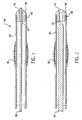
- Figures 1 to 7 illustrate embodiments of the present invention in which the radiation treatment source wire is prevented from being left behind in the body upon removal of the catheter therefrom. Even in situations in which the radioactive source wire breaks, the source wire will not remain inside the body. As shown in Figures 1 and 2, this is accomplished by utilizing a rounded constriction plug having the same outside or slightly larger diameter as the end of a catheter 84.
- the plug 88 is attached to the distal end of the catheter 84 by a multitude of techniques. For example, as shown in Figures 1 to 6, the constriction plug 88 can be crimped over the outside of the catheter 84 or locked in place with internal barbs on the inside of the catheter 84 as shown by 90.
- constriction plug be rounded to allow the catheter system to be advanced more easily and with less trauma within various bodily conduits as it is manoeuvred into position. Without this rounded plug or end, the catheter's edge or end would nick the vessel wall as it is advanced, resulting in unnecessary trauma.
- the catheter system 80 is advanced to the correct position by first inserting a guide wire 86 into the catheter, with the catheter then being manoeuvred to its correct location for treatment. Once the catheter system 80 is correctly positioned, the guide wire 86 is removed and a radioactive treatment source wire 94 is inserted and manoeuvred through the catheter system until it is properly positioned. Therefore, to prevent the radioactive source wire 94 from exiting through the constriction plug 88, while allowing the guide wire 86 to move freely therein, the diameter of an internal passageway 91 of the plug 88 should be less than the diameter of the source wire 94, but greater than the diameter of the guide wire 86.
- the internal passageway 91 of the constriction plug is tapered at 92 to allow the guide wire to easily be inserted into and withdrawn from the constriction plug 88 and the catheter 84.
- An inflatable, ribbed balloon 82 may be attached to the outside surface of the catheter 84 which when inflated properly centres the catheter when it has been manoeuvred into its correct position. When the ribs are inflated by injecting air into a conduit extending along an exterior surface of the catheter to the balloon 82, the size of the stenosis is reduced as well as allowing the catheter to be properly centred.
- Figures 1 and 2 illustrate an open channel catheter system 80, which would require that the radioactive source wire 94 be sterilized before insertion, or germs would enter the body.
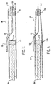
- Figures 3, 4, 5 and 6 address this sterilization problem by utilizing a closed channel catheter system which would allow the advancement and placement of the treatment catheter without requiring that the radioactive source wire be sterilized.
- a permanently affixed plug 114 is placed within a catheter 96, thereby blocking the movement of both the radioactive source wire 94 as well as a guide wire 98. Since the guide wire 92 cannot advance through the solid plug 114, the guide wire 92 remains outside of the catheter 96 for most of its length.
- a port 100 is provided on the side of the catheter 96 which would allow the guide wire 92 to enter the interior of the catheter between the position of the lug 114 and the constriction plug 88.
- This constriction plug 88 is similar in design to the plug which is used with respect to Figures 1 and 2.
- the plug 114 is affixed within the catheter 96 in a manner similar to that which was described with respect to affixing the constriction plug 88 to the end of the catheter with regard to Figures 1 and 2. Since the existence of the plug 114 would effectively prevent the radioactive source wire 94 from proceeding to the constriction plug 88, it is not crucial that the diameter of the internal passage 91 be greater than the diameter of the guide wire 92, but less than the diameter of the radioactive source wire 94. However, for ease of construction, it would be beneficial that the diameter of the internal passageway 91 be greater than the diameter of the guide wire 92, but less than the diameter of the radioactive source wire 94.
- Figure 4 illustrates a catheter similar to the one which was described with respect to Figure 3.
- the distal end 102 of this catheter is tapered and exhibits a smaller diameter than the main portion 104 of the catheter.
- This construction would allow for easier advancement into more restricted areas.
- the guide wire 106 would be smaller in diameter than the guide wire 98 and would exit the interior of the catheter through a side port 108.
- the constriction plug 112 would be smaller than the size of the constriction plug 88.
- the plug 112 would be affixed to the catheter at 110 in a manner similar to that which has been described previously. It is also noted that guide wires 92, 106 would help anchor the catheter into position during treatment.
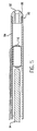
- Figure 5 illustrates a closed catheter system which has already been manoeuvred into place utilizing a guide wire.
- the guide wire Once the guide wire has been used to properly position the catheter, it is removed and an internal balloon 116 is inflated utilizing inflation line 118, thereby completely sealing the inside of the catheter and providing the closed system.
- the balloon should not be deflated until the catheter exits the body, thereby insuring that no germs will enter the body.
- a constriction plug 88 similar to the plug described with respect to Figures 1 to 3, is attached to the distal end of the catheter.
- Figures 6 and 7 illustrate an open catheter system after a guide wire has properly manoeuvred the catheter into place. Similar to the description with respect to Figures 1 and 2, the diameter of the internal passageway 91 of the constriction plug 88 is less than the diameter of the radioactive source wire 94, but greater than the diameter of the guide wire.
- the catheter 84 is provided with radiopaque markings 122 in the vicinity of an external device on the catheter that centers the catheter inside the body.
- This external device takes the form of a plurality of strategically placed bumps or feelers 120 on the external surface of the catheter 84.
- These external devices are constructed from a very soft material, such as teflon, silicon, polyethylene glycol, etc. This material is not likely to induce trauma to a bodily conduit as the catheter is advanced into position. Since these bumps are placed on only several portions of the exterior of the catheter, it would allow bodily fluids to pass as illustrated in Figure 7.
- Figure 8 illustrates a closed catheter system similar to Figure 5.
- the guide wire Once the guide wire has been used to properly position the catheter, it is removed and an internal balloon 116 is inflated utilizing inflation line 118, thereby completely sealing the inside of the catheter 84 allowing the balloon 116 to expand through these ports 132 to help center the catheter inside the bodily conduit.
- a hollow, flexible stent 130 is permanently attached to the balloon 116 to allow partial passage of the treatment wire 94.
- This hollow, flexible stent 130 is permanently attached to the balloon 116 to allow partial passage of the treatment wire 94.
- This hollow, flexible stent 130 is hinged 133 at the opposite end inside the balloon 116.
- This hinge 133 allows the balloon 116 and stent 130 to lay flat when not inflated, so passage of a guide wire through the catheter 84 is possible.
- This hinged section 133 forms a closed end when the balloon 116 is inflated to prevent passage of the treatment wire 94.
- a constriction plug 88 similar to the plug described with respect to Figures 1 to 3 and 5 is attached to the distal end of the catheter.
- Figure 9 illustrates an end view of Figure 8.
- the catheter 84 is centered inside the bodily conduit 124 by means of the balloon 116 exiting through the side portion openings 132 of catheter 84.
- both the constriction plug and the solid plug can be radiopaque.
Abstract
Description
- The present invention relates to the field of treating a stenosis which would occur in various blood vessels and other bodily conduits as well as to the field of angioplasty. Additionally, the present invention is directed to the field of treating cancer which would occur in various body conduits or ducts, as well as to the field of brachytherapy.
- Various techniques have been developed to treat many different conduits in the body when these conduits have become reduced in size due to the existence of a stenosis or have been completely occluded. These techniques include introducing a deflated balloon catheter to the site of the stenosis or occlusion, inflating the balloon one or more times to eliminate the size of the stenosis, deflating the balloon and then removing the balloon catheter from the treatment site.
With respect to the vascular pathways, angioplasty is used to open an artery or blood vessel in the region where the stenosis or the occlusion has occurred. A typical angioplasty procedure consists of making a small incision through the body and into a blood vessel and then maneuvering a guide wire through the vascular system to a point beyond the stenosis or occlusion. A hollow catheter with a deflatable balloon near its distal end is threaded over the guide wire and advanced to the point of stenosis or occlusion. The balloon is then inflated and deflated several times to widen the constricted area, and is then withdrawn from the body.
Unfortunately, although the angioplasty procedure does markedly reduce the area of stenosis or occlusion, many patients exhibit a reoccurrence of the stenosis within a few months of the original procedure.
Although the original stenosis occurs by means of the build up of plaque over a relatively long period of time, experimentation has lead many to believe that the reoccurrence of the stenosis after the original angioplasty procedure is unrelated to the cause of the original stenosis. It is believed that the inflation of the balloon catheter used in the angioplasty procedure or the placement of a stent in the area of the stenosis causes irritation to the blood vessel. This irritation produces a mechanism of action called hyperplasia, inducing the inner layer of the blood vessel cells to rapidly reproduce, thereby causing restenosis. It has been proposed that if the blood vessel is irradiated at the point of the stenosis with a radioactive dose, the mechanism that causes hyperplasia would be destroyed without harming the blood vessel itself.
During this procedure, it is important to precisely control the amount of radiation which is directed to the blood vessel wall, since too much radiation could actually induce hyperplasia as well as destroying a portion of the blood vessel, making it possible for an aneurism or rupture to occur. U.S. Patent 5,213,561 issued to Weinstein et al and U.S. Patent 5,199,939 issued to Dake et al, as well as WO 9304735 to Shefer et al, describe various methods and apparatus for introducing radiation to the site of a stenosis to endeavor to prevent restenosis.
The Weinstein et al patent describes a method and apparatus for preventing restenosis after angioplasty. A balloon catheter transported by a conventional guide wire is delivered to the location of the stenosis. Particles or crystals of radioactive material are embedded or mounted on a tube provided inside the balloon catheter. A retractable radiation shielding sleeve is slidable along the tube to cover the source of radioactive material. Upon completion of the angioplasty, the shielding sleeve is retracted and the area of the stenosis is irradiated. Although this apparatus does introduce radiation to the point of the stenosis, the retractable shielding surrounding the source of radioactive material makes this catheter bulky and unwieldy to use. In this regard, it is very doubtful that a catheter system this bulky would fit into the smaller branches or vessels of the heart. It is also doubtful that a catheter this bulky and stiff could be maneuvered through the tighter bends and turns in many of the vessels.
An additional embodiment of the Weinstein et al patent illustrates a stent which is made of or coated with a radioactive material such as iridium 192. Since the radioactive material is provided on the outer surface of the stent, it is very difficult to precisely administer the proper dosage of radiation to prevent hyperplasia without administering a level of radiation which would actually induce hyperplasia or other deleterious effects to the blood vessel.
The PCT application illustrates a method and apparatus for restenosis treatment by applying a radioactive dose to the stenosed region after reduction of the region by angioplasty or other means. As shown in FIG. 4, an angioplasty balloon is expanded in the vicinity of a lesion site and radioactive elements provided on the exterior surface of the balloon are forced into contact with the region. Therefore, similar to the Weinstein et al patent, the presence of the radioactive material on the exterior of the catheter would make it very difficult to apply the precise amount of radiation to the region of interest. Additionally, both the PCT application as well as the patent to Weinstein describe balloon catheters which do not allow the blood within the vessel to flow during inflation of the balloon.
The patent to Dake et al shows a radioactive catheter for preventing restenosis after angioplasty. However, this patent merely indicates that an elongated flexible catheter is transported to the area of the original stenosis after a balloon catheter has been withdrawn, thereby lengthening the time to administer the entire procedure. - It is known from DE 4033088 to provide an apparatus for treating a stenosis or occlusion in a bodily conduit comprising the features referred to in the preamble to claim 1 or claim 2.
- The aforementioned and other deficiencies of the prior art are addressed by the present invention which is directed to an apparatus for treating the location of a stenosis in a blood vessel or other hollow conduit in which a source of radiation is advanced through the catheter to the site of the stenosis and the site is then treated for a period of time with radiation. Once the treatment is completed, the apparatus is withdrawn.
- Apparatus for treating a stenosis or occlusion in a bodily conduit according to a first aspect of the present invention is characterised, over the features referred to in the preamble of claim 1, by a plug affixed to said distal end of said catheter provided at least partially within the lumen of said catheter and having an interior passageway therethrough, said passageway having a diameter which is greater than the first diameter to allow the guidewire to extend through the plug, but less than the second diameter to prevent the radioactive source wire from passing through the plug beyond the distal end of the catheter.
- Apparatus for treating a stenosis or occlusion in a bodily conduit according to a second aspect of the invention is characterised, over the features referred to in the preamble of claim 2, by a solid plug affixed within the lumen proximate to said distal end of said catheter and to said portion through which the guidewire is insertable to prevent the radioactive source wire from passing beyond the solid plug into the portion of the catheter through which the guidewire extends and through the distal end of the catheter.
- In a preferred embodiment according to the first aspect, the apparatus comprises a ribbon balloon on the outside surface of the catheter having a plurality of lobes for centering the catheter within a bodily conduit and for opening an occlusion in a bodily conduit proximate to the distal end thereof, and a source for inflating said ribbon balloon.
- In another preferred embodiment according to the first aspect of the invention, a balloon is provided within the lumen proximate to the distal end of the catheter and a conduit extends along the exterior surface of the catheter from the proximal end thereof to the balloon, a source of inflation being connected to said conduit for inflating the balloon to fill a portion of the catheter to prevent both the guide wire and the radioactive source wire from passing therethrough.
- In an alternative embodiment according to the first aspect of the invention, the catheter is provided with a plurality of openings therein between the proximal and distal ends and a balloon is provided within the lumen, the balloon having a plurality of ribs disposed adjacent to the plurality of openings, a conduit extending along the exterior surface of the catheter from the proximal end to the balloon and, a source of inflation connected to the conduit for inflating the balloon, the arrangement being such that, when the balloon is inflated, the ribs protrude through the openings in the catheter and thereby centre the catheter within the bodily conduit and seal the lumen in the catheter.
- The above and other objects, features and advantages of embodiments of the present invention will become apparent from the following description, given by way of example only, and taken in conjunction with the accompanying drawings, in which:
- Figure 1 is a longitudinal sectional view of an embodiment of the catheter according to the present invention;
- Figure 2 is a longitudinal sectional view of the catheter shown in Figure 1 including a radioactive source wire,
- Figure 3 is a longitudinal sectional view of a second embodiment of the present invention utilizing a permanent plug;
- Figure 4 is a longitudinal sectional view of the embodiment shown in Figure 3 utilizing a tapered end;
- Figure 5 is a longitudinal sectional view of a third embodiment of the present invention utilizing an internal, inflatable sealing device;
- Figure 6 is a longitudinal sectional view of a fourth embodiment of the present invention provided with a non-inflatable centering device;
- Figure 7 is an end view of Figure 6 with the catheter centered inside a bodily conduit;
- Figure 8 is a longitudinal sectional view of another embodiment of Figure 5 using the internal, inflatable sealing device as a centering device also;
- Figure 9 is an end view of Figure 8 with the catheter centered inside a bodily conduit.
- Although the present invention can be used to treat blockages in many body conduits, for ease of explanation, the present invention will be discussed with respect to a stenosis provided in a blood vessel.
- Figures 1 to 7 illustrate embodiments of the present invention in which the radiation treatment source wire is prevented from being left behind in the body upon removal of the catheter therefrom. Even in situations in which the radioactive source wire breaks, the source wire will not remain inside the body. As shown in Figures 1 and 2, this is accomplished by utilizing a rounded constriction plug having the same outside or slightly larger diameter as the end of a
catheter 84. Theplug 88 is attached to the distal end of thecatheter 84 by a multitude of techniques. For example, as shown in Figures 1 to 6, theconstriction plug 88 can be crimped over the outside of thecatheter 84 or locked in place with internal barbs on the inside of thecatheter 84 as shown by 90. Additional methods of attachment, such as by pasting, gluing, welding, soldering, epoxying or the like can also be employed. It is important that the constriction plug be rounded to allow the catheter system to be advanced more easily and with less trauma within various bodily conduits as it is manoeuvred into position. Without this rounded plug or end, the catheter's edge or end would nick the vessel wall as it is advanced, resulting in unnecessary trauma. - The
catheter system 80 is advanced to the correct position by first inserting aguide wire 86 into the catheter, with the catheter then being manoeuvred to its correct location for treatment. Once thecatheter system 80 is correctly positioned, theguide wire 86 is removed and a radioactivetreatment source wire 94 is inserted and manoeuvred through the catheter system until it is properly positioned. Therefore, to prevent theradioactive source wire 94 from exiting through theconstriction plug 88, while allowing theguide wire 86 to move freely therein, the diameter of aninternal passageway 91 of theplug 88 should be less than the diameter of thesource wire 94, but greater than the diameter of theguide wire 86. Theinternal passageway 91 of the constriction plug is tapered at 92 to allow the guide wire to easily be inserted into and withdrawn from theconstriction plug 88 and thecatheter 84. An inflatable, ribbedballoon 82 may be attached to the outside surface of thecatheter 84 which when inflated properly centres the catheter when it has been manoeuvred into its correct position. When the ribs are inflated by injecting air into a conduit extending along an exterior surface of the catheter to theballoon 82, the size of the stenosis is reduced as well as allowing the catheter to be properly centred. - Figures 1 and 2 illustrate an open
channel catheter system 80, which would require that theradioactive source wire 94 be sterilized before insertion, or germs would enter the body. Figures 3, 4, 5 and 6 address this sterilization problem by utilizing a closed channel catheter system which would allow the advancement and placement of the treatment catheter without requiring that the radioactive source wire be sterilized. As shown in Figure 3, a permanently affixedplug 114 is placed within acatheter 96, thereby blocking the movement of both theradioactive source wire 94 as well as a guide wire 98. Since theguide wire 92 cannot advance through thesolid plug 114, theguide wire 92 remains outside of thecatheter 96 for most of its length. Aport 100 is provided on the side of thecatheter 96 which would allow theguide wire 92 to enter the interior of the catheter between the position of thelug 114 and theconstriction plug 88. This constriction plug 88 is similar in design to the plug which is used with respect to Figures 1 and 2. Theplug 114 is affixed within thecatheter 96 in a manner similar to that which was described with respect to affixing theconstriction plug 88 to the end of the catheter with regard to Figures 1 and 2. Since the existence of theplug 114 would effectively prevent theradioactive source wire 94 from proceeding to theconstriction plug 88, it is not crucial that the diameter of theinternal passage 91 be greater than the diameter of theguide wire 92, but less than the diameter of theradioactive source wire 94. However, for ease of construction, it would be beneficial that the diameter of theinternal passageway 91 be greater than the diameter of theguide wire 92, but less than the diameter of theradioactive source wire 94. - Figure 4 illustrates a catheter similar to the one which was described with respect to Figure 3. However, the
distal end 102 of this catheter is tapered and exhibits a smaller diameter than themain portion 104 of the catheter. This construction would allow for easier advancement into more restricted areas. In this situation, theguide wire 106 would be smaller in diameter than the guide wire 98 and would exit the interior of the catheter through aside port 108. Theconstriction plug 112 would be smaller than the size of theconstriction plug 88. However, theplug 112 would be affixed to the catheter at 110 in a manner similar to that which has been described previously. It is also noted thatguide wires - Figure 5 illustrates a closed catheter system which has already been manoeuvred into place utilizing a guide wire. Once the guide wire has been used to properly position the catheter, it is removed and an
internal balloon 116 is inflated utilizinginflation line 118, thereby completely sealing the inside of the catheter and providing the closed system. The balloon should not be deflated until the catheter exits the body, thereby insuring that no germs will enter the body. Aconstriction plug 88, similar to the plug described with respect to Figures 1 to 3, is attached to the distal end of the catheter. - Figures 6 and 7 illustrate an open catheter system after a guide wire has properly manoeuvred the catheter into place. Similar to the description with respect to Figures 1 and 2, the diameter of the
internal passageway 91 of theconstriction plug 88 is less than the diameter of theradioactive source wire 94, but greater than the diameter of the guide wire. Thecatheter 84 is provided withradiopaque markings 122 in the vicinity of an external device on the catheter that centers the catheter inside the body. This external device takes the form of a plurality of strategically placed bumps orfeelers 120 on the external surface of thecatheter 84. These external devices are constructed from a very soft material, such as teflon, silicon, polyethylene glycol, etc. This material is not likely to induce trauma to a bodily conduit as the catheter is advanced into position. Since these bumps are placed on only several portions of the exterior of the catheter, it would allow bodily fluids to pass as illustrated in Figure 7. - Figure 8 illustrates a closed catheter system similar to Figure 5. Once the guide wire has been used to properly position the catheter, it is removed and an
internal balloon 116 is inflated utilizinginflation line 118, thereby completely sealing the inside of thecatheter 84 allowing theballoon 116 to expand through theseports 132 to help center the catheter inside the bodily conduit. A hollow,flexible stent 130 is permanently attached to theballoon 116 to allow partial passage of thetreatment wire 94. This hollow,flexible stent 130 is permanently attached to theballoon 116 to allow partial passage of thetreatment wire 94. This hollow,flexible stent 130 is hinged 133 at the opposite end inside theballoon 116. Thishinge 133 allows theballoon 116 andstent 130 to lay flat when not inflated, so passage of a guide wire through thecatheter 84 is possible. This hingedsection 133 forms a closed end when theballoon 116 is inflated to prevent passage of thetreatment wire 94. Aconstriction plug 88, similar to the plug described with respect to Figures 1 to 3 and 5 is attached to the distal end of the catheter. - Figure 9 illustrates an end view of Figure 8. The
catheter 84 is centered inside thebodily conduit 124 by means of theballoon 116 exiting through theside portion openings 132 ofcatheter 84. - Although preferred forms of the present invention have been herein disclosed, it is to be understood that the present disclosure is made by way of example and that variation of posture without departing from the scope of the hereinafter claimed subject matter. For example, both the constriction plug and the solid plug can be radiopaque.
Claims (14)
- Apparatus for treating a stenosis or occlusion in a bodily conduit comprising a flexible elongate catheter (84) having a proximal and distal end and with a lumen extending therethrough, a flexible elongate guide wire (86) having a first diameter insertable through said lumen so as to extend through the distal end of the catheter and an elongate radioactive source wire (94) having a second diameter insertable into the lumen when the guidewire (86) has been removed therefrom,
characterised by a plug (88,112) affixed to said distal end of said catheter (84) provided at least partially within the lumen of said catheter (84) and having an interior passageway (91) therethrough, said passageway (91) having a diameter which is greater than the first diameter to allow the guidewire (86) to extend through the plug (88,112), but less than the second diameter to prevent the radioactive source wire (94) from passing through the plug (88,1162) beyond the distal end of the catheter (84). - Apparatus according to claim 1 comprising a ribbed balloon (82) on the outside surface of the catheter (84,96,102) having a plurality of lobes for centering the catheter (84,96,102) within a bodily conduit and for opening an occlusion in a bodily conduit proximate to the distal end thereof, and a source (118) for inflating said ribbed balloon (82).
- Apparatus according to claim 1 or claim 2 wherein the diameter of the constriction plug (88) is equal to or slightly larger than the diameter of the lumen extending through the catheter (84,96,102).
- Apparatus according to any preceding claim wherein the distal end of the constriction plug (88) is rounded.
- Apparatus according to any preceding claim wherein the distal end of the constriction plug (88) is rounded.
- Apparatus according to claims 3 to 6 wherein a plurality of nodes (120) are provided on the exterior surface of said distal end of the catheter (84,96,102).
- Apparatus according to any preceding claim wherein a portion of said constriction plug (88) extends beyond the distal end of said catheter (84,96,102).
- Apparatus according to any preceding claim wherein the constriction plug (88) is provided with a plurality of barbs (90) for attachment to the catheter (84,96,102).
- Apparatus according to any preceding claim wherein a balloon (116) is provided within the lumen proximate to the distal end of the catheter (84,96,102) and a conduit (118) extends along the exterior surface of the catheter (84,96,102) from the proximal end thereof to the balloon (116), a source of inflation being connected to said conduit (118) for inflating the balloon (116) to fill a portion of the catheter (84,96,102) to prevent both the guide wire (86) and the radioactive source wire (94) from passing therethrough.
- Apparatus according to claim 9 wherein the balloon (116) seals the lumen to prevent germs and bodily fluids from passing therethrough.
- Apparatus according to any preceding claim wherein the catheter (84,96,102) is provided with a plurality of openings (132) therein between the proximal and distal ends and a balloon (116) is provided within the lumen, the balloon (116) having a plurality of ribs disposed adjacent to the plurality of openings (132), a conduit (118) extending along the exterior surface of the catheter (84,96,102) from the proximal end to the balloon (116) and, a source of inflation connected to the conduit (118) for inflating the balloon (116), the arrangement being such that, when the balloon (116) is inflated, the ribs protrude through the openings (132) in the catheter (84,96,102) and thereby centre the catheter (84,96,102) within the bodily conduit and seal the lumen in the catheter (84,96,102).
- Apparatus according to claim 11 including a hollow, flexible stent (130) provided within the interior of the balloon (116), said stent (130) lying flat when the balloon is deflated.
- Apparatus according to claim 12 wherein the stent (130) includes a hinge (133) forming a closed end when said balloon (116) is inflated to prevent passage of the radioactive source wire (94).
- Apparatus according to any of claims 11 to 13 wherein the constriction plug (88) is fitted to the termination of the distal end of the catheter (84,96,102).
Applications Claiming Priority (3)
| Application Number | Priority Date | Filing Date | Title |
|---|---|---|---|
| US316500 | 1994-09-30 | ||
| US08/316,500 US5618266A (en) | 1994-03-31 | 1994-09-30 | Catheter for maneuvering radioactive source wire to site of treatment |
| EP95933934A EP0783340A4 (en) | 1994-09-30 | 1995-09-29 | Catheter for maneuvering radioactive source wire to site of treatment |
Related Parent Applications (2)
| Application Number | Title | Priority Date | Filing Date |
|---|---|---|---|
| EP95933934A Division EP0783340A4 (en) | 1994-09-30 | 1995-09-29 | Catheter for maneuvering radioactive source wire to site of treatment |
| EP95933934.2 Division | 1996-04-11 |
Publications (2)
| Publication Number | Publication Date |
|---|---|
| EP1402918A2 true EP1402918A2 (en) | 2004-03-31 |
| EP1402918A3 EP1402918A3 (en) | 2005-03-23 |
Family
ID=23229312
Family Applications (2)
| Application Number | Title | Priority Date | Filing Date |
|---|---|---|---|
| EP95933934A Withdrawn EP0783340A4 (en) | 1994-09-30 | 1995-09-29 | Catheter for maneuvering radioactive source wire to site of treatment |
| EP03026317A Withdrawn EP1402918A3 (en) | 1994-09-30 | 1995-09-29 | Catheter for manouvering radioactive source wire to site of treatment |
Family Applications Before (1)
| Application Number | Title | Priority Date | Filing Date |
|---|---|---|---|
| EP95933934A Withdrawn EP0783340A4 (en) | 1994-09-30 | 1995-09-29 | Catheter for maneuvering radioactive source wire to site of treatment |
Country Status (6)
| Country | Link |
|---|---|
| US (1) | US5618266A (en) |
| EP (2) | EP0783340A4 (en) |
| JP (1) | JPH10509332A (en) |
| AU (1) | AU702117B2 (en) |
| CA (1) | CA2199967A1 (en) |
| WO (1) | WO1996010436A1 (en) |
Cited By (1)
| Publication number | Priority date | Publication date | Assignee | Title |
|---|---|---|---|---|
| CN105749415A (en) * | 2016-02-03 | 2016-07-13 | 陈挺松 | Balloon catheter applied to portal vein |
Families Citing this family (158)
| Publication number | Priority date | Publication date | Assignee | Title |
|---|---|---|---|---|
| EP0813894B1 (en) | 1993-07-01 | 2001-12-05 | Schneider (Europe) GmbH | Medical appliances for the treatment of blood vessels by means of ionizing radiation |
| US6196996B1 (en) * | 1993-07-15 | 2001-03-06 | Paul S. Teirstein | Irradiation catheter and method of use |
| US5840064A (en) * | 1994-03-31 | 1998-11-24 | United States Surgical Corporation | Method and apparatus for treating stenosis or other constriction in a bodily conduit |
| ATE170708T1 (en) | 1994-06-10 | 1998-09-15 | Schneider Europ Gmbh | MEDICINAL DEVICE FOR THE TREATMENT OF A PART OF BODY VESSEL USING IONIZATION RADIATION |
| EP0688580B1 (en) | 1994-06-24 | 2000-10-04 | Schneider (Europe) GmbH | Medical appliance for the treatment of a portion of body vessel by ionising radiation |
| US6503185B1 (en) | 1994-10-27 | 2003-01-07 | Novoste Corporation | Method and apparatus for treating a desired area in the vascular system of a patient |
| US5683345A (en) * | 1994-10-27 | 1997-11-04 | Novoste Corporation | Method and apparatus for treating a desired area in the vascular system of a patient |
| US5833593A (en) * | 1995-11-09 | 1998-11-10 | United States Surgical Corporation | Flexible source wire for localized internal irradiation of tissue |
| DE69530302T2 (en) * | 1995-12-05 | 2004-01-29 | Schneider Europ Gmbh Buelach | A filament for irradiating a living body and a method for producing a filament for irradiating a living body |
| NL1002044C2 (en) * | 1996-01-08 | 1997-07-09 | Optische Ind De Oude Delft Nv | Radioactive source that has clinically relevant beta radiation |
| US5882290A (en) * | 1996-02-29 | 1999-03-16 | Scimed Life Systems, Inc. | Intravascular radiation delivery system |
| US6234951B1 (en) | 1996-02-29 | 2001-05-22 | Scimed Life Systems, Inc. | Intravascular radiation delivery system |
| US5951458A (en) * | 1996-02-29 | 1999-09-14 | Scimed Life Systems, Inc. | Local application of oxidizing agents to prevent restenosis |
| US6099454A (en) * | 1996-02-29 | 2000-08-08 | Scimed Life Systems, Inc. | Perfusion balloon and radioactive wire delivery system |
| US5855546A (en) | 1996-02-29 | 1999-01-05 | Sci-Med Life Systems | Perfusion balloon and radioactive wire delivery system |
| JP2000509014A (en) | 1996-03-11 | 2000-07-18 | フォーカル,インコーポレイテッド | Polymer delivery of radionuclides and radiopharmaceuticals |
| IL118669A (en) * | 1996-06-17 | 2000-02-17 | Israel Atomic Energy Comm | Radioactive catheter |
| NL1003529C2 (en) * | 1996-07-05 | 1998-01-07 | Optische Ind Oede Oude Delftoe | Catheter with centering means. |
| NL1003527C2 (en) | 1996-07-05 | 1998-01-07 | Optische Ind Oede Oude Delftoe | Catheter. |
| US5871436A (en) * | 1996-07-19 | 1999-02-16 | Advanced Cardiovascular Systems, Inc. | Radiation therapy method and device |
| US5910101A (en) * | 1996-08-29 | 1999-06-08 | Advanced Cardiovascular Systems, Inc. | Device for loading and centering a vascular radiation therapy source |
| US5782740A (en) * | 1996-08-29 | 1998-07-21 | Advanced Cardiovascular Systems, Inc. | Radiation dose delivery catheter with reinforcing mandrel |
| US5947924A (en) | 1996-09-13 | 1999-09-07 | Angiorad, L.L.C. | Dilatation/centering catheter used for the treatment of stenosis or other constriction in a bodily passageway and method thereof |
| CA2266638C (en) | 1996-09-23 | 2007-05-01 | Novoste Corporation | Intraluminal radiation treatment system |
| US5797948A (en) * | 1996-10-03 | 1998-08-25 | Cordis Corporation | Centering balloon catheter |
| CA2217092C (en) * | 1996-10-03 | 2007-07-10 | Cordis Corporation | Centering balloon catheter |
| US6261320B1 (en) | 1996-11-21 | 2001-07-17 | Radiance Medical Systems, Inc. | Radioactive vascular liner |
| US5873811A (en) * | 1997-01-10 | 1999-02-23 | Sci-Med Life Systems | Composition containing a radioactive component for treatment of vessel wall |
| US5910102A (en) * | 1997-01-10 | 1999-06-08 | Scimed Life Systems, Inc. | Conversion of beta radiation to gamma radiation for intravascular radiation therapy |
| US6491619B1 (en) | 1997-01-31 | 2002-12-10 | Endologix, Inc | Radiation delivery catheters and dosimetry methods |
| US6287249B1 (en) | 1998-02-19 | 2001-09-11 | Radiance Medical Systems, Inc. | Thin film radiation source |
| US5782742A (en) | 1997-01-31 | 1998-07-21 | Cardiovascular Dynamics, Inc. | Radiation delivery balloon |
| US6458069B1 (en) | 1998-02-19 | 2002-10-01 | Endology, Inc. | Multi layer radiation delivery balloon |
| US5772642A (en) * | 1997-02-19 | 1998-06-30 | Medtronic, Inc. | Closed end catheter |
| AT405136B (en) * | 1997-02-27 | 1999-05-25 | Oesterr Forsch Seibersdorf | DEVICE FOR THE INTRAVASCULAR TREATMENT OF RESTENOSES |
| US6059713A (en) * | 1997-03-06 | 2000-05-09 | Scimed Life Systems, Inc. | Catheter system having tubular radiation source with movable guide wire |
| US5865720A (en) * | 1997-03-06 | 1999-02-02 | Scimed Life Systems, Inc. | Expandable and retrievable radiation delivery system |
| US6110097A (en) * | 1997-03-06 | 2000-08-29 | Scimed Life Systems, Inc. | Perfusion balloon catheter with radioactive source |
| US6676590B1 (en) | 1997-03-06 | 2004-01-13 | Scimed Life Systems, Inc. | Catheter system having tubular radiation source |
| US6312374B1 (en) | 1997-03-06 | 2001-11-06 | Progenix, Llc | Radioactive wire placement catheter |
| US6770058B1 (en) | 1997-03-11 | 2004-08-03 | Interventional Therapies, Llc | Treatment catheter insert |
| US6059812A (en) | 1997-03-21 | 2000-05-09 | Schneider (Usa) Inc. | Self-expanding medical device for centering radioactive treatment sources in body vessels |
| US6309339B1 (en) | 1997-03-28 | 2001-10-30 | Endosonics Corporation | Intravascular radiation delivery device |
| US6033357A (en) * | 1997-03-28 | 2000-03-07 | Navius Corporation | Intravascular radiation delivery device |
| US6210312B1 (en) | 1997-05-20 | 2001-04-03 | Advanced Cardiovascular Systems, Inc. | Catheter and guide wire assembly for delivery of a radiation source |
| US6019718A (en) | 1997-05-30 | 2000-02-01 | Scimed Life Systems, Inc. | Apparatus for intravascular radioactive treatment |
| DE19729075A1 (en) * | 1997-07-08 | 1999-01-14 | Eurotope Entwicklungsgesellsch | Radioactive radiation source with broadband radiation intensity and method for its use |
| AT407009B (en) | 1997-09-01 | 2000-11-27 | Ali Dr Hassan | CATHETER DEVICE FOR RADIOACTIVE TREATMENT OF BODY CAVES |
| JP2001515773A (en) | 1997-09-11 | 2001-09-25 | クック インコーポレイティド | Medical radiotherapy drug injection device |
| US6491662B1 (en) * | 1997-09-23 | 2002-12-10 | Interventional Therapies Llc | Catheter with stand-off structure |
| DE59708672D1 (en) | 1997-09-26 | 2002-12-12 | Schneider Europ Gmbh Buelach | Balloon catheter inflated with carbon dioxide for radiotherapy |
| US5938582A (en) * | 1997-09-26 | 1999-08-17 | Medtronic, Inc. | Radiation delivery centering catheter |
| US6007514A (en) * | 1997-09-30 | 1999-12-28 | Nita; Henry | Ultrasound system with pathfinding guidewire |
| US6304769B1 (en) | 1997-10-16 | 2001-10-16 | The Regents Of The University Of California | Magnetically directable remote guidance systems, and methods of use thereof |
| US6273850B1 (en) | 1997-10-29 | 2001-08-14 | Medtronic Ave, Inc. | Device for positioning a radiation source at a stenosis treatment site |
| US6264596B1 (en) | 1997-11-03 | 2001-07-24 | Meadox Medicals, Inc. | In-situ radioactive medical device |
| US5851171A (en) * | 1997-11-04 | 1998-12-22 | Advanced Cardiovascular Systems, Inc. | Catheter assembly for centering a radiation source within a body lumen |
| US6048299A (en) * | 1997-11-07 | 2000-04-11 | Radiance Medical Systems, Inc. | Radiation delivery catheter |
| WO1999024117A1 (en) | 1997-11-07 | 1999-05-20 | Global Vascular Concepts, Inc. | Device for intravascular delivery of beta emitting isotopes |
| US6149574A (en) | 1997-12-19 | 2000-11-21 | Radiance Medical Systems, Inc. | Dual catheter radiation delivery system |
| US6103295A (en) * | 1997-12-22 | 2000-08-15 | Mds Nordion Inc. | Method of affixing radioisotopes onto the surface of a device |
| US6394945B1 (en) | 1997-12-22 | 2002-05-28 | Mds (Canada), Inc. | Radioactively coated devices |
| KR100228188B1 (en) * | 1997-12-24 | 1999-11-01 | 김성년 | A radioactive stent and process for preparation thereof |
| US6083167A (en) | 1998-02-10 | 2000-07-04 | Emory University | Systems and methods for providing radiation therapy and catheter guides |
| DE69941534D1 (en) * | 1998-02-16 | 2009-11-26 | Philadelphia Health & Educatio | INTRALUMINAL CATHETER WITH A SCALE, AND METHODS FOR ITS APPLICATION |
| WO1999040962A1 (en) * | 1998-02-17 | 1999-08-19 | Advanced Cardiovascular Systems, Inc. | Radiation centering catheter with blood perfusion capability |
| WO1999040971A1 (en) * | 1998-02-17 | 1999-08-19 | Advanced Cardiovascular Systems, Inc. | Radiation delivery catheter with blood perfusion capability |
| US6224535B1 (en) * | 1998-02-17 | 2001-05-01 | Advanced Cardiovascular Systems, Inc. | Radiation centering catheters |
| US6159139A (en) * | 1998-02-17 | 2000-12-12 | Advanced Cardiovascular Systems Inc. | Radiation delivery catheter with a spring wire centering mechanism |
| AU2773599A (en) | 1998-02-20 | 1999-09-06 | Cook Incorporated | Medical, radiotherapy source vial |
| US6360116B1 (en) | 1998-02-27 | 2002-03-19 | Varian Medical Systems, Inc. | Brachytherapy system for prostate cancer treatment with computer implemented systems and processes to facilitate pre-operative planning and post-operative evaluations |
| US6327490B1 (en) | 1998-02-27 | 2001-12-04 | Varian Medical Systems, Inc. | Brachytherapy system for prostate cancer treatment with computer implemented systems and processes to facilitate pre-implantation planning and post-implantation evaluations with storage of multiple plan variations for a single patient |
| US6796976B1 (en) * | 1998-03-06 | 2004-09-28 | Scimed Life Systems, Inc. | Establishing access to the body |
| US6036631A (en) * | 1998-03-09 | 2000-03-14 | Urologix, Inc. | Device and method for intracavitary cancer treatment |
| US6077275A (en) * | 1998-04-09 | 2000-06-20 | Boston Scientific Corporation | Speedband intubation plug |
| US6099499A (en) * | 1998-04-28 | 2000-08-08 | Medtronic, Inc. | Device for in vivo radiation delivery and method for delivery |
| US6093142A (en) * | 1998-04-30 | 2000-07-25 | Medtronic Inc. | Device for in vivo radiation delivery and method for delivery |
| US6074339A (en) * | 1998-05-07 | 2000-06-13 | Medtronic Ave, Inc. | Expandable braid device and method for radiation treatment |
| AUPP432598A0 (en) * | 1998-06-25 | 1998-07-16 | Moore, John W. | A radioisotope delivery device |
| US6413203B1 (en) | 1998-09-16 | 2002-07-02 | Scimed Life Systems, Inc. | Method and apparatus for positioning radioactive fluids within a body lumen |
| WO2000029501A1 (en) | 1998-11-18 | 2000-05-25 | Emory University | Radioactive coating solutions, methods, and substrates |
| GB2344526B (en) * | 1999-01-12 | 2001-05-23 | Dumaresq Lucas Alison Jayne | Syringe with filter,and filter therefor |
| US6544217B1 (en) * | 1999-02-01 | 2003-04-08 | Micro Therapeutics, Inc. | Guidewire-occluded balloon catheter |
| US6855123B2 (en) * | 2002-08-02 | 2005-02-15 | Flow Cardia, Inc. | Therapeutic ultrasound system |
| US8506519B2 (en) * | 1999-02-16 | 2013-08-13 | Flowcardia, Inc. | Pre-shaped therapeutic catheter |
| US20040024393A1 (en) * | 2002-08-02 | 2004-02-05 | Henry Nita | Therapeutic ultrasound system |
| US6196963B1 (en) | 1999-03-02 | 2001-03-06 | Medtronic Ave, Inc. | Brachytherapy device assembly and method of use |
| WO2001003761A1 (en) | 1999-07-14 | 2001-01-18 | Novoste Corporation | Radioactive source train |
| US6213976B1 (en) | 1999-07-22 | 2001-04-10 | Advanced Research And Technology Institute, Inc. | Brachytherapy guide catheter |
| US6352500B1 (en) | 1999-09-13 | 2002-03-05 | Isotron, Inc. | Neutron brachytherapy device and method |
| US6319189B1 (en) | 1999-09-13 | 2001-11-20 | Isotron, Inc. | Methods for treating solid tumors using neutron therapy |
| US6605031B1 (en) | 1999-09-22 | 2003-08-12 | Advanced Cardiovascular Systems, Inc. | Stepped centering balloon for optimal radiation delivery |
| US6582417B1 (en) * | 1999-09-22 | 2003-06-24 | Advanced Cardiovascular Systems, Inc. | Methods and apparatuses for radiation treatment |
| US6352501B1 (en) | 1999-09-23 | 2002-03-05 | Scimed Life Systems, Inc. | Adjustable radiation source |
| US6203485B1 (en) | 1999-10-07 | 2001-03-20 | Scimed Life Systems, Inc. | Low attenuation guide wire for intravascular radiation delivery |
| US6398709B1 (en) | 1999-10-19 | 2002-06-04 | Scimed Life Systems, Inc. | Elongated member for intravascular delivery of radiation |
| US6450988B1 (en) | 1999-12-29 | 2002-09-17 | Advanced Cardiovascular Systems, Inc. | Centering catheter with improved perfusion |
| JP2003528657A (en) | 2000-01-07 | 2003-09-30 | インターヴェンショナル セラピーズ エルエルシー | Energy filter system |
| US7109505B1 (en) * | 2000-02-11 | 2006-09-19 | Carl Zeiss Ag | Shaped biocompatible radiation shield and method for making same |
| US7994449B2 (en) | 2000-02-16 | 2011-08-09 | Advanced Cardiovascular Systems, Inc. | Square-wave laser bonding |
| US6540734B1 (en) | 2000-02-16 | 2003-04-01 | Advanced Cardiovascular Systems, Inc. | Multi-lumen extrusion tubing |
| US6416457B1 (en) | 2000-03-09 | 2002-07-09 | Scimed Life Systems, Inc. | System and method for intravascular ionizing tandem radiation therapy |
| US6302865B1 (en) | 2000-03-13 | 2001-10-16 | Scimed Life Systems, Inc. | Intravascular guidewire with perfusion lumen |
| US6458098B1 (en) * | 2000-03-17 | 2002-10-01 | Nozomu Kanesaka | Vascular therapy device |
| US6817995B1 (en) | 2000-04-20 | 2004-11-16 | Isotron ,Inc. | Reinforced catheter connector and system |
| EP1294306A1 (en) | 2000-06-05 | 2003-03-26 | Theragenics Corporation | A device for delivering a therapeutic dosage |
| JP4538918B2 (en) | 2000-08-02 | 2010-09-08 | 株式会社カネカ | Medical catheter for treating part of a body tube with ionizing radiation |
| US6497645B1 (en) | 2000-08-28 | 2002-12-24 | Isotron, Inc. | Remote afterloader |
| US6390967B1 (en) | 2000-09-14 | 2002-05-21 | Xoft Microtube, Inc. | Radiation for inhibiting hyperplasia after intravascular intervention |
| GB0023814D0 (en) * | 2000-09-28 | 2000-11-08 | Brookes Joe | Endoluminal centring catheter |
| WO2002038199A2 (en) | 2000-11-08 | 2002-05-16 | Theragenics Corporation | Radioactive source wire and delivery catheter for brachytherapy |
| US6527739B1 (en) | 2000-12-29 | 2003-03-04 | Advanced Cardiovascular Systems, Inc. | Spiraled balloon arrangement for treatment of a tortuous vessel |
| DE10100976C2 (en) * | 2001-01-11 | 2003-10-02 | Horst Pajunk | Catheter for nerve block |
| US6875165B2 (en) * | 2001-02-22 | 2005-04-05 | Retinalabs, Inc. | Method of radiation delivery to the eye |
| US7018371B2 (en) * | 2001-05-07 | 2006-03-28 | Xoft, Inc. | Combination ionizing radiation and radiosensitizer delivery devices and methods for inhibiting hyperplasia |
| US6537195B2 (en) | 2001-05-07 | 2003-03-25 | Xoft, Microtube, Inc. | Combination x-ray radiation and drug delivery devices and methods for inhibiting hyperplasia |
| US6679860B2 (en) | 2001-06-19 | 2004-01-20 | Medtronic Ave, Inc. | Intraluminal therapy catheter with inflatable helical member and methods of use |
| US9955994B2 (en) | 2002-08-02 | 2018-05-01 | Flowcardia, Inc. | Ultrasound catheter having protective feature against breakage |
| US8133236B2 (en) * | 2006-11-07 | 2012-03-13 | Flowcardia, Inc. | Ultrasound catheter having protective feature against breakage |
| US7220233B2 (en) | 2003-04-08 | 2007-05-22 | Flowcardia, Inc. | Ultrasound catheter devices and methods |
| US7137963B2 (en) | 2002-08-26 | 2006-11-21 | Flowcardia, Inc. | Ultrasound catheter for disrupting blood vessel obstructions |
| US6942677B2 (en) | 2003-02-26 | 2005-09-13 | Flowcardia, Inc. | Ultrasound catheter apparatus |
| US7604608B2 (en) * | 2003-01-14 | 2009-10-20 | Flowcardia, Inc. | Ultrasound catheter and methods for making and using same |
| US7335180B2 (en) | 2003-11-24 | 2008-02-26 | Flowcardia, Inc. | Steerable ultrasound catheter |
| US7641668B2 (en) * | 2003-05-16 | 2010-01-05 | Scimed Life Systems, Inc. | Fluid delivery system and related methods of use |
| US7758510B2 (en) | 2003-09-19 | 2010-07-20 | Flowcardia, Inc. | Connector for securing ultrasound catheter to transducer |
| US7563222B2 (en) * | 2004-02-12 | 2009-07-21 | Neovista, Inc. | Methods and apparatus for intraocular brachytherapy |
| AU2005214040B2 (en) * | 2004-02-12 | 2011-03-31 | Neo Vista, Inc. | Methods and apparatus for intraocular brachytherapy |
| EP1618924B1 (en) * | 2004-07-20 | 2009-09-09 | Nucletron B.V. | Device for radiation treatment of proliferative tissue surrounding a cavity in an animal body |
| US8267917B2 (en) * | 2004-07-27 | 2012-09-18 | University Of Southern California | Percutaneously retrievable stent assembly with fluid draining capability |
| US7540852B2 (en) * | 2004-08-26 | 2009-06-02 | Flowcardia, Inc. | Ultrasound catheter devices and methods |
| NL1027562C2 (en) * | 2004-11-23 | 2006-05-24 | Isodose Control Intellectual P | Catheter needle. |
| US8221343B2 (en) | 2005-01-20 | 2012-07-17 | Flowcardia, Inc. | Vibrational catheter devices and methods for making same |
| US8075497B2 (en) | 2005-08-25 | 2011-12-13 | Cook Medical Technologies Llc | Wire guide having distal coupling tip |
| US9005138B2 (en) | 2005-08-25 | 2015-04-14 | Cook Medical Technologies Llc | Wire guide having distal coupling tip |
| CA2629648A1 (en) * | 2005-11-15 | 2007-05-24 | Neovista Inc. | Methods and apparatus for intraocular brachytherapy |
| US7811238B2 (en) | 2006-01-13 | 2010-10-12 | Cook Incorporated | Wire guide having distal coupling tip |
| US9282984B2 (en) * | 2006-04-05 | 2016-03-15 | Flowcardia, Inc. | Therapeutic ultrasound system |
| US8246643B2 (en) * | 2006-11-07 | 2012-08-21 | Flowcardia, Inc. | Ultrasound catheter having improved distal end |
| WO2008105756A1 (en) * | 2007-02-26 | 2008-09-04 | Cook Incorporated | Wire guide having distal coupling tip |
| US20090054874A1 (en) * | 2007-08-23 | 2009-02-26 | C. R. Bard, Inc. | Multi-lumen catheter including a lumen having a variable cross sectional area |
| US20090204078A1 (en) * | 2008-02-13 | 2009-08-13 | Boston Scientific Scimed, Inc. | Manifold and Valve Seal for Use with a Medical Device |
| EP2296756A1 (en) | 2008-06-04 | 2011-03-23 | Neovista, Inc. | Handheld radiation delivery system for advancing a radiation source wire |
| US8226566B2 (en) * | 2009-06-12 | 2012-07-24 | Flowcardia, Inc. | Device and method for vascular re-entry |
| WO2013109269A1 (en) | 2012-01-18 | 2013-07-25 | Bard Peripheral Vascular, Inc. | Vascular re-entry device |
| EP3895632A1 (en) | 2012-08-02 | 2021-10-20 | Bard Peripheral Vascular, Inc. | Ultrasound catheter system |
| US20140172034A1 (en) * | 2012-12-18 | 2014-06-19 | Pacesetter, Inc. | Intra-cardiac implantable medical device with ic device extension for lv pacing/sensing |
| US9138567B2 (en) * | 2013-03-11 | 2015-09-22 | Covidien Lp | Controlling catheter flow |
| US10130371B2 (en) * | 2013-05-13 | 2018-11-20 | Edwards Lifesciences Corporation | Aortic occlusion device |
| JP6843759B2 (en) | 2015-03-31 | 2021-03-17 | フィッシャー アンド ペイケル ヘルスケア リミテッド | User interface and system for supplying gas to the airways |
| TW201740884A (en) | 2016-05-23 | 2017-12-01 | 佳世達科技股份有限公司 | Ultrasound catheter and medical treatment system |
| GB2567998B (en) * | 2016-08-11 | 2022-07-20 | Fisher & Paykel Healthcare Ltd | A collapsible conduit, patient interface and headgear connector |
| US20180140321A1 (en) | 2016-11-23 | 2018-05-24 | C. R. Bard, Inc. | Catheter With Retractable Sheath And Methods Thereof |
| US11596726B2 (en) | 2016-12-17 | 2023-03-07 | C.R. Bard, Inc. | Ultrasound devices for removing clots from catheters and related methods |
| US10758256B2 (en) | 2016-12-22 | 2020-09-01 | C. R. Bard, Inc. | Ultrasonic endovascular catheter |
| US10582983B2 (en) | 2017-02-06 | 2020-03-10 | C. R. Bard, Inc. | Ultrasonic endovascular catheter with a controllable sheath |
| EP3795196B1 (en) * | 2019-09-18 | 2022-05-11 | Heraeus Medical GmbH | Device for temporary local application of fluids |
| US11813420B2 (en) * | 2020-03-25 | 2023-11-14 | Medtronic Vascular, Inc. | Balloon catheter |
Citations (4)
| Publication number | Priority date | Publication date | Assignee | Title |
|---|---|---|---|---|
| GB2105201A (en) * | 1981-09-04 | 1983-03-23 | Oximetrix | Medical device for localized therapy |
| DE4033088A1 (en) * | 1990-10-18 | 1992-04-23 | Ruesch Willy Ag | Radiation bougie e.g. for treatment of stenotic tumours - has lumen fed by application hose connected to proximal end of tapering shaft |
| DE9102312U1 (en) * | 1991-02-27 | 1992-06-25 | Weikl, Andreas, Dr.Med. | |
| EP0633041A1 (en) * | 1993-07-01 | 1995-01-11 | Schneider (Europe) Ag | Medical appliances for the treatment of blood vessels by means of ionizing radiation |
Family Cites Families (26)
| Publication number | Priority date | Publication date | Assignee | Title |
|---|---|---|---|---|
| JPS6446056U (en) * | 1987-09-17 | 1989-03-22 | ||
| EP0372093B1 (en) * | 1988-06-13 | 1994-02-02 | Yaroslavsky Mezhotraslevoi Nauchno-Tekhnichesky Tsentr | Device for diagnosing and treating nasal diseases |
| US5160321A (en) * | 1988-11-23 | 1992-11-03 | Harvinder Sahota | Balloon catheters |
| US4932959A (en) * | 1988-12-01 | 1990-06-12 | Advanced Cardiovascular Systems, Inc. | Vascular catheter with releasably secured guidewire |
| US5318587A (en) * | 1989-08-25 | 1994-06-07 | C. R. Bard, Inc. | Pleated balloon dilatation catheter and method of use |
| US5209730A (en) * | 1989-12-19 | 1993-05-11 | Scimed Life Systems, Inc. | Method for placement of a balloon dilatation catheter across a stenosis and apparatus therefor |
| US5199939B1 (en) * | 1990-02-23 | 1998-08-18 | Michael D Dake | Radioactive catheter |
| US5360403A (en) * | 1990-05-16 | 1994-11-01 | Lake Region Manufacturing Co., Inc. | Balloon catheter with lumen occluder |
| US5213561A (en) * | 1990-09-06 | 1993-05-25 | Weinstein Joseph S | Method and devices for preventing restenosis after angioplasty |
| US5174302A (en) * | 1990-12-04 | 1992-12-29 | Cordis Corporation | Variable radiopacity guidewire with spaced highly radiopaque regions |
| EP0492361B1 (en) * | 1990-12-21 | 1996-07-31 | Advanced Cardiovascular Systems, Inc. | Fixed-wire dilatation catheter with rotatable balloon assembly |
| US5158553A (en) * | 1990-12-26 | 1992-10-27 | Cardiopulmonics | Rotatably actuated constricting catheter valve |
| US5154725A (en) * | 1991-06-07 | 1992-10-13 | Advanced Cardiovascular Systems, Inc. | Easily exchangeable catheter system |
| AU2597292A (en) | 1991-09-05 | 1993-04-05 | Cedars-Sinai Medical Center | Method and apparatus for restenosis treatment |
| US5389087A (en) * | 1991-09-19 | 1995-02-14 | Baxter International Inc. | Fully exchangeable over-the-wire catheter with rip seam and gated side port |
| IT1251997B (en) * | 1991-11-11 | 1995-05-27 | San Romanello Centro Fond | RADIANT DEVICE FOR HYPERTHERMIA |
| US5256150A (en) * | 1991-12-13 | 1993-10-26 | Endovascular Technologies, Inc. | Large-diameter expandable sheath and method |
| US5324259A (en) * | 1991-12-18 | 1994-06-28 | Advanced Cardiovascular Systems, Inc. | Intravascular catheter with means to seal guidewire port |
| FR2686256A1 (en) * | 1992-01-17 | 1993-07-23 | Nycomed Ingenor Sa Lab | Dilation catheter |
| US5295959A (en) * | 1992-03-13 | 1994-03-22 | Medtronic, Inc. | Autoperfusion dilatation catheter having a bonded channel |
| FR2689768B1 (en) * | 1992-04-08 | 1997-06-27 | Inst Nat Sante Rech Med | APPLICATOR DEVICE FOR MICROWAVE HYPERTHERMIA IN A CERTAIN BODY. |
| EP0652786B1 (en) * | 1992-07-27 | 1998-07-22 | Schneider (Usa) Inc. | Dilatation catheter with injection lumen |
| US5308356A (en) * | 1993-02-25 | 1994-05-03 | Blackshear Jr Perry L | Passive perfusion angioplasty catheter |
| US5395333A (en) * | 1993-09-01 | 1995-03-07 | Scimed Life Systems, Inc. | Multi-lobed support balloon catheter with perfusion |
| US5441485A (en) * | 1994-02-24 | 1995-08-15 | Peters; Michael J. | Bladder catheter |
| US5556389A (en) * | 1994-03-31 | 1996-09-17 | Liprie; Samuel F. | Method and apparatus for treating stenosis or other constriction in a bodily conduit |
-
1994
- 1994-09-30 US US08/316,500 patent/US5618266A/en not_active Expired - Fee Related
-
1995
- 1995-09-29 JP JP8511932A patent/JPH10509332A/en not_active Ceased
- 1995-09-29 AU AU36408/95A patent/AU702117B2/en not_active Ceased
- 1995-09-29 CA CA002199967A patent/CA2199967A1/en not_active Abandoned
- 1995-09-29 WO PCT/US1995/012223 patent/WO1996010436A1/en not_active Application Discontinuation
- 1995-09-29 EP EP95933934A patent/EP0783340A4/en not_active Withdrawn
- 1995-09-29 EP EP03026317A patent/EP1402918A3/en not_active Withdrawn
Patent Citations (4)
| Publication number | Priority date | Publication date | Assignee | Title |
|---|---|---|---|---|
| GB2105201A (en) * | 1981-09-04 | 1983-03-23 | Oximetrix | Medical device for localized therapy |
| DE4033088A1 (en) * | 1990-10-18 | 1992-04-23 | Ruesch Willy Ag | Radiation bougie e.g. for treatment of stenotic tumours - has lumen fed by application hose connected to proximal end of tapering shaft |
| DE9102312U1 (en) * | 1991-02-27 | 1992-06-25 | Weikl, Andreas, Dr.Med. | |
| EP0633041A1 (en) * | 1993-07-01 | 1995-01-11 | Schneider (Europe) Ag | Medical appliances for the treatment of blood vessels by means of ionizing radiation |
Cited By (1)
| Publication number | Priority date | Publication date | Assignee | Title |
|---|---|---|---|---|
| CN105749415A (en) * | 2016-02-03 | 2016-07-13 | 陈挺松 | Balloon catheter applied to portal vein |
Also Published As
| Publication number | Publication date |
|---|---|
| AU3640895A (en) | 1996-04-26 |
| AU702117B2 (en) | 1999-02-11 |
| CA2199967A1 (en) | 1996-04-11 |
| EP0783340A1 (en) | 1997-07-16 |
| US5618266A (en) | 1997-04-08 |
| EP1402918A3 (en) | 2005-03-23 |
| JPH10509332A (en) | 1998-09-14 |
| WO1996010436A1 (en) | 1996-04-11 |
| EP0783340A4 (en) | 1999-06-16 |
Similar Documents
| Publication | Publication Date | Title |
|---|---|---|
| EP1402918A2 (en) | Catheter for manouvering radioactive source wire to site of treatment | |
| US5556389A (en) | Method and apparatus for treating stenosis or other constriction in a bodily conduit | |
| EP0801961B1 (en) | Method and apparatus for treating stenosis or other constriction in a bodily conduit | |
| EP0829271B1 (en) | Dilatation/centering catheter | |
| US6585715B1 (en) | Irradiation catheter and method of use | |
| AU728955B2 (en) | Catheter with stand-off structure | |
| EP0778788B1 (en) | Irradiation Catheter | |
| AU5457200A (en) | System and method for delivering a medical treatment to a treatment site | |
| AU749886B2 (en) | System and method for delivering a medical treatment to a treatment site | |
| AU4621501A (en) | Method and apparatus for treating stenosis or other constriction in a bodily conduit |
Legal Events
| Date | Code | Title | Description |
|---|---|---|---|
| PUAI | Public reference made under article 153(3) epc to a published international application that has entered the european phase |
Free format text: ORIGINAL CODE: 0009012 |
|
| 17P | Request for examination filed |
Effective date: 20031124 |
|
| AC | Divisional application: reference to earlier application |
Ref document number: 0783340 Country of ref document: EP Kind code of ref document: P |
|
| AK | Designated contracting states |
Kind code of ref document: A2 Designated state(s): DE ES FR GB IT |
|
| PUAL | Search report despatched |
Free format text: ORIGINAL CODE: 0009013 |
|
| AK | Designated contracting states |
Kind code of ref document: A3 Designated state(s): DE ES FR GB IT |
|
| RIC1 | Information provided on ipc code assigned before grant |
Ipc: 7A 61M 25/10 B Ipc: 7A 61M 29/00 A Ipc: 7A 61N 5/10 B |
|
| AKX | Designation fees paid |
Designated state(s): DE ES FR GB IT |
|
| STAA | Information on the status of an ep patent application or granted ep patent |
Free format text: STATUS: THE APPLICATION IS DEEMED TO BE WITHDRAWN |
|
| 18D | Application deemed to be withdrawn |
Effective date: 20050924 |