EP1398891A2 - High speed data service via satellite modem termination system and satellite modems - Google Patents
High speed data service via satellite modem termination system and satellite modems Download PDFInfo
- Publication number
- EP1398891A2 EP1398891A2 EP03020857A EP03020857A EP1398891A2 EP 1398891 A2 EP1398891 A2 EP 1398891A2 EP 03020857 A EP03020857 A EP 03020857A EP 03020857 A EP03020857 A EP 03020857A EP 1398891 A2 EP1398891 A2 EP 1398891A2
- Authority
- EP
- European Patent Office
- Prior art keywords
- data
- satellite
- docsis
- mac
- turbo
- Prior art date
- Legal status (The legal status is an assumption and is not a legal conclusion. Google has not performed a legal analysis and makes no representation as to the accuracy of the status listed.)
- Granted
Links
Images


Classifications
-
- H—ELECTRICITY
- H04—ELECTRIC COMMUNICATION TECHNIQUE
- H04B—TRANSMISSION
- H04B7/00—Radio transmission systems, i.e. using radiation field
- H04B7/14—Relay systems
- H04B7/15—Active relay systems
- H04B7/185—Space-based or airborne stations; Stations for satellite systems
- H04B7/18578—Satellite systems for providing broadband data service to individual earth stations
- H04B7/18582—Arrangements for data linking, i.e. for data framing, for error recovery, for multiple access
Definitions
- the present invention relates generally to wireless communications. More specifically, the invention relates to a satellite based data communication system and method.
- Communication technologies that link electronic devices in a networked fashion are well known.
- Examples of communication networks include wired packet data networks, wireless packet data networks, wired telephone networks, wireless telephone networks, and satellite communication networks, among other networks.
- These communication networks typically include a network infrastructure that services a plurality of client devices.
- PSTN Public Switched Telephone Network
- the Internet is another well-known example of a communication network that has also been in existence for a number of years.
- These communication networks enable client devices to communicate with each other on a global basis.
- Wired Local Area Networks (LANs), e.g., Ethernet are also quite common and support communications between networked computers and other devices within a serviced area.
- LANs also often link serviced devices to Wide Area Networks and the Internet.
- Each of these networks is generally considered a "wired" network, even though some of these networks, e.g., the PSTN, may include some transmission paths that are serviced by wireless links.
- DOCSIS Data Over Cable Service Interface Specification
- IP Internet Protocol
- CMTS Cable Modem Termination System
- HFC hybrid-fiber/coax
- a DOCSIS Media Access Control utilizes a time division multiple access (TDMA) technique to facilitate communications between cable modems and the Cable Modem Termination System (CMTS), or headend, in the upstream path (i.e. from subscriber to head-end).
- TDMA time division multiple access
- CMTS Cable Modem Termination System
- DOCSIS TDMA access is accomplished by assigning upstream time slots within which cable modems transmit their messages to the headend.
- Each timeslot granted to a modem is an integer number of minislots, which are the basic MAC timing unit for allocation and granting TDMA slots.
- minislot timing is derived from the MAC global time reference clock, such that each minislot begins and ends upon a rising edge of the clock.
- the DOCSIS MAC sublayer specifies that the CMTS provide a single carrier transmitter for each downstream (i.e. from head-end to subscriber) channel. All CMs at subscriber locations listen to all frames transmitted on the downstream channel upon which they are registered and accept those frames where the destinations match the CM itself or CPEs (customer premises equipment). CMs can communicate with other CMs only through the CMTS.
- the upstream channel is thus characterized by many transmitters (CMs) and one receiver (the CMTS).
- Time in the upstream channel is slotted, providing for TDMA at regulated time ticks.
- the CMTS provides the time reference and controls the allowed usage for each interval. Intervals may be granted for transmissions by particular CMs, or for contention by all CMs. CMs may contend to request transmission time. To a limited extent, CMs may also contend to transmit actual data. In both cases, collisions can occur and retries are then used.
- the DOCSIS MAC transmits a 32 bit timestamp message derived from the 10.24 MHz global time reference at the CMTS in the downstream channel to all subscribers for the purpose of upstream transmission synchronization. Subscriber modems use this timestamp message to produce a local version of the global time reference that is synchronized to the CMTS clock.
- Satellite communication systems include a satellite earth station, a satellite, and a plurality of satellite receivers.
- the satellite earth station includes a large satellite dish and servicing satellite earth station electronics.
- Satellite receivers include relatively smaller satellite dishes and also include servicing electronics.
- satellite communication systems were used for the broadcast of television and radio programming.
- satellite communication systems have also been used for servicing data communications.
- Early satellite communication systems delivered data downstream via the satellite receiver.
- upstream data was typically received via a different data path, e.g., dial-up modem.
- Newer satellite communication systems that service data communications receive upstream data via the satellite and satellite earth station.
- the customer equipment includes not only a receiver but also a transmitter. While the newer satellite communication systems have the advantage of servicing both downstream and upstream communications via the satellite communication path, the serviced data rates are slow.
- satellite communication systems that service data communications have provided lesser data rates than other systems, e.g., cable modem systems, Digital Subscriber Line systems, etc.
- a satellite communication system includes: a satellite earth station operably coupled to at least one data network; and a plurality of satellite modems, each satellite modem of the plurality of satellite modems communicating in an upstream and downstream data communication mode with the satellite earth station via at least one servicing satellite, wherein the satellite earth station includes: a host processor for receiving data packets from the at least one data network and processing DOCSIS management packets, a DOCSIS MAC coupled to the host processor for encrypting the transmit packet data from the host memory, framing data in MAC headers and inserting MAC timestamps in the transmit packet data, a satellite modulator coupled to the DOCSIS MAC for modulating the encrypted transmit packet data to generate downstream output data for transmission to at least one of the plurality of satellite modems, a burst demodulator for demodulating upstream data received from at least one of the plurality of satellite modems, and a turbo decoder coupled to the burst demodulator and the DOCSIS MAC for decoding
- a method for a two-way satellite communication in compliance with DOCSIS standard includes: receiving a radio frequency (RF) upstream signal; demodulating the received RF signal to generate soft decision quadraphase-shift keying (QPSK) output signal; turbo decoding the QPSK output signal; decoding the turbo decoded output signal by a Reed-Solomon (RS) decoder; assembling DOCSIS packets in the RS decoded signal; and forwarding the assembled data to a data network.
- RF radio frequency
- QPSK quadraphase-shift keying
- the downstream transmission is defined to be a time division multiplexed (TDM) signal with a fixed modulation type as well as a fixed forward error correction (FEC) coding rate.
- TDM time division multiplexed
- FEC forward error correction
- the downstream signal has a fixed spectral efficiency in bits per second/Hertz [bps/Hz].
- Signal parameters such as the modulation type, FEC coding type, and FEC coding rate determine the minimum signal to noise ratio (SNR) that must be present for a satellite modem (SM) to have error-free or quasi error-free operation in a given channel having those parametric limitations.
- SNR signal to noise ratio
- SM satellite modem
- SMs satellite modems
- Various conditions such as localized rainfall, partial obstructions, antenna misalignments, etc. can significantly degrade the signal power levels (and thus SNRs) received by individual subscribers.
- SNRs signal power levels
- FIG. 1 is an exemplary system diagram illustrating a satellite communication system 100, according to one embodiment of the present invention.
- a satellite earth station 102 includes a satellite modem termination system (SMTS) 110.
- the satellite earth station 102 communicatively couples to a plurality of satellite customer units 120 and 130 via a servicing satellite 150 and satellite dishes 125 and 135, respectively.
- the satellite earth station 102 provides both broadcast and data service to the plurality of satellite customer units 120 and 130.
- SMTS satellite modem termination system
- the satellite earth station 102 communicatively couples to a high speed data network 112 which employs to service customer data communications according to the present invention.
- the satellite earth station 102 also receives broadcast input for broadcasting to the plurality of satellite customer units 120 and 130.
- Each of the plurality of customer units 120 and 130 includes a satellite modem (SM), 122 and 132 respectively, that interacts with the satellite modem termination system 110 to provide data service to coupled terminals 126 and 136, respectively.
- Video terminals, or other similar systems, 124 and 134 receive broadcast programming via servicing satellite customer units 120 and 130, respectively. It is understood that video terminal 124 and terminal 126 may be embodied in a single device.
- the system is capable of supporting multiple datatypes, such as voice, video, and data simultaneously and on prioritized basis.
- FIG. 2 illustrates with differing detail the satellite communication system of FIG. 1.
- the satellite earth station 102 includes a burst demodulator & Host Processor 202, a satellite modulator 204, and an L-band Transceiver 206 in addition to the satellite dish 115.
- Each customer unit includes a SM 208, an L-band Upconverter 210, and a combiner 212, in addition to a satellite dish 125.
- FIG. 3 illustrates the burst demodulator & Host Processor 202 of FIG. 2 and the satellite modulator 204 (in FIG. 2) of the satellite earth station 102 (in FIG. 1), according to one embodiment of the invention.
- the system is a point-to-multipoint network, with a broadcast TDM channel from the SMTS 110 to subscriber SM 122 and 132 and a TDMA channel from SMs to SMTS.
- the MAC protocol is based on the DOCSIS MAC.
- the Demod/MAC is embodied in a pluggable circuit board card typically resident in a PCI chassis along with a personal computer (PC) and a 100 BaseT Ethernet interface.
- satellite modulator 204 is typically an external unit.
- An exemplary DOCSIS-based MAC is the BCM3210 MAC chip from Broadcom Corp.
- FIG. 4A Transmit packet data arrives at the SMTS module via the Ethernet port 301.
- the Ethernet packets, along with MAC management messages, are moved from host memory to the MAC via a PCI bus connected to PCI interface 303.
- the MAC encrypts the data as necessary and frames the data in MAC headers.
- MAC 310 also inserts MAC timestamps in the transmit stream.
- the data stream is then encapsulated in Motion Picture Expert Group (MPEG) frames, which are output serially to the downstream circuit 304.
- MPEG Motion Picture Expert Group
- downstream circuit 304 in implemented in a field programmable gate array (FPGA) integrated circuit.
- Downstream circuit 304 includes a serial-to-parallel interface that re-formats the data into a byte-wide stream and forwards these bytes to the satellite modulator unit 204.
- the modulator unit randomizes this data using a Randomize unit 402, and applies the downstream concatenated code.
- the coded data is RS encoded by the RS encoder 404, and tubo encoded by the turbo encoder 406.
- Block headers are then inserted by block 408 and the data is then modulated by 8PSK modulator 410 and IF modulator 411 to generate a final output 70 MHz IF signal.
- Downstream transmission modes are outlined in Table 1, according to one embodiment of the invention.
- the receiver input should be an IF signal in the range of 5 MHz to 42 MHz.
- input channel 305A is mixed to a low IF by RF tuner 313 and filter 314 for input to channel A of the burst demodulator 306.
- An exemplary burst demodulator is the BCM3138 Burst Demodulator chip from Broadcom Corp.
- Input channel 305B is passed directly to the burst demodulator Channel B analog input as well as to an analog-to-digital converter (ADC) 307 for direct RF sampling.
- ADC analog-to-digital converter
- the 12 bit output from the ADC is connected to the 12 bit digital Channel B input of the burst demodulator 306.
- the soft decision quadraphase-shift keying (QPSK) output from the demodulator 306 is passed to a turbo decoder 308 via an upstream circuit 309.
- downstream circuit 304 in implemented in a field programmable gate array (FPGA) integrated circuit.
- the decoded output is then descrambled by descramble unit 412, deinterleaved by deinterleave unit 414, and handed off to a Reed-Solomon (RS) decoder 311.
- the error corrected packet data is assembled with a PHY prepend used to report signal quality and status.
- An exemplary turbo decoder is the BCM4500 Turbo Decoder chip from Broadcom Corp.
- This data is then forwarded to the DOCSIS MAC 310.
- the host 302 processes DOCSIS management packets, such as bandwidth requests or ranging packets. Ethernet data packets not destined for the host are forwarded to the Ethernet interface 301.
- Table 2 summarizes the upstream receiving operating modes, according to one embodiment of the invention.
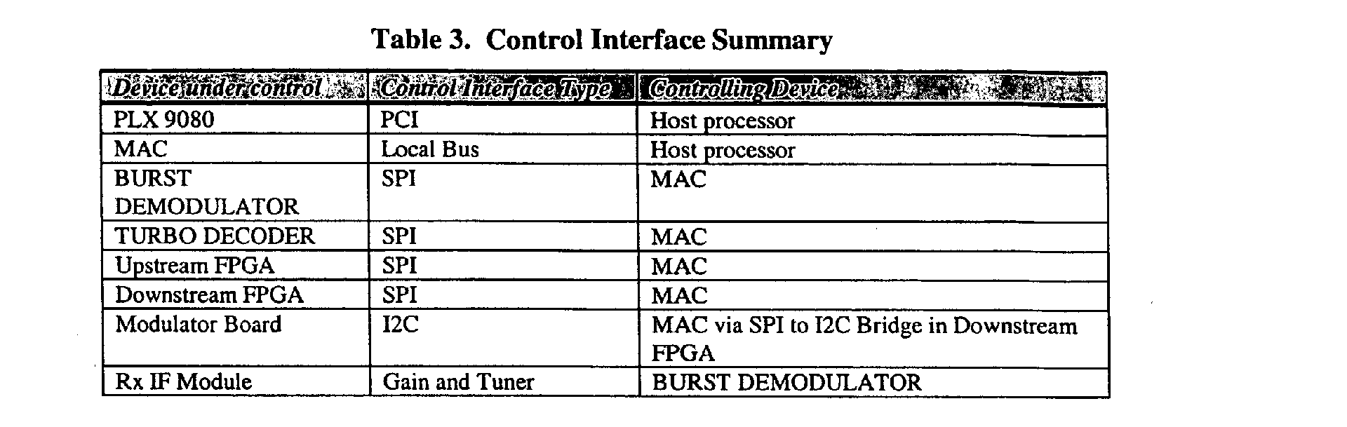
- MAC 310 is controlled by the host 302 via direct PCI memory mapped register accesses.
- the burst demodulator, the turbo decoder, the FPGAs, and the satellite modulator 204 are controlled via an SPI interface of the MAC 310.
- the modulator 204 has an I2C interface, so the SPI input to the downstream FPGA 304 is bridged to the modulator's I2C interface.
- the SPI interface of the MAC can control up to 12 peripherals.
- Programming of downstream and upstream FPGA's 304 and 309 is accomplished via a single on-board FPGA EEPROM. In circuit programming via a JTAG port is also possible for debugging.
- the upstream IF module control signaling for the mixer frequency, and gain setting is handled directly by burst demodulator 306.
- the SMTS produces a modulated IF signal with the specifications of Table 4.
- the SMTS operates at a Burst Error Rate of 10 -4 with the inputs specified in Table 5.
- Upstream performance parameters are engineering estimates based on simulation results.
- the system operates with a maximum round trip transmission delay of 500 ms.
- FIG. 5 is an exemplary block diagram of a MAC 500, according to one embodiment of the present invention.
- SPI controller 514 and DMA engine 512 support a downstream channel and up to eight upstream channels simultaneously through the bus interface 522 and FIFOs 523a and 523b, respectively.
- a JTAG interface 521 is also provided for test and debugging interface.
- Downstream data is read from FIFO 523a by the downstream parser 524.
- the data is then encrypted by DES encryption engine 510 and then CRC headers and Header Check Sum (HCS) are inserted by CRC/HCS insertor 525.
- the encrypted data is then buffered in FIFO 526 and then passed to the Mod interface 531 by the downstream controller 527. Timing signals are provided by the timing generation module 528.
- FIFOs 530 buffer the data received from interface 532.
- Channel arbiter 529 selects the appropriate data channel and DRAM access controller 518 accesses Buffer RAM 519 and Key RAM 520 for appropriate data header insertion before data is sent to the DES decryption engine 511 via FIFO 517 and upstream parser 516.
- CRC and HCS verification on upstream packets CRC/HCS headers are performed by block 515 before data is sent to the bus interface 522.
- the MAC provides the following functionality, among others:
- SMTS MAC has a single upstream channel for normal operation and one for SMTS test mode operation.
- the SMTS MAC interfaces to the upstream interface rather than the burst demodulator 306. This configuration is shown in FIG. 3 with respect to modulator 312.
- the downstream interface is connected to the downstream interface which reformats the MAC serial output into parallel MPEG data.
- the MAC is configured similar to a configuration for a DOCSIS Annex B operation in clock sinking mode.
- the MAC receives its downstream serial interface clock (PSCLK) from the downstream interface of the satellite modulator 204.
- PSCLK downstream serial interface clock
- the MAC interfaces are summarized in Table 6, according to one embodiment of the invention.
- FIG. 6 is an exemplary block diagram of a burst demodulator, according to one embodiment of the present invention.
- the burst demodulator performs the upstream burst demodulator function.
- the burst demodulator is configured to output soft decision data on a pair of test port outputs to the upstream circuit (e.g., 309 in FIG. 3).
- the burst demodulator provides two independent receivers that accept QPSK and m-QAM (Quadrature Amplitude) burst data in frequency-agile, time division multiple access (TDMA) schemes.
- Other capabilities include an analog front end (AFE), a QAM demodulator, a generalized equalizer, and an enhanced Reed Solomon (RS) forward error correction (FEC) decoder with dynamic deinterleaving.
- AFE analog front end
- QAM demodulator a generalized equalizer
- FEC forward error correction
- AFE 611 provides coarse gain setting and analog-to-digital conversion (ADC) on the IF input 611a and I/Q inputs 611b using a FFT processor 633.
- a digital mixer 612 coupled with a DDFS unit 615 translates the desired signal at RF to true DC where the I and Q samples pass through variable decimators (613 & 614), and matched raised-cosine filters 616 & 617.
- a QAM burst demodulator 610 performs word detection of programmable length and pattern in the burst preamble for signal acquisition.
- An adaptive equalizer & Ingress cancellation unit 618 characterizes the RF channel response, cancels ingress noise and removes inter-symbol interference (ISI) caused by micro-reflections in the channel.
- the ranging block 619, preamble process block 620, and tracking loops block 621 help the QAM demodulator 610 and the adaptive equalizer & Ingress cancellation unit 618 perform their respective functions in a timely manner.
- the FEC decoding comprises a programmable de-scrambler 622, a programmable RS decoder 623 with T values programmable up to 16, a byte deinterleaver 625, and FEC interface and FIFOs 624.
- Channel B data is received by receiver 626 and output by the interface 628.
- Timing generation is performed by PLL & timing generator 631.
- a microcontroller interface 630 and external controls 629 are included for smooth programming of the burst controller.
- a JTAG 632 interface is included for test and debugging purposes.
- PHY prepend header output on the burst demodulator MAC/PHY serial output interface 627 to the upstream circuit (309 in FIG. 3).
- Either channel A or channel B data can be mapped to the soft decision output pins, which means that any of the available RF input signal modes can be used on the satellite data.
- the prepend header is modified in the upstream circuit to reflect the results of the RS decoder in that device.
- the burst demodulator is configured for a RS codeword size matching the turbo coded block size of each RS codeword.
- the block size is an integer multiple of 71 bytes, and the error correcting parameter T is set to an arbitrary value of 2. This causes the burst demodulator to output one PHY prepend header per RS codeword.
- the Channel A analog front end of the device is configured to receive the low IF signal produced by the IF module.
- the burst demodulator controls the upstream IF circuit gain and mixer frequency through its external control pins.
- Channel B is configured to either accept a direct RF analog input and use its internal ADC to sample, or configured to accept the 12 bit output from an external ADC.
- the burst demodulator Interfaces are summarized in Table 7, according to one embodiment of the invention.
- the burst demodulator receives a 20.48 MHz from a clock driver on the board when operating Channel A in the low IF mode and when operating Channel B in the analog input direct RF mode.
- Channel B When Channel B is configured to accept input from the external ADC, it receives a 102.4 MHz clock from an external PLL.
- FIG. 7 is an exemplary block diagram of a turbo decoder, according to one embodiment of the present invention.
- the turbo decoder provides the turbo decoding function for the SMTS.
- dual ADCs 710 and 711 sample the baseband IQ analog waveforms.
- the phase & frequency of the sampled waveform is recovered by unit 712, and the resulting signal is demodulated by a variable demodulator 713.
- the phase/frequency recovery module 712 is capable of removing residual phase and frequency offsets in the baseband signal.
- the demodulator signal is then filtered by Nyquist filters 714 and 715. Optimized soft decisions are then fed into either a FEC decoder, or a turbo decoder by a 12-tap FFE unit 716.
- the FEC decoder includes a block header processor 717, an iterative TCM decoder 719, and an RS decoder 725, as shown.
- the turbo decoder includes a Viterbi decoder 718, a synchronization and deinterleaver 721, and a RS decoder 724.
- a deinterleaver RAM 720 stores the appropriate data for iterative TCM decoder 719 and synchronization and deinterleaver 721.
- the error corrected output is delivered in MPEG or DIRECTV transport format through the multiplexor 726.
- Output clock is generated by PLL and clock generation circuit 727. Unit 727 also performs the acquisition and tracking loops functions for the blocks 712 and 713.
- the turbo decoder also includes a simplified user interface including a microcontroller 722 for system configuration, acquisition, control, and monitoring functions. System interface to the turbo decoder in through a simplified high-level application programmer interface (API) 723.
- the turbo decoder also includes a DiSEqC TM controller for two-way communication with LNBs.
- the turbo decoder is used in a mode that bypasses the demodulator circuit as well as the RS decoder.
- Soft decision I and Q symbol data from the burst demodulator, reformatted in the upstream FPGA (309 in FIG. 3), is inserted directly at the input to the turbo decoder block.
- the decoded data is returned to the upstream FPGA via a serial interface.
- An exemplary input block size is 284 symbols. Since the turbo decoder provides the data interface clock to the upstream FPGA without reference to the actual upstream symbol clock, it is programmed to operate at a 5.12 Msym/sec rate.
- the turbo decoder interfaces are summarized in Table 8, according to one embodiment of the invention.
- FIG. 8 is an exemplary block diagram of a Downstream FPGA (e.g., 304 in FIG. 3), according to one embodiment of the present invention.
- the Downstream FPGA converts the MPEG bit stream from the MAC 310 into a byte wide stream for the satellite modulator 204 differential drivers and receivers input 826.
- the byte wide output is synchronized to the byte source clock from the satellite modulator by synchronization block 814.
- the Downstream FPGA connects the MAC downstream interface to a QAM modulator (i.e., 312 in FIG. 3).
- a QAM modulator i.e., 312 in FIG. 3
- An example of this QAM modulator 312 is the BCM3033 Modulator chip from Broadcom Corp.
- the Downstream FPGA also acts as a SPI to I2C bridge using bridge circuitry 810 to convert the SPI format data to I2C data for the I2C differential drivers of the satellite modulator 204.
- Downstream FPGA passes host instructions from the MAC SPI interface to satellite modulator 204.
- the QAM modulator 312 is connected to the Downstream FPGA 304 to facilitate DOCSIS SMTS mode testing.
- the serial bit rate out of the MAC 310 should be great enough to keep up with the expected transmitted bit rate of the QAM modulator 312.
- the maximum bit rate occurs for the 8PSK rate 5/6 Turbo Trellis Code. For example, at 15 Msym/sec, the MAC bit rate is 34 Mbps.
- a pulse swallowed bit clock locked to the byte clock is used to drive the MAC serial interface.
- a visibility port (multiplexor) 816 and a mode control register block 812 provides testing capabilities for the Downstream FPGA.
- the Downstream FPGA provides the interface between the MAC/Demod board in the PCI chassis and the satellite modulator unit.
- the data interface connects to the M2P Interface of the modulator board.
- a single-ended to differential converter between the FPGA and the output connector provides the necessary RS422 differential drive.
- a differential receiver converts the satellite modulator byte clock to a single ended signal for input to the Downstream FPGA.
- the Upstream FPGA (e.g., 309 in FIG. 3) includes the following functions:
- FIG. 9 illustrates an exemplary block diagram of a satellite modem (e.g., 208 in FIG. 2), according to one embodiment of the present invention.
- the satellite modem includes a DOCSIS based circuit 906, which can be a conventional DOCSIS based circuit.
- the DOCSIS based circuit 906 is illustrated as an integrated circuit.
- the DOCSIS based circuit 906 can include a number of integrated circuits and/or discrete circuits and/or software/firmware.
- the DOCSIS based circuit 906 includes a host processor 930 coupled to a DOCSIS based MAC 928.
- the DOCSIS based MAC 928 interfaces with an application executing on the host processor 930.
- the DOCSIS based MAC 928 formats data in accordance with DOCSIS standards.
- the host processor 930 interfaces with a subscriber unit such as a personal computer (not shown in FIG. 9).
- the DOCSIS based circuit 906 further includes a RS encoder 908 and a modulator 932, both of which are described below.
- the DOCSIS based MAC 928 also interfaces with a transmit path and a receive path.
- the receive path includes a downstream tuner 924 and a downstream demodulator 926.
- the transmit path includes the RS encoder 908, the modulator 932, a turbo encoder I-Q interface circuit 910, and an up-converter 914.
- the turbo encoder I-Q interface circuit 910 includes a turbo encoder 902 and an I-Q processing module 904.
- the turbo encoder I-Q interface circuit 910 is illustrated as an integrated circuit. Alternatively, the turbo encoder I-Q interface circuit 910 includes multiple integrated circuits and/or discrete components.
- the transmit and receive paths are coupled to an outdoor unit (ODU) 918, which includes an antenna 920, through a cable interface 922.
- the ODU 918 typically includes a power amplifier in the transmit path.
- Turbo encoding is now described.
- Turbo encoders typically use at least two convolutional component encoders.
- Turbo encoders can also be based on block encoding techniques, such as Hamming codes.
- Turbo codes include, for example, and without limitation, Parallel Concatenated Convolutional Codes (PCCC), Serial Concatenated Convolutional Codes (SCCC), and Hybrid Concatenated Convolutional Codes (HCCC).
- PCCC Parallel Concatenated Convolutional Codes
- SCCC Serial Concatenated Convolutional Codes
- HCCC Hybrid Concatenated Convolutional Codes
- Turbo codes may also be non-systematic. Turbo codes are practical codes due to their performance at low SNR.
- turbo encoders are described in:
- the satellite modem combines an inner turbo code with conventional DOCSIS based RS encoding.
- the satellite modem thus implements a concatenated RS forward error correction (FEC) encoding in the transmit path.
- FEC forward error correction
- Other FEC codes can be used.
- the inner turbo code could be replaced with a conventional convolutional code.
- the outer RS code could be removed leaving only the inner turbo code.
- the latter arrangement is just a subset of the RS-turbo concatenated approach where the error correcting ability "T" of the RS code is set to zero.
- a driving idea in satellite applications is to use FEC codes that allow efficient operation in lower SNR environments than is generally possible with RS codes alone.
- FIG. 10 is an exemplary process flow chart 1000 for modifying DOCSIS transmission paths for wireless environments, according to one embodiment of the present invention.
- the process flowchart 1000 is described with reference to one or more of FIGS. 1-9.
- the process flowchart 1000 is not, however, limited to the examples provided in FIGS. 1-9. Based on the description herein, one skilled in the relevant art(s) will understand that the process flowchart 1000 can be implemented in other environments as well.
- the process begins at block 1002, which includes receiving DOCSIS-compliant data encoded with a RS encoding scheme.
- the turbo encoder I-Q interface 910 receives RS encoded DOCSIS-compliant data 912 from the encoder 908.
- the DOCSIS-compliant data is turbo-encoded.
- the encoder 902 turbo encodes the RS encoded DOCSIS-compliant data 912.
- Block 1006 includes generating baseband-frequency in-phase and quadrature-phase components of the turbo-encoded DOCSIS-compliant data.
- the modulator 932 receives and modulates the data burst 934 in FIG. 9.
- the modulator 932 outputs complex baseband I-Q waveform 936 to the I-Q processing module 904.
- Block 1008 includes interpolating the baseband-frequency in-phase and quadrature-phase components to a common sample rate that is higher than a plurality of DOCSIS-compliant bandwidth sample rates.
- An I and a Q interpolation filters interpolate the complex baseband I-Q waveform 936 to a common sample rate.
- Block 1010 includes digitally pre-compensating the common sample rate baseband-frequency in-phase and quadrature-phase components for impairments encountered in one or more subsequent processes.
- the I-Q processing module 904 may optionally include one or more of the I and Q multiply-by-complex exponentials modules, the I and Q amplitude and phase offset modules, the I and Q x/sin(x) modules, and the I and Q rounding modules.
- Block 1012 includes converting the digitally pre-compensated common sample rate baseband-frequency in-phase and quadrature-phase components to one or more analog signals.
- digital-to-analog conversion is performed within the turbo encoder I-Q interface 910, which can be a single integrated circuit, in the up-converter 914, or in between the turbo encoder I-Q Interface 910 and the up-converter 914.
- Block 1014 includes up-converting the one or more analog signals to a satellite frequency signal.
- up-conversion is performed by the up-converter 914 and the ODU 918. Up-conversion can be performed in a single step or in a plurality of up-conversion steps.
- a combination of the up-converter 914 and the ODU 918 outputs a satellite frequency DOCSIS based signal 942 to the antenna 920.
- RS encoded data is further encoded in an inner turbo code.
- FIG. 11 illustrates how the upstream data is encoded as it passes through the various blocks, according to one embodiment of the present invention.
- TCP/IP transmission control protocol/internet protocol
- Ethernet header information 1104 is prepended to the TCP/IP packet 1102, resulting in an Ethernet frame 1106.
- DOCSIS MAC header information 1108 is appended to the Ethernet frame 1106.
- RS encoding is applied to the DOCSIS packets 1110 by the RS encoder (e.g., 908 in FIG. 9). This results in RS code words 1112.
- the RS code words 1112 are provided to a turbo encoder (e.g., 902 in FIG. 9).
- the RS code words 1112 are encoded by the inner turbo code into turbo code words 1114.
- Optional tailing symbols (TS) are appended to the turbo code words 1114. The tailing symbols are used to drive turbo code blocks to a known state for proper decoding. These count as overhead symbols but not as turbo code word symbols.
- RS code word lengths and turbo code word sizes are preferably selected such that each RS code word results in an integer number of turbo code words. For example, if a rate 1 ⁇ 2 turbo code word size contains 280 QPSK symbols, then the turbo code word contains 280 RS bits (35 bytes) from the outer code and 280 turbo code parity bits. If there are to be two turbo code words per RS code word, then the RS code word size is selected to be 70 bytes. Other sizes and combinations are possible.
- the turbo code words 1114, appended with tailing symbols, are then output from the turbo encoder. A preamble is appended to the turbo code word, resulting in the data burst 1116. This can be performed as in conventional DOCSIS systems.
- the resulting data burst 1016 is modulated in the modulator (e.g., 932 in FIG. 9). Modulation may include symbol mapping, Nyquist filtering and interpolation. Insertion of the preamble may also occur in the modulator 932.
- the modulation can be performed as in conventional DOCSIS systems.
- the modulation provides a complex baseband I-Q waveform (e.g., 936 in FIG. 9) to the I-Q processing module (e.g., 904 in FIG. 9).
- the complex baseband I-Q waveform 336 is provided to the I-Q processing module 904 for further processing.
- FIG. 12 shows simplified downstream processing blocks of a SM, according to one embodiment of the present invention.
- the receiver supports multiple data queues where the data from each queue is transmitted using different modulation and coding depending on the reception capabilities of the intended receiver.
- data intended for receivers with a high SNR can be transmitted using a higher modulation and code rate.
- the data intended for receivers with a low SNR can be transmitted using a lower modulation and code rate.
- the phase & frequency of the data received from tuner 1202 is recovered by frequency/phase recovery unit 1204, and the resulting signal is demodulated by a variable demodulator 1206.
- the demodulated signal is then fed to the multirate turbo decoder 1208 and RS decoded by RS decoder 1210.
- the RS decoded signal is then derandomized by unit 1212, before it is sent to Upstream MAC 1214 and host processor 1216.
- the downstream data stream is composed of map messages (PHY-MAPs) and Superframes, as shown in FIG. 13.
- Each Superframe is composed of an integer number of Queue Blocks (QB), where each Queue Block is a block of data taken from a given queue and transmitted using the modulation and code rate selected for that particular queue.
- QB Queue Blocks
- Superframes can have a variable length depending on the number and type (i.e., modulation and code rate) of Queue Blocks from which it is composed.
- Each Superframe has an associated PHY-MAP that specifies the number and type of Queue Blocks within the Superframe.
- the PHY-MAP is one MPEG frame in length (0x47 sync byte followed by a 3 byte header and 184 bytes of data) and is transmitted using a QPSK rate 1/4 code to ensure that all receivers are able to decode the PHY-MAP (the QPSK rate 1/4 code threshold is 0.4 dB C/N, well below the lowest rate queue of QPSK rate 1/2 with code threshold at 2.2 dB C/N).
- Table 11 specifies an exemplary format of the PHY-MAP, according to one embodiment of the invention.
- the first three bytes are the standard MPEG frame header.
- the 64-bit PHY-MAP unique word is used to identify the PHY-MAP to the receiver.
- the queue block counter is a 16-bit rolling counter that counts the Queue Blocks (QB) being sent through the system.
- the counter value specifies the count for the first QB in the Superframe. This counter is used to sync the receiver to the headend and to make sure that no PHY-MAPs are missed by the receiver.
- the QB descriptor tells the receiver the modulation and code rates for QBs contained in the following Superframe.
- the PHY-MAP terminator specifies the end of useful data in the PHY-MAP. Any additional unused bits in the MPEG frame is zero-padded.
- each QB should be an integer number of RS blocks.
- Table 12 shows an example of possible operating parameters for several multirate queues assuming each QB contains 12 RS blocks.
- Table 13 is an exemplary downstream specifications of input RF interface.
- FIG. 14 shows a block diagram of a direct conversion satellite tuner with I and Q baseband outputs, according to one embodiment of the present invention.
- An exemplary direct conversion satellite tuner is the BCM3440 chip from Broadcom Corp.
- the tuner is capable of selecting channels from the input frequency range of 950 MHz to 2150 MHz and supports applications with output data rates ranging from 1 Mbaud to 45 Mbaud.
- the tuner takes in a differential L-band signal from, for example, standard consumer-grade LNB devices.
- a LNA 1402 is controlled by an automatic gain controller (AGC), (not shown) to provide wide tuner dynamic range.
- a direct conversion architecture is used to convert the L-band signal to in-phase and quadrature base band signals.
- the signals required for direct conversions are generated by a PLL and a quadrature LO generator 1418. These signals are mixed with the L-band input by mixers 1404a and b, and then filtered by low-pas filters 1406a and b to remove the upper image produced by the mixer.
- Variable gain amplifiers 1408a and b are used to adjust the baseband signal levels before processing by the channel selection filters 1410a and b, to optimize noise performance and prevent distortion within the filters.
- Channel selectivity is performed using register programmable 5 th order Butterworth lowpass filters 1410a and b.
- Filter tuning and channel selection are controlled by setting registers using the I2C two-wire serial bus interface 1412.
- DC-Offset correction units 1416a and b correct any DC voltage offset at the inputs of the channel selection filters 1410a and b.
- the satellite tuner supports 8PSK, QPSK, or BPSK demodulation with a nominal AGC range of 60 dB.
- the digital satellite receiver supports QPSK and 8PSK modulation with concatenated RS-turbo decoded error correction coding.
- An exemplary digital satellite receiver is the BCM4510 chip from Broadcom Corp., which is a single chip digital satellite receiver supporting QPSK and 8PSK modulation with concatenated RS- turbo decoded error correction coding.
- the description of this digital satellite receiver is identical to the turbo decoder that was described above in FIG. 7.
- the digital satellite receiver integrates dual 8-bit A/D converters, an all-digital variable rate QPSK/8PSK receiver, a turbo decoder, and a RS decoder. All required RAM is integrated and all required clocks are generated on chip from a single reference crystal.
- the analog waveforms are fed into the receiver, where they are sampled by the integrated A/D converters, digitally mixed to baseband, resampled, and filtered by dual square-root Nyquist filters, as shown in FIG. 7 and described above. Optimized soft decisions are then fed into a turbo/RS decoder. The final error-corrected output is delivered in MPEG-2 transport format.
- the phase/frequency recovery module 712 is capable of removing residual phase and frequency offsets in the baseband signal of up to ⁇ 15 MHz and can track changes in frequency and phase due to local oscillator drift in the tuner and LNB.
- the variable rate filters which are under the control of the symbol timing recovery loop, resample the input data at the correct frequency and phase to ensure that properly sampled symbols are input to the matched filters.
- the matched filters comprise of dual square-root Nyquist filters programmable with a 20%, 25%, or 35% excess bandwidth factor.
- the digital satellite receiver provides a 12-tap decision-directed equalizer. Further, the digital satellite receiver includes two AGC loops which allow the control of both RF and IF variable gain amplifiers (VGAs) in the satellite tuner.
- VGAs variable gain amplifiers
- the amount of gain control allocated to each loop can be set via the host bus interface.
- Each AGC loop examines the power of the digitized baseband input signal and compares it to a programmable loading factor.
- the gain error is fed into a digital loop filter and is converted to an analog voltage by an on-chip delta-sigma modulator and an off-chip passive filter. This voltage may then be used to control a variable gain amplifier or variable attenuator to optimally load the A/D converters.
- This loop may be frozen or reset independent of the other synchronization loops.
Abstract
Description


- Formats downstream data into MPEG frames,
- Inserts DOCSIS Time stamps at programmed intervals,
- Provides an upstream PHY interface for serial data and Maps,
- Provides a downstream PHY serial interface,
- Performs DES encryption and decryption,
- Performs CRC and Header Check Sum (HCS) verification on upstream packets,
- Calculates and inserts CRC and HCS on downstream packets,
- Provides SPI Interface for programming PHY devices, and
- Interfaces to PLX bridge.


http//www331.jpl.nasa.gov/public/TurboForce.GIF, March 3, 2002.
| PHY-MAP Format | ||
| Description | # of bits | Value |
| | 8 | 0x47 |
| | 1 | 0 |
| Payload | 1 | |
| | 1 | 0 |
| | 13 | |
| | 2 | 00 |
| | 2 | 01 |
| | 4 | |
| PHY-MAP Unique Word | 64 | - |
| Queue Block Counter | 16 | - |
| Queue Blocks Descriptor | - | - |
| PHY-MAP Terminator | - | - |
| Example Queue Operating Parameters | ||||
| Modulation / Code Rate | Operating Point (C/N dB) | # RS Blocks per Queue Block | # MPEG Frames per Queue Block | Spectral Efficiency (bits/symbol) |
| | 2.2 | 12 | 78 | 0.881 |
| | 5.1 | 12 | 78 | 1.309 |
| | 7.6 | 12 | 78 | 1.799 |
| | 10.4 | 12 | 78 | 2.159 |

| Parameter | Min. | Typ. | Max | Comments |
| Frequency range (MHz) | 950 | 2150 | ||
| Input Level (dBm) | -70 | -25 | Total input power (22 MHz bandwidth) | |
| Input VSWR | 2.0:1 | 75Ω Source. | ||
| Gain (dB) | 23 | 78 | Controlled via RF and IF AGC signals generated in the satellite receiver |
| Satellite Tuner Key Specifications | ||||
| Gain Variation (dB) | -2 | 2 | ||
| Total spurious at RF input (dBm) | -65 | Spurious generated prefrably, from 950 to 2150 MHz | ||
| Noise Figure (dB) | 10 | 12 | ||
| 3rd Order Intercept Point (dBm) | -31.4 10.6 13.25 |
@ maximum gain, in-band @ minimum gain, in-band @ minimum gain, out-of-band | ||
| LO Step size (MHz) | 2 | 4 | 8 | |
| Phase noise integrated from 2.5 kHz to 41 MHz (degrees rms) | 1.5 | |||
| Phase noise (dBc/Hz) | Phase noise generated by the satellite tuner | |||
| @ 10 kHz offset | -100 | -95 | ||
| @ 100 kHz offset | -100 | -95 | ||
| @ 1 MHz offset | -115 | |||
| LO Lock-up time (ms) | 7 | 10 | ||
| Quadrature Phase Imbalance (degrees) | ±2 | 300 kHz to 22 MHz | ||
| Quadrature Amplitude Imbalance (dB) | ±1 | 300 kHz to 22 MHz | ||
| IF Bandwidth (MHz) | 1 | 36 | Programmable LPF, 1 MHz steps | |
| IF Filter Stop-band Rej. (dB) | -35 | |||
| Amplitude Ripple (dB) | ±1.0 | 300 kHz to 22 MHz | ||
| Group Delay (nsp-p) | 50 | Total variation within IFBW |
| I-Q DATA INTERFACE | ||
| Parameter | Value | Comments |
| IQ Output Level | 1.0 Vpp (typical) | |
| IQ Output Impedance | 250 ohms (typical) | |
| IQ DC output | 1.15 Vdc (typical) | |
| Frequency offset (MHz) | 15 (max) |
Claims (21)
- A satellite communication system comprising:wherein the satellite earth station includes:a satellite earth station operably coupled to at least one data network; anda plurality of satellite modems, each satellite modem of the plurality of satellite modems communicating in an upstream and downstream data communication mode with the satellite earth station via at least one servicing satellite,a host processor for receiving data packets from the at least one data network and processing the Data Over Cable Service Interface Specification (DOCSIS) management packets,a DOCSIS Media Access Control (MAC) coupled to the host processor for encrypting the transmit packet data from the host memory, framing data in MAC headers and inserting MAC timestamps in the transmit packet data,a satellite modulator coupled to the DOCSIS MAC for modulating the encrypted transmit packet data to generate downstream output data for transmission to at least one of the plurality of satellite modems,a burst demodulator for demodulating upstream data received from at least one of the plurality of satellite modems, anda turbo decoder coupled to the burst demodulator and the DOCSIS MAC for decoding the demodulated data from the burst demodulator and sending the decoded data to the DOCSIS MAC, wherein the DOCSIS MAC sends DOCSIS management packets portion of the decoded data to the host processor and sends transmit packet data portion of the decoded data to the at least one data network.
- The satellite communication system of claim 1, wherein the data network is the Ethernet.
- The satellite communication system of claim 1 further comprising an RS Decoder for correcting errors of the decoded signal from the turbo decoder.
- The satellite communication system of claim 1, wherein the DOCSIS MAC comprises:a SPI controller for supporting a downstream channel and at least one upstream channel; an encryption engine for encrypting the downstream data;a decryption engine for decrypting the upstream data;a formatter for formatting downstream data into Motion Picture Expert Group (MPEG) frames; anda timing generator for inserting DOCSIS time stamps at programmable intervals.
- The satellite communication system of claim 1, wherein the burst demodulator comprises:an analog front end (AFE) circuit for accepting an analog input signal and generating a digital signal;a digital filter coupled to the AFE circuit for filtering the digital signal;a quadrature amplitude (QAM) demodulator coupled to the digital filter for word detection of programmable length and pattern in a burst preamble of the digital signal;an adaptive equalizer coupled to the QAM demodulator for characterizing a RF channel response; anda forward error correction (FEC) decoder coupled to the adaptive equalizer for decoding of FEC code.
- The satellite communication system of claim 5, wherein the FEC decoder comprises a programmable de-scrambler; a programmable reed-Solomon (RS) decoder; a byte deinterleaver; and FEC interface circuit.
- The satellite communication system of claim 5, wherein the adaptive equalizer includes an Ingress cancellation circuit for canceling ingress noise and removing inter-symbol interference.
- The satellite communication system of claim 5, further comprising a microcontroller for programming of the burst demodulator.
- The satellite communication system of claim 5, further comprising a channel B input interface configured to accept a direct RF analog input.
- The satellite communication system of claim 1, wherein the turbo decoder comprises:dual analog-to-digital converters (ADCs) for sampling a baseband IQ analog waveform;a phase/frequency recovery circuit coupled to the dual ADCs for recovering the phase and frequency of the sampled waveform;a variable demodulator for demodulating the recovered signal;a forward error correction (FEC) decoder coupled to the demodulator for FEC decoding of the modulated signal; anda turbo decoding circuit coupled to the demodulator for turbo decoding of the modulated signal.
- The satellite communication system of claim 10, wherein the turbo decoding circuit comprises: a Viterbi decoder, a synchronization and deinterleaver, and a reed-Solomon (RS) decoder.
- The satellite communication system of claim 10, further comprising a microcontroller for system configuration, control, and monitoring functions.
- The satellite communication system of claim 10, further comprising a downstream circuit coupled to the DOCSIS MAC for reformatting the data into a byte-wide stream and forwarding the bytes to the satellite modulator.
- A method for a satellite communication in compliance with a Data Over Cable Service Interface Specification (DOCSIS) standard, the method comprising:receiving a radio frequency (RF) upstream signal;demodulating the received RF signal to generate soft decision quadraphase-shift keying (QPSK) output signal;turbo decoding the QPSK output signal;decoding the turbo decoded output signal by a Reed-Solomon (RS) decoder;assembling DOCSIS packets in the RS decoded signal; andforwarding the assembled data to a data network.
- The method of claim 14, further comprising:receiving DOCSIS-compliant data encoded with a Reed-Solomon encoding scheme from the data network;turbo-encoding the DOCSIS-compliant data;generating baseband-frequency in-phase and quadrature-phase components of the turbo-encoded DOCSIS-compliant data;converting the the turbo-encoded DOCSIS-compliant data to one or more analog signals for downstream satellite data transmission.
- The method of claim 15, further comprising interpolating the baseband-frequency in-phase and quadrature-phase components to a common sample rate that is higher than a plurality of DOCSIS-compliant bandwidth sample rates.
- The method of claim 16, further comprising digitally pre-compensating the common sample rate baseband-frequency in-phase and quadrature-phase components for impairments encountered in one or more subsequent processes;
converting digitally pre-compensated common sample rate baseband-frequency in-phase and quadrature-phase components to one or more analog signals; and - A satellite earth station system for upstream and downstream data communication comprising:a host computer coupled to a data network for receiving data packets from a data network and processing the Data Over Cable Service Interface Specification (DOCSIS) management packets;a demodulator/Media Access Control (MAC) card coupled to the host processor including
a DOCSIS MAC coupled to the host computer for encrypting transmit packet data from the data network responsive to the processed DOCSIS management packets from the host computer,
a burst demodulator for demodulating upstream data received from a satellite modem, and
a turbo decoder coupled to the burst demodulator and the DOCSIS MAC for decoding the demodulated data from the burst demodulator and sending the decoded data to the DOCSIS MAC, wherein the DOCSIS MAC sends DOCSIS management packets portion of the decoded data to the host computer and sends transmit packet data portion of the decoded data to the data network; anda satellite modulator coupled to the demodulator/MAC card for modulating the encrypted transmit packet data from the DOCSIS MAC to generate downstream output data for transmission to the satellite modem. - The satellite earth station system of claim 18, wherein the demodulator/MAC card is embodied in a pluggable circuit board card resident in a PCI chassis and the host computer is a personal computer (PC).
- The satellite earth station system of claim 18, wherein the data network is the Ethernet.
- The satellite earth station system of claim 19, wherein the DOCSIS MAC and the PC communicate via a PCI bus.
Applications Claiming Priority (4)
| Application Number | Priority Date | Filing Date | Title |
|---|---|---|---|
| US41087002P | 2002-09-13 | 2002-09-13 | |
| US410870P | 2002-09-13 | ||
| US44858803P | 2003-02-20 | 2003-02-20 | |
| US448588P | 2003-02-20 |
Publications (3)
| Publication Number | Publication Date |
|---|---|
| EP1398891A2 true EP1398891A2 (en) | 2004-03-17 |
| EP1398891A3 EP1398891A3 (en) | 2005-03-09 |
| EP1398891B1 EP1398891B1 (en) | 2009-09-09 |
Family
ID=31891549
Family Applications (1)
| Application Number | Title | Priority Date | Filing Date |
|---|---|---|---|
| EP03020857A Expired - Fee Related EP1398891B1 (en) | 2002-09-13 | 2003-09-15 | High speed data service via satellite modem termination system and satellite modems |
Country Status (3)
| Country | Link |
|---|---|
| US (2) | US7738596B2 (en) |
| EP (1) | EP1398891B1 (en) |
| DE (1) | DE60329147D1 (en) |
Cited By (3)
| Publication number | Priority date | Publication date | Assignee | Title |
|---|---|---|---|---|
| CN110995632A (en) * | 2019-11-29 | 2020-04-10 | 深圳市统先科技股份有限公司 | Satellite communication bandwidth multiplexing circuit |
| WO2020144688A1 (en) * | 2019-01-10 | 2020-07-16 | Satixfy Ltd. | A flexible frame structure for satellite beam-hopping |
| CN113783602A (en) * | 2021-08-31 | 2021-12-10 | 西南电子技术研究所(中国电子科技集团公司第十研究所) | Satellite communication data quality improving device |
Families Citing this family (52)
| Publication number | Priority date | Publication date | Assignee | Title |
|---|---|---|---|---|
| US6987543B1 (en) * | 2000-11-30 | 2006-01-17 | Lsi Logic Corporation | System to efficiently transmit two HDTV channels over satellite using turbo coded 8PSK modulation for DSS compliant receivers |
| US7639617B2 (en) * | 2001-06-27 | 2009-12-29 | Cisco Technology, Inc. | Upstream physical interface for modular cable modem termination system |
| US7688828B2 (en) * | 2001-06-27 | 2010-03-30 | Cisco Technology, Inc. | Downstream remote physical interface for modular cable modem termination system |
| US7209442B1 (en) | 2001-06-27 | 2007-04-24 | Cisco Technology, Inc. | Packet fiber node |
| US7603081B2 (en) * | 2001-09-14 | 2009-10-13 | Atc Technologies, Llc | Radiotelephones and operating methods that use a single radio frequency chain and a single baseband processor for space-based and terrestrial communications |
| US7738596B2 (en) * | 2002-09-13 | 2010-06-15 | Broadcom Corporation | High speed data service via satellite modem termination system and satellite modems |
| US20040136455A1 (en) * | 2002-10-29 | 2004-07-15 | Akhter Mohammad Shahanshah | Efficient bit stream synchronization |
| US7765577B2 (en) | 2002-12-27 | 2010-07-27 | Broadcom Corporation | Turbo coding for upstream and downstream transmission in cable systems |
| US7535863B2 (en) * | 2003-04-21 | 2009-05-19 | Broadcom Corporation | Method and system for adaptive modulation scheduling |
| US7583704B1 (en) | 2003-06-10 | 2009-09-01 | Carl Walker | Synchronizing separated upstream and downstream channels of cable modem termination systems |
| US7650379B2 (en) * | 2003-12-09 | 2010-01-19 | Viasat, Inc. | Method for channel congestion management |
| US8565321B2 (en) * | 2004-03-29 | 2013-10-22 | Broadcom Corporation | Method and system for efficient packing of data across queue blocks in a satellite |
| US7864686B2 (en) * | 2004-05-25 | 2011-01-04 | Cisco Technology, Inc. | Tunneling scheme for transporting information over a cable network |
| US8102854B2 (en) * | 2004-05-25 | 2012-01-24 | Cisco Technology, Inc. | Neighbor discovery proxy with distributed packet inspection scheme |
| US7835274B2 (en) * | 2004-05-25 | 2010-11-16 | Cisco Technology, Inc. | Wideband provisioning |
| US7720101B2 (en) | 2004-05-25 | 2010-05-18 | Cisco Technology, Inc. | Wideband cable modem with narrowband circuitry |
| US7532627B2 (en) * | 2004-05-25 | 2009-05-12 | Cisco Technology, Inc. | Wideband upstream protocol |
| US7817553B2 (en) | 2004-05-25 | 2010-10-19 | Cisco Technology, Inc. | Local area network services in a cable modem network |
| US7646786B2 (en) * | 2004-05-25 | 2010-01-12 | Cisco Technology, Inc. | Neighbor discovery in cable networks |
| US8149833B2 (en) * | 2004-05-25 | 2012-04-03 | Cisco Technology, Inc. | Wideband cable downstream protocol |
| KR100757469B1 (en) * | 2004-06-07 | 2007-09-11 | 삼성전자주식회사 | Digital broadcasting transmission/reception system utilizing null packet and TRS code to improve receiving performance and signal processing method thereof |
| KR101165379B1 (en) * | 2004-07-15 | 2012-07-17 | 삼성전자주식회사 | Digital broadcasting transmission/reception system having improved receiving performance and signal processing method thereof |
| KR100735276B1 (en) * | 2005-08-18 | 2007-07-03 | 삼성전자주식회사 | Method and apparatus for decoding a mpe-fec frame in a dvb-h system |
| US8619876B2 (en) * | 2005-10-11 | 2013-12-31 | Samsung Electronics Co., Ltd. | Method for turbo transmission of digital broadcasting transport stream, a digital broadcasting transmission and reception system, and a signal processing method thereof |
| US8515342B2 (en) * | 2005-10-12 | 2013-08-20 | The Directv Group, Inc. | Dynamic current sharing in KA/KU LNB design |
| JP4690857B2 (en) * | 2005-10-28 | 2011-06-01 | マスプロ電工株式会社 | Bulk transmission system |
| US7957745B2 (en) * | 2005-11-23 | 2011-06-07 | Motorola Mobility, Inc. | Adaptive bearer configuration for broadcast/multicast service |
| US7701951B2 (en) | 2006-03-06 | 2010-04-20 | Cisco Technology, Inc. | Resource reservation and admission control for IP network |
| US20070291947A1 (en) * | 2006-06-19 | 2007-12-20 | Theobold David M | Cryptographically controlled radio transmitter and receiver |
| US8230464B2 (en) * | 2006-09-26 | 2012-07-24 | Viasat, Inc. | DOCSIS MAC chip adapted |
| US8159994B2 (en) * | 2006-09-26 | 2012-04-17 | Viasat, Inc. | High data rate multiplexing satellite stream to low data rate subscriber terminals |
| KR101221913B1 (en) * | 2006-12-20 | 2013-01-15 | 엘지전자 주식회사 | Digital broadcasting system and data processing method |
| US8295166B2 (en) * | 2007-04-17 | 2012-10-23 | Rockwell Automation Technologies, Inc. | High speed industrial control and data acquistion system and method |
| CN101779390B (en) * | 2007-06-29 | 2013-01-02 | Lg电子株式会社 | Broadcast receiving system and method for processing broadcast signals |
| US8320299B2 (en) * | 2007-09-05 | 2012-11-27 | Comtech Ef Data Corp. | Broadband satellite system and method |
| ATE545211T1 (en) * | 2007-09-26 | 2012-02-15 | Nokia Siemens Networks Oy | METHOD AND DEVICE FOR DATA PROCESSING AND COMMUNICATIONS SYSTEM WITH SUCH A DEVICE |
| GB2460416B (en) * | 2008-05-28 | 2010-07-07 | Mirics Semiconductor Ltd | Broadcast receiver system |
| US8401600B1 (en) | 2010-08-02 | 2013-03-19 | Hypres, Inc. | Superconducting multi-bit digital mixer |
| US20130077641A1 (en) * | 2011-09-22 | 2013-03-28 | Harley F. Burger, Jr. | Systems, Circuits and Methods for Time Stamp Based One-Way Communications |
| US10135518B2 (en) * | 2012-11-15 | 2018-11-20 | Novelsat Ltd. | Echo cancellation in communication transceivers |
| EP2963865B1 (en) | 2013-03-15 | 2017-08-09 | Huawei Technologies Co., Ltd. | Optical channel data unit (odu) service transferring device and method |
| CN103918231B (en) | 2013-03-15 | 2016-10-05 | 华为技术有限公司 | A kind of apparatus and method of Optical Channel Data Unit-k operation exchange |
| WO2016113641A1 (en) | 2015-01-14 | 2016-07-21 | Novelsat Ltd. | Echo cancellation with transmitter-side pre-filtering |
| US10129171B2 (en) * | 2015-07-16 | 2018-11-13 | Arris Enterprises Llc | Allocation and scheduling for time and frequency division multiplexing system |
| US20170055031A1 (en) * | 2015-08-19 | 2017-02-23 | Opentv, Inc. | Method to transmit and receive mpeg-ts over a thunderbolt cable |
| US11133840B2 (en) * | 2017-06-30 | 2021-09-28 | Maxlinear, Inc. | Cable modem transceiver, cable modem, cable modem communication system, processor for a cable modem transceiver, method for calibrating a cable modem transceiver, and computer program |
| US10547394B2 (en) * | 2017-07-13 | 2020-01-28 | Benjamin J. Egg | Quad band relay common data link system and method |
| CN110943773B (en) * | 2019-11-26 | 2022-03-01 | 中国电子科技集团公司第五十四研究所 | Satellite broadcast demodulating equipment suitable for fixed wing aircraft platform |
| CN113922860B (en) * | 2021-09-14 | 2022-07-12 | 中国科学院国家空间科学中心 | Satellite-ground measurement, operation and control integrated baseband processing system for small satellite in medium and low orbit |
| CN114938237B (en) * | 2022-05-25 | 2023-06-16 | 中国电子科技集团公司第十研究所 | Method and system for receiving and transmitting satellite high-speed data |
| CN116707622B (en) * | 2023-08-08 | 2023-11-17 | 北京融为科技有限公司 | Distance measurement method based on satellite data transmission and related equipment |
| CN117580148B (en) * | 2024-01-16 | 2024-03-26 | 中国人民解放军陆军航空兵学院 | DDR storage-based high dynamic burst synchronization method |
Citations (4)
| Publication number | Priority date | Publication date | Assignee | Title |
|---|---|---|---|---|
| EP1063801A2 (en) * | 1999-06-21 | 2000-12-27 | Terayon Communication Systems, Inc. | Mixed Docsis 1.0 TDMA burst with SCDMA transmissions on the same frequency channel |
| US6400696B1 (en) * | 2000-11-07 | 2002-06-04 | Space Systems/Loral, Inc. | Bent-pipe satellite system which couples a lan to a gateway and uses a dynamic assignment/multiple access protocol |
| EP1225749A2 (en) * | 2001-01-12 | 2002-07-24 | Broadcom Corporation | Methods and systems for creating an Ethernet upstream and a DOCSIS downstream packet by appending/extracting packet tags for support of remote network functions/packet classification |
| EP1235402A2 (en) * | 2001-02-23 | 2002-08-28 | Terayon Communication Systems, Inc. | Head end receiver for digital data delivery systems using mixed mode SCDMA and TDMA multiplexing |
Family Cites Families (61)
| Publication number | Priority date | Publication date | Assignee | Title |
|---|---|---|---|---|
| FR2675971B1 (en) | 1991-04-23 | 1993-08-06 | France Telecom | CORRECTIVE ERROR CODING METHOD WITH AT LEAST TWO SYSTEMIC CONVOLUTIVE CODES IN PARALLEL, ITERATIVE DECODING METHOD, CORRESPONDING DECODING MODULE AND DECODER. |
| FR2675970B1 (en) | 1991-04-23 | 1993-08-06 | France Telecom | CORRECTIVE CONVOLUTIVE CODING METHOD FOR PSEUDO-SYSTEMATIC ERRORS, DECODING METHOD AND CORRESPONDING DEVICES. |
| FR2675968B1 (en) * | 1991-04-23 | 1994-02-04 | France Telecom | METHOD FOR DECODING A CONVOLUTIVE CODE WITH MAXIMUM LIKELIHOOD AND WEIGHTING OF DECISIONS, AND CORRESPONDING DECODER. |
| FR2712760B1 (en) * | 1993-11-19 | 1996-01-26 | France Telecom | Method for transmitting bits of information by applying concatenated block codes. |
| US5519732A (en) | 1994-05-02 | 1996-05-21 | Harris Corporation | Digital baseband to IF conversion in cellular base stations |
| US6334219B1 (en) * | 1994-09-26 | 2001-12-25 | Adc Telecommunications Inc. | Channel selection for a hybrid fiber coax network |
| AU2588797A (en) * | 1996-03-29 | 1997-10-22 | Motorola, Inc. | Apparatus and method for spectrum management in a multipoint communication system |
| FR2747255B1 (en) * | 1996-04-03 | 1998-07-10 | France Telecom | METHOD AND DEVICE FOR CONVOLUTIVE CODING OF DATA BLOCKS, AND CORRESPONDING DECODING METHOD AND DEVICE |
| FR2753025B1 (en) * | 1996-08-28 | 1998-11-13 | Pyndiah Ramesh | METHOD FOR TRANSMITTING INFORMATION BITS WITH ERROR CORRECTING CODER, ENCODER AND DECODER FOR CARRYING OUT SAID METHOD |
| FR2753026B1 (en) * | 1996-08-28 | 1998-11-13 | Pyndiah Ramesh | METHOD FOR TRANSMITTING INFORMATION BITS WITH ERROR CORRECTING CODER, ENCODER AND DECODER FOR CARRYING OUT SAID METHOD |
| US5926501A (en) * | 1996-12-12 | 1999-07-20 | Motorola, Inc. | Method and apparatus for dynamic channel configuration |
| US6172990B1 (en) * | 1997-06-19 | 2001-01-09 | Xaqti Corporation | Media access control micro-RISC stream processor and method for implementing the same |
| US6584144B2 (en) * | 1997-02-24 | 2003-06-24 | At&T Wireless Services, Inc. | Vertical adaptive antenna array for a discrete multitone spread spectrum communications system |
| US6359923B1 (en) * | 1997-12-18 | 2002-03-19 | At&T Wireless Services, Inc. | Highly bandwidth efficient communications |
| US7002941B1 (en) * | 1997-10-14 | 2006-02-21 | Alvarion Israel (2003) Ltd. | Method and apparatus for synchronizing fast ethernet data packets to radio frames in a wireless metropolitan area network |
| US6070074A (en) * | 1998-04-24 | 2000-05-30 | Trw Inc. | Method for enhancing the performance of a regenerative satellite communications system |
| CA2237264A1 (en) * | 1998-05-08 | 1999-11-08 | Northern Telecom Limited | Receiver based congestion control |
| CN1257382A (en) * | 1998-07-24 | 2000-06-21 | 休斯电子公司 | Frame formatting for aerial interface |
| ATE412289T1 (en) * | 1998-10-30 | 2008-11-15 | Broadcom Corp | CABLE MODEM SYSTEM |
| US7933295B2 (en) * | 1999-04-13 | 2011-04-26 | Broadcom Corporation | Cable modem with voice processing capability |
| US7110434B2 (en) * | 1999-08-31 | 2006-09-19 | Broadcom Corporation | Cancellation of interference in a communication system with application to S-CDMA |
| US6993007B2 (en) * | 1999-10-27 | 2006-01-31 | Broadcom Corporation | System and method for suppressing silence in voice traffic over an asynchronous communication medium |
| EP1254544B1 (en) * | 1999-12-03 | 2015-04-29 | Broadcom Corporation | Embedded training sequences for carrier acquisition and tracking |
| US8151306B2 (en) * | 2000-01-14 | 2012-04-03 | Terayon Communication Systems, Inc. | Remote control for wireless control of system including home gateway and headend, either or both of which have digital video recording functionality |
| WO2001056180A1 (en) * | 2000-01-26 | 2001-08-02 | Vyyo, Ltd. | Two-dimensional scheduling scheme for a broadband wireless access system |
| WO2001056200A1 (en) * | 2000-01-26 | 2001-08-02 | Vyyo, Ltd. | A unidirectional communication scheme for remote maintenance and co ntrol in a broadband wireless access system |
| EP1256206A1 (en) * | 2000-02-17 | 2002-11-13 | Conexant Systems, Inc. | Modem cable avec un controleur d'acces au media programmable |
| US7000031B2 (en) * | 2000-04-07 | 2006-02-14 | Broadcom Corporation | Method of providing synchronous transport of packets between asynchronous network nodes in a frame-based communications network |
| US6853680B1 (en) * | 2000-05-10 | 2005-02-08 | Bigband Networks Bas, Inc. | System and process for embedded cable modem in a cable modem termination system to enable diagnostics and monitoring |
| EP1299965A4 (en) | 2000-05-12 | 2005-02-02 | Henry Ewen | Data transmission system and method |
| US7050402B2 (en) * | 2000-06-09 | 2006-05-23 | Texas Instruments Incorporated | Wireless communications with frequency band selection |
| US6741555B1 (en) * | 2000-06-14 | 2004-05-25 | Nokia Internet Communictions Inc. | Enhancement of explicit congestion notification (ECN) for wireless network applications |
| US6807193B1 (en) | 2000-06-20 | 2004-10-19 | 3Com Corporation | Cable modem with dribble grant access system and method |
| US6598203B1 (en) * | 2000-06-28 | 2003-07-22 | Northrop Grumman Corporation | Parallel punctured convolutional encoder |
| US6898182B1 (en) * | 2000-07-21 | 2005-05-24 | Arris International, Inc | Congestion control in a network device having a buffer circuit |
| US6801537B1 (en) * | 2000-09-07 | 2004-10-05 | Nortel Networks Limited | Adaptive contention algorithm based on truncated binary exponential back-off |
| US6742187B1 (en) * | 2000-09-15 | 2004-05-25 | 3Com Corporation | Upstream bandwidth allocation map (MAP)-initiated channel change method for data-over-cable systems |
| US7139247B2 (en) * | 2000-09-22 | 2006-11-21 | Narad Networks, Inc. | Broadband system with topology discovery |
| US6690655B1 (en) * | 2000-10-19 | 2004-02-10 | Motorola, Inc. | Low-powered communication system and method of operation |
| US7203158B2 (en) * | 2000-12-06 | 2007-04-10 | Matsushita Electric Industrial Co., Ltd. | OFDM signal transmission system, portable terminal, and e-commerce system |
| US6977741B2 (en) * | 2000-12-21 | 2005-12-20 | Xerox Corporation | Progressive image shift for a saddle-stitched document |
| US6804532B1 (en) * | 2000-12-22 | 2004-10-12 | Cisco Technology, Inc. | System and method for re-routing communications based on wireless communication link quality |
| US7058147B2 (en) * | 2001-02-28 | 2006-06-06 | At&T Corp. | Efficient reduced complexity windowed optimal time domain equalizer for discrete multitone-based DSL modems |
| US6891841B2 (en) * | 2001-03-12 | 2005-05-10 | Advent Networks, Inc. | Time division multiple access over broadband modulation method and apparatus |
| US6987778B2 (en) * | 2001-05-22 | 2006-01-17 | Qualcomm Incorporated | Enhanced channel interleaving for optimized data throughput |
| US7104534B2 (en) * | 2001-06-08 | 2006-09-12 | Broadcom Corporation | System and method for detecting collisions in a shared communications medium |
| JP3612563B2 (en) * | 2001-09-07 | 2005-01-19 | 独立行政法人情報通信研究機構 | Multi-mode block coding modulation demodulation method |
| US7379472B2 (en) * | 2001-09-27 | 2008-05-27 | Broadcom Corporation | Hardware filtering of unsolicited grant service extended headers |
| US20030069926A1 (en) * | 2001-10-09 | 2003-04-10 | Weaver Jeffrey Charles | System and method for managing an exchange between a gateway server and a client-side module |
| US7353004B2 (en) * | 2001-11-01 | 2008-04-01 | Broadlogic Network Technologies, Inc. | Multi-channel broadband content distribution system |
| US6954885B2 (en) * | 2001-12-14 | 2005-10-11 | Qualcomm Incorporated | Method and apparatus for coding bits of data in parallel |
| US7020110B2 (en) * | 2002-01-08 | 2006-03-28 | Qualcomm Incorporated | Resource allocation for MIMO-OFDM communication systems |
| US7319666B2 (en) * | 2002-02-06 | 2008-01-15 | Thomson Licensing | Method and apparatus for concatenating and piggybacking data packets |
| US7197276B2 (en) * | 2002-03-15 | 2007-03-27 | Broadcom Corporation | Downstream adaptive modulation in broadband communications systems |
| US8010040B2 (en) * | 2002-04-23 | 2011-08-30 | Broadcom Corporation | Queue depth extended headers for DOCSIS based broadband communication systems |
| US8098606B2 (en) * | 2002-04-23 | 2012-01-17 | Broadcom Corporation | Modified upstream channel descriptor messages for DOCSIS-based broadband communication systems |
| WO2003092202A2 (en) * | 2002-04-23 | 2003-11-06 | Broadcom Corporation | Explicit congestion notification for docsis based broadband communication systems |
| US7729373B2 (en) * | 2002-07-02 | 2010-06-01 | Broadcom Corporation | Modified range requests enabling bandwidth requests and state of health reporting |
| US7694210B2 (en) | 2002-07-31 | 2010-04-06 | Broadcom Corporation | Turbo-coding DOCSIS information for satellite communication |
| US7738596B2 (en) * | 2002-09-13 | 2010-06-15 | Broadcom Corporation | High speed data service via satellite modem termination system and satellite modems |
| EP1528702B1 (en) * | 2003-11-03 | 2008-01-23 | Broadcom Corporation | FEC (forward error correction) decoding with dynamic parameters |
-
2003
- 2003-09-12 US US10/661,648 patent/US7738596B2/en not_active Expired - Fee Related
- 2003-09-15 EP EP03020857A patent/EP1398891B1/en not_active Expired - Fee Related
- 2003-09-15 DE DE60329147T patent/DE60329147D1/en not_active Expired - Lifetime
-
2010
- 2010-06-11 US US12/813,935 patent/US8718182B2/en not_active Expired - Fee Related
Patent Citations (4)
| Publication number | Priority date | Publication date | Assignee | Title |
|---|---|---|---|---|
| EP1063801A2 (en) * | 1999-06-21 | 2000-12-27 | Terayon Communication Systems, Inc. | Mixed Docsis 1.0 TDMA burst with SCDMA transmissions on the same frequency channel |
| US6400696B1 (en) * | 2000-11-07 | 2002-06-04 | Space Systems/Loral, Inc. | Bent-pipe satellite system which couples a lan to a gateway and uses a dynamic assignment/multiple access protocol |
| EP1225749A2 (en) * | 2001-01-12 | 2002-07-24 | Broadcom Corporation | Methods and systems for creating an Ethernet upstream and a DOCSIS downstream packet by appending/extracting packet tags for support of remote network functions/packet classification |
| EP1235402A2 (en) * | 2001-02-23 | 2002-08-28 | Terayon Communication Systems, Inc. | Head end receiver for digital data delivery systems using mixed mode SCDMA and TDMA multiplexing |
Cited By (4)
| Publication number | Priority date | Publication date | Assignee | Title |
|---|---|---|---|---|
| WO2020144688A1 (en) * | 2019-01-10 | 2020-07-16 | Satixfy Ltd. | A flexible frame structure for satellite beam-hopping |
| CN110995632A (en) * | 2019-11-29 | 2020-04-10 | 深圳市统先科技股份有限公司 | Satellite communication bandwidth multiplexing circuit |
| CN113783602A (en) * | 2021-08-31 | 2021-12-10 | 西南电子技术研究所(中国电子科技集团公司第十研究所) | Satellite communication data quality improving device |
| CN113783602B (en) * | 2021-08-31 | 2023-07-11 | 西南电子技术研究所(中国电子科技集团公司第十研究所) | Satellite communication data quality improving device |
Also Published As
| Publication number | Publication date |
|---|---|
| DE60329147D1 (en) | 2009-10-22 |
| US20040105403A1 (en) | 2004-06-03 |
| US7738596B2 (en) | 2010-06-15 |
| US8718182B2 (en) | 2014-05-06 |
| US20100278098A1 (en) | 2010-11-04 |
| EP1398891B1 (en) | 2009-09-09 |
| EP1398891A3 (en) | 2005-03-09 |
Similar Documents
| Publication | Publication Date | Title |
|---|---|---|
| EP1398891B1 (en) | High speed data service via satellite modem termination system and satellite modems | |
| US9197366B2 (en) | FEC (forward error correction) decoder with dynamic parameters | |
| EP1157503B1 (en) | Method and apparatus for communicating between a client device and a linear broadband network | |
| US7835314B2 (en) | Physical layer interface system and method for a wireless communication system | |
| US8811271B2 (en) | Downstream time domain based adaptive modulation for DOCSIS based applications | |
| US7050419B2 (en) | Head end receiver for digital data delivery systems using mixed mode SCDMA and TDMA multiplexing | |
| US6754872B2 (en) | Method and apparatus for reducing channel distortion in a wireless communications network | |
| US20100262895A1 (en) | Turbo-Coding DOCSIS Information for Satellite Communications | |
| US8730865B2 (en) | Front-end for satellite communication | |
| US7006560B2 (en) | Digital modem | |
| US7505531B1 (en) | Signal communications system and method for noisy links | |
| US11296920B2 (en) | High-speed serial interface for orthogonal frequency division multiplexing (OFDM) cable modems | |
| Karam et al. | A variable-rate QPSK demodulator for digital satellite TV reception | |
| Lu et al. | A single-chip universal burst receiver for cable modem/digital cable-TV applications | |
| Fischer | Broadband Cable Transmission According to DVB-C | |
| Winduratna et al. | Enhancements for the broadband satellite network architecture | |
| de Bot | European Transmission Standards for Digital TV Broadcasting |
Legal Events
| Date | Code | Title | Description |
|---|---|---|---|
| PUAI | Public reference made under article 153(3) epc to a published international application that has entered the european phase |
Free format text: ORIGINAL CODE: 0009012 |
|
| AK | Designated contracting states |
Kind code of ref document: A2 Designated state(s): AT BE BG CH CY CZ DE DK EE ES FI FR GB GR HU IE IT LI LU MC NL PT RO SE SI SK TR |
|
| AX | Request for extension of the european patent |
Extension state: AL LT LV MK |
|
| PUAL | Search report despatched |
Free format text: ORIGINAL CODE: 0009013 |
|
| AK | Designated contracting states |
Kind code of ref document: A3 Designated state(s): AT BE BG CH CY CZ DE DK EE ES FI FR GB GR HU IE IT LI LU MC NL PT RO SE SI SK TR |
|
| AX | Request for extension of the european patent |
Extension state: AL LT LV MK |
|
| RIC1 | Information provided on ipc code assigned before grant |
Ipc: 7H 04B 7/185 A Ipc: 7H 04L 29/06 B |
|
| 17P | Request for examination filed |
Effective date: 20050909 |
|
| AKX | Designation fees paid |
Designated state(s): DE FR GB |
|
| 17Q | First examination report despatched |
Effective date: 20060717 |
|
| GRAP | Despatch of communication of intention to grant a patent |
Free format text: ORIGINAL CODE: EPIDOSNIGR1 |
|
| RAP1 | Party data changed (applicant data changed or rights of an application transferred) |
Owner name: GIN, ALAN Owner name: FANOUS, ADEL F. Owner name: LIN, DOROTHY D. Owner name: DALE, MARK R. Owner name: BROADCOM CORPORATION Owner name: BRESCIA, ROCCO J., JR. Owner name: CHIEN, JEN-CHIEH |
|
| GRAS | Grant fee paid |
Free format text: ORIGINAL CODE: EPIDOSNIGR3 |
|
| RAP1 | Party data changed (applicant data changed or rights of an application transferred) |
Owner name: BROADCOM CORPORATION Owner name: DALE, MARK R. |
|
| GRAA | (expected) grant |
Free format text: ORIGINAL CODE: 0009210 |
|
| AK | Designated contracting states |
Kind code of ref document: B1 Designated state(s): DE FR GB |
|
| REG | Reference to a national code |
Ref country code: GB Ref legal event code: FG4D |
|
| REF | Corresponds to: |
Ref document number: 60329147 Country of ref document: DE Date of ref document: 20091022 Kind code of ref document: P |
|
| PLBE | No opposition filed within time limit |
Free format text: ORIGINAL CODE: 0009261 |
|
| STAA | Information on the status of an ep patent application or granted ep patent |
Free format text: STATUS: NO OPPOSITION FILED WITHIN TIME LIMIT |
|
| 26N | No opposition filed |
Effective date: 20100610 |
|
| REG | Reference to a national code |
Ref country code: FR Ref legal event code: ST Effective date: 20110422 |
|
| PG25 | Lapsed in a contracting state [announced via postgrant information from national office to epo] |
Ref country code: FR Free format text: LAPSE BECAUSE OF NON-PAYMENT OF DUE FEES Effective date: 20091109 |
|
| PGFP | Annual fee paid to national office [announced via postgrant information from national office to epo] |
Ref country code: GB Payment date: 20160927 Year of fee payment: 14 |
|
| REG | Reference to a national code |
Ref country code: DE Ref legal event code: R082 Ref document number: 60329147 Country of ref document: DE Representative=s name: BOSCH JEHLE PATENTANWALTSGESELLSCHAFT MBH, DE Ref country code: DE Ref legal event code: R081 Ref document number: 60329147 Country of ref document: DE Owner name: AVAGO TECHNOLOGIES INTERNATIONAL SALES PTE. LT, SG Free format text: FORMER OWNERS: BROADCOM CORP., IRVINE, CALIF., US; DALE, MARK R., IRVINE, CALIF., US Ref country code: DE Ref legal event code: R081 Ref document number: 60329147 Country of ref document: DE Owner name: AVAGO TECHNOLOGIES GENERAL IP (SINGAPORE) PTE., SG Free format text: FORMER OWNERS: BROADCOM CORP., IRVINE, CALIF., US; DALE, MARK R., IRVINE, CALIF., US |
|
| GBPC | Gb: european patent ceased through non-payment of renewal fee |
Effective date: 20170915 |
|
| PG25 | Lapsed in a contracting state [announced via postgrant information from national office to epo] |
Ref country code: GB Free format text: LAPSE BECAUSE OF NON-PAYMENT OF DUE FEES Effective date: 20170915 |
|
| REG | Reference to a national code |
Ref country code: DE Ref legal event code: R082 Ref document number: 60329147 Country of ref document: DE Representative=s name: BOSCH JEHLE PATENTANWALTSGESELLSCHAFT MBH, DE Ref country code: DE Ref legal event code: R081 Ref document number: 60329147 Country of ref document: DE Owner name: AVAGO TECHNOLOGIES INTERNATIONAL SALES PTE. LT, SG Free format text: FORMER OWNER: AVAGO TECHNOLOGIES GENERAL IP (SINGAPORE) PTE. LTD., SINGAPORE, SG |
|
| PGFP | Annual fee paid to national office [announced via postgrant information from national office to epo] |
Ref country code: DE Payment date: 20200930 Year of fee payment: 18 |
|
| REG | Reference to a national code |
Ref country code: DE Ref legal event code: R119 Ref document number: 60329147 Country of ref document: DE |
|
| PG25 | Lapsed in a contracting state [announced via postgrant information from national office to epo] |
Ref country code: DE Free format text: LAPSE BECAUSE OF NON-PAYMENT OF DUE FEES Effective date: 20220401 |