EP1396239B1 - Delivery system for delivering a self-expanding stent - Google Patents
Delivery system for delivering a self-expanding stent Download PDFInfo
- Publication number
- EP1396239B1 EP1396239B1 EP02020170A EP02020170A EP1396239B1 EP 1396239 B1 EP1396239 B1 EP 1396239B1 EP 02020170 A EP02020170 A EP 02020170A EP 02020170 A EP02020170 A EP 02020170A EP 1396239 B1 EP1396239 B1 EP 1396239B1
- Authority
- EP
- European Patent Office
- Prior art keywords
- stent
- delivery system
- end portion
- retraction
- tube
- Prior art date
- Legal status (The legal status is an assumption and is not a legal conclusion. Google has not performed a legal analysis and makes no representation as to the accuracy of the status listed.)
- Expired - Lifetime
Links
Images
Classifications
-
- A—HUMAN NECESSITIES
- A61—MEDICAL OR VETERINARY SCIENCE; HYGIENE
- A61F—FILTERS IMPLANTABLE INTO BLOOD VESSELS; PROSTHESES; DEVICES PROVIDING PATENCY TO, OR PREVENTING COLLAPSING OF, TUBULAR STRUCTURES OF THE BODY, e.g. STENTS; ORTHOPAEDIC, NURSING OR CONTRACEPTIVE DEVICES; FOMENTATION; TREATMENT OR PROTECTION OF EYES OR EARS; BANDAGES, DRESSINGS OR ABSORBENT PADS; FIRST-AID KITS
- A61F2/00—Filters implantable into blood vessels; Prostheses, i.e. artificial substitutes or replacements for parts of the body; Appliances for connecting them with the body; Devices providing patency to, or preventing collapsing of, tubular structures of the body, e.g. stents
- A61F2/95—Instruments specially adapted for placement or removal of stents or stent-grafts
- A61F2/962—Instruments specially adapted for placement or removal of stents or stent-grafts having an outer sleeve
- A61F2/966—Instruments specially adapted for placement or removal of stents or stent-grafts having an outer sleeve with relative longitudinal movement between outer sleeve and prosthesis, e.g. using a push rod
Definitions
- the present invention relates to a delivery system for delivering a self-expanding stent according to the preamble part of claim 1.
- Such a delivery system is known from WO 98/23241.
- a self-expanding stent is a stent which expands from a compressed delivery position to its original diameter when released from the delivery device, exerting radial force on the constricted portion of the body lumen to re-establish patency.
- One common self-expanding stent is manufactured of nitinol, a nickel-titanium shape memory alloy, which can be formed and annealed, deformed at a low temperature, and recalled to its original shape with heating, such as when deployed at body temperature in the body.
- the delivery system comprises a retractable outer sheath that is divided into an outer tube and a separate inner tube. Said tubes are disposed concentrically with respect to each other.
- the outer tube surrounds and covers the stent along its entire length whilst the separate inner tube surrounds the stent only partly, as especially along about 40% to 60%, and more specifically only along about 50 % of its entire length.
- a specifically advantageous embodiment provides for an arrangement of stop members.
- One of said stop members can be disposed at the distal end of a retraction tube of the retraction handle whilst the second stop member is disposed at the proximal end portion of the inner tube. So, upon operation of the retraction handle the outer tube is retracted and after a predetermined length of retraction the stop members engage each other so that also the inner tube can be retracted upon only one operation of the retraction handle so that the physician can deploy the stent with the same kind of operation as with conventional delivery systems but much smoother and with lower retraction forces. This facilitates an exact position of the stent as the stent is prevented from being longitudinally compressed.
- the outer tube may be a co-extruded tubing, e. g. made from polyamide whilst the inner tubing is preferably made from polyethylene.
- the materials of the tubes are to be chosen from combinations of materials that result in low friction resistance or are tubings comprising layers with low friction coefficients.
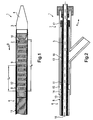
- Figs. 1 and 2 show side views of the inventive delivery system 1.
- the delivery system 1 is intended for delivering a self-expanding stent 2 shown in Fig. 1.
- the delivery system 1 comprises a catheter body 3 having a proximal end 5 and a distal end 4.
- the catheter body 3 is adapted to transport the stent 2 to a predetermined site in a body lumen for deployment that is not shown in Figs. 1 and 2.
- the catheter body 3 furthermore, comprises a metal and/or a metal-polymeric and/or a polymere shaft 18 that extends from the proximal end 5 to the distal end 4.
- the delivery system 1 furthermore, comprises a retractable outer sheath 6 shown in Figs. 1 and 2 that surrounds the stent 2 and contains the stent 2 in a delivery configuration where the stent 2 has a reduced radius along its entire length L E shown in Fig. 1.
- Fig. 2 shows a proximal retraction handle 7 that may be configured as an integral part of a so-called tuohy borst valve.
- the handle 7 is disposed at the proximal end 5 of the catheter body 3 as shown in Fig. 2.
- the sheath 6 is a combination of an outer tube 8 and a separate inner tube 11.
- the outer tube 8 has a distal end portion 9 that surrounds the stent 2 along its entire length L E as can be learned from Fig. 1.
- the outer tube 8 furthermore, comprises a proximal end portion 10 being connected to the retraction handle 7, e.g. by an adhesive connection.
- the separate inner tube 11 is disposed concentrically within the outer tube 8 and does concentrically surround metal shaft 18 of catheter body 3.
- the inner tube 11 comprises a distal end portion 12 surrounding the stent 2 only along a part L P of its entire length L E as can be seen form Fig. 1. This configuration significantly reduces the friction forces between the stent 2 and the outer sheath 6 so that the forces for retraction of the outer sheath 6 become remarkably smaller in comparison to conventional delivery systems.
- the handle 7 of the preferred embodiment shown in figs. 1 and 2 comprises a retraction tube 13 that is connected at its distal end 14 to the proximal end portion 10 of the outer tube 8.
- the retraction tube 13 comprises a stop member 15 at its distal end 14 (see Fig. 2).
- Said stop member 15 can be configured as an annular ring extending inwardly from the inner periphery of retraction tube 13.
- the retraction tube 13 concentrically surrounds the proximal end portion 5 of catheter body 3 and proximal end portion 16 of the inner tube 11.
- the inner tube 11 in turn, comprises a stop member 17 at its proximal end portion 16.
- Said stop member 17 may also be configured as an annular ring extending outwardly from the outer periphery of inner tube 11.
- the stop members 15 and 17 are adapted to be engaged with one another upon retraction of handle 17.
- outer tube 8 is pulled back in the direction of arrow B shown in Fig. 1 sliding partly on inner tube 11 as said inner tube 11 covers only a part of stent 2.
- inner tube 11 is also pulled back in the direction of arrow B shown in Fig. 1 so that stent 2 can be released and deployed at a predetermined site in a body lumen.
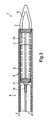
- Fig. 3 depicts a second embodiment of a delivery system 1 according to the present invention. All parts of this embodiment being similar to the embodiment of Figs. 1 and 2 are designated by the same reference numerals.
Abstract
Description
- The present invention relates to a delivery system for delivering a self-expanding stent according to the preamble part of claim 1.
- Such a delivery system is known from WO 98/23241.
- Delivery systems for deploying endovascular stent grafts, self-expanding stents or balloon expandable stents are well-known in the field of medical technology. As has been explained in the before-mentioned citation a self-expanding stent is a stent which expands from a compressed delivery position to its original diameter when released from the delivery device, exerting radial force on the constricted portion of the body lumen to re-establish patency. One common self-expanding stent is manufactured of nitinol, a nickel-titanium shape memory alloy, which can be formed and annealed, deformed at a low temperature, and recalled to its original shape with heating, such as when deployed at body temperature in the body.
- One important factor in delivering the stent is a controlled precise retraction of the retractable outer sheath. What is needed is a delivery system which provides for a controlled and precise retraction of the retractable outer sheath and enabled the physician to accurately determine proper positioning of the stent, as well as track the retraction of the outer sheath.
- Known delivery systems suffer, however, from the draw-back that the retraction forces are often too high, especially in cases where the stents are covered with layers made from body-compatible materials or the like so that the friction forces between the stent and the outer sheath may become excessively high.
- It is therefore an object underlying the present invention to provide a delivery system for delivering a self-expanding stent that is able to overcome the before-mentioned draw-back so that a smooth retraction of the retractable outer sheath is possible.
- The solution of this object is achieved by the features of claim 1.
- The delivery system according to the present invention comprises a retractable outer sheath that is divided into an outer tube and a separate inner tube. Said tubes are disposed concentrically with respect to each other. The outer tube surrounds and covers the stent along its entire length whilst the separate inner tube surrounds the stent only partly, as especially along about 40% to 60%, and more specifically only along about 50 % of its entire length.
- This simple and effective arrangement results in the advantage that the surface between the stent and the outer sheath is reduced by a remarkable percentage, especially up to 50 %, so that the retraction forces become significantly smaller.
- The dependent claims contain advantageous embodiments of the present invention.
- A specifically advantageous embodiment provides for an arrangement of stop members. One of said stop members can be disposed at the distal end of a retraction tube of the retraction handle whilst the second stop member is disposed at the proximal end portion of the inner tube. So, upon operation of the retraction handle the outer tube is retracted and after a predetermined length of retraction the stop members engage each other so that also the inner tube can be retracted upon only one operation of the retraction handle so that the physician can deploy the stent with the same kind of operation as with conventional delivery systems but much smoother and with lower retraction forces. This facilitates an exact position of the stent as the stent is prevented from being longitudinally compressed.
- According to the present invention, the outer tube may be a co-extruded tubing, e. g. made from polyamide whilst the inner tubing is preferably made from polyethylene.
- In general, the materials of the tubes are to be chosen from combinations of materials that result in low friction resistance or are tubings comprising layers with low friction coefficients.
- A detailed description of the invention is described below with a specific reference being made to the drawings in which:
- Fig. 1
- is a schematically simplified view of the distal end portion of the delivery system according to the present invention,
- Fig. 2
- is a schematically simplified view of the proximal end portion of the delivery system according to the present invention, and
- Fig. 3
- is a schematically simplified view, similar to Fig. 1, of the distal end portion of the second embodiment of the delivery system according to the present invention.
- While this invention may be embodied in many different forms, there is shown in the drawings and described in detail herein a specific preferred embodiment of the invention. The present disclosure is an exemplification of the principles of the invention and is not intended to limit the invention to the particular embodiment illustrated.
- Figs. 1 and 2 show side views of the inventive delivery system 1.
- The delivery system 1 is intended for delivering a self-expanding
stent 2 shown in Fig. 1. - The delivery system 1 comprises a catheter body 3 having a
proximal end 5 and adistal end 4. The catheter body 3 is adapted to transport thestent 2 to a predetermined site in a body lumen for deployment that is not shown in Figs. 1 and 2. - The catheter body 3, furthermore, comprises a metal and/or a metal-polymeric and/or a
polymere shaft 18 that extends from theproximal end 5 to thedistal end 4. - The delivery system 1, furthermore, comprises a retractable outer sheath 6 shown in Figs. 1 and 2 that surrounds the
stent 2 and contains thestent 2 in a delivery configuration where thestent 2 has a reduced radius along its entire length LE shown in Fig. 1. - Fig. 2 shows a proximal retraction handle 7 that may be configured as an integral part of a so-called tuohy borst valve.
- The handle 7 is disposed at the
proximal end 5 of the catheter body 3 as shown in Fig. 2. - According to the present invention the sheath 6 is a combination of an
outer tube 8 and a separateinner tube 11. Theouter tube 8 has adistal end portion 9 that surrounds thestent 2 along its entire length LE as can be learned from Fig. 1. - The
outer tube 8, furthermore, comprises aproximal end portion 10 being connected to the retraction handle 7, e.g. by an adhesive connection. - The separate
inner tube 11 is disposed concentrically within theouter tube 8 and does concentricallysurround metal shaft 18 of catheter body 3. Theinner tube 11 comprises adistal end portion 12 surrounding thestent 2 only along a part LP of its entire length LE as can be seen form Fig. 1. This configuration significantly reduces the friction forces between thestent 2 and the outer sheath 6 so that the forces for retraction of the outer sheath 6 become remarkably smaller in comparison to conventional delivery systems. - The handle 7 of the preferred embodiment shown in figs. 1 and 2 comprises a
retraction tube 13 that is connected at itsdistal end 14 to theproximal end portion 10 of theouter tube 8. Theretraction tube 13 comprises astop member 15 at its distal end 14 (see Fig. 2). Saidstop member 15 can be configured as an annular ring extending inwardly from the inner periphery ofretraction tube 13. - As can be seen from Fig. 2 the
retraction tube 13 concentrically surrounds theproximal end portion 5 of catheter body 3 andproximal end portion 16 of theinner tube 11. - The
inner tube 11, in turn, comprises astop member 17 at itsproximal end portion 16. Saidstop member 17 may also be configured as an annular ring extending outwardly from the outer periphery ofinner tube 11. - As can be seen from Fig. 2 the
stop members handle 17. When operating saidretraction tube 13 of handle 7 in the direction of arrow A in Fig. 2outer tube 8 is pulled back in the direction of arrow B shown in Fig. 1 sliding partly oninner tube 11 as saidinner tube 11 covers only a part ofstent 2. Upon engagement ofstop members inner tube 11 is also pulled back in the direction of arrow B shown in Fig. 1 so thatstent 2 can be released and deployed at a predetermined site in a body lumen. - Fig. 3 depicts a second embodiment of a delivery system 1 according to the present invention. All parts of this embodiment being similar to the embodiment of Figs. 1 and 2 are designated by the same reference numerals.
- The basic difference between the embodiment of Fig. 1 and Fig. 3 is to be seen in the fact that the
inner tube 11 is fixed at afixing portion 19 toshaft 18 shortly afterstent 2 is seen in the direction of arrows X and Y. To retractinner tube 11, with this embodiment, it is possible to retractshaft 18 after having retracted theouter tube 8.
Claims (9)
- A delivery system (1) for delivering a self-expanding stent (2) to a predetermined location in a body lumen, the delivery system comprising:characterized in that the sheath (6) further comprises :a catheter body (3) having proximal and distal ends (5, 4), the catheter body (3) being adapted for transporting the stent (2) to a predetermined site in said body lumen for deployment;the stent (2) being carried by said catheter body (3) near the distal end (4);a proximal retraction handle (7) connected to the proximal end (5) of the catheter body (3),a retractable outer sheath (6) comprising an outer tube (8) having a distal end portion (9) surrounding the stent (2) along its entire length (LE) and containing the stent (2) in a delivery configuration where the stent (2) has a reduced radius along its entire axial length (LE); and having a proximal end portion (10) being connected to the retraction handle (7);a separate inner tube (11) being disposed concentrically within the outer tube (8) and having an end portion (12) surrounding the stent (2) only along a part (LP) of its entire length (LE).
- Delivery system according to claim 1, being characterized in that said handle (7) comprises a retraction tube (13) being connected at its distal end (14) to said proximal end portion (10) of said outer tube (8).
- Delivery system according to claim 2, being characterized in that said retraction tube (13) comprises a stop member (15) at its distal end (14).
- Delivery system according to claim 2 or 3 being characterized in that said retraction tube (13) concentrically surrounds said proximal end (5) of said catheter body (3) and a proximal end portion (16) of said inner tube (11).
- Delivery system according to claim 4, being characterized in that said inner tube (11) comprises a stop member (17) at its proximal end portion (16) that is adapted to be engaged with said stop member (15) of said retraction tube (13) upon retraction of said handle (7).
- Delivery system according to one of claims 1 to 5, being characterized in that said inner tube (11) surrounds said stent (2) along about 40 % to 60 % of its entire length (LE).
- Delivery system according to one of claims 1 to 6, being characterized in that said stent (2) is configured as a stent graft or a covered stent.
- Delivery system according to one of claims 1 to 7, being characterized in that said separate inner tube (11) is fixed to a shaft (18) of catheter body (3).
- Delivery system according to one of claims 1 to 8, being characterized in that said end portion (12) of inner tube (11) is the distal end portion of inner tube (11).
Priority Applications (7)
| Application Number | Priority Date | Filing Date | Title |
|---|---|---|---|
| EP02020170A EP1396239B1 (en) | 2002-09-09 | 2002-09-09 | Delivery system for delivering a self-expanding stent |
| DE60201905T DE60201905T2 (en) | 2002-09-09 | 2002-09-09 | System for introducing a self-expanding stent |
| AT02020170T ATE281800T1 (en) | 2002-09-09 | 2002-09-09 | SYSTEM FOR INSERTING A SELF-EXPANDING STENT |
| US10/655,615 US7175650B2 (en) | 2002-09-09 | 2003-09-05 | Self-expanding stent delivery system |
| CA002440487A CA2440487C (en) | 2002-09-09 | 2003-09-08 | Delivery system for delivering a self-expanding stent |
| JP2003316166A JP4611624B2 (en) | 2002-09-09 | 2003-09-09 | Delivery system for delivering self-expanding stents |
| US11/646,211 US7850724B2 (en) | 2002-09-09 | 2006-12-26 | Self-expanding stent delivery system |
Applications Claiming Priority (1)
| Application Number | Priority Date | Filing Date | Title |
|---|---|---|---|
| EP02020170A EP1396239B1 (en) | 2002-09-09 | 2002-09-09 | Delivery system for delivering a self-expanding stent |
Publications (2)
| Publication Number | Publication Date |
|---|---|
| EP1396239A1 EP1396239A1 (en) | 2004-03-10 |
| EP1396239B1 true EP1396239B1 (en) | 2004-11-10 |
Family
ID=31502757
Family Applications (1)
| Application Number | Title | Priority Date | Filing Date |
|---|---|---|---|
| EP02020170A Expired - Lifetime EP1396239B1 (en) | 2002-09-09 | 2002-09-09 | Delivery system for delivering a self-expanding stent |
Country Status (6)
| Country | Link |
|---|---|
| US (2) | US7175650B2 (en) |
| EP (1) | EP1396239B1 (en) |
| JP (1) | JP4611624B2 (en) |
| AT (1) | ATE281800T1 (en) |
| CA (1) | CA2440487C (en) |
| DE (1) | DE60201905T2 (en) |
Cited By (4)
| Publication number | Priority date | Publication date | Assignee | Title |
|---|---|---|---|---|
| US8414635B2 (en) | 1999-02-01 | 2013-04-09 | Idev Technologies, Inc. | Plain woven stents |
| US8419788B2 (en) | 2006-10-22 | 2013-04-16 | Idev Technologies, Inc. | Secured strand end devices |
| US8876881B2 (en) | 2006-10-22 | 2014-11-04 | Idev Technologies, Inc. | Devices for stent advancement |
| US9023095B2 (en) | 2010-05-27 | 2015-05-05 | Idev Technologies, Inc. | Stent delivery system with pusher assembly |
Families Citing this family (20)
| Publication number | Priority date | Publication date | Assignee | Title |
|---|---|---|---|---|
| US6849084B2 (en) * | 2002-12-31 | 2005-02-01 | Intek Technology L.L.C. | Stent delivery system |
| WO2005117758A1 (en) * | 2004-05-28 | 2005-12-15 | Cook Incorporated | Exchangeable delivery system for expandable prosthetic devices |
| EP1656963B1 (en) * | 2004-11-10 | 2007-11-21 | Creganna Technologies Limited | Stent delivery catheter assembly |
| JP5523700B2 (en) * | 2005-04-04 | 2014-06-18 | フレキシブル ステンティング ソリューションズ,インク. | Flexible stent |
| US7988723B2 (en) | 2007-08-02 | 2011-08-02 | Flexible Stenting Solutions, Inc. | Flexible stent |
| US20090210046A1 (en) * | 2008-02-20 | 2009-08-20 | Abbott Laboratories | Handle assembly for a delivery system |
| JP4775406B2 (en) * | 2008-05-29 | 2011-09-21 | カシオ計算機株式会社 | Planar antenna and electronic equipment |
| US20090312832A1 (en) * | 2008-06-13 | 2009-12-17 | Cook Incorporated | Slip layer delivery catheter |
| US7976574B2 (en) * | 2008-08-08 | 2011-07-12 | Advanced Cardiovascular Systems, Inc. | Delivery system with variable delivery rate for deploying a medical device |
| US9149376B2 (en) | 2008-10-06 | 2015-10-06 | Cordis Corporation | Reconstrainable stent delivery system |
| JP5697138B2 (en) * | 2010-09-27 | 2015-04-08 | 株式会社カネカ | Stent delivery catheter system |
| US8734500B2 (en) * | 2011-09-27 | 2014-05-27 | DePuy Synthes Products, LLC | Distal detachment mechanisms for vascular devices |
| CH707319A1 (en) * | 2012-12-11 | 2014-06-13 | Carag Ag | Stent applicator. |
| US20140180380A1 (en) | 2012-12-20 | 2014-06-26 | Sanford Health | Stent Deployment Device and Methods for Use |
| EP2968681A1 (en) | 2013-03-15 | 2016-01-20 | Abbott Cardiovascular Systems Inc. | Catheter shaft and method of forming same |
| WO2014144467A1 (en) | 2013-03-15 | 2014-09-18 | Abbott Cardiovascular Systems Inc. | Reduced material tip for catheter and method of forming same |
| CN103431926B (en) * | 2013-09-04 | 2015-09-30 | 杭州启明医疗器械有限公司 | For intervention apparatus conveying sheath core and there is the induction system of this sheath core |
| US10201445B2 (en) | 2014-03-24 | 2019-02-12 | Boston Scientific Scimed, Inc. | Self-expanding stent delivery system |
| US10016292B2 (en) | 2014-04-18 | 2018-07-10 | Covidien Lp | Stent delivery system |
| CN104434354B (en) * | 2015-01-08 | 2017-02-08 | 蒋军红 | Stent placement device |
Family Cites Families (12)
| Publication number | Priority date | Publication date | Assignee | Title |
|---|---|---|---|---|
| US5571135A (en) * | 1993-10-22 | 1996-11-05 | Scimed Life Systems Inc. | Stent delivery apparatus and method |
| US5843090A (en) * | 1996-11-05 | 1998-12-01 | Schneider (Usa) Inc. | Stent delivery device |
| US5968052A (en) | 1996-11-27 | 1999-10-19 | Scimed Life Systems Inc. | Pull back stent delivery system with pistol grip retraction handle |
| US5792144A (en) * | 1997-03-31 | 1998-08-11 | Cathco, Inc. | Stent delivery catheter system |
| US6425898B1 (en) * | 1998-03-13 | 2002-07-30 | Cordis Corporation | Delivery apparatus for a self-expanding stent |
| US6019778A (en) * | 1998-03-13 | 2000-02-01 | Cordis Corporation | Delivery apparatus for a self-expanding stent |
| US6254609B1 (en) * | 1999-01-11 | 2001-07-03 | Scimed Life Systems, Inc. | Self-expanding stent delivery system with two sheaths |
| US6331186B1 (en) * | 1999-03-22 | 2001-12-18 | Scimed Life Systems, Inc. | End sleeve coating for stent delivery |
| DE29915724U1 (en) * | 1999-09-07 | 1999-12-23 | Angiomed Ag | Stent delivery system |
| US6443979B1 (en) * | 1999-12-20 | 2002-09-03 | Advanced Cardiovascular Systems, Inc. | Expandable stent delivery sheath and method of use |
| US6602280B2 (en) * | 2000-02-02 | 2003-08-05 | Trivascular, Inc. | Delivery system and method for expandable intracorporeal device |
| US7118592B1 (en) * | 2000-09-12 | 2006-10-10 | Advanced Cardiovascular Systems, Inc. | Covered stent assembly for reduced-shortening during stent expansion |
-
2002
- 2002-09-09 DE DE60201905T patent/DE60201905T2/en not_active Expired - Lifetime
- 2002-09-09 EP EP02020170A patent/EP1396239B1/en not_active Expired - Lifetime
- 2002-09-09 AT AT02020170T patent/ATE281800T1/en not_active IP Right Cessation
-
2003
- 2003-09-05 US US10/655,615 patent/US7175650B2/en active Active
- 2003-09-08 CA CA002440487A patent/CA2440487C/en not_active Expired - Lifetime
- 2003-09-09 JP JP2003316166A patent/JP4611624B2/en not_active Expired - Fee Related
-
2006
- 2006-12-26 US US11/646,211 patent/US7850724B2/en not_active Expired - Fee Related
Cited By (12)
| Publication number | Priority date | Publication date | Assignee | Title |
|---|---|---|---|---|
| US8414635B2 (en) | 1999-02-01 | 2013-04-09 | Idev Technologies, Inc. | Plain woven stents |
| US8876880B2 (en) | 1999-02-01 | 2014-11-04 | Board Of Regents, The University Of Texas System | Plain woven stents |
| US8974516B2 (en) | 1999-02-01 | 2015-03-10 | Board Of Regents, The University Of Texas System | Plain woven stents |
| US8419788B2 (en) | 2006-10-22 | 2013-04-16 | Idev Technologies, Inc. | Secured strand end devices |
| US8739382B2 (en) | 2006-10-22 | 2014-06-03 | Idev Technologies, Inc. | Secured strand end devices |
| US8876881B2 (en) | 2006-10-22 | 2014-11-04 | Idev Technologies, Inc. | Devices for stent advancement |
| US8966733B2 (en) | 2006-10-22 | 2015-03-03 | Idev Technologies, Inc. | Secured strand end devices |
| US9149374B2 (en) | 2006-10-22 | 2015-10-06 | Idev Technologies, Inc. | Methods for manufacturing secured strand end devices |
| US9408730B2 (en) | 2006-10-22 | 2016-08-09 | Idev Technologies, Inc. | Secured strand end devices |
| US9408729B2 (en) | 2006-10-22 | 2016-08-09 | Idev Technologies, Inc. | Secured strand end devices |
| US9585776B2 (en) | 2006-10-22 | 2017-03-07 | Idev Technologies, Inc. | Secured strand end devices |
| US9023095B2 (en) | 2010-05-27 | 2015-05-05 | Idev Technologies, Inc. | Stent delivery system with pusher assembly |
Also Published As
| Publication number | Publication date |
|---|---|
| US7175650B2 (en) | 2007-02-13 |
| ATE281800T1 (en) | 2004-11-15 |
| CA2440487A1 (en) | 2004-03-09 |
| CA2440487C (en) | 2010-01-12 |
| JP2004261571A (en) | 2004-09-24 |
| US7850724B2 (en) | 2010-12-14 |
| EP1396239A1 (en) | 2004-03-10 |
| JP4611624B2 (en) | 2011-01-12 |
| US20040117000A1 (en) | 2004-06-17 |
| DE60201905T2 (en) | 2005-11-10 |
| US20070106367A1 (en) | 2007-05-10 |
| DE60201905D1 (en) | 2004-12-16 |
Similar Documents
| Publication | Publication Date | Title |
|---|---|---|
| EP1396239B1 (en) | Delivery system for delivering a self-expanding stent | |
| US8257420B2 (en) | Stent delivery catheter system with high tensile strength | |
| EP1508313B1 (en) | Double sheath deployment system | |
| EP2833845B1 (en) | Delivery catheter for endovascular device | |
| EP1929979B1 (en) | Spring stop for stent delivery system and delivery system provided with same | |
| EP1251797B1 (en) | Stent introducer apparatus | |
| US5571168A (en) | Pull back stent delivery system | |
| US6391051B2 (en) | Pull back stent delivery system with pistol grip retraction handle | |
| EP1922038B1 (en) | Coil shaft | |
| EP1954220B1 (en) | Apparatus and method for delivering lined intraluminal prostheses | |
| JP2007516040A (en) | Stent delivery catheter | |
| WO2005072650A1 (en) | Stent delivery catheter | |
| EP1879524B1 (en) | Endoprosthesis delivery system | |
| US20110218608A1 (en) | Vascular Prosthesis Delivery System and Method | |
| US6656211B1 (en) | Stent delivery system with improved tracking | |
| JP7329043B2 (en) | Medical tubular body conveying device | |
| AU2004202046B2 (en) | Stent delivery catheter system for primary stenting |
Legal Events
| Date | Code | Title | Description |
|---|---|---|---|
| PUAI | Public reference made under article 153(3) epc to a published international application that has entered the european phase |
Free format text: ORIGINAL CODE: 0009012 |
|
| 17P | Request for examination filed |
Effective date: 20030829 |
|
| AK | Designated contracting states |
Kind code of ref document: A1 Designated state(s): AT BE BG CH CY CZ DE DK EE ES FI FR GB GR IE IT LI LU MC NL PT SE SK TR |
|
| AX | Request for extension of the european patent |
Extension state: AL LT LV MK RO SI |
|
| GRAP | Despatch of communication of intention to grant a patent |
Free format text: ORIGINAL CODE: EPIDOSNIGR1 |
|
| GRAS | Grant fee paid |
Free format text: ORIGINAL CODE: EPIDOSNIGR3 |
|
| GRAA | (expected) grant |
Free format text: ORIGINAL CODE: 0009210 |
|
| AK | Designated contracting states |
Kind code of ref document: B1 Designated state(s): AT BE BG CH CY CZ DE DK EE ES FI FR GB GR IE IT LI LU MC NL PT SE SK TR |
|
| AX | Request for extension of the european patent |
Extension state: AL LT LV MK RO SI |
|
| PG25 | Lapsed in a contracting state [announced via postgrant information from national office to epo] |
Ref country code: AT Free format text: LAPSE BECAUSE OF FAILURE TO SUBMIT A TRANSLATION OF THE DESCRIPTION OR TO PAY THE FEE WITHIN THE PRESCRIBED TIME-LIMIT Effective date: 20041110 Ref country code: SK Free format text: LAPSE BECAUSE OF FAILURE TO SUBMIT A TRANSLATION OF THE DESCRIPTION OR TO PAY THE FEE WITHIN THE PRESCRIBED TIME-LIMIT Effective date: 20041110 Ref country code: BG Free format text: LAPSE BECAUSE OF FAILURE TO SUBMIT A TRANSLATION OF THE DESCRIPTION OR TO PAY THE FEE WITHIN THE PRESCRIBED TIME-LIMIT Effective date: 20041110 Ref country code: IT Free format text: LAPSE BECAUSE OF FAILURE TO SUBMIT A TRANSLATION OF THE DESCRIPTION OR TO PAY THE FEE WITHIN THE PRESCRIBED TIME-LIMIT;WARNING: LAPSES OF ITALIAN PATENTS WITH EFFECTIVE DATE BEFORE 2007 MAY HAVE OCCURRED AT ANY TIME BEFORE 2007. THE CORRECT EFFECTIVE DATE MAY BE DIFFERENT FROM THE ONE RECORDED. Effective date: 20041110 Ref country code: FI Free format text: LAPSE BECAUSE OF FAILURE TO SUBMIT A TRANSLATION OF THE DESCRIPTION OR TO PAY THE FEE WITHIN THE PRESCRIBED TIME-LIMIT Effective date: 20041110 Ref country code: EE Free format text: LAPSE BECAUSE OF FAILURE TO SUBMIT A TRANSLATION OF THE DESCRIPTION OR TO PAY THE FEE WITHIN THE PRESCRIBED TIME-LIMIT Effective date: 20041110 Ref country code: TR Free format text: LAPSE BECAUSE OF FAILURE TO SUBMIT A TRANSLATION OF THE DESCRIPTION OR TO PAY THE FEE WITHIN THE PRESCRIBED TIME-LIMIT Effective date: 20041110 Ref country code: BE Free format text: LAPSE BECAUSE OF FAILURE TO SUBMIT A TRANSLATION OF THE DESCRIPTION OR TO PAY THE FEE WITHIN THE PRESCRIBED TIME-LIMIT Effective date: 20041110 Ref country code: ES Free format text: LAPSE BECAUSE OF FAILURE TO SUBMIT A TRANSLATION OF THE DESCRIPTION OR TO PAY THE FEE WITHIN THE PRESCRIBED TIME-LIMIT Effective date: 20041110 Ref country code: CZ Free format text: LAPSE BECAUSE OF FAILURE TO SUBMIT A TRANSLATION OF THE DESCRIPTION OR TO PAY THE FEE WITHIN THE PRESCRIBED TIME-LIMIT Effective date: 20041110 |
|
| REG | Reference to a national code |
Ref country code: GB Ref legal event code: FG4D |
|
| REG | Reference to a national code |
Ref country code: CH Ref legal event code: EP |
|
| AKX | Designation fees paid |
Designated state(s): AT BE BG CH CY CZ DE DK EE ES FI FR GB GR IE IT LI LU MC NL PT SE SK TR |
|
| REG | Reference to a national code |
Ref country code: IE Ref legal event code: FG4D |
|
| REF | Corresponds to: |
Ref document number: 60201905 Country of ref document: DE Date of ref document: 20041216 Kind code of ref document: P |
|
| PG25 | Lapsed in a contracting state [announced via postgrant information from national office to epo] |
Ref country code: SE Free format text: LAPSE BECAUSE OF FAILURE TO SUBMIT A TRANSLATION OF THE DESCRIPTION OR TO PAY THE FEE WITHIN THE PRESCRIBED TIME-LIMIT Effective date: 20050210 Ref country code: GR Free format text: LAPSE BECAUSE OF FAILURE TO SUBMIT A TRANSLATION OF THE DESCRIPTION OR TO PAY THE FEE WITHIN THE PRESCRIBED TIME-LIMIT Effective date: 20050210 Ref country code: DK Free format text: LAPSE BECAUSE OF FAILURE TO SUBMIT A TRANSLATION OF THE DESCRIPTION OR TO PAY THE FEE WITHIN THE PRESCRIBED TIME-LIMIT Effective date: 20050210 |
|
| REG | Reference to a national code |
Ref country code: CH Ref legal event code: NV Representative=s name: PATENTANWAELTE BREITER + WIEDMER AG |
|
| PG25 | Lapsed in a contracting state [announced via postgrant information from national office to epo] |
Ref country code: CY Free format text: LAPSE BECAUSE OF FAILURE TO SUBMIT A TRANSLATION OF THE DESCRIPTION OR TO PAY THE FEE WITHIN THE PRESCRIBED TIME-LIMIT Effective date: 20050909 |
|
| PLBE | No opposition filed within time limit |
Free format text: ORIGINAL CODE: 0009261 |
|
| STAA | Information on the status of an ep patent application or granted ep patent |
Free format text: STATUS: NO OPPOSITION FILED WITHIN TIME LIMIT |
|
| PG25 | Lapsed in a contracting state [announced via postgrant information from national office to epo] |
Ref country code: LU Free format text: LAPSE BECAUSE OF NON-PAYMENT OF DUE FEES Effective date: 20050930 Ref country code: MC Free format text: LAPSE BECAUSE OF NON-PAYMENT OF DUE FEES Effective date: 20050930 |
|
| 26N | No opposition filed |
Effective date: 20050811 |
|
| ET | Fr: translation filed | ||
| REG | Reference to a national code |
Ref country code: CH Ref legal event code: PFA Owner name: ABBOTT LABORATORIES VASCULAR ENTERPRISES LIMITED Free format text: ABBOTT LABORATORIES VASCULAR ENTERPRISES LIMITED#EARLSFORD CENTER, TERRACE#DUBLIN 2 (IE) -TRANSFER TO- ABBOTT LABORATORIES VASCULAR ENTERPRISES LIMITED#EARLSFORD CENTER, TERRACE#DUBLIN 2 (IE) |
|
| PG25 | Lapsed in a contracting state [announced via postgrant information from national office to epo] |
Ref country code: PT Free format text: LAPSE BECAUSE OF NON-PAYMENT OF DUE FEES Effective date: 20050410 |
|
| REG | Reference to a national code |
Ref country code: FR Ref legal event code: PLFP Year of fee payment: 14 |
|
| PGFP | Annual fee paid to national office [announced via postgrant information from national office to epo] |
Ref country code: FR Payment date: 20150624 Year of fee payment: 14 |
|
| PGFP | Annual fee paid to national office [announced via postgrant information from national office to epo] |
Ref country code: IE Payment date: 20150826 Year of fee payment: 14 Ref country code: GB Payment date: 20150825 Year of fee payment: 14 Ref country code: CH Payment date: 20150724 Year of fee payment: 14 |
|
| PGFP | Annual fee paid to national office [announced via postgrant information from national office to epo] |
Ref country code: DE Payment date: 20150930 Year of fee payment: 14 |
|
| PGFP | Annual fee paid to national office [announced via postgrant information from national office to epo] |
Ref country code: NL Payment date: 20150930 Year of fee payment: 14 |
|
| REG | Reference to a national code |
Ref country code: DE Ref legal event code: R119 Ref document number: 60201905 Country of ref document: DE |
|
| REG | Reference to a national code |
Ref country code: CH Ref legal event code: PL |
|
| REG | Reference to a national code |
Ref country code: NL Ref legal event code: MM Effective date: 20161001 |
|
| GBPC | Gb: european patent ceased through non-payment of renewal fee |
Effective date: 20160909 |
|
| REG | Reference to a national code |
Ref country code: IE Ref legal event code: MM4A |
|
| PG25 | Lapsed in a contracting state [announced via postgrant information from national office to epo] |
Ref country code: NL Free format text: LAPSE BECAUSE OF NON-PAYMENT OF DUE FEES Effective date: 20161001 |
|
| REG | Reference to a national code |
Ref country code: FR Ref legal event code: ST Effective date: 20170531 |
|
| PG25 | Lapsed in a contracting state [announced via postgrant information from national office to epo] |
Ref country code: FR Free format text: LAPSE BECAUSE OF NON-PAYMENT OF DUE FEES Effective date: 20160930 Ref country code: GB Free format text: LAPSE BECAUSE OF NON-PAYMENT OF DUE FEES Effective date: 20160909 Ref country code: LI Free format text: LAPSE BECAUSE OF NON-PAYMENT OF DUE FEES Effective date: 20160930 Ref country code: IE Free format text: LAPSE BECAUSE OF NON-PAYMENT OF DUE FEES Effective date: 20160909 Ref country code: CH Free format text: LAPSE BECAUSE OF NON-PAYMENT OF DUE FEES Effective date: 20160930 Ref country code: DE Free format text: LAPSE BECAUSE OF NON-PAYMENT OF DUE FEES Effective date: 20170401 |