EP1396203A1 - A slide fastener - Google Patents
A slide fastener Download PDFInfo
- Publication number
- EP1396203A1 EP1396203A1 EP03014295A EP03014295A EP1396203A1 EP 1396203 A1 EP1396203 A1 EP 1396203A1 EP 03014295 A EP03014295 A EP 03014295A EP 03014295 A EP03014295 A EP 03014295A EP 1396203 A1 EP1396203 A1 EP 1396203A1
- Authority
- EP
- European Patent Office
- Prior art keywords
- fastener
- slider
- tapes
- slide fastener
- elements
- Prior art date
- Legal status (The legal status is an assumption and is not a legal conclusion. Google has not performed a legal analysis and makes no representation as to the accuracy of the status listed.)
- Withdrawn
Links
Images


Classifications
-
- A—HUMAN NECESSITIES
- A44—HABERDASHERY; JEWELLERY
- A44B—BUTTONS, PINS, BUCKLES, SLIDE FASTENERS, OR THE LIKE
- A44B19/00—Slide fasteners
- A44B19/24—Details
- A44B19/26—Sliders
-
- A—HUMAN NECESSITIES
- A44—HABERDASHERY; JEWELLERY
- A44B—BUTTONS, PINS, BUCKLES, SLIDE FASTENERS, OR THE LIKE
- A44B19/00—Slide fasteners
- A44B19/02—Slide fasteners with a series of separate interlocking members secured to each stringer tape
- A44B19/08—Stringers arranged side-by-side when fastened, e.g. at least partially superposed stringers
-
- A—HUMAN NECESSITIES
- A44—HABERDASHERY; JEWELLERY
- A44B—BUTTONS, PINS, BUCKLES, SLIDE FASTENERS, OR THE LIKE
- A44B19/00—Slide fasteners
- A44B19/10—Slide fasteners with a one-piece interlocking member on each stringer tape
- A44B19/12—Interlocking member in the shape of a continuous helix
-
- A—HUMAN NECESSITIES
- A44—HABERDASHERY; JEWELLERY
- A44B—BUTTONS, PINS, BUCKLES, SLIDE FASTENERS, OR THE LIKE
- A44B19/00—Slide fasteners
- A44B19/24—Details
- A44B19/26—Sliders
- A44B19/262—Pull members; Ornamental attachments for sliders
-
- Y—GENERAL TAGGING OF NEW TECHNOLOGICAL DEVELOPMENTS; GENERAL TAGGING OF CROSS-SECTIONAL TECHNOLOGIES SPANNING OVER SEVERAL SECTIONS OF THE IPC; TECHNICAL SUBJECTS COVERED BY FORMER USPC CROSS-REFERENCE ART COLLECTIONS [XRACs] AND DIGESTS
- Y10—TECHNICAL SUBJECTS COVERED BY FORMER USPC
- Y10T—TECHNICAL SUBJECTS COVERED BY FORMER US CLASSIFICATION
- Y10T24/00—Buckles, buttons, clasps, etc.
- Y10T24/25—Zipper or required component thereof
- Y10T24/2532—Zipper or required component thereof having interlocking surface with continuous cross section
Landscapes
- Slide Fasteners (AREA)
Abstract
Description
- The present invention relates to a slide fastener, in particular a slide fastener in which the fastener tapes are joined one above the other.
- Slide fasteners are broadly divided into two types: those that use rows of teeth and those that use coils for the engagement part. While it is known that the former type has been widely used, the use of the latter type has also been increasing recently. Embodiments of the latter type include JP-47-29135B, US-5,596,793B and JP-2000-197508A.
- Whether rows of teeth or coils are used, conventional slide fasteners consist of a pair of fastener tapes that are joined on the same plane. According to this method, it is difficult to attach fastener tapes at locations other than the edges of fabrics. If fastener tapes T are attached at locations other than the edges of fabrics F, as shown in FIG. 8, tapes T rise perpendicularly to the fabrics F, resulting in a thick and clumsy fastener.
- If fastener tapes can be attached elegantly at locations other than the edges of fabrics, it is possible to incorporate a fastener at a location previously inconceivable. Such a fastener has a variety of applications, for embodiment, a garment of an extraordinary design.
- In order to attach fastener tapes at locations other than the edges of fabrics and not make them unnatural, the fastener tapes need to be joined one above the other. The object of the present invention is to provide such a slide fastener and fastener tapes and a slider that can be used in such a fastener.
- The present invention is a slide fastener comprising a pair of fastener tapes each having a fastener element for engagement and a slider for closing and opening said fastener tapes. The fastener elements, which function as the engagement part, protrude from the respective tapes. A protrusion on one tape engages with a complementary protrusion on the other tape thereby joining the pair of fastener tapes one above the other.
- The slide fastener tapes used in the present invention can have a fastener element established at the edge of each fastener tape or at a location other than the edge. Establishing a fastener element at a location other than the edge has the advantage of making the engagement part invisible from the outside.
- The fastener element can be made of a coil or a row of teeth. Generally, however, a coil is preferable because it is easier to make a coil protrude from the tape than a row of teeth.
- As a method for securing a coil or a row of teeth to the tape, any of known methods can be used. For embodiment, in order to secure a coil to the tape, the following steps can be taken as disclosed in any of the publications cited above:
- (1) having a core string run through a coil made of thermoplastic synthetic resin;
- (2) stitching the coil to the edge of the tape with a synthetic fiber thread; and
- (3) thermally welding the synthetic fiber thread to the tape.
-
- The slider used in the present invention has a guide column and a top plate and a bottom plate provided above and below said guide column. One end of the top plate extends downward, forming a left side part, while the other end extends to an open space. One end of the bottom plate extends upward, forming a right side part, while the other end extends to an open space. Left and right fastener-element housings are formed between the guide column and the left and right side parts.
- The slider preferably has a pull that is attached in the form of a projection established on a side of the slider body. If it is difficult to grip the pull, a string can be provided so as to connect the hole of the pull with a hole established at the tip of the slider body.
- Embodiments of the present invention will now be explained with reference to the accompanying drawings, in which:
- FIG. 1 is a front view of a part of a slider fastener according to the first embodiment of the present invention showing the engagement part and the slider;
- FIG. 2 is a cross sectional view taken along line II-II of FIG. 1. (a) shows a disengaged condition; (b) shows an engaged condition;
- FIG. 3 is a plan view showing an engaged condition of the left and right fastener elements;
- FIG. 4 shows (a) a front view, (b) a plan view and (c) a side view ofthe slider of the present invention;
- FIG. 5 shows an engaged condition of the
fastener elements 10 and theslider 20. (a) is a cross sectional view and (b) is a plan view in which the tapes are partially held apart; - FIG. 6 is a front view of a part of a slider fastener according to the second embodiment of the present invention showing the engagement part and the slider;
- FIG. 7 is a cross sectional view taken along line VII-VII of FIG. 6. (a) shows a disengaged condition, and (b) shows an engaged condition; and
- FIG. 8 is a cross sectional view of a conventional slide fastener used at a location other than the edges of fabrics.
-
- FIG. 1 is front view showing the engagement part and a slider of a slide faster according to a first embodiment of the present invention. FIG. 2 shows cross sectional views taken along line II-II of FIG. 1. (a) shows a disengaged condition while (b) shows an engaged condition. FIG. 3 is a plan view showing a condition in which the left and right fastener elements are engaged.
- As evident from these drawings, the engagement part in this embodiment comprises
coil fastener elements 10. As shown in FIG. 1, thesecoils 10 are longitudinally established at an approximate center of eachtape 12 rather than at edges of the tapes. - The
coils 10 can be secured to thetapes 12 by means of a known technique. For embodiment, as disclosed in any of the publications cited above, such a technique may comprise the following steps: - 1) having a
core string 14 run through thecoil 10, which is made of thermoplastic resin; - 2) stitching the
coil 10 to the edge of thetape 12 with asynthetic fiber thread 16; and - 3) thermally welding the
synthetic fiber thread 16. -
- If the coil is at the edge of the tape, an ordinary slider can be used to fasten or unfasten the engagement part. In this embodiment, however, the coil is positioned at the center of the tape, so an ordinary slider cannot be used for fastening or unfastening.
- This embodiment, therefore, uses a
novel slider 20 as shown in FIG. 4. This slider comprises aguide column 22 and atop plate 24 and abottom plate 26 provided above and below said guide column. The left end of thetop plate 24 extends downward, forming aleft side part 24a, while the right end extends to anopen space 24b. The right end of thebottom plate 26 extends upward, forming aright side part 26a, while the left end extends to anopen space 26b. Between theguide column 22 and the left andright side parts right housings right housings - In an ordinary fastener, a pull is established on a
top plate 24. In this embodiment, two pulls 32, 34 are established adjacent the left andright side parts holes holes hole 36a provided at the tip of theslider body 36. In this case, thestring 38 is clasped by fingers to move theslider 20 up and down. In this embodiment, thepulls slider 20. In practice, one pull should be sufficient, but by providing pulls on both sides, either a right-handed or a left-handed person can handle the slider with ease. - The engagement between the
coils 10 and theslider 20 is most graphically illustrated in FIG. 5. As shown in FIG. 5 (a), the left and right fastener elements (i.e., coils) 10 pass through the left andright housings top plate 24 of the slider moves under the upper tape and thebottom plate 26 of the slider moves on thelower tape 10 in such a way that it pushes down thelower tape 10. FIG. 5 (b) is a partially cut off side view illustrating this condition. - In this way, the two portions of the slider fastener of the present invention are joined one above the other as shown in FIG. 2 (b).
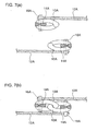
- FIG. 6 is a front view of a part of a slider fastener according to a second embodiment of the present invention showing the engagement part and the slider. FIG. 7 is a sectional view taken along line VII-VII. of FIG. 6. (a) shows a disengaged condition; (b) shows an engaged condition.
- The difference between the second embodiment and the first embodiment is that in the second embodiment, the
coil fastener elements 10A are attached along the edges of thetapes 12A as in the case of previously known fasteners. The second embodiment, however, differs from previously known fasteners in that, as shown most graphically in FIG. 7, the edges of the tapes of the second embodiment are not joined on the same plane but are joined one above the other. - In all other aspects, the construction of the second embodiment (including the
slider 20A) is the same as that of the first embodiment. As such, the same codes used in the first embodiment are used to represent the parts of the second embodiment with a character "A" added to each, and detailed explanations are dispensed with. - The first and second embodiments explained above use coils as fastener elements, but it is also possible to use rows of teeth.
- According to the present invention,
fastener elements - According to the first embodiment, the
fastener elements 10 have a special effect of not being visible from outside. Therefore, by choosing an appropriate fabric for the tape, it is possible to provide the fastener with a waterproofing feature. - The second embodiment produces a special effect in that, although the
fastener elements 10A can be seen from outside, the tapes do not overlap one above the other, so it is easier for the slider to move up and down.
Claims (7)
- A slide fastener comprising:characterised in that said fastener elements (10, 10A) protrude from the respective tapes (12, 12A) and engage with each other thereby making it possible for the pair of fastener tapes to be joined one above the other.a pair of fastener tapes (12, 12A) each having a fastener element (to, 10A) for engagement, anda slider (20, 20A) for closing and opening the fastener tapes;
- A slide fastener according to claim 1 wherein the fastener elements (10) are arranged longitudinally at locations other than the longitudinal edges of the fastener tapes (12).
- A slide fastener according to claim 1 or 2 wherein the fastener elements are coils.
- A slide fastener according to claim 1 or 2 wherein the fastener elements are rows of teeth.
- A slide fastener according to any one of claims 1 to 4, wherein the slider (20, 20A) has a guide column (22) and a top plate (24) and a bottom plate (26) provided above and below said guide column;
one end of said top plate (24) extending downward, forming a left side part (24a), while the other end extending to an open space (24b);
one end of said bottom plate (26) extending upward, forming a right side part (26a), while the other end extending to an open space (26b); and
left and right fastener-element housings (28, 30) are formed between the guide column (22) and the left and right side parts (24a, 26a). - A slide fastener according to claim 5, wherein a pull (32, 34) is established on a side part of the slider body.
- A slide fastener according to claim 6, wherein the pull (32, 34) is provided with a string (38, 38A).
Applications Claiming Priority (2)
| Application Number | Priority Date | Filing Date | Title |
|---|---|---|---|
| JP2002262313 | 2002-09-09 | ||
| JP2002262313A JP3940050B2 (en) | 2002-09-09 | 2002-09-09 | Slide fastener |
Publications (1)
| Publication Number | Publication Date |
|---|---|
| EP1396203A1 true EP1396203A1 (en) | 2004-03-10 |
Family
ID=31712355
Family Applications (1)
| Application Number | Title | Priority Date | Filing Date |
|---|---|---|---|
| EP03014295A Withdrawn EP1396203A1 (en) | 2002-09-09 | 2003-06-25 | A slide fastener |
Country Status (7)
| Country | Link |
|---|---|
| US (1) | US20040045140A1 (en) |
| EP (1) | EP1396203A1 (en) |
| JP (1) | JP3940050B2 (en) |
| KR (1) | KR20040023516A (en) |
| CN (1) | CN1481740A (en) |
| AU (1) | AU2003205028A1 (en) |
| TW (1) | TW586358U (en) |
Cited By (2)
| Publication number | Priority date | Publication date | Assignee | Title |
|---|---|---|---|---|
| WO2004100695A1 (en) * | 2003-05-19 | 2004-11-25 | Stenhaell Turo | A zip fastener and an application of a zip fastener |
| US9113665B2 (en) | 2012-02-03 | 2015-08-25 | Hts Hans Torgersen & Sonn As | Bunting bag for children |
Families Citing this family (6)
| Publication number | Priority date | Publication date | Assignee | Title |
|---|---|---|---|---|
| FI114779B (en) * | 2002-10-29 | 2004-12-31 | Turo Stenhaell | Water resistant zipper |
| US20090097782A1 (en) * | 2007-10-15 | 2009-04-16 | Illinois Tool Works Inc. | Method for producing perforated zipper for transverse direction zipper applicator |
| WO2009134438A1 (en) * | 2008-05-01 | 2009-11-05 | Kasden, Kenneth, L. | Snagless zipper |
| US8910351B2 (en) | 2010-05-05 | 2014-12-16 | Illinois Tool Works Inc. | Zipper slider assembly |
| WO2011151433A1 (en) * | 2010-06-02 | 2011-12-08 | Samsonite Ip Holdings S.A.R.L | Tamper-resistant zipper |
| CN108125330A (en) * | 2017-12-22 | 2018-06-08 | 浙江伟星实业发展股份有限公司 | A kind of slide fastener and jacket |
Citations (6)
| Publication number | Priority date | Publication date | Assignee | Title |
|---|---|---|---|---|
| BE507101A (en) * | ||||
| US3600766A (en) * | 1968-08-01 | 1971-08-24 | Herbert Alberts | Stringers for fasteners |
| US5062186A (en) * | 1987-11-09 | 1991-11-05 | The United States Of America As Represented By The United States Department Of Energy | Quick-sealing design for radiological containment |
| US5636415A (en) * | 1995-09-01 | 1997-06-10 | Illinois Tool Works Inc. | Zipper with anti-derailing ribs |
| WO2002021959A1 (en) * | 2000-09-08 | 2002-03-21 | Zip Pack Ip Ag | Ziplock for pouches and bags |
| US6394299B1 (en) * | 2000-01-11 | 2002-05-28 | The Procter & Gamble Company | Slider for opening or closing a reclosable fastener disposed in a two dimensional plane |
Family Cites Families (13)
| Publication number | Priority date | Publication date | Assignee | Title |
|---|---|---|---|---|
| USRE18612E (en) * | 1932-10-04 | Fastening device | ||
| BE407244A (en) * | 1934-01-31 | 1935-02-28 | ||
| US2077350A (en) * | 1935-12-07 | 1937-04-13 | Hookless Fastener Co | Multiple interlocking fastener |
| US2221411A (en) * | 1937-04-14 | 1940-11-12 | Talon Inc | Separable fastener |
| US2273732A (en) * | 1939-01-10 | 1942-02-17 | Talon Inc | Method of making slide fasteners |
| US2303870A (en) * | 1940-02-16 | 1942-12-01 | Wahl Brothers Inc | Slider controlled fastener |
| US2325332A (en) * | 1942-12-31 | 1943-07-27 | Marinsky Isaac | Integral separable fastener |
| US3129479A (en) * | 1962-02-02 | 1964-04-21 | Louis H Morin | Slide fastener |
| NO119295B (en) * | 1966-10-15 | 1970-04-27 | Opti Holding Ag | |
| US5596793A (en) * | 1995-02-21 | 1997-01-28 | Davis; Gary T. | Abrasion resistant slide fastener |
| US5730498A (en) * | 1996-11-12 | 1998-03-24 | Jay Medical Ltd. | Quick release closure assembly |
| JP3626372B2 (en) * | 1998-10-30 | 2005-03-09 | Ykk株式会社 | Coiled slide fastener |
| JP2001130594A (en) * | 1999-11-08 | 2001-05-15 | Showa Highpolymer Co Ltd | Plastic fastener with slider, bag including the fastener and manufacturing method of the bag |
-
2002
- 2002-09-09 JP JP2002262313A patent/JP3940050B2/en not_active Expired - Fee Related
-
2003
- 2003-06-24 TW TW092211461U patent/TW586358U/en not_active IP Right Cessation
- 2003-06-24 US US10/608,677 patent/US20040045140A1/en not_active Abandoned
- 2003-06-25 EP EP03014295A patent/EP1396203A1/en not_active Withdrawn
- 2003-06-30 AU AU2003205028A patent/AU2003205028A1/en not_active Abandoned
- 2003-07-18 CN CNA031786421A patent/CN1481740A/en active Pending
- 2003-08-29 KR KR1020030060232A patent/KR20040023516A/en not_active Application Discontinuation
Patent Citations (6)
| Publication number | Priority date | Publication date | Assignee | Title |
|---|---|---|---|---|
| BE507101A (en) * | ||||
| US3600766A (en) * | 1968-08-01 | 1971-08-24 | Herbert Alberts | Stringers for fasteners |
| US5062186A (en) * | 1987-11-09 | 1991-11-05 | The United States Of America As Represented By The United States Department Of Energy | Quick-sealing design for radiological containment |
| US5636415A (en) * | 1995-09-01 | 1997-06-10 | Illinois Tool Works Inc. | Zipper with anti-derailing ribs |
| US6394299B1 (en) * | 2000-01-11 | 2002-05-28 | The Procter & Gamble Company | Slider for opening or closing a reclosable fastener disposed in a two dimensional plane |
| WO2002021959A1 (en) * | 2000-09-08 | 2002-03-21 | Zip Pack Ip Ag | Ziplock for pouches and bags |
Cited By (2)
| Publication number | Priority date | Publication date | Assignee | Title |
|---|---|---|---|---|
| WO2004100695A1 (en) * | 2003-05-19 | 2004-11-25 | Stenhaell Turo | A zip fastener and an application of a zip fastener |
| US9113665B2 (en) | 2012-02-03 | 2015-08-25 | Hts Hans Torgersen & Sonn As | Bunting bag for children |
Also Published As
| Publication number | Publication date |
|---|---|
| JP3940050B2 (en) | 2007-07-04 |
| AU2003205028A1 (en) | 2004-03-25 |
| CN1481740A (en) | 2004-03-17 |
| JP2004097426A (en) | 2004-04-02 |
| TW586358U (en) | 2004-05-01 |
| KR20040023516A (en) | 2004-03-18 |
| US20040045140A1 (en) | 2004-03-11 |
Similar Documents
| Publication | Publication Date | Title |
|---|---|---|
| CN107920636B (en) | Reinforcing tape for slide fastener | |
| US7340806B2 (en) | Opener for slide fastener | |
| TWI355904B (en) | Slider for slide fastener | |
| US6321419B1 (en) | Brassiere fastener | |
| US20150237973A1 (en) | Slider Cover for Slide Fastener and Slide Fastener with Slide Cover | |
| US3030684A (en) | Slide fastener | |
| US4658480A (en) | Fluid-tight slide fastener | |
| EP1396203A1 (en) | A slide fastener | |
| US4819308A (en) | Zipper guard | |
| US20050263364A1 (en) | Carrying handle of luggage | |
| US5586370A (en) | Separable bottom stop assembly for slide fastener | |
| EP0567927B1 (en) | Slider for slide fastener with automatic stop means | |
| JPS6368103A (en) | Slide fastener equipped with separating and inlay jig | |
| US4635324A (en) | Slide fastener | |
| EP0704177B1 (en) | Separable bottom-end-stop assembly of synthetic resin for slide fastener | |
| US4441235A (en) | Slide fastener with bottom stop | |
| KR100910706B1 (en) | Improved zipper | |
| US2915798A (en) | Tab lock for slide-fasteners | |
| TWI662915B (en) | Zipper | |
| CN210130444U (en) | Zipper teeth chain belt | |
| KR101350647B1 (en) | Concealed zipper combined with hook | |
| CA1119390A (en) | Separable slide fastener | |
| US2818625A (en) | Tape closer for slider fasteners | |
| KR200416822Y1 (en) | The lower part of slide-fastener | |
| US2067736A (en) | Slide operative fastener structure |
Legal Events
| Date | Code | Title | Description |
|---|---|---|---|
| PUAI | Public reference made under article 153(3) epc to a published international application that has entered the european phase |
Free format text: ORIGINAL CODE: 0009012 |
|
| AK | Designated contracting states |
Kind code of ref document: A1 Designated state(s): AT BE BG CH CY CZ DE DK EE ES FI FR GB GR HU IE IT LI LU MC NL PT RO SE SI SK TR |
|
| AX | Request for extension of the european patent |
Extension state: AL LT LV MK |
|
| 17P | Request for examination filed |
Effective date: 20040831 |
|
| AKX | Designation fees paid |
Designated state(s): AT BE BG CH CY CZ DE DK EE ES FI FR GB GR HU IE IT LI LU MC NL PT RO SE SI SK TR |
|
| STAA | Information on the status of an ep patent application or granted ep patent |
Free format text: STATUS: THE APPLICATION IS DEEMED TO BE WITHDRAWN |
|
| 18D | Application deemed to be withdrawn |
Effective date: 20061005 |