EP1395201B1 - Intravascular stent - Google Patents
Intravascular stent Download PDFInfo
- Publication number
- EP1395201B1 EP1395201B1 EP02736855A EP02736855A EP1395201B1 EP 1395201 B1 EP1395201 B1 EP 1395201B1 EP 02736855 A EP02736855 A EP 02736855A EP 02736855 A EP02736855 A EP 02736855A EP 1395201 B1 EP1395201 B1 EP 1395201B1
- Authority
- EP
- European Patent Office
- Prior art keywords
- stent
- peaks
- struts
- undulating
- cylindrical ring
- Prior art date
- Legal status (The legal status is an assumption and is not a legal conclusion. Google has not performed a legal analysis and makes no representation as to the accuracy of the status listed.)
- Expired - Lifetime
Links
Images


Classifications
-
- A—HUMAN NECESSITIES
- A61—MEDICAL OR VETERINARY SCIENCE; HYGIENE
- A61F—FILTERS IMPLANTABLE INTO BLOOD VESSELS; PROSTHESES; DEVICES PROVIDING PATENCY TO, OR PREVENTING COLLAPSING OF, TUBULAR STRUCTURES OF THE BODY, e.g. STENTS; ORTHOPAEDIC, NURSING OR CONTRACEPTIVE DEVICES; FOMENTATION; TREATMENT OR PROTECTION OF EYES OR EARS; BANDAGES, DRESSINGS OR ABSORBENT PADS; FIRST-AID KITS
- A61F2/00—Filters implantable into blood vessels; Prostheses, i.e. artificial substitutes or replacements for parts of the body; Appliances for connecting them with the body; Devices providing patency to, or preventing collapsing of, tubular structures of the body, e.g. stents
- A61F2/82—Devices providing patency to, or preventing collapsing of, tubular structures of the body, e.g. stents
- A61F2/86—Stents in a form characterised by the wire-like elements; Stents in the form characterised by a net-like or mesh-like structure
- A61F2/90—Stents in a form characterised by the wire-like elements; Stents in the form characterised by a net-like or mesh-like structure characterised by a net-like or mesh-like structure
- A61F2/91—Stents in a form characterised by the wire-like elements; Stents in the form characterised by a net-like or mesh-like structure characterised by a net-like or mesh-like structure made from perforated sheet material or tubes, e.g. perforated by laser cuts or etched holes
- A61F2/915—Stents in a form characterised by the wire-like elements; Stents in the form characterised by a net-like or mesh-like structure characterised by a net-like or mesh-like structure made from perforated sheet material or tubes, e.g. perforated by laser cuts or etched holes with bands having a meander structure, adjacent bands being connected to each other
- A61F2002/91508—Stents in a form characterised by the wire-like elements; Stents in the form characterised by a net-like or mesh-like structure characterised by a net-like or mesh-like structure made from perforated sheet material or tubes, e.g. perforated by laser cuts or etched holes with bands having a meander structure, adjacent bands being connected to each other the meander having a difference in amplitude along the band
-
- A—HUMAN NECESSITIES
- A61—MEDICAL OR VETERINARY SCIENCE; HYGIENE
- A61F—FILTERS IMPLANTABLE INTO BLOOD VESSELS; PROSTHESES; DEVICES PROVIDING PATENCY TO, OR PREVENTING COLLAPSING OF, TUBULAR STRUCTURES OF THE BODY, e.g. STENTS; ORTHOPAEDIC, NURSING OR CONTRACEPTIVE DEVICES; FOMENTATION; TREATMENT OR PROTECTION OF EYES OR EARS; BANDAGES, DRESSINGS OR ABSORBENT PADS; FIRST-AID KITS
- A61F2/00—Filters implantable into blood vessels; Prostheses, i.e. artificial substitutes or replacements for parts of the body; Appliances for connecting them with the body; Devices providing patency to, or preventing collapsing of, tubular structures of the body, e.g. stents
- A61F2/82—Devices providing patency to, or preventing collapsing of, tubular structures of the body, e.g. stents
- A61F2/86—Stents in a form characterised by the wire-like elements; Stents in the form characterised by a net-like or mesh-like structure
- A61F2/90—Stents in a form characterised by the wire-like elements; Stents in the form characterised by a net-like or mesh-like structure characterised by a net-like or mesh-like structure
- A61F2/91—Stents in a form characterised by the wire-like elements; Stents in the form characterised by a net-like or mesh-like structure characterised by a net-like or mesh-like structure made from perforated sheet material or tubes, e.g. perforated by laser cuts or etched holes
- A61F2/915—Stents in a form characterised by the wire-like elements; Stents in the form characterised by a net-like or mesh-like structure characterised by a net-like or mesh-like structure made from perforated sheet material or tubes, e.g. perforated by laser cuts or etched holes with bands having a meander structure, adjacent bands being connected to each other
- A61F2002/91516—Stents in a form characterised by the wire-like elements; Stents in the form characterised by a net-like or mesh-like structure characterised by a net-like or mesh-like structure made from perforated sheet material or tubes, e.g. perforated by laser cuts or etched holes with bands having a meander structure, adjacent bands being connected to each other the meander having a change in frequency along the band
-
- A—HUMAN NECESSITIES
- A61—MEDICAL OR VETERINARY SCIENCE; HYGIENE
- A61F—FILTERS IMPLANTABLE INTO BLOOD VESSELS; PROSTHESES; DEVICES PROVIDING PATENCY TO, OR PREVENTING COLLAPSING OF, TUBULAR STRUCTURES OF THE BODY, e.g. STENTS; ORTHOPAEDIC, NURSING OR CONTRACEPTIVE DEVICES; FOMENTATION; TREATMENT OR PROTECTION OF EYES OR EARS; BANDAGES, DRESSINGS OR ABSORBENT PADS; FIRST-AID KITS
- A61F2/00—Filters implantable into blood vessels; Prostheses, i.e. artificial substitutes or replacements for parts of the body; Appliances for connecting them with the body; Devices providing patency to, or preventing collapsing of, tubular structures of the body, e.g. stents
- A61F2/82—Devices providing patency to, or preventing collapsing of, tubular structures of the body, e.g. stents
- A61F2/86—Stents in a form characterised by the wire-like elements; Stents in the form characterised by a net-like or mesh-like structure
- A61F2/90—Stents in a form characterised by the wire-like elements; Stents in the form characterised by a net-like or mesh-like structure characterised by a net-like or mesh-like structure
- A61F2/91—Stents in a form characterised by the wire-like elements; Stents in the form characterised by a net-like or mesh-like structure characterised by a net-like or mesh-like structure made from perforated sheet material or tubes, e.g. perforated by laser cuts or etched holes
- A61F2/915—Stents in a form characterised by the wire-like elements; Stents in the form characterised by a net-like or mesh-like structure characterised by a net-like or mesh-like structure made from perforated sheet material or tubes, e.g. perforated by laser cuts or etched holes with bands having a meander structure, adjacent bands being connected to each other
- A61F2002/91525—Stents in a form characterised by the wire-like elements; Stents in the form characterised by a net-like or mesh-like structure characterised by a net-like or mesh-like structure made from perforated sheet material or tubes, e.g. perforated by laser cuts or etched holes with bands having a meander structure, adjacent bands being connected to each other within the whole structure different bands showing different meander characteristics, e.g. frequency or amplitude
-
- A—HUMAN NECESSITIES
- A61—MEDICAL OR VETERINARY SCIENCE; HYGIENE
- A61F—FILTERS IMPLANTABLE INTO BLOOD VESSELS; PROSTHESES; DEVICES PROVIDING PATENCY TO, OR PREVENTING COLLAPSING OF, TUBULAR STRUCTURES OF THE BODY, e.g. STENTS; ORTHOPAEDIC, NURSING OR CONTRACEPTIVE DEVICES; FOMENTATION; TREATMENT OR PROTECTION OF EYES OR EARS; BANDAGES, DRESSINGS OR ABSORBENT PADS; FIRST-AID KITS
- A61F2/00—Filters implantable into blood vessels; Prostheses, i.e. artificial substitutes or replacements for parts of the body; Appliances for connecting them with the body; Devices providing patency to, or preventing collapsing of, tubular structures of the body, e.g. stents
- A61F2/82—Devices providing patency to, or preventing collapsing of, tubular structures of the body, e.g. stents
- A61F2/86—Stents in a form characterised by the wire-like elements; Stents in the form characterised by a net-like or mesh-like structure
- A61F2/90—Stents in a form characterised by the wire-like elements; Stents in the form characterised by a net-like or mesh-like structure characterised by a net-like or mesh-like structure
- A61F2/91—Stents in a form characterised by the wire-like elements; Stents in the form characterised by a net-like or mesh-like structure characterised by a net-like or mesh-like structure made from perforated sheet material or tubes, e.g. perforated by laser cuts or etched holes
- A61F2/915—Stents in a form characterised by the wire-like elements; Stents in the form characterised by a net-like or mesh-like structure characterised by a net-like or mesh-like structure made from perforated sheet material or tubes, e.g. perforated by laser cuts or etched holes with bands having a meander structure, adjacent bands being connected to each other
- A61F2002/91533—Stents in a form characterised by the wire-like elements; Stents in the form characterised by a net-like or mesh-like structure characterised by a net-like or mesh-like structure made from perforated sheet material or tubes, e.g. perforated by laser cuts or etched holes with bands having a meander structure, adjacent bands being connected to each other characterised by the phase between adjacent bands
-
- A—HUMAN NECESSITIES
- A61—MEDICAL OR VETERINARY SCIENCE; HYGIENE
- A61F—FILTERS IMPLANTABLE INTO BLOOD VESSELS; PROSTHESES; DEVICES PROVIDING PATENCY TO, OR PREVENTING COLLAPSING OF, TUBULAR STRUCTURES OF THE BODY, e.g. STENTS; ORTHOPAEDIC, NURSING OR CONTRACEPTIVE DEVICES; FOMENTATION; TREATMENT OR PROTECTION OF EYES OR EARS; BANDAGES, DRESSINGS OR ABSORBENT PADS; FIRST-AID KITS
- A61F2/00—Filters implantable into blood vessels; Prostheses, i.e. artificial substitutes or replacements for parts of the body; Appliances for connecting them with the body; Devices providing patency to, or preventing collapsing of, tubular structures of the body, e.g. stents
- A61F2/82—Devices providing patency to, or preventing collapsing of, tubular structures of the body, e.g. stents
- A61F2/86—Stents in a form characterised by the wire-like elements; Stents in the form characterised by a net-like or mesh-like structure
- A61F2/90—Stents in a form characterised by the wire-like elements; Stents in the form characterised by a net-like or mesh-like structure characterised by a net-like or mesh-like structure
- A61F2/91—Stents in a form characterised by the wire-like elements; Stents in the form characterised by a net-like or mesh-like structure characterised by a net-like or mesh-like structure made from perforated sheet material or tubes, e.g. perforated by laser cuts or etched holes
- A61F2/915—Stents in a form characterised by the wire-like elements; Stents in the form characterised by a net-like or mesh-like structure characterised by a net-like or mesh-like structure made from perforated sheet material or tubes, e.g. perforated by laser cuts or etched holes with bands having a meander structure, adjacent bands being connected to each other
- A61F2002/9155—Adjacent bands being connected to each other
- A61F2002/91575—Adjacent bands being connected to each other connected peak to trough
-
- A—HUMAN NECESSITIES
- A61—MEDICAL OR VETERINARY SCIENCE; HYGIENE
- A61F—FILTERS IMPLANTABLE INTO BLOOD VESSELS; PROSTHESES; DEVICES PROVIDING PATENCY TO, OR PREVENTING COLLAPSING OF, TUBULAR STRUCTURES OF THE BODY, e.g. STENTS; ORTHOPAEDIC, NURSING OR CONTRACEPTIVE DEVICES; FOMENTATION; TREATMENT OR PROTECTION OF EYES OR EARS; BANDAGES, DRESSINGS OR ABSORBENT PADS; FIRST-AID KITS
- A61F2230/00—Geometry of prostheses classified in groups A61F2/00 - A61F2/26 or A61F2/82 or A61F9/00 or A61F11/00 or subgroups thereof
- A61F2230/0002—Two-dimensional shapes, e.g. cross-sections
- A61F2230/0004—Rounded shapes, e.g. with rounded corners
- A61F2230/0013—Horseshoe-shaped, e.g. crescent-shaped, C-shaped, U-shaped
-
- A—HUMAN NECESSITIES
- A61—MEDICAL OR VETERINARY SCIENCE; HYGIENE
- A61F—FILTERS IMPLANTABLE INTO BLOOD VESSELS; PROSTHESES; DEVICES PROVIDING PATENCY TO, OR PREVENTING COLLAPSING OF, TUBULAR STRUCTURES OF THE BODY, e.g. STENTS; ORTHOPAEDIC, NURSING OR CONTRACEPTIVE DEVICES; FOMENTATION; TREATMENT OR PROTECTION OF EYES OR EARS; BANDAGES, DRESSINGS OR ABSORBENT PADS; FIRST-AID KITS
- A61F2230/00—Geometry of prostheses classified in groups A61F2/00 - A61F2/26 or A61F2/82 or A61F9/00 or A61F11/00 or subgroups thereof
- A61F2230/0002—Two-dimensional shapes, e.g. cross-sections
- A61F2230/0028—Shapes in the form of latin or greek characters
- A61F2230/0054—V-shaped
-
- Y—GENERAL TAGGING OF NEW TECHNOLOGICAL DEVELOPMENTS; GENERAL TAGGING OF CROSS-SECTIONAL TECHNOLOGIES SPANNING OVER SEVERAL SECTIONS OF THE IPC; TECHNICAL SUBJECTS COVERED BY FORMER USPC CROSS-REFERENCE ART COLLECTIONS [XRACs] AND DIGESTS
- Y10—TECHNICAL SUBJECTS COVERED BY FORMER USPC
- Y10T—TECHNICAL SUBJECTS COVERED BY FORMER US CLASSIFICATION
- Y10T29/00—Metal working
- Y10T29/53—Means to assemble or disassemble
- Y10T29/53987—Tube, sleeve or ferrule
Definitions
- the stent of the present invention has a high degree of compressibility to secure it on the catheter and provide a low profile and a high degree of flexibility making it possible to advance the stent easily through tortuous arteries, yet the stent has sufficient radial rigidity so that it can hold open an artery or other blood vessel, or tack up a dissected lining and provide adequate vessel wall coverage.
- stent 30 is made up of a plurality of cylindrical rings 40 which extend circumferentially around the stent when it is in a tubular form (see FIGS. 6C , 7C , 8B , 9B , 10B , 11B and 12 ).
- the stent has a delivery diameter 42 as shown in FIG. 12 , and an implanted diameter 44 as shown in FIG. 13 .
- Each cylindrical ring 40 has a cylindrical ring proximal end 46 and a cylindrical ring distal end 48.
- the stent is laser cut from a tube there are no discreet parts such as the described cylindrical rings and links. However, it is beneficial for identification and reference to various parts to refer to the cylindrical rings and links and other parts of the stent as follows.
- Each cylindrical ring 40 defines a cylindrical plane 50 which is a plane defined by the proximal and distal ends 46,48 of the ring and the circumferential extent as the cylindrical ring travels around the cylinder.
- Each cylindrical ring includes cylindrical outer wall surface 52 which defines the outermost surface of the stent, and cylindrical inner wall surface 53 which defines the innermost surface of the stent. Cylindrical plane 50 follows the cylindrical outer wall surface.
- the stent 30 includes a pattern that does not have a so-called W-shaped portion.
- the undulating link 54 is substantially proximal to the second peak 61, with a slight portion of the undulating link 54 being circumferentially adjacent to the second peak.
- the first peak 60 still has struts 66 that are longer than struts 68 of second peak 61 so that the stent of this design functions in substantially the same manner as that described for the other stent designs.
- the cylindrical rings 40 have the ability to flex radially as the vessel pulsates when blood pumps through it.
- the stent can flex longitudinally. The radial and longitudinal flexing of the stent reduces the likelihood that the stent will cause inj ury to the intima of a coronary artery, which also may have a tendency to reduce the likelihood of restenosis.
- the cutting process utilizing oxygen with the finely focused green beam results in a very narrow kerf (approx. 0.0127mm (0.0005 inch)) with the molten slag re-solidifying along the cut. This traps the cut out scrap of the pattern requiring further processing.
Abstract
Description
- The invention relates to intravascular stents, which are adapted to be implanted into a patient's body lumen, such as a blood vessel or coronary artery, to maintain the patency thereof. Stents are particularly useful in the treatment of atherosclerotic stenosis in arteries and blood vessels.
- Stents are generally tubular-shaped devices which function to hold open a segment of a blood vessel or other body lumen such as a coronary artery. They also are suitable for use to support and hold back a dissected arterial lining that can occlude the fluid passageway. At present, there are numerous commercial stents being marketed throughout the world. For example, the prior art stents depicted in
FIGS. 1-5 have multiplex cylindrical rings connected by one or more undulating links. While some of these stents are flexible and have the appropriate radial rigidity needed to hold open a vessel or artery, there typically is a tradeoffbetween flexibility and radial strength and the ability to tightly compress or crimp the stent onto a catheter so that it does not move relative to the catheter or dislodge prematurely prior to controlled implantation in a vessel. - For example, there is described in
WO 00/06051 - Nevertheless, that has been needed and heretofore unavailable is a stent which has a high degree of flexibility so that it can be advanced through tortuous passageways and can be readily expanded, and yet have the mechanical strength to hold open the body lumen or artery into which it is implanted and provide adequate vessel wall coverage. The present invention satisfies this need. That is, the stent of the present invention has a high degree of compressibility to secure it on the catheter and provide a low profile and a high degree of flexibility making it possible to advance the stent easily through tortuous arteries, yet the stent has sufficient radial rigidity so that it can hold open an artery or other blood vessel, or tack up a dissected lining and provide adequate vessel wall coverage.
- According to the present invention there is provided a flexible intravascular stent having the features of
claim 1. - The present invention is directed to an intravascular stent that has a pattern or configuration that permits the stent to be tightly compressed or crimped onto a catheter to provide an extremely low profile and to prevent relative movement between the stent and the catheter. The stent also is highly flexible along its longitudinal axis to facilitate delivery through tortuous body lumens, but which is stiff and stable enough radially in its expanded condition to maintain the patency of a body lumen such as an artery when the stent is implanted therein.
- The stent of the present invention - includes a plurality of cylindrical rings that are interconnected to form the stent. The stent typically is mounted on a balloon catheter if it is balloon expandable or mounted on or in a catheter without a balloon if it is self-expanding.
- Each of the cylindrical rings making up the stent have a proximal end and a distal end and a cylindrical plane defined by a cylindrical outer wall surface that extends circumferentially between the proximal end and the distal end of the cylindrical ring. Generally the cylindrical rings have a serpentine or undulating shape which includes at least one U-shaped element, and typically each ring has more than one U-shaped element. The cylindrical rings are interconnected by at least one undulating link which attaches one cylindrical ring to an adjacent cylindrical ring. The undulating links are highly flexible and allow the stent to be highly flexible along its longitudinal axis. At least some of the undulating links have a curved portion that extends transverse to the stent longitudinal axis for a predetermined distance that coincides with one of the U-shaped elements. More specifically, the curved portion extends in a transverse manner such that it would intersect with the corresponding U-shaped element, however, the corresponding U-shaped element is shorter in length than other U-shaped elements in the same ring. Thus, when the stent is compressed or crimped onto the catheter, the curved portions do not overlap or intersect with the adj acent U-shaped element since that element is shorter in length than similar U-shaped elements in the particular ring. In this manner, the stent can be compressed or crimped to a much tighter or smaller diameter onto the catheter which permits low profile delivery as well as a tight gripping force on the catheter to reduce the likelihood of movement between the stent and the catheter during delivery and prior to implanting the stent in the vessel. The undulating links may take various configurations but in general have an undulating or serpentine shape. The undulating links can include bends connected by substantially straight portions wherein the substantially straight portions are substantially perpendicular to the stent longitudinal axis.
- Not only do the undulating links that interconnect the cylindrical rings provide flexibility to the stent, but the positioning of the links also enhances the flexibility by allowing uniform flexibility when the stent is bent in any direction along its longitudinal axis. Uniform flexibility along the stent derives in part from the links of one ring being circumferentially offset from the links in an adjacent ring. Further, the cylindrical rings are configured to provide flexibility to the stent in that portions of the rings can flex or bend and tip outwardly as the stent is delivered through a tortuous vessel.
- While the cylindrical rings and undulating links generally are not separate structures, they have been conveniently referred to as rings and links for ease of identification. Further, the cylindrical rings can be thought of as comprising a series of U's, W's and Y-shaped structures in a repeating pattern. Again, while the cylindrical rings are not divided up or segmented into U's, W's and Y's, the pattern of the cylindrical rings resemble such configuration. The U's, W's and Y's promote flexibility in the stent primarily by flexing and by tipping radially outwardly as the stent is delivered through a tortuous vessel.
- The undulating links are positioned so that the curved portion of the link is outside the curved part of the W-shaped portion. Since the curved portion does not substantially expand (if at all) when the stent is expanded, it will continue to provide good vessel wall coverage even as the curved part of the W-shaped portion spreads apart as the stent is expanded. The curved portion of the link extends in a direction transverse to the stent longitudinal axis for a distance that positions it adjacent and proximal to the peak of a U-shaped element. These U-shaped elements have struts that are shorter than the struts of the other U-shaped elements in the same cylindrical ring so that as the stent is compressed the curved portion of the link does not overlap the adjacent U-shaped element.
- In one embodiment, the W-shaped portion has a first and second radius at its base where the first radius is greater than the second radius so that the first radius expands more easily than the second radius when the stent is expanded. The first radius corresponds with a second peak (U-shaped member) which is shorter than the other peaks in the ring. The second peak has shorter struts than the struts of the other peaks and as a result expands more slowly when the stent expands. Thus, faster expansion rate of the first radius of the W-shaped portion has a tendency to compensate for the slower expansion rate of the adjacent shorter second peak to provide overall uniform expansion of the stent Also, the shorter second peak can have a greater radius than the longer first peaks, again to provide different expansion rates to obtain more uniform stent expansion.
- In another embodiment, each ring has nine peaks, three each of first, second, and third peaks. The third peak has the longest struts, the second peak the shortest struts, and the first peak has intermediate length struts. In order to obtain uniform stent expansion, the radius of the peaks is inversely proportional to the strut length. The shorter second peak with the shortest struts has the biggest peak radius, the first peak has an intermediate radius, and the third peak with the longest struts has the smallest peak radius.
- The number and location of undulating links that interconnect adjacent cylindrical rings can be varied as the application requires. Since the undulating links typically do not expand when the cylindrical rings of the stent expand radially outwardly, the links are free to continue to provide flexibility and to also provide a scaffolding function to assist in holding open the artery. Importantly, the addition or removal of the undulating links has very little impact on the overall longitudinal flexibility of the stent. Each undulating link is configured so that it promotes flexibility whereas some prior art connectors actually reduce flexibility of the stent.
- The cylindrical rings of the stent are plastically deformed when expanded when the stent is made from a metal that is balloon expandable. Typically, the balloon -expandable stent is made from a stainless steel alloy or similar material.
- Similarly, the cylindrical rings of the stent expand radially outwardly when the stent is formed from superelastic alloys, such as nickel-titanium (NiTi) alloys. In the case of superelastic alloys, the stent expands upon application of a temperature change or when a stress is relieved, as in the case of a pseudoelastic phase change.
- Because of the undulating configuration of the links, the stent has a high degree of flexibility along the stent axis, which reduces the tendency of stent fishscaling. Stent fishscaling can occur when the stent is bent and portions of the stent project outward when the stent is in the unexpanded condition. The present invention undulating links reduce the likelihood of fishscaling.
- Further, because of the positioning of the links, and the fact that the links do not expand or stretch when the stent is radially expanded, the overall length of the stent is substantially the same in the unexpanded and expanded configurations. In other words, the stent will not substantially shorten upon expansion.
- The stent may be formed from a tube by laser cutting the pattern of cylindrical rings and undulating links in the tube. The stent also may be formed by laser cutting a flat metal sheet in the pattern of the cylindrical rings and links, and then rolling the pattern into the shape of the tubular stent and providing a longitudinal weld to form the stent.
-
-
FIGURE 1 is an elevational view, partially in section, of a prior art stent mounted on a rapid-exchange delivery catheter and positioned within an artery. -
FIG. 2 is an elevational view, partially in section, similar to that shown inFIG. 1 wherein the prior art stent is expanded within the artery, so that the stent embeds within the arterial wall. -
FIG. 3 is an elevational view, partially in section, showing the expanded prior art stent implanted within the artery after withdrawal of the rapid-exchange delivery catheter. -
FIG. 4 is a plan view of a flattened prior art stent which illustrates the pattern of the stent shown inFIGS. 1-3 . -
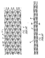
FIG. 5 is a side view of the prior art stent ofFIG. 4 in a cylindrical configuration and in an unexpanded state. -
FIG. 6A is a plan view of a flattened stent of one embodiment of the invention which illustrates the pattern of the rings and links. -
FIG. 6B is a partial plan view of the stent ofFIG. 6A which has been expanded to approximately 3.0 mm inside diameter. -
FIG. 6C is a plan view of a portion of the stent ofFIG. 6A rolled into a cylindrical configuration and tightly crimped so that the various stent struts are either in close contact or contacting each other. -
FIG. 7A is a plan view of a flattened stent of another embodiment of the invention which illustrates the pattern of the rings and links. -
FIG. 7B is a partial plan view of the stent ofFIG. 7A which has been expanded to approximately 4.0 mm inside diameter. -
FIG. 7C is a portion of the stent ofFIG. 7A that is illustrated in a cylindrical configuration and is tightly crimped or compressed. -
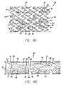
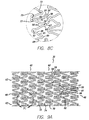
FIG. 8A is a plan view of a flattened stent of another embodiment of the invention which illustrates the pattern of the rings and links. -
FIG. 8B is a plan view of the flattened stent ofFIG. 8A where the rings and links have been crimped or tightly compressed. -
FIG. 8C is a plan view of a portion of the flattened stent ofFIG. 8A illustrating the relationship of the U-shaped member to the undulating link prior to crimping the stent. -
FIG. 9A is a plan view of a flattened stent of another embodiment of the invention which illustrates the pattern of the rings and links. -
FIG. 9B is a plan view of the flattened stent ofFIG. 9A where the rings and links have been crimped or tightly compressed. -
FIG. 9C is a portion of the flattened stent ofFIG. 9A illustrating the relationship of the shortened U-shaped member and the undulating portion of the link when the stent is in a partially crimped or compressed configuration. -
FIG. 10A is a plan view of a flattened stent of another embodiment of the invention which illustrates the pattern of the rings and links. -
FIG. 10B is a plan view of the flattened stent ofFIG. 10A in a crimped or compressed configuration. -
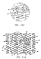
FIG. 10C is a partial plan view of the flattened stent ofFIG. 10A depicting the relationship between the shortened U-shaped member and the undulating portion of the link when the stent is partially crimped or compressed. -
FIG. 11A is a plan view of a flattened stent of another embodiment of the invention which illustrates the pattern of the rings and links. -
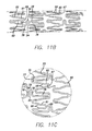
FIG. 11B is a plan view of the stent ofFIG. 11A depicting the rings and links in a crimped or compressed configuration. -
FIG. 11C is a partial plan view of the flattened stent ofFIG. 11A depicting the relationship between the shortened U-shaped member and the undulating portion of the link when the stent is partially linked or compressed. -
FIG. 12 is a plan view of the stent ofFIG. 10A rolled into a cylindrical configuration and in a crimped or compressed configuration. -
FIG. 13 is a plan view of the stent ofFIG. 10A in a cylindrical configuration and illustrating the rings and links in an expanded configuration. -
FIG. 14 is a plan view of a flattened stent of another embodiment of the invention which illustrates the pattern of rings and links. -
FIG. 15 is a plan view of a flattened stent of another embodiment of the invention which illustrates the pattern of the rings and links where each of the rings has nine peaks. -
FIG. 16 is a plan view of a flattened stent of another embodiment of the invention which illustrates the pattern of the rings and links. -
FIG. 17 is a plan view of a flattened stent depicting another design and illustrating the pattern of rings and links. -
FIG. 18 is an enlarged partial perspective view of a portion of a peak and associated struts depicting variable thickness struts. - The present invention stent improves on existing stents by providing a longitudinally flexible stent having a uniquely designed pattern and novel interconnecting members. In addition to providing longitudinal flexibility, the stent of the present invention also provides radial rigidity and a high degree of scaffolding of a vessel wall, such as a coronary artery. The design of the highly flexible interconnecting members and their placement relative to an adjacent U-shaped member provides for a tightly compressed stent onto a catheter while maintaining a high degree of flexibility during delivery.
- Turning to the drawings,
FIG. 1 depicts aprior art stent 10 mounted on aconventional catheter assembly 12 which is used to deliver the stent and implant it in a body lumen, such as a coronary artery, peripheral artery, or other vessel or lumen within the body. The catheter assembly includes acatheter shaft 13 which has aproximal end 14 and adistal end 16. The catheter assembly is configured to advance through the patient's vascular system by advancing over a guide wire by any of the well known methods of an over the wire system (not shown) or a well known rapid exchange catheter system, such as the one shown inFIG. 1 . -
Catheter assembly 12 as depicted inFIG. 1 is of the well known rapid exchange type which includes anRX port 20 where theguide wire 18 will exit the catheter. The distal end of theguide wire 18 exits the catheterdistal end 16 so that the catheter advances along the guide wire on a section of the catheter between theRX port 20 and the catheterdistal end 16. As is known in the art, the guide wire lumen which receives the guide wire is sized for receiving various diameter guide wires to suit a particular application. The stent is mounted on the expandable member 22 (balloon) and is crimped tightly thereon so that the stent and expandable member present a low profile diameter for delivery through the arteries. - As shown in
FIG. 1 , a partial cross-section of anartery 24 is shown with a small amount of plaque that has been previously treated by an angioplasty or other repair procedure.Stent 10 is used to repair a diseased or damaged arterial wall which may include theplaque 26 as shown inFIG. 1 , or a dissection, or a flap which are sometimes found in the coronary arteries, peripheral arteries and other vessels. - In a typical procedure to implant
prior art stent 10, theguide wire 18 is advanced through the patient's vascular system by well known methods so that the distal end of the guide wire is advanced past the plaque ordiseased area 26. Prior to implanting the stent, the cardiologist may wish to perform an angioplasty procedure or other procedure (i.e., atherectomy) in order to open the vessel and remodel the diseased area. Thereafter, the stentdelivery catheter assembly 12 is advanced over the guide wire so that the stent is positioned in the target area. The expandable member orballoon 22 is inflated by well known means so that it expands radially outwardly and in turn expands the stent radially outwardly until the stent is apposed to the vessel wall. The expandable member is then deflated and the catheter withdrawn from the patient's vascular system. The guide wire typically is left in the lumen for post-dilatation procedures, if any, and subsequently is withdrawn from the patient's vascular system. As depicted inFIGS. 2 and 3 , the balloon is fully inflated with the prior art stent expanded and pressed against the vessel wall, and inFIG. 3 , the implanted stent remains in the vessel after the balloon has been deflated and the catheter assembly and guide wire have been withdrawn from the patient. - The
prior art stent 10 serves to hold open the artery after the catheter is withdrawn, as illustrated byFIG. 3 . Due to the formation of the stent from an elongated tubular member, the undulating components of the stent are relatively flat in transverse cross-section, so that when the stent is expanded, it is pressed into the wall of the artery and as a result does not interfere with the blood flow through the artery. The stent is pressed into the wall of the artery and will eventually be covered with endothelial cell growth which further minimizes blood flow interference. The undulating portion of the stent provides good tacking characteristics to prevent stent movement within the artery. Furthermore, the closely spaced cylindrical elements at regular intervals provide uniform support for the wall of the artery, and consequently are well adapted to tack up and hold in place small flaps or dissections in the wall of the artery, as illustrated inFIGS. 2 and 3 . - One of the problems associated with some prior art stents such as the one shown in
FIG. 4 , is the ability to more tightly crimp or compress thestent 10 onto the balloon portion of the catheter. For example, the undulatingportion 27 of thelinks 28 of the prior art stent inFIG. 4 are positioned between twostruts 29A/29B so that as the stent is tightly crimped or compressed onto the balloon portion of the catheter, the struts can only come so close to the undulating portion before contact is made. Preferably, the undulating portion and the adjacent struts should not overlap, therefore the undulating portion of the link limits the amount of the crimping or compression of each cylindrical ring onto the balloon portion of the catheter. The present invention solves this problem and allows for a tightly compressed or crimped stent onto the catheter. - In keeping with the present invention,
FIGS. 6-16 depictstent 30 in various configurations. Referring toFIG. 6A , forexample stent 30 is shown in a flattened condition so that the pattern can be clearly viewed, even though the stent is in a cylindrical form in use, such as shown inFIG. 6C . The stent is typically formed from a tubular member, however, it can be formed from a flat sheet such as shown inFIG. 6A and rolled into a cylindrical configuration as shown inFIG. 6C . - As shown in
FIGS. 6-16 ,stent 30 is made up of a plurality ofcylindrical rings 40 which extend circumferentially around the stent when it is in a tubular form (seeFIGS. 6C ,7C ,8B ,9B ,10B ,11B and12 ). The stent has adelivery diameter 42 as shown inFIG. 12 , and an implanteddiameter 44 as shown inFIG. 13 . Eachcylindrical ring 40 has a cylindrical ringproximal end 46 and a cylindrical ringdistal end 48. Typically, since the stent is laser cut from a tube there are no discreet parts such as the described cylindrical rings and links. However, it is beneficial for identification and reference to various parts to refer to the cylindrical rings and links and other parts of the stent as follows. - Each
cylindrical ring 40 defines acylindrical plane 50 which is a plane defined by the proximal and distal ends 46,48 of the ring and the circumferential extent as the cylindrical ring travels around the cylinder. Each cylindrical ring includes cylindricalouter wall surface 52 which defines the outermost surface of the stent, and cylindricalinner wall surface 53 which defines the innermost surface of the stent.Cylindrical plane 50 follows the cylindrical outer wall surface. - In keeping with the invention, undulating
link 54 is positioned withincylindrical plane 50. The undulating links connect onecylindrical ring 30 to an adjacentcylindrical ring 30 and contribute to the overall longitudinal flexibility to the stent due to their unique construction. The flexibility of the undulating links derives in part fromcurved portion 56 connected tostraight portions 58 wherein the straight portions are substantially perpendicular to the longitudinal axis of the stent. Thus, as the stent is being delivered through a tortuous vessel, such as a coronary artery, thecurved portions 56 andstraight portions 58 of the undulating links will permit the stent to flex in the longitudinal direction which substantially enhances delivery of the stent to the target site. The number of bends and straight portions in a link can be increased or decreased from that shown, to achieve differing flexibility constructions. With the straight portions being substantially perpendicular to the stent longitudinal axis, the undulating link acts much like a hinge at the curved portion to provide flexibility. A straight link that is parallel to the stent axis typically is not flexible and does not add to the flexibility of the stent. - Referring to
FIGS. 6-16 , thestent 30 can be described more particularly as having a plurality offirst peaks 60, second peaks 61, andvalleys 62. Although the stent is not divided into separate elements, for ease of discussion references to peaks and valleys is appropriate. The number of peaks and valleys can vary in number for each ring depending upon the application. Thus, for example, if the stent is to be implanted in a coronary artery, a lesser number of peaks and valleys are required than if the stent is implanted in a peripheral artery, which has a larger diameter than a coronary artery. As can be seen for example inFIG. 6A , peaks 60,61 are inphase 63, meaning that thepeaks FIGS. 6-16 , the peaks are circumferentially offset 64 from the valleys and from the undulatinglink 54. Positioning the peaks, valleys, and undulating links in this manner, provides a stent having uniform expansion capabilities, high radial strength, a high degree of flexibility, and sufficient wall coverage to support the vessel. - In keeping with the invention, and as shown in
FIGS. 6-16 , each of the cylindrical rings has a plurality offirst peaks 60 which have first struts 66 attached to afirst apex 67. The first struts can be either curved or straight depending upon the particular application. The cylindrical rings also havesecond peaks 61 which have second struts 68 attached to asecond apex 69. Again, the second struts can be either curved or straight depending upon the particular application. Importantly, the length of the second struts 68 are shorter than the length of thefirst struts 66. As can be seen inFIGS. 6C ,7C ,8B ,9A ,9B, 9C ,10A, 10B ,10C, 11A ,11B, 11C and12 , when the stent is in a crimped condition, or a partially crimped condition, the first struts and second struts respectively will be closer to each other when the stent is compressed or crimped onto the balloon or expandable member of the catheter. The crimping or compressing process, however, also moves the undulatinglink 54 along with itscurved portion 56 closer to the second peak. In order to allow the stent to be more tightly crimped onto the balloon portion of the catheter, and to avoid overlapping between the undulating link and the second peak, the second struts 68 are shorter than the first struts 66, thus avoiding any overlapping contact between the curved portion of the undulating link and the second peak. The various stent struts, curved portions, links, and peaks and valleys may contact each other when the stent is crimped or compressed, but overlapping is an undesirable feature. - More particularly, in order to more tightly crimp or compress the cylindrical rings 40 of the
stent 30, the undulatinglink 54 is tightly crimped or compressed into contact with, or near contact with,second peak 61. As can be seen, for example, inFIG. 6C ,curved portion 56 andstraight portions 58 are in close relation tosecond peak 61 and are either in contact (not shown) or near contact withsecond apex 69. The curved portion is proximal to the second peak and the various struts in each of the rings are tightly compressed to be in contact or near contact with each other. For example, first struts 66 andsecond struts 68 as well asarm 76 of the undulating link all are in close contact, or contact with each other in order to provide a very low profile, tightly crimped stent onto the balloon portion of the catheter. Likewise, if the stent is formed of a self-expanding material such as nickel-titanium, the stent will similarly be tightly crimped and positioned within a sheath or within the catheter for delivery in the vascular system. Importantly, the curved portion and the straight portions of the undulating link are positioned relative to the second peak to allow the stent to be tightly crimped as described. - As can be seen in
FIGS. 6-16 , there are slight variations in differing embodiments of the present invention. For example, the first struts 66 and the second struts 68 of the stent depicted inFIGS. 6A-6C , are curved and have several bends along their length. In contrast, as shown inFIGS. 9A-9C , the first struts and second struts are substantially straight. Whether the various struts are substantially straight or have slight bends is a matter of choice to suit a particular application. - Referring to
FIGS. 6-16 , thestent 30 of the invention also can be described as having cylindrical rings formed ofU-shaped portions 70, Y-shapedportions 72, and W-shapedportions 74. Again, while the stent is generally laser cut from a tube and it typically has no discreet parts, for ease of identification the stent of the invention also can be referred to as having U-, Y-, and W-shaped portions. The U-shaped portions have no supporting structure attached thereto. The Y-shaped portions, at their base, or apex, havearm 78 extending therefrom which is attached to undulatinglink 54. The W portion has at its base or curve portion anarm 76 which attaches at the other end of the undulating link. The length of the arms attaching the links to the rings can vary. - Due to the intricate patterns as disclosed in
FIGS. 6-13 , the rate of expansion of the various portions of the stent, including theU-shaped portion 70, the Y-shapedportion 72, and the W-shapedportion 74, can vary. Accordingly, one aspect of the invention provides for different radii of curvature at various points so that the stent will expand evenly and uniformly. Thus,first radius 71 which corresponds withfirst peak 60 has a smaller radius of curvature than doessecond radius 73 which corresponds withsecond peak 61. Generally, the longer the struts associated with a peak, the more easily that portion of the stent will expand, so that a smaller radius is associated with peaks having longer struts. Likewise, for peaks, such assecond peak 61, which has struts 68 that are shorter than thestruts 66 offirst peak 60, has a greater radius of curvature which will expand more easily in order to compensate for the stiffer bending moments created by the shorter struts 68. - Also referring to
FIGS. 6-13 , the radius of curvature of the various portions of the W-shaped portion also varies to provide uniform stent expansion. Since thesecond peak 61 and its associatedstruts 68 have a tendency to expand more slowly as the stent is expanded, a greater radius of a curvature is provided in the adjacent part of the W-shapedportion 74. Thus,third radius 75 of the W-shapedportion 74 is greater than thefourth radius 77 in the W-shaped portion. Thethird radius 75 is adjacent tosecond peak 61 which has a tendency to expand more slowly, whilefourth radius 77 is adjacent thefirst peak 60 which has a tendency to expand more easily. By varying the radii of curvature in the W-shaped portion, the stent will expand more evenly and compensate for the varying rates of expansion of adjacent portions in a cylindrical ring. - It is also a design feature that more or fewer undulating
links 54 will be positioned between adjacent cylindrical rings 40. Further, in order to increase stent stability,straight links 80, as shown inFIG. 11A , in addition to undulatinglinks 54, connect adjacent cylindrical rings. The straight links will provide stability and assist in preventing stent foreshortening, as do the undulating links. Further, the straight links may provide more rigidity in a localized area, such as at the stent ends, such that it may be desirable to incorporate more straight links between the cylindrical rings at the stent ends than in the center of the stent. - In an alternative embodiment as shown in
FIG. 14 ,stent 30 is designed to provide good vessel wall coverage and greater expandability since eachcylindrical ring 40 has eightpeaks 90. Generally, the more peaks in a cylindrical ring that has an undulating pattern, the greater the expansion capabilities of that particular ring. Further, the stent ofFIG. 14 has a greater number oflinks 54 than in some of the other stent patterns. In this embodiment, there are four undulatinglinks 54 between adjacent rings so that the stent has uniform flexibility and maintains sufficient vessel wall coverage. - Referring to
FIG. 15 , an alternative embodiment ofstent 30 is shown in which eachcylindrical ring 40 has ninepeaks 90. As with the stent pattern depicted inFIG. 14 , the stent pattern ofFIG. 15 is capable of expanding to a greater diameter due to the greater number ofpeaks 90 and yet maintain sufficient vessel wall coverage. In this embodiment, thefirst peak 60 andsecond peak 61 are substantially the same as previously described with respect to the stent patterns depicted inFIGS. 6-13 . In this embodiment, however, athird peak 92 has a pair ofthird struts 93 and athird apex 94.Third peak 92 has third struts 93 that are longer than thefirst struts 66 and the second struts 68 of thefirst peak 60 and thesecond peak 61 respectively. As with the other embodiments, thestruts 66 of thefirst peak 60 are longer than the second struts 68 ofsecond peak 61. Further, in order to provide more uniform expansion of the stent, thethird radius 95 of thethird peak 92 is smaller than thefirst radius 71 offirst peak 60. Likewise, as previously described,first radius 71 is smaller thansecond radius 73 ofsecond peak 61. Generally speaking, the radius of curvature of the peaks are inversely proportional to the length of the struts so that the longer the struts the smaller the radius of curvature relative to shorter struts with a greater radius of curvature. As the stent expands, the peak having a greater radius of curvature will expand more easily than those having a smaller radius of curvature, thus, compensating for the length of the struts in which the peaks having shorter struts have a tendency to expand more slowly than peaks having longer struts and which have moment arms that bend more easily. - Referring to
FIG. 16 , thestent 30 is similar to the other embodiments except that the radius of curvature of all of the peaks and valleys are somewhat larger in order to make it easier to laser cut the stent pattern from a tubular member or from a flat sheet. - Turning to
FIG. 17 , in an alternative design, thestent 30 includes a pattern that does not have a so-called W-shaped portion. In this design, the undulatinglink 54 is substantially proximal to thesecond peak 61, with a slight portion of the undulatinglink 54 being circumferentially adjacent to the second peak. Thefirst peak 60 still hasstruts 66 that are longer thanstruts 68 ofsecond peak 61 so that the stent of this design functions in substantially the same manner as that described for the other stent designs. - In one aspect of the invention, after
stent 30 is implanted in a coronary artery, or other vessel, because of its novel design, the cylindrical rings 40 have the ability to flex radially as the vessel pulsates when blood pumps through it. Likewise, because of the novel and unique design of undulatinglinks 54, as the vessel moves and pulsates from the pumping blood, the stent can flex longitudinally. The radial and longitudinal flexing of the stent reduces the likelihood that the stent will cause inj ury to the intima of a coronary artery, which also may have a tendency to reduce the likelihood of restenosis. - In another aspect of the invention, the
stent 30 is formed so that the various struts of the cylindrical rings, including theU-shaped portions 70, Y-shapedportions 72, W-shapedportions 74, and the undulatinglinks 54, all can be formed so that each has a variable thickness along the stent length. For example, the undulating link, and its associatedarms second struts 68 may vary in thickness (radial thickness) along their length in order to create variable flexibility in the rings. As shown inFIG. 18 ,first peak 60 has first struts 66 that have radialthick portion 80 in the middle of the struts and radialthin portion 82 near the ends of the struts. As another example, the rings at for example the proximal end of the stent may be thicker radially than the rings in the center of the stent. A variable thickness stent that would benefit from the present invention is described and disclosed inU.S. Serial No. 09/343,962 filed June 30, 1999 second peak 61 and the undulatinglink 54. - The
stent 30 of the present invention can be mounted on a balloon catheter similar to that shown in the prior art device inFIG. 1 . The stent is tightly compressed or crimped onto the balloon portion of the catheter and remains tightly crimped onto the balloon during delivery through the patient's vascular system. When the balloon is expanded, the stent expands radially outwardly into contact with the body lumen, for example, a coronary artery. When the balloon portion of the catheter is deflated, the catheter system is withdrawn from the patient and the stent remains implanted in the artery. Similarly, if the stent of the present invention is made from a self-expanding metal alloy, such as nickel-titanium or the like, the stent may be compressed or crimped onto a catheter and a sheath (not shown) is placed over the stent to hold it in place until the stent is ready to be implanted in the patient. Such sheaths are well known in the art. Further, such a self-expanding stent may be compressed or crimped to a delivery diameter and placed within a catheter. Once the stent has been positioned within the artery, it is pushed out of the catheter or the catheter is withdrawn proximally and the stent held in place until it exits the catheter and self-expands into contact with the wall of the artery. Balloon catheters and catheters for delivering self-expanding stents are well known in the art. - The
stent 30 of the present invention can be made in many ways. One method of making the stent is to cut a thin-walled tubular member, such as stainless steel tubing to remove portions of the tubing in the desired pattern for the stent, leaving relatively untouched the portions of the metallic tubing which are to form the stent. The stent also can be made from other metal alloys such as tantalum, nickel-titanium, cobalt-chromium, titanium, shape memory and superelastic alloys, and the nobel metals such as gold or platinum. In accordance with the invention, it is preferred to cut the tubing in the desired pattern by means of a machine-controlled laser as is well known in the art. - The tubing may be made of suitable biocompatible material such as stainless steel. The stainless steel tube may be Alloy type: 316L SS, Special Chemistry per ASTM F138-92 or ASTM F 139-92 grade 2. Special Chemistry of type 316L per ASTM F138-92 or ASTM F139-92 Stainless Steel for Surgical Implants in weight percent.
Carbon (C) 0.03% max. Manganese (Mn) 2.00% max. Phosphorous (P) 0.025% max. Sulphur (S) 0.010% max. Silicon (Si) 0.75% max. Chromium (Cr) 17.00-19.00% Nickel (Ni) 13.00-15.50% Molybdenum (Mo) 2.00-3.00% Nitrogen (N) 0.10% max. Copper (Cu) 0.50% max. Iron (Fe) Balance - The stent diameter is very small, so the tubing from which it is made must necessarily also have a small diameter. Typically the stent has an outer diameter on the order of about 1.52mm (0.06 inch) in the unexpanded condition, the same outer diameter of the tubing from which it is made, and can be expanded to an outer diameter of 2.54mm (0.1 inch) or more. The wall thickness of the tubing is about 0.076mm (0.003 inch).
- The tubing is mounted in a rotatable collet fixture of a machine-controlled apparatus for positioning the tubing relative to a laser. According to machine-encoded instructions, the tubing is rotated and moved longitudinally relative to the laser which is also machine controlled. The laser selectively removes the material from the tubing by ablation and a pattern is cut into the tube. The tube is therefore cut into the discrete pattern of the finished stent.
- The process of cutting a pattern for the stent into the tubing is automated except for loading and unloading the length of tubing. In one example, a CNC-opposing collet fixture for axial rotation of the length of tubing is used in conjunction with a CNC X/Y table to move the length oftubing axially relatively to a machine-controlled laser. The entire space between collets can be patterned using the CO2 laser set-up of the foregoing example. The program for control of the apparatus is dependent on the particular configuration used and the pattern to be ablated in the coating.
- Cutting a fine structure (0.127-0.025mm (0.005 to 0.001 inch) web width) requires minimal heat input and the ability to manipulate the tube with precision. It is also necessary to support the tube yet not allow the stent structure to distort during the cutting operation. In order to successfully achieve the desired end results, the entire system must be configured very carefully. The tubes are made typically or stainless steel with an outside diameter in the range of about 1.524mm to 1.778mm (0.060 inch to 0.070 inch) and a wall thickness in the range of about 0.051mm to 0.127mm (0.002 inch to 0.005 inch). These tubes are fixtured under a laser and positioned utilizing a CNC to venerate a very intricate and precise pattern. Due to the thin wall and the small geometry of the stent pattern (about 0.089mm (0.0035 inch) typical web width), it is necessary to have very precise control of the laser, its power level, the focused spot size, and the precise positioning of the laser cutting path.
- In order to minimize the heat input into the stent structure, which prevents thermal distortion, uncontrolled burn out of the metal, and metallurgical damage due to excessive heat, and thereby produce a smooth debris free cut, a Q-switched Nd-YAG, typically available from Quantronix of Hauppauge, N.Y., that is frequency doubled to produce a green beam at 532 nanometers is utilized. Q-switching produces very short pulses (<100 nS) of high peak powers (kilowatts), low energy per pulse (≤ 3 mJ), at high pulse rates (up to 40 kHz). The frequency doubling of the beam from 1.06 microns to 0.532 microns allows the beam to be focused to a spot size that is 2 times smaller, therefore increasing the power density by a factor of 4 times. With all of these parameters, it is possible to make smooth, narrow cuts in the stainless tubes in very fine geometries without damaging the narrow struts that make up to stent structure. Hence, the described system makes it possible to adjust the laser parameters to cut narrow kerf width which will minimize the heat input into the material.
- The positioning of the tubular structure requires the use of precision CNC equipment such as that manufactured and sold by Anorad Corporation. In addition, a unique rotary mechanism has been provided that allows the computer program to be written as if the pattern were being cut from a flat sheet. This allows both circular and linear interpolation to be utilized in programming. Since the finished structure of the stent is very small, a precision drive mechanism is required that supports and drives both ends of the tubular structure as it is cut. Since both ends are driven, they must be aligned and precisely synchronized, otherwise the stent structure would twist and distort as it is being cut.
- The optical system which expands the original laser beam, delivers the beam through a viewing head and focuses the beam onto the surface of the tube, incorporates a coaxial gas jet and nozzle that helps to remove debris from the kerf and cools the region where the beam interacts with the material as the beam cuts and vaporizes the metal. It is also necessary to block the beam as it cuts through the top surface of the tube and prevent the beam, along with the molten metal and debris from the cut, from impinging on the opposite surface of the tube.
- In addition to the laser and the CNC positioning equipment, the optical delivery system includes a beam expander to increase the laser beam diameter, a circular polarizer, typically in the form of a quarter wave plate, to eliminate polarization effects in metal cutting, provisions for a spatial filter, a binocular viewing head and focusing lens, and a coaxial gas jet that provides for the introduction of a gas stream that surrounds the focused beam and is directed along the beam axis. The coaxial gas jet nozzle (0.457mm (0.018 inch) I.D.) is centered around the focused beam with approximately 0.254mm (0.010 inch) between the tip of the nozzle and the tubing. The jet is pressurized with oxygen at 137.9kPa (20 psi) and is directed at the tube with the focused laser beam exiting the tip of the nozzle (0.457mm (0.018 inch) dia.). The oxygen reacts with the metal to assist in the cutting process very similar to oxyacetylene cutting. The focused laser beam acts as an ignition source and controls the reaction of the oxygen with the metal. In this manner, it is possible to cut the material with a very fine kerf with precision. In order to prevent burning by the beam and/or molten slag on the far wall of the tube I.D., a stainless steel mandrel (approx 0.863mm (0.034 inch) dia.) is placed inside the tube and is allowed to roll on the bottom of the tube as the pattern is cut. This acts as a beam/debris block protecting the far wall I.D.
- Alternatively, this may be accomplished by inserting a second tube inside the stent tube which has an opening to trap the excess energy in the beam which is transmitted through the kerf along which collecting the debris that is ejected from the laser cut kerf. A vacuum or positive pressure can be placed in this shielding tube to remove the collection of debris.
- Another technique that could be utilized to remove the debris from the kerf and cool the surrounding material would be to use the inner beam blocking tube as an internal gas jet. By sealing one end of the tube and making a small hole in the side and placing it directly under the focused laser beam, gas pressure could be applied creating a small jet that would force the debris out of the laser cut kerf from the inside out. This would eliminate any debris from forming or collecting on the inside of the stent structure. It would place all the debris on the outside. With the use of special protective coatings, the resultant debris can be easily removed.
- In most cases, the gas utilized in the jets may be reactive or non-reactive (inert). In the case of reactive gas, oxygen or compressed air is used. Compressed air is used in this application since it offers more control of the material removed and reduces the thermal effects of the material itself. Inert gas such as argon, helium, or nitrogen can be used to eliminate any oxidation of the cut material. The result is a cut edge with no oxidation, but there is usually a tail of molten material that collects along the exit side of the gas jet that must be mechanically or chemically removed after the cutting operation.
- The cutting process utilizing oxygen with the finely focused green beam results in a very narrow kerf (approx. 0.0127mm (0.0005 inch)) with the molten slag re-solidifying along the cut. This traps the cut out scrap of the pattern requiring further processing. In order to remove the slag debris from the cut allowing the scrap to be removed from the remaining stent pattern, it is necessary to soak the cut tube in a solution of HCl for approximately 8 minutes at a temperature of approximately 55° C. Before it is soaked, the tube is placed in a bath of alcohol/water solution and ultrasonically cleaned for approximately 1 minute to remove the loose debris left from the cutting operation. After soaking, the tube is then ultrasonically cleaned in the heated HCl for 1-4 minutes depending upon the wall thickness. To prevent cracking/breaking of the struts attached to the material left at the two ends of the stent pattern due to harmonic oscillations induced by the ultrasonic cleaner, a mandrel is placed down the center of the tube during the cleaning/scrap removal process. At completion of this process, the stent structure are rinsed in water. They are now ready for electropolishing.
- The stents are preferably electrochemically polished in an acidic aqueous solution such as a solution of ELECTRO-GLO#300, sold by ELECTRO-GLO Co., Inc. in Chicago, I11., which is a mixture of sulfuric acid, carboxylic acids, phosphates, corrosion inhibitors and a biodegradable surface active agent. The bath temperature is maintained at about 43°-57°C (110°-135°F) and the current density is about 0.06 to about 0.23 amps per cm2 (0.4 to about 1.5 amps per in2). Cathode to anode area should be at least about two to one. The stents may be further treated if desired, for example by applying a biocompatible coating.
- It will be apparent that both focused laser spot size and depth of focus can be controlled by selecting beam diameter and focal length for the focusing lens. It will be apparent that increasing laser beam diameter, or reducing lens focal length, reduces spot size at the cost of depth of field.
- Direct laser cutting produces edges which are essentially perpendicular to the axis of the laser cutting beam, in contrast with chemical etching and the like which produce pattern edges which are angled. Hence, the laser cutting process essentially provides strut cross-sections, from cut-to-cut, which are square or rectangular, rather than trapezoidal. The struts have generally perpendicular edges formed by the laser cut. The resulting stent structure provides superior performance.
- Other methods of forming the stent of the present invention can be used, such as using different types of lasers; chemical etching; electric discharge machining; laser cutting a flat sheet and rolling it into a cylinder; and the like, all of which are well known in the art at this time.
- The stent of the present invention also can be made from metal alloys other than stainless steel, such as shape memory alloys. Shape memory alloys are well known and include, but are not limited to, nickel-titanium and nickel-titanium-vanadium. Any of the shape memory alloys can be formed into a tube and laser cut in order to form the pattern of the stent of the present invention. As is well known, the shape memory alloys of the stent of the present invention can include the type having superelastic or thermoelastic martensitic transformation, or display stress-induced martensite. These types of alloys are well known in the art and need not be further described here.
- Importantly, a stent formed of shape memory alloys, whether the thermoelastic or the stress-induced martensite-type, can be delivered using a balloon catheter of the type described herein, or be delivered via a catheter without a balloon or a sheath catheter.
- While the invention has been illustrated and described herein, in terms of its use as an intravascular stent, it will be apparent to those skilled in the art that the stent can be used in other body lumens. Further, particular sizes and dimensions, number of undulations or U-shaped portions per ring, materials used, and the like have been described herein and are provided as examples only. Other modifications and improvements may be made without departing from the scope of the invention.
Claims (26)
- A flexible intravascular stent for use in a body lumen, comprising:a plurality of cylindrical rings (40) aligned along a common longitudinal axis and interconnected to form the stent, each cylindrical ring (40) having a first delivery diameter (42) and a second implanted diameter (44);each cylindrical ring (40) having a plurality of first peaks (60), second peaks (61) and valleys (62), the peaks (60,61) being in phase and each of the peaks (60,61) having a height, the second peaks (61) being shorter than the first peaks (60); andat least one undulating link (54) attaching each cylindrical ring (40) to an adjacent cylindrical ring, the undulating links (54) having a curved portion (56) extending transverse to the stent longitudinal axis toward the second peak (61), the height of the second peak (61) being sized so that as the stent is compressed to the first delivery diameter (42), the curved portion (56) of the undulating link (54) is longitudinally aligned with the second peak (61),the valleys (62) being formed of U-shaped portions (70), Y-shaped portions (72) and W-shaped portions (74), the Y-shaped portions (72), at their base, having an arm (78) extending therefrom which is attached to an undulating link (54) and a W-shaped portion (74) of an adjacent cylindrical ring having at its base an arm (76) which attaches at the other end of the undulating link (54) such that the peaks (60,61) are circumferentially offset from the valleys (62) and from the undulating link (54).
- The stent of claim 1, wherein at least one undulating link (54) comprises at least one curved portion (56) connected to a substantially straight portion (58), the substantially straight portion (58) being substantially perpendicular to the stent longitudinal axis.
- The stent of claim 2, wherein the substantially straight portion (58) of the at least one undulating link (54) is perpendicular to the stent longitudinal axis when the stent is in the first delivery diameter (42) configuration.
- The stent of claim 2, wherein the substantially straight portion (58) of the at least one undulating link (54) is perpendicular to the stent longitudinal axis when the stent is in the second implanted diameter (44) configuration.
- The stent of claim 1, wherein at least one of the undulating links (54) comprise a plurality of curved portions (56).
- The stent of claim 1, wherein the first peaks (60) of each cylindrical ring (40) are in phase with the first peaks (60) of an adjacent cylindrical ring.
- The stent of claim 1, wherein the undulating links (54) are configured to provide flexibility to the stent.
- The stent of claim 1, wherein the cylindrical rings (40) are configured to provide flexibility to the stent.
- The stent of claim 1, wherein the stent is formed from a tube.
- The stent of claim 1, wherein the stent is formed from a flat sheet.
- The stent of claim 1, wherein the stent is formed from a metal alloy.
- The stent of claim 11, wherein the stent is formed from any of the group of metal alloys. consisting of stainless steel, tantalum, nickel-titanium, cobalt-chromium and titanium.
- The stent of claim 1, wherein the stent is formed from a shape memory alloy.
- The stent of claim 13, wherein the stent is formed from the group of shape memory alloys consisting of nickel-titanium and nickel-titanium-vanadium.
- The stent of claim 1, wherein the stent is formed from a superelastic or pseudoelastic metal alloy.
- The stent of claim 15, wherein the stent is formed from the group of superelastic or pseudoelastic metal alloys consisting of nickel-titanium and nickel-titanium-vanadium.
- The stent of claim 1, wherein at least a portion of the stent has a variable thickness configuration.
- The stent of claim 1, wherein at least a portion of the first peaks (60) has a variable thickness configuration.
- The stent of claim 1, wherein at least a portion of the second peaks (61) has a variable thickness configuration.
- The stent of claim 1, wherein at least a portion of the undulating links (54) has a variable thickness configuration.
- The stent of claim 1, wherein at least a portion of the cylindrical ring (40) has a variable thickness configuration.
- The stent of claim 1, wherein the first peaks (60) have a first radius (71) and the second peaks (61) have a second radius (73), the second radius (73) being greater than the first radius (71).
- The stent of claim 1, wherein each cylindrical ring (40) has a plurality of third peaks (92), each of the third peaks (92) having a height, the third peaks (92) being longer than the first peaks (60) and the second peaks (61).
- The stent of claim 1, wherein each of the first peaks (60) has a pair of first struts (66) and each of the second peaks (61) has a pair of second struts (68), the first struts (66) being longer than the second struts (68).
- The stent of claim 1, wherein each cylindrical ring (40) has a plurality of third peaks (92) and a pair of third struts (93) associated with the third peaks (92).
- The stent of claim 25, wherein the first peaks (60) have a pair of first struts (66), the second peaks (61) have a pair of second struts (68), the third struts (93) being longer than the first struts (66), and the first struts (66) being longer than the second struts (68).
Priority Applications (1)
| Application Number | Priority Date | Filing Date | Title |
|---|---|---|---|
| EP11173356.4A EP2374431B1 (en) | 2001-06-11 | 2002-05-16 | Intravascular stent |
Applications Claiming Priority (3)
| Application Number | Priority Date | Filing Date | Title |
|---|---|---|---|
| US879263 | 2001-06-11 | ||
| US09/879,263 US6629994B2 (en) | 2001-06-11 | 2001-06-11 | Intravascular stent |
| PCT/US2002/015349 WO2002100298A1 (en) | 2001-06-11 | 2002-05-16 | Intravascular stent |
Related Child Applications (2)
| Application Number | Title | Priority Date | Filing Date |
|---|---|---|---|
| EP11173356.4A Division EP2374431B1 (en) | 2001-06-11 | 2002-05-16 | Intravascular stent |
| EP11173356.4 Division-Into | 2011-07-08 |
Publications (2)
| Publication Number | Publication Date |
|---|---|
| EP1395201A1 EP1395201A1 (en) | 2004-03-10 |
| EP1395201B1 true EP1395201B1 (en) | 2011-10-19 |
Family
ID=25373772
Family Applications (2)
| Application Number | Title | Priority Date | Filing Date |
|---|---|---|---|
| EP02736855A Expired - Lifetime EP1395201B1 (en) | 2001-06-11 | 2002-05-16 | Intravascular stent |
| EP11173356.4A Expired - Fee Related EP2374431B1 (en) | 2001-06-11 | 2002-05-16 | Intravascular stent |
Family Applications After (1)
| Application Number | Title | Priority Date | Filing Date |
|---|---|---|---|
| EP11173356.4A Expired - Fee Related EP2374431B1 (en) | 2001-06-11 | 2002-05-16 | Intravascular stent |
Country Status (4)
| Country | Link |
|---|---|
| US (2) | US6629994B2 (en) |
| EP (2) | EP1395201B1 (en) |
| JP (1) | JP4463546B2 (en) |
| WO (1) | WO2002100298A1 (en) |
Families Citing this family (150)
| Publication number | Priority date | Publication date | Assignee | Title |
|---|---|---|---|---|
| US6325826B1 (en) * | 1998-01-14 | 2001-12-04 | Advanced Stent Technologies, Inc. | Extendible stent apparatus |
| US6241762B1 (en) | 1998-03-30 | 2001-06-05 | Conor Medsystems, Inc. | Expandable medical device with ductile hinges |
| US7887578B2 (en) | 1998-09-05 | 2011-02-15 | Abbott Laboratories Vascular Enterprises Limited | Stent having an expandable web structure |
| US6755856B2 (en) | 1998-09-05 | 2004-06-29 | Abbott Laboratories Vascular Enterprises Limited | Methods and apparatus for stenting comprising enhanced embolic protection, coupled with improved protection against restenosis and thrombus formation |
| US6682554B2 (en) | 1998-09-05 | 2004-01-27 | Jomed Gmbh | Methods and apparatus for a stent having an expandable web structure |
| US7815763B2 (en) * | 2001-09-28 | 2010-10-19 | Abbott Laboratories Vascular Enterprises Limited | Porous membranes for medical implants and methods of manufacture |
| GB0020491D0 (en) | 2000-08-18 | 2000-10-11 | Angiomed Ag | Stent with attached element and method of making such a stent |
| KR100532631B1 (en) * | 2001-01-15 | 2005-12-01 | 데루모 가부시끼 가이샤 | Stent |
| US6800090B2 (en) | 2001-05-14 | 2004-10-05 | Cardiac Dimensions, Inc. | Mitral valve therapy device, system and method |
| US6939373B2 (en) * | 2003-08-20 | 2005-09-06 | Advanced Cardiovascular Systems, Inc. | Intravascular stent |
| US7520892B1 (en) * | 2001-06-28 | 2009-04-21 | Advanced Cardiovascular Systems, Inc. | Low profile stent with flexible link |
| US7842083B2 (en) | 2001-08-20 | 2010-11-30 | Innovational Holdings, Llc. | Expandable medical device with improved spatial distribution |
| US6824562B2 (en) | 2002-05-08 | 2004-11-30 | Cardiac Dimensions, Inc. | Body lumen device anchor, device and assembly |
| US7635387B2 (en) | 2001-11-01 | 2009-12-22 | Cardiac Dimensions, Inc. | Adjustable height focal tissue deflector |
| US7311729B2 (en) | 2002-01-30 | 2007-12-25 | Cardiac Dimensions, Inc. | Device and method for modifying the shape of a body organ |
| US6949122B2 (en) | 2001-11-01 | 2005-09-27 | Cardiac Dimensions, Inc. | Focused compression mitral valve device and method |
| US6793673B2 (en) | 2002-12-26 | 2004-09-21 | Cardiac Dimensions, Inc. | System and method to effect mitral valve annulus of a heart |
| US7179282B2 (en) | 2001-12-05 | 2007-02-20 | Cardiac Dimensions, Inc. | Device and method for modifying the shape of a body organ |
| US6976995B2 (en) | 2002-01-30 | 2005-12-20 | Cardiac Dimensions, Inc. | Fixed length anchor and pull mitral valve device and method |
| US6991646B2 (en) * | 2001-12-18 | 2006-01-31 | Linvatec Biomaterials, Inc. | Method and apparatus for delivering a stent into a body lumen |
| US6797001B2 (en) | 2002-03-11 | 2004-09-28 | Cardiac Dimensions, Inc. | Device, assembly and method for mitral valve repair |
| EP2289467A1 (en) | 2002-05-08 | 2011-03-02 | Cardiac Dimensions, Inc. | Device for modifying the shape of a body organ |
| US7025777B2 (en) * | 2002-07-31 | 2006-04-11 | Unison Therapeutics, Inc. | Flexible and conformable stent and method of forming same |
| US6786922B2 (en) * | 2002-10-08 | 2004-09-07 | Cook Incorporated | Stent with ring architecture and axially displaced connector segments |
| US7223283B2 (en) * | 2002-10-09 | 2007-05-29 | Boston Scientific Scimed, Inc. | Stent with improved flexibility |
| US20040093056A1 (en) | 2002-10-26 | 2004-05-13 | Johnson Lianw M. | Medical appliance delivery apparatus and method of use |
| US7959671B2 (en) * | 2002-11-05 | 2011-06-14 | Merit Medical Systems, Inc. | Differential covering and coating methods |
| US7637942B2 (en) * | 2002-11-05 | 2009-12-29 | Merit Medical Systems, Inc. | Coated stent with geometry determinated functionality and method of making the same |
| US7875068B2 (en) * | 2002-11-05 | 2011-01-25 | Merit Medical Systems, Inc. | Removable biliary stent |
| US7527644B2 (en) * | 2002-11-05 | 2009-05-05 | Alveolus Inc. | Stent with geometry determinated functionality and method of making the same |
| US7144422B1 (en) * | 2002-11-13 | 2006-12-05 | Advanced Cardiovascular Systems, Inc. | Drug-eluting stent and methods of making the same |
| US7435255B1 (en) | 2002-11-13 | 2008-10-14 | Advnaced Cardiovascular Systems, Inc. | Drug-eluting stent and methods of making |
| US7316708B2 (en) | 2002-12-05 | 2008-01-08 | Cardiac Dimensions, Inc. | Medical device delivery system |
| US7837729B2 (en) | 2002-12-05 | 2010-11-23 | Cardiac Dimensions, Inc. | Percutaneous mitral valve annuloplasty delivery system |
| US7105018B1 (en) * | 2002-12-30 | 2006-09-12 | Advanced Cardiovascular Systems, Inc. | Drug-eluting stent cover and method of use |
| DE10300475B4 (en) * | 2003-01-09 | 2008-11-13 | Alveolus Inc. | Stent with a tubular expandable support device |
| US7314485B2 (en) | 2003-02-03 | 2008-01-01 | Cardiac Dimensions, Inc. | Mitral valve device using conditioned shape memory alloy |
| US7942920B2 (en) | 2003-02-25 | 2011-05-17 | Cordis Corporation | Stent with nested fingers for enhanced vessel coverage |
| US7637934B2 (en) | 2003-03-31 | 2009-12-29 | Merit Medical Systems, Inc. | Medical appliance optical delivery and deployment apparatus and method |
| US20040215311A1 (en) * | 2003-04-28 | 2004-10-28 | Kantor John D. | Method and system for improving stent retention using stent openings |
| US7604660B2 (en) | 2003-05-01 | 2009-10-20 | Merit Medical Systems, Inc. | Bifurcated medical appliance delivery apparatus and method |
| US20040220654A1 (en) | 2003-05-02 | 2004-11-04 | Cardiac Dimensions, Inc. | Device and method for modifying the shape of a body organ |
| US20040220657A1 (en) * | 2003-05-02 | 2004-11-04 | Cardiac Dimensions, Inc., A Washington Corporation | Tissue shaping device with conformable anchors |
| DE10323628A1 (en) * | 2003-05-20 | 2004-12-30 | Biotronik Ag | Stents made of a material with low elongation at break |
| US7351259B2 (en) | 2003-06-05 | 2008-04-01 | Cardiac Dimensions, Inc. | Device, system and method to affect the mitral valve annulus of a heart |
| US7887582B2 (en) | 2003-06-05 | 2011-02-15 | Cardiac Dimensions, Inc. | Device and method for modifying the shape of a body organ |
| US7959665B2 (en) * | 2003-07-31 | 2011-06-14 | Abbott Cardiovascular Systems Inc. | Intravascular stent with inverted end rings |
| US7757691B2 (en) * | 2003-08-07 | 2010-07-20 | Merit Medical Systems, Inc. | Therapeutic medical appliance delivery and method of use |
| AU2004277962A1 (en) * | 2003-09-30 | 2005-04-14 | Alveolus Inc. | Removable stent |
| US7252746B2 (en) * | 2003-11-12 | 2007-08-07 | Cook Incorporated | Electropolishing apparatus and method for medical implants |
| US7090694B1 (en) * | 2003-11-19 | 2006-08-15 | Advanced Cardiovascular Systems, Inc. | Portal design for stent for treating bifurcated vessels |
| CA2546809A1 (en) * | 2003-11-20 | 2005-11-24 | Eric K. Mangiardi | Differential covering and coating methods |
| US9526616B2 (en) | 2003-12-19 | 2016-12-27 | Cardiac Dimensions Pty. Ltd. | Mitral valve annuloplasty device with twisted anchor |
| US7837728B2 (en) | 2003-12-19 | 2010-11-23 | Cardiac Dimensions, Inc. | Reduced length tissue shaping device |
| US7794496B2 (en) | 2003-12-19 | 2010-09-14 | Cardiac Dimensions, Inc. | Tissue shaping device with integral connector and crimp |
| US7763011B2 (en) * | 2003-12-22 | 2010-07-27 | Boston Scientific Scimed, Inc. | Variable density braid stent |
| US8454676B1 (en) * | 2004-01-20 | 2013-06-04 | Advanced Cardiovascular Systems, Inc. | Transition matching stent |
| US20070293927A1 (en) * | 2004-02-17 | 2007-12-20 | The Children's Hospital Of Philadelphia | Gene and Cell Delivery Self Expanding Polymer Stents |
| DE102004012981B4 (en) * | 2004-03-16 | 2009-01-02 | Alveolus Inc. | stent |
| DE102004012837B4 (en) * | 2004-03-16 | 2006-09-14 | Admedes Schuessler Gmbh | Stent having a web structure and method of making the same |
| US8858616B2 (en) | 2004-03-16 | 2014-10-14 | Admedes Schuessler Gmbh | Stent having a bridge structure |
| US7578840B2 (en) * | 2004-03-31 | 2009-08-25 | Cook Incorporated | Stent with reduced profile |
| US7763064B2 (en) * | 2004-06-08 | 2010-07-27 | Medinol, Ltd. | Stent having struts with reverse direction curvature |
| AU2005260732B2 (en) * | 2004-06-30 | 2011-08-25 | Cardinal Health 529, Llc | Intraluminal medical device having asymetrical members |
| CA2572265C (en) * | 2004-06-30 | 2015-10-27 | Cordis Corporation | Stent having asymmetrical members of unequal length |
| US8747879B2 (en) | 2006-04-28 | 2014-06-10 | Advanced Cardiovascular Systems, Inc. | Method of fabricating an implantable medical device to reduce chance of late inflammatory response |
| US7971333B2 (en) | 2006-05-30 | 2011-07-05 | Advanced Cardiovascular Systems, Inc. | Manufacturing process for polymetric stents |
| US20140107761A1 (en) | 2004-07-26 | 2014-04-17 | Abbott Cardiovascular Systems Inc. | Biodegradable stent with enhanced fracture toughness |
| US7731890B2 (en) | 2006-06-15 | 2010-06-08 | Advanced Cardiovascular Systems, Inc. | Methods of fabricating stents with enhanced fracture toughness |
| US7887579B2 (en) | 2004-09-29 | 2011-02-15 | Merit Medical Systems, Inc. | Active stent |
| US7344560B2 (en) * | 2004-10-08 | 2008-03-18 | Boston Scientific Scimed, Inc. | Medical devices and methods of making the same |
| CA2595580A1 (en) | 2005-01-20 | 2006-07-27 | Cardiac Dimensions, Inc. | Tissue shaping device |
| US7540995B2 (en) | 2005-03-03 | 2009-06-02 | Icon Medical Corp. | Process for forming an improved metal alloy stent |
| US9107899B2 (en) | 2005-03-03 | 2015-08-18 | Icon Medical Corporation | Metal alloys for medical devices |
| US20060259127A1 (en) * | 2005-05-10 | 2006-11-16 | Deborah Tolomeo | Apparatus and method for anchoring endoluminal prostheses in tortuous geometries |
| EP1885288B1 (en) * | 2005-05-13 | 2015-03-18 | Merit Medical Systems, Inc. | Drainage stent and associated method |
| US7503932B2 (en) | 2006-04-11 | 2009-03-17 | Cardiac Dimensions, Inc. | Mitral valve annuloplasty device with vena cava anchor |
| GB0609841D0 (en) | 2006-05-17 | 2006-06-28 | Angiomed Ag | Bend-capable tubular prosthesis |
| GB0609911D0 (en) | 2006-05-18 | 2006-06-28 | Angiomed Ag | Bend-capable stent prosthesis |
| WO2008008291A2 (en) * | 2006-07-13 | 2008-01-17 | Icon Medical Corp. | Stent |
| US11285005B2 (en) | 2006-07-17 | 2022-03-29 | Cardiac Dimensions Pty. Ltd. | Mitral valve annuloplasty device with twisted anchor |
| US8882826B2 (en) * | 2006-08-22 | 2014-11-11 | Abbott Cardiovascular Systems Inc. | Intravascular stent |
| US8834554B2 (en) | 2006-08-22 | 2014-09-16 | Abbott Cardiovascular Systems Inc. | Intravascular stent |
| DE602007014061D1 (en) | 2006-08-22 | 2011-06-01 | Abbott Cardiovascular Systems | INTRAVASCULAR STENT |
| GB0616999D0 (en) * | 2006-08-29 | 2006-10-04 | Angiomed Ag | Annular mesh |
| US8500793B2 (en) * | 2006-09-07 | 2013-08-06 | C. R. Bard, Inc. | Helical implant having different ends |
| AU2007299659B2 (en) * | 2006-09-21 | 2011-09-29 | Mico Innovations, Llc | A specially configured and surface modified medical device with certain design features that utilize the intrinsic properties of tungsten, zirconium, tantalum and/or niobium |
| JP4871692B2 (en) * | 2006-09-29 | 2012-02-08 | テルモ株式会社 | In vivo indwelling stent and biological organ dilator |
| US8778009B2 (en) * | 2006-10-06 | 2014-07-15 | Abbott Cardiovascular Systems Inc. | Intravascular stent |
| US7780798B2 (en) | 2006-10-13 | 2010-08-24 | Boston Scientific Scimed, Inc. | Medical devices including hardened alloys |
| GB0622465D0 (en) * | 2006-11-10 | 2006-12-20 | Angiomed Ag | Stent |
| GB0624419D0 (en) * | 2006-12-06 | 2007-01-17 | Angiomed Ag | Stenting ring with marker |
| US8974514B2 (en) * | 2007-03-13 | 2015-03-10 | Abbott Cardiovascular Systems Inc. | Intravascular stent with integrated link and ring strut |
| GB0706499D0 (en) | 2007-04-03 | 2007-05-09 | Angiomed Ag | Bendable stent |
| US8388673B2 (en) * | 2008-05-02 | 2013-03-05 | Abbott Cardiovascular Systems Inc. | Polymeric stent |
| US8303644B2 (en) | 2007-05-04 | 2012-11-06 | Abbott Cardiovascular Systems Inc. | Stents with high radial strength and methods of manufacturing same |
| US8016874B2 (en) | 2007-05-23 | 2011-09-13 | Abbott Laboratories Vascular Enterprises Limited | Flexible stent with elevated scaffolding properties |
| US8128679B2 (en) | 2007-05-23 | 2012-03-06 | Abbott Laboratories Vascular Enterprises Limited | Flexible stent with torque-absorbing connectors |
| ES2603282T3 (en) | 2007-06-22 | 2017-02-24 | C.R. Bard, Inc. | Flexible stent with articulated connectors |
| GB0717481D0 (en) | 2007-09-07 | 2007-10-17 | Angiomed Ag | Self-expansible stent with radiopaque markers |
| US10166127B2 (en) | 2007-12-12 | 2019-01-01 | Intact Vascular, Inc. | Endoluminal device and method |
| US7896911B2 (en) | 2007-12-12 | 2011-03-01 | Innovasc Llc | Device and method for tacking plaque to blood vessel wall |
| US8128677B2 (en) | 2007-12-12 | 2012-03-06 | Intact Vascular LLC | Device and method for tacking plaque to a blood vessel wall |
| US10022250B2 (en) | 2007-12-12 | 2018-07-17 | Intact Vascular, Inc. | Deployment device for placement of multiple intraluminal surgical staples |
| US7972373B2 (en) * | 2007-12-19 | 2011-07-05 | Advanced Technologies And Regenerative Medicine, Llc | Balloon expandable bioabsorbable stent with a single stress concentration region interconnecting adjacent struts |
| US8337544B2 (en) | 2007-12-20 | 2012-12-25 | Abbott Laboratories Vascular Enterprises Limited | Endoprosthesis having flexible connectors |
| US7850726B2 (en) | 2007-12-20 | 2010-12-14 | Abbott Laboratories Vascular Enterprises Limited | Endoprosthesis having struts linked by foot extensions |
| US8920488B2 (en) * | 2007-12-20 | 2014-12-30 | Abbott Laboratories Vascular Enterprises Limited | Endoprosthesis having a stable architecture |
| GB2475494B (en) * | 2009-11-18 | 2011-11-23 | Cook William Europ | Stent graft and introducer assembly |
| US8574284B2 (en) * | 2007-12-26 | 2013-11-05 | Cook Medical Technologies Llc | Low profile non-symmetrical bare alignment stents with graft |
| US8992593B2 (en) * | 2007-12-26 | 2015-03-31 | Cook Medical Technologies Llc | Apparatus and methods for deployment of a modular stent-graft system |
| GB2476451A (en) * | 2009-11-19 | 2011-06-29 | Cook William Europ | Stent Graft |
| US8728145B2 (en) | 2008-12-11 | 2014-05-20 | Cook Medical Technologies Llc | Low profile non-symmetrical stents and stent-grafts |
| US9180030B2 (en) | 2007-12-26 | 2015-11-10 | Cook Medical Technologies Llc | Low profile non-symmetrical stent |
| US9226813B2 (en) | 2007-12-26 | 2016-01-05 | Cook Medical Technologies Llc | Low profile non-symmetrical stent |
| US8006594B2 (en) | 2008-08-11 | 2011-08-30 | Cardiac Dimensions, Inc. | Catheter cutting tool |
| RU2566225C2 (en) * | 2009-02-09 | 2015-10-20 | ЭВИЗИО МЕДИКАЛ ДЕВАЙСИЗ ЮЭлСи | Stent |
| GB2468861B (en) * | 2009-03-23 | 2011-05-18 | Cook William Europ | Conformable stent structure and method of making same |
| US9757263B2 (en) * | 2009-11-18 | 2017-09-12 | Cook Medical Technologies Llc | Stent graft and introducer assembly |
| US8568471B2 (en) | 2010-01-30 | 2013-10-29 | Abbott Cardiovascular Systems Inc. | Crush recoverable polymer scaffolds |
| US8808353B2 (en) | 2010-01-30 | 2014-08-19 | Abbott Cardiovascular Systems Inc. | Crush recoverable polymer scaffolds having a low crossing profile |
| US8398916B2 (en) | 2010-03-04 | 2013-03-19 | Icon Medical Corp. | Method for forming a tubular medical device |
| US8882824B2 (en) * | 2010-04-20 | 2014-11-11 | Cg Bio Co., Ltd. | Expanding vascular stent |
| US8888841B2 (en) | 2010-06-21 | 2014-11-18 | Zorion Medical, Inc. | Bioabsorbable implants |
| US8556511B2 (en) | 2010-09-08 | 2013-10-15 | Abbott Cardiovascular Systems, Inc. | Fluid bearing to support stent tubing during laser cutting |
| US8986369B2 (en) | 2010-12-01 | 2015-03-24 | Zorion Medical, Inc. | Magnesium-based absorbable implants |
| JP2014508559A (en) | 2010-12-30 | 2014-04-10 | ボストン サイエンティフィック サイムド,インコーポレイテッド | Multi-stage open stent design |
| US8790388B2 (en) | 2011-03-03 | 2014-07-29 | Boston Scientific Scimed, Inc. | Stent with reduced profile |
| WO2012118526A1 (en) | 2011-03-03 | 2012-09-07 | Boston Scientific Scimed, Inc. | Low strain high strength stent |
| US8747649B2 (en) | 2011-05-13 | 2014-06-10 | Abbott Cardiovascular Systems Inc. | Electrochemical formation of foil-shaped stent struts |
| US10390977B2 (en) | 2011-06-03 | 2019-08-27 | Intact Vascular, Inc. | Endovascular implant |
| US8726483B2 (en) | 2011-07-29 | 2014-05-20 | Abbott Cardiovascular Systems Inc. | Methods for uniform crimping and deployment of a polymer scaffold |
| BR112014028242B1 (en) | 2012-05-14 | 2021-04-13 | C.R. Bard, Inc | INTRALUMINAL PROSTHESIS |
| USD723165S1 (en) | 2013-03-12 | 2015-02-24 | C. R. Bard, Inc. | Stent |
| US9259335B2 (en) * | 2013-03-15 | 2016-02-16 | Covidien Lp | Stent |
| US9180031B2 (en) | 2013-03-15 | 2015-11-10 | Covidien Lp | Stent with varying radius between struts |
| AU2014284216B2 (en) | 2013-06-21 | 2017-10-05 | Boston Scientific Scimed, Inc. | Stent with deflecting connector |
| BR112016030273A8 (en) | 2014-06-24 | 2021-05-18 | Icon Medical Corp | medical device and method of forming said device |
| CA2962623C (en) * | 2014-10-22 | 2019-07-16 | Boston Scientific Scimed, Inc. | Stent with flexible hinge |
| US9433520B2 (en) | 2015-01-29 | 2016-09-06 | Intact Vascular, Inc. | Delivery device and method of delivery |
| US9375336B1 (en) | 2015-01-29 | 2016-06-28 | Intact Vascular, Inc. | Delivery device and method of delivery |
| US10993824B2 (en) | 2016-01-01 | 2021-05-04 | Intact Vascular, Inc. | Delivery device and method of delivery |
| US11766506B2 (en) | 2016-03-04 | 2023-09-26 | Mirus Llc | Stent device for spinal fusion |
| US20190175326A1 (en) * | 2016-08-25 | 2019-06-13 | Mico Innovations, Llc | Neurovascular Stent |
| US10390953B2 (en) | 2017-03-08 | 2019-08-27 | Cardiac Dimensions Pty. Ltd. | Methods and devices for reducing paravalvular leakage |
| US10463514B2 (en) | 2017-06-27 | 2019-11-05 | Abbott Cardiovascular Systems Inc. | Intravascular stent having high fatigue performance |
| US10238513B2 (en) | 2017-07-19 | 2019-03-26 | Abbott Cardiovascular Systems Inc. | Intravascular stent |
| US11660218B2 (en) | 2017-07-26 | 2023-05-30 | Intact Vascular, Inc. | Delivery device and method of delivery |
| US11517457B2 (en) * | 2019-07-03 | 2022-12-06 | Abbott Cardiovascular Systems Inc. | Intravascular stent |
| WO2022132571A1 (en) | 2020-12-14 | 2022-06-23 | Cardiac Dimensions Pty. Ltd. | Modular pre-loaded medical implants and delivery systems |
Citations (1)
| Publication number | Priority date | Publication date | Assignee | Title |
|---|---|---|---|---|
| WO2000006051A1 (en) * | 1998-07-28 | 2000-02-10 | Advanced Cardiovascular Systems, Inc. | Improved stent configuration |
Family Cites Families (115)
| Publication number | Priority date | Publication date | Assignee | Title |
|---|---|---|---|---|
| DE3136725A1 (en) | 1981-09-16 | 1983-03-31 | Robert Bosch Gmbh, 7000 Stuttgart | METHOD AND DEVICE FOR CONTROLLING A LOWER GEARBOX |
| US4580568A (en) | 1984-10-01 | 1986-04-08 | Cook, Incorporated | Percutaneous endovascular stent and method for insertion thereof |
| US5102417A (en) | 1985-11-07 | 1992-04-07 | Expandable Grafts Partnership | Expandable intraluminal graft, and method and apparatus for implanting an expandable intraluminal graft |
| US4931615A (en) | 1988-12-02 | 1990-06-05 | General Electric Company | Apparatus for machining intricate feature cuts in thin walled tubular parts |
| US5292331A (en) | 1989-08-24 | 1994-03-08 | Applied Vascular Engineering, Inc. | Endovascular support device |
| US5674278A (en) | 1989-08-24 | 1997-10-07 | Arterial Vascular Engineering, Inc. | Endovascular support device |
| CA2026604A1 (en) | 1989-10-02 | 1991-04-03 | Rodney G. Wolff | Articulated stent |
| CA2079417C (en) | 1991-10-28 | 2003-01-07 | Lilip Lau | Expandable stents and method of making same |
| US5342387A (en) | 1992-06-18 | 1994-08-30 | American Biomed, Inc. | Artificial support for a blood vessel |
| ES2157977T3 (en) | 1993-07-23 | 2001-09-01 | Cook Inc | FLEXIBLE PROBE THAT HAS A CONFORMED CONFIGURATION FROM A MATERIAL SHEET. |
| EP0714270B1 (en) | 1993-08-18 | 2002-09-04 | W.L. Gore & Associates, Inc. | A tubular intraluminally insertable graft |
| DE69419877T2 (en) | 1993-11-04 | 1999-12-16 | Bard Inc C R | Fixed vascular prosthesis |
| US6051020A (en) | 1994-02-09 | 2000-04-18 | Boston Scientific Technology, Inc. | Bifurcated endoluminal prosthesis |
| US5643312A (en) | 1994-02-25 | 1997-07-01 | Fischell Robert | Stent having a multiplicity of closed circular structures |
| SI0821920T2 (en) | 1994-02-25 | 2006-08-31 | Fischell Robert | Stent |
| US5449373A (en) | 1994-03-17 | 1995-09-12 | Medinol Ltd. | Articulated stent |
| US5733303A (en) | 1994-03-17 | 1998-03-31 | Medinol Ltd. | Flexible expandable stent |
| US5843120A (en) | 1994-03-17 | 1998-12-01 | Medinol Ltd. | Flexible-expandable stent |
| DE4418336A1 (en) | 1994-05-26 | 1995-11-30 | Angiomed Ag | Stent for widening and holding open receptacles |
| US5836964A (en) | 1996-10-30 | 1998-11-17 | Medinol Ltd. | Stent fabrication method |
| CA2134997C (en) | 1994-11-03 | 2009-06-02 | Ian M. Penn | Stent |
| EP0810845A2 (en) | 1995-02-22 | 1997-12-10 | Menlo Care Inc. | Covered expanding mesh stent |
| DE69637527D1 (en) | 1995-03-01 | 2008-06-26 | Boston Scient Scimed Inc | Longitudinally flexible and expandable stent |
| EP0814729B1 (en) | 1995-03-10 | 2000-08-09 | Impra, Inc. | Endoluminal encapsulated stent and methods of manufacture |
| US6053943A (en) | 1995-12-08 | 2000-04-25 | Impra, Inc. | Endoluminal graft with integral structural support and method for making same |
| US6039755A (en) | 1997-02-05 | 2000-03-21 | Impra, Inc., A Division Of C.R. Bard, Inc. | Radially expandable tubular polytetrafluoroethylene grafts and method of making same |
| EP0734698B9 (en) | 1995-04-01 | 2006-07-05 | Variomed AG | Stent for transluminal implantation into hollow organs |
| US6033434A (en) | 1995-06-08 | 2000-03-07 | Ave Galway Limited | Bifurcated endovascular stent and methods for forming and placing |
| RU2157146C2 (en) | 1995-06-13 | 2000-10-10 | ВИЛЬЯМ КУК Европа, A/S | Device for performing implantation in blood vessels and hollow organs |
| US5776161A (en) | 1995-10-16 | 1998-07-07 | Instent, Inc. | Medical stents, apparatus and method for making same |
| WO1997014375A1 (en) | 1995-10-20 | 1997-04-24 | Bandula Wijay | Vascular stent |
| US5607442A (en) | 1995-11-13 | 1997-03-04 | Isostent, Inc. | Stent with improved radiopacity and appearance characteristics |
| US5824040A (en) | 1995-12-01 | 1998-10-20 | Medtronic, Inc. | Endoluminal prostheses and therapies for highly variable body lumens |
| US5800512A (en) | 1996-01-22 | 1998-09-01 | Meadox Medicals, Inc. | PTFE vascular graft |
| US5938682A (en) | 1996-01-26 | 1999-08-17 | Cordis Corporation | Axially flexible stent |
| US6258116B1 (en) | 1996-01-26 | 2001-07-10 | Cordis Corporation | Bifurcated axially flexible stent |
| US5895406A (en) | 1996-01-26 | 1999-04-20 | Cordis Corporation | Axially flexible stent |
| CA2192520A1 (en) | 1996-03-05 | 1997-09-05 | Ian M. Penn | Expandable stent and method for delivery of same |
| US5868780A (en) | 1996-03-22 | 1999-02-09 | Lashinski; Robert D. | Stents for supporting lumens in living tissue |
| US6039756A (en) | 1996-04-26 | 2000-03-21 | Jang; G. David | Intravascular stent |
| US5954743A (en) | 1996-04-26 | 1999-09-21 | Jang; G. David | Intravascular stent |
| US5669932A (en) | 1996-05-29 | 1997-09-23 | Isostent, Inc. | Means for accurately positioning an expandable stent |
| CA2227446A1 (en) | 1996-05-31 | 1997-12-04 | Bard Galway Limited | Bifurcated endovascular stents and method and apparatus for their placement |
| US5697971A (en) | 1996-06-11 | 1997-12-16 | Fischell; Robert E. | Multi-cell stent with cells having differing characteristics |
| US5922020A (en) | 1996-08-02 | 1999-07-13 | Localmed, Inc. | Tubular prosthesis having improved expansion and imaging characteristics |
| US5755781A (en) | 1996-08-06 | 1998-05-26 | Iowa-India Investments Company Limited | Embodiments of multiple interconnected stents |
| US5807404A (en) | 1996-09-19 | 1998-09-15 | Medinol Ltd. | Stent with variable features to optimize support and method of making such stent |
| US6099561A (en) | 1996-10-21 | 2000-08-08 | Inflow Dynamics, Inc. | Vascular and endoluminal stents with improved coatings |
| US5868781A (en) | 1996-10-22 | 1999-02-09 | Scimed Life Systems, Inc. | Locking stent |
| EP0884985B1 (en) | 1996-10-28 | 2003-06-25 | BIOTRONIK Mess- und Therapiegeräte GmbH & Co Ingenieurbüro Berlin | Stent |
| US5925061A (en) | 1997-01-13 | 1999-07-20 | Gore Enterprise Holdings, Inc. | Low profile vascular stent |
| BE1010858A4 (en) | 1997-01-16 | 1999-02-02 | Medicorp R & D Benelux Sa | Luminal endoprosthesis FOR BRANCHING. |
| US5827321A (en) | 1997-02-07 | 1998-10-27 | Cornerstone Devices, Inc. | Non-Foreshortening intraluminal prosthesis |
| US5810872A (en) | 1997-03-14 | 1998-09-22 | Kanesaka; Nozomu | Flexible stent |
| US5853419A (en) | 1997-03-17 | 1998-12-29 | Surface Genesis, Inc. | Stent |
| US5868783A (en) | 1997-04-16 | 1999-02-09 | Numed, Inc. | Intravascular stent with limited axial shrinkage |
| US6033433A (en) | 1997-04-25 | 2000-03-07 | Scimed Life Systems, Inc. | Stent configurations including spirals |
| US6451049B2 (en) | 1998-04-29 | 2002-09-17 | Sorin Biomedica Cardio, S.P.A. | Stents for angioplasty |
| IT1292295B1 (en) | 1997-04-29 | 1999-01-29 | Sorin Biomedica Cardio Spa | ANGIOPLASTIC STENT |
| US5741327A (en) | 1997-05-06 | 1998-04-21 | Global Therapeutics, Inc. | Surgical stent featuring radiopaque markers |
| DE29708689U1 (en) | 1997-05-15 | 1997-07-17 | Jomed Implantate Gmbh | Coronary stent |
| DE29708803U1 (en) | 1997-05-17 | 1997-07-31 | Jomed Implantate Gmbh | Radially expandable stent for implantation in a body vessel in the area of a vascular branch |
| DE29708879U1 (en) | 1997-05-20 | 1997-07-31 | Jomed Implantate Gmbh | Coronary stent |
| US5913895A (en) | 1997-06-02 | 1999-06-22 | Isostent, Inc. | Intravascular stent with enhanced rigidity strut members |
| EP0890346A1 (en) | 1997-06-13 | 1999-01-13 | Gary J. Becker | Expandable intraluminal endoprosthesis |
| US5843175A (en) | 1997-06-13 | 1998-12-01 | Global Therapeutics, Inc. | Enhanced flexibility surgical stent |
| ES2214600T3 (en) | 1997-06-30 | 2004-09-16 | Medex Holding Gmbh | INTRALUMINAL IMPLANT. |
| ATE255859T1 (en) * | 1997-07-08 | 2003-12-15 | Evysio Medical Devices Ulc | EXPANDABLE STENT |
| US6059822A (en) | 1997-08-22 | 2000-05-09 | Uni-Cath Inc. | Stent with different mesh patterns |
| DE29716117U1 (en) * | 1997-09-09 | 1999-01-14 | Micro Science Medical Ag | Stent |
| US5948016A (en) | 1997-09-25 | 1999-09-07 | Jang; G. David | Intravascular stent with non-parallel slots |
| US6086611A (en) | 1997-09-25 | 2000-07-11 | Ave Connaught | Bifurcated stent |
| US6042606A (en) | 1997-09-29 | 2000-03-28 | Cook Incorporated | Radially expandable non-axially contracting surgical stent |
| US6013091A (en) | 1997-10-09 | 2000-01-11 | Scimed Life Systems, Inc. | Stent configurations |
| US5967986A (en) | 1997-11-25 | 1999-10-19 | Vascusense, Inc. | Endoluminal implant with fluid flow sensing capability |
| US5893887A (en) | 1997-10-14 | 1999-04-13 | Iowa-India Investments Company Limited | Stent for positioning at junction of bifurcated blood vessel and method of making |
| US5992000A (en) * | 1997-10-16 | 1999-11-30 | Scimed Life Systems, Inc. | Stent crimper |
| US6033435A (en) | 1997-11-03 | 2000-03-07 | Divysio Solutions Ulc | Bifurcated stent and method for the manufacture and delivery of same |
| US6309414B1 (en) | 1997-11-04 | 2001-10-30 | Sorin Biomedica Cardio S.P.A. | Angioplasty stents |
| US6330884B1 (en) | 1997-11-14 | 2001-12-18 | Transvascular, Inc. | Deformable scaffolding multicellular stent |
| US6129754A (en) | 1997-12-11 | 2000-10-10 | Uni-Cath Inc. | Stent for vessel with branch |
| US5964798A (en) | 1997-12-16 | 1999-10-12 | Cardiovasc, Inc. | Stent having high radial strength |
| US6022374A (en) | 1997-12-16 | 2000-02-08 | Cardiovasc, Inc. | Expandable stent having radiopaque marker and method |
| US6129755A (en) | 1998-01-09 | 2000-10-10 | Nitinol Development Corporation | Intravascular stent having an improved strut configuration |
| US6342067B1 (en) | 1998-01-09 | 2002-01-29 | Nitinol Development Corporation | Intravascular stent having curved bridges for connecting adjacent hoops |
| WO1999038458A1 (en) | 1998-02-03 | 1999-08-05 | Cardiovascular Interventional Systems, Inc. | Tubular stent consists of non-parallel expansion struts and contralaterally attached diagonal connectors |
| US6113627A (en) | 1998-02-03 | 2000-09-05 | Jang; G. David | Tubular stent consists of horizontal expansion struts and contralaterally attached diagonal-connectors |
| AU2684499A (en) | 1998-02-17 | 1999-08-30 | G. David Jang | Tubular stent consists of chevron-shape expansion struts and ipsilaterally attached m-frame connectors |
| US5931866A (en) | 1998-02-24 | 1999-08-03 | Frantzen; John J. | Radially expandable stent featuring accordion stops |
| FR2775182B1 (en) | 1998-02-25 | 2000-07-28 | Legona Anstalt | DEVICE FORMING INTRACORPOREAL ENDOLUMINAL ANDOPROTHESIS, IN PARTICULAR AORTIC ABDOMINAL |
| US5931666A (en) * | 1998-02-27 | 1999-08-03 | Saint-Gobain Industrial Ceramics, Inc. | Slip free vertical rack design having rounded horizontal arms |
| US5938697A (en) | 1998-03-04 | 1999-08-17 | Scimed Life Systems, Inc. | Stent having variable properties |
| US5935162A (en) | 1998-03-16 | 1999-08-10 | Medtronic, Inc. | Wire-tubular hybrid stent |
| US6179868B1 (en) | 1998-03-27 | 2001-01-30 | Janet Burpee | Stent with reduced shortening |
| US6241762B1 (en) | 1998-03-30 | 2001-06-05 | Conor Medsystems, Inc. | Expandable medical device with ductile hinges |
| US6019789A (en) | 1998-04-01 | 2000-02-01 | Quanam Medical Corporation | Expandable unit cell and intraluminal stent |
| US20030040790A1 (en) | 1998-04-15 | 2003-02-27 | Furst Joseph G. | Stent coating |
| US6206916B1 (en) | 1998-04-15 | 2001-03-27 | Joseph G. Furst | Coated intraluminal graft |
| US5974652A (en) * | 1998-05-05 | 1999-11-02 | Advanced Cardiovascular Systems, Inc. | Method and apparatus for uniformly crimping a stent onto a catheter |
| US6093203A (en) | 1998-05-13 | 2000-07-25 | Uflacker; Renan | Stent or graft support structure for treating bifurcated vessels having different diameter portions and methods of use and implantation |
| US6099559A (en) | 1998-05-28 | 2000-08-08 | Medtronic Ave, Inc. | Endoluminal support assembly with capped ends |
| US6066169A (en) | 1998-06-02 | 2000-05-23 | Ave Connaught | Expandable stent having articulated connecting rods |
| DE19829702C1 (en) * | 1998-07-03 | 2000-03-16 | Heraeus Gmbh W C | Radially expandable support device V |
| US5911754A (en) | 1998-07-24 | 1999-06-15 | Uni-Cath Inc. | Flexible stent with effective strut and connector patterns |
| US6093199A (en) | 1998-08-05 | 2000-07-25 | Endovascular Technologies, Inc. | Intra-luminal device for treatment of body cavities and lumens and method of use |
| US6042597A (en) | 1998-10-23 | 2000-03-28 | Scimed Life Systems, Inc. | Helical stent design |
| US6190403B1 (en) | 1998-11-13 | 2001-02-20 | Cordis Corporation | Low profile radiopaque stent with increased longitudinal flexibility and radial rigidity |
| US6083259A (en) | 1998-11-16 | 2000-07-04 | Frantzen; John J. | Axially non-contracting flexible radially expandable stent |
| ES2409117T3 (en) * | 1998-11-20 | 2013-06-25 | Boston Scientific Limited | Longitudinally flexible expandable stent. |
| US6099455A (en) | 1998-11-25 | 2000-08-08 | Isostent, Inc. | Radioisotope stent with non-radioactive end sections |
| US6187034B1 (en) | 1999-01-13 | 2001-02-13 | John J. Frantzen | Segmented stent for flexible stent delivery system |
| US6540775B1 (en) * | 2000-06-30 | 2003-04-01 | Cordis Corporation | Ultraflexible open cell stent |
| US6618921B1 (en) * | 2000-11-16 | 2003-09-16 | Scimed Life Systems, Inc. | Bare stent ship and crimp device |
| US6998060B2 (en) * | 2001-03-01 | 2006-02-14 | Cordis Corporation | Flexible stent and method of manufacture |
| US6955686B2 (en) | 2001-03-01 | 2005-10-18 | Cordis Corporation | Flexible stent |
-
2001
- 2001-06-11 US US09/879,263 patent/US6629994B2/en not_active Expired - Lifetime
-
2002
- 2002-05-16 WO PCT/US2002/015349 patent/WO2002100298A1/en active Application Filing
- 2002-05-16 JP JP2003503126A patent/JP4463546B2/en not_active Expired - Fee Related
- 2002-05-16 EP EP02736855A patent/EP1395201B1/en not_active Expired - Lifetime
- 2002-05-16 EP EP11173356.4A patent/EP2374431B1/en not_active Expired - Fee Related
-
2003
- 2003-08-20 US US10/645,265 patent/US6929657B2/en not_active Expired - Lifetime
Patent Citations (1)
| Publication number | Priority date | Publication date | Assignee | Title |
|---|---|---|---|---|
| WO2000006051A1 (en) * | 1998-07-28 | 2000-02-10 | Advanced Cardiovascular Systems, Inc. | Improved stent configuration |
Also Published As
| Publication number | Publication date |
|---|---|
| US20040039439A1 (en) | 2004-02-26 |
| JP4463546B2 (en) | 2010-05-19 |
| WO2002100298A1 (en) | 2002-12-19 |
| EP2374431B1 (en) | 2017-10-25 |
| US6929657B2 (en) | 2005-08-16 |
| EP2374431A2 (en) | 2011-10-12 |
| US20020198593A1 (en) | 2002-12-26 |
| EP1395201A1 (en) | 2004-03-10 |
| JP2004532696A (en) | 2004-10-28 |
| US6629994B2 (en) | 2003-10-07 |
| EP2374431A3 (en) | 2011-11-23 |
Similar Documents
| Publication | Publication Date | Title |
|---|---|---|
| EP1395201B1 (en) | Intravascular stent | |
| US20170312106A1 (en) | Intravascular stent | |
| US6656220B1 (en) | Intravascular stent | |
| EP1278481B1 (en) | Intravascular stent | |
| US6929660B1 (en) | Intravascular stent | |
| US6635083B1 (en) | Stent with non-linear links and method of use | |
| US6776794B1 (en) | Stent pattern with mirror image | |
| US6749629B1 (en) | Stent pattern with figure-eights | |
| US6179867B1 (en) | Flexible stent and method of use | |
| US6273911B1 (en) | Variable strength stent | |
| US6626935B1 (en) | Intravascular stent | |
| US20030014102A1 (en) | Intravascular Stent | |
| US6805707B1 (en) | Stent with improved ring and link pattern | |
| WO2000049971A1 (en) | Stent with customized flexibility |
Legal Events
| Date | Code | Title | Description |
|---|---|---|---|
| PUAI | Public reference made under article 153(3) epc to a published international application that has entered the european phase |
Free format text: ORIGINAL CODE: 0009012 |
|
| 17P | Request for examination filed |
Effective date: 20031204 |
|
| AK | Designated contracting states |
Kind code of ref document: A1 Designated state(s): AT BE CH CY DE DK ES FI FR GB GR IE IT LI LU MC NL PT SE TR |
|
| AX | Request for extension of the european patent |
Extension state: AL LT LV MK RO SI |
|
| RIN1 | Information on inventor provided before grant (corrected) |
Inventor name: TA, DIEM UYEN Inventor name: GOMEZ, ANDREINA, P. |
|
| RAP1 | Party data changed (applicant data changed or rights of an application transferred) |
Owner name: ABBOTT CARDIOVASCULAR SYSTEMS INC. |
|
| 17Q | First examination report despatched |
Effective date: 20100224 |
|
| RTI1 | Title (correction) |
Free format text: INTRAVASCULAR STENT |
|
| GRAP | Despatch of communication of intention to grant a patent |
Free format text: ORIGINAL CODE: EPIDOSNIGR1 |
|
| DAC | Divisional application: reference to earlier application (deleted) | ||
| GRAS | Grant fee paid |
Free format text: ORIGINAL CODE: EPIDOSNIGR3 |
|
| GRAA | (expected) grant |
Free format text: ORIGINAL CODE: 0009210 |
|
| AK | Designated contracting states |
Kind code of ref document: B1 Designated state(s): DE FR GB IE |
|
| REG | Reference to a national code |
Ref country code: GB Ref legal event code: FG4D |
|
| REG | Reference to a national code |
Ref country code: IE Ref legal event code: FG4D |
|
| REG | Reference to a national code |
Ref country code: DE Ref legal event code: R096 Ref document number: 60241357 Country of ref document: DE Effective date: 20111208 |
|
| PLBE | No opposition filed within time limit |
Free format text: ORIGINAL CODE: 0009261 |
|
| STAA | Information on the status of an ep patent application or granted ep patent |
Free format text: STATUS: NO OPPOSITION FILED WITHIN TIME LIMIT |
|
| 26N | No opposition filed |
Effective date: 20120720 |
|
| REG | Reference to a national code |
Ref country code: DE Ref legal event code: R097 Ref document number: 60241357 Country of ref document: DE Effective date: 20120720 |
|
| REG | Reference to a national code |
Ref country code: FR Ref legal event code: PLFP Year of fee payment: 15 |
|
| REG | Reference to a national code |
Ref country code: FR Ref legal event code: PLFP Year of fee payment: 16 |
|
| REG | Reference to a national code |
Ref country code: FR Ref legal event code: PLFP Year of fee payment: 17 |
|
| PGFP | Annual fee paid to national office [announced via postgrant information from national office to epo] |
Ref country code: FR Payment date: 20190417 Year of fee payment: 18 |
|
| PGFP | Annual fee paid to national office [announced via postgrant information from national office to epo] |
Ref country code: DE Payment date: 20200417 Year of fee payment: 19 Ref country code: IE Payment date: 20200429 Year of fee payment: 19 |
|
| PGFP | Annual fee paid to national office [announced via postgrant information from national office to epo] |
Ref country code: GB Payment date: 20200429 Year of fee payment: 19 |
|
| PG25 | Lapsed in a contracting state [announced via postgrant information from national office to epo] |
Ref country code: FR Free format text: LAPSE BECAUSE OF NON-PAYMENT OF DUE FEES Effective date: 20200531 |
|
| REG | Reference to a national code |
Ref country code: DE Ref legal event code: R119 Ref document number: 60241357 Country of ref document: DE |
|
| GBPC | Gb: european patent ceased through non-payment of renewal fee |
Effective date: 20210516 |
|
| PG25 | Lapsed in a contracting state [announced via postgrant information from national office to epo] |
Ref country code: IE Free format text: LAPSE BECAUSE OF NON-PAYMENT OF DUE FEES Effective date: 20210516 Ref country code: GB Free format text: LAPSE BECAUSE OF NON-PAYMENT OF DUE FEES Effective date: 20210516 Ref country code: DE Free format text: LAPSE BECAUSE OF NON-PAYMENT OF DUE FEES Effective date: 20211201 |