EP1388454A2 - Power distribution control apparatus and control method - Google Patents
Power distribution control apparatus and control method Download PDFInfo
- Publication number
- EP1388454A2 EP1388454A2 EP03254881A EP03254881A EP1388454A2 EP 1388454 A2 EP1388454 A2 EP 1388454A2 EP 03254881 A EP03254881 A EP 03254881A EP 03254881 A EP03254881 A EP 03254881A EP 1388454 A2 EP1388454 A2 EP 1388454A2
- Authority
- EP
- European Patent Office
- Prior art keywords
- rotation speed
- differential
- torque
- differential rotation
- limiting torque
- Prior art date
- Legal status (The legal status is an assumption and is not a legal conclusion. Google has not performed a legal analysis and makes no representation as to the accuracy of the status listed.)
- Granted
Links
Images


Classifications
-
- B—PERFORMING OPERATIONS; TRANSPORTING
- B60—VEHICLES IN GENERAL
- B60K—ARRANGEMENT OR MOUNTING OF PROPULSION UNITS OR OF TRANSMISSIONS IN VEHICLES; ARRANGEMENT OR MOUNTING OF PLURAL DIVERSE PRIME-MOVERS IN VEHICLES; AUXILIARY DRIVES FOR VEHICLES; INSTRUMENTATION OR DASHBOARDS FOR VEHICLES; ARRANGEMENTS IN CONNECTION WITH COOLING, AIR INTAKE, GAS EXHAUST OR FUEL SUPPLY OF PROPULSION UNITS IN VEHICLES
- B60K23/00—Arrangement or mounting of control devices for vehicle transmissions, or parts thereof, not otherwise provided for
- B60K23/08—Arrangement or mounting of control devices for vehicle transmissions, or parts thereof, not otherwise provided for for changing number of driven wheels, for switching from driving one axle to driving two or more axles
- B60K23/0808—Arrangement or mounting of control devices for vehicle transmissions, or parts thereof, not otherwise provided for for changing number of driven wheels, for switching from driving one axle to driving two or more axles for varying torque distribution between driven axles, e.g. by transfer clutch
-
- B—PERFORMING OPERATIONS; TRANSPORTING
- B60—VEHICLES IN GENERAL
- B60W—CONJOINT CONTROL OF VEHICLE SUB-UNITS OF DIFFERENT TYPE OR DIFFERENT FUNCTION; CONTROL SYSTEMS SPECIALLY ADAPTED FOR HYBRID VEHICLES; ROAD VEHICLE DRIVE CONTROL SYSTEMS FOR PURPOSES NOT RELATED TO THE CONTROL OF A PARTICULAR SUB-UNIT
- B60W30/00—Purposes of road vehicle drive control systems not related to the control of a particular sub-unit, e.g. of systems using conjoint control of vehicle sub-units, or advanced driver assistance systems for ensuring comfort, stability and safety or drive control systems for propelling or retarding the vehicle
- B60W30/18—Propelling the vehicle
- B60W30/18009—Propelling the vehicle related to particular drive situations
- B60W30/18145—Cornering
-
- B—PERFORMING OPERATIONS; TRANSPORTING
- B60—VEHICLES IN GENERAL
- B60K—ARRANGEMENT OR MOUNTING OF PROPULSION UNITS OR OF TRANSMISSIONS IN VEHICLES; ARRANGEMENT OR MOUNTING OF PLURAL DIVERSE PRIME-MOVERS IN VEHICLES; AUXILIARY DRIVES FOR VEHICLES; INSTRUMENTATION OR DASHBOARDS FOR VEHICLES; ARRANGEMENTS IN CONNECTION WITH COOLING, AIR INTAKE, GAS EXHAUST OR FUEL SUPPLY OF PROPULSION UNITS IN VEHICLES
- B60K17/00—Arrangement or mounting of transmissions in vehicles
- B60K17/34—Arrangement or mounting of transmissions in vehicles for driving both front and rear wheels, e.g. four wheel drive vehicles
- B60K17/344—Arrangement or mounting of transmissions in vehicles for driving both front and rear wheels, e.g. four wheel drive vehicles having a transfer gear
- B60K17/346—Arrangement or mounting of transmissions in vehicles for driving both front and rear wheels, e.g. four wheel drive vehicles having a transfer gear the transfer gear being a differential gear
- B60K17/3462—Arrangement or mounting of transmissions in vehicles for driving both front and rear wheels, e.g. four wheel drive vehicles having a transfer gear the transfer gear being a differential gear with means for changing distribution of torque between front and rear wheels
-
- B—PERFORMING OPERATIONS; TRANSPORTING
- B60—VEHICLES IN GENERAL
- B60K—ARRANGEMENT OR MOUNTING OF PROPULSION UNITS OR OF TRANSMISSIONS IN VEHICLES; ARRANGEMENT OR MOUNTING OF PLURAL DIVERSE PRIME-MOVERS IN VEHICLES; AUXILIARY DRIVES FOR VEHICLES; INSTRUMENTATION OR DASHBOARDS FOR VEHICLES; ARRANGEMENTS IN CONNECTION WITH COOLING, AIR INTAKE, GAS EXHAUST OR FUEL SUPPLY OF PROPULSION UNITS IN VEHICLES
- B60K17/00—Arrangement or mounting of transmissions in vehicles
- B60K17/34—Arrangement or mounting of transmissions in vehicles for driving both front and rear wheels, e.g. four wheel drive vehicles
- B60K17/348—Arrangement or mounting of transmissions in vehicles for driving both front and rear wheels, e.g. four wheel drive vehicles having differential means for driving one set of wheels, e.g. the front, at one speed and the other set, e.g. the rear, at a different speed
- B60K17/35—Arrangement or mounting of transmissions in vehicles for driving both front and rear wheels, e.g. four wheel drive vehicles having differential means for driving one set of wheels, e.g. the front, at one speed and the other set, e.g. the rear, at a different speed including arrangements for suppressing or influencing the power transfer, e.g. viscous clutches
-
- B—PERFORMING OPERATIONS; TRANSPORTING
- B60—VEHICLES IN GENERAL
- B60K—ARRANGEMENT OR MOUNTING OF PROPULSION UNITS OR OF TRANSMISSIONS IN VEHICLES; ARRANGEMENT OR MOUNTING OF PLURAL DIVERSE PRIME-MOVERS IN VEHICLES; AUXILIARY DRIVES FOR VEHICLES; INSTRUMENTATION OR DASHBOARDS FOR VEHICLES; ARRANGEMENTS IN CONNECTION WITH COOLING, AIR INTAKE, GAS EXHAUST OR FUEL SUPPLY OF PROPULSION UNITS IN VEHICLES
- B60K23/00—Arrangement or mounting of control devices for vehicle transmissions, or parts thereof, not otherwise provided for
- B60K23/04—Arrangement or mounting of control devices for vehicle transmissions, or parts thereof, not otherwise provided for for differential gearing
-
- B—PERFORMING OPERATIONS; TRANSPORTING
- B60—VEHICLES IN GENERAL
- B60T—VEHICLE BRAKE CONTROL SYSTEMS OR PARTS THEREOF; BRAKE CONTROL SYSTEMS OR PARTS THEREOF, IN GENERAL; ARRANGEMENT OF BRAKING ELEMENTS ON VEHICLES IN GENERAL; PORTABLE DEVICES FOR PREVENTING UNWANTED MOVEMENT OF VEHICLES; VEHICLE MODIFICATIONS TO FACILITATE COOLING OF BRAKES
- B60T2201/00—Particular use of vehicle brake systems; Special systems using also the brakes; Special software modules within the brake system controller
- B60T2201/14—Electronic locking-differential
-
- B—PERFORMING OPERATIONS; TRANSPORTING
- B60—VEHICLES IN GENERAL
- B60W—CONJOINT CONTROL OF VEHICLE SUB-UNITS OF DIFFERENT TYPE OR DIFFERENT FUNCTION; CONTROL SYSTEMS SPECIALLY ADAPTED FOR HYBRID VEHICLES; ROAD VEHICLE DRIVE CONTROL SYSTEMS FOR PURPOSES NOT RELATED TO THE CONTROL OF A PARTICULAR SUB-UNIT
- B60W50/00—Details of control systems for road vehicle drive control not related to the control of a particular sub-unit, e.g. process diagnostic or vehicle driver interfaces
- B60W2050/0001—Details of the control system
- B60W2050/0002—Automatic control, details of type of controller or control system architecture
- B60W2050/0008—Feedback, closed loop systems or details of feedback error signal
- B60W2050/001—Proportional integral [PI] controller
-
- B—PERFORMING OPERATIONS; TRANSPORTING
- B60—VEHICLES IN GENERAL
- B60W—CONJOINT CONTROL OF VEHICLE SUB-UNITS OF DIFFERENT TYPE OR DIFFERENT FUNCTION; CONTROL SYSTEMS SPECIALLY ADAPTED FOR HYBRID VEHICLES; ROAD VEHICLE DRIVE CONTROL SYSTEMS FOR PURPOSES NOT RELATED TO THE CONTROL OF A PARTICULAR SUB-UNIT
- B60W50/00—Details of control systems for road vehicle drive control not related to the control of a particular sub-unit, e.g. process diagnostic or vehicle driver interfaces
- B60W2050/0062—Adapting control system settings
- B60W2050/0063—Manual parameter input, manual setting means, manual initialising or calibrating means
-
- B—PERFORMING OPERATIONS; TRANSPORTING
- B60—VEHICLES IN GENERAL
- B60W—CONJOINT CONTROL OF VEHICLE SUB-UNITS OF DIFFERENT TYPE OR DIFFERENT FUNCTION; CONTROL SYSTEMS SPECIALLY ADAPTED FOR HYBRID VEHICLES; ROAD VEHICLE DRIVE CONTROL SYSTEMS FOR PURPOSES NOT RELATED TO THE CONTROL OF A PARTICULAR SUB-UNIT
- B60W2710/00—Output or target parameters relating to a particular sub-units
- B60W2710/02—Clutches
- B60W2710/025—Clutch slip, i.e. difference between input and output speeds
-
- B—PERFORMING OPERATIONS; TRANSPORTING
- B60—VEHICLES IN GENERAL
- B60W—CONJOINT CONTROL OF VEHICLE SUB-UNITS OF DIFFERENT TYPE OR DIFFERENT FUNCTION; CONTROL SYSTEMS SPECIALLY ADAPTED FOR HYBRID VEHICLES; ROAD VEHICLE DRIVE CONTROL SYSTEMS FOR PURPOSES NOT RELATED TO THE CONTROL OF A PARTICULAR SUB-UNIT
- B60W2710/00—Output or target parameters relating to a particular sub-units
- B60W2710/02—Clutches
- B60W2710/027—Clutch torque
-
- B—PERFORMING OPERATIONS; TRANSPORTING
- B60—VEHICLES IN GENERAL
- B60W—CONJOINT CONTROL OF VEHICLE SUB-UNITS OF DIFFERENT TYPE OR DIFFERENT FUNCTION; CONTROL SYSTEMS SPECIALLY ADAPTED FOR HYBRID VEHICLES; ROAD VEHICLE DRIVE CONTROL SYSTEMS FOR PURPOSES NOT RELATED TO THE CONTROL OF A PARTICULAR SUB-UNIT
- B60W2720/00—Output or target parameters relating to overall vehicle dynamics
- B60W2720/28—Wheel speed
Abstract
Description
- The present invention relates to a vehicular power distribution control apparatus and control method and more particularly to a control apparatus and method for controlling driving force to be transmitted from one drive shaft to the other drive shafts.
- Generally, the power distribution control between front and rear wheels for four-wheel drive vehicles or the power distribution control between left and right wheels are performed by variably controlling an engagement force, namely a differential limiting torque, of a hydraulically operated multiple-disc friction clutch and the like. The differential limiting control produces a large change in a vehicle maneuverability, depending upon its control characteristic. Further, in the case of the differential limiting control having identical control logics and control constants, the maneuverability of a vehicle also varies according to the aged deterioration of tires or the difference of road conditions.
- Japanese Patent Application Laid-open No. Toku-Kai-Hei 8-132914 discloses a technology of a vehicular torque distribution apparatus in which a driver directly establishes a differential limiting torque by manual operation based on the driver's judgment of road and traveling conditions to obtain a discretional torque distribution.
- However, in order to realize a vehicle maneuverability as intended by a driver, the differential limiting torque must be properly changed according to road conditions or miscellaneous traveling conditions. Accordingly, it is difficult to coincide the manually inputted differential limiting torque with a proper torque in order to obtain an optimum maneuverability.
- It is an object of the present invention to provide a vehicular power distribution control apparatus capable of realizing an optimum maneuverability suitable for traveling conditions and road conditions while reflecting the intention of a driver.
- To attain the object, a power distribution control apparatus for distributing an input torque transmitted through an input shaft into a first output torque and a second output torque through a first output shaft and a second output shaft, respectively by means of a differential gear unit and for controlling a distribution ratio of the first output torque to the second output torque by controlling an engagement force of a clutch mechanism provided between the first output shaft and the second output shaft, comprises target differential rotation speed establishing means for selectively establishing a target differential rotation speed between the first and second output shafts, actual differential rotation speed detecting means for detecting an actual differential rotation speed between the first and second output shafts and differential limiting torque establishing means for selectively establishing a differential limiting torque of the clutch at least based on the target differential rotation speed, the actual differential rotation speed and a deviation between the target differential rotation speed and the actual differential rotation speed. Further, more specifically, the differential limiting torque establishing means includes first differential limiting torque calculating means for calculating a first differential limiting torque at least based on a time-versus integration of the deviation, second differential limiting torque calculating means for calculating a second differential limiting torque based on the deviation and a proportional term gain selectively established, and a third differential limiting torque establishing means for selectively establishing an initial torque at least based on a throttle opening angle and establishes the differential limiting torque by summing up the first differential limiting torque, the second differential limiting torque and the initial torque.
- By way of example only, a specific embodiment of the present invention will now be described with reference to the accompanying drawings, in which:-
- Fig. 1 is a schematic skeleton diagram showing a power train and a power distribution control apparatus for a vehicle according an embodiment of the present invention;
- Fig. 2 is a functional block diagram showing a differential limiting torque control section of a center differential according to the embodiment of the present invention;
- Fig. 3 is a table showing the relationship between a dial position and a target differential rotation speed;
- Fig. 4 is a table showing the relationship between a vehicle speed and a control start differential rotation speed;
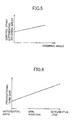
- Fig. 5 is a table showing the relationship between a steering angle and a control start differential rotation speed;
- Fig. 6 is a table showing the relationship between a dial position and a proportional term gain;
- Fig. 7 is a table showing the relationship between a dial position and a third differential limiting torque;
- Fig. 8 is a table showing the relationship between a throttle opening angle and a third differential limiting torque; and
- Fig. 9 is a flowchart showing a differential limiting torque control program of a center differential.
-
- Referring now to Fig. 1, reference numeral 1 denotes an engine mounted on a front part of a vehicle. Driving force of the engine 1 is transmitted to a center differential 3 through an automatic transmission 2 (including a torque converter) and a
transmission output shaft 2a. Further, the driving force of the engine 1 inputs from the center differential 3 to a rear finalreduction gear unit 7 through a rear drive shaft 4, apropeller shaft 5 and a drive pinion 6 and on the other hand the driving force inputs from the center differential 3 to a front final reduction gear unit 11 through atransfer drive gear 8 , a transfer drivengear 9 and a front drive shaft 10. Theautomatic transmission 2 is accommodated integrally with the center differential 3 and the front final reduction gear unit 11 in a casing 12. - The driving force inputted to the rear final
reduction gear unit 7 is transmitted to a rear left wheel 14RL and a rear right wheel 14RR through a rear left drive shaft 13RL and a rear right drive shaft 13RR, respectively. Further, the driving force inputted to the front final reduction gear unit 11 is transmitted to a front left wheel 14FL and a front right wheel 14FR through a front left axle shaft 13FL and a front right axle shaft 13FR, respectively. - The center differential 3 incorporates a first sun gear 15 having a large diameter and mounted on the
transmission output shaft 2a. The first sun gear 15 meshes with afirst pinion 16 having a small diameter, thus constituting a first gear train. - Further, a second sun gear 17 having a small diameter is mounted on the rear drive shaft 4 from which power is transmitted to the rear wheels and meshes with a
second pinion 18 having a large diameter, thus constituting a second gear train. - The
first pinion 16 and thesecond pinion 18 are integrally formed with apinion member 19 which is rotatably supported by a fixed shaft provided in acarrier 20. Further, thecarrier 20 is connected at the front thereof with thetransfer drive gear 8 from which power is transmitted to the front wheels. - Further, the
carrier 20 is rotatably fitted at the front section thereof over theoutput shaft 2a of thetransmission 2 and is rotatably fitted at the rear section thereof over the rear drive shaft 4. Further, the first and second sun gears 15, 17 are accommodated in the central space of thecarrier 20. In Fig. 1, only onepinion member 19 is illustrated, however in an actual construction, a plurality ofpinion members 19 are provided around the sun gears 15, 17. - Thus, the center differential 3 is formed as a compound planetary gear unit having an input member in the
transmission shaft 2a, an output member in the rear drive shaft 4 and the other output member in thecarrier 20. - The center differential 3 of a compound planetary type is provided with a differential function by properly establishing the number of teeth of the first and second sun gears 15, 17 and the first and
second pinions - Further, the center differential 3 is furnished with a desired base torque distribution, for example an unequal torque distribution biased on the rear wheels, by appropriately establishing working pitch circles of the first and second sun gears 15, 17 and the first and
second pinions - Further, the center differential 3 is designed in such a manner that the first and second sun gears 15, 17 and the first and
second pinions respective pinion members 19. Further, a resultant force of separation force and tangential force generated by meshing of the gears exerts on the fixed shaft provided in thecarrier 20, producing another friction torque between therespective pinion members 19 and the respective fixed shafts. Since these friction torques are obtained as a differential limiting torque which is proportional to the input torque, a differential limiting function is given to the center differential 3 itself. - Further, there is provided a center differential clutch (transfer clutch) 21 of the hydraulic multiple disc clutch type for varying the front-to-rear torque distribution between two output members, the
carrier 20 and the rear drive shaft 4, of the center differential 3. When the engagement force of thistransfer clutch 21 is adjusted, the front-to-rear torque distribution ratio can be varied from 50:50 in a fully engaged condition to an inherent front-to-rear torque distribution ratio, for example 35:65, of the center differential 3 in a released condition. - The
transfer clutch 21 is connected with a center differentialclutch drive section 41 constituted by a hydraulic circuit including a plurality of solenoid valves. Hydraulic pressure generated in the center differentialclutch driving section 41 actuates a piston (not shown) to engage or release thetransfer clutch 21. Further, control signals for driving the center differentialclutch drive section 41, that is, input signals to the respective solenoid valves, are outputted from a differentiallimiting control section 40. - The rear final
reduction gear unit 7 comprises adifferential mechanism 22 using bevel gears and a reardifferential clutch 23 using a multiple disc clutch. The reardifferential clutch 23 is provided between adifferential case 25 to which aring gear 24 is fixed and a rear right axle shaft 13RR. Thering gear 24 meshes with the drive pinion 6 to drive thedifferential mechanism 22. - The front final reduction gear unit 11 is constituted by a differential mechanism 26 of bevel gear type and a front disc clutch 27 using multiple discs in the same manner as the rear final
reduction gear unit 7. The front disc clutch 27 is provided between adifferential case 29 to which aring gear 28 is fixed and a front right axle shaft 13FR. Thering gear 28 meshes with a drive pinion of the front drive shaft 10 to drive the differential mechanism 26. - The differential
limiting control section 40 inputs parameters necessary for control from respective sensors and switches. Wheel speeds of the wheels, 14FL, 14FR, 14RL and 14RR are detected by wheel speed sensors 31FL, 31FR, 31RL and 31RR respectively and are inputted to the differentiallimiting control section 40. Further, a steering wheel angle detected by a steeringwheel angle sensor 32 and a throttle opening angle detected by a throttleopening angle sensor 33 are inputted to the differential limitingcontrol section 40, respectively. Further, avariable dial 34 is disposed in an accessible position to a driver to establish a differential limiting torque within a range between a "differential open" position and a "differential lock" position. When the driver adjusts thevariable dial 34 to a desired position, a signal corresponding to that position inputs to the differentiallimiting control section 40. - The differential
limiting control section 40 is constituted by a micro-computer and its interface circuits. As shown in Fig. 2, a vehiclespeed calculating section 40a, a front-rear actual differential rotationspeed calculating section 40b, a front-rear target differential rotationspeed calculating section 40c, a front-rear differential rotation speeddeviation calculating section 40d, a front-rear control start differential rotationspeed establishing section 40e, a front-rear control startcondition judging section 40f, a first front-rear differential limitingtorque calculating section 40g, a second front-rear differential limitingtorque calculating section 40h, a third front-rear differential limitingtorque calculating section 40i and a front-rear differential limitingtorque calculating section 40j. - The vehicle
speed calculating section 40a inputs wheel speeds ωfl, ωfr, ωrl, ωrr of the wheels 14FL, 14FR, 14RL, 14RR from the wheel speed sensors 31FL, 31FR, 31RL, 31RR, respectively. A vehicle speed V is calculated by averaging these wheel speeds and is outputted to the front-rear control start differential rotationspeed calculating section 40e. - The front-rear actual differential rotation
speed calculating section 40b inputs the wheel speeds ωfl, ωfr, ωrl, ωrr of the wheels 14FL, 14FR, 14RL, 14RR from the wheel speed sensors 31FL, 31FR, 31RL, 31RR, respectively and calculates an actual differential rotation speed Δ ω ctr between front and rear drive shafts according to the following formula (1) . The front-rear actual differential rotationspeed calculating section 40b acts as actual differential rotation speed detecting means in the differential limiting control of the center differential. - The actual differential rotation speed Δ ω ctr between front and rear drive shafts calculated in the front-rear actual differential rotation
speed calculating section 40b is outputted to the front-rear differential rotation speeddeviation calculating section 40d and the front-rear control startcondition judging section 40f, respectively. - The front-rear target differential rotation
speed establishing section 40c inputs a signal indicative of a dial position of thevariable dial 34 and establishes a front-rear target differential rotation speed Δ ωctrt by referring to a table showing the relationship between dial position and front-rear target differential rotation speed Δ ωctrt. - Fig. 3 is an example of the table which is obtained from prior experiments and calculations. In the case where a driver prefers a crispy driving and enjoys a good turning ability, the
variable dial 34 is set to a "differential open" position so as to establish the front-rear target differential rotation speed Δω ctrt at a large value. On the other hand, in the case where the driver prefers a steady and safe driving, thevariable dial 34 is set to a "differential lock" position so as to establish the front-rear target differential rotation speed Δ ω ctrt at a small value. The front-rear target differential rotation speed Δ ω ctrt may be corrected by the vehicle speed V in such a manner that as the vehicle speed V becomes large, the front-rear target differential rotation speed Δ ω ctrt becomes smaller. - The front-rear target differential rotation speed Δ ω ctrt established at the front-rear target differential rotation
speed establishing section 40c is outputted to the front-rear differential rotation speeddeviation calculating section 40d. The front-rear target differential rotationspeed establishing section 40c serves as target differential rotation speed establishing means in the differential limiting control of the center differential. - The front-rear differential rotation speed
deviation calculating section 40d calculates a deviation (front-rear differential rotation speed deviation) ε ctr based on the actual differential rotation speed Δ ωctr between the front and rear drive shafts inputted from the front-rear actual differential rotationspeed calculating section 40b and the target differential rotation speed Δ ω ctrt inputted from the front-rear target differential rotationspeed establishing section 40c according to the following formula (2) and is outputted to the first front-rear differential limitingtorque calculating section 40g and the second front-rear differential limitingtorque calculating section 40h, respectively. - The front-rear control start differential rotation
speed establishing section 40e inputs a vehicle speed V from the vehiclespeed calculating section 40a and establishes a front-rear control start differential rotation speed Δ ω ctrs by reference to a table indicating the relationship between front-rear control start differential rotation speed Δ ω ctrs. That relationship is obtained from prior experiments and calculations. - This front-rear control start differential rotation speed Δ ω ctrs is established to a smaller value than the front-rear target differential rotation speed Δ ω ctrt, for example, a lower limit value of the actual differential rotation speed Δ ω ctr between front and rear drive shafts. The front-rear control start differential rotation speed Δ ω ctrs is established by referring to a table as shown in Fig. 4. The table is prepared based on vehicle specifications in consideration of miscellaneous errors encountered in actual traveling.
- Further, according to the embodiment of the present invention, the front-rear control start differential rotation
speed establishing section 40e inputs a signal indicative of a steering wheel angle from the steeringwheel angle sensor 32. The front-rear control start differential rotation speed Δ ω ctrs established in accordance with the vehicle speed V is corrected by the steering angle such that as the steering angle becomes large, the front-rear control start differential rotation speed Δ ωctrs becomes larger as shown in Fig. 5. Thus established front-rear control start differential rotation speed Δ ωctrs is outputted to the front-rear control startcondition judging section 40f. - The front-rear control start
condition judging section 40f inputs the front-rear actual differential rotation speed Δ ω ctr and the front-rear control start differential rotation speed Δ ω ctrs from the front-rear differential rotationspeed calculating section 40b and the front-rear control start differential rotationspeed establishing section 40e, respectively and compares the front-rear actual differential rotation speed Δ ω ct with the front-rear control start differential rotation speed Δ ω ctrs to judge whether or not the start condition of differential control is satisfied. - In the case where the front-rear actual differential rotation speed Δ ωctr is larger than the front-rear control start differential rotation speed Δ ωctrs, the front-rear control start
condition judging section 40f judges that the start condition of differential control has been satisfied and outputs the j udgment to the first front-rear differential limitingtorque calculating section 40g. - The first front-rear differential limiting
torque calculating section 40g inputs a front-rear differential rotation speed deviation ε ctr and the result of the j udgment of the control start from the front-rear differential rotation speeddeviation calculating section 40d and the front-rear control startcondition judging section 40f, respectively and calculates a first front-rear differential limiting torque Tsmcctr according to the following formulas (3) and (4): - In the case of X > 0, the first front-rear differential limiting torque Tsmcctr is let be equal to X and in case of X ≦ 0, the first front-rear differential limiting torque Tsmcctr is let be 0. Further, in case where the control start condition is not satisfied (Δωctr≦ Δωctrs), letting Tsmcctr = 0, ∫ (ε ctr)dt is reset to 0.
- That is, in case where the front-rear actual differential rotation speed Δ ω ctr is smaller than the front-rear control start differential rotation speed Δ ω ctrs, which is a lower limit of the front-rear actual differential rotation speed Δ ω ctr, the first front-rear differential limiting torque Tsmcctr is let be 0 in order to avoid a condition that the
transfer clutch 21 is locked up due to a static friction coefficient. Further, the integration term is prevented from becoming an excessively low value by resetting the integration term ∫ (εctr)dt to 0. If the integration term is too low, when the transfer clutch 21 starts to slip again, the control lag increases and as a result "stick and slip" phenomenon is promoted. Thus calculated first front-rear differential limiting torque Tsmcctr is outputted to the front-rear differential limitingtorque calculating section 40j . - The second front-rear differential limiting
torque calculating section 40h inputs a front-rear differential rotation speed deviation ε ctr and a signal indicative of a dial position from the front-rear differential rotation speeddeviation calculating section 40d and thevariable dial 34, respectively and calculates a second front-rear differential limiting torque Tpcctr according to the following formula (5).variable dial 34. - The table is shown in Fig. 6, in which the proportional term gain kpctr is established to a small value so as to decrease the second front-rear differential limiting torque Tpcctr in the case where the
variable dial 34 is set on a "differential open" side (crispy driving side based on a good turning ability) - On the other hand, in the case where thevariable dial 34 is set on a "differential lock" side (steady and safe driving side), the proportional term gain kpctr is established to a large value so as to increase the second front-rear differential limiting torque Tpcctr. Thus calculated second front-rear differential limiting torque Tpcctr is outputted to the front-rear differential limitingtorque calculating section 40j. - The third front-rear differential limiting
torque calculating section 40i inputs a throttle opening angle and a signal corresponding to a dial position from the throttleopening angle sensor 33 and thevariable dial 34, respectively and establishes a third front-rear differential limiting torque Ti as an initial torque based on these parameters by referring to a table determined by experiments and calculations beforehand. - According to the table, as shown in Fig. 7, when the dial is set on a "differential open" side (crispy driving side), the third front-rear differential limiting torque or the initial torque Ti is established to a small value and when the dial is set on a "differential lock" side (steady and safe driving side), the initial torque Ti is established to a large value. Further, as the throttle opening angle becomes large, the initial torque Ti is established to a larger value according to a table shown in Fig. 8. Thus obtained initial torque Ti is added to the first and second front-rear differential limiting torques as will be described hereinafter. The addition of the initial torque Ti enables to enhance the stability in traveling on a road surface with low friction coefficient. The third front-rear differential limiting torque or initial torque Ti is outputted to the front-rear differential limiting
torque calculating section 40j. - The front-rear differential limiting
torque calculating section 40j inputs the first front-rear differential limiting torque Tsmcctr, the second front-rear differential limiting torque Tpcctr and the initial torque Ti from the first front-rear differential limitingtorque calculating section 40g, the second front-rear differential limitingtorque calculating section 40h and the third front-rear differential limitingtorque calculating section 40i, respectively and calculates a final front-rear differential limiting torque Tlsdctr according to the following formula (6).torque calculating section 40j outputs a signal indicative of hydraulic pressure for producing this final front-rear differential limiting torque Tlsdctr to the center differentialclutch drive section 41. - According to the embodiment, differential limiting torque calculating means are constituted by the front-rear differential rotation speed
deviation calculating section 40d, the first front-rear differential limitingtorque calculating section 40g, the second front-rear differential limitingtorque calculating section 40h , the third front-rear differential limitingtorque calculating section 40i and the front-rear differential limitingtorque calculating section 40j. - Now, a flow of the processes in the differential limiting
control section 40 will be described by reference to a flowchart shown in Fig. 9. - First, at a step (hereinafter abbreviated as "S") 101, wheel speeds ωfl, ωfr, ωrl, ωrr of the respective wheels, 14FL, 14FR, 14RL, 14RR, a steering wheel angle, a throttle opening angle, a dial position indicated by a driver and the like, are read.
- Then, the program goes to S102 where a vehicle speed is calculated in the vehicle
speed calculating section 40a and goes to S103 where a front-rear target differential rotation speed Δ ω ctrt is established in the front-rear target differential rotationspeed establishing section 40c by referring to a map parameterizing dial position and front-rear target differential rotation speed Δ ωctrt. - Next, the program goes to S104 where a front-rear control start differential rotation speed Δ ωctrs is established by referring to a map parameterizing vehicle speed and front-rear control start differential rotation speed Δ ω ctrt after being corrected by the steering wheel angle.
- The program goes to S105 where an actual differential rotation speed Δ ω ctr between front and rear drive shafts is calculated in the front-rear actual differential rotation
speed calculating section 40b according to the formula (1). - After that, the program goes to S106 where the front-rear actual differential rotation speed Δ ωctr is compared with the front-rear control start differential rotation speed Δ ωctrs in the front-rear control start
condition judging section 40f and when it is judged that the control start condition is satisfied, goes to S107. - At S107, a front-rear differential rotation speed deviation ε ctr is calculated in the front-rear differential rotation speed
deviation calculating section 40d according to the formula (2) and the program goes to S108. - At S108, the front-rear differential rotation speed deviation ε ctr is integrated from 0 to t in the first front-rear differential limiting
torque calculating section 40g and the program goes to S109 where a first front-rear differential limiting torque Tsmcctr is calculated in the same differential limitingtorque calculating section 40g. The first front-rear differential limiting torque Tsmcctr depends upon X calculated in the formula (4). In the case of X > 0, the first front-rear differential limiting torque Tsmcctr is let be equal to X and in the case of X ≤ 0, the first front-rear differential limiting torque Tsmcctr is let be 0. Then the program goes to S110. - On the other hand, in the case where at S106 the front-rear differential rotation speed Δωctr is smaller than the front-rear control start differential rotation speed Δ ω cts , it is judged that the control start condition is not satisfied and the program goes to S115. At S115, the front-rear differential limiting torque Tsmcctr is established to 0, Then the program goes to S116 where the integral of the εctr is reset to 0 and goes to S110.
- When the program goes from S109 or S116 to S110, a proportional term gain kpctr is established by reference to the table of the proportional term gain in the second front-rear differential limiting
torque calculating section 40h and the program goes to S111 where a second front-rear differential limiting torque Tpcctr, namely, a proportional term is calculated according to the formula (5). - Next, the program goes to S112 where a third front-rear differential limiting torque, namely, an initial torque Ti is calculated based on the throttle opening angle and the dial position in the front-rear differential limiting
torque calculating section 40i. - Then, the program goes to S113 where a final front-rear differential limiting torque Tlsdctr is calculated by summing up the first front-rear differential limiting torque Tsmcctr, the second front-rear differential limiting torque Tpcctr and the initial torque Ti according to the formula (6) in the front-rear differential limiting
torque calculating section 40j and then goes to S114 where a signal indicative of hydraulic pressure for producing this final front-rear differential limiting torque TIsdctr is outputted to the center differentialclutch drive section 41, leaving the routine. - Thus, according to the embodiment, since a differential limiting torque inputted by manual operation is corrected by traveling conditions and road surface conditions, an optimum maneuverability reflecting a driver's intention can be obtained.
- In this embodiment, the power distribution control between front and rear wheels, that is, the control of the transfer clutch 21 provided between front and rear drive shafts is described, however the principle of the present invention can be applied to the control of the rear differential clutch 23 or the front differential clutch 27.
- The entire contents of Japanese Patent Application No. Tokugan 2002-228997 filed August 6, 2002, is incorporated herein by reference.
- While the present invention has been disclosed in terms of the preferred embodiment in order to facilitate better understanding of the invention, it should be appreciated that the invention can be embodied in various ways without departing from the scope of the invention. Therefore, the invention should be understood to include all possible embodiments which can be embodied without departing from the scope of the invention.
Claims (8)
- A power distribution control apparatus of a vehicle for distributing an input torque transmitted through an input shaft into a first output torque and a second output torque through a first output shaft and a second output shaft, respectively by means of a differential mechanism and for controlling a distribution ratio of said first output torque to said second output torque by controlling an engagement force of a clutch mechanism provided between said first output shaft and said second output shaft, comprising:target differential rotation speed establishing means for selectively establishing a target differential rotation speed between said first and second output shafts;actual differential rotation speed detecting means for detecting an actual differential rotation speed between said first and second output shafts; anddifferential limiting torque establishing means for selectively establishing a differential limiting torque of said clutch at least based on said target differential rotation speed, said actual differential rotation speed and a deviation between said target differential rotation speed and said actual differential rotation speed.
- The power distribution control apparatus according to claim 1, wherein said differential limiting torque establishing means include first differential limiting torque calculating means for calculating a first differential limiting torque at least based on a time-versus integration of said deviation, second differential limiting torque calculating means for calculating a second differential limiting torque based on said deviation and a proportional term gain selectively established, and a third differential limiting torque establishing means for selectively establishing an initial torque at least based on a throttle opening angle and finally establish said differential limiting torque by summing up said first differential limiting torque, said second differential limiting torque and said initial torque.
- The power distribution control apparatus according to claim 1 or claim 2, wherein said clutch mechanism is provided between said first output shaft connected with front wheels and said second output shaft connected with rear wheels.
- The power distribution control apparatus according to any of claims 1 to 3, wherein said target differential rotation speed is established by a variable dial.
- The power distribution control apparatus according to any of claims 1 to 4, wherein said proportional term gain is established by a variable dial.
- The power distribution control apparatus according to any of claims 1 to 5, wherein said clutch mechanism is provided between said first output shaft connected with a left wheel and said second output shaft connected with a right wheel.
- A vehicular power distribution control method of distributing an input torque transmitted through an input shaft into a first output torque and a second output torque through a first output shaft and a second output shaft, respectively by means of a differential mechanism and controlling a distribution ratio of said first output torque to said second output torque by controlling an engagement force of a clutch mechanism provided between said first output shaft and said second output shaft, comprising the steps of:selectively establishing a target differential rotation speed between said first and second output shafts;detecting an actual differential rotation speed between said first and second output shafts; andselectively establishing a differential limiting torque of said clutch mechanism at least based on said target differential rotation speed, said actual differential rotation speed and a deviation between said target differential rotation speed and said actual differential rotation speed.
- A vehicle comprising a power distribution control apparatus as claimed in any of claims 1 to 6 or operating in accordance with a method as claimed in claim 7.
Applications Claiming Priority (2)
| Application Number | Priority Date | Filing Date | Title |
|---|---|---|---|
| JP2002228997A JP4265891B2 (en) | 2002-08-06 | 2002-08-06 | Vehicle driving force transmission control device |
| JP2002228997 | 2002-08-06 |
Publications (3)
| Publication Number | Publication Date |
|---|---|
| EP1388454A2 true EP1388454A2 (en) | 2004-02-11 |
| EP1388454A3 EP1388454A3 (en) | 2006-06-07 |
| EP1388454B1 EP1388454B1 (en) | 2012-06-20 |
Family
ID=30437741
Family Applications (1)
| Application Number | Title | Priority Date | Filing Date |
|---|---|---|---|
| EP03254881A Expired - Fee Related EP1388454B1 (en) | 2002-08-06 | 2003-08-06 | Power distribution control apparatus and control method |
Country Status (3)
| Country | Link |
|---|---|
| US (1) | US6878085B2 (en) |
| EP (1) | EP1388454B1 (en) |
| JP (1) | JP4265891B2 (en) |
Cited By (2)
| Publication number | Priority date | Publication date | Assignee | Title |
|---|---|---|---|---|
| EP2137422A4 (en) * | 2007-03-19 | 2016-03-09 | Eaton Corp | Idle-able power transfer unit |
| CN108137037A (en) * | 2015-10-19 | 2018-06-08 | 罗伯特·博世有限公司 | Control device, power train and method |
Families Citing this family (14)
| Publication number | Priority date | Publication date | Assignee | Title |
|---|---|---|---|---|
| JP4263441B2 (en) | 2002-08-07 | 2009-05-13 | 富士重工業株式会社 | Control device for four-wheel drive vehicle |
| AT7553U1 (en) * | 2004-02-23 | 2005-05-25 | Magna Drivetrain Ag & Co Kg | DRIVE TRAIN OF A ALL-ROAD GEARED VEHICLE |
| JP4781695B2 (en) * | 2005-03-09 | 2011-09-28 | 富士重工業株式会社 | Control device for four-wheel drive vehicle |
| US7448977B2 (en) * | 2005-10-21 | 2008-11-11 | Ford Global Technologies, Llc | Motor vehicle transaxle having a differential mechanism controlled by an on-demand clutch |
| US7309301B2 (en) * | 2005-10-21 | 2007-12-18 | Ford Global Technologies, Llc | Transaxle having a differential mechanism and on-demand transfer clutch |
| US7873457B2 (en) * | 2006-04-26 | 2011-01-18 | Magna Steyr Fahrzeugtechnik Ag & Co Kg | Clutch control system for power transfer unit in four-wheel drive vehicle |
| DE102008015604A1 (en) * | 2008-03-26 | 2009-10-01 | Audi Ag | Method for monitoring operating states of motor vehicles |
| US8771140B2 (en) | 2008-12-22 | 2014-07-08 | Caterpillar Inc. | Machine control system utilizing inertial yaw sensor |
| US9086104B2 (en) | 2008-12-22 | 2015-07-21 | Caterpillar Inc. | System and method for controlling wheel spin and wheel slip on a machine having differentially driven wheels |
| US9296295B2 (en) | 2008-12-22 | 2016-03-29 | Caterpillar Inc. | Machine control system utilizing inertial yaw sensor |
| US9126480B2 (en) | 2008-12-22 | 2015-09-08 | Caterpillar Inc. | Machine control system utilizing inertial yaw sensor |
| US20110269595A1 (en) | 2010-04-30 | 2011-11-03 | American Axle & Manufacturing Inc. | Control strategy for operating a locking differential |
| JP5720165B2 (en) * | 2010-10-05 | 2015-05-20 | 株式会社ジェイテクト | Four-wheel drive vehicle |
| US8875833B2 (en) * | 2012-12-31 | 2014-11-04 | Kawasaki Jukogyo Kabushiki Kaisha | Utility vehicle |
Citations (8)
| Publication number | Priority date | Publication date | Assignee | Title |
|---|---|---|---|---|
| US792174A (en) | 1904-05-16 | 1905-06-13 | Charles W Squires | Electric railway-switch-operating device. |
| US5314490A (en) | 1992-04-03 | 1994-05-24 | Sulzer Medizinaltechnik Ag | Outer cup for an artificial hipjoint socket |
| US5326367A (en) | 1991-09-10 | 1994-07-05 | Howmedica Gmbh | Endoprosthesis for a cancer damaged pelvis |
| US5326368A (en) | 1992-09-22 | 1994-07-05 | Howmedica, Inc. | Modular acetabular cup |
| US5702477A (en) | 1996-05-09 | 1997-12-30 | Osteonics Corp. | Acetabular shell with supplemental support and method |
| US5871548A (en) | 1996-12-07 | 1999-02-16 | Johnson & Johnson Professional, Inc. | Modular acetabular reinforcement system |
| US5931870A (en) | 1996-10-09 | 1999-08-03 | Smith & Nephew, Inc. | Acetabular ring prosthesis with reinforcement buttress |
| US6162257A (en) | 1997-10-31 | 2000-12-19 | Gustilo; Ramon B. | Acetabular cup prosthesis with extension for deficient acetabulum |
Family Cites Families (18)
| Publication number | Priority date | Publication date | Assignee | Title |
|---|---|---|---|---|
| US55416A (en) * | 1866-06-05 | Improved mail-bag | ||
| DE3643831A1 (en) * | 1986-12-20 | 1988-07-07 | Deere & Co | DRIVE SYSTEM FOR THE WHEELS OF TWO WHEEL COUPLES |
| JPS644530A (en) * | 1987-06-26 | 1989-01-09 | Toyota Motor Corp | Control device in differential operation limiting device in four-wheel-drive vehicle |
| JP2615085B2 (en) * | 1987-10-27 | 1997-05-28 | 富士重工業株式会社 | Traction control device for four-wheel drive vehicle |
| JP2706259B2 (en) * | 1988-04-28 | 1998-01-28 | 日産自動車株式会社 | Differential limit torque control device |
| US5052988A (en) * | 1990-11-16 | 1991-10-01 | Aisin Aw Co., Ltd. | Differential control system |
| US5332059A (en) * | 1991-04-26 | 1994-07-26 | Fuji Jukogyo Kabushiki Kaisha | Control system for a differential of a motor vehicle |
| JP3009942B2 (en) * | 1991-06-27 | 2000-02-14 | マツダ株式会社 | Vehicle control device |
| JPH054530A (en) * | 1991-06-27 | 1993-01-14 | Mazda Motor Corp | Differential limit device for vehicle |
| DE4202026A1 (en) * | 1992-01-25 | 1993-07-29 | Deere & Co | DRIVE ARRANGEMENT FOR CONTROLLING AND DISTRIBUTING THE DRIVE FOR A VEHICLE |
| JP3157244B2 (en) * | 1992-02-06 | 2001-04-16 | マツダ株式会社 | Vehicle differential limiter |
| JP3301183B2 (en) * | 1993-11-24 | 2002-07-15 | 日産自動車株式会社 | Driving force distribution control device between front and rear wheels of vehicle |
| JP3268124B2 (en) * | 1994-06-27 | 2002-03-25 | 富士重工業株式会社 | Vehicle torque distribution control device |
| JPH08132914A (en) | 1994-11-11 | 1996-05-28 | Fuji Heavy Ind Ltd | Burning preventing device for longitudinal torque distribution control device in vehicle provided with manual transmission |
| JP2001071776A (en) | 1999-09-03 | 2001-03-21 | Tochigi Fuji Ind Co Ltd | Differential limitation control method and control system |
| WO2001026925A1 (en) * | 1999-10-12 | 2001-04-19 | Robert Bosch Gmbh | Method and device for exercising a differential blocking function for a vehicle |
| JP4456748B2 (en) * | 2000-10-27 | 2010-04-28 | 富士重工業株式会社 | Power distribution control device for four-wheel drive vehicles |
| JP4309089B2 (en) * | 2002-02-14 | 2009-08-05 | 富士重工業株式会社 | Vehicle driving force transmission control device |
-
2002
- 2002-08-06 JP JP2002228997A patent/JP4265891B2/en not_active Expired - Fee Related
-
2003
- 2003-08-06 EP EP03254881A patent/EP1388454B1/en not_active Expired - Fee Related
- 2003-08-06 US US10/634,802 patent/US6878085B2/en not_active Expired - Fee Related
Patent Citations (8)
| Publication number | Priority date | Publication date | Assignee | Title |
|---|---|---|---|---|
| US792174A (en) | 1904-05-16 | 1905-06-13 | Charles W Squires | Electric railway-switch-operating device. |
| US5326367A (en) | 1991-09-10 | 1994-07-05 | Howmedica Gmbh | Endoprosthesis for a cancer damaged pelvis |
| US5314490A (en) | 1992-04-03 | 1994-05-24 | Sulzer Medizinaltechnik Ag | Outer cup for an artificial hipjoint socket |
| US5326368A (en) | 1992-09-22 | 1994-07-05 | Howmedica, Inc. | Modular acetabular cup |
| US5702477A (en) | 1996-05-09 | 1997-12-30 | Osteonics Corp. | Acetabular shell with supplemental support and method |
| US5931870A (en) | 1996-10-09 | 1999-08-03 | Smith & Nephew, Inc. | Acetabular ring prosthesis with reinforcement buttress |
| US5871548A (en) | 1996-12-07 | 1999-02-16 | Johnson & Johnson Professional, Inc. | Modular acetabular reinforcement system |
| US6162257A (en) | 1997-10-31 | 2000-12-19 | Gustilo; Ramon B. | Acetabular cup prosthesis with extension for deficient acetabulum |
Cited By (3)
| Publication number | Priority date | Publication date | Assignee | Title |
|---|---|---|---|---|
| EP2137422A4 (en) * | 2007-03-19 | 2016-03-09 | Eaton Corp | Idle-able power transfer unit |
| CN108137037A (en) * | 2015-10-19 | 2018-06-08 | 罗伯特·博世有限公司 | Control device, power train and method |
| US10864902B2 (en) | 2015-10-19 | 2020-12-15 | Robert Bosch Gmbh | Control device, drive train and method |
Also Published As
| Publication number | Publication date |
|---|---|
| EP1388454A3 (en) | 2006-06-07 |
| US20040026154A1 (en) | 2004-02-12 |
| JP2004066961A (en) | 2004-03-04 |
| US6878085B2 (en) | 2005-04-12 |
| EP1388454B1 (en) | 2012-06-20 |
| JP4265891B2 (en) | 2009-05-20 |
Similar Documents
| Publication | Publication Date | Title |
|---|---|---|
| EP1388454B1 (en) | Power distribution control apparatus and control method | |
| EP1686031B1 (en) | Control device for a four-wheel drive vehicle | |
| EP1403124B1 (en) | Differential limiting control apparatus for a vehicle and the method thereof | |
| EP0314453B1 (en) | Traction control system for a four-wheel drive motor vehicle | |
| EP1388453B1 (en) | Control apparatus and method for four wheel drive vehicle | |
| EP0963892A2 (en) | Torque distribution control apparatus for 4 wheel driven vehicle | |
| US7386383B2 (en) | Differential limiting control apparatus for a vehicle and the method thereof | |
| EP1342608B1 (en) | Driving force transmission control system for automative vehicle and the method thereof | |
| JPH02290730A (en) | Torque distribution control device of four-wheel drive vehicle | |
| EP1674320A1 (en) | Power transfer device for a four-wheel drive vehicle | |
| EP0421594A1 (en) | Torque distribution control system for a four wheel drive motor vehicle | |
| US6932180B2 (en) | Differential limiting control apparatus for vehicle | |
| EP1731349B1 (en) | Front and rear drive power distribution control device for vehicle | |
| JP2970913B2 (en) | Torque distribution control device for four-wheel drive vehicle | |
| JP5039000B2 (en) | Driving force control device | |
| JP2662958B2 (en) | Slip detector for four-wheel drive vehicles | |
| JP3326081B2 (en) | Engine idle detection method and driving force distribution device using the same | |
| JP2001097065A (en) | Vehicular power distribution control device | |
| JP6421210B2 (en) | Torque distribution control device for four-wheel drive vehicle | |
| JP3352728B2 (en) | Control method of rear wheel differential limiting device | |
| JP2001071776A (en) | Differential limitation control method and control system | |
| JP2662959B2 (en) | Slip detector for four-wheel drive vehicles | |
| JPH05338459A (en) | Torque distribution controller for four-wheel drive vehicle | |
| JPH06171386A (en) | Center differential type four-wheel drive vehicle with differential limiting mechanism | |
| JPH04169328A (en) | Unequal torque distributional controller of four-wheel driving car |
Legal Events
| Date | Code | Title | Description |
|---|---|---|---|
| PUAI | Public reference made under article 153(3) epc to a published international application that has entered the european phase |
Free format text: ORIGINAL CODE: 0009012 |
|
| AK | Designated contracting states |
Kind code of ref document: A2 Designated state(s): AT BE BG CH CY CZ DE DK EE ES FI FR GB GR HU IE IT LI LU MC NL PT RO SE SI SK TR |
|
| AX | Request for extension of the european patent |
Extension state: AL LT LV MK |
|
| PUAL | Search report despatched |
Free format text: ORIGINAL CODE: 0009013 |
|
| AK | Designated contracting states |
Kind code of ref document: A3 Designated state(s): AT BE BG CH CY CZ DE DK EE ES FI FR GB GR HU IE IT LI LU MC NL PT RO SE SI SK TR |
|
| AX | Request for extension of the european patent |
Extension state: AL LT LV MK |
|
| AKX | Designation fees paid | ||
| 17P | Request for examination filed |
Effective date: 20061114 |
|
| RBV | Designated contracting states (corrected) |
Designated state(s): DE |
|
| REG | Reference to a national code |
Ref country code: DE Ref legal event code: 8566 |
|
| 17Q | First examination report despatched |
Effective date: 20100104 |
|
| GRAP | Despatch of communication of intention to grant a patent |
Free format text: ORIGINAL CODE: EPIDOSNIGR1 |
|
| GRAS | Grant fee paid |
Free format text: ORIGINAL CODE: EPIDOSNIGR3 |
|
| GRAA | (expected) grant |
Free format text: ORIGINAL CODE: 0009210 |
|
| AK | Designated contracting states |
Kind code of ref document: B1 Designated state(s): DE |
|
| REG | Reference to a national code |
Ref country code: DE Ref legal event code: R081 Ref document number: 60341330 Country of ref document: DE Owner name: SUBARU CORPORATION, JP Free format text: FORMER OWNER: FUJI JUKOGYO K.K., TOKIO/TOKYO, JP |
|
| REG | Reference to a national code |
Ref country code: DE Ref legal event code: R096 Ref document number: 60341330 Country of ref document: DE Effective date: 20120816 |
|
| PLBE | No opposition filed within time limit |
Free format text: ORIGINAL CODE: 0009261 |
|
| STAA | Information on the status of an ep patent application or granted ep patent |
Free format text: STATUS: NO OPPOSITION FILED WITHIN TIME LIMIT |
|
| 26N | No opposition filed |
Effective date: 20130321 |
|
| REG | Reference to a national code |
Ref country code: DE Ref legal event code: R097 Ref document number: 60341330 Country of ref document: DE Effective date: 20130321 |
|
| PGFP | Annual fee paid to national office [announced via postgrant information from national office to epo] |
Ref country code: DE Payment date: 20150729 Year of fee payment: 13 |
|
| REG | Reference to a national code |
Ref country code: DE Ref legal event code: R119 Ref document number: 60341330 Country of ref document: DE |
|
| REG | Reference to a national code |
Ref country code: DE Ref legal event code: R082 Ref document number: 60341330 Country of ref document: DE Representative=s name: VOSSIUS & PARTNER PATENTANWAELTE RECHTSANWAELT, DE Ref country code: DE Ref legal event code: R081 Ref document number: 60341330 Country of ref document: DE Owner name: SUBARU CORPORATION, JP Free format text: FORMER OWNER: FUJI JUKOGYO KABUSHIKI KAISHA, TOKYO, JP |
|
| PG25 | Lapsed in a contracting state [announced via postgrant information from national office to epo] |
Ref country code: DE Free format text: LAPSE BECAUSE OF NON-PAYMENT OF DUE FEES Effective date: 20170301 |