EP1387789B1 - Improved structural reinforcement - Google Patents
Improved structural reinforcement Download PDFInfo
- Publication number
- EP1387789B1 EP1387789B1 EP02750918A EP02750918A EP1387789B1 EP 1387789 B1 EP1387789 B1 EP 1387789B1 EP 02750918 A EP02750918 A EP 02750918A EP 02750918 A EP02750918 A EP 02750918A EP 1387789 B1 EP1387789 B1 EP 1387789B1
- Authority
- EP
- European Patent Office
- Prior art keywords
- reinforcing member
- structural
- adhesive material
- expandable adhesive
- hollow
- Prior art date
- Legal status (The legal status is an assumption and is not a legal conclusion. Google has not performed a legal analysis and makes no representation as to the accuracy of the status listed.)
- Expired - Lifetime
Links
- 230000002787 reinforcement Effects 0.000 title claims abstract description 34
- 230000003014 reinforcing effect Effects 0.000 claims abstract description 118
- 239000000463 material Substances 0.000 claims abstract description 82
- 230000001070 adhesive effect Effects 0.000 claims abstract description 75
- 239000000853 adhesive Substances 0.000 claims abstract description 74
- 238000000034 method Methods 0.000 claims description 30
- 230000008569 process Effects 0.000 claims description 22
- 230000004913 activation Effects 0.000 claims description 9
- 239000006260 foam Substances 0.000 claims description 9
- 238000010438 heat treatment Methods 0.000 claims description 6
- 239000004952 Polyamide Substances 0.000 claims description 3
- 229920002647 polyamide Polymers 0.000 claims description 3
- 229920005989 resin Polymers 0.000 claims description 3
- 239000011347 resin Substances 0.000 claims description 3
- 229920001187 thermosetting polymer Polymers 0.000 claims description 3
- OKTJSMMVPCPJKN-UHFFFAOYSA-N Carbon Chemical group [C] OKTJSMMVPCPJKN-UHFFFAOYSA-N 0.000 claims description 2
- 229910052799 carbon Inorganic materials 0.000 claims description 2
- 230000001413 cellular effect Effects 0.000 claims description 2
- 238000004070 electrodeposition Methods 0.000 claims description 2
- 239000000835 fiber Substances 0.000 claims description 2
- 230000006698 induction Effects 0.000 claims description 2
- 239000000945 filler Substances 0.000 claims 2
- 239000003365 glass fiber Substances 0.000 claims 1
- 239000011248 coating agent Substances 0.000 description 12
- 238000000576 coating method Methods 0.000 description 12
- 229910052751 metal Inorganic materials 0.000 description 10
- 239000002184 metal Substances 0.000 description 10
- 238000000465 moulding Methods 0.000 description 10
- 238000001746 injection moulding Methods 0.000 description 8
- 238000004519 manufacturing process Methods 0.000 description 8
- 238000005260 corrosion Methods 0.000 description 6
- 239000012530 fluid Substances 0.000 description 6
- 230000007797 corrosion Effects 0.000 description 4
- 230000009467 reduction Effects 0.000 description 4
- 239000012779 reinforcing material Substances 0.000 description 4
- 229920001169 thermoplastic Polymers 0.000 description 4
- 239000004416 thermosoftening plastic Substances 0.000 description 4
- 238000005868 electrolysis reaction Methods 0.000 description 3
- 239000011521 glass Substances 0.000 description 3
- 239000004033 plastic Substances 0.000 description 3
- 239000004616 structural foam Substances 0.000 description 3
- 239000004677 Nylon Substances 0.000 description 2
- 229910052782 aluminium Inorganic materials 0.000 description 2
- XAGFODPZIPBFFR-UHFFFAOYSA-N aluminium Chemical compound [Al] XAGFODPZIPBFFR-UHFFFAOYSA-N 0.000 description 2
- 230000006835 compression Effects 0.000 description 2
- 238000007906 compression Methods 0.000 description 2
- 238000010276 construction Methods 0.000 description 2
- 238000001125 extrusion Methods 0.000 description 2
- 229920001778 nylon Polymers 0.000 description 2
- UWCBNAVPISMFJZ-GFCCVEGCSA-N 2-[2-[(2r)-3-(tert-butylamino)-2-hydroxypropoxy]phenoxy]-n-methylacetamide Chemical compound CNC(=O)COC1=CC=CC=C1OC[C@H](O)CNC(C)(C)C UWCBNAVPISMFJZ-GFCCVEGCSA-N 0.000 description 1
- 238000010521 absorption reaction Methods 0.000 description 1
- 230000015572 biosynthetic process Effects 0.000 description 1
- 230000000903 blocking effect Effects 0.000 description 1
- 230000008859 change Effects 0.000 description 1
- 238000000748 compression moulding Methods 0.000 description 1
- 238000011109 contamination Methods 0.000 description 1
- 238000005336 cracking Methods 0.000 description 1
- 238000004512 die casting Methods 0.000 description 1
- 238000001035 drying Methods 0.000 description 1
- 230000009977 dual effect Effects 0.000 description 1
- 230000000694 effects Effects 0.000 description 1
- 238000007765 extrusion coating Methods 0.000 description 1
- 239000000446 fuel Substances 0.000 description 1
- 238000009863 impact test Methods 0.000 description 1
- 239000007788 liquid Substances 0.000 description 1
- 229910001092 metal group alloy Inorganic materials 0.000 description 1
- 239000002991 molded plastic Substances 0.000 description 1
- 238000010137 moulding (plastic) Methods 0.000 description 1
- 239000003973 paint Substances 0.000 description 1
- 230000002265 prevention Effects 0.000 description 1
- 238000001179 sorption measurement Methods 0.000 description 1
- XLYOFNOQVPJJNP-UHFFFAOYSA-N water Substances O XLYOFNOQVPJJNP-UHFFFAOYSA-N 0.000 description 1
Images


Classifications
-
- B—PERFORMING OPERATIONS; TRANSPORTING
- B62—LAND VEHICLES FOR TRAVELLING OTHERWISE THAN ON RAILS
- B62D—MOTOR VEHICLES; TRAILERS
- B62D29/00—Superstructures, understructures, or sub-units thereof, characterised by the material thereof
- B62D29/001—Superstructures, understructures, or sub-units thereof, characterised by the material thereof characterised by combining metal and synthetic material
- B62D29/002—Superstructures, understructures, or sub-units thereof, characterised by the material thereof characterised by combining metal and synthetic material a foamable synthetic material or metal being added in situ
-
- B—PERFORMING OPERATIONS; TRANSPORTING
- B62—LAND VEHICLES FOR TRAVELLING OTHERWISE THAN ON RAILS
- B62D—MOTOR VEHICLES; TRAILERS
- B62D25/00—Superstructure or monocoque structure sub-units; Parts or details thereof not otherwise provided for
-
- Y—GENERAL TAGGING OF NEW TECHNOLOGICAL DEVELOPMENTS; GENERAL TAGGING OF CROSS-SECTIONAL TECHNOLOGIES SPANNING OVER SEVERAL SECTIONS OF THE IPC; TECHNICAL SUBJECTS COVERED BY FORMER USPC CROSS-REFERENCE ART COLLECTIONS [XRACs] AND DIGESTS
- Y10—TECHNICAL SUBJECTS COVERED BY FORMER USPC
- Y10T—TECHNICAL SUBJECTS COVERED BY FORMER US CLASSIFICATION
- Y10T428/00—Stock material or miscellaneous articles
- Y10T428/13—Hollow or container type article [e.g., tube, vase, etc.]
- Y10T428/1352—Polymer or resin containing [i.e., natural or synthetic]
- Y10T428/1376—Foam or porous material containing
-
- Y—GENERAL TAGGING OF NEW TECHNOLOGICAL DEVELOPMENTS; GENERAL TAGGING OF CROSS-SECTIONAL TECHNOLOGIES SPANNING OVER SEVERAL SECTIONS OF THE IPC; TECHNICAL SUBJECTS COVERED BY FORMER USPC CROSS-REFERENCE ART COLLECTIONS [XRACs] AND DIGESTS
- Y10—TECHNICAL SUBJECTS COVERED BY FORMER USPC
- Y10T—TECHNICAL SUBJECTS COVERED BY FORMER US CLASSIFICATION
- Y10T428/00—Stock material or miscellaneous articles
- Y10T428/24—Structurally defined web or sheet [e.g., overall dimension, etc.]
- Y10T428/24628—Nonplanar uniform thickness material
-
- Y—GENERAL TAGGING OF NEW TECHNOLOGICAL DEVELOPMENTS; GENERAL TAGGING OF CROSS-SECTIONAL TECHNOLOGIES SPANNING OVER SEVERAL SECTIONS OF THE IPC; TECHNICAL SUBJECTS COVERED BY FORMER USPC CROSS-REFERENCE ART COLLECTIONS [XRACs] AND DIGESTS
- Y10—TECHNICAL SUBJECTS COVERED BY FORMER USPC
- Y10T—TECHNICAL SUBJECTS COVERED BY FORMER US CLASSIFICATION
- Y10T428/00—Stock material or miscellaneous articles
- Y10T428/249921—Web or sheet containing structurally defined element or component
- Y10T428/249953—Composite having voids in a component [e.g., porous, cellular, etc.]
- Y10T428/249981—Plural void-containing components
-
- Y—GENERAL TAGGING OF NEW TECHNOLOGICAL DEVELOPMENTS; GENERAL TAGGING OF CROSS-SECTIONAL TECHNOLOGIES SPANNING OVER SEVERAL SECTIONS OF THE IPC; TECHNICAL SUBJECTS COVERED BY FORMER USPC CROSS-REFERENCE ART COLLECTIONS [XRACs] AND DIGESTS
- Y10—TECHNICAL SUBJECTS COVERED BY FORMER USPC
- Y10T—TECHNICAL SUBJECTS COVERED BY FORMER US CLASSIFICATION
- Y10T428/00—Stock material or miscellaneous articles
- Y10T428/249921—Web or sheet containing structurally defined element or component
- Y10T428/249953—Composite having voids in a component [e.g., porous, cellular, etc.]
- Y10T428/249987—With nonvoid component of specified composition
- Y10T428/249991—Synthetic resin or natural rubbers
-
- Y—GENERAL TAGGING OF NEW TECHNOLOGICAL DEVELOPMENTS; GENERAL TAGGING OF CROSS-SECTIONAL TECHNOLOGIES SPANNING OVER SEVERAL SECTIONS OF THE IPC; TECHNICAL SUBJECTS COVERED BY FORMER USPC CROSS-REFERENCE ART COLLECTIONS [XRACs] AND DIGESTS
- Y10—TECHNICAL SUBJECTS COVERED BY FORMER USPC
- Y10T—TECHNICAL SUBJECTS COVERED BY FORMER US CLASSIFICATION
- Y10T428/00—Stock material or miscellaneous articles
- Y10T428/28—Web or sheet containing structurally defined element or component and having an adhesive outermost layer
- Y10T428/2852—Adhesive compositions
- Y10T428/287—Adhesive compositions including epoxy group or epoxy polymer
Definitions
- the present invention relates to reinforcing materials and in particular to reinforcing materials that can be provided in hollow cross-sectional members particularly to provide reinforcement to improve the structural integrity of vehicles.
- the invention further provides a system whereby reinforcement can be provided whilst ensuring effective provision of an anti-corrosion coating on the inner surface of the hollow cross-sectional member by the electrocoat process.
- the electrocoat process used in vehicle manufacture is a process in which the vehicle structure is passed through a bath of anticorrosion fluid and the vehicle structure is used as an electrode whereby an anticorrosion coating is deposited from the fluid onto the vehicle structure by electrolysis. The coating is then baked by heating.
- the trends in motor vehicle design are towards lighter vehicles to improve fuel consumption.
- the safety standards and requirements are becoming more rigorous as indicated by the European Union requirements and the Euro-NCAP impact testing.
- the use of lighter materials such as aluminum to produce the hollow cross-sectional members that are used as vehicle sub frames has lead to the need for additional reinforcement.
- the form of reinforcement required can vary from one location in the vehicle to another and from vehicle to vehicle.
- the present invention therefore improves the strength of vehicles structures made from existing materials and enables vehicle structures based on lighter materials to contribute to safety requirements.
- Crash protection where the prevention of vehicle body deformation is important to provide protection for the occupants.
- Energy absorption to enhance performance after yield.
- the reduction of mechanical constraints such as compression, shear torsion and flexing, or body movement in the vehicle structure particularly to improve durability and reduce stress cracking and the point mobility problems requiring the reduction of resonance by the provision of stiffening.
- the need for reinforcement is present irrespective of the materials that are used to produce the vehicle structure and the need varies from material to material and according to the nature of the reinforcement that is being provided.
- the reinforcing parts can also reduce the noise created by the motion of a vehicle by providing a sound deadening effect as a result of blocking air paths in cavities.
- a vehicle structure In the electrocoat process a vehicle structure is immersed in a bath of coating fluid from which an anticorrosion coating is deposited on the metal by electrolysis. The vehicle metal structure is subsequently heated to bake the coating on the metal.
- the electrocoat process is typically applied to complete vehicle structures in which hollow sections have been capped. Accordingly reinforcing structures are preferably provided within hollow sections prior to the electrocoat. It is therefore important that the reinforcing structure have minimal impact on the operation and efficiency of the electrocoat process.
- reinforcing materials have either been stuck to the metal structure prior to subjecting the vehicle structure to the electrocoat process or have been provided after the electrocoat process.
- the former technique has the problem that it is not possible to perform the electrocoat over the entire surface, which can lead to local areas of corrosion.
- the latter technique is cumbersome and requires the provision of fastening means after electrocoating, which can damage the electrocoat and again lead to local areas of corrosion.
- the metallic or moulded member is coated with an expandable adhesive material.
- the expandable adhesive material being such that it will expand at temperatures to which the automobile is exposed during manufacture such as in the curing stage of the electrocoat process or in the paint oven.
- the reinforcing member is therefore placed within the cavity of the vehicle with the coating of the expandable adhesive material being in an unfoamed state.
- the expandable adhesive material will be brought to its expansion temperature and will expand to fill the gap between the inner surface of the vehicle structural member and the reinforcing member to bond the reinforcing member to the inner surface of the vehicle structural member. In this way a light and strong structural reinforcement is provided.
- the present invention is aimed at providing such improved structural reinforcement systems.
- the present invention therefore provides a structural reinforcing member for reinforcing a hollow structural member according claim 1.
- the provision of the extensions on the mouldings according to the present invention can serve a dual function. Some or all of the extensions can provide local areas of the reinforcing member which when in place are closer to the inner surface of the hollow structural member than the remaining bulk of the reinforcing member. In this way the extensions may be located and designed to reduce deformation of the hollow structural member on impact. At least one, preferably at least two, of the pairs of extensions also direct the expansion of the expandable adhesive material to ensure that there is adhesion between the reinforcing member and the internal surface of the structural member where adhesion is required. This in turn enables selective use of the expandable adhesive material and can obviate the need to coat the entire surfaces of the reinforcing member that face the internal surfaces of the hollow structural member with the expandable adhesive material.
- the dimensions of the rigid reinforcing member and the thickness and nature of the expandable adhesive material are important to the achievement of the desired structural reinforcement.
- the exterior shape of the reinforcing member preferably conforms substantially to the cross section of the hollow structural member it is designed to reinforce. The shape may vary along the length of the reinforcing member as the dimensions of the cross section of the hollow structural member change.
- the size of the reinforcing member including the expandable adhesive material should be such that there is a small clearance between the extremity of the reinforcing member and the interior walls of the hollow structural member to allow for passage of the electrocoat fluid.
- the reinforcing member have a cellular, honeycomb or ribbed internal structure to provide reinforcement along several different axes at minimum weight.
- the extensions that are provided on the external surface of the structural reinforcing member may be ribs, raised embossments or they may be part of a stamped area.
- the extensions may be integral with a moulding if the parts are produced by injection moulding or may be stamped or otherwise formed on metal reinforcing members. Alternatively, and less preferred the extensions may be attached subsequent to the formation of the reinforcing member.
- the positioning of the extensions on the external surface of the reinforcing member will be determined by the shape of the member and the position in which it is to be placed within the hollow structural member which may be determined by the nature of the impact deformation that the reinforcing member is required to resist.
- the structural reinforcing member is also provided with small lugs, which enable it to stand away from the interior walls of the hollow structural member. In this way fastening devices are not required and the area of contact between the structural reinforcing member and the interior walls of the hollow structural member is minimised.
- the clearance between the extremity of the foamable adhesive material on the reinforcing member and the interior walls of the structural member can be determined to be wide enough to enable the liquid used in the electrocoat bath to flow between the reinforcing member and the interior walls of the hollow structural member in sufficient quantity to enable an effective anti-corrosion coating to be deposited.
- the clearance can be determined so as not be too wide since this can result in a lack of rigidity in the structure when the expandable adhesive has expanded to fill the clearance and bond the structural reinforcing member to the interior walls of the structural member.
- the clearance be no more than 1 centimeter and is more preferably 2 to 10 millimeters, preferably 3 to 7 millimeters. A uniform clearance around the whole structure enables a more uniform foam structure to be obtained.
- the rigid reinforcing member may be made from any suitable material, for example it may be made of metal or plastic and the material will be chosen according to the preferred fabrication method.
- the plastic may be thermoplastic or thermosetting. This in turn is driven by economics and the complexity of the cross section to be reinforced. Reinforcing members for simple cross sections may be prepared by extrusion whilst injection moulding may be required for more complex structures.
- Metal members may be produced by stamping and/or forming. Where extrusion is used the members may be of metal or thermoplastics; where injection moulding is used thermoplastics are preferred, where compression moulding is used thermoplastic or thermosetting material may be used. Polyamides, particularly glass filled or carbon fibre filled polyamides are suitable materials particularly for injection mouldings due to their high strength to weight ratio. Alternatively injection moulding or die casting of metal alloys may be employed. It is preferred that the moulding is provided with means enabling fluid drainage. For example, holes or channels may be provided in the moulding to allow the drainage of water, which may condense in the structure over time
- the invention is particularly useful for the provision of reinforcement in vehicles, particularly to provide crash resistance.
- the preferred shape and structure of the reinforcing member will depend upon where it is to be located in the vehicle structure and the function it is to perform. For example, if it is to be located in the front longitudinal section of the vehicle it will be designed for crash or impact resistance. On the other hand, it may be designed to reduce point mobility such as for example at the base of side and rear pillars in the vehicle. The reduction of point mobility is particularly important with high-sided vehicles where the reinforcement can reduce or prevent vehicle sway thus reducing metal fatigue.
- Other applications include the resistance of deformation of the rear longitudinal section, in particular to prevent upward deformation from rear impact, which can prevent the doors from being opened.
- Other parts of a vehicle which may be reinforced by the techniques of the present invention include roof structures, pillars, frame cross members such as the engine cradle and window frames particularly rear window frames.
- expandable adhesive material serves two main functions, it will expand to fill the space between the reinforcing member and the interior of the hollow member and it will also bond to the interior wall of the hollow member.
- expandable adhesive material means that the material can be activated to both expand (typically foam) and to act as an adhesive, generally it acts as an adhesive at the conditions, usually temperatures, at which it expands. Activation therefore enables the expandable material to expand and fill a gap between the reinforcing member and the hollow structural member it is designed to reinforce and to bond to the internal surface of the hollow structure.
- the expandable adhesive must expand at the desired temperature and be sufficiently adhesive to firmly bond the reinforcing member to the interior surface of the hollow structural member.
- the expanded product should be sufficiently strong that it does not contribute any weakness to the overall reinforcing effect provided.
- the expandable adhesive material Whilst it is not essential it is preferred that prior to activation, the expandable adhesive material is dry and not tacky to the touch. It is preferred that the expandable material is not tacky to the touch since this facilitates shipping and handling of the structural reinforcing member and prevents contamination.
- preferred expandable adhesive materials include foamable epoxy-base resins and examples of such materials are the products L5206, L5207, L5208 and L5209, which are commercially available from L & L Products of Romeo Michigan USA, and the Betacore Products BC 5204, 5206, 5207, 5208 and 5214 available from Core Products, France.
- the expandable adhesive material should be chosen according to the rate of expansion and foam densities required. It is further preferred that it expand at the temperatures experienced in the electrocoat oven, typically 130°C-200°C. Alternatively the material may be expanded by infrared high frequency, microwave or induction heating which are particularly useful in systems which do not employ the electrocoat process.
- the expandable adhesive material is applied to the surface of the reinforcing member at locations where its direction of expansion is controlled by at least two pairs of the extensions formed on the surface of the reinforcing member.
- the reinforcing member is provided with two or more sets of pairs of ribs and the expandable adhesive material is provided between the ribs in the sets.
- the reinforcing member may be located within the hollow structural member so that the extremities of the ribs are close to the inner surface of the hollow structural member so increasing the resistance to deformation of the hollow structural member.
- pairs of the ribs direct the expansion of the expandable adhesive material through the channel formed between the ribs towards the inner surface of the hollow structural member. In this way an effective bond between the rigid reinforcing member and the hollow structural member may be achieved with a reduced amount of expandable adhesive material since it is not necessary that the expandable material cover the entire surface of the reinforcing member.
- a series of pairs of ribs may be provided along one or more of the surfaces of the reinforcing member and the expandable adhesive material may be located between the ribs of one or more pairs. In this way upon expansion bonds may be formed between the reinforcing member and the inner surface of the hollow structural member at different positions along the length and/or width of the reinforcing member.
- the preferred number of bond points and their location will depend on the size and shape of the reinforcing member and the forces which it is designed to withstand.
- a single extension may be provided and the expandable material located close to the single extension so that its expansion in one direction is controlled by the extension.
- the size and shape of the cavity between the hollow structural member and the reinforcing member may be such that it controls the expansion of the expandable adhesive material in another direction.
- the expandable adhesive material should be applied to at least a portion of the surface of the rigid reinforcing member that will be adjacent to an interior surface of the hollow structure that is to be reinforced. This optimum location of the expandable adhesive will depend upon the shape of the hollow structure to be reinforced but it is preferably present so that it provides adhesion to two non-parallel surfaces to give rigidity in at least two dimensions. It is preferred that the expandable adhesive material be applied over at least part of each of the top and bottom and the sides of the reinforcing member. In this way when the material expands it can expand into the gap around the entire surface of the reinforcing member that is adjacent to the interior walls of the hollow structure.
- the expandable adhesive material may be applied to the rigid reinforcing member by bonding a strip of the material to the member, by for example extrusion coating or by injection moulding. Where the reinforcing member is made by injection moulding the expandable adhesive material may be applied by over-moulding or two shot injection moulding. The material should however be applied under conditions such that no expansion takes place.
- the reinforcing member with the expandable adhesive material thereon is located within the hollow structural member that it is designed to reinforce in a manner that provides a clearance between the external surface of the coated member and the internal surface of the hollow structural member. This allows for the passage of the electrocoat fluid between the hollow structural member and the internal surface and also enables a uniform expansion of the foam around the member to provide more uniform reinforcement.
- moulded reinforcing members provided with pairs of extensions and with a layer of expandable adhesive material thereon between the extensions that make up the pair extensions are installed during assembly of the vehicle frame.
- Locating lugs are preferably moulded into the reinforcing member or the expandable adhesive material so that the reinforcing member sits within the hollow structural member leaving a space between the member and the interior walls of the hollow structural member to be reinforced, in this way there is no need for fastening or bonding means to attach the member to the interior walls of the hollow structural member.
- the assembled structure is then subjected to the electrocoat process in which it is passed through a bath of coating material and a corrosion resistant coating is deposited onto the structure by electrolysis.
- the vehicle structure is then dried in an oven to cure the coating; the expandable adhesive is preferably chosen so that it is activated to expand and develop adhesive properties by the conditions used in the oven employed to cure the coating.
- the expandable adhesive material will therefore expand under the curing conditions to provide both a foam that fills the space between the member and the interior walls of the hollow structural member and a strong bond between the reinforcing member and the interior wall of the hollow structural member.
- the coated structure is cured at around 165°C for about 20 minutes and accordingly the expandable adhesive material should be activated under these conditions.
- the automobile industry is however looking to use lower curing temperatures and shorter drying times and this may influence the choice of expandable adhesive materials.
- the techniques of the present invention may be used for the reinforcement of any construction that is based on a hollow frame structure. They may for instance be used in the construction industry, in boats, in aircraft, and in railroad applications.
- the techniques are however particularly useful to provide reinforcement in automobiles including cars, trucks, buses, caravans and the like.
- the techniques are particularly useful in the current trend towards using lighter and sometimes weaker materials in the production of automobile sub frames where there is a greater need for reinforcement to compensate for the reduction in strength of the basic material and contribute to satisfy the safety requirements. This is particularly the case with the use of aluminum for the production of hollow sub frames of automobiles.
- Figures 1A and 2A illustrate a reinforcement according to the prior art
- Figure 1A shows the system prior to activation of the expandable adhesive material
- Figure 2A shows the system after activation.
- Figures 3A and 4A illustrate a reinforcement according to the present invention.
- Figure 3A shows the system prior to activation of the expandable adhesive material and
- Figure 4A shows the system after activation.
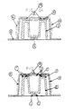
- Figures 1B and 2B illustrate another form of a conventional reinforcement
- Figure 1B shows the system prior to activation of the expandable adhesive material
- Figure 2B shows the system after activation.
- Figure 5A illustrates the potential deformation of the reinforcing system of Figure 2A when subject to a force in the direction showing by arrow 'A' and Figure 5B illustrates the potential deformation of the system of Figure 4A when subjected to the same force.
- Figure 6A illustrates the potential deformation of the reinforcing system of Figure 2B when subject to a force in the direction shown by arrow 'A' and Figure 6B illustrates the potential deformation of the reinforcing system of Figure 4B when subjected to the same force.
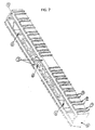
- Figure 7 shows a moulded structural reinforcing member provided with a plurality of pairs of ribs between which the expandable adhesive material may be located.
- Figure 1A shows a cross section of a hollow vehicle structural member (4) in which is positioned a reinforcing member (2) with an 'M' shaped cross section for example at XX' on Figure 7B.
- An expandable adhesive material (3) is provided on the surface of (2) adjacent the inner surface of the structural member (4).
- Figure 2A shows the same cross section as Figure 1A but after expansion of the expandable adhesive (3) as may be accomplished by the curing step in the electrocoat process.
- Figure 2A shows how the adhesive (3) expands between the reinforcing member (2) and the structural member (4) to provide a foam which bonds the reinforcing member and the structural member together.
- Figure 3A shows the same cross section of the hollow vehicle structural member (4) containing an 'M' shaped reinforcing member (2).
- the reinforcing member is provided with a pair of ribs (1) at the three positions where the expandable adhesive is provided. These pairs of ribs form grooves which contain the expandable adhesive (3).
- Figure 4A shows how the expansion of the expandable adhesive is controlled by the ribs (1) to enable adequate adhesion between the structural member (2) and the reinforcing member (4) with a smaller amount of expandable adhesive than that required in the system of Figure 1A.
- Comparison of Figures 5A and 5B show how the provision of the ribs (1) on the reinforcing member (2) (as in Figure 5B) reduces the deformation of the reinforced structure when compared to the deformation of the system without the ribs of this invention which is shown in Figure 5A.
- Figures 1B and 2B show an automobile structural member (4) of similar cross section to that in the previous figures.
- the structural member contains a 'U' shaped reinforcing member (2).
- the structural reinforcing member (2) is provided with expandable adhesive (3) at the corners of the 'U' shape.
- Figure 2B shows how the expandable adhesive can expand across the cavity between the structural member (4) and the reinforcing member (2) in order to bond the two together.
- Figures 6A and 6B show the deformation of the structural member (4) which occurs when the systems illustrated in Figure 2B and Figure 4B respectively are subjected to the same compression strength in the direction of the arrow A.
- Figure 7 shows a reinforcing member moulded from glass reinforced nylon employing the system illustrated in Figures 1B and 2B.
- the member consists of a structural reinforced component (5) provided with a labyrinth of reinforcing internal ribs (6).
- a series of pairs of ribs (7, 7); (8, 8); (9, 9) etc are moulded into the external surface of the moulding.
- Expandable adhesive material (not shown) may then be deposited in the grooves formed between the pairs of ribs according to the present invention the expandable adhesive material may also be located in channels 10 so that its expansion in a transverse direction is controlled by the ribs as shown by reference 3 in Figure 4A.
- the moulding may then be used to provide structural reinforcement within a vehicle sub frame in the manner described herein.
- the invention accordingly provides both ribbed mouldings containing unfoamed expandable adhesive and the reinforced hollow member containing the ribbed moulding bonded to the internal surface of the hollow structural member by the expanded adhesive.
- systems of the present invention enable improved or comparable reinforcement to be achieved whilst using a smaller amount of expandable adhesive material.
Abstract
Description
- The present invention relates to reinforcing materials and in particular to reinforcing materials that can be provided in hollow cross-sectional members particularly to provide reinforcement to improve the structural integrity of vehicles. The invention further provides a system whereby reinforcement can be provided whilst ensuring effective provision of an anti-corrosion coating on the inner surface of the hollow cross-sectional member by the electrocoat process. The electrocoat process used in vehicle manufacture is a process in which the vehicle structure is passed through a bath of anticorrosion fluid and the vehicle structure is used as an electrode whereby an anticorrosion coating is deposited from the fluid onto the vehicle structure by electrolysis. The coating is then baked by heating.
- The trends in motor vehicle design are towards lighter vehicles to improve fuel consumption. At the same time the safety standards and requirements are becoming more rigorous as indicated by the European Union requirements and the Euro-NCAP impact testing. The use of lighter materials such as aluminum to produce the hollow cross-sectional members that are used as vehicle sub frames has lead to the need for additional reinforcement. There is a need for reinforcement in various locations in the vehicle structure including the sub frame and upper structure, the form of reinforcement required can vary from one location in the vehicle to another and from vehicle to vehicle. The present invention therefore improves the strength of vehicles structures made from existing materials and enables vehicle structures based on lighter materials to contribute to safety requirements.
- There are five main types of application where structural reinforcement is required in vehicles. Crash protection where the prevention of vehicle body deformation is important to provide protection for the occupants. Energy absorption to enhance performance after yield. The reduction of mechanical constraints such as compression, shear torsion and flexing, or body movement in the vehicle structure particularly to improve durability and reduce stress cracking and the point mobility problems requiring the reduction of resonance by the provision of stiffening. The need for reinforcement is present irrespective of the materials that are used to produce the vehicle structure and the need varies from material to material and according to the nature of the reinforcement that is being provided. The reinforcing parts can also reduce the noise created by the motion of a vehicle by providing a sound deadening effect as a result of blocking air paths in cavities.
- It is known to provide foamable plastic mouldings within hollow cross sections of vehicles which can be foamed upon application of heat, such as is provided by the curing step in the electrocoat process, to provide a foamed baffle that fills the cross-section to provide sound adsorption. Such systems are described in European patent applications EP-0383498 and EP-0611778. The foam baffle provides sound deadening and vibration resistance. In these systems the entire insert is foamable and it is proposed that the foamable material be chosen so that it will foam during the curing process, which follows the electrocoat process typically used in vehicle manufacture to provide resistance to metal corrosion. The materials of these patents are not however reinforcing materials but are used to provide acoustic baffles and seals.
- In the electrocoat process a vehicle structure is immersed in a bath of coating fluid from which an anticorrosion coating is deposited on the metal by electrolysis. The vehicle metal structure is subsequently heated to bake the coating on the metal. The electrocoat process is typically applied to complete vehicle structures in which hollow sections have been capped. Accordingly reinforcing structures are preferably provided within hollow sections prior to the electrocoat. It is therefore important that the reinforcing structure have minimal impact on the operation and efficiency of the electrocoat process.
- Where reinforcing materials have been provided they have either been stuck to the metal structure prior to subjecting the vehicle structure to the electrocoat process or have been provided after the electrocoat process. The former technique has the problem that it is not possible to perform the electrocoat over the entire surface, which can lead to local areas of corrosion. The latter technique is cumbersome and requires the provision of fastening means after electrocoating, which can damage the electrocoat and again lead to local areas of corrosion.
- It is also known to provide structural reinforcement inside the structural members of automobile frames by the provision of metallic or plastic reinforcing members that are bonded to the inner surface of the structural member by means of a structural foam. For example, PCT Publications WO 99/61280 and WO 97/43501 disclosing 2 structural reinforcing member according the preamble of
claim 1. European Publication 1122152 and United States Patent 6092864 disclose metallic reinforcing members bonded to the internal surface of an automobile structural member by a structural foam and our co-pending UK Application 0106911.1 and US Applications 09/676335 and 09/502686 disclose moulded plastic, particularly glass reinforced nylon mouldings bonded to the internal surface of an automobile structure by a structural foam. - In the production of these reinforced structural members the metallic or moulded member is coated with an expandable adhesive material. The expandable adhesive material being such that it will expand at temperatures to which the automobile is exposed during manufacture such as in the curing stage of the electrocoat process or in the paint oven. The reinforcing member is therefore placed within the cavity of the vehicle with the coating of the expandable adhesive material being in an unfoamed state. During the automobile manufacture the expandable adhesive material will be brought to its expansion temperature and will expand to fill the gap between the inner surface of the vehicle structural member and the reinforcing member to bond the reinforcing member to the inner surface of the vehicle structural member. In this way a light and strong structural reinforcement is provided.
- Despite these techniques there is a continuing need to provide greater reinforcement and at the same time provide lighter weight vehicles, which in turn requires lighter weight reinforcing members. Accordingly, there is a need to reduce the weight and thus the amount of material used in the reinforcing members. Furthermore, there is an economic need to reduce the amount of expandable adhesive material that is used, consistent with achieving the desired degree of reinforcement.
- The present invention is aimed at providing such improved structural reinforcement systems.
- The present invention therefore provides a structural reinforcing member for reinforcing a hollow structural
member according claim 1. - The provision of the extensions on the mouldings according to the present invention can serve a dual function. Some or all of the extensions can provide local areas of the reinforcing member which when in place are closer to the inner surface of the hollow structural member than the remaining bulk of the reinforcing member. In this way the extensions may be located and designed to reduce deformation of the hollow structural member on impact. At least one, preferably at least two, of the pairs of extensions also direct the expansion of the expandable adhesive material to ensure that there is adhesion between the reinforcing member and the internal surface of the structural member where adhesion is required. This in turn enables selective use of the expandable adhesive material and can obviate the need to coat the entire surfaces of the reinforcing member that face the internal surfaces of the hollow structural member with the expandable adhesive material.
- The dimensions of the rigid reinforcing member and the thickness and nature of the expandable adhesive material are important to the achievement of the desired structural reinforcement. The exterior shape of the reinforcing member preferably conforms substantially to the cross section of the hollow structural member it is designed to reinforce. The shape may vary along the length of the reinforcing member as the dimensions of the cross section of the hollow structural member change. The size of the reinforcing member including the expandable adhesive material should be such that there is a small clearance between the extremity of the reinforcing member and the interior walls of the hollow structural member to allow for passage of the electrocoat fluid. We also prefer that the reinforcing member have a cellular, honeycomb or ribbed internal structure to provide reinforcement along several different axes at minimum weight.
- The extensions that are provided on the external surface of the structural reinforcing member may be ribs, raised embossments or they may be part of a stamped area.
- The extensions may be integral with a moulding if the parts are produced by injection moulding or may be stamped or otherwise formed on metal reinforcing members. Alternatively, and less preferred the extensions may be attached subsequent to the formation of the reinforcing member. The positioning of the extensions on the external surface of the reinforcing member will be determined by the shape of the member and the position in which it is to be placed within the hollow structural member which may be determined by the nature of the impact deformation that the reinforcing member is required to resist.
- In a preferred embodiment the structural reinforcing member is also provided with small lugs, which enable it to stand away from the interior walls of the hollow structural member. In this way fastening devices are not required and the area of contact between the structural reinforcing member and the interior walls of the hollow structural member is minimised. In this preferred embodiment the clearance between the extremity of the foamable adhesive material on the reinforcing member and the interior walls of the structural member can be determined to be wide enough to enable the liquid used in the electrocoat bath to flow between the reinforcing member and the interior walls of the hollow structural member in sufficient quantity to enable an effective anti-corrosion coating to be deposited. On the other hand, the clearance can be determined so as not be too wide since this can result in a lack of rigidity in the structure when the expandable adhesive has expanded to fill the clearance and bond the structural reinforcing member to the interior walls of the structural member. We prefer that the clearance be no more than 1 centimeter and is more preferably 2 to 10 millimeters, preferably 3 to 7 millimeters. A uniform clearance around the whole structure enables a more uniform foam structure to be obtained.
- The rigid reinforcing member may be made from any suitable material, for example it may be made of metal or plastic and the material will be chosen according to the preferred fabrication method. The plastic may be thermoplastic or thermosetting. This in turn is driven by economics and the complexity of the cross section to be reinforced. Reinforcing members for simple cross sections may be prepared by extrusion whilst injection moulding may be required for more complex structures. Metal members may be produced by stamping and/or forming. Where extrusion is used the members may be of metal or thermoplastics; where injection moulding is used thermoplastics are preferred, where compression moulding is used thermoplastic or thermosetting material may be used. Polyamides, particularly glass filled or carbon fibre filled polyamides are suitable materials particularly for injection mouldings due to their high strength to weight ratio. Alternatively injection moulding or die casting of metal alloys may be employed. It is preferred that the moulding is provided with means enabling fluid drainage. For example, holes or channels may be provided in the moulding to allow the drainage of water, which may condense in the structure over time.
- The invention is particularly useful for the provision of reinforcement in vehicles, particularly to provide crash resistance. The preferred shape and structure of the reinforcing member will depend upon where it is to be located in the vehicle structure and the function it is to perform. For example, if it is to be located in the front longitudinal section of the vehicle it will be designed for crash or impact resistance. On the other hand, it may be designed to reduce point mobility such as for example at the base of side and rear pillars in the vehicle. The reduction of point mobility is particularly important with high-sided vehicles where the reinforcement can reduce or prevent vehicle sway thus reducing metal fatigue. Other applications include the resistance of deformation of the rear longitudinal section, in particular to prevent upward deformation from rear impact, which can prevent the doors from being opened. Other parts of a vehicle which may be reinforced by the techniques of the present invention include roof structures, pillars, frame cross members such as the engine cradle and window frames particularly rear window frames.
- The expandable adhesive material serves two main functions, it will expand to fill the space between the reinforcing member and the interior of the hollow member and it will also bond to the interior wall of the hollow member. Accordingly, expandable adhesive material means that the material can be activated to both expand (typically foam) and to act as an adhesive, generally it acts as an adhesive at the conditions, usually temperatures, at which it expands. Activation therefore enables the expandable material to expand and fill a gap between the reinforcing member and the hollow structural member it is designed to reinforce and to bond to the internal surface of the hollow structure. Accordingly the expandable adhesive must expand at the desired temperature and be sufficiently adhesive to firmly bond the reinforcing member to the interior surface of the hollow structural member. The expanded product should be sufficiently strong that it does not contribute any weakness to the overall reinforcing effect provided.
- Whilst it is not essential it is preferred that prior to activation, the expandable adhesive material is dry and not tacky to the touch. It is preferred that the expandable material is not tacky to the touch since this facilitates shipping and handling of the structural reinforcing member and prevents contamination. Examples of preferred expandable adhesive materials include foamable epoxy-base resins and examples of such materials are the products L5206, L5207, L5208 and L5209, which are commercially available from L & L Products of Romeo Michigan USA, and the Betacore Products BC 5204, 5206, 5207, 5208 and 5214 available from Core Products, Strasbourg, France. The expandable adhesive material should be chosen according to the rate of expansion and foam densities required. It is further preferred that it expand at the temperatures experienced in the electrocoat oven, typically 130°C-200°C. Alternatively the material may be expanded by infrared high frequency, microwave or induction heating which are particularly useful in systems which do not employ the electrocoat process.
- The expandable adhesive material is applied to the surface of the reinforcing member at locations where its direction of expansion is controlled by at least two pairs of the extensions formed on the surface of the reinforcing member. In a preferred embodiment the reinforcing member is provided with two or more sets of pairs of ribs and the expandable adhesive material is provided between the ribs in the sets. In this way the reinforcing member may be located within the hollow structural member so that the extremities of the ribs are close to the inner surface of the hollow structural member so increasing the resistance to deformation of the hollow structural member. At the same time pairs of the ribs direct the expansion of the expandable adhesive material through the channel formed between the ribs towards the inner surface of the hollow structural member. In this way an effective bond between the rigid reinforcing member and the hollow structural member may be achieved with a reduced amount of expandable adhesive material since it is not necessary that the expandable material cover the entire surface of the reinforcing member.
- In a preferred embodiment a series of pairs of ribs may be provided along one or more of the surfaces of the reinforcing member and the expandable adhesive material may be located between the ribs of one or more pairs. In this way upon expansion bonds may be formed between the reinforcing member and the inner surface of the hollow structural member at different positions along the length and/or width of the reinforcing member. The preferred number of bond points and their location will depend on the size and shape of the reinforcing member and the forces which it is designed to withstand.
- In yet a further embodiment a single extension may be provided and the expandable material located close to the single extension so that its expansion in one direction is controlled by the extension. In this embodiment the size and shape of the cavity between the hollow structural member and the reinforcing member may be such that it controls the expansion of the expandable adhesive material in another direction.
- The expandable adhesive material should be applied to at least a portion of the surface of the rigid reinforcing member that will be adjacent to an interior surface of the hollow structure that is to be reinforced. This optimum location of the expandable adhesive will depend upon the shape of the hollow structure to be reinforced but it is preferably present so that it provides adhesion to two non-parallel surfaces to give rigidity in at least two dimensions. It is preferred that the expandable adhesive material be applied over at least part of each of the top and bottom and the sides of the reinforcing member. In this way when the material expands it can expand into the gap around the entire surface of the reinforcing member that is adjacent to the interior walls of the hollow structure. The expandable adhesive material may be applied to the rigid reinforcing member by bonding a strip of the material to the member, by for example extrusion coating or by injection moulding. Where the reinforcing member is made by injection moulding the expandable adhesive material may be applied by over-moulding or two shot injection moulding. The material should however be applied under conditions such that no expansion takes place.
- It is preferred that the reinforcing member with the expandable adhesive material thereon is located within the hollow structural member that it is designed to reinforce in a manner that provides a clearance between the external surface of the coated member and the internal surface of the hollow structural member. This allows for the passage of the electrocoat fluid between the hollow structural member and the internal surface and also enables a uniform expansion of the foam around the member to provide more uniform reinforcement.
- Accordingly in a preferred process for providing reinforcement within a hollow structural member such as a vehicle frame, moulded reinforcing members provided with pairs of extensions and with a layer of expandable adhesive material thereon between the extensions that make up the pair extensions are installed during assembly of the vehicle frame. Locating lugs are preferably moulded into the reinforcing member or the expandable adhesive material so that the reinforcing member sits within the hollow structural member leaving a space between the member and the interior walls of the hollow structural member to be reinforced, in this way there is no need for fastening or bonding means to attach the member to the interior walls of the hollow structural member. The assembled structure is then subjected to the electrocoat process in which it is passed through a bath of coating material and a corrosion resistant coating is deposited onto the structure by electrolysis. The vehicle structure is then dried in an oven to cure the coating; the expandable adhesive is preferably chosen so that it is activated to expand and develop adhesive properties by the conditions used in the oven employed to cure the coating. The expandable adhesive material will therefore expand under the curing conditions to provide both a foam that fills the space between the member and the interior walls of the hollow structural member and a strong bond between the reinforcing member and the interior wall of the hollow structural member. Typically the coated structure is cured at around 165°C for about 20 minutes and accordingly the expandable adhesive material should be activated under these conditions. The automobile industry is however looking to use lower curing temperatures and shorter drying times and this may influence the choice of expandable adhesive materials.
- If other components for example bolts are to pass through the reinforcing members during subsequent assembly if may be necessary to take care to ensure that holes formed in the reinforcing member for the passage of the bolts are not blocked by the expansion of the expandable adhesive material.
- The techniques of the present invention may be used for the reinforcement of any construction that is based on a hollow frame structure. They may for instance be used in the construction industry, in boats, in aircraft, and in railroad applications. The techniques are however particularly useful to provide reinforcement in automobiles including cars, trucks, buses, caravans and the like. The techniques are particularly useful in the current trend towards using lighter and sometimes weaker materials in the production of automobile sub frames where there is a greater need for reinforcement to compensate for the reduction in strength of the basic material and contribute to satisfy the safety requirements. This is particularly the case with the use of aluminum for the production of hollow sub frames of automobiles.
- The present invention is illustrated by reference to the accompanying drawings in which Figures 1A and 2A illustrate a reinforcement according to the prior art, Figure 1A shows the system prior to activation of the expandable adhesive material and Figure 2A shows the system after activation.
- Figures 3A and 4A illustrate a reinforcement according to the present invention. Figure 3A shows the system prior to activation of the expandable adhesive material and Figure 4A shows the system after activation.
- Figures 1B and 2B illustrate another form of a conventional reinforcement, Figure 1B shows the system prior to activation of the expandable adhesive material and Figure 2B shows the system after activation.
- Figure 5A illustrates the potential deformation of the reinforcing system of Figure 2A when subject to a force in the direction showing by arrow 'A' and Figure 5B illustrates the potential deformation of the system of Figure 4A when subjected to the same force.
- Figure 6A illustrates the potential deformation of the reinforcing system of Figure 2B when subject to a force in the direction shown by arrow 'A' and Figure 6B illustrates the potential deformation of the reinforcing system of Figure 4B when subjected to the same force.
- Figure 7 shows a moulded structural reinforcing member provided with a plurality of pairs of ribs between which the expandable adhesive material may be located.
- Figure 1A shows a cross section of a hollow vehicle structural member (4) in which is positioned a reinforcing member (2) with an 'M' shaped cross section for example at XX' on Figure 7B. An expandable adhesive material (3) is provided on the surface of (2) adjacent the inner surface of the structural member (4). Figure 2A shows the same cross section as Figure 1A but after expansion of the expandable adhesive (3) as may be accomplished by the curing step in the electrocoat process. Figure 2A shows how the adhesive (3) expands between the reinforcing member (2) and the structural member (4) to provide a foam which bonds the reinforcing member and the structural member together.
- Figure 3A shows the same cross section of the hollow vehicle structural member (4) containing an 'M' shaped reinforcing member (2). In this instance the reinforcing member is provided with a pair of ribs (1) at the three positions where the expandable adhesive is provided. These pairs of ribs form grooves which contain the expandable adhesive (3). Figure 4A shows how the expansion of the expandable adhesive is controlled by the ribs (1) to enable adequate adhesion between the structural member (2) and the reinforcing member (4) with a smaller amount of expandable adhesive than that required in the system of Figure 1A. Comparison of Figures 5A and 5B show how the provision of the ribs (1) on the reinforcing member (2) (as in Figure 5B) reduces the deformation of the reinforced structure when compared to the deformation of the system without the ribs of this invention which is shown in Figure 5A.
- Figures 1B and 2B show an automobile structural member (4) of similar cross section to that in the previous figures. In this instance the structural member contains a 'U' shaped reinforcing member (2). In Figure 1B the structural reinforcing member (2) is provided with expandable adhesive (3) at the corners of the 'U' shape. Figure 2B shows how the expandable adhesive can expand across the cavity between the structural member (4) and the reinforcing member (2) in order to bond the two together.
- Figures 6A and 6B, show the deformation of the structural member (4) which occurs when the systems illustrated in Figure 2B and Figure 4B respectively are subjected to the same compression strength in the direction of the arrow A.
- Figure 7 shows a reinforcing member moulded from glass reinforced nylon employing the system illustrated in Figures 1B and 2B. The member consists of a structural reinforced component (5) provided with a labyrinth of reinforcing internal ribs (6). A series of pairs of ribs (7, 7); (8, 8); (9, 9) etc are moulded into the external surface of the moulding. Expandable adhesive material (not shown) may then be deposited in the grooves formed between the pairs of ribs according to the present invention the expandable adhesive material may also be located in channels 10 so that its expansion in a transverse direction is controlled by the ribs as shown by
reference 3 in Figure 4A. The moulding may then be used to provide structural reinforcement within a vehicle sub frame in the manner described herein. - The invention accordingly provides both ribbed mouldings containing unfoamed expandable adhesive and the reinforced hollow member containing the ribbed moulding bonded to the internal surface of the hollow structural member by the expanded adhesive.
- As illustrated the systems of the present invention enable improved or comparable reinforcement to be achieved whilst using a smaller amount of expandable adhesive material.
Claims (28)
- A structural reinforcing member for reinforcing a hollow structural member (4), comprising a reinforcing member (2) having on a portion of the surface thereof an expandable adhesive material (3) characterized in that the surface of the reinforcing member (2) is provided with two or more pairs of extensions (1) which approach the internal surface of the hollow structural member (4) when the reinforcing member (2) is placed within the hollow structural member (4), wherein the surface of the reinforcing member (2) between at least two of said pairs of extensions has no expandable adhesive material thereon and expandable adhesive material (3) is located within at least two of said pairs of extensions such that the extensions within which the expandable adhesive material (3) is located guide the expansion of the expandable adhesive material (3).
- A structural reinforcing member according to Claim 1, in which the exterior shape of the reinforcing member (2) conforms substantially to the cross section of the hollow structural member (4).
- A structural reinforcing member according to Claim 1 or Claim 2, in which the size of the reinforcing member (2) including the expandable adhesive material (3) is such that there is a small clearance between the extremity of the reinforcing member (2) and the interior walls of the hollow structural member (4).
- A structural reinforcing member according to any of the preceding Claims, in which the reinforcing member (2) has a cellular, honeycomb or ribbed internal structure.
- A structural reinforcing member according to any of the preceding Claims, in which the extensions (1) are ribs, raised embossments or are part of a stamped area.
- A structural reinforcing member according to any of the preceding Claims in which the extensions (1) are integral with the reinforcing member.
- A structural reinforcing member according to any of the preceding Claims, provided with small lugs which enable the structural reinforcing member to stand away from the interior walls of the hollow structural member (4).
- A structural reinforcing member according to any of Claims 3 to 7 in which the clearance is no more than 1 centimeter.
- A structural reinforcing member according to any of the preceding Claims made from filled polyamide.
- A structural reinforcing member according to Claim 9 in which the filler is glass fibre.
- A structural reinforcing member according to Claim 9 in which the filler is carbon fibre.
- A structural member according to any of Claims 1 to 8 made from a thermosetting resin.
- A structural reinforcing member according to any of the preceding Claims, in which the expandable adhesive material (3) can be activated to both expand and to act as an adhesive when heated.
- A structural reinforcing member according to Claim 13, in which the expandable adhesive material (3) can be activated at the temperature of the curing step in the electrocoat process.
- A structural reinforcing member according to any of the preceding Claims, in which prior to activation, the expandable adhesive material (3) is dry to the touch.
- A structural reinforcing member according to any of the preceding Claims, in which the expandable adhesive material (3) is a foamable epoxy-base resin.
- A structural reinforcing member according to any of the preceding Claims, in which the expandable adhesive material (3) is applied to at least a portion of the surfaces of the rigid reinforcing member that will be adjacent to two non-parallel surfaces of the interior surface of the hollow structural member (4).
- A structural reinforcing member according to Claim 17, in which the expandable adhesive material (3) is applied over part of each of the top and bottom and the sides of the reinforcing member (2).
- A structural reinforcing member according to any of the preceding Claims, in which a series of pairs of ribs (7, 8, 9) are provided along one or more of the surfaces of the reinforcing member (2).
- The use of a structural reinforcing member according to any of the preceding Claims to provide reinforcement in a vehicle.
- The use according to Claim 20 to reduce point mobility.
- The use according to Claim 20 to provide reinforcement of the front longitudinal section of a vehicle.
- The use according to Claim 20 to provide resistance of deformation of the rear longitudinal section.
- The use according to Claim 20 to reinforce pillars, frame cross members and window frames.
- A process for providing reinforcement within hollow structures in which a structural reinforcing member according to any of Claims 1 to 19 is installed during assembly of a vehicle frame, and the system is heated whereby the expandable adhesive material expands to provide a foam between the structural reinforcing member and the interior walls of the hollow structural member and bonds the structural reinforcing member to the interior wall of the structural hollow member.
- A process according to Claim 25 in which the heating takes place in the electrocoating curing process.
- A process according to Claim 26 in which the heating is by infrared, high frequency, microwave or induction heating.
- A process according to any of Claims 25 to 27 in which the heating is between 130°C and 200°C.
Applications Claiming Priority (3)
| Application Number | Priority Date | Filing Date | Title |
|---|---|---|---|
| GB0111151 | 2001-05-08 | ||
| GB0111151A GB2375328A (en) | 2001-05-08 | 2001-05-08 | Reinforcing element for hollow structural member |
| PCT/EP2002/005224 WO2003000535A1 (en) | 2001-05-08 | 2002-05-07 | Improved structural reinforcement |
Publications (2)
| Publication Number | Publication Date |
|---|---|
| EP1387789A1 EP1387789A1 (en) | 2004-02-11 |
| EP1387789B1 true EP1387789B1 (en) | 2006-09-13 |
Family
ID=9914172
Family Applications (1)
| Application Number | Title | Priority Date | Filing Date |
|---|---|---|---|
| EP02750918A Expired - Lifetime EP1387789B1 (en) | 2001-05-08 | 2002-05-07 | Improved structural reinforcement |
Country Status (8)
| Country | Link |
|---|---|
| US (2) | US6941719B2 (en) |
| EP (1) | EP1387789B1 (en) |
| AT (1) | ATE339344T1 (en) |
| CA (1) | CA2442544A1 (en) |
| DE (1) | DE60214699T2 (en) |
| ES (1) | ES2272743T3 (en) |
| GB (1) | GB2375328A (en) |
| WO (1) | WO2003000535A1 (en) |
Cited By (4)
| Publication number | Priority date | Publication date | Assignee | Title |
|---|---|---|---|---|
| WO2010128064A1 (en) * | 2009-05-05 | 2010-11-11 | Sika Technology Ag | Bonding with adhesive beads or plots |
| KR20110050692A (en) * | 2008-09-01 | 2011-05-16 | 시카 테크놀러지 아게 | Bonding with adhesive beads or plots |
| WO2021038156A1 (en) | 2019-08-23 | 2021-03-04 | Psa Automobiles Sa | Reinforcement for a hollow body |
| DE102013114108B4 (en) | 2013-12-16 | 2022-12-08 | Dr. Ing. H.C. F. Porsche Aktiengesellschaft | Vehicle pillar with a reinforcement part |
Families Citing this family (127)
| Publication number | Priority date | Publication date | Assignee | Title |
|---|---|---|---|---|
| US6482486B1 (en) | 2000-03-14 | 2002-11-19 | L&L Products | Heat activated reinforcing sleeve |
| US6820923B1 (en) | 2000-08-03 | 2004-11-23 | L&L Products | Sound absorption system for automotive vehicles |
| GB0106911D0 (en) | 2001-03-20 | 2001-05-09 | L & L Products | Structural foam |
| GB2375328A (en) | 2001-05-08 | 2002-11-13 | L & L Products | Reinforcing element for hollow structural member |
| US6729425B2 (en) | 2001-09-05 | 2004-05-04 | L&L Products, Inc. | Adjustable reinforced structural assembly and method of use therefor |
| US6786533B2 (en) | 2001-09-24 | 2004-09-07 | L&L Products, Inc. | Structural reinforcement system having modular segmented characteristics |
| US6793274B2 (en) | 2001-11-14 | 2004-09-21 | L&L Products, Inc. | Automotive rail/frame energy management system |
| WO2003061934A1 (en) | 2002-01-22 | 2003-07-31 | Dow Global Technologies Inc. | Reinforced structural body and manufacturing method therefor |
| US7318873B2 (en) | 2002-03-29 | 2008-01-15 | Zephyros, Inc. | Structurally reinforced members |
| CA2482168A1 (en) | 2002-04-15 | 2003-10-30 | Dow Global Technologies Inc. | Improved vehicular structural members and method of making the members |
| US7077460B2 (en) | 2002-04-30 | 2006-07-18 | L&L Products, Inc. | Reinforcement system utilizing a hollow carrier |
| US20040018353A1 (en) * | 2002-07-25 | 2004-01-29 | L&L Products, Inc. | Composite metal foam damping/reinforcement structure |
| US6883858B2 (en) * | 2002-09-10 | 2005-04-26 | L & L Products, Inc. | Structural reinforcement member and method of use therefor |
| US7105112B2 (en) * | 2002-11-05 | 2006-09-12 | L&L Products, Inc. | Lightweight member for reinforcing, sealing or baffling |
| US7313865B2 (en) * | 2003-01-28 | 2008-01-01 | Zephyros, Inc. | Process of forming a baffling, sealing or reinforcement member with thermoset carrier member |
| US8156711B2 (en) * | 2003-02-24 | 2012-04-17 | Bell Helicopter Textron Inc. | Contact stiffeners for structural skins |
| GB2401349A (en) * | 2003-05-08 | 2004-11-10 | L & L Products | Reinforcement for a vehicle panel |
| US7249415B2 (en) | 2003-06-26 | 2007-07-31 | Zephyros, Inc. | Method of forming members for sealing or baffling |
| US7479245B2 (en) | 2003-06-26 | 2009-01-20 | Zephyros, Inc. | Process for applying a material to a member |
| US7784186B2 (en) | 2003-06-26 | 2010-08-31 | Zephyros, Inc. | Method of forming a fastenable member for sealing, baffling or reinforcing |
| GB2415162A (en) * | 2004-06-15 | 2005-12-21 | L & L Products Inc | Improvements in or relating to laminar mouldings |
| US20060005503A1 (en) * | 2004-07-07 | 2006-01-12 | Jeffrey Bladow | Reinforced structural member and method for its manufacture |
| US20050012280A1 (en) * | 2004-08-13 | 2005-01-20 | L&L Products, Inc. | Sealing member, sealing method and system formed therewith |
| US7374219B2 (en) | 2004-09-22 | 2008-05-20 | Zephyros, Inc. | Structural reinforcement member and method of use therefor |
| US7526900B2 (en) * | 2004-11-23 | 2009-05-05 | Benjamin Obdyke Incorporated | Masonry cavity wall having a compressible, expandable debris blocker |
| US7621373B2 (en) * | 2004-12-15 | 2009-11-24 | Sika Technology Ag | Acoustic drain |
| GB2421478A (en) | 2004-12-21 | 2006-06-28 | L & L Products Inc | Vehicle structure reinforcement member |
| GB0506404D0 (en) * | 2005-03-30 | 2005-05-04 | L & L Products Inc | Improvements in or relating to components |
| US20070080559A1 (en) * | 2005-04-28 | 2007-04-12 | L&L Products, Inc. | Member for baffling, reinforcement of sealing |
| US7926179B2 (en) | 2005-08-04 | 2011-04-19 | Zephyros, Inc. | Reinforcements, baffles and seals with malleable carriers |
| DE102005057707B4 (en) * | 2005-12-02 | 2014-01-02 | Audi Ag | A-pillar for a motor vehicle |
| US8087916B2 (en) * | 2005-12-15 | 2012-01-03 | Cemedine Henkel Co., Ltd. | Holding jig for a foamable material |
| GB0600901D0 (en) * | 2006-01-17 | 2006-02-22 | L & L Products Inc | Improvements in or relating to reinforcement of hollow profiles |
| FR2897335B1 (en) * | 2006-02-13 | 2009-04-03 | Peugeot Citroen Automobiles Sa | METHOD FOR ASSEMBLING PARTS OF A MOTOR VEHICLE |
| US20070200047A1 (en) * | 2006-02-21 | 2007-08-30 | Steven Rosenberg | Expandable reinforcing member |
| DE102006015914B4 (en) * | 2006-04-05 | 2019-01-17 | Ford Global Technologies, Llc | bumper system |
| DE102006032472B4 (en) * | 2006-07-13 | 2013-11-14 | Audi Ag | Body for a convertible vehicle |
| US7913467B2 (en) * | 2006-07-25 | 2011-03-29 | Zephyros, Inc. | Structural reinforcements |
| EP1930231B1 (en) | 2006-12-05 | 2009-04-22 | Henkel AG & Co. KGaA | Reinforcing component |
| EP1932648A1 (en) † | 2006-12-15 | 2008-06-18 | Sika Technology AG | Structural reinforcement material, insert, and reinforced cavity comprising same |
| EP1946995A1 (en) * | 2006-12-22 | 2008-07-23 | Sika Technology AG | Reinforcing system for reinforcing a cavity in a structural element |
| US7673930B2 (en) * | 2006-12-22 | 2010-03-09 | Sika Technology Ag | RT reinforcer |
| US8002332B2 (en) | 2007-01-30 | 2011-08-23 | Zephyros, Inc. | Structural mounting insert |
| US20080296164A1 (en) * | 2007-06-02 | 2008-12-04 | Lanxess Deutschland Gmbh | Reinforcement Element for a Vehicle Hollow Body |
| DE102007053961A1 (en) * | 2007-07-18 | 2009-01-22 | Johnson Controls Gmbh | Structure for a vehicle seat |
| DE102007053962A1 (en) * | 2007-07-18 | 2009-01-22 | Johnson Controls Gmbh | Structure for vehicle seat |
| US7735906B2 (en) | 2007-09-28 | 2010-06-15 | Zephyros, Inc. | Reinforcement system for an automotive vehicle |
| US7641264B2 (en) * | 2007-10-05 | 2010-01-05 | Sika Technology, AG | Reinforcement device |
| US20090096251A1 (en) * | 2007-10-16 | 2009-04-16 | Sika Technology Ag | Securing mechanism |
| US8966766B2 (en) | 2007-10-25 | 2015-03-03 | Zephyros, Inc. | Reinforcement structure and method employing bulkheads |
| GB2455292A (en) * | 2007-12-03 | 2009-06-10 | Zephyros Inc | Improvements in or relating to the production of joints |
| US8020924B2 (en) | 2007-12-26 | 2011-09-20 | Sika Technology Ag | Integrated reinforcing crossmember |
| US7748773B2 (en) | 2007-12-31 | 2010-07-06 | Sika Technology Ag | Structural member reinforcement |
| US8181327B2 (en) | 2008-02-08 | 2012-05-22 | Zephyros, Inc | Mechanical method for improving bond joint strength |
| US9194408B2 (en) | 2008-02-08 | 2015-11-24 | Zephyros, Inc. | Mechanical method for improving bond joint strength |
| US8293360B2 (en) * | 2008-02-27 | 2012-10-23 | Sika Technology Ag | Baffle |
| US8133929B2 (en) * | 2008-04-15 | 2012-03-13 | Sika Technology Ag | Method for incorporating long glass fibers into epoxy-based reinforcing resins |
| KR20110028533A (en) * | 2008-07-02 | 2011-03-18 | 바스프 에스이 | Foamable polyamides |
| ES2579228T3 (en) | 2008-07-25 | 2016-08-08 | Sika Technology Ag | Interconnected foam or adhesive layers |
| WO2010017167A2 (en) * | 2008-08-04 | 2010-02-11 | Owens Corning Intellectual Capital, Llc | Insulation element for an electrical appliance such as a dishwasher |
| EP2154052A1 (en) | 2008-08-12 | 2010-02-17 | Sika Technology AG | Structural reinforcement system |
| EP2159109A1 (en) * | 2008-09-01 | 2010-03-03 | Sika Technology AG | Reinforcement with channel design |
| CN102227459B (en) | 2008-09-29 | 2014-01-15 | 巴斯夫欧洲公司 | Method for coating paper |
| KR101552752B1 (en) | 2008-11-07 | 2015-09-11 | 제피로스, 인크. | Hybrid reinforcement structure |
| US8691127B2 (en) * | 2008-12-19 | 2014-04-08 | Basf Se | Method for producing a composite component by multi-component injection molding |
| DE102009006444B4 (en) | 2009-01-28 | 2022-01-05 | Dr. Ing. H.C. F. Porsche Aktiengesellschaft | Device for supporting a bumper lining of a motor vehicle |
| EP2401191B1 (en) * | 2009-02-27 | 2013-04-10 | Sika Technology AG | Structural reinforcement system |
| US7984919B2 (en) * | 2009-05-18 | 2011-07-26 | Zephyros, Inc. | Structural mounting insert having a non-conductive isolator |
| CA2768476C (en) * | 2009-07-17 | 2018-11-06 | Patrick R. Clark | Co-extruded u-channel with integrated glassrun |
| EP2289771B2 (en) * | 2009-08-27 | 2017-10-11 | Sika Technology AG | Structural reinforcer with bonding material on orthoganal surfaces |
| EP2330019A1 (en) * | 2009-12-04 | 2011-06-08 | Sika Technology AG | Baffle reverse molding |
| CA2800210A1 (en) | 2010-05-21 | 2011-11-24 | Zephyros, Inc. | Method for application of structural materials |
| MX2013003211A (en) * | 2010-09-22 | 2013-08-27 | Basf Se | Plastic reinforced metallic roof bow. |
| DE102011000450A1 (en) * | 2011-02-02 | 2012-08-02 | Dr. Ing. H.C. F. Porsche Aktiengesellschaft | Support structure for producing e.g. A-pillar of vehicle, has expandable adhesive material between structural element and reinforcement element, which surrounds three sides of portion of reinforcement element facing auxiliary frame |
| WO2012125995A1 (en) | 2011-03-17 | 2012-09-20 | Zephyros, Inc. | Bonding assembly |
| US8474903B2 (en) * | 2011-04-29 | 2013-07-02 | Honda Motor Co., Ltd. | Serpentine section stabilizer for vehicle pillar |
| DE102011120125A1 (en) * | 2011-12-03 | 2013-06-06 | GM Global Technology Operations LLC (n. d. Gesetzen des Staates Delaware) | Connector for connecting structural element with wall element for motor vehicle, has punch rivet that partially penetrates structural element and wall element, where outer periphery of punch rivet is surrounded by adhesive layer |
| DE102011088286A1 (en) * | 2011-12-12 | 2013-06-13 | Bayerische Motoren Werke Aktiengesellschaft | Composite component and method for producing a composite component |
| GB201207481D0 (en) | 2012-04-26 | 2012-06-13 | Zephyros Inc | Applying flowable materials to synthetic substrates |
| MX2013013263A (en) | 2012-11-14 | 2014-10-01 | Zephyros Inc | Panel connector devices. |
| CN102995051B (en) * | 2012-11-20 | 2015-01-28 | 上海高企新能源科技有限公司 | Carbon fiber electrode frame and diaphragm for filter pressing type bi-electrode electrolysis cell |
| US8864216B2 (en) | 2013-01-18 | 2014-10-21 | Sabic Global Technologies B.V. | Reinforced body in white and method of making and using the same |
| US9033404B2 (en) * | 2013-03-14 | 2015-05-19 | Honda Motor Co., Ltd. | Encapsulated aluminum honeycomb structural stiffener |
| JP5924321B2 (en) * | 2013-08-27 | 2016-05-25 | トヨタ自動車株式会社 | Vehicle skeleton structure |
| DE102013218725A1 (en) * | 2013-09-18 | 2015-03-19 | Bayerische Motoren Werke Aktiengesellschaft | Vehicle body with an underbody structure and a subframe attached thereto |
| US10421260B2 (en) | 2013-12-17 | 2019-09-24 | Zephyros, Inc. | Carrier with localized fibrous insert and methods |
| GB201318595D0 (en) * | 2013-10-21 | 2013-12-04 | Zephyros Inc | Improvements in or relating to laminates |
| US9211664B2 (en) * | 2013-11-13 | 2015-12-15 | Honda Motor Co., Ltd. | Multi-piece acoustic spray foam control system and method |
| US9873469B2 (en) | 2013-11-22 | 2018-01-23 | Kyle R. Gillin | Flooring apparatus |
| EP2899100B1 (en) * | 2014-01-27 | 2018-06-27 | MAGNA STEYR Fahrzeugtechnik AG & Co KG | Bonded joint and bonding method of two hollow profiles |
| JP6036721B2 (en) * | 2014-02-06 | 2016-11-30 | マツダ株式会社 | Vehicle body structure |
| DE102014002612B3 (en) * | 2014-02-27 | 2015-08-06 | Imperia Gesellschaft für angewandte Fahrzeugentwicklung mbH | Method for producing a lightweight component and component set for use in a corresponding method |
| DE102015002262A1 (en) | 2014-02-27 | 2015-08-27 | Imperia Gesellschaft für angewandte Fahrzeugentwicklung mbH | Method for producing a lightweight component |
| WO2015157250A1 (en) | 2014-04-09 | 2015-10-15 | Honda Motor Co., Ltd. | Vehicle frame construction and method |
| WO2015193795A1 (en) | 2014-06-16 | 2015-12-23 | Sabic Global Technologies B.V. | Method of making a laminate, an energy absorbing device, an energy absorbing device composition, and a forming tool |
| US11198236B2 (en) * | 2014-11-14 | 2021-12-14 | Zephyros, Inc. | Multi-shot injection molded method and product |
| JP6109271B2 (en) * | 2015-02-06 | 2017-04-05 | 株式会社神戸製鋼所 | Junction structure and manufacturing method of junction structure |
| US9764769B2 (en) * | 2015-02-09 | 2017-09-19 | Honda Motor Co., Ltd. | Vehicle frame structural member assembly and method |
| US9758193B2 (en) | 2015-02-10 | 2017-09-12 | Honda Motor Co., Ltd. | Structural reinforcement member for a vehicle body |
| US9776664B2 (en) | 2015-03-18 | 2017-10-03 | Honda Motor Co., Ltd. | Impact transmission structure |
| US10457336B2 (en) * | 2015-09-10 | 2019-10-29 | Kyle R. Gillin | Flooring apparatus and methods of manufacture |
| JP6932926B2 (en) * | 2015-09-18 | 2021-09-08 | 東レ株式会社 | Housing |
| JP6728077B2 (en) * | 2016-05-20 | 2020-07-22 | 株式会社神戸製鋼所 | Structural member |
| EP3487749B1 (en) | 2016-07-21 | 2021-10-06 | Zephyros, Inc. | Reinforcement structure |
| US10173727B2 (en) | 2016-07-28 | 2019-01-08 | Zephyros, Inc. | Multiple stage deformation reinforcement structure for impact absorption |
| US9969442B1 (en) | 2016-12-16 | 2018-05-15 | Honda Motor Co., Ltd. | Vehicle body frame including structural bulkhead with acoustic spray foam control |
| JP2020504691A (en) | 2016-12-30 | 2020-02-13 | サビック グローバル テクノロジーズ ベスローテン フェンノートシャップ | Hybrid structure and manufacturing method thereof |
| EP3568336B1 (en) * | 2017-01-11 | 2021-08-11 | Zephyros, Inc. | Reinforcing devices |
| WO2018136969A1 (en) * | 2017-01-23 | 2018-07-26 | Zephyros, Inc. | Pillar reinforcement |
| EP3612436B1 (en) | 2017-04-21 | 2021-03-10 | Sika Technology AG | Reinforcing element |
| US11535307B2 (en) | 2017-06-22 | 2022-12-27 | Sika Technology Ag | Reinforcing element, system of a reinforced structural element and method for reinforcing a structural element |
| KR102556259B1 (en) | 2017-06-22 | 2023-07-14 | 시카 테크놀러지 아게 | Connection of car body elements |
| EP3421331B1 (en) | 2017-06-29 | 2021-06-16 | Sika Technology Ag | System of a reinforced structural element of a motor vehicle |
| US10214243B2 (en) * | 2017-07-11 | 2019-02-26 | Ford Global Technologies, Llc | Vehicle frame |
| EP3710341B1 (en) * | 2017-11-15 | 2022-01-12 | Sika Technology AG | Device for reinforcing, sealing or damping of a structural element |
| EP3710340B1 (en) | 2017-11-15 | 2022-06-29 | Sika Technology AG | Device for reinforcing a structural element |
| EP3486144B1 (en) * | 2017-11-15 | 2022-01-19 | Sika Technology Ag | System of a reinforced structural element of a motor vehicle |
| FR3076526B1 (en) * | 2018-01-11 | 2021-12-17 | Psa Automobiles Sa | VEHICLE PRESENTING A REINFORCEMENT PART TO SUPPORT A BODY PANEL |
| JP6676092B2 (en) * | 2018-03-28 | 2020-04-08 | 株式会社豊田自動織機 | Body reinforcing structure and method of manufacturing body reinforcing structure |
| WO2019222151A1 (en) | 2018-05-14 | 2019-11-21 | Magna International Inc. | Adhesively bonded joint |
| KR20210050513A (en) * | 2018-08-31 | 2021-05-07 | 시카 테크놀러지 아게 | Devices for reinforcing, sealing or damping structural elements |
| JP6950871B2 (en) * | 2019-01-23 | 2021-10-13 | Jfeスチール株式会社 | Body skeleton parts |
| DE102019109035A1 (en) * | 2019-04-05 | 2020-10-08 | Bayerische Motoren Werke Aktiengesellschaft | Stiffening element for a body of a motor vehicle and a body for a motor vehicle |
| US20220324197A1 (en) | 2019-09-27 | 2022-10-13 | Zephyros, Inc. | Room temperature foamed and cured carriers |
| KR20210087589A (en) * | 2020-01-02 | 2021-07-13 | 현대자동차주식회사 | Door for vehicle |
| EP3907123A1 (en) * | 2020-05-08 | 2021-11-10 | Sika Technology Ag | Reinforcement element for reinforcing a structural element |
| DE102021119368A1 (en) | 2021-07-27 | 2023-02-02 | Dr. Ing. H.C. F. Porsche Aktiengesellschaft | structural component |
Family Cites Families (209)
| Publication number | Priority date | Publication date | Assignee | Title |
|---|---|---|---|---|
| US502686A (en) | 1893-08-01 | Wheelock g | ||
| GB106911A (en) | ||||
| US676335A (en) | 1900-11-20 | 1901-06-11 | John F Schenck | Shell-holder for thread-winding machines. |
| US3400182A (en) | 1965-08-03 | 1968-09-03 | Budd Co | Method of interconnecting spaced panels and means for use therein |
| US3868796A (en) * | 1973-04-04 | 1975-03-04 | Ford Motor Co | Side door intrusion protection |
| US4352484A (en) | 1980-09-05 | 1982-10-05 | Energy Absorption Systems, Inc. | Shear action and compression energy absorber |
| US4610836A (en) * | 1983-09-12 | 1986-09-09 | General Motors Corporation | Method of reinforcing a structural member |
| US4732806A (en) * | 1983-09-12 | 1988-03-22 | General Motors Corporation | Structural member comprising glass macrospheres |
| US4695343A (en) * | 1983-09-12 | 1987-09-22 | General Motors Corporation | Method of reinforcing a structural member |
| US4463870A (en) * | 1983-10-19 | 1984-08-07 | L & L Products, Inc. | Closure plate for an opening |
| US4536541A (en) * | 1984-02-27 | 1985-08-20 | E. I. Du Pont De Nemours And Company | High impact resistant polyamide |
| DE3423827A1 (en) | 1984-06-04 | 1985-02-14 | Stübbe GmbH, 2940 Wilhemshaven | PLASTIC DOOR FOR MOTOR VEHICLES |
| US4751249A (en) * | 1985-12-19 | 1988-06-14 | Mpa Diversified Products Inc. | Reinforcement insert for a structural member and method of making and using the same |
| US4769391A (en) * | 1985-12-19 | 1988-09-06 | Essex Composite Systems | Reinforcement insert for a structural member and method of making and using the same |
| EP0236291B1 (en) | 1986-02-21 | 1991-04-17 | Austria Metall Aktiengesellschaft | Guard bar, especially for reinforcing of motor vehicle doors |
| US4861097A (en) * | 1987-09-18 | 1989-08-29 | Essex Composite Systems | Lightweight composite automotive door beam and method of manufacturing same |
| US4922596A (en) * | 1987-09-18 | 1990-05-08 | Essex Composite Systems | Method of manufacturing a lightweight composite automotive door beam |
| US4901500A (en) * | 1987-09-18 | 1990-02-20 | Essex Composite Systems | Lightweight composite beam |
| US4813690A (en) * | 1987-11-24 | 1989-03-21 | L & L Products, Inc. | Sealing member |
| US4923902A (en) * | 1988-03-10 | 1990-05-08 | Essex Composite Systems | Process and compositions for reinforcing structural members |
| US4995545A (en) * | 1988-03-10 | 1991-02-26 | Essex Composite Systems | Method of reinforcing a structure member |
| US4836516A (en) * | 1988-04-25 | 1989-06-06 | Essex Composite Systems | Filled tubular torsion bar and its method of manufacture |
| US4908930A (en) * | 1988-04-25 | 1990-03-20 | Essex Composite Systems | Method of making a torsion bar |
| US4853270A (en) * | 1988-06-27 | 1989-08-01 | Essex Specialty Products, Inc. | Knee blocker for automotive application |
| US4810548A (en) * | 1988-08-01 | 1989-03-07 | Ligon Brothers Manufacturing Company | Sandwich seal fixture |
| GB8903211D0 (en) | 1989-02-13 | 1989-03-30 | Exxon Chemical Patents Inc | Thermoplastic foamable compositions and car body inserts made from such composition |
| US4978562A (en) * | 1990-02-05 | 1990-12-18 | Mpa Diversified Products, Inc. | Composite tubular door beam reinforced with a syntactic foam core localized at the mid-span of the tube |
| US5124186A (en) * | 1990-02-05 | 1992-06-23 | Mpa Diversified Products Co. | Composite tubular door beam reinforced with a reacted core localized at the mid-span of the tube |
| US5194199A (en) * | 1991-02-20 | 1993-03-16 | Volkswagen Ag | Method of producing a beam-like structural part having a core of light-weight material |
| US5344208A (en) | 1991-12-09 | 1994-09-06 | Chrysler Corporation | Reinforcement assembly for vehicle panels |
| US5288538A (en) | 1992-12-16 | 1994-02-22 | Reynolds Metals Company | Expandable honeycomb core structural member |
| US5266133A (en) * | 1993-02-17 | 1993-11-30 | Sika Corporation | Dry expansible sealant and baffle composition and product |
| US5358397A (en) * | 1993-05-10 | 1994-10-25 | L&L Products, Inc. | Apparatus for extruding flowable materials |
| FR2712950B1 (en) | 1993-11-25 | 1995-12-29 | Gec Alsthom Transport Sa | Shock absorbing devices and method, frame and vehicle comprising such shock absorbing devices. |
| WO1995018165A1 (en) * | 1993-12-27 | 1995-07-06 | Henkel Corporation | Self-dispersing curable epoxy resins and coatings |
| JPH07275014A (en) | 1994-04-01 | 1995-10-24 | Minnesota Mining & Mfg Co <3M> | Face-toface engaging fastener member and its manufacture, and affixing member equipped with face-to-face engaging fastener |
| EP0678544B2 (en) * | 1994-04-15 | 2004-04-07 | Sika AG, vorm. Kaspar Winkler & Co. | Two-component adhesive, sealing or coating composition and its application |
| US5884960A (en) * | 1994-05-19 | 1999-03-23 | Henkel Corporation | Reinforced door beam |
| US5575526A (en) * | 1994-05-19 | 1996-11-19 | Novamax Technologies, Inc. | Composite laminate beam for radiator support |
| US6168226B1 (en) * | 1994-05-19 | 2001-01-02 | Henkel Corporation | Composite laminate automotive structures |
| JPH07315247A (en) * | 1994-05-24 | 1995-12-05 | Honda Motor Co Ltd | Structural member for vehicle |
| US5506025A (en) * | 1995-01-09 | 1996-04-09 | Sika Corporation | Expandable baffle apparatus |
| US6165588A (en) * | 1998-09-02 | 2000-12-26 | Henkel Corporation | Reinforcement of hollow sections using extrusions and a polymer binding layer |
| US5755486A (en) * | 1995-05-23 | 1998-05-26 | Novamax Technologies Holdings, Inc. | Composite structural reinforcement member |
| JP3501879B2 (en) | 1995-07-31 | 2004-03-02 | 株式会社ネオックスラボ | Support structure of foamable material in hollow structure |
| DE19528825A1 (en) * | 1995-08-05 | 1997-02-06 | Sika Ag | Soundproofing partition |
| US5985435A (en) * | 1996-01-23 | 1999-11-16 | L & L Products, Inc. | Magnetized hot melt adhesive articles |
| US6059342A (en) * | 1996-02-19 | 2000-05-09 | Nissan Motor Co., Ltd. | Car body structure |
| EP0897439B1 (en) * | 1996-05-10 | 2003-04-02 | Henkel Kommanditgesellschaft auf Aktien | Internal reinforcement for hollow structural elements |
| US6341467B1 (en) * | 1996-05-10 | 2002-01-29 | Henkel Corporation | Internal reinforcement for hollow structural elements |
| FR2749263B1 (en) * | 1996-05-31 | 1998-07-03 | Renault | REINFORCED STRUCTURAL ELEMENT AND MANUFACTURING METHOD THEREOF |
| US5888600A (en) * | 1996-07-03 | 1999-03-30 | Henkel Corporation | Reinforced channel-shaped structural member |
| US6270600B1 (en) * | 1996-07-03 | 2001-08-07 | Henkel Corporation | Reinforced channel-shaped structural member methods |
| US6482496B1 (en) | 1996-07-03 | 2002-11-19 | Henkel Corporation | Foil backed laminate reinforcement |
| US5819408A (en) * | 1996-07-10 | 1998-10-13 | Xcorp, Inc. | Recyclable, low cost, collision-resistant automobile chassis and body |
| US6232433B1 (en) * | 1996-10-02 | 2001-05-15 | Henkel Corporation | Radiation curable polyesters |
| DE19640835A1 (en) | 1996-10-02 | 1998-04-09 | United Carr Gmbh Trw | Closure element made of plastic |
| JP3814032B2 (en) | 1996-11-01 | 2006-08-23 | 本田技研工業株式会社 | Molding |
| DE19703429A1 (en) | 1997-01-30 | 1998-08-06 | Bayerische Motoren Werke Ag | Energy absorbing structure in motor vehicle |
| DE19707136C2 (en) * | 1997-02-22 | 2001-03-08 | Moeller Plast Gmbh | Process and foamable mass for the foaming or foam coating of components |
| US5904024A (en) * | 1997-02-26 | 1999-05-18 | Axxis Corp. | Mount construction of foam substrate in hollow structures |
| US6099948A (en) * | 1997-05-08 | 2000-08-08 | Henkel Corporation | Encapsulation of pre-expanded elastomeric foam with a thermoplastic |
| US6444713B1 (en) * | 1997-05-21 | 2002-09-03 | Denovus Llc | Foaming compositions and methods for making and using the compositions |
| US6237304B1 (en) * | 1997-07-18 | 2001-05-29 | Henkel Corporation | Laminate structural bulkhead |
| US6233826B1 (en) | 1997-07-21 | 2001-05-22 | Henkel Corp | Method for reinforcing structural members |
| US6096403A (en) * | 1997-07-21 | 2000-08-01 | Henkel Corporation | Reinforced structural members |
| US6451231B1 (en) | 1997-08-21 | 2002-09-17 | Henkel Corporation | Method of forming a high performance structural foam for stiffening parts |
| US6851232B1 (en) * | 1997-08-26 | 2005-02-08 | Sika Schweiz Ag | Reinforcement device for supporting structures |
| DE19753318A1 (en) | 1997-12-02 | 1999-06-10 | Sika Ag | Reinforcing element for load-bearing or load-transmitting components and method for fastening it to a component surface |
| US6103341A (en) * | 1997-12-08 | 2000-08-15 | L&L Products | Self-sealing partition |
| US5892187A (en) * | 1997-12-17 | 1999-04-06 | United Technologies Corporation | Tunable recyclable headliner |
| US6068424A (en) * | 1998-02-04 | 2000-05-30 | Henkel Corporation | Three dimensional composite joint reinforcement for an automotive vehicle |
| US6003274A (en) * | 1998-02-13 | 1999-12-21 | Henkel Corporation | Lightweight laminate reinforcing web |
| DE19812288C1 (en) | 1998-03-20 | 1999-05-27 | Moeller Plast Gmbh | Hollow profile for motor vehicle bodywork |
| DE19856255C1 (en) | 1998-03-20 | 2000-01-20 | Moeller Plast Gmbh | Hollow profile with internal reinforcement |
| US6372334B1 (en) | 1998-03-30 | 2002-04-16 | Henkel Corporation | Reinforcement laminate |
| EP1359004B1 (en) | 1998-03-30 | 2006-10-11 | Henkel Kommanditgesellschaft auf Aktien | Reinforcement laminate |
| US6079180A (en) * | 1998-05-22 | 2000-06-27 | Henkel Corporation | Laminate bulkhead with flared edges |
| WO1999061280A1 (en) | 1998-05-27 | 1999-12-02 | Mitsubishi Denki Kabushiki Kaisha | Car audio fixing device |
| US5992923A (en) * | 1998-05-27 | 1999-11-30 | Henkel Corporation | Reinforced beam assembly |
| US6146565A (en) * | 1998-07-15 | 2000-11-14 | Noble Polymers, L.L.C. | Method of forming a heat expandable acoustic baffle |
| US6250711B1 (en) * | 1998-07-31 | 2001-06-26 | Toyota Jidosha Kabushiki Kaisha | Energy absorber securing structure and method |
| US6247287B1 (en) * | 1998-08-05 | 2001-06-19 | Neo-Ex Lab, Inc. | Structure and method for closing and reinforcing hollow structural members |
| ZA991856B (en) * | 1998-08-27 | 1999-09-22 | Henkel Corp | Storage-stable compositions useful for the production of structural foams. |
| US6103784A (en) * | 1998-08-27 | 2000-08-15 | Henkel Corporation | Corrosion resistant structural foam |
| US6272809B1 (en) * | 1998-09-09 | 2001-08-14 | Henkel Corporation | Three dimensional laminate beam structure |
| US6033300A (en) * | 1998-10-21 | 2000-03-07 | L & L Products, Inc. | Automotive vehicle HVAC rainhat |
| US6387470B1 (en) * | 1998-11-05 | 2002-05-14 | Sika Corporation | Sound deadening and structural reinforcement compositions and methods of using the same |
| JP3386730B2 (en) | 1998-11-30 | 2003-03-17 | 株式会社ネオックスラボ | Isolation and reinforcement tools for hollow structures |
| DE19858903B4 (en) * | 1998-12-19 | 2015-07-23 | GM Global Technology Operations LLC (n. d. Ges. d. Staates Delaware) | Reinforcing element for a hollow body, in particular for a vehicle body spar, method for introducing such a reinforcing element into a hollow body and vehicle body with such a reinforced body spar |
| US6276105B1 (en) * | 1999-01-11 | 2001-08-21 | Henkel Corporation | Laminate reinforced beam with tapered polymer layer |
| US6092864A (en) * | 1999-01-25 | 2000-07-25 | Henkel Corporation | Oven cured structural foam with designed-in sag positioning |
| US6149227A (en) * | 1999-01-25 | 2000-11-21 | Henkel Corporation | Reinforced structural assembly |
| US6189953B1 (en) * | 1999-01-25 | 2001-02-20 | Henkel Corporation | Reinforced structural assembly |
| DE19908347C1 (en) | 1999-02-26 | 2001-01-04 | Moeller Plast Gmbh | Holder plate with means for fixing the functional position |
| DE19909270A1 (en) * | 1999-03-03 | 2000-09-07 | Henkel Teroson Gmbh | Thermosetting, thermally expandable molded body |
| US6131897A (en) * | 1999-03-16 | 2000-10-17 | L & L Products, Inc. | Structural reinforcements |
| US6347799B1 (en) * | 1999-04-01 | 2002-02-19 | Tyco Electronics Corporation | Cavity sealing article having improved sag resistance |
| US6421979B1 (en) * | 1999-09-16 | 2002-07-23 | Basf Aktiengesellschaft | Composite constructional element |
| US6150428A (en) * | 1999-09-28 | 2000-11-21 | Sika Corporation | Expansion temperature tolerant dry expandable sealant and baffle product and method of preparing same |
| US6358584B1 (en) * | 1999-10-27 | 2002-03-19 | L&L Products | Tube reinforcement with deflecting wings and structural foam |
| USH2047H1 (en) | 1999-11-10 | 2002-09-03 | Henkel Corporation | Reinforcement laminate |
| US6668457B1 (en) * | 1999-12-10 | 2003-12-30 | L&L Products, Inc. | Heat-activated structural foam reinforced hydroform |
| US6263635B1 (en) * | 1999-12-10 | 2001-07-24 | L&L Products, Inc. | Tube reinforcement having displaceable modular components |
| JP3428545B2 (en) * | 2000-01-07 | 2003-07-22 | 本田技研工業株式会社 | Body reinforcement structure |
| US6253524B1 (en) * | 2000-01-31 | 2001-07-03 | Sika Corporation | Reinforcing member with thermally expansible structural reinforcing material and directional shelf |
| US6305136B1 (en) * | 2000-01-31 | 2001-10-23 | Sika Corporation | Reinforcing member with beam shaped carrier and thermally expansible reinforcing material |
| US6199940B1 (en) * | 2000-01-31 | 2001-03-13 | Sika Corporation | Tubular structural reinforcing member with thermally expansible foaming material |
| CA2406701A1 (en) | 2000-01-31 | 2001-08-02 | Sika Corporation | Structural reinforcing member with ribbed thermally expansible foaming material |
| US6475577B1 (en) | 2000-02-07 | 2002-11-05 | Sika Corporation | Reinforcing member with intersecting support legs |
| US6467834B1 (en) * | 2000-02-11 | 2002-10-22 | L&L Products | Structural reinforcement system for automotive vehicles |
| AU2001230965A1 (en) * | 2000-02-11 | 2001-08-20 | L And L Products, Inc. | Structural reinforcement system for automotive vehicles |
| US6296298B1 (en) * | 2000-03-14 | 2001-10-02 | L&L Products, Inc. | Structural reinforcement member for wheel well |
| US6482486B1 (en) | 2000-03-14 | 2002-11-19 | L&L Products | Heat activated reinforcing sleeve |
| US6422575B1 (en) | 2000-03-14 | 2002-07-23 | L&L Products, Inc. | Expandable pre-formed plug |
| US6382635B1 (en) | 2000-03-17 | 2002-05-07 | Sika Corporation | Double walled baffle |
| JP2002012167A (en) | 2000-04-26 | 2002-01-15 | Neoex Lab Inc | Reinforcing structure of hollow structure and reinforcing tool therefor |
| JP2001310759A (en) | 2000-04-26 | 2001-11-06 | Neoex Lab Inc | Implement and method for reinforcing hollow structure |
| US6413611B1 (en) | 2000-05-01 | 2002-07-02 | Sika Corporation | Baffle and reinforcement assembly |
| US6196621B1 (en) * | 2000-05-24 | 2001-03-06 | Daimlerchrysler Corporation | Apparatus for transferring impact energy from a tire and wheel assembly of a motor vehicle to a sill |
| US6321793B1 (en) * | 2000-06-12 | 2001-11-27 | L&L Products | Bladder system for reinforcing a portion of a longitudinal structure |
| US6319964B1 (en) * | 2000-06-30 | 2001-11-20 | Sika Corporation | Acoustic baffle with predetermined directional expansion characteristics |
| US6523857B1 (en) * | 2000-07-05 | 2003-02-25 | Sika Corporation | Reinforcing member for interfitting channels |
| US6820923B1 (en) * | 2000-08-03 | 2004-11-23 | L&L Products | Sound absorption system for automotive vehicles |
| US6634698B2 (en) * | 2000-08-14 | 2003-10-21 | L&L Products, Inc. | Vibrational reduction system for automotive vehicles |
| US6494525B1 (en) * | 2000-09-15 | 2002-12-17 | Sika Corporation | Side impact reinforcement |
| KR100345692B1 (en) | 2000-09-20 | 2002-07-27 | 기아자동차주식회사 | Center pillar for automobiles |
| US6419305B1 (en) * | 2000-09-29 | 2002-07-16 | L&L Products, Inc. | Automotive pillar reinforcement system |
| US6471285B1 (en) * | 2000-09-29 | 2002-10-29 | L&L Products, Inc. | Hydroform structural reinforcement system |
| US6561571B1 (en) * | 2000-09-29 | 2003-05-13 | L&L Products, Inc. | Structurally enhanced attachment of a reinforcing member |
| US6455146B1 (en) | 2000-10-31 | 2002-09-24 | Sika Corporation | Expansible synthetic resin baffle with magnetic attachment |
| USD457120S1 (en) * | 2001-01-08 | 2002-05-14 | Sika Corporation | Ribbed structural reinforcing member |
| DE10101649C1 (en) | 2001-01-16 | 2002-08-29 | Daimler Chrysler Ag | Structural element reinforced with metal foam |
| GB0106911D0 (en) * | 2001-03-20 | 2001-05-09 | L & L Products | Structural foam |
| US6546693B2 (en) * | 2001-04-11 | 2003-04-15 | Henkel Corporation | Reinforced structural assembly |
| DE10121378A1 (en) | 2001-05-02 | 2002-11-28 | Opel Adam Ag | Reinforcing element for a hollow body, in particular for a vehicle body rail |
| GB2375328A (en) | 2001-05-08 | 2002-11-13 | L & L Products | Reinforcing element for hollow structural member |
| US6502821B2 (en) * | 2001-05-16 | 2003-01-07 | L&L Products, Inc. | Automotive body panel damping system |
| US20030001469A1 (en) * | 2001-06-06 | 2003-01-02 | L&L Products, Inc. | Structural reinforcement and method of use therefor |
| US6855652B2 (en) * | 2001-08-24 | 2005-02-15 | L&L Products, Inc. | Structurally reinforced panels |
| US20030050352A1 (en) * | 2001-09-04 | 2003-03-13 | Symyx Technologies, Inc. | Foamed Polymer System employing blowing agent performance enhancer |
| US6729425B2 (en) * | 2001-09-05 | 2004-05-04 | L&L Products, Inc. | Adjustable reinforced structural assembly and method of use therefor |
| US6887914B2 (en) * | 2001-09-07 | 2005-05-03 | L&L Products, Inc. | Structural hot melt material and methods |
| US6786533B2 (en) * | 2001-09-24 | 2004-09-07 | L&L Products, Inc. | Structural reinforcement system having modular segmented characteristics |
| US6793274B2 (en) * | 2001-11-14 | 2004-09-21 | L&L Products, Inc. | Automotive rail/frame energy management system |
| WO2003042024A1 (en) | 2001-11-14 | 2003-05-22 | L & L Products, Inc. | Automotive composite structure part with specificated impact energy absorption |
| US6691468B2 (en) * | 2001-11-19 | 2004-02-17 | Sika Automotive | Orifice sealing physical barrier |
| US6708979B2 (en) * | 2001-11-19 | 2004-03-23 | Sika Automotive | Orifice sealing physical barrier |
| US7041355B2 (en) | 2001-11-29 | 2006-05-09 | Dow Global Technologies Inc. | Structural reinforcement parts for automotive assembly |
| WO2003061934A1 (en) | 2002-01-22 | 2003-07-31 | Dow Global Technologies Inc. | Reinforced structural body and manufacturing method therefor |
| US7043815B2 (en) | 2002-01-25 | 2006-05-16 | L & L Products, Inc. | Method for applying flowable materials |
| US20030176128A1 (en) | 2002-03-15 | 2003-09-18 | L&L Products, Inc. | Structurally reinforced panels |
| US7318873B2 (en) | 2002-03-29 | 2008-01-15 | Zephyros, Inc. | Structurally reinforced members |
| US6846559B2 (en) * | 2002-04-01 | 2005-01-25 | L&L Products, Inc. | Activatable material |
| CA2482168A1 (en) | 2002-04-15 | 2003-10-30 | Dow Global Technologies Inc. | Improved vehicular structural members and method of making the members |
| US6969551B2 (en) * | 2002-04-17 | 2005-11-29 | L & L Products, Inc. | Method and assembly for fastening and reinforcing a structural member |
| US7169344B2 (en) | 2002-04-26 | 2007-01-30 | L&L Products, Inc. | Method of reinforcing at least a portion of a structure |
| US7077460B2 (en) | 2002-04-30 | 2006-07-18 | L&L Products, Inc. | Reinforcement system utilizing a hollow carrier |
| GB0211268D0 (en) | 2002-05-17 | 2002-06-26 | L & L Products Inc | Hole plugs |
| GB0211287D0 (en) | 2002-05-17 | 2002-06-26 | L & L Products Inc | Improved baffle precursors |
| GB0211775D0 (en) | 2002-05-23 | 2002-07-03 | L & L Products Inc | Multi segment parts |
| US6920693B2 (en) | 2002-07-24 | 2005-07-26 | L&L Products, Inc. | Dynamic self-adjusting assembly for sealing, baffling or structural reinforcement |
| US20040018353A1 (en) * | 2002-07-25 | 2004-01-29 | L&L Products, Inc. | Composite metal foam damping/reinforcement structure |
| US7004536B2 (en) * | 2002-07-29 | 2006-02-28 | L&L Products, Inc. | Attachment system and method of forming same |
| US20040034982A1 (en) * | 2002-07-30 | 2004-02-26 | L&L Products, Inc. | System and method for sealing, baffling or reinforcing |
| US6923499B2 (en) | 2002-08-06 | 2005-08-02 | L & L Products | Multiple material assembly for noise reduction |
| US20040076831A1 (en) * | 2002-10-02 | 2004-04-22 | L&L Products, Inc. | Synthetic material and methods of forming and applying same |
| US6811864B2 (en) | 2002-08-13 | 2004-11-02 | L&L Products, Inc. | Tacky base material with powder thereon |
| US6883858B2 (en) | 2002-09-10 | 2005-04-26 | L & L Products, Inc. | Structural reinforcement member and method of use therefor |
| US20040056472A1 (en) * | 2002-09-25 | 2004-03-25 | L&L Products, Inc. | Fuel fill assembly and method of forming same |
| US7105112B2 (en) | 2002-11-05 | 2006-09-12 | L&L Products, Inc. | Lightweight member for reinforcing, sealing or baffling |
| GB0300159D0 (en) | 2003-01-06 | 2003-02-05 | L & L Products Inc | Improved reinforcing members |
| US7313865B2 (en) | 2003-01-28 | 2008-01-01 | Zephyros, Inc. | Process of forming a baffling, sealing or reinforcement member with thermoset carrier member |
| US7111899B2 (en) | 2003-04-23 | 2006-09-26 | L & L Products, Inc. | Structural reinforcement member and method of use therefor |
| GB2401349A (en) | 2003-05-08 | 2004-11-10 | L & L Products | Reinforcement for a vehicle panel |
| US7041193B2 (en) * | 2003-05-14 | 2006-05-09 | L & L Products, Inc. | Method of adhering members and an assembly formed thereby |
| US6955593B2 (en) * | 2003-06-03 | 2005-10-18 | L & L Products, Inc. | HVAC protection system for automotive vehicles |
| US20040255546A1 (en) | 2003-06-18 | 2004-12-23 | Daniel Sophiea | Method of forming a structural member |
| US7784186B2 (en) | 2003-06-26 | 2010-08-31 | Zephyros, Inc. | Method of forming a fastenable member for sealing, baffling or reinforcing |
| US7249415B2 (en) | 2003-06-26 | 2007-07-31 | Zephyros, Inc. | Method of forming members for sealing or baffling |
| US7479245B2 (en) | 2003-06-26 | 2009-01-20 | Zephyros, Inc. | Process for applying a material to a member |
| US20050016807A1 (en) * | 2003-07-21 | 2005-01-27 | L&L Products, Inc. | Crash box |
| US7469459B2 (en) | 2003-09-18 | 2008-12-30 | Zephyros, Inc. | System and method employing a porous container for sealing, baffling or reinforcing |
| US20050082111A1 (en) | 2003-10-18 | 2005-04-21 | Sika Technology Ag | Acoustic baffle |
| US20050087899A1 (en) * | 2003-10-22 | 2005-04-28 | L&L Products, Inc. | Baffle and method of forming same |
| DE602004017208D1 (en) | 2003-10-31 | 2008-11-27 | Dow Global Technologies Inc | SILENCING SYSTEM |
| US20050102815A1 (en) * | 2003-11-03 | 2005-05-19 | L&L Products, Inc. | Reinforced members formed with absorbent mediums |
| US20050127145A1 (en) * | 2003-11-20 | 2005-06-16 | L&L Products, Inc. | Metallic foam |
| US20050126286A1 (en) * | 2003-12-10 | 2005-06-16 | L&L Products, Inc. | Method for balancing a movable member and member formed thereby |
| US20050166532A1 (en) | 2004-01-07 | 2005-08-04 | L&L Products, Inc. | Structurally reinforced panels |
| US20050159531A1 (en) | 2004-01-20 | 2005-07-21 | L&L Products, Inc. | Adhesive material and use therefor |
| US20050172486A1 (en) | 2004-02-05 | 2005-08-11 | L&L Products, Inc. | Member for sealing, baffling or reinforcing and method of forming same |
| EP1568749A1 (en) | 2004-02-25 | 2005-08-31 | Sika Technology AG | Two-component adhesive for producing semi-finished products and sandwich composites |
| US7180027B2 (en) | 2004-03-31 | 2007-02-20 | L & L Products, Inc. | Method of applying activatable material to a member |
| EP1591224A1 (en) | 2004-04-27 | 2005-11-02 | Sika Technology AG | Device and method for sound damping device in cavities of vehicles |
| US20050241756A1 (en) | 2004-04-28 | 2005-11-03 | L&L Products, Inc. | Adhesive material and structures formed therewith |
| JP4283727B2 (en) | 2004-05-06 | 2009-06-24 | 日東電工株式会社 | Foam filling material |
| JP4162624B2 (en) | 2004-05-06 | 2008-10-08 | 日東電工株式会社 | Foam filling material |
| US20050260399A1 (en) | 2004-05-19 | 2005-11-24 | L&L Products, Inc. | Synthetic material having selective expansion characteristics |
| US20050269840A1 (en) | 2004-06-04 | 2005-12-08 | L&L Products, Inc. | Sealant material |
| GB2415162A (en) | 2004-06-15 | 2005-12-21 | L & L Products Inc | Improvements in or relating to laminar mouldings |
| JP4421389B2 (en) | 2004-06-17 | 2010-02-24 | 共和産業株式会社 | Hollow structure barrier |
| US8070994B2 (en) * | 2004-06-18 | 2011-12-06 | Zephyros, Inc. | Panel structure |
| GB2415658A (en) * | 2004-06-21 | 2006-01-04 | L & L Products Inc | An overmoulding process |
| US20050212326A1 (en) | 2004-06-24 | 2005-09-29 | L&L Products, Inc. | Structural reinforcement member and system formed therewith |
| US7521093B2 (en) * | 2004-07-21 | 2009-04-21 | Zephyros, Inc. | Method of sealing an interface |
| US20060021697A1 (en) * | 2004-07-30 | 2006-02-02 | L&L Products, Inc. | Member for reinforcing, sealing or baffling and reinforcement system formed therewith |
| US20050012280A1 (en) * | 2004-08-13 | 2005-01-20 | L&L Products, Inc. | Sealing member, sealing method and system formed therewith |
| US7428774B2 (en) | 2005-05-25 | 2008-09-30 | Zephyros, Inc. | Baffle for an automotive vehicle and method of use therefor |
-
2001
- 2001-05-08 GB GB0111151A patent/GB2375328A/en not_active Withdrawn
- 2001-11-08 US US10/008,194 patent/US6941719B2/en not_active Expired - Lifetime
-
2002
- 2002-05-07 ES ES02750918T patent/ES2272743T3/en not_active Expired - Lifetime
- 2002-05-07 AT AT02750918T patent/ATE339344T1/en active
- 2002-05-07 EP EP02750918A patent/EP1387789B1/en not_active Expired - Lifetime
- 2002-05-07 CA CA 2442544 patent/CA2442544A1/en not_active Abandoned
- 2002-05-07 WO PCT/EP2002/005224 patent/WO2003000535A1/en active IP Right Grant
- 2002-05-07 DE DE2002614699 patent/DE60214699T2/en not_active Expired - Lifetime
-
2005
- 2005-06-15 US US11/153,460 patent/US7790280B2/en not_active Expired - Lifetime
Cited By (9)
| Publication number | Priority date | Publication date | Assignee | Title |
|---|---|---|---|---|
| KR20110050692A (en) * | 2008-09-01 | 2011-05-16 | 시카 테크놀러지 아게 | Bonding with adhesive beads or plots |
| US20110236616A1 (en) * | 2008-09-01 | 2011-09-29 | Vincent Belpaire | Bonding with adhesive beads or plots |
| US9708013B2 (en) * | 2008-09-01 | 2017-07-18 | Sika Technology Ag | Bonding with adhesive beads or plots |
| WO2010128064A1 (en) * | 2009-05-05 | 2010-11-11 | Sika Technology Ag | Bonding with adhesive beads or plots |
| CN102421659A (en) * | 2009-05-05 | 2012-04-18 | Sika技术股份公司 | Bonding with adhesive beads or plots |
| US9290211B2 (en) | 2009-05-05 | 2016-03-22 | Sika Technology Ag | Bonding with adhesive beads or plots |
| CN102421659B (en) * | 2009-05-05 | 2016-03-30 | Sika技术股份公司 | Utilize the bonding of adhesive tape or block |
| DE102013114108B4 (en) | 2013-12-16 | 2022-12-08 | Dr. Ing. H.C. F. Porsche Aktiengesellschaft | Vehicle pillar with a reinforcement part |
| WO2021038156A1 (en) | 2019-08-23 | 2021-03-04 | Psa Automobiles Sa | Reinforcement for a hollow body |
Also Published As
| Publication number | Publication date |
|---|---|
| EP1387789A1 (en) | 2004-02-11 |
| ATE339344T1 (en) | 2006-10-15 |
| WO2003000535A1 (en) | 2003-01-03 |
| CA2442544A1 (en) | 2003-01-03 |
| ES2272743T3 (en) | 2007-05-01 |
| US20050276970A1 (en) | 2005-12-15 |
| US6941719B2 (en) | 2005-09-13 |
| GB0111151D0 (en) | 2001-06-27 |
| DE60214699D1 (en) | 2006-10-26 |
| US20020174954A1 (en) | 2002-11-28 |
| DE60214699T2 (en) | 2007-09-20 |
| GB2375328A (en) | 2002-11-13 |
| US7790280B2 (en) | 2010-09-07 |
Similar Documents
| Publication | Publication Date | Title |
|---|---|---|
| EP1387789B1 (en) | Improved structural reinforcement | |
| EP1373055B1 (en) | Structural foam | |
| US7255388B2 (en) | Reinforcing members | |
| EP1364862B1 (en) | Multi segment reinforcement parts | |
| EP1435320B1 (en) | Reinforcing members for hollow profiles | |
| US7479246B2 (en) | Overmoulding | |
| EP1979221B1 (en) | Improvements in or relating to reinforcement of hollow profiles | |
| EP1607204A2 (en) | Manufacture of laminar mouldings | |
| US20080296164A1 (en) | Reinforcement Element for a Vehicle Hollow Body | |
| EP1931555A1 (en) | Structural reinforcement for vehicles |
Legal Events
| Date | Code | Title | Description |
|---|---|---|---|
| PUAI | Public reference made under article 153(3) epc to a published international application that has entered the european phase |
Free format text: ORIGINAL CODE: 0009012 |
|
| 17P | Request for examination filed |
Effective date: 20031209 |
|
| AK | Designated contracting states |
Kind code of ref document: A1 Designated state(s): AT BE CH CY DE DK ES FI FR GB GR IE IT LI LU MC NL PT SE TR |
|
| AX | Request for extension of the european patent |
Extension state: AL LT LV MK RO SI |
|
| 17Q | First examination report despatched |
Effective date: 20040122 |
|
| GRAP | Despatch of communication of intention to grant a patent |
Free format text: ORIGINAL CODE: EPIDOSNIGR1 |
|
| GRAS | Grant fee paid |
Free format text: ORIGINAL CODE: EPIDOSNIGR3 |
|
| GRAA | (expected) grant |
Free format text: ORIGINAL CODE: 0009210 |
|
| AK | Designated contracting states |
Kind code of ref document: B1 Designated state(s): AT BE CH CY DE DK ES FI FR GB GR IE IT LI LU MC NL PT SE TR |
|
| PG25 | Lapsed in a contracting state [announced via postgrant information from national office to epo] |
Ref country code: CH Free format text: LAPSE BECAUSE OF FAILURE TO SUBMIT A TRANSLATION OF THE DESCRIPTION OR TO PAY THE FEE WITHIN THE PRESCRIBED TIME-LIMIT Effective date: 20060913 Ref country code: BE Free format text: LAPSE BECAUSE OF FAILURE TO SUBMIT A TRANSLATION OF THE DESCRIPTION OR TO PAY THE FEE WITHIN THE PRESCRIBED TIME-LIMIT Effective date: 20060913 Ref country code: LI Free format text: LAPSE BECAUSE OF FAILURE TO SUBMIT A TRANSLATION OF THE DESCRIPTION OR TO PAY THE FEE WITHIN THE PRESCRIBED TIME-LIMIT Effective date: 20060913 Ref country code: FI Free format text: LAPSE BECAUSE OF FAILURE TO SUBMIT A TRANSLATION OF THE DESCRIPTION OR TO PAY THE FEE WITHIN THE PRESCRIBED TIME-LIMIT Effective date: 20060913 Ref country code: NL Free format text: LAPSE BECAUSE OF FAILURE TO SUBMIT A TRANSLATION OF THE DESCRIPTION OR TO PAY THE FEE WITHIN THE PRESCRIBED TIME-LIMIT Effective date: 20060913 Ref country code: IT Free format text: LAPSE BECAUSE OF FAILURE TO SUBMIT A TRANSLATION OF THE DESCRIPTION OR TO PAY THE FEE WITHIN THE PRE;WARNING: LAPSES OF ITALIAN PATENTS WITH EFFECTIVE DATE BEFORE 2007 MAY HAVE OCCURRED AT ANY TIME BEFORE 2007. THE CORRECT EFFECTIVE DATE MAY BE DIFFERENT FROM THE ONE RECORDED.SCRIBED TIME-LIMIT Effective date: 20060913 |
|
| REG | Reference to a national code |
Ref country code: GB Ref legal event code: FG4D |
|
| RIN1 | Information on inventor provided before grant (corrected) |
Inventor name: LE GALL, ERIC Inventor name: BOURDIN, JEAN-PHILIPPE Inventor name: BIEBER, SERGE Inventor name: BUSSEUIL, DOMINIQUE Inventor name: LUTZ, JEAN-PHILIPPE |
|
| REG | Reference to a national code |
Ref country code: CH Ref legal event code: EP |
|
| REG | Reference to a national code |
Ref country code: IE Ref legal event code: FG4D |
|
| REF | Corresponds to: |
Ref document number: 60214699 Country of ref document: DE Date of ref document: 20061026 Kind code of ref document: P |
|
| PG25 | Lapsed in a contracting state [announced via postgrant information from national office to epo] |
Ref country code: DK Free format text: LAPSE BECAUSE OF FAILURE TO SUBMIT A TRANSLATION OF THE DESCRIPTION OR TO PAY THE FEE WITHIN THE PRESCRIBED TIME-LIMIT Effective date: 20061213 Ref country code: SE Free format text: LAPSE BECAUSE OF FAILURE TO SUBMIT A TRANSLATION OF THE DESCRIPTION OR TO PAY THE FEE WITHIN THE PRESCRIBED TIME-LIMIT Effective date: 20061213 |
|
| NLV1 | Nl: lapsed or annulled due to failure to fulfill the requirements of art. 29p and 29m of the patents act | ||
| PG25 | Lapsed in a contracting state [announced via postgrant information from national office to epo] |
Ref country code: PT Free format text: LAPSE BECAUSE OF FAILURE TO SUBMIT A TRANSLATION OF THE DESCRIPTION OR TO PAY THE FEE WITHIN THE PRESCRIBED TIME-LIMIT Effective date: 20070302 |
|
| ET | Fr: translation filed | ||
| REG | Reference to a national code |
Ref country code: CH Ref legal event code: PL |
|
| REG | Reference to a national code |
Ref country code: ES Ref legal event code: FG2A Ref document number: 2272743 Country of ref document: ES Kind code of ref document: T3 |
|
| PLBE | No opposition filed within time limit |
Free format text: ORIGINAL CODE: 0009261 |
|
| STAA | Information on the status of an ep patent application or granted ep patent |
Free format text: STATUS: NO OPPOSITION FILED WITHIN TIME LIMIT |
|
| 26N | No opposition filed |
Effective date: 20070614 |
|
| GBPC | Gb: european patent ceased through non-payment of renewal fee |
Effective date: 20070507 |
|
| PG25 | Lapsed in a contracting state [announced via postgrant information from national office to epo] |
Ref country code: MC Free format text: LAPSE BECAUSE OF NON-PAYMENT OF DUE FEES Effective date: 20070531 |
|
| PG25 | Lapsed in a contracting state [announced via postgrant information from national office to epo] |
Ref country code: GR Free format text: LAPSE BECAUSE OF FAILURE TO SUBMIT A TRANSLATION OF THE DESCRIPTION OR TO PAY THE FEE WITHIN THE PRESCRIBED TIME-LIMIT Effective date: 20061214 |
|
| PG25 | Lapsed in a contracting state [announced via postgrant information from national office to epo] |
Ref country code: IE Free format text: LAPSE BECAUSE OF NON-PAYMENT OF DUE FEES Effective date: 20070507 Ref country code: GB Free format text: LAPSE BECAUSE OF NON-PAYMENT OF DUE FEES Effective date: 20070507 |
|
| PG25 | Lapsed in a contracting state [announced via postgrant information from national office to epo] |
Ref country code: LU Free format text: LAPSE BECAUSE OF NON-PAYMENT OF DUE FEES Effective date: 20070507 Ref country code: CY Free format text: LAPSE BECAUSE OF FAILURE TO SUBMIT A TRANSLATION OF THE DESCRIPTION OR TO PAY THE FEE WITHIN THE PRESCRIBED TIME-LIMIT Effective date: 20060913 |
|
| PG25 | Lapsed in a contracting state [announced via postgrant information from national office to epo] |
Ref country code: TR Free format text: LAPSE BECAUSE OF FAILURE TO SUBMIT A TRANSLATION OF THE DESCRIPTION OR TO PAY THE FEE WITHIN THE PRESCRIBED TIME-LIMIT Effective date: 20060913 |
|
| REG | Reference to a national code |
Ref country code: FR Ref legal event code: PLFP Year of fee payment: 15 |
|
| REG | Reference to a national code |
Ref country code: FR Ref legal event code: PLFP Year of fee payment: 16 |
|
| PGFP | Annual fee paid to national office [announced via postgrant information from national office to epo] |
Ref country code: IT Payment date: 20170524 Year of fee payment: 16 Ref country code: ES Payment date: 20170627 Year of fee payment: 16 Ref country code: AT Payment date: 20170522 Year of fee payment: 16 |
|
| REG | Reference to a national code |
Ref country code: FR Ref legal event code: PLFP Year of fee payment: 17 |
|
| REG | Reference to a national code |
Ref country code: AT Ref legal event code: MM01 Ref document number: 339344 Country of ref document: AT Kind code of ref document: T Effective date: 20180507 |
|
| PG25 | Lapsed in a contracting state [announced via postgrant information from national office to epo] |
Ref country code: AT Free format text: LAPSE BECAUSE OF NON-PAYMENT OF DUE FEES Effective date: 20180507 |
|
| PG25 | Lapsed in a contracting state [announced via postgrant information from national office to epo] |
Ref country code: IT Free format text: LAPSE BECAUSE OF NON-PAYMENT OF DUE FEES Effective date: 20180507 |
|
| REG | Reference to a national code |
Ref country code: ES Ref legal event code: FD2A Effective date: 20190913 |
|
| PG25 | Lapsed in a contracting state [announced via postgrant information from national office to epo] |
Ref country code: ES Free format text: LAPSE BECAUSE OF NON-PAYMENT OF DUE FEES Effective date: 20180508 |
|
| PGFP | Annual fee paid to national office [announced via postgrant information from national office to epo] |
Ref country code: FR Payment date: 20210520 Year of fee payment: 20 Ref country code: DE Payment date: 20210520 Year of fee payment: 20 |
|
| REG | Reference to a national code |
Ref country code: DE Ref legal event code: R071 Ref document number: 60214699 Country of ref document: DE |