EP1380990A1 - Data carrier being removably mounted on other data carrier of different type - Google Patents
Data carrier being removably mounted on other data carrier of different type Download PDFInfo
- Publication number
- EP1380990A1 EP1380990A1 EP02291732A EP02291732A EP1380990A1 EP 1380990 A1 EP1380990 A1 EP 1380990A1 EP 02291732 A EP02291732 A EP 02291732A EP 02291732 A EP02291732 A EP 02291732A EP 1380990 A1 EP1380990 A1 EP 1380990A1
- Authority
- EP
- European Patent Office
- Prior art keywords
- data carrier
- mod
- cdc
- plug
- gsm
- Prior art date
- Legal status (The legal status is an assumption and is not a legal conclusion. Google has not performed a legal analysis and makes no representation as to the accuracy of the status listed.)
- Withdrawn
Links
- 238000000034 method Methods 0.000 claims description 18
- 230000003287 optical effect Effects 0.000 claims description 14
- 238000005520 cutting process Methods 0.000 description 8
- 238000004519 manufacturing process Methods 0.000 description 6
- 239000004417 polycarbonate Substances 0.000 description 6
- 229920000515 polycarbonate Polymers 0.000 description 6
- 238000005476 soldering Methods 0.000 description 5
- 238000013500 data storage Methods 0.000 description 4
- 239000010410 layer Substances 0.000 description 4
- 238000000465 moulding Methods 0.000 description 4
- 239000000853 adhesive Substances 0.000 description 3
- 230000001070 adhesive effect Effects 0.000 description 3
- 239000004033 plastic Substances 0.000 description 3
- 244000118350 Andrographis paniculata Species 0.000 description 2
- 238000000151 deposition Methods 0.000 description 2
- 239000003292 glue Substances 0.000 description 2
- 238000003801 milling Methods 0.000 description 2
- 238000003860 storage Methods 0.000 description 2
- 239000011521 glass Substances 0.000 description 1
- MOYKHGMNXAOIAT-JGWLITMVSA-N isosorbide dinitrate Chemical class [O-][N+](=O)O[C@H]1CO[C@@H]2[C@H](O[N+](=O)[O-])CO[C@@H]21 MOYKHGMNXAOIAT-JGWLITMVSA-N 0.000 description 1
- 239000000463 material Substances 0.000 description 1
- 239000011241 protective layer Substances 0.000 description 1
- 238000002604 ultrasonography Methods 0.000 description 1
- 239000002966 varnish Substances 0.000 description 1
Images


Classifications
-
- G—PHYSICS
- G06—COMPUTING; CALCULATING OR COUNTING
- G06K—GRAPHICAL DATA READING; PRESENTATION OF DATA; RECORD CARRIERS; HANDLING RECORD CARRIERS
- G06K19/00—Record carriers for use with machines and with at least a part designed to carry digital markings
- G06K19/04—Record carriers for use with machines and with at least a part designed to carry digital markings characterised by the shape
- G06K19/041—Constructional details
- G06K19/042—Constructional details the record carrier having a form factor of a credit card and including a small sized disc, e.g. a CD or DVD
- G06K19/044—Constructional details the record carrier having a form factor of a credit card and including a small sized disc, e.g. a CD or DVD comprising galvanic contacts for contacting an integrated circuit chip thereon
-
- G—PHYSICS
- G06—COMPUTING; CALCULATING OR COUNTING
- G06K—GRAPHICAL DATA READING; PRESENTATION OF DATA; RECORD CARRIERS; HANDLING RECORD CARRIERS
- G06K19/00—Record carriers for use with machines and with at least a part designed to carry digital markings
- G06K19/04—Record carriers for use with machines and with at least a part designed to carry digital markings characterised by the shape
-
- G—PHYSICS
- G06—COMPUTING; CALCULATING OR COUNTING
- G06K—GRAPHICAL DATA READING; PRESENTATION OF DATA; RECORD CARRIERS; HANDLING RECORD CARRIERS
- G06K19/00—Record carriers for use with machines and with at least a part designed to carry digital markings
- G06K19/06—Record carriers for use with machines and with at least a part designed to carry digital markings characterised by the kind of the digital marking, e.g. shape, nature, code
- G06K19/067—Record carriers with conductive marks, printed circuits or semiconductor circuit elements, e.g. credit or identity cards also with resonating or responding marks without active components
- G06K19/07—Record carriers with conductive marks, printed circuits or semiconductor circuit elements, e.g. credit or identity cards also with resonating or responding marks without active components with integrated circuit chips
- G06K19/077—Constructional details, e.g. mounting of circuits in the carrier
- G06K19/07737—Constructional details, e.g. mounting of circuits in the carrier the record carrier consisting of two or more mechanically separable parts
- G06K19/07739—Constructional details, e.g. mounting of circuits in the carrier the record carrier consisting of two or more mechanically separable parts comprising a first part capable of functioning as a record carrier on its own and a second part being only functional as a form factor changing part, e.g. SIM cards type ID 0001, removably attached to a regular smart card form factor
-
- G—PHYSICS
- G11—INFORMATION STORAGE
- G11B—INFORMATION STORAGE BASED ON RELATIVE MOVEMENT BETWEEN RECORD CARRIER AND TRANSDUCER
- G11B23/00—Record carriers not specific to the method of recording or reproducing; Accessories, e.g. containers, specially adapted for co-operation with the recording or reproducing apparatus ; Intermediate mediums; Apparatus or processes specially adapted for their manufacture
- G11B23/0014—Record carriers not specific to the method of recording or reproducing; Accessories, e.g. containers, specially adapted for co-operation with the recording or reproducing apparatus ; Intermediate mediums; Apparatus or processes specially adapted for their manufacture record carriers not specifically of filamentary or web form
- G11B23/0021—Record carriers not specific to the method of recording or reproducing; Accessories, e.g. containers, specially adapted for co-operation with the recording or reproducing apparatus ; Intermediate mediums; Apparatus or processes specially adapted for their manufacture record carriers not specifically of filamentary or web form discs
-
- G—PHYSICS
- G11—INFORMATION STORAGE
- G11B—INFORMATION STORAGE BASED ON RELATIVE MOVEMENT BETWEEN RECORD CARRIER AND TRANSDUCER
- G11B7/00—Recording or reproducing by optical means, e.g. recording using a thermal beam of optical radiation by modifying optical properties or the physical structure, reproducing using an optical beam at lower power by sensing optical properties; Record carriers therefor
- G11B7/24—Record carriers characterised by shape, structure or physical properties, or by the selection of the material
- G11B7/24003—Shapes of record carriers other than disc shape
- G11B7/24012—Optical cards
Definitions
- the invention concerns a system comprising a first data carrier and a second data carrier.
- the first data carrier is inserted in the second data carrier.
- the first data carrier may be, for example, a GSM plug.
- the second data carrier may be, for example, an optical data carrier.
- a prior art method of manufacturing a data carrier in the ISO format made of polycarbonate comprises the following steps.
- a moulding step a CD made of polycarbonate is moulded.
- the CD is 1.2 mm thick to meet the CD standards requirements.
- a depositing step a round shaped metallic layer is deposited on the CD to define an optical data storage area.
- a cutting step the CD is cut so as to define a CD Card in the ISO format.
- a breaking line is pre-cut so as to both locally weaken the CD card and separate the optical data storage area, optical part, from the rest of the CD card, rest part.
- the outline of a GSM plug is precut in the rest part.
- a thinning step the rest part is thinned from 1.2 mm to 0.8 mm, to meet the GSM requirements.
- a milling step a cavity is milled inside the precut outline of the GSM plug.
- an integrated circuit is embedded in the cavity using a glue developed specially for this purpose.
- the integrated circuit is electrically connected to contact pads flush with the surface of the GSM plug and graphical elements are put in the CD card.
- a system comprising a first data carrier and a second data carrier, the first data carrier being inserted in the second data carrier, the system being characterized in that, the first data carrier is removable from the second data carrier, in that the first data carrier is readable by a first reading machine, and in that the second data carrier is readable by a second reading machine, which is different than the first reading machine.
- the first data carrier can be, for example, a GSM plug.
- the second data carrier can be, for example an optical data carrier.
- the manufacturing of the optical data carrier and the manufacturing of the GSM plug can be done independently and simultaneously. Consequently, the invention allows a cost reduction.
- FIG. 1 illustrates the different steps of the method according to the invention.
- a CD is moulded.
- the mould can be, for example, a master CD made of glass, in which polycarbonate is injected.
- a round-shaped metallic layer M is deposited on the moulded CD to define an optical data storage area.
- a varnish protective layer can be deposited on the round-shaped metallic layer.
- the round-shaped metallic layer is preferably centred on the CD.
- a cutting step CUT the moulded CD is cut in the form of an ISO card CDC.
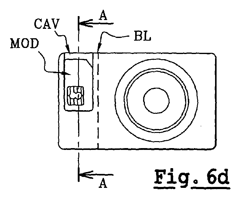
- a breaking line BL is pre-cut so as to both locally weaken the CD card CDC and separate the optical data storage area, optical part OP, from the rest of the CD card, rest part RP.
- a cavity CAV is created in the rest part RP.
- milling techniques can, for example, be used.
- an already manufactured GSM plug MOD is inserted in the cavity.
- the GSM plug MOD comprises a plastic body and integrated circuit electrically connected to contact pads flush with the surface of the plastic body.
- the plastic body is, for example, modified ABS, moulded ABS or PVC.
- the GSM plug MOD is fixed in the cavity CAV using a low tack adhesive LT.
- the GSM plug MOD can be easily removed from the cavity CAV.
- the GSM plug can be manufactured with conventional material independently and simultaneously. So the manufacturing is faster.
- the quality is lower because polycarbonate is not easy to manufacture.
- a specific glue has to be developed.
- the invention allows an enhanced quality and a cost reduction.
- PERS graphical elements PE are put on the CD card.
- the second data carrier can be, for example, an optical data carrier and more generally any other data carrier that is readable via a reading machine that is different than that of the first data carrier, for example, a magnetic data carrier.
- the cutting step CUT, the pre-cutting step PRECUT, and the creating step CREAT could also be replaced by the moulding step MOULD using an appropriate mould.
- the GSM plug MOD has been inserted in the cavity CAV using a low tack adhesive LT.
- Other techniques can also be used to fix the GSM plug MOD in the cavity CAV.
- the GSM plug MOD can be fixed by driving in techniques, for example, as illustrated in fig. 3, clipping techniques.
- the clipping elements CE can be moulded in the moulding step MOULD.
- soldering techniques can also be used. It can be, for example, hot soldering or ultrasound soldering.
- geometrical wedging techniques can be also used. To this purpose grooves or bevelled edges can be, for example, used.
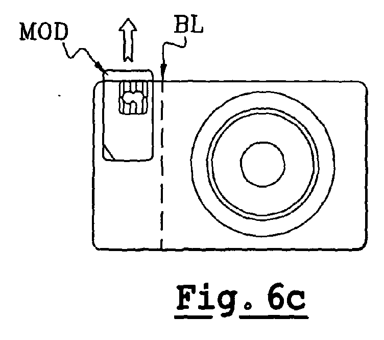
- the GSM plug MOD can also be fixed using sliding techniques. As illustrated in fig. 6 a through d, the plug can be inserted in the CD card in a visible manner. As illustrated in Fig. 6e, the plug can also be inserted in the CD card CDC in a non-visible manner. Alternatively, as illustrated in fig. 6d and 7, one of the edges of the GSM plug MOD can touch the breaking line BL, so that the rest part RP has to be break to remove the plug MOD from the cavity CAV. This technique can be used, for example, as a fraud detector.
- a hole H can be provided in the cavity CAV so that the GSM plug can be easily removed from the CD card CDC, for example, by finger pressure.
- a hole H for facilitating the removing of the GSM plug a notch, pre-cut lines or a groove can also be used.
- a relatively small portion of the card can be used for optical storage.
- Fig. 10b to 10e and in Fig. 11 b to g there are other possibilities to position the GSM plug in such a manner that the useful optical storage area is bigger.
- the GSM plus is transferred from the ISO position to the left.
- the GSM plus is translated from the ISO position to the left and rotated 180 degrees.
- the GSM plug is rotated 270 degrees from the ISO position.
- the GSM plug is rotated 90 degrees from the ISO position.
- Other positions are shown in Fig. 11b to 11g.
Abstract
A system comprises a first data carrier (MOD) and a
second data carrier (CDC). The first data carrier (MOD)
is inserted in the second data carrier (CDC). The system
is characterized in that, the first data carrier (MOD)
is removable from the second data carrier (CDC), in that
the first data carrier (MOD) is readable by a first
reading machine, and in that the second data carrier
(CDC) is readable by a second reading machine, which is
different than the first reading machine.


Description
- The invention concerns a system comprising a first data carrier and a second data carrier. The first data carrier is inserted in the second data carrier. The first data carrier may be, for example, a GSM plug. The second data carrier may be, for example, an optical data carrier.
- A prior art method of manufacturing a data carrier in the ISO format made of polycarbonate comprises the following steps.
In a moulding step a CD made of polycarbonate is moulded. The CD is 1.2 mm thick to meet the CD standards requirements. In a depositing step a round shaped metallic layer is deposited on the CD to define an optical data storage area. In a cutting step, the CD is cut so as to define a CD Card in the ISO format. In a first pre-cutting step, a breaking line is pre-cut so as to both locally weaken the CD card and separate the optical data storage area, optical part, from the rest of the CD card, rest part. In a second pre-cutting step, the outline of a GSM plug is precut in the rest part. In a thinning step, the rest part is thinned from 1.2 mm to 0.8 mm, to meet the GSM requirements. In a milling step, a cavity is milled inside the precut outline of the GSM plug. In an embedding step, an integrated circuit is embedded in the cavity using a glue developed specially for this purpose. In a personalization step, the integrated circuit is electrically connected to contact pads flush with the surface of the GSM plug and graphical elements are put in the CD card. - It is an object of the invention to allow a reduction of the cost.
- According to an aspect of the invention, a system comprising a first data carrier and a second data carrier, the first data carrier being inserted in the second data carrier, the system being characterized in that, the first data carrier is removable from the second data carrier, in that the first data carrier is readable by a first reading machine, and in that the second data carrier is readable by a second reading machine, which is different than the first reading machine.
- The first data carrier can be, for example, a GSM plug. The second data carrier can be, for example an optical data carrier. The manufacturing of the optical data carrier and the manufacturing of the GSM plug can be done independently and simultaneously. Consequently, the invention allows a cost reduction.
- These and other aspects of the invention will be described in greater detail hereinafter with reference to drawings.
-
- Figure 1 illustrates the different steps of the manufacturing method according to the invention;
- Figure 2 illustrates the inserting step, in which a low tack adhesive is used to fix the GSM plug;
- Figure 3 illustrates the use of a clipping technique to fix the GSM plug in the cavity in a removable manner;
- Figure 4 illustrates the use of a soldering technique to fix the GSM plug in the cavity in a removable manner;
- Figure 5 illustrates the use of a geometrical wedging technique to fix the GSM plug in the cavity in a removable manner;
- Figure 6 illustrates the use of a sliding technique to fix the GSM plug in the cavity in a removable manner;
- Figure 7 illustrates the use of a sliding technique to fix the GSM plug in the cavity in a removable manner;
- Figure 8 illustrates the use of a hole to facilitate the removing of the plug, for example, by finger pressure;
- Figure 9 illustrates a combination of different fixing techniques;
- Figure 10 and 11 illustrates various position of the GSM plug.
- FIG. 1 illustrates the different steps of the method according to the invention.
- In a moulding step MOULD, a CD is moulded. The mould can be, for example, a master CD made of glass, in which polycarbonate is injected.
- In a depositing step DEP, a round-shaped metallic layer M is deposited on the moulded CD to define an optical data storage area. Advantageously, a varnish protective layer can be deposited on the round-shaped metallic layer. The round-shaped metallic layer is preferably centred on the CD.
- In a cutting step CUT, the moulded CD is cut in the form of an ISO card CDC.
- In an optional pre-cutting step PRECUT which is followed by the cutting step CUT, a breaking line BL is pre-cut so as to both locally weaken the CD card CDC and separate the optical data storage area, optical part OP, from the rest of the CD card, rest part RP.
- In a creating step CREAT, a cavity CAV is created in the rest part RP. To that end, milling techniques can, for example, be used.
- In an inserting step INSERT, an already manufactured GSM plug MOD is inserted in the cavity. The GSM plug MOD comprises a plastic body and integrated circuit electrically connected to contact pads flush with the surface of the plastic body. The plastic body is, for example, modified ABS, moulded ABS or PVC. As illustrated in fig. 2, the GSM plug MOD is fixed in the cavity CAV using a low tack adhesive LT. Thus, the GSM plug MOD can be easily removed from the cavity CAV. Contrary to the prior art, the GSM plug can be manufactured with conventional material independently and simultaneously. So the manufacturing is faster. Further when creating a GSM plug MOD in a CD card of polycarbonate, the quality is lower because polycarbonate is not easy to manufacture. In addition we have to stick the module in the polycarbonate. To that end, a specific glue has to be developed. Thus, the invention allows an enhanced quality and a cost reduction.
- In a personalization step PERS graphical elements PE are put on the CD card.
- The description hereinbefore illustrates the following features:
- A system comprises a first data carrier (MOD) and a second data carrier (CDC). The first data carrier (MOD) is inserted in the second data carrier (CDC). The system is characterized in that, the first data carrier (MOD) is removable from the second data carrier (CDC), in that the first data carrier (MOD) is readable by a first reading machine, and in that the second data carrier (CDC) is readable by a second reading machine, which is different than the first reading machine.
-
- The description of the above mentioned embodiment illustrates rather than limits the invention. It will be evident that there are numerous alternatives, which fall within the scope of the appended claims. In this respect, the following closing remarks are made.
- The second data carrier can be, for example, an optical data carrier and more generally any other data carrier that is readable via a reading machine that is different than that of the first data carrier, for example, a magnetic data carrier.
- The cutting step CUT, the pre-cutting step PRECUT, and the creating step CREAT could also be replaced by the moulding step MOULD using an appropriate mould.
- In the inserting step INSERT, the GSM plug MOD has been inserted in the cavity CAV using a low tack adhesive LT. Other techniques can also be used to fix the GSM plug MOD in the cavity CAV.
As illustrated in fig. 3 to fig. 5 the GSM plug MOD can be fixed by driving in techniques, for example, as illustrated in fig. 3, clipping techniques. The clipping elements CE can be moulded in the moulding step MOULD.
As illustrated in fig. 4, soldering techniques can also be used. It can be, for example, hot soldering or ultrasound soldering.
As showed by fig.5, geometrical wedging techniques can be also used. To this purpose grooves or bevelled edges can be, for example, used.
As illustrated in fig. 6, the GSM plug MOD can also be fixed using sliding techniques.
As illustrated in fig. 6 a through d, the plug can be inserted in the CD card in a visible manner. As illustrated in Fig. 6e, the plug can also be inserted in the CD card CDC in a non-visible manner.
Alternatively, as illustrated in fig. 6d and 7, one of the edges of the GSM plug MOD can touch the breaking line BL, so that the rest part RP has to be break to remove the plug MOD from the cavity CAV. This technique can be used, for example, as a fraud detector. - As illustrated in Fig. 8 a hole H can be provided in the cavity CAV so that the GSM plug can be easily removed from the CD card CDC, for example, by finger pressure. Instead of using a hole H for facilitating the removing of the GSM plug, a notch, pre-cut lines or a groove can also be used.
- As illustrated in Fig. 9, combining the above-mentioned techniques (i.e. clipping, soldering geometrical wedging, sliding in techniques...) can also be used to both fix and enable the easy removing of the GSM plug MOD.
- As illustrated in Fig. 10a and fig. 11a if the GSM plug is in the ISO position, a relatively small portion of the card can be used for optical storage.
As illustrated in Fig. 10b to 10e and in Fig. 11 b to g, there are other possibilities to position the GSM plug in such a manner that the useful optical storage area is bigger. As illustrated in Fig. 10b the GSM plus is transferred from the ISO position to the left. As illustrated in Fig. 10 c, the GSM plus is translated from the ISO position to the left and rotated 180 degrees. As illustrated in Fig. 10d, the GSM plug is rotated 270 degrees from the ISO position. As illustrated in Fig. 10e the GSM plug is rotated 90 degrees from the ISO position. Other positions are shown in Fig. 11b to 11g.
Claims (5)
- A system comprising a first data carrier (MOD) and a second data carrier (CDC), the first data carrier (MOD) being inserted in the second data carrier (CDC), the system being characterized in that, the first data carrier (MOD) is removable from the second data carrier (CDC), in that the first data carrier (MOD) is readable by a first reading machine, and in that the second data carrier (CDC) is readable by a second reading machine, which is different than the first reading machine.
- The system according to claim 1, characterized in that the first data carrier (MOD) is a GSM plug (MOD) and in that the second data carrier is an optical data carrier (CDC).
- The system according to claim 1, characterized in that the first data carrier (MOD) is inserted in the second data carrier (CDC) using clipping elements.
- The system according to claim 1, characterized in that the first data carrier (CDC) is inserted in the second data carrier using sliding techniques.
- The system according to claim 2, characterized in that one edge of the GSM plug MOD touch a breaking line of the optical data carrier (CDC).
Priority Applications (5)
| Application Number | Priority Date | Filing Date | Title |
|---|---|---|---|
| EP02291732A EP1380990A1 (en) | 2002-07-09 | 2002-07-09 | Data carrier being removably mounted on other data carrier of different type |
| PCT/IB2003/003146 WO2004006179A1 (en) | 2002-07-09 | 2003-07-07 | Removably connected data carriers made of different materials and readable by respective different reader types |
| AU2003281394A AU2003281394A1 (en) | 2002-07-09 | 2003-07-07 | Removably connected data carriers made of different materials and readable by respective different reader types |
| US10/520,775 US20050250392A1 (en) | 2002-07-09 | 2003-07-07 | Removably connected data carriers made of different materials and readable by respective different reader types |
| EP03741004A EP1522044A1 (en) | 2002-07-09 | 2003-07-07 | Removably connected data carriers made of different materials and readable by respective different reader types |
Applications Claiming Priority (1)
| Application Number | Priority Date | Filing Date | Title |
|---|---|---|---|
| EP02291732A EP1380990A1 (en) | 2002-07-09 | 2002-07-09 | Data carrier being removably mounted on other data carrier of different type |
Publications (1)
| Publication Number | Publication Date |
|---|---|
| EP1380990A1 true EP1380990A1 (en) | 2004-01-14 |
Family
ID=29724577
Family Applications (2)
| Application Number | Title | Priority Date | Filing Date |
|---|---|---|---|
| EP02291732A Withdrawn EP1380990A1 (en) | 2002-07-09 | 2002-07-09 | Data carrier being removably mounted on other data carrier of different type |
| EP03741004A Withdrawn EP1522044A1 (en) | 2002-07-09 | 2003-07-07 | Removably connected data carriers made of different materials and readable by respective different reader types |
Family Applications After (1)
| Application Number | Title | Priority Date | Filing Date |
|---|---|---|---|
| EP03741004A Withdrawn EP1522044A1 (en) | 2002-07-09 | 2003-07-07 | Removably connected data carriers made of different materials and readable by respective different reader types |
Country Status (4)
| Country | Link |
|---|---|
| US (1) | US20050250392A1 (en) |
| EP (2) | EP1380990A1 (en) |
| AU (1) | AU2003281394A1 (en) |
| WO (1) | WO2004006179A1 (en) |
Cited By (1)
| Publication number | Priority date | Publication date | Assignee | Title |
|---|---|---|---|---|
| WO2006136942A1 (en) * | 2005-06-24 | 2006-12-28 | Axalto Sa | Portable device comprising two cavities for two data carriers |
Families Citing this family (4)
| Publication number | Priority date | Publication date | Assignee | Title |
|---|---|---|---|---|
| WO2006054886A1 (en) | 2004-11-18 | 2006-05-26 | N.V. Nutricia | Thickener composition for dysphagia patients |
| EP1903480A1 (en) * | 2006-09-22 | 2008-03-26 | Axalto SA | Portable device comprising two separable data supports utilisable by two different readers, and manufacturing process |
| EP2117003A3 (en) | 2006-11-20 | 2010-01-13 | EcoDisc Technology AG | Smart video card |
| PL2418969T3 (en) | 2009-04-15 | 2013-08-30 | Nutricia Nv | Anti-reflux infant nutrition |
Citations (5)
| Publication number | Priority date | Publication date | Assignee | Title |
|---|---|---|---|---|
| EP0328124A2 (en) * | 1988-02-12 | 1989-08-16 | Deutsche Telekom AG | Credit card with implanted IC |
| JPH0355296A (en) * | 1989-07-25 | 1991-03-11 | Toshiba Corp | Ic card, ic module for ic card and card main body |
| US5049728A (en) * | 1990-04-04 | 1991-09-17 | Rovin George H | IC card system with removable IC modules |
| DE19943092A1 (en) * | 1999-09-09 | 2001-03-15 | Orga Kartensysteme Gmbh | Data carrier with semiconductor circuit and detachable optical storage medium |
| WO2001024169A1 (en) * | 1999-09-30 | 2001-04-05 | Bryan Ekus | Apparatus and method for reading/writing data from/to a storage device having multiple storage areas |
Family Cites Families (10)
| Publication number | Priority date | Publication date | Assignee | Title |
|---|---|---|---|---|
| FI105630B (en) * | 1993-05-31 | 2000-09-15 | Nokia Mobile Phones Ltd | SIM card adapter |
| ES2102317B1 (en) * | 1994-09-19 | 1998-04-16 | Nacional Moneda Timbre | INTELLIGENT CARD FOR USE IN TELEPHONY AND SIMILAR. |
| FR2773900B1 (en) * | 1998-01-22 | 2000-02-18 | Gemplus Card Int | CARD WITH INTEGRATED CONTACT CIRCUIT (S), COMPRISING A DETACHABLE MINICARD |
| ATE255765T1 (en) * | 1999-07-10 | 2003-12-15 | Karl-Heinz Schoppe | DISK-SHAPED OPTICAL DISK CARRIER |
| US20030173409A1 (en) * | 2000-06-28 | 2003-09-18 | Werner Vogt | Transport or conveyor unit for a chip, particularly a telephone chip |
| DE10050960A1 (en) * | 2000-06-28 | 2002-01-17 | Tronic Mgm Ag Urdorf A | Combined package containing telephone chip attached to CD card for transport to be detached from CD to insert into mobile phone |
| US7080783B2 (en) * | 2000-09-05 | 2006-07-25 | Digital Castles Llc | Data storage card having both linear and annular data regions |
| PL365289A1 (en) * | 2001-02-22 | 2004-12-27 | Tele-Cd Company A/S | Method for production of an optical disc with a detachable module |
| US6832730B2 (en) * | 2001-07-27 | 2004-12-21 | Storcard, Inc. | Smart card with rotating storage |
| US6758404B2 (en) * | 2001-08-03 | 2004-07-06 | General Instrument Corporation | Media cipher smart card |
-
2002
- 2002-07-09 EP EP02291732A patent/EP1380990A1/en not_active Withdrawn
-
2003
- 2003-07-07 AU AU2003281394A patent/AU2003281394A1/en not_active Abandoned
- 2003-07-07 EP EP03741004A patent/EP1522044A1/en not_active Withdrawn
- 2003-07-07 WO PCT/IB2003/003146 patent/WO2004006179A1/en not_active Application Discontinuation
- 2003-07-07 US US10/520,775 patent/US20050250392A1/en not_active Abandoned
Patent Citations (5)
| Publication number | Priority date | Publication date | Assignee | Title |
|---|---|---|---|---|
| EP0328124A2 (en) * | 1988-02-12 | 1989-08-16 | Deutsche Telekom AG | Credit card with implanted IC |
| JPH0355296A (en) * | 1989-07-25 | 1991-03-11 | Toshiba Corp | Ic card, ic module for ic card and card main body |
| US5049728A (en) * | 1990-04-04 | 1991-09-17 | Rovin George H | IC card system with removable IC modules |
| DE19943092A1 (en) * | 1999-09-09 | 2001-03-15 | Orga Kartensysteme Gmbh | Data carrier with semiconductor circuit and detachable optical storage medium |
| WO2001024169A1 (en) * | 1999-09-30 | 2001-04-05 | Bryan Ekus | Apparatus and method for reading/writing data from/to a storage device having multiple storage areas |
Non-Patent Citations (1)
| Title |
|---|
| PATENT ABSTRACTS OF JAPAN vol. 015, no. 203 (M - 1116) 24 May 1991 (1991-05-24) * |
Cited By (1)
| Publication number | Priority date | Publication date | Assignee | Title |
|---|---|---|---|---|
| WO2006136942A1 (en) * | 2005-06-24 | 2006-12-28 | Axalto Sa | Portable device comprising two cavities for two data carriers |
Also Published As
| Publication number | Publication date |
|---|---|
| AU2003281394A1 (en) | 2004-01-23 |
| WO2004006179A1 (en) | 2004-01-15 |
| EP1522044A1 (en) | 2005-04-13 |
| US20050250392A1 (en) | 2005-11-10 |
Similar Documents
| Publication | Publication Date | Title |
|---|---|---|
| US9195930B2 (en) | Method for manufacturing a card based on a substrate | |
| CN101248446B (en) | Adhesive format adapter for a storage device and method for the production thereof | |
| US7183636B1 (en) | Adapter for a chip card having a reduced format in comparison with the standard SIM mini-card format | |
| EP1810227B1 (en) | Personalized usb-key type electronic device and method for making same | |
| CN105142872A (en) | Method of making a device housing and device housing comprising a transparent lens with a stepped flange | |
| FR2872946A1 (en) | METHOD FOR MANUFACTURING A MINI UICC CHIP CARD HOLDER WITH UICC PLUG-IN ADAPTER AND A SUPPORT OBTAINED | |
| FR2949011A1 (en) | CARD FOR FORMING A COMPUTER ORGAN, AND METHODS OF MANUFACTURING THE SAME AND COMPUTER ORGAN | |
| EP1380990A1 (en) | Data carrier being removably mounted on other data carrier of different type | |
| EP1190378B1 (en) | Portable integrated circuit device and method for the production thereof | |
| FR2794266A1 (en) | METHOD FOR MANUFACTURING PORTABLE ELECTRONIC DEVICE WITH INTEGRATED CIRCUIT HAVING LOW COST DIELECTRIC | |
| EP1073998B1 (en) | Method for making a contact integrated circuit card and resulting card | |
| EP3072087B1 (en) | Microcircuit card containing multiple pre-cutout cards having one and the same span of contacts | |
| FR2960819A1 (en) | Support manufacturing method for contactless payment embarked by mobile telephone, involves stamping free contour part of detachable card remaining attached to support to create recess zone separating contour part of card from support | |
| CN103514478B (en) | Data medium with microcircuit card and the method for manufacturing the card | |
| EP1546989B1 (en) | Chip card reader with a transparent housing | |
| CN102385715B (en) | Method based on substrate manufacture card | |
| WO2006136942A1 (en) | Portable device comprising two cavities for two data carriers | |
| CN100371948C (en) | Method of manufacturing a data carrier | |
| JP4459670B2 (en) | UIM with plate frame | |
| FR3131035A1 (en) | SIM card holder and SIM card ejector | |
| EP1903480A1 (en) | Portable device comprising two separable data supports utilisable by two different readers, and manufacturing process | |
| US8695886B1 (en) | Memory chip device | |
| EP4012612A1 (en) | Method for manufacturing a smart card with positioning of metal insert | |
| FR2985985A1 (en) | INVIOLABLE SEAL FOR PACKAGING, PROCESS FOR MANUFACTURING AND USE OF AN INVIOLABLE SEAL | |
| EP2521073A1 (en) | Method for preparing a cellulose card mounting for a minicard |
Legal Events
| Date | Code | Title | Description |
|---|---|---|---|
| PUAI | Public reference made under article 153(3) epc to a published international application that has entered the european phase |
Free format text: ORIGINAL CODE: 0009012 |
|
| AK | Designated contracting states |
Kind code of ref document: A1 Designated state(s): AT BE BG CH CY CZ DE DK EE ES FI FR GB GR IE IT LI LU MC NL PT SE SK TR |
|
| AX | Request for extension of the european patent |
Extension state: AL LT LV MK RO SI |
|
| RAP1 | Party data changed (applicant data changed or rights of an application transferred) |
Owner name: AXALTO S.A. |
|
| AKX | Designation fees paid | ||
| REG | Reference to a national code |
Ref country code: DE Ref legal event code: 8566 |
|
| STAA | Information on the status of an ep patent application or granted ep patent |
Free format text: STATUS: THE APPLICATION IS DEEMED TO BE WITHDRAWN |
|
| 18D | Application deemed to be withdrawn |
Effective date: 20040715 |