EP1380809A2 - Ceramic composite bodies - Google Patents
Ceramic composite bodies Download PDFInfo
- Publication number
- EP1380809A2 EP1380809A2 EP20030015441 EP03015441A EP1380809A2 EP 1380809 A2 EP1380809 A2 EP 1380809A2 EP 20030015441 EP20030015441 EP 20030015441 EP 03015441 A EP03015441 A EP 03015441A EP 1380809 A2 EP1380809 A2 EP 1380809A2
- Authority
- EP
- European Patent Office
- Prior art keywords
- layer
- material layer
- silicon
- metal
- ceramic composite
- Prior art date
- Legal status (The legal status is an assumption and is not a legal conclusion. Google has not performed a legal analysis and makes no representation as to the accuracy of the status listed.)
- Granted
Links
- 239000000919 ceramic Substances 0.000 title claims abstract description 64
- 239000002131 composite material Substances 0.000 title claims abstract description 32
- 229910052751 metal Inorganic materials 0.000 claims abstract description 53
- 239000002184 metal Substances 0.000 claims abstract description 52
- HBMJWWWQQXIZIP-UHFFFAOYSA-N silicon carbide Chemical compound [Si+]#[C-] HBMJWWWQQXIZIP-UHFFFAOYSA-N 0.000 claims abstract description 29
- OKTJSMMVPCPJKN-UHFFFAOYSA-N Carbon Chemical compound [C] OKTJSMMVPCPJKN-UHFFFAOYSA-N 0.000 claims abstract description 28
- 229910010271 silicon carbide Inorganic materials 0.000 claims abstract description 27
- 229910052799 carbon Inorganic materials 0.000 claims abstract description 24
- 239000002245 particle Substances 0.000 claims abstract description 23
- 239000011148 porous material Substances 0.000 claims abstract description 15
- 238000004519 manufacturing process Methods 0.000 claims abstract description 10
- 239000011230 binding agent Substances 0.000 claims abstract description 8
- 239000000463 material Substances 0.000 claims description 103
- 229910052710 silicon Inorganic materials 0.000 claims description 31
- XUIMIQQOPSSXEZ-UHFFFAOYSA-N Silicon Chemical compound [Si] XUIMIQQOPSSXEZ-UHFFFAOYSA-N 0.000 claims description 29
- 238000001764 infiltration Methods 0.000 claims description 28
- 230000008595 infiltration Effects 0.000 claims description 28
- 239000010703 silicon Substances 0.000 claims description 28
- 150000004767 nitrides Chemical class 0.000 claims description 20
- 238000000034 method Methods 0.000 claims description 17
- 239000000843 powder Substances 0.000 claims description 11
- 230000001681 protective effect Effects 0.000 claims description 8
- 229910052719 titanium Inorganic materials 0.000 claims description 5
- 239000010936 titanium Substances 0.000 claims description 5
- 229920000049 Carbon (fiber) Polymers 0.000 claims description 4
- 229910000676 Si alloy Inorganic materials 0.000 claims description 4
- 239000000853 adhesive Substances 0.000 claims description 4
- 230000001070 adhesive effect Effects 0.000 claims description 4
- 229910052782 aluminium Inorganic materials 0.000 claims description 4
- 229910052796 boron Inorganic materials 0.000 claims description 4
- 239000004917 carbon fiber Substances 0.000 claims description 4
- 239000004033 plastic Substances 0.000 claims description 4
- 229920003023 plastic Polymers 0.000 claims description 4
- 229910052726 zirconium Inorganic materials 0.000 claims description 4
- 239000000806 elastomer Substances 0.000 claims description 3
- 229920001971 elastomer Polymers 0.000 claims description 3
- 150000001247 metal acetylides Chemical class 0.000 claims description 3
- 150000002739 metals Chemical class 0.000 claims description 3
- 229910021382 natural graphite Inorganic materials 0.000 claims description 3
- 229920003002 synthetic resin Polymers 0.000 claims description 3
- XAGFODPZIPBFFR-UHFFFAOYSA-N aluminium Chemical compound [Al] XAGFODPZIPBFFR-UHFFFAOYSA-N 0.000 claims description 2
- 229910021383 artificial graphite Inorganic materials 0.000 claims description 2
- 239000000571 coke Substances 0.000 claims description 2
- 229910021397 glassy carbon Inorganic materials 0.000 claims description 2
- -1 metal nitride Chemical class 0.000 claims description 2
- 239000011368 organic material Substances 0.000 claims description 2
- 230000001590 oxidative effect Effects 0.000 claims description 2
- 239000000057 synthetic resin Substances 0.000 claims 2
- 229910052582 BN Inorganic materials 0.000 claims 1
- 208000031872 Body Remains Diseases 0.000 claims 1
- ZOXJGFHDIHLPTG-UHFFFAOYSA-N Boron Chemical compound [B] ZOXJGFHDIHLPTG-UHFFFAOYSA-N 0.000 claims 1
- PZNSFCLAULLKQX-UHFFFAOYSA-N Boron nitride Chemical compound N#B PZNSFCLAULLKQX-UHFFFAOYSA-N 0.000 claims 1
- 229910052581 Si3N4 Inorganic materials 0.000 claims 1
- RTAQQCXQSZGOHL-UHFFFAOYSA-N Titanium Chemical compound [Ti] RTAQQCXQSZGOHL-UHFFFAOYSA-N 0.000 claims 1
- NRTOMJZYCJJWKI-UHFFFAOYSA-N Titanium nitride Chemical compound [Ti]#N NRTOMJZYCJJWKI-UHFFFAOYSA-N 0.000 claims 1
- QCWXUUIWCKQGHC-UHFFFAOYSA-N Zirconium Chemical compound [Zr] QCWXUUIWCKQGHC-UHFFFAOYSA-N 0.000 claims 1
- PMHQVHHXPFUNSP-UHFFFAOYSA-M copper(1+);methylsulfanylmethane;bromide Chemical compound Br[Cu].CSC PMHQVHHXPFUNSP-UHFFFAOYSA-M 0.000 claims 1
- 239000002657 fibrous material Substances 0.000 claims 1
- 238000010438 heat treatment Methods 0.000 claims 1
- HQVNEWCFYHHQES-UHFFFAOYSA-N silicon nitride Chemical compound N12[Si]34N5[Si]62N3[Si]51N64 HQVNEWCFYHHQES-UHFFFAOYSA-N 0.000 claims 1
- 239000004753 textile Substances 0.000 claims 1
- ZVWKZXLXHLZXLS-UHFFFAOYSA-N zirconium nitride Chemical compound [Zr]#N ZVWKZXLXHLZXLS-UHFFFAOYSA-N 0.000 claims 1
- 238000005245 sintering Methods 0.000 abstract description 6
- 239000000203 mixture Substances 0.000 description 10
- 230000000694 effects Effects 0.000 description 8
- 239000011159 matrix material Substances 0.000 description 7
- 238000006243 chemical reaction Methods 0.000 description 6
- 239000006096 absorbing agent Substances 0.000 description 5
- 239000007779 soft material Substances 0.000 description 5
- 239000007787 solid Substances 0.000 description 5
- 239000004744 fabric Substances 0.000 description 4
- 239000000835 fiber Substances 0.000 description 4
- 239000007788 liquid Substances 0.000 description 4
- 229910001338 liquidmetal Inorganic materials 0.000 description 4
- 239000003575 carbonaceous material Substances 0.000 description 3
- 229910010293 ceramic material Inorganic materials 0.000 description 3
- 206010041662 Splinter Diseases 0.000 description 2
- 239000000654 additive Substances 0.000 description 2
- 229910045601 alloy Inorganic materials 0.000 description 2
- 239000000956 alloy Substances 0.000 description 2
- 229920006231 aramid fiber Polymers 0.000 description 2
- 239000007795 chemical reaction product Substances 0.000 description 2
- 229910052804 chromium Inorganic materials 0.000 description 2
- 230000006378 damage Effects 0.000 description 2
- 239000000945 filler Substances 0.000 description 2
- 239000012634 fragment Substances 0.000 description 2
- 238000009434 installation Methods 0.000 description 2
- 229910052742 iron Inorganic materials 0.000 description 2
- 238000000626 liquid-phase infiltration Methods 0.000 description 2
- 238000002844 melting Methods 0.000 description 2
- 230000008018 melting Effects 0.000 description 2
- 239000011185 multilayer composite material Substances 0.000 description 2
- 239000000047 product Substances 0.000 description 2
- 239000011226 reinforced ceramic Substances 0.000 description 2
- 230000006641 stabilisation Effects 0.000 description 2
- 238000011105 stabilization Methods 0.000 description 2
- 239000000126 substance Substances 0.000 description 2
- 229920001169 thermoplastic Polymers 0.000 description 2
- 229910000831 Steel Inorganic materials 0.000 description 1
- UGACIEPFGXRWCH-UHFFFAOYSA-N [Si].[Ti] Chemical compound [Si].[Ti] UGACIEPFGXRWCH-UHFFFAOYSA-N 0.000 description 1
- 238000010521 absorption reaction Methods 0.000 description 1
- 238000004026 adhesive bonding Methods 0.000 description 1
- 239000004760 aramid Substances 0.000 description 1
- 230000015572 biosynthetic process Effects 0.000 description 1
- 229910021386 carbon form Inorganic materials 0.000 description 1
- 239000007833 carbon precursor Substances 0.000 description 1
- 239000004568 cement Substances 0.000 description 1
- 239000003245 coal Substances 0.000 description 1
- 230000001427 coherent effect Effects 0.000 description 1
- 238000004939 coking Methods 0.000 description 1
- 150000001875 compounds Chemical class 0.000 description 1
- 238000000354 decomposition reaction Methods 0.000 description 1
- 239000003822 epoxy resin Substances 0.000 description 1
- 239000002360 explosive Substances 0.000 description 1
- 230000002349 favourable effect Effects 0.000 description 1
- 239000003733 fiber-reinforced composite Substances 0.000 description 1
- 238000013467 fragmentation Methods 0.000 description 1
- 238000006062 fragmentation reaction Methods 0.000 description 1
- 229910002804 graphite Inorganic materials 0.000 description 1
- 239000010439 graphite Substances 0.000 description 1
- LNEPOXFFQSENCJ-UHFFFAOYSA-N haloperidol Chemical compound C1CC(O)(C=2C=CC(Cl)=CC=2)CCN1CCCC(=O)C1=CC=C(F)C=C1 LNEPOXFFQSENCJ-UHFFFAOYSA-N 0.000 description 1
- 229920001903 high density polyethylene Polymers 0.000 description 1
- 239000004700 high-density polyethylene Substances 0.000 description 1
- 239000004615 ingredient Substances 0.000 description 1
- 238000001746 injection moulding Methods 0.000 description 1
- 229920000592 inorganic polymer Polymers 0.000 description 1
- 239000000155 melt Substances 0.000 description 1
- 238000001000 micrograph Methods 0.000 description 1
- 229910052750 molybdenum Inorganic materials 0.000 description 1
- 229920000620 organic polymer Polymers 0.000 description 1
- 229920000647 polyepoxide Polymers 0.000 description 1
- 229920000642 polymer Polymers 0.000 description 1
- 239000002952 polymeric resin Substances 0.000 description 1
- 229920000098 polyolefin Polymers 0.000 description 1
- 238000003825 pressing Methods 0.000 description 1
- 238000000197 pyrolysis Methods 0.000 description 1
- 239000002994 raw material Substances 0.000 description 1
- 229920005989 resin Polymers 0.000 description 1
- 239000011347 resin Substances 0.000 description 1
- 239000004576 sand Substances 0.000 description 1
- 239000010959 steel Substances 0.000 description 1
- 230000007704 transition Effects 0.000 description 1
- MTPVUVINMAGMJL-UHFFFAOYSA-N trimethyl(1,1,2,2,2-pentafluoroethyl)silane Chemical compound C[Si](C)(C)C(F)(F)C(F)(F)F MTPVUVINMAGMJL-UHFFFAOYSA-N 0.000 description 1
- XLYOFNOQVPJJNP-UHFFFAOYSA-N water Substances O XLYOFNOQVPJJNP-UHFFFAOYSA-N 0.000 description 1
- 238000009736 wetting Methods 0.000 description 1
Images
Classifications
-
- F—MECHANICAL ENGINEERING; LIGHTING; HEATING; WEAPONS; BLASTING
- F41—WEAPONS
- F41H—ARMOUR; ARMOURED TURRETS; ARMOURED OR ARMED VEHICLES; MEANS OF ATTACK OR DEFENCE, e.g. CAMOUFLAGE, IN GENERAL
- F41H5/00—Armour; Armour plates
- F41H5/02—Plate construction
- F41H5/04—Plate construction composed of more than one layer
- F41H5/0414—Layered armour containing ceramic material
-
- Y—GENERAL TAGGING OF NEW TECHNOLOGICAL DEVELOPMENTS; GENERAL TAGGING OF CROSS-SECTIONAL TECHNOLOGIES SPANNING OVER SEVERAL SECTIONS OF THE IPC; TECHNICAL SUBJECTS COVERED BY FORMER USPC CROSS-REFERENCE ART COLLECTIONS [XRACs] AND DIGESTS
- Y10—TECHNICAL SUBJECTS COVERED BY FORMER USPC
- Y10T—TECHNICAL SUBJECTS COVERED BY FORMER US CLASSIFICATION
- Y10T428/00—Stock material or miscellaneous articles
- Y10T428/24—Structurally defined web or sheet [e.g., overall dimension, etc.]
- Y10T428/24942—Structurally defined web or sheet [e.g., overall dimension, etc.] including components having same physical characteristic in differing degree
-
- Y—GENERAL TAGGING OF NEW TECHNOLOGICAL DEVELOPMENTS; GENERAL TAGGING OF CROSS-SECTIONAL TECHNOLOGIES SPANNING OVER SEVERAL SECTIONS OF THE IPC; TECHNICAL SUBJECTS COVERED BY FORMER USPC CROSS-REFERENCE ART COLLECTIONS [XRACs] AND DIGESTS
- Y10—TECHNICAL SUBJECTS COVERED BY FORMER USPC
- Y10T—TECHNICAL SUBJECTS COVERED BY FORMER US CLASSIFICATION
- Y10T428/00—Stock material or miscellaneous articles
- Y10T428/249921—Web or sheet containing structurally defined element or component
- Y10T428/249953—Composite having voids in a component [e.g., porous, cellular, etc.]
- Y10T428/249955—Void-containing component partially impregnated with adjacent component
- Y10T428/249956—Void-containing component is inorganic
- Y10T428/249957—Inorganic impregnant
-
- Y—GENERAL TAGGING OF NEW TECHNOLOGICAL DEVELOPMENTS; GENERAL TAGGING OF CROSS-SECTIONAL TECHNOLOGIES SPANNING OVER SEVERAL SECTIONS OF THE IPC; TECHNICAL SUBJECTS COVERED BY FORMER USPC CROSS-REFERENCE ART COLLECTIONS [XRACs] AND DIGESTS
- Y10—TECHNICAL SUBJECTS COVERED BY FORMER USPC
- Y10T—TECHNICAL SUBJECTS COVERED BY FORMER US CLASSIFICATION
- Y10T428/00—Stock material or miscellaneous articles
- Y10T428/249921—Web or sheet containing structurally defined element or component
- Y10T428/249953—Composite having voids in a component [e.g., porous, cellular, etc.]
- Y10T428/249967—Inorganic matrix in void-containing component
- Y10T428/249969—Of silicon-containing material [e.g., glass, etc.]
-
- Y—GENERAL TAGGING OF NEW TECHNOLOGICAL DEVELOPMENTS; GENERAL TAGGING OF CROSS-SECTIONAL TECHNOLOGIES SPANNING OVER SEVERAL SECTIONS OF THE IPC; TECHNICAL SUBJECTS COVERED BY FORMER USPC CROSS-REFERENCE ART COLLECTIONS [XRACs] AND DIGESTS
- Y10—TECHNICAL SUBJECTS COVERED BY FORMER USPC
- Y10T—TECHNICAL SUBJECTS COVERED BY FORMER US CLASSIFICATION
- Y10T428/00—Stock material or miscellaneous articles
- Y10T428/249921—Web or sheet containing structurally defined element or component
- Y10T428/249953—Composite having voids in a component [e.g., porous, cellular, etc.]
- Y10T428/249981—Plural void-containing components
-
- Y—GENERAL TAGGING OF NEW TECHNOLOGICAL DEVELOPMENTS; GENERAL TAGGING OF CROSS-SECTIONAL TECHNOLOGIES SPANNING OVER SEVERAL SECTIONS OF THE IPC; TECHNICAL SUBJECTS COVERED BY FORMER USPC CROSS-REFERENCE ART COLLECTIONS [XRACs] AND DIGESTS
- Y10—TECHNICAL SUBJECTS COVERED BY FORMER USPC
- Y10T—TECHNICAL SUBJECTS COVERED BY FORMER US CLASSIFICATION
- Y10T428/00—Stock material or miscellaneous articles
- Y10T428/249921—Web or sheet containing structurally defined element or component
- Y10T428/249953—Composite having voids in a component [e.g., porous, cellular, etc.]
- Y10T428/249987—With nonvoid component of specified composition
- Y10T428/24999—Inorganic
-
- Y—GENERAL TAGGING OF NEW TECHNOLOGICAL DEVELOPMENTS; GENERAL TAGGING OF CROSS-SECTIONAL TECHNOLOGIES SPANNING OVER SEVERAL SECTIONS OF THE IPC; TECHNICAL SUBJECTS COVERED BY FORMER USPC CROSS-REFERENCE ART COLLECTIONS [XRACs] AND DIGESTS
- Y10—TECHNICAL SUBJECTS COVERED BY FORMER USPC
- Y10T—TECHNICAL SUBJECTS COVERED BY FORMER US CLASSIFICATION
- Y10T442/00—Fabric [woven, knitted, or nonwoven textile or cloth, etc.]
- Y10T442/20—Coated or impregnated woven, knit, or nonwoven fabric which is not [a] associated with another preformed layer or fiber layer or, [b] with respect to woven and knit, characterized, respectively, by a particular or differential weave or knit, wherein the coating or impregnation is neither a foamed material nor a free metal or alloy layer
- Y10T442/2615—Coating or impregnation is resistant to penetration by solid implements
- Y10T442/2623—Ballistic resistant
Definitions
- the invention relates to ceramic composite bodies comprising at least two Layers, especially for protective armor, for civil and military Areas of application are suitable.
- the invention relates to a single body mainly multilayer composite material containing silicon carbide (SiC), with one essentially bonded in a matrix of free silicon (Si) SiC existing external material layer and an internal one Material layer containing loosely bound SiC ceramic powder, as well as a Process for their production and uses of these composite bodies.
- SiC silicon carbide
- Si free silicon
- the large distances to the target objects generally require long distances Hits distances. Therefore, there are fewer requirements for multi-hit suitability posed.
- Flat plates are often used as armor for military purposes Additional armor for land and water vehicles as well as for helicopters, containers, Containers, shelters and field fortifications used.
- Armor consisting of one or more armored steel plates is usually like this treats that at least the side facing the threat is extremely hard and so that the bullet breaks.
- the side facing away from the threat is more ductile or more visibly designed to withstand the energy of the projectile through a material deformation to absorb. This also results in that for armored plates from others Materials typical structure.
- ceramic materials Compared to metals, ceramic materials have the advantage of being higher Hardness and lower specific weight. Since the monolithic ceramic at Shelling shows a typical brittle fracture behavior, ceramic plates burst (monolithic ceramics) with formation of many coarse to very fine fragments. The Use of ceramic plates without additional backing (support material and Fragmentation) on the side facing away from the entry of the projectile is due the splinter exit does not make sense when fired at. Due to the shelling in generally completely destroyed the respective ceramic plate. A multiple bombardment (multi-hit) can then no longer be held.
- the front plate made of monolithic ceramics has the task of deforming the remaining floor and, if necessary, the Breaking hard core.
- a deformable one attached behind the ceramic plate Armoring, the backing has the task of projectile, bullet debris and Ceramic fragments to catch or absorb and the remaining ceramic plate to stabilize. It is also called the absorber layer below.
- the backing generally consists of highly stretchable and tear-resistant fabrics (Aramid fiber fabric, HDPE fabric, etc.), metal or plastics.
- a multilayer armor plate which consists of a conventional ceramic plate as a front plate and one behind it Absorber plate consists of so-called chemically bound ceramics.
- the Chemically bonded ceramics consist of hard fillers such as Fibers or ceramic powder, and a binding phase (or matrix) made of with organic or inorganic polymers modified cements, which harden at low temperatures. The hard fillers lead to one Blunting, deflection and destruction of the projectile.
- a composite body that comprises at least two layers, characterized in that one outside lying bullet-breaking ceramic layer (front panel) essentially a carbide and a carbide-forming metal, preferably SiC and Si (Material layer A) exists, and an internal one firmly connected to it Layer (material layer B), the weakly or loosely bound ceramic powder contains, which consists essentially of SiC.
- bullet-breaking ceramic layer front panel
- a carbide-forming metal preferably SiC and Si
- Layer material layer B
- a method for producing such a composite body specified in which the multi-layer composite material by the Liquid infiltration of a porous green body made of ceramic particles and Carbon material through a carbide-forming metal, in particular silicon metal, is made by liquid metal infiltration in one common process step from both the outer ceramic layer Carbide and carbide-forming metal, preferably SiC and Si (material layer A), as also the inner layer of weakly or loosely bound ceramic powder predominantly SiC (material layer B) is formed, as well as both layers firmly are chemically linked together.
- the multi-layer composite material by the Liquid infiltration of a porous green body made of ceramic particles and Carbon material through a carbide-forming metal, in particular silicon metal is made by liquid metal infiltration in one common process step from both the outer ceramic layer Carbide and carbide-forming metal, preferably SiC and Si (material layer A), as also the inner layer of weakly or loosely bound ceramic powder predominantly SiC (material layer B) is formed, as well as both layers firmly are chemically linked together.
- the invention is based on the knowledge that powdery or particulate Ceramic, similar to a sand fill, has a very favorable absorption behavior against ballistic effects, provided the powdery material is mechanical is stabilized or held together.
- This cohesion will according to the invention by the chemically firmly bonded ceramic layer (Material layer A), as well as by the during the metal melt infiltration sintering process of the ceramic mixture of the green body in the area of Material layer B reached.
- the composite body according to the invention therefore comprises at least two layers, an outer material layer A, which contains phases made of a carbide-forming metal and the carbide of this metal, preferably reaction-bonded silicon carbide (SiC) and silicon, also referred to as SiSiC, and a material layer B behind it, which through Sintering contains loosely bound SiC ceramic powder or particles, and optionally further layers arranged behind them, in particular made of material A or of fiber-containing backing. These additional layers further improve the energy-absorbing effect of the armor.
- Loosely bound ceramic powder or particles is to be understood in particular as material whose strength is at least 20% below that of the material of material layer A.
- liquid metal infiltration preferably with a Silicon melt - is in the material layer A by reaction of the carbide-forming Metal with carbon formed a ceramic, which in addition to very high hardness is a good one Exhibits fracture toughness or damage tolerance. This will make it for the Multiple bombardment harmful ceramic brittle fracture behavior in advantageous Suppressed way.
- An alloy is preferably used as the infiltration metal, which contains at least a mass fraction of 50% silicon, is particularly preferred is technical silicon or pure silicon.
- Fe, Cr, or Ni forms from the im Carbon precursors of material layer A preferably contain silicon carbide.
- the carbon forms preferably titanium carbide in addition to silicon carbide.
- the particles of silicon carbide and nitrides contained in material layer B. are at the temperature of infiltration with the liquid metal to the Contact points sintered together, creating a loose structure with pores.
- the non-volatile pyrolysis products of the organic binder of the raw material mixture also contribute to the strength of the material layer B.
- the material layer A preferably contains a mass fraction of at least 70% of SiC particles which are embedded in a matrix of free silicon.
- the mass fraction of SiC is preferably above 75% and particularly preferably above 85%.
- the mass fraction of free silicon which should also include all silicon mixed phases with other metallic elements, is above 2.8%.
- the mass fraction of free silicon is preferably in the range from 3 to 21% and particularly preferably in the range from 3 to 15%.
- the material layer A is built up in such a way that the highest possible hardness is achieved, which can be achieved, for example, by the highest possible density, ideally the theoretical density.
- the porosity (volume fraction of the pores in the total volume) of the material layer A is therefore preferably less than 20% or the density is at least 2.1 g / cm 3, and the porosity is particularly preferably less than 10% or the density above 2.2 g / cm 3 .
- material A still has free carbon and, if appropriate, ceramic additives in mass fractions of about 0.5 to 15%.
- ceramic additives particularly hard ceramics based on nitride are used as the preferred ceramic additives. These include in particular the nitrides of the elements Si, Ti, Zr, B and Al.
- the average particle size of the SiC which applies to both material layer A and material layer B can typically be used in the range of 20 to 750 ⁇ m. Since the process is generally a homogeneous one Green body (preform of metal infiltration) is made from the ceramic powders, the particle sizes in material layers A and B only differ immaterial. However, it is also possible to use different particle sizes for the Provide layers, in which case the material layer A is preferably finer Contains material as the material layer B. The is then particularly preferably average particle size in layer A below 50 ⁇ m and in layer B above 50 ⁇ m.
- the material layer B is also preferably predominantly made of SiC particles built up.
- the mass fraction of SiC particles is preferably above 70% and particularly preferably above 90%.
- the content of ceramic Aggregates are in comparable proportions as in layer A.
- Preferred contains the material layer B at least one of the nitrides of the elements Si, Ti, Zr, B and Al in mass proportions of 0.05 to 15%.
- the main difference to Material A in material layer B is ceramic, or its Ceramic particles, not bonded by silicon, it is almost no matrix made of silicon or a silicon alloy.
- the mass fraction of free Silicon or silicon / metal phases is typically below of 5%, preferably below 2.5% and particularly preferably below 1%.
- the ceramic particles in the material layer B are only weakly bound, some over Carbon binding phases, sometimes directly with each other via sinter bridges.
- the Material layer B therefore has a comparatively high porosity typically ranges from 5% to 35%, and preferably in the range from 12 to 27% lies.
- the density of the material layer B is generally below 2.55 g / cm 3 , preferably below 2.05 g / cm 3 and particularly preferably below 1.96 g / cm 3 .
- the porosity in material layer B is typically at least 7% higher than in material layer A.
- the only loose bond is between the ceramic particles essential.
- this is for the Typical crack propagation through large areas of a brittle fracture coherent workpiece part prevented, while the hardness of Ceramic particles is used.
- This effect is also achieved when the pores in This layer is filled with material that is significantly softer than the ceramic.
- the application of the composite body according to the invention is in the range of Protective armor, especially against ballistic effects. Due to the good thermal properties, especially the high melting or Decomposition point of SiC, the composite material also shows good suitability as Armor material in the vault and protective building.
- Components from the composite bodies according to the invention are usually so designed that the total thickness of the material layers A and B in the range of 6 up to 300 mm. Also other layers, in particular from material A or fibrous backing can be placed behind the layer of material B. his.
- the layer thickness of material A is usually above 1 mm, for Armor plates preferably above 3 mm.
- the layer thickness ratio of Material layers A and B are typically below 1:50, preferably below 1:10, here only the front layer facing the bombardment side from material A and the subsequent layer from material B. are understand.
- Material layer A merges into material layer B, the transition in generally due to a significant decrease in the silicon content in the matrix is recognizable.
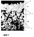
- Fig. 1 shows a microscopic micrograph of the interface between the Material layers A and B of a composite body according to the invention.
- the gray ones Areas (1) are SiC particles which are approximately uniform over the entire Neckline are distributed.
- Material layer A surrounding material B is for flat components
- the composite bodies are made by the metal-liquid infiltration of Porous green bodies containing SiC, carbon and nitride.
- the porous carbon-containing green body In the manufacture of the porous carbon-containing green body, one is first Mixture of the solids containing silicon carbide, nitrides, if appropriate Carbon and organic binder made. This mixture is made according to the usual processes in the ceramic industry (including pressing, injection molding, Slip) brought into shape, the curing of the organic binder for the Strength of the resulting body is responsible. The hardened body will followed by a temperature treatment in the range of approx. 650 to 1600 ° C, preferably 1000 ° C, carbonized. According to the invention, the organic binder carbonizable, that is, when heated under non-oxidizing conditions the binder does not evaporate completely, but it forms Carbon residue. The resulting body, the green body, exists now from the solids used, especially the ceramic particles held together by a binding phase made of pyrolytically produced carbon become.
- the composition of the starting mixture is preferably chosen so that the Mass fraction of silicon carbide in the porous carbon-containing green body is at least 50%, preferably at least 65%.
- the mass fraction of Carbon, from carbonized binder and solids used, is typically above 4% and preferably above 8%, the mass fraction nitride content above 1%, preferably above 3% and particularly preferably between 3 and 12%.
- the nitrides are particularly selected from at least one of the nitrides of the following elements: Ti, Zr, Si, B and Al.
- the carbon material used as a solid is selected from the group Coal, coke, natural graphite, technical graphite, carbonized organic material, Carbon fibers, glassy carbon and coking products. Particularly suitable are natural graphite or synthetic graphite.
- a major advantage of the invention is that almost on expensive carbon fibers can be completely or completely dispensed with.
- step b) the supply of a molten metal, a carbide-forming metal is in infiltrates the porous green body.
- the infiltration is caused by the capillary action and the chemical reaction between the free one that occurs during infiltration Carbon of the green body supported with the carbide-forming metal.
- the infiltration takes place at reduced pressure or vacuum, at Temperatures of approx. 150 ° C above the melting temperature of the Infiltration metal.
- Silicon alloys typically made of Si, are preferred as the infiltration metal and at least one of the elements Ti, Fe, Cr and Mo, and particularly preferred technically pure Si used.
- the Mass fraction of infiltration metal supplied by the infiltration inside the composite material according to the invention is typically below 1%, and the mass fraction of by that Infiltration metal newly formed metal carbide below 3%.
- the chemical composition and the porosity of the Green body and the infiltration metal range chosen so that the green body only is partially infiltrated.
- the depth of infiltration can be specifically controlled.
- the nitrides wetting the green body with the molten Silicon deteriorates.
- the depth of infiltration of the silicon-containing melt reduces and the degree of implementation of the green body controlled.
- step c) the conversion of at least part of the free carbon takes place the infiltration metal instead. Especially about temperature and process time sales are controlled.
- a dense ceramic is formed in material layer A.
- material layer B where almost none Infiltration metal arrives at the temperature of step c) Sintering reaction takes place between the ceramic particles, which among other things leads to a mechanical stabilization of the material layer leads.
- the firmness (Breaking strength) only has to be so high that material B can be handled and does not disintegrate easily.
- the actual mechanical stabilization of the Material layer B takes place via the firmly attached material layer A.
- the Strength of layer B can be increased if the mixture for the green body Sintering aids are added, preferably Si compounds or powders contain.
- the molten metal is usually over wicks or over Metal powder fillings fed. Typically, the metal infiltration takes place in the essentially over the entire surface, so that the material layer A a closed material surface results. Become plate-shaped green bodies used, results in a component that in the direction of the surface normal, the preferred direction of the ballistic threat, the layer sequence of the Material layers A B A has.
- the mechanical stability of the material layer B can be improved without the properties according to the invention, which are similar to a loose powder bed, being lost if the pores of the material B are additionally filled with a soft material.
- This can be achieved, for example, by melt infiltration with a thermoplastic polymer or by liquid infiltration with a polymer resin.
- the pores are preferably filled at least 30% with polyolefins or epoxy resins.
- the pores are infiltrated with adhesives which are particularly suitable for bonding to a backing. Backing materials made from aramid fibers are particularly suitable.
- the composite body in particular the material layer B, with a light metal, in particular Al, infiltrated.
- the residual porosity lies in the Layer B preferably below 15%.
- the filling of the pores of the material layer B with a polymer can be special advantageous for gluing with a backing, in particular a backing Fiber mats or fabrics can be used.
Abstract
Description
Die Erfindung betrifft keramische Verbundkörper umfassend mindestens zwei Schichten, insbesondere für Schutzpanzerungen , die für zivile und militärische Einsatzgebiete geeignet sind. Insbesondere betrifft die Erfindung Körper aus einem überwiegend Siliciumcarbid (SiC) enthaltenden mehrschichtigen Werkstoffverbund, mit einer im wesentlichen aus in einer Matrix aus freiem Silicium (Si) gebundenem SiC bestehenden außenliegenden Werkstoffschicht und einer innenliegenden Werkstoffschicht enthaltend lose gebundenes SiC- Keramikpulver, sowie ein Verfahren zu deren Herstellung und Verwendungen dieser Verbundkörper.The invention relates to ceramic composite bodies comprising at least two Layers, especially for protective armor, for civil and military Areas of application are suitable. In particular, the invention relates to a single body mainly multilayer composite material containing silicon carbide (SiC), with one essentially bonded in a matrix of free silicon (Si) SiC existing external material layer and an internal one Material layer containing loosely bound SiC ceramic powder, as well as a Process for their production and uses of these composite bodies.
Für Schutzpanzerungen gegen die ballistische Einwirkung von Projektilen werden je nach Einsatzgebiet unterschiedliche Anforderungen an die geschossbrechende Wirkung, Multihit-Tauglichkeit, Bauteilgeometrie oder Bauteilgewicht gestellt.Protective armor against the ballistic impact of projectiles are used Depending on the area of application, different requirements for the projectile Effect, multi-hit suitability, component geometry or component weight.
Im zivilen Bereich konzentriert sich der Einsatz insbesondere auf den Personenschutz, gepanzerte Limousinen und Schutzwesten. Die Anforderungen an die geschossbrechende Wirkung sind nicht so hoch, da in diesem Bereich selten mit schweren Waffen beziehungsweise mittleren und großen Kalibern gerechnet werden muss. Hohe Anforderungen werden unter anderem an Bauteilgeometrie und Bauteilgewicht gestellt. Es werden komplex geformte Teile verlangt, gekoppelt mit der Forderung nach einer möglichst geringen Bauteildicke oder Einbautiefe und geringem Gewicht. Die Distanz zur Bedrohung ist meist sehr kurz und kann bei nur wenigen Metern liegen. Dies führt im Falle des häufig auftretenden Mehrfachbeschusses (hier als "Multihit" bezeichnet) zu nahe beieinander liegenden Treffern. Daraus ergeben sich höchste Anforderungen an die Multihit-Tauglichkeit der Schutzpanzerung.In the civilian sector, the focus is particularly on the Personal protection, armored limousines and protective vests. The requirements for The bullet-breaking effects are not as high, as they are rarely used in this area heavy weapons or medium and large calibers got to. Among other things, high demands are placed on component geometry and Component weight set. Complex shaped parts are required, coupled with the requirement for the smallest possible component thickness or installation depth and light weight. The distance to the threat is usually very short and can only be a few meters. This results in the case of the common one Multiple shots (referred to here as "multihit") are too close together Hits. This results in the highest requirements for multi-hit suitability the protective armor.
Im militärischen Bereich ist von einer Bedrohung durch Hochgeschwindigkeits- und großkalibrige Geschosse sowie Explosivgeschosse auszugehen. Obwohl die Anforderungen an die Bauteildicke und Einbautiefe geringer sind als im zivilen Bereich, ist auch hier ein geringes spezifisches Gewicht des Panzerungsmaterials von entscheidender Bedeutung, denn aufgrund der extrem hohen Anforderungen an die energieabsorbierende Wirkung muss das Schutzpanzerungs-Bauteil im allgemeinen sehr dick ausgeführt werden.In the military field is threatened by high-speed and large caliber bullets and explosive bullets. Although the Component thickness and installation depth requirements are lower than in civilian applications Range, here too is a low specific weight of the armor material of crucial importance, because of the extremely high requirements the protective armor component in the generally run very thick.
Die großen Distanzen zu den Zielobjekten bedingen im allgemeinen große Trefferabstände. Daher werden hier geringere Anforderungen an die Multihit-Tauglichkeit gestellt.The large distances to the target objects generally require long distances Hits distances. Therefore, there are fewer requirements for multi-hit suitability posed.
Zur Panzerung im militärischen Bereich werden heute häufig flache Platten als Zusatzpanzerung für Land- und Wasserfahrzeuge sowie für Helikopter, Container, Behälter, Unterstände und Feldbefestigungen eingesetzt.Flat plates are often used as armor for military purposes Additional armor for land and water vehicles as well as for helicopters, containers, Containers, shelters and field fortifications used.
Eine Panzerung aus einer oder mehreren Panzerstahlplatten wird üblicherweise so behandelt, dass zumindest die der Bedrohung zugewandte Seite extrem hart und damit geschossbrechend wird. Die der Bedrohung abgewandte Seite ist duktiler oder zäher ausgestaltet, um durch eine Materialdeformation die Energie des Geschosses zu absorbieren. Hieraus ergibt sich auch der für Panzerplatten aus anderen Materialien typische Aufbau.Armor consisting of one or more armored steel plates is usually like this treats that at least the side facing the threat is extremely hard and so that the bullet breaks. The side facing away from the threat is more ductile or more visibly designed to withstand the energy of the projectile through a material deformation to absorb. This also results in that for armored plates from others Materials typical structure.
Gegenüber den Metallen weisen die keramischen Werkstoffe den Vorteil höherer Härte und geringeren spezifischen Gewichts auf. Da die monolithische Keramik beim Beschuss ein typisches Sprödbruchverhalten zeigt, bersten Keramikplatten (monolithische Keramik) unter Bildung vieler grober bis feinster Splitter. Die Verwendung von Keramikplatten ohne zusätzliches Backing (Stützmaterial und Splitterfang) auf der dem Eintritt des Geschosses abgewandten Seite ist aufgrund des Splitterabgangs beim Beschuss nicht sinnvoll. Durch den Beschuss wird im allgemeinen die jeweilige Keramikplatte völlig zerstört. Ein Mehrfachbeschuss (Multi-Hit) kann daraufhin nicht mehr gehalten werden.Compared to metals, ceramic materials have the advantage of being higher Hardness and lower specific weight. Since the monolithic ceramic at Shelling shows a typical brittle fracture behavior, ceramic plates burst (monolithic ceramics) with formation of many coarse to very fine fragments. The Use of ceramic plates without additional backing (support material and Fragmentation) on the side facing away from the entry of the projectile is due the splinter exit does not make sense when fired at. Due to the shelling in generally completely destroyed the respective ceramic plate. A multiple bombardment (multi-hit) can then no longer be held.
Eine Panzerung mit keramischen Werkstoffen besteht aus diesen Gründen bevorzugt aus zwei Schichten. Die Frontplatte aus möglichst monolithischer Keramik hat die Aufgabe, das Rest-Geschoss zu deformieren und gegebenenfalls den Hartkern zu brechen. Eine hinter der Keramikplatte angebrachte, verformbare Armierung, das Backing, hat die Aufgabe das Geschoss, Geschosstrümmer und Keramiksplitter aufzufangen oder zu absorbieren und die restliche Keramikplatte zu stabilisieren. Sie wird im folgenden auch Absorberschicht genannt. Das Backing besteht im allgemeinen aus hochdehnbaren und reißfesten Geweben (Aramidfasergewebe, HDPE-Gewebe, etc.), Metall oder Kunststoffen.Armor with ceramic materials exists for these reasons preferably of two layers. The front plate made of monolithic ceramics has the task of deforming the remaining floor and, if necessary, the Breaking hard core. A deformable one attached behind the ceramic plate Armoring, the backing, has the task of projectile, bullet debris and Ceramic fragments to catch or absorb and the remaining ceramic plate to stabilize. It is also called the absorber layer below. The backing generally consists of highly stretchable and tear-resistant fabrics (Aramid fiber fabric, HDPE fabric, etc.), metal or plastics.
Moderne Werkstoffkonzepte führen zu faserverstärkten Verbundwerkstoffen, die Bereiche aus monolithischer Keramik (Geschossbrecher) und faserverstärkter Keramik aufweisen (Absorberschicht), wie zum Beispiel in der EP-A 0 376 794 beschrieben. Als Nachteil dieser Konzepte erweist sich im allgemeinen der hohe Preis und die geringe Verfügbarkeit geeigneter Fasern für faserverstärkte Keramiken. So sind für das üblicherweise angewandte Sinterverfahren zur Herstellung von faserverstärkter Keramik nur relativ teure Kohlenstofffasern von technischer Bedeutung.Modern material concepts lead to fiber-reinforced composite materials that Areas made of monolithic ceramics (bullet breakers) and fiber-reinforced Have ceramic (absorber layer), such as in EP-A 0 376 794 described. The disadvantage of these concepts is generally the high one Price and the low availability of suitable fibers for fiber-reinforced ceramics. So are for the commonly used sintering process for the production of fiber-reinforced ceramics only relatively expensive carbon fibers of technical Importance.
Ein weiterer Ansatz, die projektil- und splitterabsorbierende Wirkung durch Keramikmaterial zu erreichen, ist in der EP-A 0 287 918 ausgeführt. In einer der aufgeführten Varianten wird eine Mehrschichtpanzerplatte beschrieben, die aus einer konventionellen Keramikplatte als Frontplatte und einer dahinter liegenden Absorberplatte aus sogenannter chemisch gebundener Keramik besteht. Die chemisch gebundene Keramik besteht aus harten Füllstoffen, wie beispielsweise Fasern oder Keramik-Pulver, und einer Bindephase (oder Matrix) aus mit organischen oder anorganischen Polymeren modifizierten Zementen, die bei niedrigen Temperaturen aushärten. Die harten Füllstoffe führen zu einer Abstumpfung, Umlenkung und Zertrümmerung des Projektils.Another approach that uses the projectile and splinter-absorbing effect Reaching ceramic material is described in EP-A 0 287 918. In one of the listed variants, a multilayer armor plate is described, which consists of a conventional ceramic plate as a front plate and one behind it Absorber plate consists of so-called chemically bound ceramics. The Chemically bonded ceramics consist of hard fillers such as Fibers or ceramic powder, and a binding phase (or matrix) made of with organic or inorganic polymers modified cements, which harden at low temperatures. The hard fillers lead to one Blunting, deflection and destruction of the projectile.
Die Herstellung von Mehrschichtpanzerplatten mit komplexer Geometrie und fester chemischer Verbindung zwischen den zwei Materialschichten ist nach diesem Verfahren allerdings sehr aufwändig.The production of multi-layer armor plates with complex geometry and solid chemical bond between the two layers of material is after this However, the process is very complex.
Gegenüber diesem Stand der Technik ist es Aufgabe der Erfindung, einen Keramikverbundkörper mit einer geschossbrechenden Frontschicht und einer fest mit dieser verbundenen Absorberschicht mithilfe eines kostengünstigen Herstellungsverfahrens, das auch komplexe Bauteilgeometrien zulässt, verfügbar zu machen. Compared to this prior art, it is an object of the invention, a Ceramic composite body with a bullet-breaking front layer and one with this connected absorber layer using an inexpensive Manufacturing process that also allows complex component geometries available do.
Diese Aufgabe wird erfindungsgemäß gelöst durch einen Verbundkörper, der mindestens zwei Schichten umfaßt, dadurch gekennzeichnet, daß eine außen liegende geschossbrechende Keramikschicht (Frontplatte) im wesentlichen aus einem Carbid und einem carbidbildenden Metall, bevorzugt SiC und Si (Werkstoffschicht A) besteht, und eine mit dieser fest verbundene innen liegende Schicht (Werkstoffschicht B), die schwach oder lose gebundenes Keramikpulver enthält, das im wesentlichen aus SiC besteht.This object is achieved by a composite body that comprises at least two layers, characterized in that one outside lying bullet-breaking ceramic layer (front panel) essentially a carbide and a carbide-forming metal, preferably SiC and Si (Material layer A) exists, and an internal one firmly connected to it Layer (material layer B), the weakly or loosely bound ceramic powder contains, which consists essentially of SiC.
Weiterhin wird ein Verfahren zur Herstellung eines solchen Verbundkörpers angegeben, bei dem der mehrschichtige Verbundwerkstoff durch die Flüssiginfiltration eines porösen Grünkörpers aus Keramikpartikeln und Kohlenstoffmaterial durch ein carbidbildendes Metall, insbesondere Siliciummetall, hergestellt wird, wobei durch die Flüssigmetallinfiltration in einem einzigen gemeinsamen Verfahrensschritt sowohl die außen liegende Keramikschicht aus Carbid und carbidbildendem Metall, bevorzugt SiC und Si (Werkstoffschicht A), als auch die innen liegende Schicht aus schwach oder lose gebundenem Keramikpulver aus überwiegend SiC (Werkstoffschicht B) gebildet wird, sowie beide Schichten fest miteinander chemisch verbunden werden.Furthermore, a method for producing such a composite body specified, in which the multi-layer composite material by the Liquid infiltration of a porous green body made of ceramic particles and Carbon material through a carbide-forming metal, in particular silicon metal, is made by liquid metal infiltration in one common process step from both the outer ceramic layer Carbide and carbide-forming metal, preferably SiC and Si (material layer A), as also the inner layer of weakly or loosely bound ceramic powder predominantly SiC (material layer B) is formed, as well as both layers firmly are chemically linked together.
Der Erfindung liegt die Erkenntnis zugrunde, dass pulvrige oder partikelförmige Keramik, ähnlich einer Sandschüttung, ein sehr günstiges Absorptionsverhalten gegenüber ballistischer Einwirkung zeigt, sofern das pulvrige Material mechanisch stabilisiert, beziehungsweise zusammengehalten wird. Dieser Zusammenhalt wird erfindungsgemäß durch die chemisch fest verbundene Keramikschicht (Werkstoffschicht A), sowie auch durch den während der Metallschmelzinfiltration stattfindenden Sinterprozess der Keramikmischung des Grünkörpers im Bereich der Werkstoffschicht B erreicht.The invention is based on the knowledge that powdery or particulate Ceramic, similar to a sand fill, has a very favorable absorption behavior against ballistic effects, provided the powdery material is mechanical is stabilized or held together. This cohesion will according to the invention by the chemically firmly bonded ceramic layer (Material layer A), as well as by the during the metal melt infiltration sintering process of the ceramic mixture of the green body in the area of Material layer B reached.
Der erfindungsgemäße Verbundkörper umfaßt daher mindestens zwei Schichten,
eine außen liegende Werkstoffschicht A, die Phasen aus einem carbidbildenden
Metall und dem Carbid dieses Metalls enthält, bevorzugt reaktionsgebundenes
Siliciumcarbid (SiC) und Silicium, auch als SiSiC bezeichnet, und eine
dahinterliegende Werkstoffschicht B, die durch Sintern lose gebundenes SiC-Keramikpulver
oder -Partikel enthält, sowie gegebenenfalls dahinter angeordnete
weitere Schichten, insbesondere aus dem Werkstoff A oder aus faserhaltigem
Backing. Durch diese weitere Schichten wird die energieabsorbierende Wirkung der
Panzerung zusätzlich verbessert.
Unter lose gebundenem Keramikpulver, oder partikeln ist insbesondere Material zu
verstehen, dessen Festigkeit um mindestens 20% unterhalb derjenigen des Materials
der Werkstoffschicht A liegt.The composite body according to the invention therefore comprises at least two layers, an outer material layer A, which contains phases made of a carbide-forming metal and the carbide of this metal, preferably reaction-bonded silicon carbide (SiC) and silicon, also referred to as SiSiC, and a material layer B behind it, which through Sintering contains loosely bound SiC ceramic powder or particles, and optionally further layers arranged behind them, in particular made of material A or of fiber-containing backing. These additional layers further improve the energy-absorbing effect of the armor.
Loosely bound ceramic powder or particles is to be understood in particular as material whose strength is at least 20% below that of the material of material layer A.
Beim bevorzugten Verfahren der Flüssigmetallinfiltration -bevorzugt mit einer Siliciumschmelze- wird in der Werkstoffschicht A durch Reaktion des carbidbildenden Metalls mit Kohlenstoff eine Keramik gebildet, die neben sehr hoher Härte eine gute Bruchzähigkeit oder Schadenstoleranz aufweist. Hierdurch wird das für den Mehrfachbeschuss schädliche keramische Sprödbruchverhalten in vorteilhafter Weise unterdrückt. Als Infiltrationsmetall wird bevorzugt eine Legierung verwendet, die mindestens einen Massenanteil von 50 % Silicium enthält, besonders bevorzugt ist technisches Silicium oder reines Silicium. Bei der Infiltration mit einer siliciumhaltigen Legierung der Metalle, Fe, Cr, oder Ni bildet sich aus dem im Vorläufer der Werkstoffschicht A enthaltenen Kohlenstoff bevorzugt Siliciumcarbid. Bei der Infiltration mit einer Titan-Silicium-Legierung bildet sich aus dem Kohlenstoff bevorzugt Titancarbid neben Siliciumcarbid.In the preferred method of liquid metal infiltration, preferably with a Silicon melt - is in the material layer A by reaction of the carbide-forming Metal with carbon formed a ceramic, which in addition to very high hardness is a good one Exhibits fracture toughness or damage tolerance. This will make it for the Multiple bombardment harmful ceramic brittle fracture behavior in advantageous Suppressed way. An alloy is preferably used as the infiltration metal, which contains at least a mass fraction of 50% silicon, is particularly preferred is technical silicon or pure silicon. When infiltrating with a silicon-containing alloy of metals, Fe, Cr, or Ni forms from the im Carbon precursors of material layer A preferably contain silicon carbide. When infiltrated with a titanium-silicon alloy, the carbon forms preferably titanium carbide in addition to silicon carbide.
Die in der Werkstoffschicht B enthaltenen Partikel aus Siliciumcarbid und Nitriden werden bei der Temperatur der Infiltration mit dem flüssigen Metall an den Berührungsstellen zusammengesintert, wobei ein loses Gefüge mit Poren entsteht. Die nichtflüchtigen Pyrolyseprodukte des organischen Binders der Rohstoffmischung tragen ebenso zur Festigkeit der Werkstoffschicht B bei.The particles of silicon carbide and nitrides contained in material layer B. are at the temperature of infiltration with the liquid metal to the Contact points sintered together, creating a loose structure with pores. The non-volatile pyrolysis products of the organic binder of the raw material mixture also contribute to the strength of the material layer B.
Die Werkstoffschicht A enthält bevorzugt einen Massenanteil von mindestens 70 % von SiC-Partikeln, die in einer Matrix aus freiem Silicium eingebettet sind. Bevorzugt liegt der Massenanteil an SiC oberhalb von 75 % und besonders bevorzugt oberhalb von 85 %. Dabei liegt der Massenanteil an freiem Silicium, worunter auch alle Silicium-Mischphasen mit weiteren metallischen Elementen verstanden werden sollen, oberhalb von 2,8 %. Bevorzugt liegt der Massenanteil an freiem Silicium im Bereich von 3 bis 21 % und besonders bevorzugt im Bereich von 3 bis 15 %. Die Werkstoffschicht A wird so aufgebaut, dass eine möglichst hohe Härte erreicht wird, was beispielsweise durch eine möglichst hohe Dichte, idealerweise die theoretische Dichte, erreicht werden kann. Bevorzugt liegt daher die Porosität (Volumenanteil der Poren am gesamten Volumen) der Werkstoffschicht A unter 20 % oder die Dichte bei mindestens 2,1 g/cm3 und besonders bevorzugt liegt die Porosität unterhalb von 10 % beziehungsweise die Dichte oberhalb von 2,2 g/cm3. Typischerweise weist der Werkstoff A noch freien Kohlenstoff, sowie gegebenenfalls keramische Zuschlagstoffe in Massenanteilen von ca. 0,5 bis 15 % auf. Als in bevorzugter Weise zusätzlich eingesetzte keramische Zuschlagstoffe werden erfindungsgemäß besonders harte Keramiken auf Nitridbasis eingesetzt. Zu diesen zählen insbesondere die Nitride der Elemente Si, Ti, Zr, B und Al.The material layer A preferably contains a mass fraction of at least 70% of SiC particles which are embedded in a matrix of free silicon. The mass fraction of SiC is preferably above 75% and particularly preferably above 85%. The mass fraction of free silicon, which should also include all silicon mixed phases with other metallic elements, is above 2.8%. The mass fraction of free silicon is preferably in the range from 3 to 21% and particularly preferably in the range from 3 to 15%. The material layer A is built up in such a way that the highest possible hardness is achieved, which can be achieved, for example, by the highest possible density, ideally the theoretical density. The porosity (volume fraction of the pores in the total volume) of the material layer A is therefore preferably less than 20% or the density is at least 2.1 g / cm 3, and the porosity is particularly preferably less than 10% or the density above 2.2 g / cm 3 . Typically, material A still has free carbon and, if appropriate, ceramic additives in mass fractions of about 0.5 to 15%. According to the invention, particularly hard ceramics based on nitride are used as the preferred ceramic additives. These include in particular the nitrides of the elements Si, Ti, Zr, B and Al.
Die mittlere Partikelgröße des SiC,das sowohl für die Werkstoffschicht A als auch für die Werkstoffschicht B eingesetzt werden kann, liegt typischerweise im Bereich von 20 bis 750 µm. Da im allgemeinen verfahrensbedingt zunächst ein homogener Grünkörper (Vorkörper der Metallinfiltration) aus den Keramikpulvern hergestellt wird, unterscheiden sich die Partikelgrößen in den Werkstoffschichten A und B nur unwesentlich. Ebenso ist es aber auch möglich, verschiedene Partikelgrößen für die Schichten vorzusehen, wobei dann die Werkstoffschicht A bevorzugt feineres Material als die Werkstoffschicht B enthält. Besonders bevorzugt liegt dann die mittlere Partikelgröße in der Schicht A unterhalb von 50 µm und in der Schicht B oberhalb von 50 µm.The average particle size of the SiC, which applies to both material layer A and material layer B can typically be used in the range of 20 to 750 µm. Since the process is generally a homogeneous one Green body (preform of metal infiltration) is made from the ceramic powders, the particle sizes in material layers A and B only differ immaterial. However, it is also possible to use different particle sizes for the Provide layers, in which case the material layer A is preferably finer Contains material as the material layer B. The is then particularly preferably average particle size in layer A below 50 µm and in layer B above 50 µm.
Auch die Werkstoffschicht B ist bevorzugt zum überwiegenden Teil aus SiC-Partikeln aufgebaut. Bevorzugt liegt der Massenanteil an SiC-Partikeln oberhalb von 70 % und besonders bevorzugt oberhalb von 90 %. Auch der Gehalt an keramischen Zuschlagstoffen liegt bei vergleichbaren Anteilen wie in der Schicht A. Bevorzugt enthält die Werkstoffschicht B zumindest eines der Nitride der Elemente Si, Ti, Zr, B und Al in Massenanteilen von 0,05 bis 15 %. Im wesentlichen Unterschied zum Werkstoff A ist in der Werkstoffschicht B die Keramik, beziehungsweise deren Keramikpartikel, nicht durch Silicium reaktionsgebunden, es ist nahezu keine Matrix aus Silicium oder einer Siliciumlegierung vorhanden. Der Massenanteil an freiem Silicium beziehungsweise an Silicium/Metall-Phasen liegt typischerweise unterhalb von 5 %, bevorzugt unterhalb 2,5 % und besonders bevorzugt unterhalb von 1 %. The material layer B is also preferably predominantly made of SiC particles built up. The mass fraction of SiC particles is preferably above 70% and particularly preferably above 90%. Also the content of ceramic Aggregates are in comparable proportions as in layer A. Preferred contains the material layer B at least one of the nitrides of the elements Si, Ti, Zr, B and Al in mass proportions of 0.05 to 15%. The main difference to Material A in material layer B is ceramic, or its Ceramic particles, not bonded by silicon, it is almost no matrix made of silicon or a silicon alloy. The mass fraction of free Silicon or silicon / metal phases is typically below of 5%, preferably below 2.5% and particularly preferably below 1%.
Die Keramikpartikel in der Werkstoffschicht B sind nur schwach gebunden, teils über Kohlenstoff-Bindephasen, teils direkt über Sinterbrücken untereinander. Die Werkstoffschicht B weist daher eine vergleichsweise hohe Porosität auf, die typischerweise von 5 % bis 35 % reicht, und bevorzugt im Bereich von 12 bis 27 % liegt.The ceramic particles in the material layer B are only weakly bound, some over Carbon binding phases, sometimes directly with each other via sinter bridges. The Material layer B therefore has a comparatively high porosity typically ranges from 5% to 35%, and preferably in the range from 12 to 27% lies.
Die Dichte der Werkstoffschicht B liegt im allgemeinen unterhalb von 2,55 g/cm3 , bevorzugt unterhalb 2,05 g/cm3 und besonders bevorzugt unterhalb von 1,96 g/cm3. Typischerweise liegt die Porosität in der Werkstoffschicht B um mindestens 7 % höher als in der Werkstoffschicht A.The density of the material layer B is generally below 2.55 g / cm 3 , preferably below 2.05 g / cm 3 and particularly preferably below 1.96 g / cm 3 . The porosity in material layer B is typically at least 7% higher than in material layer A.
Für die erfindungsgemäße Wirkung der Werkstoffschicht B ist die nur lose Bindung zwischen den Keramikpartikeln wesentlich. Unter anderem wird hierdurch die für den Sprödbruch typische Rissausbreitung durch weite Bereiche eines zusammenhängenden Werkstückteiles verhindert, wobei dennoch die Härte der Keramikpartikel genutzt wird. Diese Wirkung wird ebenso erreicht, wenn die Poren in dieser Schicht durch gegenüber der Keramik deutlich weicheres Material gefüllt sind.For the effect of the material layer B according to the invention, the only loose bond is between the ceramic particles essential. Among other things, this is for the Typical crack propagation through large areas of a brittle fracture coherent workpiece part prevented, while the hardness of Ceramic particles is used. This effect is also achieved when the pores in This layer is filled with material that is significantly softer than the ceramic.
In einer weiteren vorteilhaften Ausgestaltung der Erfindung sind daher die Zwischenräume zwischen den Keramikpartikeln in der Werkstoffschicht B mit einem weichen Material gefüllt. Üblicherweise wird als weiches Material ein Kunststoff oder ein Metall eingesetzt, wobei das Metall eine Härte auf der Mohs-Skala von höchstens 5 aufweist. Geeignet sind insbesondere thermoplastische Polymere, Harze, Klebstoffe, Elastomere oder Aluminium. Bevorzugt ist dann zumindest die Hälfte des Raums, der zwischen den keramischen Partikeln gebildet wird, mit dem weichen Material gefüllt.In a further advantageous embodiment of the invention, therefore Spaces between the ceramic particles in the material layer B with a soft material filled. A plastic or is usually used as the soft material a metal is used, the metal having a hardness on the Mohs scale of at most 5 has. Thermoplastic polymers, resins, Adhesives, elastomers or aluminum. Then at least half of the Space that is formed between the ceramic particles with the soft Material filled.
Die Anwendung der erfindungsgemäßen Verbundkörper liegt im Bereich der Schutzpanzerungen, insbesondere gegen ballistische Einwirkung. Aufgrund der guten thermischen Eigenschaften, insbesondere des hohen Schmelz- oder Zersetzungspunktes von SiC, zeigt der Verbundwerkstoff auch eine gute Eignung als Panzerungsmaterial im Tresor- und Schutzgebäudebau. The application of the composite body according to the invention is in the range of Protective armor, especially against ballistic effects. Due to the good thermal properties, especially the high melting or Decomposition point of SiC, the composite material also shows good suitability as Armor material in the vault and protective building.
Bauteile aus den erfindungsgemäßen Verbundkörpern werden üblicherweise so ausgelegt, dass die gesamte Dicke der Werkstoffschichten A und B im Bereich von 6 bis 300 mm liegt. Auch weitere Schichten, insbesondere aus dem Werkstoff A oder faserhaltigem Backing können hinter der Schicht aus dem Werkstoff B angeordnet sein. Die Schichtdicke des Werkstoffs A liegt üblicherweise oberhalb von 1 mm, für Panzerplatten bevorzugt oberhalb von 3 mm. Das Schichtdickenverhältnis der Werkstoffschichten A und B liegt typischerweise unterhalb von 1:50, bevorzugt unterhalb von 1:10, wobei hier nur die der Beschußseite zugewandte Frontschicht aus dem Werkstoff A und die darauf folgende Schicht aus dem Werkstoff B zu verstehen sind.Components from the composite bodies according to the invention are usually so designed that the total thickness of the material layers A and B in the range of 6 up to 300 mm. Also other layers, in particular from material A or fibrous backing can be placed behind the layer of material B. his. The layer thickness of material A is usually above 1 mm, for Armor plates preferably above 3 mm. The layer thickness ratio of Material layers A and B are typically below 1:50, preferably below 1:10, here only the front layer facing the bombardment side from material A and the subsequent layer from material B. are understand.
Die Werkstoffschicht A geht in die Werkstoffschicht B über, wobei der Übergang im allgemeinen durch eine deutliche Abnahme des Gehaltes an Silicium in der Matrix zu erkennen ist.Material layer A merges into material layer B, the transition in generally due to a significant decrease in the silicon content in the matrix is recognizable.
Fig. 1 zeigt eine mikroskopische Schliff-Aufnahme der Grenzfläche zwischen den Werkstoffschichten A und B eines erfindungsgemäßen Verbundkörpers. Die grauen Bereiche (1) sind SiC-Partikel, welche annähernd gleichmäßig über den gesamten Ausschnitt verteilt sind. In der oberen Hälfte (A), die dem Werkstoff A entspricht, sind die SiC-Bereiche durch eine kontinuierliche helle Phase (2) verbunden. Dies ist die Matrix aus Silicium. Die untere Hälfte (B), die dem Werkstoff B entspricht, weist statt der Matrix Poren auf (schwarze Bereiche, 3). Die weiteren Bestandteile aus Kohlenstoff oder Nitridpartikeln lassen sich in dieser Darstellung nicht von den anderen Materialien unterscheiden.Fig. 1 shows a microscopic micrograph of the interface between the Material layers A and B of a composite body according to the invention. The gray ones Areas (1) are SiC particles which are approximately uniform over the entire Neckline are distributed. In the upper half (A), which corresponds to material A. the SiC areas connected by a continuous bright phase (2). this is the Silicon matrix. The lower half (B), which corresponds to material B, takes place of the matrix pores (black areas, 3). The other ingredients In this representation, carbon or nitride particles cannot be separated from the differentiate other materials.
Aufgrund der verfahrensbedingt einfachen Herstellbarkeit eines allseitig mit einer Werkstoffschicht A umgebenen Werkstoffs B ist für flächige Bauteile die Schichtabfolge einer Frontplatte aus dem Werkstoff A, einer Absorberzone aus dem Werkstoff B und Rückenplatte (oder Backing) aus dem Werkstoff A besonders bevorzugt.Because of the process-related ease of manufacture, one with all sides Material layer A surrounding material B is for flat components Layer sequence of a front panel made of material A, an absorber zone made of Material B and back plate (or backing) made of material A in particular prefers.
Erfindungsgemäß werden die Verbundkörper durch die Metall-Flüssiginfiltration von SiC-, Kohlenstoff- und Nitridhaltigen porösen Grünkörpern hergestellt. According to the invention, the composite bodies are made by the metal-liquid infiltration of Porous green bodies containing SiC, carbon and nitride.
Das Verfahren weist die folgenden wesentlichen Prozeßschritte auf:
Bei der Herstellung des porösen kohlenstoffhaltigen Grünkörpers wird zunächst eine Mischung der Feststoffe, enthaltend Siliciumcarbid, Nitride, gegebenenfalls Kohlenstoff und organischem Binder hergestellt. Diese Mischung wird nach den üblichen Verfahren der keramischen Industrie (unter anderem Pressen, Spritzgießen, Schlickern) in Form gebracht, wobei die Aushärtung des organischen Binders für die Festigkeit des resultierenden Körpers verantwortlich ist. Der gehärtete Körper wird hierauf durch eine Temperaturbehandlung im Bereich von ca. 650 bis 1600 °C, bevorzugt 1000 °C, carbonisiert. Erfindungsgemäß ist der organische Binder carbonisierbar, das heißt, bei Erhitzen unter nicht oxidierenden Bedingungen wird der Binder nicht vollständig verflüchtigt, sondern es bildet sich ein Kohlenstoffrückstand aus. Der resultierende Körper, der Grünkörper, besteht nunmehr aus den eingesetzten Feststoffen, insbesondere den Keramikpartikeln, die von einer Bindephase aus pyrolytisch erzeugtem Kohlenstoff zusammengehalten werden.In the manufacture of the porous carbon-containing green body, one is first Mixture of the solids containing silicon carbide, nitrides, if appropriate Carbon and organic binder made. This mixture is made according to the usual processes in the ceramic industry (including pressing, injection molding, Slip) brought into shape, the curing of the organic binder for the Strength of the resulting body is responsible. The hardened body will followed by a temperature treatment in the range of approx. 650 to 1600 ° C, preferably 1000 ° C, carbonized. According to the invention, the organic binder carbonizable, that is, when heated under non-oxidizing conditions the binder does not evaporate completely, but it forms Carbon residue. The resulting body, the green body, exists now from the solids used, especially the ceramic particles held together by a binding phase made of pyrolytically produced carbon become.
Die Zusammensetzung der Ausgangsmischung wird bevorzugt so gewählt, dass der Massenanteil an Siliciumcarbid im porösen kohlenstoffhaltigen Grünkörper mindestens 50 %, bevorzugt mindestens 65 % beträgt. Der Massenanteil an Kohlenstoff, aus carbonisiertem Binder und eingesetzten Feststoffen, liegt typischerweise oberhalb von 4 % und bevorzugt oberhalb von 8 %, der Massenanteil an Gehalt an Nitriden oberhalb von 1 %, bevorzugt oberhalb von 3 % und besonders bevorzugt zwischen 3 und 12 %. Die Nitride sind insbesondere ausgewählt aus mindestens einem der Nitride der folgenden Elemente: Ti, Zr, Si, B und Al. The composition of the starting mixture is preferably chosen so that the Mass fraction of silicon carbide in the porous carbon-containing green body is at least 50%, preferably at least 65%. The mass fraction of Carbon, from carbonized binder and solids used, is typically above 4% and preferably above 8%, the mass fraction nitride content above 1%, preferably above 3% and particularly preferably between 3 and 12%. The nitrides are particularly selected from at least one of the nitrides of the following elements: Ti, Zr, Si, B and Al.
Das als Feststoff eingesetzte Kohlenstoffmaterial ist ausgewählt aus der Gruppe Kohle, Koks, Naturgraphit, technischer Graphit, carbonisiertes organisches Material, Kohlenstoffasern, Glaskohlenstoff und Verkokungsprodukten. Besonders geeignet sind natürlicher Graphit oder synthetischer Graphit.The carbon material used as a solid is selected from the group Coal, coke, natural graphite, technical graphite, carbonized organic material, Carbon fibers, glassy carbon and coking products. Particularly suitable are natural graphite or synthetic graphite.
Ein wesentlicher Vorteil der Erfindung ist, dass auf teure Kohlenstoffasern nahezu vollständig oder vollständig verzichtet werden kann.A major advantage of the invention is that almost on expensive carbon fibers can be completely or completely dispensed with.
Erfindungsgemäß ist es auch möglich, einen mehrschichtigen Grünkörper aus verschiedenen Ausgangsmischungen herzustellen. Bevorzugt sind hierfür Zusammensetzungen, bei denen der Bereich, der der späteren Werkstoffschicht B entspricht, einen höheren Gehalt an Nitriden aufweist. Hierdurch wird das ballistische Verhalten des mehrschichtigen Verbundkörpers vorteilhaft beeinflusst.According to the invention, it is also possible to make a multilayer green body different starting mixtures. Are preferred for this Compositions in which the area of the material layer B corresponds, has a higher content of nitrides. This will make the ballistic Behavior of the multilayer composite body advantageously influenced.
Im Schritt b), der Zuführung einer Metallschmelze, wird ein carbidbildendes Metall in den porösen Grünkörper infiltriert. Die Infiltration wird durch die Kapillarwirkung und die während der Infiltration stattfindende chemische Reaktion zwischen dem freien Kohlenstoff des Grünkörpers mit dem carbidbildenden Metall unterstützt. Im allgemeinen erfolgt die Infiltration bei verringertem Druck oder Vakuum, bei Temperaturen von ca. 150 °C oberhalb der Schmelztemperatur des Infiltrationsmetalls.In step b), the supply of a molten metal, a carbide-forming metal is in infiltrates the porous green body. The infiltration is caused by the capillary action and the chemical reaction between the free one that occurs during infiltration Carbon of the green body supported with the carbide-forming metal. in the in general, the infiltration takes place at reduced pressure or vacuum, at Temperatures of approx. 150 ° C above the melting temperature of the Infiltration metal.
Als Infiltrationsmetall werden bevorzugt Siliciumlegierungen, typischerweise aus Si und mindestens einem der Elemente Ti, Fe, Cr und Mo, und besonders bevorzugt technisch reines Si eingesetzt.Silicon alloys, typically made of Si, are preferred as the infiltration metal and at least one of the elements Ti, Fe, Cr and Mo, and particularly preferred technically pure Si used.
Durch die Flüssigmetallinfiltration werden die Poren des Grünkörpers im Außenbereich durch Infiltrationsmetall und dessen Reaktionsprodukten mit Kohlenstoff gefüllt, wogegen der innere Bereich im wesentlichen frei von Infiltrationsmetall und/oder dessen Reaktionsprodukten mit Kohlenstoff bleibt. Der Massenanteil an durch die Infiltration zugeführtem Infiltrationsmetall im Inneren des erfindungsgemäßen Verbundwerkstoffs, entsprechend der Werkstoffschicht B, liegt typischerweise unterhalb von 1 %, und der Massenanteil an durch das Infiltrationsmetall neu gebildetem Metallcarbid unterhalb von 3 %. Due to the liquid metal infiltration, the pores of the green body in the Outside with infiltration metal and its reaction products with Carbon filled, whereas the inner area is essentially free of Infiltration metal and / or its reaction products with carbon remains. The Mass fraction of infiltration metal supplied by the infiltration inside the composite material according to the invention, corresponding to the material layer B, is typically below 1%, and the mass fraction of by that Infiltration metal newly formed metal carbide below 3%.
Erfindungsgemäß sind die chemische Zusammensetzung und die Porosität des Grünkörpers und das Infiltrationsmetall-Angebot so gewählt, dass der Grünkörper nur teilweise infiltriert wird. Insbesondere durch das Verhältnis von Carbiden, Kohlenstoff und Nitriden kann die Infiltrationstiefe gezielt gesteuert werden.According to the chemical composition and the porosity of the Green body and the infiltration metal range chosen so that the green body only is partially infiltrated. In particular through the ratio of carbides to carbon and nitrides, the depth of infiltration can be specifically controlled.
Durch die Nitride wird die Benetzung des Grünkörpers mit dem schmelzflüssigen Silicium verschlechtert. Insbesondere hierdurch wird die Infiltrationstiefe der siliziumhaltigen Schmelze verringert und der Umsetzungsgrad des Grünkörpers gesteuert.The nitrides wetting the green body with the molten Silicon deteriorates. In particular, the depth of infiltration of the silicon-containing melt reduces and the degree of implementation of the green body controlled.
Im Schritt c) findet die Umsetzung zumindest eines Teils des freien Kohlenstoffs mit dem Infiltrationsmetall statt. Insbesondere über Temperatur und Prozessdauer kann der Umsatz gesteuert werden. In diesem Schritt werden die Werkstoffschichten A und B ausgebildet. In der Werkstoffschicht A wird eine dichte Keramik aus reaktionsgebundenem Metallcarbid, im bevorzugten Fall der Infiltration mit flüssigem Silicium also SiSiC, gebildet. In der Werkstoffschicht B, wohin nahezu kein Infiltrationsmetall gelangt, findet bei der Temperatur des Schrittes c) eine Sinterreaktion zwischen den Keramikpartikeln statt, die unter anderem zu einer mechanischen Stabilisierung der Werkstoffschicht führt. Die Festigkeit (Bruchfestigkeit) muss nur so hoch sein, dass der Werkstoff B handhabbar wird und nicht ohne weiteres zerfällt. Die eigentliche mechanische Stabilisierung der Werkstoffschicht B erfolgt indes über die fest angebundene Werkstoffschicht A. Die Festigkeit der Schicht B kann erhöht werden, wenn der Mischung für den Grünkörper Sinterhilfsmittel zugegeben werden, die bevorzugt Si-Verbindungen oder -pulver enthalten.In step c) the conversion of at least part of the free carbon takes place the infiltration metal instead. Especially about temperature and process time sales are controlled. In this step, the material layers A and B. A dense ceramic is formed in material layer A. reaction-bound metal carbide, in the preferred case of infiltration with liquid Silicon thus SiSiC, formed. In material layer B, where almost none Infiltration metal arrives at the temperature of step c) Sintering reaction takes place between the ceramic particles, which among other things leads to a mechanical stabilization of the material layer leads. The firmness (Breaking strength) only has to be so high that material B can be handled and does not disintegrate easily. The actual mechanical stabilization of the Material layer B, however, takes place via the firmly attached material layer A. The Strength of layer B can be increased if the mixture for the green body Sintering aids are added, preferably Si compounds or powders contain.
Die Metallschmelze wird üblicherweise über Dochte oder über Metallpulverschüttungen zugeführt. Typischerweise erfolgt die Metallinfiltration im wesentlichen über die gesamte Oberfläche, so dass die Werkstoffschicht A eine geschlossene Werkstoffoberfläche ergibt. Werden plattenförmige Grünkörper eingesetzt, so resultiert ein Bauteil, das in Richtung der Flächennormalen, der bevorzugten Richtung der ballistischen Bedrohung, die Schichtabfolge der Werkstoffschichten A B A aufweist. The molten metal is usually over wicks or over Metal powder fillings fed. Typically, the metal infiltration takes place in the essentially over the entire surface, so that the material layer A a closed material surface results. Become plate-shaped green bodies used, results in a component that in the direction of the surface normal, the preferred direction of the ballistic threat, the layer sequence of the Material layers A B A has.
Diese einfache verfahrenstechnische Vorgehensweise, diesen bevorzugten Schichtaufbau zu erreichen, ist einer der wesentlichen Vorteile des erfindungsgemäßen Verfahrens.This simple procedural approach, this preferred Reaching layers is one of the main advantages of the inventive method.
Die mechanische Stabilität der Werkstoffschicht B läßt sich verbessern, ohne dass
die einer losen Pulverschüttung ähnlichen typischen erfindungsgemäßen
Eigenschaften verloren gehen, wenn die Poren des Werkstoffs B zusätzlich durch ein
weiches Material gefüllt werden. Dies kann zum Beispiel durch eine
Schmelzinfiltration mit einem thermoplastischen Polymer oder durch
Flüssiginfiltration mit einem Polymerharz erreicht werden. Bevorzugt werden die
Poren dabei mit Polyolefinen oder Epoxidharzen zumindest zu 30 % ausgefüllt.
In einer weiteren vorteilshaften Ausgestaltung der Erfindung werden die Poren mit
Klebstoffen infiltriert, welche sich insbesondere zur Verklebung mit einem Backing
eignen. Dabei sind Backingmaterialien aus Aramidfasern besonders geeignet.The mechanical stability of the material layer B can be improved without the properties according to the invention, which are similar to a loose powder bed, being lost if the pores of the material B are additionally filled with a soft material. This can be achieved, for example, by melt infiltration with a thermoplastic polymer or by liquid infiltration with a polymer resin. The pores are preferably filled at least 30% with polyolefins or epoxy resins.
In a further advantageous embodiment of the invention, the pores are infiltrated with adhesives which are particularly suitable for bonding to a backing. Backing materials made from aramid fibers are particularly suitable.
In einer weiteren vorteilhaften Ausgestaltung der Erfindung wird der Verbundkörper, insbesondere die Werkstoffschicht B, mit einem Leichtmetall, insbesondere Al, infiltriert.In a further advantageous embodiment of the invention, the composite body, in particular the material layer B, with a light metal, in particular Al, infiltrated.
Werden die Poren durch ein weiches Material gefüllt, so liegt die Restporosität der Schicht B bevorzugt unterhalb von 15 %.If the pores are filled with a soft material, the residual porosity lies in the Layer B preferably below 15%.
Die Füllung der Poren der Werkstoffschicht B mit einem Polymer kann besonders vorteilhaft zum Verkleben mit einem Backing, insbesondere einem Backing aus Fasermatten oder Geweben, genutzt werden.The filling of the pores of the material layer B with a polymer can be special advantageous for gluing with a backing, in particular a backing Fiber mats or fabrics can be used.
Claims (22)
Applications Claiming Priority (2)
| Application Number | Priority Date | Filing Date | Title |
|---|---|---|---|
| DE10231278 | 2002-07-10 | ||
| DE2002131278 DE10231278A1 (en) | 2002-07-10 | 2002-07-10 | Ceramic composite body |
Publications (3)
| Publication Number | Publication Date |
|---|---|
| EP1380809A2 true EP1380809A2 (en) | 2004-01-14 |
| EP1380809A3 EP1380809A3 (en) | 2004-05-26 |
| EP1380809B1 EP1380809B1 (en) | 2006-10-11 |
Family
ID=29723841
Family Applications (1)
| Application Number | Title | Priority Date | Filing Date |
|---|---|---|---|
| EP20030015441 Expired - Lifetime EP1380809B1 (en) | 2002-07-10 | 2003-07-09 | Ceramic composite body |
Country Status (5)
| Country | Link |
|---|---|
| US (1) | US7128963B2 (en) |
| EP (1) | EP1380809B1 (en) |
| AT (1) | ATE342485T1 (en) |
| DE (2) | DE10231278A1 (en) |
| ES (1) | ES2274146T3 (en) |
Cited By (6)
| Publication number | Priority date | Publication date | Assignee | Title |
|---|---|---|---|---|
| EP1643207A1 (en) * | 2004-09-30 | 2006-04-05 | Vlad Lucuta | Ceramic components with diamond coating for armor applications |
| WO2018011477A1 (en) | 2016-07-11 | 2018-01-18 | Saint-Gobain Centre De Recherches Et D'etudes Europeen | Armour plate |
| EP3473965A1 (en) * | 2017-10-20 | 2019-04-24 | BAE SYSTEMS plc | Armour assembly |
| WO2019077310A1 (en) * | 2017-10-20 | 2019-04-25 | Bae Systems Plc | Armour assembly |
| WO2022003300A1 (en) | 2020-07-02 | 2022-01-06 | Saint-Gobain Centre De Recherches Et D'etudes Europeen | Profiled screening element |
| WO2022007377A1 (en) * | 2020-07-09 | 2022-01-13 | 南京航空航天大学 | Composite material enhanced by mixed woven fiber preform and preparation method therefor |
Families Citing this family (24)
| Publication number | Priority date | Publication date | Assignee | Title |
|---|---|---|---|---|
| FR876M (en) | 1960-10-12 | 1961-10-16 | ||
| US7661228B1 (en) | 2005-05-06 | 2010-02-16 | Kontek Industries, Inc. | Armored building modules and panels |
| US20110113950A1 (en) * | 2006-01-10 | 2011-05-19 | Reed Charles K | Composite material having a layer including entrained particles and method of making same |
| DE102006031113B4 (en) * | 2006-06-28 | 2009-02-26 | Fraunhofer-Gesellschaft zur Förderung der angewandten Forschung e.V. | Process for producing a ceramic composite material |
| US8689671B2 (en) | 2006-09-29 | 2014-04-08 | Federal-Mogul World Wide, Inc. | Lightweight armor and methods of making |
| JP4327190B2 (en) * | 2006-10-11 | 2009-09-09 | 日本碍子株式会社 | Si-SiC sintered body and manufacturing method thereof |
| US9116428B1 (en) | 2009-06-01 | 2015-08-25 | Hrl Laboratories, Llc | Micro-truss based energy absorption apparatus |
| US8087339B2 (en) * | 2007-07-24 | 2012-01-03 | Foster-Miller, Inc. | Armor system |
| CN101815920A (en) * | 2007-09-28 | 2010-08-25 | 通用动力陆地系统公司 | The device, the method and system that are used for improved lightweight armor protection |
| US7685922B1 (en) | 2007-10-05 | 2010-03-30 | The United States Of America As Represented By The Secretary Of The Navy | Composite ballistic armor having geometric ceramic elements for shock wave attenuation |
| US8105967B1 (en) * | 2007-10-05 | 2012-01-31 | The United States Of America As Represented By The Secretary Of The Navy | Lightweight ballistic armor including non-ceramic-infiltrated reaction-bonded-ceramic composite material |
| US8155496B1 (en) * | 2009-06-01 | 2012-04-10 | Hrl Laboratories, Llc | Composite truss armor |
| WO2011005808A2 (en) * | 2009-07-07 | 2011-01-13 | Morgan Advanced Materials And Technology Inc. | Hard non-oxide or oxide ceramic / hard non-oxide or oxide ceramic composite hybrid article |
| JP5737547B2 (en) * | 2009-09-04 | 2015-06-17 | 東洋炭素株式会社 | Method for producing silicon carbide-coated graphite particles and silicon carbide-coated graphite particles |
| USD644380S1 (en) | 2010-01-11 | 2011-08-30 | Soldier Technology and Armor Research Industries, LLC | Upper arm protection system |
| USD638583S1 (en) | 2010-01-11 | 2011-05-24 | Soldier Technology and Armor Research Industries, LLC | Torso protection assembly |
| USD628753S1 (en) | 2010-01-11 | 2010-12-07 | Soldier Technology and Armor Research Industries, LLC | Forearm protection system |
| USD630385S1 (en) | 2010-01-11 | 2011-01-04 | Soldier Technology and Armor Research Industries, LLC | Shin guard protection system |
| US20110231985A1 (en) * | 2010-01-12 | 2011-09-29 | Bishop Lyman J | Body Armor Protection System |
| IL213865A (en) | 2011-06-30 | 2017-02-28 | Bergman Ron | Antiballistic article and method of producing same |
| US9696122B2 (en) | 2011-06-30 | 2017-07-04 | Imi Systems Ltd. | Antiballistic article and method of producing same |
| US9366506B2 (en) | 2012-09-19 | 2016-06-14 | Aps Materials, Inc. | Coated ballistic structures and methods of making same |
| IL230775B (en) | 2014-02-02 | 2018-12-31 | Imi Systems Ltd | Pre-stressed curved ceramic plates/tiles and method of producing same |
| WO2021011643A1 (en) * | 2019-07-17 | 2021-01-21 | Phillips 66 Company | Electrode particles suitable for batteries |
Citations (6)
| Publication number | Priority date | Publication date | Assignee | Title |
|---|---|---|---|---|
| US5432253A (en) * | 1989-12-18 | 1995-07-11 | General Electric Company | Composite containing fibrous material |
| WO1995023122A1 (en) * | 1994-02-25 | 1995-08-31 | The Morgan Crucible Company Plc | Self-sintered silicon carbide/carbon composite__________________ |
| DE19642506C1 (en) * | 1996-10-15 | 1997-10-23 | Sibco Gmbh | Wear and heat resistant carbon or carbide product |
| DE19947731A1 (en) * | 1999-10-05 | 2001-04-19 | Deutsch Zentr Luft & Raumfahrt | Silicon carbide ceramic component has a starting body consisting of a technical semi-finished product produced from components in the form of chips and/or one or more layers of cellulose-containing material bonded with pyrolyzable binder |
| US20010051258A1 (en) * | 1997-12-16 | 2001-12-13 | Shigeru Hanzawa | Fiber- composite material and method for producing the same |
| US20020028294A1 (en) * | 1998-07-28 | 2002-03-07 | Walter Krenkel | Method for making a protective coating containing silicon carbide |
Family Cites Families (8)
| Publication number | Priority date | Publication date | Assignee | Title |
|---|---|---|---|---|
| US3954483A (en) * | 1974-01-08 | 1976-05-04 | General Electric Company | Dense polycrystalline silicon carbide |
| US4120731A (en) * | 1976-02-23 | 1978-10-17 | General Electric Company | Method of making molten silicon infiltration reaction products and products made thereby |
| EP0215132B1 (en) * | 1985-03-12 | 1991-10-02 | Kvk Co., Ltd. | Valve having valve body of ceramic compound |
| EP0287918A1 (en) * | 1987-04-13 | 1988-10-26 | Cemcom Corporation | Chemically bonded ceramic armor materials |
| FR2642419A1 (en) * | 1988-12-19 | 1990-08-03 | Europ Propulsion | PROTECTIVE MATERIAL WITH MULTI-LAYERED CERAMIC STRUCTURE |
| JPH05221723A (en) * | 1992-02-07 | 1993-08-31 | Toshiba Ceramics Co Ltd | Si-sic composite material |
| DE4438456C2 (en) * | 1994-10-28 | 2002-07-11 | Deutsch Zentr Luft & Raumfahrt | Friction unit |
| JP4014254B2 (en) * | 1997-07-18 | 2007-11-28 | 日本碍子株式会社 | Si concentration step-variable Si-SiC material, Si concentration step change-type SiC fiber reinforced Si-SiC composite material, and production method thereof |
-
2002
- 2002-07-10 DE DE2002131278 patent/DE10231278A1/en not_active Withdrawn
-
2003
- 2003-07-09 EP EP20030015441 patent/EP1380809B1/en not_active Expired - Lifetime
- 2003-07-09 DE DE50305325T patent/DE50305325D1/en not_active Expired - Fee Related
- 2003-07-09 ES ES03015441T patent/ES2274146T3/en not_active Expired - Lifetime
- 2003-07-09 AT AT03015441T patent/ATE342485T1/en not_active IP Right Cessation
- 2003-07-10 US US10/617,640 patent/US7128963B2/en not_active Expired - Fee Related
Patent Citations (6)
| Publication number | Priority date | Publication date | Assignee | Title |
|---|---|---|---|---|
| US5432253A (en) * | 1989-12-18 | 1995-07-11 | General Electric Company | Composite containing fibrous material |
| WO1995023122A1 (en) * | 1994-02-25 | 1995-08-31 | The Morgan Crucible Company Plc | Self-sintered silicon carbide/carbon composite__________________ |
| DE19642506C1 (en) * | 1996-10-15 | 1997-10-23 | Sibco Gmbh | Wear and heat resistant carbon or carbide product |
| US20010051258A1 (en) * | 1997-12-16 | 2001-12-13 | Shigeru Hanzawa | Fiber- composite material and method for producing the same |
| US20020028294A1 (en) * | 1998-07-28 | 2002-03-07 | Walter Krenkel | Method for making a protective coating containing silicon carbide |
| DE19947731A1 (en) * | 1999-10-05 | 2001-04-19 | Deutsch Zentr Luft & Raumfahrt | Silicon carbide ceramic component has a starting body consisting of a technical semi-finished product produced from components in the form of chips and/or one or more layers of cellulose-containing material bonded with pyrolyzable binder |
Cited By (9)
| Publication number | Priority date | Publication date | Assignee | Title |
|---|---|---|---|---|
| EP1643207A1 (en) * | 2004-09-30 | 2006-04-05 | Vlad Lucuta | Ceramic components with diamond coating for armor applications |
| US8113104B2 (en) | 2004-09-30 | 2012-02-14 | Aceram Materials and Technologies, Inc. | Ceramic components with diamond coating for armor applications |
| WO2018011477A1 (en) | 2016-07-11 | 2018-01-18 | Saint-Gobain Centre De Recherches Et D'etudes Europeen | Armour plate |
| US11635281B2 (en) | 2016-07-11 | 2023-04-25 | Saint-Gobain Centre De Recherches Et D'etudes Europeen | Armour plate |
| EP3473965A1 (en) * | 2017-10-20 | 2019-04-24 | BAE SYSTEMS plc | Armour assembly |
| WO2019077310A1 (en) * | 2017-10-20 | 2019-04-25 | Bae Systems Plc | Armour assembly |
| WO2022003300A1 (en) | 2020-07-02 | 2022-01-06 | Saint-Gobain Centre De Recherches Et D'etudes Europeen | Profiled screening element |
| FR3112201A3 (en) | 2020-07-02 | 2022-01-07 | Saint-Gobain Centre De Recherches Et D'etudes Europeen | PROFILE SHIELDING ELEMENT |
| WO2022007377A1 (en) * | 2020-07-09 | 2022-01-13 | 南京航空航天大学 | Composite material enhanced by mixed woven fiber preform and preparation method therefor |
Also Published As
| Publication number | Publication date |
|---|---|
| US7128963B2 (en) | 2006-10-31 |
| US20040197542A1 (en) | 2004-10-07 |
| EP1380809A3 (en) | 2004-05-26 |
| ES2274146T3 (en) | 2007-05-16 |
| DE50305325D1 (en) | 2006-11-23 |
| DE10231278A1 (en) | 2004-02-05 |
| EP1380809B1 (en) | 2006-10-11 |
| ATE342485T1 (en) | 2006-11-15 |
Similar Documents
| Publication | Publication Date | Title |
|---|---|---|
| EP1380809B1 (en) | Ceramic composite body | |
| DE10157487C1 (en) | Fiber-reinforced composite body for protective armor, its manufacture and uses | |
| DE102015223236A1 (en) | Ceramic component | |
| DE10306919B4 (en) | Composite of intermetallic phases and ceramics, manufacturing process and use | |
| US5443917A (en) | Ceramic armor | |
| DE69828168T2 (en) | CARBON COMPOSITES | |
| DE19953259C2 (en) | Composites made of a fiber-reinforced composite material with a ceramic matrix and backing and use of the composites | |
| DE19856721A1 (en) | Process for producing a silicon carbide composite reinforced with short carbon fibers | |
| DE19710105A1 (en) | Silicon carbide body reinforced with short graphite fibers | |
| WO2009080009A1 (en) | Method for producing components with a wear-resistant coating, component produced in this way and use thereof | |
| EP1538417B1 (en) | Multilayer armour plating material and process for making it | |
| EP2077981A2 (en) | Composite material, composite structure, and method for the production thereof | |
| EP2809628B1 (en) | Fiber-reinforced silicon carbide composite materials | |
| EP0994084B1 (en) | Protective armour | |
| DE102007060611A1 (en) | Fluidic armor arrangement | |
| DE102007025894B4 (en) | Ceramic armor material | |
| DE102004016874C5 (en) | Composite material, process for its preparation and its use | |
| DE10303351B3 (en) | Structural part obtained from a metal/ceramic composite material including aluminum or alloy and ceramic fiber strengthening material useful in automobile and aircraft construction | |
| EP0697093B1 (en) | Ceramic material and armour plate made therefrom | |
| DE10323082A1 (en) | Composite layer material for protecting projectiles, has connecting layer, consisting of a part of the metal layer and the carbide-forming element formed in the carbon containing pattern forming layer, to link metal and ceramic layers | |
| EP3141863B1 (en) | Component for ballistic armour applications and method for producing the same | |
| DE19856597A1 (en) | Protective armor plating has a molded body made of fabric, a knitted fabric or similar fibrous material made of carbon which is impregnated with silicon to convert to carbon fiber-reinforced silicon carbide | |
| DE102009053737A1 (en) | Brake lining for use in vehicle, has back plate including composite and structure with thickness and/or length that partially varies for extraction of local various mechanical and/or physical and/or chemical properties | |
| EP4323326A1 (en) | Composite moulded body made of a reaction-bonded mixed ceramic infiltrated with silicon | |
| DE10106261A1 (en) | Protective armor for use as a ballistic light-weight armor, comprises an outer hard monolithic ceramic plate, a fiber reinforced ceramic plate, and an inner backing structure |
Legal Events
| Date | Code | Title | Description |
|---|---|---|---|
| PUAI | Public reference made under article 153(3) epc to a published international application that has entered the european phase |
Free format text: ORIGINAL CODE: 0009012 |
|
| AK | Designated contracting states |
Kind code of ref document: A2 Designated state(s): AT BE BG CH CY CZ DE DK EE ES FI FR GB GR HU IE IT LI LU MC NL PT RO SE SI SK TR |
|
| AX | Request for extension of the european patent |
Extension state: AL LT LV MK |
|
| PUAL | Search report despatched |
Free format text: ORIGINAL CODE: 0009013 |
|
| AK | Designated contracting states |
Kind code of ref document: A3 Designated state(s): AT BE BG CH CY CZ DE DK EE ES FI FR GB GR HU IE IT LI LU MC NL PT RO SE SI SK TR |
|
| AX | Request for extension of the european patent |
Extension state: AL LT LV MK |
|
| 17P | Request for examination filed |
Effective date: 20041126 |
|
| AKX | Designation fees paid |
Designated state(s): AT BE BG CH CY CZ DE DK EE ES FI FR GB GR HU IE IT LI LU MC NL PT RO SE SI SK TR |
|
| 17Q | First examination report despatched |
Effective date: 20050302 |
|
| GRAP | Despatch of communication of intention to grant a patent |
Free format text: ORIGINAL CODE: EPIDOSNIGR1 |
|
| RTI1 | Title (correction) |
Free format text: CERAMIC COMPOSITE BODY |
|
| GRAS | Grant fee paid |
Free format text: ORIGINAL CODE: EPIDOSNIGR3 |
|
| GRAA | (expected) grant |
Free format text: ORIGINAL CODE: 0009210 |
|
| AK | Designated contracting states |
Kind code of ref document: B1 Designated state(s): AT BE BG CH CY CZ DE DK EE ES FI FR GB GR HU IE IT LI LU MC NL PT RO SE SI SK TR |
|
| PG25 | Lapsed in a contracting state [announced via postgrant information from national office to epo] |
Ref country code: FI Free format text: LAPSE BECAUSE OF FAILURE TO SUBMIT A TRANSLATION OF THE DESCRIPTION OR TO PAY THE FEE WITHIN THE PRESCRIBED TIME-LIMIT Effective date: 20061011 Ref country code: RO Free format text: LAPSE BECAUSE OF FAILURE TO SUBMIT A TRANSLATION OF THE DESCRIPTION OR TO PAY THE FEE WITHIN THE PRESCRIBED TIME-LIMIT Effective date: 20061011 Ref country code: SI Free format text: LAPSE BECAUSE OF FAILURE TO SUBMIT A TRANSLATION OF THE DESCRIPTION OR TO PAY THE FEE WITHIN THE PRESCRIBED TIME-LIMIT Effective date: 20061011 Ref country code: SK Free format text: LAPSE BECAUSE OF FAILURE TO SUBMIT A TRANSLATION OF THE DESCRIPTION OR TO PAY THE FEE WITHIN THE PRESCRIBED TIME-LIMIT Effective date: 20061011 Ref country code: CZ Free format text: LAPSE BECAUSE OF FAILURE TO SUBMIT A TRANSLATION OF THE DESCRIPTION OR TO PAY THE FEE WITHIN THE PRESCRIBED TIME-LIMIT Effective date: 20061011 Ref country code: NL Free format text: LAPSE BECAUSE OF FAILURE TO SUBMIT A TRANSLATION OF THE DESCRIPTION OR TO PAY THE FEE WITHIN THE PRESCRIBED TIME-LIMIT Effective date: 20061011 |
|
| REG | Reference to a national code |
Ref country code: GB Ref legal event code: FG4D Free format text: NOT ENGLISH |
|
| REG | Reference to a national code |
Ref country code: CH Ref legal event code: EP |
|
| REG | Reference to a national code |
Ref country code: IE Ref legal event code: FG4D Free format text: LANGUAGE OF EP DOCUMENT: GERMAN |
|
| REF | Corresponds to: |
Ref document number: 50305325 Country of ref document: DE Date of ref document: 20061123 Kind code of ref document: P |
|
| REG | Reference to a national code |
Ref country code: CH Ref legal event code: NV Representative=s name: KELLER & PARTNER PATENTANWAELTE AG WINTERTHUR |
|
| PG25 | Lapsed in a contracting state [announced via postgrant information from national office to epo] |
Ref country code: SE Free format text: LAPSE BECAUSE OF FAILURE TO SUBMIT A TRANSLATION OF THE DESCRIPTION OR TO PAY THE FEE WITHIN THE PRESCRIBED TIME-LIMIT Effective date: 20070111 Ref country code: DK Free format text: LAPSE BECAUSE OF FAILURE TO SUBMIT A TRANSLATION OF THE DESCRIPTION OR TO PAY THE FEE WITHIN THE PRESCRIBED TIME-LIMIT Effective date: 20070111 Ref country code: BG Free format text: LAPSE BECAUSE OF FAILURE TO SUBMIT A TRANSLATION OF THE DESCRIPTION OR TO PAY THE FEE WITHIN THE PRESCRIBED TIME-LIMIT Effective date: 20070111 |
|
| GBT | Gb: translation of ep patent filed (gb section 77(6)(a)/1977) |
Effective date: 20070110 |
|
| PG25 | Lapsed in a contracting state [announced via postgrant information from national office to epo] |
Ref country code: PT Free format text: LAPSE BECAUSE OF FAILURE TO SUBMIT A TRANSLATION OF THE DESCRIPTION OR TO PAY THE FEE WITHIN THE PRESCRIBED TIME-LIMIT Effective date: 20070319 |
|
| NLV1 | Nl: lapsed or annulled due to failure to fulfill the requirements of art. 29p and 29m of the patents act | ||
| REG | Reference to a national code |
Ref country code: ES Ref legal event code: FG2A Ref document number: 2274146 Country of ref document: ES Kind code of ref document: T3 |
|
| ET | Fr: translation filed | ||
| PLBE | No opposition filed within time limit |
Free format text: ORIGINAL CODE: 0009261 |
|
| STAA | Information on the status of an ep patent application or granted ep patent |
Free format text: STATUS: NO OPPOSITION FILED WITHIN TIME LIMIT |
|
| 26N | No opposition filed |
Effective date: 20070712 |
|
| BERE | Be: lapsed |
Owner name: SGL CARBON A.G. Effective date: 20070731 |
|
| PG25 | Lapsed in a contracting state [announced via postgrant information from national office to epo] |
Ref country code: MC Free format text: LAPSE BECAUSE OF NON-PAYMENT OF DUE FEES Effective date: 20070731 Ref country code: GR Free format text: LAPSE BECAUSE OF FAILURE TO SUBMIT A TRANSLATION OF THE DESCRIPTION OR TO PAY THE FEE WITHIN THE PRESCRIBED TIME-LIMIT Effective date: 20070112 |
|
| PG25 | Lapsed in a contracting state [announced via postgrant information from national office to epo] |
Ref country code: BE Free format text: LAPSE BECAUSE OF NON-PAYMENT OF DUE FEES Effective date: 20070731 |
|
| PG25 | Lapsed in a contracting state [announced via postgrant information from national office to epo] |
Ref country code: EE Free format text: LAPSE BECAUSE OF FAILURE TO SUBMIT A TRANSLATION OF THE DESCRIPTION OR TO PAY THE FEE WITHIN THE PRESCRIBED TIME-LIMIT Effective date: 20061011 |
|
| PG25 | Lapsed in a contracting state [announced via postgrant information from national office to epo] |
Ref country code: CY Free format text: LAPSE BECAUSE OF FAILURE TO SUBMIT A TRANSLATION OF THE DESCRIPTION OR TO PAY THE FEE WITHIN THE PRESCRIBED TIME-LIMIT Effective date: 20061011 Ref country code: LU Free format text: LAPSE BECAUSE OF NON-PAYMENT OF DUE FEES Effective date: 20070709 |
|
| PG25 | Lapsed in a contracting state [announced via postgrant information from national office to epo] |
Ref country code: TR Free format text: LAPSE BECAUSE OF FAILURE TO SUBMIT A TRANSLATION OF THE DESCRIPTION OR TO PAY THE FEE WITHIN THE PRESCRIBED TIME-LIMIT Effective date: 20061011 Ref country code: HU Free format text: LAPSE BECAUSE OF FAILURE TO SUBMIT A TRANSLATION OF THE DESCRIPTION OR TO PAY THE FEE WITHIN THE PRESCRIBED TIME-LIMIT Effective date: 20070412 |
|
| PGFP | Annual fee paid to national office [announced via postgrant information from national office to epo] |
Ref country code: ES Payment date: 20090722 Year of fee payment: 7 Ref country code: FR Payment date: 20090716 Year of fee payment: 7 Ref country code: IE Payment date: 20090723 Year of fee payment: 7 |
|
| PGFP | Annual fee paid to national office [announced via postgrant information from national office to epo] |
Ref country code: AT Payment date: 20090715 Year of fee payment: 7 Ref country code: CH Payment date: 20090715 Year of fee payment: 7 Ref country code: DE Payment date: 20090731 Year of fee payment: 7 Ref country code: GB Payment date: 20090720 Year of fee payment: 7 |
|
| PGFP | Annual fee paid to national office [announced via postgrant information from national office to epo] |
Ref country code: IT Payment date: 20090727 Year of fee payment: 7 |
|
| REG | Reference to a national code |
Ref country code: CH Ref legal event code: PL |
|
| GBPC | Gb: european patent ceased through non-payment of renewal fee |
Effective date: 20100709 |
|
| REG | Reference to a national code |
Ref country code: FR Ref legal event code: ST Effective date: 20110331 |
|
| PG25 | Lapsed in a contracting state [announced via postgrant information from national office to epo] |
Ref country code: CH Free format text: LAPSE BECAUSE OF NON-PAYMENT OF DUE FEES Effective date: 20100731 Ref country code: DE Free format text: LAPSE BECAUSE OF NON-PAYMENT OF DUE FEES Effective date: 20110201 Ref country code: LI Free format text: LAPSE BECAUSE OF NON-PAYMENT OF DUE FEES Effective date: 20100731 |
|
| REG | Reference to a national code |
Ref country code: DE Ref legal event code: R119 Ref document number: 50305325 Country of ref document: DE Effective date: 20110201 |
|
| PG25 | Lapsed in a contracting state [announced via postgrant information from national office to epo] |
Ref country code: FR Free format text: LAPSE BECAUSE OF NON-PAYMENT OF DUE FEES Effective date: 20100802 Ref country code: IT Free format text: LAPSE BECAUSE OF NON-PAYMENT OF DUE FEES Effective date: 20100709 Ref country code: AT Free format text: LAPSE BECAUSE OF NON-PAYMENT OF DUE FEES Effective date: 20100709 |
|
| PG25 | Lapsed in a contracting state [announced via postgrant information from national office to epo] |
Ref country code: GB Free format text: LAPSE BECAUSE OF NON-PAYMENT OF DUE FEES Effective date: 20100709 Ref country code: IE Free format text: LAPSE BECAUSE OF NON-PAYMENT OF DUE FEES Effective date: 20100709 |
|
| REG | Reference to a national code |
Ref country code: ES Ref legal event code: FD2A Effective date: 20110818 |
|
| PG25 | Lapsed in a contracting state [announced via postgrant information from national office to epo] |
Ref country code: ES Free format text: LAPSE BECAUSE OF NON-PAYMENT OF DUE FEES Effective date: 20100710 |