EP1380420A2 - Ink jet record head - Google Patents
Ink jet record head Download PDFInfo
- Publication number
- EP1380420A2 EP1380420A2 EP03015755A EP03015755A EP1380420A2 EP 1380420 A2 EP1380420 A2 EP 1380420A2 EP 03015755 A EP03015755 A EP 03015755A EP 03015755 A EP03015755 A EP 03015755A EP 1380420 A2 EP1380420 A2 EP 1380420A2
- Authority
- EP
- European Patent Office
- Prior art keywords
- discharge port
- discharge
- port portion
- ink
- nozzles
- Prior art date
- Legal status (The legal status is an assumption and is not a legal conclusion. Google has not performed a legal analysis and makes no representation as to the accuracy of the status listed.)
- Granted
Links
Images


Classifications
-
- B—PERFORMING OPERATIONS; TRANSPORTING
- B41—PRINTING; LINING MACHINES; TYPEWRITERS; STAMPS
- B41J—TYPEWRITERS; SELECTIVE PRINTING MECHANISMS, i.e. MECHANISMS PRINTING OTHERWISE THAN FROM A FORME; CORRECTION OF TYPOGRAPHICAL ERRORS
- B41J2/00—Typewriters or selective printing mechanisms characterised by the printing or marking process for which they are designed
- B41J2/005—Typewriters or selective printing mechanisms characterised by the printing or marking process for which they are designed characterised by bringing liquid or particles selectively into contact with a printing material
- B41J2/01—Ink jet
- B41J2/135—Nozzles
- B41J2/14—Structure thereof only for on-demand ink jet heads
- B41J2/1433—Structure of nozzle plates
-
- B—PERFORMING OPERATIONS; TRANSPORTING
- B41—PRINTING; LINING MACHINES; TYPEWRITERS; STAMPS
- B41J—TYPEWRITERS; SELECTIVE PRINTING MECHANISMS, i.e. MECHANISMS PRINTING OTHERWISE THAN FROM A FORME; CORRECTION OF TYPOGRAPHICAL ERRORS
- B41J2/00—Typewriters or selective printing mechanisms characterised by the printing or marking process for which they are designed
- B41J2/005—Typewriters or selective printing mechanisms characterised by the printing or marking process for which they are designed characterised by bringing liquid or particles selectively into contact with a printing material
- B41J2/01—Ink jet
- B41J2/135—Nozzles
- B41J2/14—Structure thereof only for on-demand ink jet heads
- B41J2/14016—Structure of bubble jet print heads
- B41J2/14032—Structure of the pressure chamber
- B41J2/1404—Geometrical characteristics
-
- B—PERFORMING OPERATIONS; TRANSPORTING
- B41—PRINTING; LINING MACHINES; TYPEWRITERS; STAMPS
- B41J—TYPEWRITERS; SELECTIVE PRINTING MECHANISMS, i.e. MECHANISMS PRINTING OTHERWISE THAN FROM A FORME; CORRECTION OF TYPOGRAPHICAL ERRORS
- B41J2/00—Typewriters or selective printing mechanisms characterised by the printing or marking process for which they are designed
- B41J2/005—Typewriters or selective printing mechanisms characterised by the printing or marking process for which they are designed characterised by bringing liquid or particles selectively into contact with a printing material
- B41J2/01—Ink jet
- B41J2/135—Nozzles
- B41J2/14—Structure thereof only for on-demand ink jet heads
- B41J2/14016—Structure of bubble jet print heads
- B41J2002/14169—Bubble vented to the ambience
-
- B—PERFORMING OPERATIONS; TRANSPORTING
- B41—PRINTING; LINING MACHINES; TYPEWRITERS; STAMPS
- B41J—TYPEWRITERS; SELECTIVE PRINTING MECHANISMS, i.e. MECHANISMS PRINTING OTHERWISE THAN FROM A FORME; CORRECTION OF TYPOGRAPHICAL ERRORS
- B41J2/00—Typewriters or selective printing mechanisms characterised by the printing or marking process for which they are designed
- B41J2/005—Typewriters or selective printing mechanisms characterised by the printing or marking process for which they are designed characterised by bringing liquid or particles selectively into contact with a printing material
- B41J2/01—Ink jet
- B41J2/135—Nozzles
- B41J2/14—Structure thereof only for on-demand ink jet heads
- B41J2002/14387—Front shooter
-
- B—PERFORMING OPERATIONS; TRANSPORTING
- B41—PRINTING; LINING MACHINES; TYPEWRITERS; STAMPS
- B41J—TYPEWRITERS; SELECTIVE PRINTING MECHANISMS, i.e. MECHANISMS PRINTING OTHERWISE THAN FROM A FORME; CORRECTION OF TYPOGRAPHICAL ERRORS
- B41J2/00—Typewriters or selective printing mechanisms characterised by the printing or marking process for which they are designed
- B41J2/005—Typewriters or selective printing mechanisms characterised by the printing or marking process for which they are designed characterised by bringing liquid or particles selectively into contact with a printing material
- B41J2/01—Ink jet
- B41J2/135—Nozzles
- B41J2/14—Structure thereof only for on-demand ink jet heads
- B41J2002/14403—Structure thereof only for on-demand ink jet heads including a filter
Definitions
- the present invention relates to a liquid discharge head for discharging a liquid droplet such as an ink droplet and performing recording on a recording medium, and in particular, to the liquid discharge head for performing ink jet recording.
- An ink jet recording system is one of so-called non-impact recording systems.
- noise generated on recording is almost negligible and high speed recording is possible.
- the ink jet recording system is capable of recording on various recording media and fixing ink on so-called standard paper without requiring a special process, and in addition, it allows a high-definition image to be obtained at a low price. Because of these advantages, the ink jet recording system is rapidly becoming widespread in recent years not only for a printer as a peripheral of a computer but also as a means of recording of a copying machine, a facsimile, a word processor and so on.
- Ink discharge methods of the generally used ink jet recording system include a method of using an electrothermal converting element such as a heater as a discharge energy generating element used for discharging ink droplets and a method of using a piezoelectric element such as a piezo element as the same. Either method can control the discharge of the ink droplets by means of an electrical signal.
- a voltage is applied to the electrothermal converting element to instantaneously heat the ink in the proximity thereof so as to discharge the ink droplets at high speed by means of an abrupt bubbling pressure generated by phase change of the ink on boiling.
- the voltage is applied to the piezoelectric element to displace it so as to discharge the ink droplets by means of the pressure generated on the displacement.
- the ink discharge method using the electrothermal converting element has advantages such as no need to secure large space for placing the discharge energy generating element, a simple structure of a record head and easy integration of nozzles.
- the problems unique to this ink discharge method include change in volume of a flying ink droplets due to thermal storage of the heat generated by the electrothermal converting element and so on in the record head, an adverse effect caused on the electrothermal converting element by cavitation due to disappearance of bubble, and the adverse effect caused on a discharge characteristic of the ink droplets and image quality by the air melted into the ink becoming remaining bubbles in the record head.
- the ink jet recording systems and record heads disclosed by Japanese Patent Application Laid-Open No. 54-161935, Japanese Patent Application Laid-Open No. 61-185455, Japanese Patent Application Laid-Open No. 61-249768 and Japanese Patent Application Laid-Open No. 4-10941.
- the ink jet recording systems disclosed by the above patents laid-open have a structure wherein the electrothermal converting element is driven by a recording signal and the bubbles thereby generated is aerated to the outside air. It is possible, by adopting the ink jet recording systems, to stabilize the volume of the flying ink droplets and discharge a minute amount of the ink droplets at high speed.
- the structure of the record head of this type will be described hereafter. It has an element substrate on which the electrothermal converting element for discharging the ink is provided and a flow path composition substrate (also referred to as an port substrate) joined with the element substrate to constitute a flow path of the ink.
- the flow path composition substrate has a plurality of nozzles through which the ink flows, a supply chamber for supplying the ink to each of the nozzles, and a plurality of discharge ports which are nozzle end openings for discharging the ink droplets.
- the nozzle is comprised of a bubbling chamber in which bubbles are generated by the electrothermal converting element and a supply path for supplying the ink to the bubbling chamber.
- the element substrate has the electrothermal converting element provided to be located in the bubbling chamber.
- the element substrate also has a supply port provided for supplying the ink to the supply chamber from the rear surface on the opposite side of the principal surface in contact with the flow path composition substrate.
- the flow path composition substrate has the discharge ports provided at positions opposed to the electrothermal converting elements on the element substrate.
- the ink supplied from the supply port into the supply chamber is provided along each nozzle so as to be filled in the bubbling chamber.
- the ink filled in the bubbling chamber is caused to fly by the bubbles generated due to film boiling by the electrothermal converting element in the direction almost orthogonal to the principal surface of the element substrate so that it is discharged as the ink droplets from the discharge ports.
- the flow of the ink filled in the bubbling chamber is divided into the discharge port side and the supply path side by the bubbles growing in the bubbling chamber.
- a pressure due to bubbling of a fluid slips away to the supply path side, or a pressure loss occurs due to friction with an inner wall of the discharge port. This phenomenon causes adverse effects on discharge, and it tends to become conspicuous as a liquid droplet becomes smaller.
- the discharge droplet is increasingly rendered minute in order to implement a higher-quality image.
- the size of the discharge port becomes smaller.
- the amount of liquid in the discharge port portion becomes smaller so that the liquid in the discharge port portion during standby is apt to become thicker while no discharge is performed.
- Discharge characteristics of such a thickened portion vary widely compared to other discharge ports. This phenomenon can be resolved by performing a recovery operation.
- the inventors hereof have solved the above-mentioned problem as to the thickening by adopting a structure wherein sufficient liquid is held in the proximity of the discharge port, and has found the structure of the second discharge port portion having little stagnation and possessing sufficient discharge characteristics when having secured sufficient volume of the second discharge port portion.
- a first object of the present invention is to provide an ink jet record head having a nozzle shape capable of reducing effects of the thickening of the ink in the discharge port portion during standby, possessing good discharge characteristics, promptly curbing meniscus vibrations occurring on refilling, and stably discharging the ink.
- a second object of the present invention is to provide the ink jet record head in the nozzle shape capable of curbing the above-mentioned variations in the discharge volume due to thermal storage of the ink.
- the ink jet record head is the one having a plurality of nozzles through which the liquid flows, a supply chamber for supplying the liquid to each of the nozzles, and a plurality of discharge ports which are nozzle end openings for discharging the liquid droplet
- the above described nozzle has: the flow path composition substrate comprised of the bubbling chamber for having the bubble generated by the discharge energy generating element for generating thermal energy for discharging the liquid droplet; the discharge port portion including the above described discharge ports and communicating between the above described discharge ports and the supply path for supplying the ink to the above described bubbling chamber; and a supply path for supplying the ink to the bubbling chamber; and an element substrate on which the above described discharge energy generating element is provided and joining the above described flow path composition substrate with the principal surface, and the above described discharge port portion has the first discharge port portion of an almost fixed diameter including the above described discharge port and the second discharge port portion following the first discharge port portion and communicating in steps with the above described first discharge port portion and
- a liquid flow close to a wall surface of the above-mentioned second discharge port portion is bent along a curve portion and has a flow rate for colliding almost vertically with a refilling mainstream in a direction vertical to the above described element substrate so that a rush speed into the discharge port of the refilling mainstream in the direction vertical to the above described element substrate is reduced so as to consequently attenuate the meniscus vibrations (refer to Fig. 6, illustrating a schematic sectional view similar to Figs. 2B, 3B, 4B and 5B).
- the second discharge port portion is curved so that the thickness between the surface of a flow path composition member and a ceiling surface of the second discharge port portion is kept relatively thick so as to increase strength.
- An ink jet record head is a record head specifically adopting a system, of the ink jet recording systems, having a means for generating thermal energy as energy utilized for discharging liquid ink and causing a status change of the ink with the thermal energy. It attains higher density and higher definition of characters and images to be recorded.
- an electrothermal converting element is used as means for generating the thermal energy, and the ink is discharged by utilizing a pressure due to bubbles generated when heating and film-boiling the ink with the electrothermal converting element.
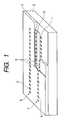
- Fig. 1 is a perspective view showing a cutout portion of the embodiment of the ink jet record head suitable for the present invention.
- the ink jet record head in the form shown in Fig. 1 has a structure wherein an isolation wall is extendedly placed from a discharge port 4 to the proximity of a supply chamber 6 for the sake of individually and independently forming a nozzle 5 which is a flow path of the ink to each of a plurality of heaters 1 which are the electrothermal converting elements.
- the ink jet record head has the plurality of heaters 2 and a plurality of nozzles 5, and is equipped with a first nozzle sequence 7 having the nozzles 5 in a longitudinal direction arranged in parallel and a second nozzle sequence 8 having the nozzles 5 in the longitudinal direction arranged in parallel at positions opposed to the first nozzle sequence 7 across the supply chamber 6.
- the first and second nozzle sequences 7 and 8 are formed to have adjacent nozzles at intervals of a 600 dpi pitch.
- the nozzles 5 in the second nozzle sequence 8 are arranged so that the pitches among the adjacent nozzles are mutually deviated by a 1/2 pitch against the nozzles 5 in the first nozzle sequence 7.
- the above-mentioned record head has an ink discharge means to which the ink jet recording system disclosed in Japanese Patent Application Laid-Open No. 4-10940 and Japanese Patent Application Laid-Open No. 4-10941 is applied, where bubbles generated when discharging the ink communicate with the outside air via the discharge port.
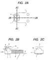
- Figs. 2A, 2B and 2C show the nozzle structure of the ink jet record head according to a first embodiment of the present invention.
- Fig. 2A is a plan perspective view for viewing one of the plurality of nozzles of the ink jet record head from a vertical direction to a substrate
- Fig. 2B is a sectional view along a line 2B-2B in Fig. 2A
- Fig. 2C is a sectional view along a line 2C-2C in Fig. 2A.
- the record head having the nozzle structure in this form is equipped with an element substrate 2 on which the plurality of heaters 1 which are the electrothermal converting elements are provided and a flow path composition substrate 3 stacked on and joined with a principal surface of the element substrate 2 to constitute a plurality of flow paths of the ink.
- the element substrate 2 is formed by glass, ceramics, resin, metal and so on for instance, and is generally formed by Si.
- the heater 1 an electrode (not shown) for applying a voltage to the heater 1, and wiring (not shown) connected to the electrode are provided in each flow path of the ink in a predetermined wiring pattern respectively.
- a insulation film (not shown) for improving emanation of thermal storage is provided as if to cover the heaters 1.
- a protective film (not shown) for protecting it from cavitation generated when the bubbles disappears is provided as if to cover the insulation film.
- the flow path composition substrate 3 has the plurality of nozzles 5 through which the ink flows, supply chamber 6 for supplying the ink to each of the nozzles 5 and the plurality of discharge ports 4 which are end openings of the nozzles 5 for discharging the ink droplets.
- the discharge ports 4 are formed at positions opposed to the heaters 1 on the element substrate 2.
- the nozzle 5 has a first discharge port portion including the discharge port 4, a second discharge port portion 10 for reducing flow resistance, a bubbling chamber 11 and a supply path 9 (shaded area in the drawing).
- the bubbling chamber 11 has a bottom face opposed to an opening face of the discharge port 4 approximately forming a rectangle formed on the heater 1.
- the supply path 9 has one end thereof communicating with the bubbling chamber 11 and the other end thereof communicating with the supply chamber 6, where a width of the supply path 9 is straightly formed to be almost equal from the supply chamber 6 to the bubbling chamber 11.
- the second discharge port portion 10 is successively formed on the bubbling chamber 11. Furthermore, the nozzles 5 is formed by orthogonalizing a discharge direction in which the ink droplets fly from the discharge port 4 and a flow direction of the ink liquid flowing in the supply path 9.
- the nozzle 5 shown in Fig. 1 is comprised of the first discharge port portion including the discharge port 4, second discharge port portion 10, bubbling chamber 11 and supply path 9, and has inner wall surfaces opposed to the principal surface of the element substrate 2 formed from the supply chamber 6 to the bubbling chamber 11 in parallel with the principal surface of the element substrate 2 respectively.
- the second discharge port portion 10 has a form in which angles on the upper side of a square are curved respectively on any cross section vertical to the principal surface of the above described element substrate and going through the center of the discharge port 4 and these curves are shaped as arcs of circles of a radius R inscribed in the angles on the upper side of the above described square.
- a lower side opposed to the upper side of the above described square is on the bubbling chamber 11 side.
- a height L in the vertical direction to the principal surface of the above described element substrate of the second discharge port portion 10 is smaller than a length I from a perpendicular line drawn down from the center of the discharge port 4 to the above described element substrate to an outermost circumference of the second discharge port portion 10 in the direction parallel with the principal surface of the above described element substrate.
- the second discharge port portion 10 is a symmetric figure congruent with the perpendicular line drawn down from the center of the discharge port 4 to the principal surface of the above described element substrate.
- the ink supplied to the inside of the supply chamber 6 is supplied to the nozzles 5 of the first nozzle sequence 7 and second nozzle sequence 8 respectively.
- the ink supplied to each nozzle 5 flows along the supply path 9 so as to be filled in the bubbling chamber 11.
- the ink filled in the bubbling chamber 11 is caused to fly by a growth pressure of the bubbles generated due to film boiling by the heater 1 in the direction almost orthogonal to the principal surface of the element substrate 2 so that it is discharged as the ink droplets from the discharge port 4.
- the ink filled in the bubbling chamber 11 is discharged, a part of it flows to the supply path 9 side due to the pressure of the bubbles generated in the bubbling chamber 11.
- the pressure of the bubbles generated in the bubbling chamber 11 is immediately conveyed to the second discharge port portion 10, and the ink filled in the bubbling chamber 11 and second discharge port portion 10 moves inside the second discharge port portion 10.
- the cross section parallel with the principal surface of the element substrate 2, that is, space volume of the second discharge port portion 10 is larger, and so a pressure loss rarely occurs and the ink is well discharged toward the discharge port 4.
- the discharge port at the end of the nozzle becomes smaller and the flow resistance in the discharge port direction becomes higher in the first discharge port portion, to curb reduction in the flow rate in the discharge port direction on discharging so as to prevent reduction in discharge speed of the ink droplets.
- the first embodiment is also effective on discharge volume fluctuation due to temperature rise in the head.
- the first embodiment in Fig. 2 has the advantage that, compared to the form of the second discharge port portion in the past (shown by a dashed line in Fig. 2B), the first discharge port portion and second discharge port portion have less stagnant areas of fluid in an uneven portion and less discharge volume fluctuation due to temperature rise.
- the record head in the past has a problem that thin areas increase in the thickness between the surface of a flow path composition member on which the discharge port is open and a ceiling surface of the second discharge port portion and so strength in the direction vertical to the principal surface of the element substrate is weak around the discharge port of the flow path composition member.
- the first embodiment also has the advantage that, as the ceiling surface of the second discharge port portion 10 is in a curved shape, the thickness up to the upper part of the discharge port is kept relatively thick and so the strength increases.
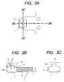
- Figs. 3A, 3B and 3C show the nozzle structure of the ink jet record head according to a second embodiment of the present invention.
- Fig. 3A is a plan perspective view for viewing one of the plurality of nozzles of the ink jet record head from the vertical direction to the substrate
- Fig. 3B is a sectional view along a line 3B-3B in Fig. 3A
- Fig. 3C is a sectional view along a line 3C-3C in Fig. 3A.
- the second discharge port portion 10 of the nozzle has the form in which the angles on the upper side of the square are curved respectively on any cross section vertical to the principal surface of the element substrate (surface on which the heaters 1 are formed) and going through the center of the discharge port 4, and these curves are shaped as arcs of a circle of a radius R having its center on the perpendicular line drawn down from the center of the discharge port 4 to the principal surface of the above described element substrate and going through an intersection point of the perpendicular line and the above described square and the right and left lower ends opened to the bubbling chamber 11 of the second discharge port portion 10.
- the lower side opposed to the upper side of the above described square is on the bubbling chamber 11 side.
- the height L in the vertical direction to the principal surface of the above described element substrate of the second discharge port portion 10 is smaller than the length l from the perpendicular line drawn down from the center of the discharge port 4 to the above described element substrate to the outermost circumference of the second discharge port portion 10 in the direction parallel with the principal surface of the above described element substrate.
- the second discharge port portion 10 is a symmetric figure congruent with the perpendicular line drawn down from the center of the discharge port 4 to the principal surface of the above described element substrate.
- the ink supplied to the inside of the supply chamber 6 is supplied to the nozzles 5 of the first nozzle sequence 7 and second nozzle sequence 8 respectively.
- the ink supplied to each nozzle 5 flows along the supply path 9 so as to be filled in the bubbling chamber 11.
- the ink filled in the bubbling chamber 11 is caused to fly by the growth pressure of the bubbles generated due to film boiling by the heater 1 in the direction almost orthogonal to the principal surface of the element substrate 2 so that it is discharged as the ink droplets from the discharge port 4.
- the ink filled in the bubbling chamber 11 is discharged, a part of it flows to the supply path 9 side due to the pressure of the bubbles generated in the bubbling chamber 11.
- the pressure of the bubbles generated in the bubbling chamber 11 is immediately conveyed to the second discharge port portion 10, and the ink filled in the bubbling chamber 11 and second discharge port portion 10 moves inside the second discharge port portion 10.
- the cross section parallel with the principal surface of the element substrate 2, that is, the space volume of the second discharge port portion 10 is larger, and so the pressure loss rarely occurs and the ink is well discharged toward the discharge port 4.
- the discharge port at the end of the nozzle becomes smaller and the flow resistance in the discharge port direction becomes higher in the first discharge port portion, to curb the reduction in the flow rate in the discharge port direction on discharging so as to prevent the reduction in the discharge speed of the ink droplets.
- the second embodiment is also effective on the discharge volume fluctuation due to the temperature rise in the head.
- the second embodiment in Fig. 3 has less stagnant areas of the fluid in the uneven portion in the first discharge port portion and second discharge port portion which are also smaller than the first embodiment, and is more effective in reducing the discharge volume fluctuation due to the temperature rise compared to the first embodiment.
- the record head in the past has the problem that the thin areas increase in the thickness between the surface of the flow path composition member on which the discharge port is open and the ceiling surface of the second discharge port portion and so the strength in the direction vertical to the principal surface of the element substrate is weak around the discharge port of the flow path composition member.
- the second embodiment also has the advantage that, as the ceiling surface of the second discharge port portion 10 is in the curved shape, the thickness up to the upper part of the discharge port is kept relatively thick and so the strength increases.
- Figs. 4A, 4B and 4C show the nozzle structure of the ink jet record head according to a third embodiment of the present invention.
- Fig. 4A is a plan perspective view for viewing one of the plurality of nozzles of the ink jet record head from the vertical direction to the substrate
- Fig. 4B is a sectional view along a line 4B-4B in Fig. 4A
- Fig. 4C is a sectional view along a line 4C-4C in Fig. 4A.
- the second discharge port portion 10 of the nozzle has the form in which the angles on the upper side of the square are curved respectively on any cross section vertical to the principal surface of the element substrate (surface on which the heaters 1 are formed) and going through the center of the discharge port 4, and these curves are shaped as arcs of a circle of a radius R inscribed in the angles on the upper side of the square respectively.
- the lower side opposed to the upper side of the above described square is on the bubbling chamber 11 side.
- the height L in the vertical direction to the principal surface of the above described element substrate of the second discharge port portion 10 is larger than the length l from the perpendicular line drawn down from the center of the discharge port 4 to the above described element substrate to the outermost circumference of the second discharge port portion 10 in the direction parallel with the principal surface of the above described element substrate.
- a lower layer of the second discharge port portion 10 is in a rectangular shape. This embodiment is an effective shape when forward resistance in the discharge port direction is reduced, that is, when the height of a resistance alleviation portion 10 is rendered higher.
- the second discharge port portion 10 is the symmetric figure congruent with the perpendicular line drawn down from the center of the discharge port 4 to the principal surface of the above described element substrate.
- the ink supplied to the inside of the supply chamber 6 is supplied to the nozzles 5 of the first nozzle sequence 7 and second nozzle sequence 8 respectively.
- the ink supplied to each nozzle 5 flows along the supply path 9 so as to be filled in the bubbling chamber 11.
- the ink filled in the bubbling chamber 11 is caused to fly by the growth pressure of the bubbles generated due to the film boiling by the heater 1 in the direction almost orthogonal to the principal surface of the element substrate 2 so that it is discharged as the ink droplets from the discharge port 4.
- the ink filled in the bubbling chamber 11 is discharged, a part of it flows to the supply path 9 side due to the pressure of the bubbles generated in the bubbling chamber 11.
- the pressure of the bubbles generated in the bubbling chamber 11 is immediately conveyed to the second discharge port portion 10, and the ink filled in the bubbling chamber 11 and second discharge port portion 10 moves inside the second discharge port portion 10.
- the cross section parallel with the principal surface of the element substrate 2, that is, the space volume of the second discharge port portion 10 is larger, and so the pressure loss rarely occurs and the ink is well discharged toward the discharge port 4.
- the discharge port at the end of the nozzle becomes smaller and the flow resistance in the discharge port direction becomes higher in the first discharge port portion, to curb the reduction in the flow rate in the discharge port direction on discharging so as to prevent the reduction in the discharge speed of the ink droplets.
- the third embodiment is also effective on the discharge volume fluctuation due to the temperature rise in the head.
- the third embodiment in Fig. 4 has the advantage that there are less stagnant areas of the fluid in the uneven portion between the first discharge port portion and second discharge port portion.
- the record head in the past has the problem that the thin areas increase in the thickness between the surface of the flow path composition member on which the discharge port is open and the ceiling surface of the second discharge port portion and so the strength in the direction vertical to the principal surface of the element substrate is weak around the discharge port of the flow path composition member.
- the third embodiment also has the advantage that, as the ceiling surface of the second discharge port portion 10 is in the curved shape, the thickness up to the upper part of the discharge port is kept relatively thick and so the strength increases.
- Figs. 5A, 5B and 5C show the nozzle structure of the ink jet record head according to a fourth embodiment of the present invention.
- Fig. 5A is a plan perspective view for viewing one of the plurality of nozzles of the ink jet record head from the vertical direction to the substrate
- Fig. 5B is a sectional view along a line 5B-5B in Fig. 5A
- Fig. 5C is a sectional view along a line 5C-5C in Fig. 5A.
- the second discharge port portion 10 of the nozzle has the form in which the angles on the upper side of the square are curved respectively on any cross section vertical to the principal surface of the element substrate (surface on which the heaters 1 are formed) and going through the center of the discharge port 4, and these curves are shaped as the arcs of the same circle of a radius R having its center on the perpendicular line drawn down from the center of the discharge port 4 to the principal surface of the above described element substrate and inscribed in the angles on the upper side of the square.
- the lower side opposed to the upper side of the above described square is on the bubbling chamber 11 side.
- the height L in the vertical direction to the principal surface of the above described element substrate of the second discharge port portion 10 is larger than the length l from the perpendicular line drawn down from the center of the discharge port 4 to the above described element substrate to the outermost circumference of the second discharge port portion 10 in the direction parallel with the principal surface of the above described element substrate.
- the lower layer of the second discharge port portion 10 is in the rectangular shape. This embodiment is the effective shape when the forward resistance in the discharge port direction is reduced, that is, when the height of the resistance alleviation portion 10 is rendered higher.
- the second discharge port portion 10 is the symmetric figure congruent with the perpendicular line drawn down from the center of the discharge port 4 to the principal surface of the above described element substrate.
- the ink supplied to the inside of the supply chamber 6 is supplied to the nozzles 5 of the first nozzle sequence 7 and second nozzle sequence 8 respectively.
- the ink supplied to each nozzle 5 flows along the supply path 9 so as to be filled in the bubbling chamber 11.
- the ink filled in the bubbling chamber 11 is caused to fly by the growth pressure of the bubbles generated due to the film boiling by the heater 1 in the direction almost orthogonal to the principal surface of the element substrate 2 so that it is discharged as the ink droplets from the discharge port 4.
- the ink filled in the bubbling chamber 11 is discharged, a part of it flows to the supply path 9 side due to the pressure of the bubbles generated in the bubbling chamber 11.
- the pressure of the bubbles generated in the bubbling chamber 11 is immediately conveyed to the second discharge port portion 10, and the ink filled in the bubbling chamber 11 and second discharge port portion 10 moves inside the second discharge port portion 10.
- the cross section parallel with the principal surface of the element substrate 2, that is, the space volume of the second discharge port portion 10 is larger, and so the pressure loss rarely occurs and the ink is well discharged toward the discharge port 4.
- the discharge port at the end of the nozzle becomes smaller and the flow resistance in the discharge port direction becomes higher in the first discharge port portion, to curb the reduction in the flow rate in the discharge port direction on discharging so as to prevent the reduction in the discharge speed of the ink droplets.
- the fourth embodiment is also effective on the discharge volume fluctuation due to the temperature rise in the head.
- the fourth embodiment in Fig. 5 has less stagnant areas of the fluid in the uneven portion between the first discharge port portion and second discharge port portion which are also smaller compared to the first and third embodiments, and is more effective at reducing the discharge volume fluctuation due to the temperature rise than the first and third embodiments.
- the record head in the past has the problem that the thin areas increase in the thickness between the surface of the flow path composition member on which the discharge port is open and the ceiling surface of the second discharge port portion and so the strength in the direction vertical to the principal surface of the element substrate is weak around the discharge port of the flow path composition member.
- the fourth embodiment also has the advantage that, as the ceiling surface of the second discharge port portion 10 is in the curved shape, the thickness up to the upper part of the discharge port is kept relatively thick and so the strength increases.
- the cross section parallel with the principal surface of the element substrate that is, the space volume of the second discharge port portion is larger compared to the record head in the past which does not have the second discharge port portion in the nozzle, and so the pressure loss rarely occurs and the ink is well discharged toward the discharge port.
- the discharge port at the end of the nozzle becomes smaller and the flow resistance in the discharge port direction becomes higher in the first discharge port portion, to curb the reduction in the flow rate in the discharge port direction on discharging so as to prevent the reduction in the discharge speed of the ink droplets.
- the ink flow close to the wall surface of the above-mentioned second discharge port portion becomes curved along the curb portion and has the flow speed for almost vertically colliding with the mainstream of the refill in the vertical direction to the above described element substrate. Therefore, the speed of rushing into the first discharge port portion of the refill mainstream in the vertical direction to the above described element substrate is reduced and the meniscus vibrations are consequently attenuated so that it can be safely discharged.
- the uneven portion between the first and second discharge port portions is smaller. Therefore, in the case where the discharge is successively performed at a high frequency, the minute stagnant areas of the ink having almost no flow speed become smaller in the flow in the discharge port direction after the bubbling. Consequently, the thermal storage of the ink is held down on successive discharge operations by the electrothermal converting element so that there will be fewer variations in the volume of discharged liquid droplets.
- the second discharge port portion is curved so that the thickness between the surface of the flow path composition member on which the discharge port is open and the ceiling surface of the second discharge port portion is kept relatively thick so as to increase the strength in the vertical direction on the principal surface of the element substrate around the discharge port on the flow path composition member.
Abstract
Description
Claims (5)
- An ink jet record head comprising:wherein said discharge port portion has:a plurality of nozzles through which liquid flows;a supply chamber for supplying the liquid to each of the nozzles; anda plurality of discharge ports which are nozzle end openings for discharging a liquid droplet, wherein said nozzle has:a flow path composition substrate comprised of a bubbling chamber in which a bubble is generated by a discharge energy generating element for generating thermal energy for discharging the liquid droplet, discharge port portions including said discharge ports and communicating between said discharge ports and said bubbling chamber and a supply path for supplying the ink to the bubbling chamber; andan element substrate on which said discharge energy generating element is provided and joining said flow path composition substrate with the principal surface, anda first discharge port portion of an almost fixed diameter including said discharge port; anda second discharge port portion contiguous to the first discharge port portion and communicating in steps with said first discharge port portion and said bubbling chamber respectively, anda boundary portion between said second discharge port portion and said bubbling chamber and the boundary portion between said second discharge port portion and said first discharge port portion are continuously formed by a wall having a curvature.
- The ink jet record head according to claim 1, wherein said second discharge port portion has a wall vertical to the principal surface of said element substrate and contiguous to the wall having said curvature in the boundary portion between said second discharge port portion and said bubbling chamber.
- The ink jet record head according to any one of claims 1 to 5, wherein said nozzles are formed by orthogonalizing a discharge direction in which liquid droplets fly from the discharge port and a flow direction of the liquid flowing in said supply path.
- The ink jet record head according to claim 1, wherein said flow path composition substrate has a plurality of said discharge energy generating elements and a plurality of said nozzles, and is equipped with a first nozzle sequence having the nozzles in a longitudinal direction arranged in parallel and a second nozzle sequence having the nozzles in the longitudinal direction arranged in parallel at positions opposed to the first nozzle sequence across said supply chamber respectively while the nozzles in the second nozzle sequence are arranged so that the pitches among the adjacent nozzles are mutually deviated by a 1/2 pitch against the nozzles in the first nozzle sequence.
- The ink jet record head according to any one of claims 1 to 4, wherein the bubbles generated by said discharge energy generating element communicate with the outside air by passing through said discharge port.
Applications Claiming Priority (4)
| Application Number | Priority Date | Filing Date | Title |
|---|---|---|---|
| JP2002201877 | 2002-07-10 | ||
| JP2002201877 | 2002-07-10 | ||
| JP2003271625 | 2003-07-07 | ||
| JP2003271625A JP4027281B2 (en) | 2002-07-10 | 2003-07-07 | Inkjet recording head |
Publications (3)
| Publication Number | Publication Date |
|---|---|
| EP1380420A2 true EP1380420A2 (en) | 2004-01-14 |
| EP1380420A3 EP1380420A3 (en) | 2004-06-16 |
| EP1380420B1 EP1380420B1 (en) | 2008-11-19 |
Family
ID=29738473
Family Applications (1)
| Application Number | Title | Priority Date | Filing Date |
|---|---|---|---|
| EP03015755A Expired - Lifetime EP1380420B1 (en) | 2002-07-10 | 2003-07-10 | Ink jet record head |
Country Status (7)
| Country | Link |
|---|---|
| US (2) | US6984026B2 (en) |
| EP (1) | EP1380420B1 (en) |
| JP (1) | JP4027281B2 (en) |
| KR (1) | KR100553623B1 (en) |
| CN (1) | CN1265964C (en) |
| DE (1) | DE60324737D1 (en) |
| TW (1) | TWI270466B (en) |
Families Citing this family (16)
| Publication number | Priority date | Publication date | Assignee | Title |
|---|---|---|---|---|
| DE10227255B4 (en) * | 2002-06-19 | 2008-06-26 | Hyperstone Gmbh | Method for recovering management records of a block-erasable memory |
| JP3891561B2 (en) | 2002-07-24 | 2007-03-14 | キヤノン株式会社 | Inkjet recording head |
| JP4323947B2 (en) | 2003-01-10 | 2009-09-02 | キヤノン株式会社 | Inkjet recording head |
| TWI306812B (en) * | 2005-10-17 | 2009-03-01 | Canon Kk | Liquid discharge head and manufacturing method of the same |
| CN101875261B (en) * | 2005-11-29 | 2012-05-23 | 佳能株式会社 | Liquid discharge method |
| JP2009056628A (en) | 2007-08-30 | 2009-03-19 | Canon Inc | Liquid ejection head and inkjet recording device |
| JP5058719B2 (en) * | 2007-08-30 | 2012-10-24 | キヤノン株式会社 | Liquid discharge head and ink jet recording apparatus |
| US7735962B2 (en) | 2007-08-31 | 2010-06-15 | Canon Kabushiki Kaisha | Ink jet print head |
| JP2009061672A (en) | 2007-09-06 | 2009-03-26 | Canon Inc | Ink-jet recording head |
| JP5393082B2 (en) * | 2008-08-29 | 2014-01-22 | キヤノン株式会社 | Liquid discharge head |
| JP5578859B2 (en) * | 2010-01-14 | 2014-08-27 | キヤノン株式会社 | Liquid discharge head and method of manufacturing liquid discharge head |
| JP6029308B2 (en) | 2011-04-19 | 2016-11-24 | キヤノン株式会社 | Method for driving liquid discharge head and liquid discharge apparatus |
| JP5770537B2 (en) * | 2011-06-02 | 2015-08-26 | 矢崎総業株式会社 | Insert molding die and collar insert molding method |
| JP6376731B2 (en) * | 2012-08-10 | 2018-08-22 | キヤノン株式会社 | Liquid discharge head and liquid discharge apparatus |
| JP5659202B2 (en) * | 2012-08-30 | 2015-01-28 | 京セラドキュメントソリューションズ株式会社 | Inkjet recording device |
| US10300698B2 (en) | 2017-06-05 | 2019-05-28 | Canon Kabushiki Kaisha | Liquid ejection head |
Citations (5)
| Publication number | Priority date | Publication date | Assignee | Title |
|---|---|---|---|---|
| JPS54161935A (en) | 1978-06-12 | 1979-12-22 | Seiko Epson Corp | Ink jet printer |
| JPS61185455A (en) | 1985-02-14 | 1986-08-19 | Olympus Optical Co Ltd | Ink jet printer |
| JPS61249768A (en) | 1985-04-30 | 1986-11-06 | Olympus Optical Co Ltd | Ink jet recording apparatus |
| JPH0410940A (en) | 1990-04-27 | 1992-01-16 | Canon Inc | Liquid jet method and recorder equipped with same method |
| JPH0410941A (en) | 1990-04-27 | 1992-01-16 | Canon Inc | Droplet jet method and recorder equipped with same method |
Family Cites Families (25)
| Publication number | Priority date | Publication date | Assignee | Title |
|---|---|---|---|---|
| DE2728657A1 (en) * | 1977-06-24 | 1979-01-04 | Siemens Ag | NOZZLE PLATE FOR INK WRITING DEVICES |
| JPS57107848A (en) | 1980-12-26 | 1982-07-05 | Ricoh Co Ltd | Ink jet nozzle plate |
| IN157880B (en) | 1982-10-27 | 1986-07-12 | Dunlop Ltd | |
| JP2671300B2 (en) | 1986-03-17 | 1997-10-29 | セイコーエプソン株式会社 | Ink jet recording device |
| JPH0412859A (en) * | 1990-04-28 | 1992-01-17 | Canon Inc | Liquid jetting method, recording head using the method and recording apparatus using the method |
| JPH05177834A (en) * | 1991-06-04 | 1993-07-20 | Seiko Epson Corp | Ink jet recording head |
| JPH06286129A (en) * | 1992-02-20 | 1994-10-11 | Seikosha Co Ltd | Ink jet head |
| US6137510A (en) * | 1996-11-15 | 2000-10-24 | Canon Kabushiki Kaisha | Ink jet head |
| JP3768645B2 (en) * | 1997-06-18 | 2006-04-19 | キヤノン株式会社 | Inkjet recording head |
| JPH1178029A (en) * | 1997-09-04 | 1999-03-23 | Canon Inc | Ink-jet recording head |
| US6540335B2 (en) * | 1997-12-05 | 2003-04-01 | Canon Kabushiki Kaisha | Ink jet print head and ink jet printing device mounting this head |
| US6350016B1 (en) * | 1998-02-10 | 2002-02-26 | Canon Kabushiki Kaisha | Liquid ejecting method and liquid ejecting head |
| JP3675272B2 (en) * | 1999-01-29 | 2005-07-27 | キヤノン株式会社 | Liquid discharge head and method for manufacturing the same |
| US6443561B1 (en) * | 1999-08-24 | 2002-09-03 | Canon Kabushiki Kaisha | Liquid discharge head, driving method therefor, and cartridge, and image forming apparatus |
| DE60041746D1 (en) * | 1999-10-12 | 2009-04-23 | Canon Kk | Ink jet printing apparatus and ink jet printing method |
| US6547381B2 (en) | 2000-06-23 | 2003-04-15 | Canon Kabushiki Kaisha | Ink, image recording process, ink cartridge, recording unit, ink set, crust-preventing method and image forming apparatus |
| US6398348B1 (en) * | 2000-09-05 | 2002-06-04 | Hewlett-Packard Company | Printing structure with insulator layer |
| US6830309B2 (en) * | 2000-09-06 | 2004-12-14 | Canon Kabushiki Kaisha | Method for manufacturing ink jet recording head, ink jet recording head and ink jet recording method |
| US6848769B2 (en) * | 2001-06-20 | 2005-02-01 | Canon Kabushiki Kaisha | Liquid ejecting head having a plurality of groups of ejection openings, and image-forming device using the same |
| CA2400881C (en) * | 2001-08-31 | 2006-12-19 | Canon Kabushiki Kaisha | Liquid ejection head and image-forming apparatus using the same |
| US6854820B2 (en) * | 2001-09-26 | 2005-02-15 | Canon Kabushiki Kaisha | Method for ejecting liquid, liquid ejection head and image-forming apparatus using the same |
| JP3927854B2 (en) * | 2002-04-23 | 2007-06-13 | キヤノン株式会社 | Inkjet recording head |
| JP2003311966A (en) * | 2002-04-23 | 2003-11-06 | Canon Inc | Ink jet recording head |
| JP4027282B2 (en) * | 2002-07-10 | 2007-12-26 | キヤノン株式会社 | Inkjet recording head |
| JP3891561B2 (en) * | 2002-07-24 | 2007-03-14 | キヤノン株式会社 | Inkjet recording head |
-
2003
- 2003-07-07 JP JP2003271625A patent/JP4027281B2/en not_active Expired - Fee Related
- 2003-07-08 US US10/614,009 patent/US6984026B2/en not_active Expired - Fee Related
- 2003-07-09 KR KR1020030046337A patent/KR100553623B1/en not_active IP Right Cessation
- 2003-07-10 DE DE60324737T patent/DE60324737D1/en not_active Expired - Lifetime
- 2003-07-10 CN CNB031467822A patent/CN1265964C/en not_active Expired - Fee Related
- 2003-07-10 EP EP03015755A patent/EP1380420B1/en not_active Expired - Lifetime
- 2003-07-10 TW TW092118900A patent/TWI270466B/en not_active IP Right Cessation
-
2005
- 2005-06-01 US US11/140,997 patent/US7090334B2/en not_active Expired - Fee Related
Patent Citations (5)
| Publication number | Priority date | Publication date | Assignee | Title |
|---|---|---|---|---|
| JPS54161935A (en) | 1978-06-12 | 1979-12-22 | Seiko Epson Corp | Ink jet printer |
| JPS61185455A (en) | 1985-02-14 | 1986-08-19 | Olympus Optical Co Ltd | Ink jet printer |
| JPS61249768A (en) | 1985-04-30 | 1986-11-06 | Olympus Optical Co Ltd | Ink jet recording apparatus |
| JPH0410940A (en) | 1990-04-27 | 1992-01-16 | Canon Inc | Liquid jet method and recorder equipped with same method |
| JPH0410941A (en) | 1990-04-27 | 1992-01-16 | Canon Inc | Droplet jet method and recorder equipped with same method |
Also Published As
| Publication number | Publication date |
|---|---|
| US20040056927A1 (en) | 2004-03-25 |
| CN1265964C (en) | 2006-07-26 |
| TWI270466B (en) | 2007-01-11 |
| DE60324737D1 (en) | 2009-01-02 |
| JP4027281B2 (en) | 2007-12-26 |
| US6984026B2 (en) | 2006-01-10 |
| JP2004042651A (en) | 2004-02-12 |
| CN1475349A (en) | 2004-02-18 |
| EP1380420B1 (en) | 2008-11-19 |
| TW200415027A (en) | 2004-08-16 |
| EP1380420A3 (en) | 2004-06-16 |
| US20050219326A1 (en) | 2005-10-06 |
| US7090334B2 (en) | 2006-08-15 |
| KR20040005680A (en) | 2004-01-16 |
| KR100553623B1 (en) | 2006-02-22 |
Similar Documents
| Publication | Publication Date | Title |
|---|---|---|
| US7090334B2 (en) | Ink jet record head | |
| EP1380419B1 (en) | Ink jet record head | |
| US4897674A (en) | Liquid jet recording head | |
| US5119116A (en) | Thermal ink jet channel with non-wetting walls and a step structure | |
| JP4323947B2 (en) | Inkjet recording head | |
| US7530661B2 (en) | Substrate and method of forming substrate for fluid ejection device | |
| CN103534098B (en) | Fluid ejection apparatus | |
| EP0464733B1 (en) | Thermal ink jet printhead with location control of bubble collapse | |
| EP0876916B1 (en) | Ink jet recording head | |
| US6554403B1 (en) | Substrate for fluid ejection device | |
| JP4137164B2 (en) | Inkjet recording head | |
| EP1216835B1 (en) | Ink-jet printhead | |
| AU736931B2 (en) | Liquid discharging head and liquid discharging device | |
| JP3045858B2 (en) | Liquid jet head | |
| US6773092B1 (en) | Liquid discharging head and liquid discharging device | |
| JP3466804B2 (en) | INK JET HEAD AND INK JET RECORDING APPARATUS HAVING THE SAME | |
| JP2664220B2 (en) | Liquid jet recording head | |
| JP2005125696A (en) | Inkjet recording head | |
| JPH04118247A (en) | Ink jet recording device | |
| JPH1178021A (en) | Ink jet recording head and ink jet recorder | |
| JPH0911461A (en) | Ink-jet recording head |
Legal Events
| Date | Code | Title | Description |
|---|---|---|---|
| PUAI | Public reference made under article 153(3) epc to a published international application that has entered the european phase |
Free format text: ORIGINAL CODE: 0009012 |
|
| AK | Designated contracting states |
Kind code of ref document: A2 Designated state(s): AT BE BG CH CY CZ DE DK EE ES FI FR GB GR HU IE IT LI LU MC NL PT RO SE SI SK TR |
|
| AX | Request for extension of the european patent |
Extension state: AL LT LV MK |
|
| PUAL | Search report despatched |
Free format text: ORIGINAL CODE: 0009013 |
|
| AK | Designated contracting states |
Kind code of ref document: A3 Designated state(s): AT BE BG CH CY CZ DE DK EE ES FI FR GB GR HU IE IT LI LU MC NL PT RO SE SI SK TR |
|
| AX | Request for extension of the european patent |
Extension state: AL LT LV MK |
|
| 17P | Request for examination filed |
Effective date: 20041216 |
|
| AKX | Designation fees paid |
Designated state(s): DE FR GB IT |
|
| 17Q | First examination report despatched |
Effective date: 20060331 |
|
| GRAP | Despatch of communication of intention to grant a patent |
Free format text: ORIGINAL CODE: EPIDOSNIGR1 |
|
| GRAS | Grant fee paid |
Free format text: ORIGINAL CODE: EPIDOSNIGR3 |
|
| GRAA | (expected) grant |
Free format text: ORIGINAL CODE: 0009210 |
|
| AK | Designated contracting states |
Kind code of ref document: B1 Designated state(s): DE FR GB IT |
|
| REG | Reference to a national code |
Ref country code: GB Ref legal event code: FG4D |
|
| REF | Corresponds to: |
Ref document number: 60324737 Country of ref document: DE Date of ref document: 20090102 Kind code of ref document: P |
|
| PLBE | No opposition filed within time limit |
Free format text: ORIGINAL CODE: 0009261 |
|
| STAA | Information on the status of an ep patent application or granted ep patent |
Free format text: STATUS: NO OPPOSITION FILED WITHIN TIME LIMIT |
|
| 26N | No opposition filed |
Effective date: 20090820 |
|
| REG | Reference to a national code |
Ref country code: FR Ref legal event code: PLFP Year of fee payment: 14 |
|
| PGFP | Annual fee paid to national office [announced via postgrant information from national office to epo] |
Ref country code: DE Payment date: 20160731 Year of fee payment: 14 Ref country code: GB Payment date: 20160727 Year of fee payment: 14 Ref country code: IT Payment date: 20160704 Year of fee payment: 14 |
|
| PGFP | Annual fee paid to national office [announced via postgrant information from national office to epo] |
Ref country code: FR Payment date: 20160726 Year of fee payment: 14 |
|
| REG | Reference to a national code |
Ref country code: DE Ref legal event code: R119 Ref document number: 60324737 Country of ref document: DE |
|
| GBPC | Gb: european patent ceased through non-payment of renewal fee |
Effective date: 20170710 |
|
| REG | Reference to a national code |
Ref country code: FR Ref legal event code: ST Effective date: 20180330 |
|
| PG25 | Lapsed in a contracting state [announced via postgrant information from national office to epo] |
Ref country code: DE Free format text: LAPSE BECAUSE OF NON-PAYMENT OF DUE FEES Effective date: 20180201 Ref country code: GB Free format text: LAPSE BECAUSE OF NON-PAYMENT OF DUE FEES Effective date: 20170710 |
|
| PG25 | Lapsed in a contracting state [announced via postgrant information from national office to epo] |
Ref country code: FR Free format text: LAPSE BECAUSE OF NON-PAYMENT OF DUE FEES Effective date: 20170731 |
|
| PG25 | Lapsed in a contracting state [announced via postgrant information from national office to epo] |
Ref country code: IT Free format text: LAPSE BECAUSE OF NON-PAYMENT OF DUE FEES Effective date: 20170710 |