EP1380145B1 - Method and device for transmitting and receiving digital data - Google Patents
Method and device for transmitting and receiving digital data Download PDFInfo
- Publication number
- EP1380145B1 EP1380145B1 EP02761967A EP02761967A EP1380145B1 EP 1380145 B1 EP1380145 B1 EP 1380145B1 EP 02761967 A EP02761967 A EP 02761967A EP 02761967 A EP02761967 A EP 02761967A EP 1380145 B1 EP1380145 B1 EP 1380145B1
- Authority
- EP
- European Patent Office
- Prior art keywords
- data
- digital data
- stream
- buffer
- receiving
- Prior art date
- Legal status (The legal status is an assumption and is not a legal conclusion. Google has not performed a legal analysis and makes no representation as to the accuracy of the status listed.)
- Expired - Lifetime
Links
- 238000000034 method Methods 0.000 title claims abstract description 51
- 230000005540 biological transmission Effects 0.000 claims abstract description 13
- 238000013500 data storage Methods 0.000 claims description 8
- 238000004590 computer program Methods 0.000 claims description 5
- 238000012790 confirmation Methods 0.000 claims description 3
- 238000012545 processing Methods 0.000 claims description 2
- 230000000295 complement effect Effects 0.000 description 3
- 238000004364 calculation method Methods 0.000 description 2
- 230000001934 delay Effects 0.000 description 2
- 238000012546 transfer Methods 0.000 description 2
- RYGMFSIKBFXOCR-UHFFFAOYSA-N Copper Chemical compound [Cu] RYGMFSIKBFXOCR-UHFFFAOYSA-N 0.000 description 1
- 239000000969 carrier Substances 0.000 description 1
- 238000004891 communication Methods 0.000 description 1
- 239000010949 copper Substances 0.000 description 1
- 229910052802 copper Inorganic materials 0.000 description 1
- 230000005611 electricity Effects 0.000 description 1
- 230000006870 function Effects 0.000 description 1
- 239000003365 glass fiber Substances 0.000 description 1
Images


Classifications
-
- H—ELECTRICITY
- H04—ELECTRIC COMMUNICATION TECHNIQUE
- H04L—TRANSMISSION OF DIGITAL INFORMATION, e.g. TELEGRAPHIC COMMUNICATION
- H04L25/00—Baseband systems
- H04L25/02—Details ; arrangements for supplying electrical power along data transmission lines
- H04L25/14—Channel dividing arrangements, i.e. in which a single bit stream is divided between several baseband channels and reassembled at the receiver
-
- H—ELECTRICITY
- H04—ELECTRIC COMMUNICATION TECHNIQUE
- H04L—TRANSMISSION OF DIGITAL INFORMATION, e.g. TELEGRAPHIC COMMUNICATION
- H04L5/00—Arrangements affording multiple use of the transmission path
-
- H—ELECTRICITY
- H04—ELECTRIC COMMUNICATION TECHNIQUE
- H04L—TRANSMISSION OF DIGITAL INFORMATION, e.g. TELEGRAPHIC COMMUNICATION
- H04L1/00—Arrangements for detecting or preventing errors in the information received
- H04L1/02—Arrangements for detecting or preventing errors in the information received by diversity reception
Definitions
- the invention relates to a method for transmitting digital data according to the preamble of claim 1, and software for that purpose.
- the data are sent via a medium in the form of data packets. This can take place via a physical cabling in for instance copper or glass fibre, or via infrared or radio waves.
- the invention provides a method according to claim 1. Additionally the invention provides a method for transmitting digital data, wherein a packet of digital data is simultaneously sent from the beginning of the packet towards the end and from the end towards the beginning. Additionally the invention provides a method for transmitting digital data, wherein simultaneously a packet of digital data is sent and the same packet is sent backwards.
- the invention relates to sending this data via electromagnetic waves, eg electronically or optically.
- Another advantage of the method is that no other control signals or techniques are necessary to reconstruct the entire signal or data packet or to adjust both streams to each other: the signal or data packet is complete when the two streams meet each other, or when the data buffer is full. Delays in one of either lines do not lead to loss of signal.
- the transmission capacity is smaller than the receiving capacity.
- the transmission capacity is smaller than the receiving capacity.
- the one data stream can for example enter via a telephone line and the second data stream via a cable, the electricity grit or cordless via GSM. It is also possible to let the data streams enter via one cable by means of physical multiplexing.
- the invention therefore actually offers a specific form of digital multiplexing.
- the present invention relates to a method as described, wherein a first device sends the data from front to rear to a third device, and a second device sends the same data from rear to front to the third device.
- a first device sends the data from front to rear to a third device
- a second device sends the same data from rear to front to the third device.
- the third device is able to have all data available very quickly.
- the third device places the data in a data buffer the size of the packet, and sends a signal to the first and second device when either the buffer is full, or stops sending confirmations until the buffer is full. In this way the coordination between both streams is very simple.
- a first device sends data from front to rear to a second device, and simultaneously backwards to a third device.
- the possibility is offered to very quickly provide two devices with all data, with an optimally used bandwidth.
- the second device and third device immediately at receipt forward the data they received from the first device to each other. As a result both devices can optimally use their bandwidth and transmission capacity.
- the second and third devices have each been provided with a data buffer the size of the packet, wherein the received data are placed in the data buffer and the second and third devices send a signal to the first device when the respective data buffer is full.
- the invention relates to a method for sending a data packet to a first device in an organic (also called 'ad-hoc') data network of devices, wherein the devices have been provided with a data processing unit, a data buffer and software having receiving routines for receiving data packets from at least two transmitting devices in the data network, wherein at least two other devices in the network simultaneously send complementary data packets to the first device which added together form the data packet.
- organic also called 'ad-hoc'
- said software has further been provided with transmission routines for transmitting data packets, received from the transmitting device or devices in the data network to at least one receiving device that is connected to the data network, independent of the transmitting device or devices.
- the invention relates to a method for receiving digital data, wherein a device provided with data storage means creates a data buffer in the data storage means the size of a packet of digital data, and simultaneously receives a first stream of digital data and receives a second stream of digital data, wherein the device fills the data buffer from front to rear with the first stream of digital data and fills the data buffer from rear to front with the second stream of digital data.
- the device informs the source or sources of the streams of digital data when a data buffer is full.
- the coordination is simple.
- the invention relates to a method for sending digital data, wherein a device provided with data storage means creates a data buffer in the data storage means, stores digital data in the data buffer, and from the front of the data buffer and the rear of the data buffer sends the digital data in two streams.
- the device stops sending after receipt of a signal.
- the coordination is again simple.
- the invention relates to software provided with routines for carrying out the method according to one of methods mentioned above.
- routines are necessary to that end, and how said routines have to function with respect to each other.
- Such software may of course be immediately implemented in hardware, for instance in a PROM, EPROM or the like.
- the invention relates to software for sending a packet of digital data, comprising a first transmission routine for sending a first stream of digital data starting from the front of the packet of digital data and a second transmission routine for sending a second stream of digital data starting from the end of the packet of digital data
- the invention relates to software for receiving a packet of digital data, comprising a first receiving routine for receiving a first stream of digital data and a second recieving routine for simultaneously receiving a second stream of digital data, and a first storing routine for storing the first stream of digital data in a memory starting at the front of the memory and filling the memory towards the end, and a second storing routine for storing the second stream of digital data starting at the end of the memory and filling the memory towards the front, and a stop routine for ending the receiving of digital data when the memory is full.
- the invention relates to an apparatus for sending a packet of digital data, comprising memory means for storing the packet of digital data, first sending means for sending a first stream of digital data, starting at the front of the memory means and second sending means for sending a second stream of digital data, starting at the end of the memory means.
- the invention relates to an apparatus for receiving a packet of digital data, comprising memory means for storing the packet of digital data, first receiving means for receiving a first stream of digital data, and storing it in said memory means, starting from the front of the memory means, and second receiving means for receiving a second stream of digital data, and storing it in said memory means, starting from the back of the memory means.
- the invention relates to a carrier provided with software as described, and to a device provided with software as described.
- packets of digital data are sent in the form of bitstreams.
- the packets are divided into smaller sub-packets, for instance numbered 1..n.
- the sub-packets are sent 1, 2, etc in the first stream, i.e. sequentially, starting with the first sub-packet, and the sub-packets are sent n, n-1, ... etc in the second stream, i.e. sequentially, starting with the last sub-packet.
- these two streams are sent almost simultaneous.
- the two streams can be sent over the same carrier, for instance using conventional multiplexing techniques, or they can be sent over entirely different carriers, for instance cable modem and telephone line.
- the digital data can also be of another form instead of the now-used binairy data.
- Figure 1 shows a situation in which a signal 5 in a conventional manner enters a receiver 3.
- the receiver 3 splits the signal, or each data packet from which the signal has been built up, into two streams 1 and 2 to forward it to receiver 4.
- Stream 1 is the signal sent from the front, that means the first bit of the data packet or the signal is sent first, then the second, etc.
- Stream 2 is the signal 5 or a data packet thereof, but then backwards, that means first the last bit is sent then the last but one, etc.
- the two streams may be considered as complementary streams.
- Receiver 4 simultaneously fills its data buffer from the front with signal 1 and from the rear with signal 2. This can take place by means of a computer program, but can also be implemented hardware-wise. When the buffer is full, that means the complete signal or data packet has been received, receiver 4 sends a signal to receiver/transmitter 3 that the buffer is full, that means that the signal has been received. It is of course also possible that the receiver 4 keeps sending a signal to receiver/transmitter 3 until the buffer is full, or just closes down the connection when the buffer is full, or sets the port at high or low.
- the principle depicted in figure 1, can also be used in figure 2 with 2 sources 3, 3' that transmit to a receiver 4.
- the sources 3, 3' receive the entire (or already split) signal or data packet 5, and each send a partial signal 1 or 2, respectively, to receiver 4.
- This offers advantages when the transmission capacity of sources 3 and 3' is lower than the receiving capacity of receiver 4.
- the receiver 4 may even forward the reconstructed signal or data packet 6 in its entirety again.
- Figure 3 shows an example of the method according to the present invention, wherein one source 3 splits a signal or data packet 5 into two complementary streams 1 and 2.
- the one stream is sent to receiver 4, the other stream to receiver 4'.
- Both receivers 4 and 4' send what is received to each other, so that both obtain a complete signal or data packet again.
- This offers advantages when the transmission capacity/bandwidth of 3 is limited, but/and the capacity between 4 and 4' is sufficient for exchange of data.
- Figure 4 shows an example wherein a source 3 splits a signal or data packet 5 into two streams, wherein stream 1 is sent to receivers 4, 4", and stream 2 to receiver 4'. Receiver 4' forwards its part of the signal or data packet to 4 and 4", whereas 4 forwards its part to 4'. In the optimal case all receivers 4, 4' and 4" will receive the entire signal or data packet in less time than usually needed in conventional point-to-point connections, or while using less bandwidth.
- Figure 5 shows an example of the use of the method according to the invention, wherein a source 3 having limited data transfer capacity splits a signal or data packet 5 into two streams 1 and 2.
- Stream 1 is sent to receiver 4, stream 2 to receiver 4", and receivers 4 and 4" forward their part to receiver 4'.
- receivers 4 and 4" forward their part to receiver 4'.
- three receivers have received the entire signal or data packet within less time usually needed to send the packet in its entirety to all three receivers, and the bandwidth used is smaller.
- Figures 6 and 7 show calculation examples wherein in case of figure 6 the available bandwidth from transmitter 3 to receivers 4 and 4' is almost the same. In that case receivers 4 and 4' will have received the data in 50% of the usually necessary time, and this is also the load for transmitter 3, seen in bandwidth, only 2 times 50% in total instead of 2 times 100%. Thus, digital data is sent without any overhead (transmitter 3 may stop sending when all data is sent) and very fast.
- connection is a-synchronous.
- Receiver 4' receives 91% of the total data packet, and receiver 4 receives 11% of the total data packet.
- transmitter 3 in the end only needs to send the total data packet once. Additionally there will be a small gain of speed in this unfavourable case.
- the sending capacity from transmitter 3 to receiver 4 as well as the sending capacity from receiver 4 to receiver 4'. Due to very lowtransmission capacity from receiver 4 to receiver 4' (or delays) only 9 % instead of 11 % could be transmitted from receiver 4 to receiver 4'.
- FIG 8A-8C the process of receiving a digital data packet split into two streams accoding to the present invention is shown.
- two streams 21 and 22 are received and put into data buffer 20.
- the first part of the received data from stream 21 is put in place 1
- the first part of received data from stream 22 is put in place n.
- I figure 8B an intermediate step is shown.
- the 4th data part is received and is put into buffer at location 4, while via stream 22 also another (n-i th) data part is recieved.
- the two streams meet, the buffer is full. This will trigger the device to stop receiving, or send a signal that the digital data packet is complete.
- FIGS 9A-9C the sending side is shown.
- data buffer 23 is full of data.
- the device starts taking data from data buffer, starting at the front of the data buffer 23, and starts sending the data.
- the device starts taking data from the back of databuffer 23, position n, and sends this data.
- FIG 9B taken some time later, it can be seen that the device takes data part 3 from data buffer 23 and sends it.
- the fifth data part is teken and send.
- the device sequentially takes the next, etc, so the next data parts would be number 4 and the 6th from the back.
- figure 9C the last data parts are taken. Again, it can be seen that sending is swift, and without complex overhead.
- Figures 10A-10D show the situation where there is a device which both sends and receives according to the present invention.
- data buffer 26 is empty,
- the devive starts receiving data parts via streams 28 and 29, stream 28 is put at the first place, and stream 28 will subsequently fill data buffer 26 from the front to the back.
- the first data part received from stream 29 will be put into the last position, n, of the data buffer 26.
- stream 29 will fill data buffer 26 from the back to the front, until the buffer is full.
- the device starts sending data parts via streams 30 and 31.
- Stream 30 starts from the front of the data buffer and stream 31 starts from the back of the data buffer.
- the device receives data parts faster than it sends them.
- all the data parts are received: the two streams 28 and 29 meet.
- the device keeps sending via streams 30 and 31.
- the streams 30 and 31 meet, and the device can stop sending. This is all possible with a minimum on overhead.
- Apparatus 40 having data buffer 42 sends two streams of data 44 and 45.
- Apparatus 41 receives these two streams as streams 46 and 47, and puts the data in data buffer 43.
- the sending apparatus 40 has two streams 44 and 45, one starting at the front and one at the back of data buffer 42.
- Receiving apparatus 41 receives two streams, and places one stream in the front, and one in the back of data buffer 43.
- the method according to the invention can for instance be used in GSM or other cordless telephony.
- a conversation or a data stream can then be divided into packets which, in accordance with the method according to the invention, can be sent.
- Use can then also be made of the available bandwidth: each data stream can be sent over another band, so that optimal use is made of the available bandwidth.
Abstract
Description
- The invention relates to a method for transmitting digital data according to the preamble of
claim 1, and software for that purpose. - In practice very many methods to send data are known, particularly through a network. An example are digital data that are sent through the internet, but also digital telephone signals, such as for instance in case of cordless GSM telephones.
- In practice there are also various methods known for transmitting digital data.
- The data are sent via a medium in the form of data packets. This can take place via a physical cabling in for instance copper or glass fibre, or via infrared or radio waves.
- Because the capacity, often coupled to bandwidth, of the media over which the data are being sent mostly is too small, the data are often compressed. However, this has often appeared not to be sufficient.
- Additionally many of these methods are aimed at optimising the data transfer between two computers.
- In Maxemchuk: "Dispersity routing" International conference on communication of June 16-18, 1975, a method is described for sending a message along more than one path.
- It is among others an object of the present invention to at least partially solve these problems. To that end the invention provides a method according to
claim 1. Additionally the invention provides a method for transmitting digital data, wherein a packet of digital data is simultaneously sent from the beginning of the packet towards the end and from the end towards the beginning. Additionally the invention provides a method for transmitting digital data, wherein simultaneously a packet of digital data is sent and the same packet is sent backwards. - By splitting the data stream in two simultaneous streams, wherein the one stream starts sending the data from the front and works its way to the rear, and the other stream works its way from the rear to the front, the possibility is given to very quickly send data between and to for instance computers. In most of the cases, the invention relates to sending this data via electromagnetic waves, eg electronically or optically.
- Another advantage of the method is that no other control signals or techniques are necessary to reconstruct the entire signal or data packet or to adjust both streams to each other: the signal or data packet is complete when the two streams meet each other, or when the data buffer is full. Delays in one of either lines do not lead to loss of signal.
- In many cases the data connection is a-symmetrical: the transmission capacity is smaller than the receiving capacity. In the method according to the invention it is possible, despite the smaller transmission capacity, to nonetheless use the full receiving capacity. This may for instance be of importance in so-called streaming broadcasts through the internet, wherein through the internet digital radio broadcasts and in future even television or video can take place. Both data streams can also enter via various lines.
- For instance the one data stream can for example enter via a telephone line and the second data stream via a cable, the electricity grit or cordless via GSM. It is also possible to let the data streams enter via one cable by means of physical multiplexing. The invention therefore actually offers a specific form of digital multiplexing.
- Preferably the present invention relates to a method as described, wherein a first device sends the data from front to rear to a third device, and a second device sends the same data from rear to front to the third device. As a result the third device is able to have all data available very quickly.
- Preferably the third device places the data in a data buffer the size of the packet, and sends a signal to the first and second device when either the buffer is full, or stops sending confirmations until the buffer is full. In this way the coordination between both streams is very simple.
- It is preferred that in a method according to the invention a first device sends data from front to rear to a second device, and simultaneously backwards to a third device. As a result the possibility is offered to very quickly provide two devices with all data, with an optimally used bandwidth. In this method it is preferred that the second device and third device immediately at receipt forward the data they received from the first device to each other. As a result both devices can optimally use their bandwidth and transmission capacity.
- In said method it is preferred that the second and third devices have each been provided with a data buffer the size of the packet, wherein the received data are placed in the data buffer and the second and third devices send a signal to the first device when the respective data buffer is full.
- Additionally the invention relates to a method for sending a data packet to a first device in an organic (also called 'ad-hoc') data network of devices, wherein the devices have been provided with a data processing unit, a data buffer and software having receiving routines for receiving data packets from at least two transmitting devices in the data network, wherein at least two other devices in the network simultaneously send complementary data packets to the first device which added together form the data packet.
- Preferably said software has further been provided with transmission routines for transmitting data packets, received from the transmitting device or devices in the data network to at least one receiving device that is connected to the data network, independent of the transmitting device or devices.
- Additionally the invention relates to a method for receiving digital data, wherein a device provided with data storage means creates a data buffer in the data storage means the size of a packet of digital data, and simultaneously receives a first stream of digital data and receives a second stream of digital data, wherein the device fills the data buffer from front to rear with the first stream of digital data and fills the data buffer from rear to front with the second stream of digital data.
- Preferably the device informs the source or sources of the streams of digital data when a data buffer is full. As a result the coordination is simple.
- Additionally the invention relates to a method for sending digital data, wherein a device provided with data storage means creates a data buffer in the data storage means, stores digital data in the data buffer, and from the front of the data buffer and the rear of the data buffer sends the digital data in two streams.
- Preferably the device stops sending after receipt of a signal. As a result the coordination is again simple.
- Additionally the invention relates to software provided with routines for carrying out the method according to one of methods mentioned above.
- From the above description, in combination with the figures and their description, it will immediately be clear to an expert which routines are necessary to that end, and how said routines have to function with respect to each other. Such software may of course be immediately implemented in hardware, for instance in a PROM, EPROM or the like.
- Additionally, the invention relates to software for sending a packet of digital data, comprising a first transmission routine for sending a first stream of digital data starting from the front of the packet of digital data and a second transmission routine for sending a second stream of digital data starting from the end of the packet of digital data
- Furthermore, the invention relates to software for receiving a packet of digital data, comprising a first receiving routine for receiving a first stream of digital data and a second recieving routine for simultaneously receiving a second stream of digital data, and a first storing routine for storing the first stream of digital data in a memory starting at the front of the memory and filling the memory towards the end, and a second storing routine for storing the second stream of digital data starting at the end of the memory and filling the memory towards the front, and a stop routine for ending the receiving of digital data when the memory is full.
- Furthermore, the invention relates to an apparatus for sending a packet of digital data, comprising memory means for storing the packet of digital data, first sending means for sending a first stream of digital data, starting at the front of the memory means and second sending means for sending a second stream of digital data, starting at the end of the memory means.
- Furthermore, the invention relates to an apparatus for receiving a packet of digital data, comprising memory means for storing the packet of digital data, first receiving means for receiving a first stream of digital data, and storing it in said memory means, starting from the front of the memory means, and second receiving means for receiving a second stream of digital data, and storing it in said memory means, starting from the back of the memory means.
- Additionally the invention relates to a carrier provided with software as described, and to a device provided with software as described.
- In a specific embodiment of the invention, packets of digital data are sent in the form of bitstreams. In another embodiment, the packets are divided into smaller sub-packets, for instance numbered 1..n. In this case, the sub-packets are sent 1, 2, etc in the first stream, i.e. sequentially, starting with the first sub-packet, and the sub-packets are sent n, n-1, ... etc in the second stream, i.e. sequentially, starting with the last sub-packet. In a further embodiment, these two streams are sent almost simultaneous. The two streams can be sent over the same carrier, for instance using conventional multiplexing techniques, or they can be sent over entirely different carriers, for instance cable modem and telephone line. The digital data can also be of another form instead of the now-used binairy data.
- The invention is further elucidated on the basis of the figures that are exemplary embodiments of the invention. However, the invention is not limited to said exemplary embodiments. Shown in the figures is:
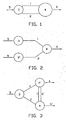
- Figure 1 the splitting of one signal into two signals and the adding together at the receiver;
- Figure 2 the receipt of a split signal by a receiver from two physically separated sources,
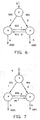
- Figure 3 the provision of two receivers with one signal,
- Figure 4 the provision of three receivers with one signal,
- Figure 5 an alternative for the situation of figure 4,
- Figure 6 an example of the relation between bandwidth and the quantity of signal,
- Figure 7 a second example of the relation between bandwidth and quantity of signal,
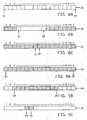
- Figure 8A-8C a receiving device,
- Figure 9A-9C a sending device,
- Figure 10A-10D a device which receives and almost simultaneously sends, and
- Figure 11 the process of sending and receiving.
- Figure 1 shows a situation in which a
signal 5 in a conventional manner enters areceiver 3. Thereceiver 3 splits the signal, or each data packet from which the signal has been built up, into twostreams receiver 4.Stream 1 is the signal sent from the front, that means the first bit of the data packet or the signal is sent first, then the second, etc.Stream 2 is thesignal 5 or a data packet thereof, but then backwards, that means first the last bit is sent then the last but one, etc. - Therefore, as both streams make up the entire stream, the two streams may be considered as complementary streams.
-
Receiver 4 simultaneously fills its data buffer from the front withsignal 1 and from the rear withsignal 2. This can take place by means of a computer program, but can also be implemented hardware-wise. When the buffer is full, that means the complete signal or data packet has been received,receiver 4 sends a signal to receiver/transmitter 3 that the buffer is full, that means that the signal has been received. It is of course also possible that thereceiver 4 keeps sending a signal to receiver/transmitter 3 until the buffer is full, or just closes down the connection when the buffer is full, or sets the port at high or low. - The principle depicted in figure 1, can also be used in figure 2 with 2
sources 3, 3' that transmit to areceiver 4. In that case thesources 3, 3' receive the entire (or already split) signal ordata packet 5, and each send apartial signal receiver 4. This offers advantages when the transmission capacity ofsources 3 and 3' is lower than the receiving capacity ofreceiver 4. Thereceiver 4 may even forward the reconstructed signal ordata packet 6 in its entirety again. - Figure 3 shows an example of the method according to the present invention, wherein one
source 3 splits a signal ordata packet 5 into twocomplementary streams receiver 4, the other stream to receiver 4'. Bothreceivers 4 and 4' send what is received to each other, so that both obtain a complete signal or data packet again. This offers advantages when the transmission capacity/bandwidth of 3 is limited, but/and the capacity between 4 and 4' is sufficient for exchange of data. - Figure 4 shows an example wherein a
source 3 splits a signal ordata packet 5 into two streams, whereinstream 1 is sent toreceivers stream 2 to receiver 4'. Receiver 4' forwards its part of the signal or data packet to 4 and 4", whereas 4 forwards its part to 4'. In the optimal case allreceivers - Figure 5 shows an example of the use of the method according to the invention, wherein a
source 3 having limited data transfer capacity splits a signal ordata packet 5 into twostreams Stream 1 is sent toreceiver 4,stream 2 toreceiver 4", andreceivers - Figures 6 and 7 show calculation examples wherein in case of figure 6 the available bandwidth from
transmitter 3 toreceivers 4 and 4' is almost the same. In thatcase receivers 4 and 4' will have received the data in 50% of the usually necessary time, and this is also the load fortransmitter 3, seen in bandwidth, only 2times 50% in total instead of 2times 100%. Thus, digital data is sent without any overhead (transmitter 3 may stop sending when all data is sent) and very fast. - In the calculation example of figure 7 the connection is a-synchronous. Receiver 4' receives 91% of the total data packet, and
receiver 4 receives 11% of the total data packet. The net result is thattransmitter 3 in the end only needs to send the total data packet once. Additionally there will be a small gain of speed in this unfavourable case. In this case, the sending capacity fromtransmitter 3 toreceiver 4, as well as the sending capacity fromreceiver 4 to receiver 4'. Due to very lowtransmission capacity fromreceiver 4 to receiver 4' (or delays) only 9 % instead of 11 % could be transmitted fromreceiver 4 to receiver 4'. - In figure 8A-8C, the process of receiving a digital data packet split into two streams accoding to the present invention is shown. In figure 8A, two
streams data buffer 20. The first part of the received data fromstream 21 is put inplace 1, the first part of received data fromstream 22 is put in place n. I figure 8B, an intermediate step is shown. In this case, viastream 21 the 4th data part is received and is put into buffer atlocation 4, while viastream 22 also another (n-i th) data part is recieved. Despite the fact that the two streams are not equally fast, no overhead is needed.. In figure 8C, the two streams meet, the buffer is full. This will trigger the device to stop receiving, or send a signal that the digital data packet is complete. - In figures 9A-9C, the sending side is shown. In figure 9A,
data buffer 23 is full of data. The device starts taking data from data buffer, starting at the front of thedata buffer 23, and starts sending the data. At the same time, the device starts taking data from the back ofdatabuffer 23, position n, and sends this data. In figure 9B, taken some time later, it can be seen that the device takesdata part 3 fromdata buffer 23 and sends it. At the same time, from the rear end of the data buffer the fifth data part is teken and send. The device sequentially takes the next, etc, so the next data parts would benumber 4 and the 6th from the back. In figure 9C, the last data parts are taken. Again, it can be seen that sending is swift, and without complex overhead. - Figures 10A-10D show the situation where there is a device which both sends and receives according to the present invention. This time,
data buffer 26 is empty, The devive starts receiving data parts viastreams stream 28 is put at the first place, andstream 28 will subsequently filldata buffer 26 from the front to the back. The first data part received fromstream 29 will be put into the last position, n, of thedata buffer 26. Subsequently,stream 29 will fill data buffer 26 from the back to the front, until the buffer is full. - At the same time, the device starts sending data parts via
streams Stream 30 starts from the front of the data buffer and stream 31 starts from the back of the data buffer. - In figure 10C, it can be seen that in this case, the device receives data parts faster than it sends them. In figure 10C, all the data parts are received: the two
streams streams streams - In figure 11, The process of sending and receiving are depicted in one figure.
Apparatus 40 having data buffer 42 sends two streams ofdata Apparatus 41 receives these two streams asstreams data buffer 43. Again, the sendingapparatus 40 has twostreams data buffer 42. Receivingapparatus 41 receives two streams, and places one stream in the front, and one in the back ofdata buffer 43. - For that matter the method according to the invention can for instance be used in GSM or other cordless telephony. A conversation or a data stream can then be divided into packets which, in accordance with the method according to the invention, can be sent. Use can then also be made of the available bandwidth: each data stream can be sent over another band, so that optimal use is made of the available bandwidth.
Claims (17)
- A method for transmitting or receiving a sequence of n items of digital data, characterised in that said items of digital data are transmitted, respectively received, in the order from 1 to n and simultaneously in the order from n to 1.
- The method according to claim 1, wherein a first device transmits the data in the order from 1 to n to a third device, and a second device transmits the same data in the order from n to 1 to the third device.
- The method according to claim 2, wherein the sequence of items is a packet and the third device places the data in a data buffer the size of the packet, and sends a signal to the first and second devices when either the buffer is full, or stops sending confirmations until the buffer is full.
- The method according to claim 1, wherein a first device 3. The method according to claim 2, wherein the sequence of items is a packet and the third device places the data In a data buffer the size of the packet, and sends a signal to the first and second devices when either the buffer is full, or stops sending confirmations until the buffer is full. sends data from 1 to n to a second device, and simultaneously from n to 1 to a third device.
- The method according to claim 4, wherein the second device and third device forward the data they received from the first device to each other.
- The method according to claim 5, wherein the sequence of items is a packet and the second and third devices have each been provided with a data buffer the size of the packet, wherein the received data are placed in the data buffer and the second and third devices send a signal to the first device when the respective data buffer is full.
- A method for transmitting digital data to a first device in an ad-hoc data network of devices using the method of claim 1, characterised in that the devices have been provided with a data processing unit, a data buffer and software having receiving routines for receiving data from at least two transmitting devices in the data network, wherein at least two other devices in the network simultaneously transmit data together making up said digital data at least one device transmitting in the order from 1 to n, and at least one device with transmitting in the order n to 1, to said first device, which first device merges these data to form said digital data.
- The method according to claim 7, wherein the software has further been provided with transmission routines for transmitting data, received from the transmitting device or devices in the data network to at least one receiving device that is connected to the data network, independent of the transmitting device or devices.
- A method for receiving digital data according to claim 1, characterised in that a device provided with data storage means defines a data buffer in the data storage means, said data buffer having the size of n items of digital data, and simultaneously receives a first stream of digital data and a second stream of digital data, wherein the device fills the data buffer from 1 to n with the first stream of digital data and fills the data buffer from n to 1 with the second stream of digital data.
- The method according to claim 9, wherein the device notifies the source or sources of the streams of digital data when the data buffer is full.
- A method for sending digital data according to claim 1, characterised in that a device provided with data storage means defines a data buffer in the data storage means, stores digital data in the data buffer, and from the front of the data buffer and the rear of the data buffer sends the digital data in two streams.
- The method according to claim 11, wherein the device stops sending after receipt of a signal or when all the data in the data buffer has been sent.
- The method of claim 1, characterised in that said items transmitted in the order 1 to n and said items transmitted in the order n to 1 are transmitted via different transmission channels including different bands.
- Data carrier provided with computer program code adapted to perform the steps of the method of claim 1 when said code is run on a computer, characterised in that said computer program code comprises a first transmission routine for performing the step of transmitting a first stream of digital data in the order from 1 to n and a second transmission routine for performing the step of transmitting a second stream of digital data in the order from n to 1.
- Data carrier provided with computer program code adapted to perform the method of receiving according to claim 1, when said code is run on a computer, characterised in said computer program code comprises a first receiving routine for performing the step of receiving a first stream of digital data being transmitted in the order from 1 to n and a second receiving routine for performing the step of simultaneously receiving a second stream of digital data being transmitted in the order form n to 1, and a first storing routine for performing the step of storing the first stream of digital data in a memory, having positions 1 to n, starting at position 1 and filling the memory towards position n, and a second storing routine for performing the step of storing the second stream of digital data starting at position n and filling the memory towards position 1, and a stop routine for performing the step of ending the receiving of digital data when the memory is full.
- An apparatus for transmitting digital data using the method of claim 1, characterised in that said apparatus comprises memory means for storing the digital data, first sending means for sending a first stream of digital data in the order from 1 to n and second sending means for sending a second stream of digital data in the order from n to 1.
- An apparatus for receiving digital data, transmitted using the method of claim 1, characterised in that said apparatus comprises:- memory means for storing the n items of digital data, having positions 1 to n;- first receiving means for receiving a first stream of digital data being transmitted in the order 1 to n and storing it in said memory means, starting on position 1 of the memory means, and- second receiving means for receiving a second stream of digital data being transmitted in the order n to 1 and storing it in said memory means, starting on position n of the memory means.
Applications Claiming Priority (3)
| Application Number | Priority Date | Filing Date | Title |
|---|---|---|---|
| NL1017870A NL1017870C2 (en) | 2001-04-18 | 2001-04-18 | Method for inverse multiplexing. |
| NL1017870 | 2001-04-18 | ||
| PCT/NL2002/000253 WO2002084933A2 (en) | 2001-04-18 | 2002-04-18 | Method for inverse multiplexing |
Publications (2)
| Publication Number | Publication Date |
|---|---|
| EP1380145A2 EP1380145A2 (en) | 2004-01-14 |
| EP1380145B1 true EP1380145B1 (en) | 2006-09-13 |
Family
ID=19773256
Family Applications (1)
| Application Number | Title | Priority Date | Filing Date |
|---|---|---|---|
| EP02761967A Expired - Lifetime EP1380145B1 (en) | 2001-04-18 | 2002-04-18 | Method and device for transmitting and receiving digital data |
Country Status (18)
| Country | Link |
|---|---|
| US (3) | US6687263B2 (en) |
| EP (1) | EP1380145B1 (en) |
| JP (2) | JP4591993B2 (en) |
| KR (1) | KR100631769B1 (en) |
| CN (1) | CN100589461C (en) |
| AT (1) | ATE339833T1 (en) |
| AU (1) | AU2002307631B2 (en) |
| BR (1) | BR0209049A (en) |
| CA (1) | CA2444344C (en) |
| DE (1) | DE60214691T2 (en) |
| DK (1) | DK1380145T3 (en) |
| EA (1) | EA005969B1 (en) |
| ES (1) | ES2274083T3 (en) |
| IL (2) | IL158438A0 (en) |
| MX (1) | MXPA03009534A (en) |
| NL (1) | NL1017870C2 (en) |
| PT (1) | PT1380145E (en) |
| WO (1) | WO2002084933A2 (en) |
Families Citing this family (22)
| Publication number | Priority date | Publication date | Assignee | Title |
|---|---|---|---|---|
| NL1017870C2 (en) | 2001-04-18 | 2002-10-25 | Marc Van Oldenborgh | Method for inverse multiplexing. |
| NL1018463C2 (en) | 2001-07-04 | 2003-01-08 | Marc Van Oldenborgh | Method, layout and software for digitally inverse multiplexing. |
| KR100460758B1 (en) * | 2001-12-31 | 2004-12-09 | 매그나칩 반도체 유한회사 | Method for packing and unpacking variable length code |
| US7690573B2 (en) * | 2006-07-27 | 2010-04-06 | Spx Corporation | Alternator and starter tester with bar code functionality and method |
| US7134324B2 (en) * | 2004-10-29 | 2006-11-14 | Spx Corporation | Alternator holding apparatus and method for alternator testing |
| US7336462B2 (en) * | 2004-10-29 | 2008-02-26 | Spx Corporation | Alternator and starter tester protection apparatus and method |
| US7212911B2 (en) * | 2004-10-29 | 2007-05-01 | Spx Corporation | Alternator and starter tester apparatus and method |
| US7300041B2 (en) * | 2004-10-29 | 2007-11-27 | Spx Corporation | Vertical alternator holding apparatus and method for alternator testing |
| US7150186B2 (en) * | 2004-10-29 | 2006-12-19 | Spx Corporation | Door interlock apparatus and method for alternator/starter bench testing device |
| US7152464B2 (en) * | 2004-10-29 | 2006-12-26 | Spx Corporation | Belt tensioning apparatus and method for alternator testing |
| US7134325B2 (en) * | 2004-10-29 | 2006-11-14 | Spx Corporation | Starter motor holding apparatus and method for starter motor testing |
| US7583178B2 (en) * | 2005-03-16 | 2009-09-01 | Datalogic Mobile, Inc. | System and method for RFID reader operation |
| US7498806B2 (en) * | 2005-06-20 | 2009-03-03 | Spx Corporation | Apparatus and method for isolating noise from a signal |
| KR101213155B1 (en) * | 2006-08-21 | 2012-12-17 | 삼성전자주식회사 | Method of controlling data transmission in a wireless relay system, and the relay system implementing the method |
| KR100829221B1 (en) | 2007-01-26 | 2008-05-14 | 삼성전자주식회사 | Method of controlling data transmission mode in an orthogonal frequency division multeplexing wireless relay system, and aparatus using the same |
| US8165292B2 (en) | 2008-10-14 | 2012-04-24 | Nagra France | Method and system for secure distribution of audiovisual data encapsulated according to a plurality of transport protocols |
| CA2788799A1 (en) * | 2010-02-05 | 2011-08-11 | Catch the Wind, Inc. | High-density wind velocity data collection for wind turbine |
| US10055711B2 (en) | 2012-02-22 | 2018-08-21 | Bosch Automotive Service Solutions Inc. | Alternator and starter tester with warranty code functionality and method |
| US9128156B2 (en) | 2012-05-03 | 2015-09-08 | Bosch Automotive Service Solutions Inc. | Alternator and starter tester with other failures determination functionality and method |
| US8903595B2 (en) | 2012-09-17 | 2014-12-02 | Bosch Automotive Service Solutions Llc | Alternator and starter tester with increased load and cable identification |
| US9797956B2 (en) | 2015-11-24 | 2017-10-24 | Bosch Automotive Service Solutions Inc. | System and method for testing alternator default mode operation |
| US10193413B2 (en) | 2015-12-15 | 2019-01-29 | Bosch Automotive Service Solutions Inc. | Mounting bracket for water cooled type alternator |
Family Cites Families (32)
| Publication number | Priority date | Publication date | Assignee | Title |
|---|---|---|---|---|
| GB2229832B (en) | 1989-03-30 | 1993-04-07 | Intel Corp | Byte swap instruction for memory format conversion within a microprocessor |
| JPH0342940A (en) | 1989-07-11 | 1991-02-25 | Mitsubishi Electric Corp | Atm switching device |
| JPH0575651A (en) * | 1991-09-13 | 1993-03-26 | Nec Corp | Packet transmission system |
| DE69326935T2 (en) | 1993-03-02 | 2000-05-18 | Ibm | Method and device for the transmission of a data stream with high bit repetition frequency via independent digital communication channels |
| US5799018A (en) * | 1994-05-19 | 1998-08-25 | Nippon Telegraph And Telephone Corp. | Method and system for private communication with efficient use of bus type transmission path |
| EP0982942B1 (en) * | 1994-07-29 | 2004-06-02 | Sharp Kabushiki Kaisha | Video storage type communication device |
| US5668923A (en) * | 1995-02-28 | 1997-09-16 | Motorola, Inc. | Voice messaging system and method making efficient use of orthogonal modulation components |
| AU5663296A (en) * | 1995-04-10 | 1996-10-30 | Corporate Computer Systems, Inc. | System for compression and decompression of audio signals fo r digital transmission |
| US5570356A (en) * | 1995-06-07 | 1996-10-29 | International Business Machines Corporation | High bandwidth communications system having multiple serial links |
| JPH0964913A (en) | 1995-08-24 | 1997-03-07 | Chokosoku Network Computer Gijutsu Kenkyusho:Kk | Data guarateeing method for packet communication |
| US6415398B1 (en) * | 1995-09-29 | 2002-07-02 | Kabushiki Kaisha Toshiba | Coding system and decoding system |
| US5819117A (en) | 1995-10-10 | 1998-10-06 | Microunity Systems Engineering, Inc. | Method and system for facilitating byte ordering interfacing of a computer system |
| GB2310106B (en) * | 1996-02-12 | 2000-07-05 | Northern Telecom Ltd | Communications in a distribution network |
| WO1998008355A1 (en) * | 1996-08-16 | 1998-02-26 | Northern Telecom Limited | Inverse multiplexing of digital data |
| US6665733B1 (en) | 1996-12-30 | 2003-12-16 | Hewlett-Packard Development Company, L.P. | Network communication device including bonded ports for increased bandwidth |
| US6198749B1 (en) | 1997-04-03 | 2001-03-06 | Nortel Networks Limited | System for inverse multiplexing analog channels |
| US6078565A (en) * | 1997-06-20 | 2000-06-20 | Digital Equipment Corporation | Method and apparatus to expand an on chip FIFO into local memory |
| US6160808A (en) | 1997-12-18 | 2000-12-12 | 3Com Corporation | Technique for transmitting incoming multi-link point-to-point (PPP) packet traffic over multiple outgoing links in a multi-link bundle |
| JPH11225161A (en) | 1998-02-05 | 1999-08-17 | Matsushita Electric Ind Co Ltd | Data processing method and its device |
| US6275503B1 (en) * | 1998-07-24 | 2001-08-14 | Honeywell International Inc. | Method for transmitting large information packets over networks |
| DE19841531B4 (en) | 1998-09-10 | 2011-07-28 | T-Mobile Deutschland GmbH, 53227 | Method for the optimized transmission of multimedia services in mobile communication networks (mobile radio networks) |
| IT1307016B1 (en) * | 1999-01-27 | 2001-10-11 | Cselt Centro Studi Lab Telecom | PROCEDURE AND DEVICE FOR THE TRANSMISSION OF NUMERICAL SIGNALS. |
| US6220267B1 (en) * | 1999-01-27 | 2001-04-24 | Ceramatec, Inc. | Apparatus and method for controllably delivering fluid to a second fluid stream |
| JP2000269999A (en) | 1999-03-19 | 2000-09-29 | Fujitsu Ltd | Inter-network communication system |
| JP4276698B2 (en) | 1999-04-20 | 2009-06-10 | 富士通株式会社 | Data communication system and recording medium |
| AU5369400A (en) | 1999-10-05 | 2001-04-12 | Alcatel | Traffic allocation on virtual trunks |
| US6775305B1 (en) * | 1999-10-21 | 2004-08-10 | Globespanvirata, Inc. | System and method for combining multiple physical layer transport links |
| US6876669B2 (en) * | 2001-01-08 | 2005-04-05 | Corrigent Systems Ltd. | Packet fragmentation with nested interruptions |
| US6707864B2 (en) * | 2001-01-25 | 2004-03-16 | Interdigital Technology Corporation | Simplified block linear equalizer with block space time transmit diversity |
| GB2399998B (en) * | 2001-02-01 | 2005-04-13 | Fujitsu Ltd | Communications systems |
| NL1017870C2 (en) | 2001-04-18 | 2002-10-25 | Marc Van Oldenborgh | Method for inverse multiplexing. |
| NL1018463C2 (en) | 2001-07-04 | 2003-01-08 | Marc Van Oldenborgh | Method, layout and software for digitally inverse multiplexing. |
-
2001
- 2001-04-18 NL NL1017870A patent/NL1017870C2/en not_active IP Right Cessation
-
2002
- 2002-04-08 US US10/119,103 patent/US6687263B2/en not_active Expired - Lifetime
- 2002-04-18 EA EA200301132A patent/EA005969B1/en not_active IP Right Cessation
- 2002-04-18 PT PT02761967T patent/PT1380145E/en unknown
- 2002-04-18 CN CN02810155A patent/CN100589461C/en not_active Expired - Fee Related
- 2002-04-18 BR BR0209049-0A patent/BR0209049A/en not_active IP Right Cessation
- 2002-04-18 EP EP02761967A patent/EP1380145B1/en not_active Expired - Lifetime
- 2002-04-18 IL IL15843802A patent/IL158438A0/en active IP Right Grant
- 2002-04-18 DK DK02761967T patent/DK1380145T3/en active
- 2002-04-18 CA CA002444344A patent/CA2444344C/en not_active Expired - Fee Related
- 2002-04-18 WO PCT/NL2002/000253 patent/WO2002084933A2/en active IP Right Grant
- 2002-04-18 AT AT02761967T patent/ATE339833T1/en active
- 2002-04-18 KR KR1020037013694A patent/KR100631769B1/en not_active IP Right Cessation
- 2002-04-18 MX MXPA03009534A patent/MXPA03009534A/en active IP Right Grant
- 2002-04-18 DE DE60214691T patent/DE60214691T2/en not_active Expired - Lifetime
- 2002-04-18 ES ES02761967T patent/ES2274083T3/en not_active Expired - Lifetime
- 2002-04-18 AU AU2002307631A patent/AU2002307631B2/en not_active Ceased
- 2002-04-18 JP JP2002582541A patent/JP4591993B2/en not_active Expired - Fee Related
-
2003
- 2003-10-16 IL IL158438A patent/IL158438A/en not_active IP Right Cessation
- 2003-12-08 US US10/730,837 patent/US7738513B2/en not_active Expired - Fee Related
-
2008
- 2008-08-21 JP JP2008212590A patent/JP4809405B2/en not_active Expired - Fee Related
-
2010
- 2010-05-07 US US12/775,746 patent/US7995624B2/en not_active Expired - Fee Related
Non-Patent Citations (1)
| Title |
|---|
| HARRY NEWTON: "Newton's Telecom Dictionary", 2000, TELECOM BOOKS, NEW YORK * |
Also Published As
Similar Documents
| Publication | Publication Date | Title |
|---|---|---|
| US7995624B2 (en) | Systems and methods for multiplexing digital data | |
| AU2002307631A1 (en) | Method for inverse multiplexing | |
| US4387271A (en) | Combined telephone and data-transfer system | |
| US7778554B2 (en) | System and method for transmitting data on return path of a cable television system | |
| MXPA03005691A (en) | Delivering video over an atm/dsl network using a multi-layered video coding system. | |
| CN1136872A (en) | Broadband communication system | |
| CH675333A5 (en) | ||
| EP0116627A1 (en) | Recorded program communication system | |
| JP2005501441A5 (en) | ||
| EP1407587B1 (en) | Dispersity coding for inverse multiplexing | |
| AU2002318050A1 (en) | Dispersity coding for inverse multiplexing | |
| CN1075039A (en) | Increase speech interleave with reducing time delay | |
| AU650969B2 (en) | Bidirectional data transmission | |
| AU654417B2 (en) | A process for transmitting communications signals | |
| KR20080013652A (en) | Method for transferring audio data without disconnection in a wireless audio system | |
| JP3408215B2 (en) | A cell interleaving method in an ATM (Asynchronous Transmission Mode) switching system. | |
| EP1274206A1 (en) | Buffering in hybrid packet-TDM gateway |
Legal Events
| Date | Code | Title | Description |
|---|---|---|---|
| PUAI | Public reference made under article 153(3) epc to a published international application that has entered the european phase |
Free format text: ORIGINAL CODE: 0009012 |
|
| 17P | Request for examination filed |
Effective date: 20031017 |
|
| AK | Designated contracting states |
Kind code of ref document: A2 Designated state(s): AT BE CH CY DE DK ES FI FR GB GR IE IT LI LU MC NL PT SE TR |
|
| AX | Request for extension of the european patent |
Extension state: AL LT LV MK RO SI |
|
| 17Q | First examination report despatched |
Effective date: 20040329 |
|
| RTI1 | Title (correction) |
Free format text: METHOD AND DEVICE FOR TRANSMITTING AND RECEIVING DIGITAL DATA |
|
| GRAP | Despatch of communication of intention to grant a patent |
Free format text: ORIGINAL CODE: EPIDOSNIGR1 |
|
| GRAS | Grant fee paid |
Free format text: ORIGINAL CODE: EPIDOSNIGR3 |
|
| GRAA | (expected) grant |
Free format text: ORIGINAL CODE: 0009210 |
|
| AK | Designated contracting states |
Kind code of ref document: B1 Designated state(s): AT BE CH CY DE DK ES FI FR GB GR IE IT LI LU MC NL PT SE TR |
|
| PG25 | Lapsed in a contracting state [announced via postgrant information from national office to epo] |
Ref country code: IT Free format text: LAPSE BECAUSE OF FAILURE TO SUBMIT A TRANSLATION OF THE DESCRIPTION OR TO PAY THE FEE WITHIN THE PRESCRIBED TIME-LIMIT;WARNING: LAPSES OF ITALIAN PATENTS WITH EFFECTIVE DATE BEFORE 2007 MAY HAVE OCCURRED AT ANY TIME BEFORE 2007. THE CORRECT EFFECTIVE DATE MAY BE DIFFERENT FROM THE ONE RECORDED. Effective date: 20060913 |
|
| REG | Reference to a national code |
Ref country code: GB Ref legal event code: FG4D |
|
| REG | Reference to a national code |
Ref country code: CH Ref legal event code: EP |
|
| REG | Reference to a national code |
Ref country code: IE Ref legal event code: FG4D |
|
| REF | Corresponds to: |
Ref document number: 60214691 Country of ref document: DE Date of ref document: 20061026 Kind code of ref document: P |
|
| REG | Reference to a national code |
Ref country code: SE Ref legal event code: TRGR |
|
| REG | Reference to a national code |
Ref country code: CH Ref legal event code: NV Representative=s name: BRAUNPAT BRAUN EDER AG |
|
| REG | Reference to a national code |
Ref country code: DK Ref legal event code: T3 |
|
| REG | Reference to a national code |
Ref country code: PT Ref legal event code: SC4A Free format text: AVAILABILITY OF NATIONAL TRANSLATION Effective date: 20061206 |
|
| ET | Fr: translation filed | ||
| REG | Reference to a national code |
Ref country code: ES Ref legal event code: FG2A Ref document number: 2274083 Country of ref document: ES Kind code of ref document: T3 |
|
| PLBE | No opposition filed within time limit |
Free format text: ORIGINAL CODE: 0009261 |
|
| STAA | Information on the status of an ep patent application or granted ep patent |
Free format text: STATUS: NO OPPOSITION FILED WITHIN TIME LIMIT |
|
| 26N | No opposition filed |
Effective date: 20070614 |
|
| PG25 | Lapsed in a contracting state [announced via postgrant information from national office to epo] |
Ref country code: GR Free format text: LAPSE BECAUSE OF FAILURE TO SUBMIT A TRANSLATION OF THE DESCRIPTION OR TO PAY THE FEE WITHIN THE PRESCRIBED TIME-LIMIT Effective date: 20061214 |
|
| PG25 | Lapsed in a contracting state [announced via postgrant information from national office to epo] |
Ref country code: MC Free format text: LAPSE BECAUSE OF NON-PAYMENT OF DUE FEES Effective date: 20070430 |
|
| PG25 | Lapsed in a contracting state [announced via postgrant information from national office to epo] |
Ref country code: CY Free format text: LAPSE BECAUSE OF FAILURE TO SUBMIT A TRANSLATION OF THE DESCRIPTION OR TO PAY THE FEE WITHIN THE PRESCRIBED TIME-LIMIT Effective date: 20060913 |
|
| PGFP | Annual fee paid to national office [announced via postgrant information from national office to epo] |
Ref country code: ES Payment date: 20120426 Year of fee payment: 11 |
|
| PGFP | Annual fee paid to national office [announced via postgrant information from national office to epo] |
Ref country code: AT Payment date: 20120403 Year of fee payment: 11 |
|
| PGFP | Annual fee paid to national office [announced via postgrant information from national office to epo] |
Ref country code: BE Payment date: 20130429 Year of fee payment: 12 Ref country code: CH Payment date: 20130429 Year of fee payment: 12 Ref country code: LU Payment date: 20130502 Year of fee payment: 12 Ref country code: DK Payment date: 20130429 Year of fee payment: 12 Ref country code: IE Payment date: 20130425 Year of fee payment: 12 |
|
| PGFP | Annual fee paid to national office [announced via postgrant information from national office to epo] |
Ref country code: PT Payment date: 20130408 Year of fee payment: 12 Ref country code: FI Payment date: 20130429 Year of fee payment: 12 Ref country code: IT Payment date: 20130422 Year of fee payment: 12 Ref country code: TR Payment date: 20130415 Year of fee payment: 12 |
|
| REG | Reference to a national code |
Ref country code: PT Ref legal event code: MM4A Free format text: LAPSE DUE TO NON-PAYMENT OF FEES Effective date: 20141020 |
|
| REG | Reference to a national code |
Ref country code: DK Ref legal event code: EBP Effective date: 20140430 |
|
| PG25 | Lapsed in a contracting state [announced via postgrant information from national office to epo] |
Ref country code: LU Free format text: LAPSE BECAUSE OF NON-PAYMENT OF DUE FEES Effective date: 20140418 |
|
| PGFP | Annual fee paid to national office [announced via postgrant information from national office to epo] |
Ref country code: SE Payment date: 20140929 Year of fee payment: 13 |
|
| REG | Reference to a national code |
Ref country code: CH Ref legal event code: PL |
|
| REG | Reference to a national code |
Ref country code: AT Ref legal event code: MM01 Ref document number: 339833 Country of ref document: AT Kind code of ref document: T Effective date: 20140418 |
|
| REG | Reference to a national code |
Ref country code: IE Ref legal event code: MM4A |
|
| PG25 | Lapsed in a contracting state [announced via postgrant information from national office to epo] |
Ref country code: PT Free format text: LAPSE BECAUSE OF NON-PAYMENT OF DUE FEES Effective date: 20141020 Ref country code: FI Free format text: LAPSE BECAUSE OF NON-PAYMENT OF DUE FEES Effective date: 20140418 Ref country code: LI Free format text: LAPSE BECAUSE OF NON-PAYMENT OF DUE FEES Effective date: 20140430 Ref country code: CH Free format text: LAPSE BECAUSE OF NON-PAYMENT OF DUE FEES Effective date: 20140430 |
|
| PG25 | Lapsed in a contracting state [announced via postgrant information from national office to epo] |
Ref country code: AT Free format text: LAPSE BECAUSE OF NON-PAYMENT OF DUE FEES Effective date: 20140418 |
|
| PGFP | Annual fee paid to national office [announced via postgrant information from national office to epo] |
Ref country code: NL Payment date: 20140926 Year of fee payment: 13 |
|
| PG25 | Lapsed in a contracting state [announced via postgrant information from national office to epo] |
Ref country code: IT Free format text: LAPSE BECAUSE OF NON-PAYMENT OF DUE FEES Effective date: 20140418 |
|
| REG | Reference to a national code |
Ref country code: FR Ref legal event code: PLFP Year of fee payment: 14 |
|
| PG25 | Lapsed in a contracting state [announced via postgrant information from national office to epo] |
Ref country code: DK Free format text: LAPSE BECAUSE OF NON-PAYMENT OF DUE FEES Effective date: 20140430 Ref country code: IE Free format text: LAPSE BECAUSE OF NON-PAYMENT OF DUE FEES Effective date: 20140418 |
|
| REG | Reference to a national code |
Ref country code: ES Ref legal event code: FD2A Effective date: 20150528 |
|
| PG25 | Lapsed in a contracting state [announced via postgrant information from national office to epo] |
Ref country code: ES Free format text: LAPSE BECAUSE OF NON-PAYMENT OF DUE FEES Effective date: 20140419 |
|
| REG | Reference to a national code |
Ref country code: SE Ref legal event code: EUG |
|
| REG | Reference to a national code |
Ref country code: NL Ref legal event code: MM Effective date: 20150501 |
|
| PG25 | Lapsed in a contracting state [announced via postgrant information from national office to epo] |
Ref country code: SE Free format text: LAPSE BECAUSE OF NON-PAYMENT OF DUE FEES Effective date: 20150419 |
|
| PG25 | Lapsed in a contracting state [announced via postgrant information from national office to epo] |
Ref country code: NL Free format text: LAPSE BECAUSE OF NON-PAYMENT OF DUE FEES Effective date: 20150501 |
|
| REG | Reference to a national code |
Ref country code: FR Ref legal event code: PLFP Year of fee payment: 15 |
|
| PGFP | Annual fee paid to national office [announced via postgrant information from national office to epo] |
Ref country code: FR Payment date: 20161031 Year of fee payment: 15 Ref country code: DE Payment date: 20161031 Year of fee payment: 15 |
|
| PG25 | Lapsed in a contracting state [announced via postgrant information from national office to epo] |
Ref country code: BE Free format text: LAPSE BECAUSE OF NON-PAYMENT OF DUE FEES Effective date: 20140430 |
|
| PG25 | Lapsed in a contracting state [announced via postgrant information from national office to epo] |
Ref country code: TR Free format text: LAPSE BECAUSE OF NON-PAYMENT OF DUE FEES Effective date: 20140418 |
|
| REG | Reference to a national code |
Ref country code: DE Ref legal event code: R119 Ref document number: 60214691 Country of ref document: DE |
|
| REG | Reference to a national code |
Ref country code: FR Ref legal event code: ST Effective date: 20171229 |
|
| PG25 | Lapsed in a contracting state [announced via postgrant information from national office to epo] |
Ref country code: FR Free format text: LAPSE BECAUSE OF NON-PAYMENT OF DUE FEES Effective date: 20170502 Ref country code: DE Free format text: LAPSE BECAUSE OF NON-PAYMENT OF DUE FEES Effective date: 20171103 |
|
| PGFP | Annual fee paid to national office [announced via postgrant information from national office to epo] |
Ref country code: GB Payment date: 20190520 Year of fee payment: 18 |
|
| GBPC | Gb: european patent ceased through non-payment of renewal fee |
Effective date: 20200418 |
|
| PG25 | Lapsed in a contracting state [announced via postgrant information from national office to epo] |
Ref country code: GB Free format text: LAPSE BECAUSE OF NON-PAYMENT OF DUE FEES Effective date: 20200418 |