EP1376154A1 - An Active Night Vision System for a Motor Vehicle - Google Patents
An Active Night Vision System for a Motor Vehicle Download PDFInfo
- Publication number
- EP1376154A1 EP1376154A1 EP03101603A EP03101603A EP1376154A1 EP 1376154 A1 EP1376154 A1 EP 1376154A1 EP 03101603 A EP03101603 A EP 03101603A EP 03101603 A EP03101603 A EP 03101603A EP 1376154 A1 EP1376154 A1 EP 1376154A1
- Authority
- EP
- European Patent Office
- Prior art keywords
- light
- light source
- night vision
- pulse timing
- vehicle
- Prior art date
- Legal status (The legal status is an assumption and is not a legal conclusion. Google has not performed a legal analysis and makes no representation as to the accuracy of the status listed.)
- Granted
Links
Images

Classifications
-
- G—PHYSICS
- G01—MEASURING; TESTING
- G01S—RADIO DIRECTION-FINDING; RADIO NAVIGATION; DETERMINING DISTANCE OR VELOCITY BY USE OF RADIO WAVES; LOCATING OR PRESENCE-DETECTING BY USE OF THE REFLECTION OR RERADIATION OF RADIO WAVES; ANALOGOUS ARRANGEMENTS USING OTHER WAVES
- G01S17/00—Systems using the reflection or reradiation of electromagnetic waves other than radio waves, e.g. lidar systems
- G01S17/88—Lidar systems specially adapted for specific applications
- G01S17/89—Lidar systems specially adapted for specific applications for mapping or imaging
-
- B—PERFORMING OPERATIONS; TRANSPORTING
- B60—VEHICLES IN GENERAL
- B60Q—ARRANGEMENT OF SIGNALLING OR LIGHTING DEVICES, THE MOUNTING OR SUPPORTING THEREOF OR CIRCUITS THEREFOR, FOR VEHICLES IN GENERAL
- B60Q1/00—Arrangement of optical signalling or lighting devices, the mounting or supporting thereof or circuits therefor
- B60Q1/02—Arrangement of optical signalling or lighting devices, the mounting or supporting thereof or circuits therefor the devices being primarily intended to illuminate the way ahead or to illuminate other areas of way or environments
- B60Q1/04—Arrangement of optical signalling or lighting devices, the mounting or supporting thereof or circuits therefor the devices being primarily intended to illuminate the way ahead or to illuminate other areas of way or environments the devices being headlights
- B60Q1/14—Arrangement of optical signalling or lighting devices, the mounting or supporting thereof or circuits therefor the devices being primarily intended to illuminate the way ahead or to illuminate other areas of way or environments the devices being headlights having dimming means
- B60Q1/1415—Dimming circuits
- B60Q1/1423—Automatic dimming circuits, i.e. switching between high beam and low beam due to change of ambient light or light level in road traffic
-
- B—PERFORMING OPERATIONS; TRANSPORTING
- B60—VEHICLES IN GENERAL
- B60Q—ARRANGEMENT OF SIGNALLING OR LIGHTING DEVICES, THE MOUNTING OR SUPPORTING THEREOF OR CIRCUITS THEREFOR, FOR VEHICLES IN GENERAL
- B60Q2300/00—Indexing codes for automatically adjustable headlamps or automatically dimmable headlamps
- B60Q2300/40—Indexing codes relating to other road users or special conditions
- B60Q2300/42—Indexing codes relating to other road users or special conditions oncoming vehicle
-
- G—PHYSICS
- G01—MEASURING; TESTING
- G01S—RADIO DIRECTION-FINDING; RADIO NAVIGATION; DETERMINING DISTANCE OR VELOCITY BY USE OF RADIO WAVES; LOCATING OR PRESENCE-DETECTING BY USE OF THE REFLECTION OR RERADIATION OF RADIO WAVES; ANALOGOUS ARRANGEMENTS USING OTHER WAVES
- G01S17/00—Systems using the reflection or reradiation of electromagnetic waves other than radio waves, e.g. lidar systems
- G01S17/88—Lidar systems specially adapted for specific applications
- G01S17/93—Lidar systems specially adapted for specific applications for anti-collision purposes
- G01S17/931—Lidar systems specially adapted for specific applications for anti-collision purposes of land vehicles
Definitions
- the present invention relates to a night vision system for detecting objects at relatively low visible light levels.
- the invention concerns an active night vision system having an anti-blinding scheme employing pulsed illumination and synchronization with detected pulsed light sources from oncoming vehicles.
- Night vision systems are utilized to allow a user to see objects at relatively low visibility light levels.
- Night vision systems typically are classified as either passive night vision systems or active night vision systems.
- passive night vision systems used in automotive applications, mid-infrared cameras are used to image objects using the ambient infrared light emitted by the objects in the environment.
- Mid-infrared night vision systems have relatively few pixels and, accordingly, images formed using such cameras have low video resolution and a relatively narrow field of view.
- Known active night vision systems utilize a near-infrared (NIR) laser diode or a filtered incandescent light source to generate NIR light.
- the NIR light is subsequently reflected off objects in the environment and is received by a NIR-sensitive camera.
- the camera generates a video signal responsive to received light.
- NIR near-infrared
- a night vision system for a vehicle characterised in that the system comprises a pulsed light source for illuminating a region proximate the vehicle operating at a predetermined pulse timing, a light sensor for generating a least one signal in response to detecting light and a controller programmed to receive the at least one signal from said light sensor and modify said light source pulse timing based upon the received signal or signals from the light sensor.
- the light sensor may be operable to generate first and second light intensity signals corresponding to first and second time periods between pulses of the light source in response to detecting light at approximately the same wavelength as light from the light source and the controller may be further operable to compare the first and second light intensity signals and modify the light source pulse timing as a function of one of a difference between the first and second light intensity signals and a ratio between the first and second light intensity signals.
- the controller may be programmed to modify the light source pulse timing by a fixed amount when the ratio or difference value exceeds a threshold value.
- the controller may be programmed to modify the light source pulse timing by a variable amount related to the ratio or difference value.
- the controller may be programmed to modify the light source pulse timing to occur earlier when the first light intensity signal is greater than the second light intensity signal.
- the light sensor may be operable to generate a light change signal between pulses of the light source in response to detecting a change in intensity of light at approximately the same wavelength as light from the light source and the controller may be programmed to receive the light change signal from the light sensor corresponding to a time period between pulses of the light source and modify the light source pulse timing as a function of the light change signal.
- the light change value may be a high-to-low signal or low-to-high signal and the controller may be programmed to modify the light source pulse timing by a fixed amount in a direction corresponding to the light change signal.
- the light change value may be a high-to-low signal or low-to-high signal and the controller may be programmed to modify the light source pulse timing by a variable amount in a direction corresponding to the light change signal.
- the light change value may be a high-to-low signal or low-to-high signal and the controller may be programmed to modify the light source pulse timing to occur earlier when the light change signal is a high-to-low signal.
- the system may comprise a gated receiver for receiving light reflected off objects illuminated in the region by the pulsed light source and generating a signal responsive to the received light and the pulsed light source is a laser diode operating at a duty cycle of less than 50%.
- the light sensor may be one of a photocell, photodiode and a camera.
- a method for an active night vision system for a vehicle characterised in that the method comprises pulse activating a light source to illuminate a region proximate the vehicle, the light source operating at a first wavelength and predetermined pulse timing, detecting light at the first wavelength during a first time period between respective pulses of the light source to generate a first light value and modifying the light source pulse timing based at least upon the first light value.
- the first light value may be a first light intensity value and the method may further comprise detecting light at the first wavelength during a second time period between respective pulses of the light source to generate a second light intensity value and modifying the light source pulse timing comprises modifying the light source pulse timing as a function of one of a ratio between the first and second light intensity values and a difference between the first and second light intensity values.
- Modifying may include modifying the light source pulse timing by a fixed amount when the ratio or difference value exceeds a threshold value.
- Modifying may include modifying the light source pulse timing by a variable amount related to the ratio or difference value.
- Pulse activating a light source may include operating a laser diode at a duty cycle of less than 50%.
- the first light value may be a light change signal representing a high-to-low light change or a low-to-high light change and modifying the light source pulse timing may comprise modifying the light source pulse timing as a function of the light change signal.
- Modifying may include modifying the light source pulse timing by a fixed amount in a direction related to the light change signal.
- Modifying may include modifying the light source pulse timing by a variable amount in a direction related to the light change signal.
- Figure 1 illustrates a night vision system 10 for detecting objects at relatively low visibility light levels.
- the system 10 may be utilized in a plurality of applications.
- the system 10 may be used in an automotive vehicle to allow a driver to see objects at night that would not otherwise visible to the naked eye.
- the system 10 includes a controller 11, an illumination subsystem 13, a receiver 15 and, in an alternate embodiment described below, a secondary light source 21.
- housing 12 Several of the system components may be included within a housing 12. It should be understood, however, that the components of system 10 contained within housing 12 could be disposed at different locations within the vehicle wherein the housing 12 may not be needed. For example, the components of the system 10 could be disposed at different operative locations in the automotive vehicle such that a single housing 12 would be unnecessary. Housing 12 is provided to enclose and protect the various components of the system 10. Housing 12 may be constructed from a plurality of materials including metals and plastics.
- system 10 may be used to detect any reflective object, such as object 24, in operative proximity to the system 10.
- the controller 11 is preferably a microprocessor-based controller including drive electronics for the illumination subsystem 13 and receiver 15, and image processing logic for the display system 30. In an alternate embodiment described below, controller 11 also includes drive electronics for the secondary light source 21. Alternatively, display unit 30 may include its own respective control logic for generating and rendering image data.
- the illumination subsystem 13 includes a NIR light source 14, beam-forming optics 16, and a coupler 17 between the two.
- the light source 14 may be a NIR diode laser
- the beam forming optics 16 may comprise a thin-sheet optical element followed by a holographic diffuser, whose combined purpose is to form a beam pattern in the direction of arrow A comparable to the high-beam pattern used for normal vehicle headlamps
- the coupler 17 between the light source 14 and optics 16 can be a fibre-optic cable.
- the illumination subsystem illuminates the driving environment without blinding drivers in approaching vehicles, since the NIR light is not visible to the human eye.
- the light source 14 may comprise a NIR diode laser or light-emitting diode, or any other NIR source that can be switched on and off at frequencies at or exceeding typical video frame rates (30-60 Hz).
- the light source 14 may include a single stripe diode laser, model number S-81-3000-C-200-H manufactured by Coherent, Inc. of Santa Clara, California.
- the coupler may be a fibre-optic cable, or the light source could be directly coupled to the optical element 16 through a rigid connector, in which case the coupler would be a simple lens or reflective component.
- the coupler 17, depending upon the spread characteristics of the light source 14 may be omitted altogether.
- system 10 preferably uses a NIR laser light source
- an alternate embodiment of system 10 may utilize a conventional light emitting diode NIR source, or any other type of NIR light source, as long as it is capable of pulsed operation, in lieu of the infrared diode laser.
- the secondary light source 21 is used as a trigger pulse light source.
- the secondary light source can comprise any type of pulsed light source but preferably is an infrared light source operating at a different wavelength than primary light source 14.
- the secondary light source 21 can be used to synchronize the gating of the primary light source and receiver 15 to eliminate the blinding effects which are possible when two similarly equipped vehicles approach one another from opposite directions.
- the secondary light source 21 is also configured to emit light in the same direction as the illumination subsystem 13, which is indicated by direction arrow A corresponding to the forward direction of travel of the vehicle.
- the secondary light source can also be configured to transmit light in the direction of indicator arrow B corresponding to the direction rearward of the vehicle.
- the rearwardly directed trigger pulse is used to synchronize the night vision illumination systems of commonly-equipped vehicles travelling in the same direction as described in further detail below with reference to Figure 4. If the same light source cannot be physically configured to emit light at the second wavelength in both direction A and direction B, two separate light sources may be necessary.
- the additional light source would be a tertiary light source identical to the secondary light source.
- the secondary light source is capable of transmitting pulses of different duration.
- the pulse width can then be used by other vehicles to determine whether the light detected from another vehicle's secondary light source came from the front of the other vehicle or rear of the other vehicle.
- characteristics other than, or in addition, to, pulse width can distinguish a forward trigger pulse (T F ) from a rearward trigger pulse (T R ) .
- the wavelength of light may differ.
- More than one rearward trigger pulse may be necessary to convey synchronization information to vehicles following a reference vehicle.
- the secondary (or tertiary) light source includes the capability to further distinguish the normal rearward trigger pulse (T R1 ) from synchronized rearward trigger pulse (T R2 ) .
- this characteristic may be a different pulse width and/or wavelength of light (third wavelength of light).
- Another distinguishing characteristic may include a double pulse.
- the receiver 15 includes a NIR-sensitive camera 20 and optical band pass filter 22.
- the NIR-sensitive camera 20 provides a video signal responsive to reflected infrared light received by the camera 20.
- the camera 20 may comprise a CCD camera or a CMOS camera.
- the CCD camera is camera model number STC-H720 manufactured by Sentech Sensor Technologies America, Inc.
- Infrared light emitted from the illumination subsystem 13 and reflected off the object 24 in the environment is received by the NIR-sensitive camera 20.
- the video signal is transmitted to the controller 11 or directly to the display module 30 where it is processed and displayed to allow the vehicle operator to see the object 24.
- the display 30 may be a television monitor, a CRT, LCD, or the like, or a heads-up-display positioned within the automotive vehicle to allow the user to see objects illuminated by the system 10.
- the optical band pass filter 22 is provided to filter the infrared light reflected from the object 24.
- the filter 22 only allows light within the NIR light spectrum to be received by the camera 20.
- the filter 22 allows a maximum transmission of light at a wavelength equal to the wavelength of light generated by the NIR light source 14.
- An advantage of using the filter 22 is that the filter 22 prevents saturation of the pixel elements (i.e., blooming) in the camera 20 by visible light emitted from the headlamps of other automotive vehicles.
- the filter 22 is preferably disposed proximate to a receiving lens in the camera 20.
- the light sensor 19 in a first embodiment includes a photodiode or photocell or similar light sensor mounted in the receiver module 15 and filtered, such as by band pass filter 22, to be sensitive only to light at the same wavelength as primary light source 14.
- the average output signal of the camera 20, spatially integrated over some or all of its field of view could serve as the light sensor 19.
- the light sensor 19 is configured to detect light at the wavelength corresponding to the secondary light source 21.
- the wavelength of light emitted by the secondary light source is different than the wavelength of light emitted by the primary light source 14.
- FIG. 2 there is shown a vehicle-operating environment wherein the present invention may be used to advantage.
- two vehicles 50, 52 are shown approaching one another from opposite directions and a vehicle 51 is shown following vehicle 52.
- Both vehicles 50, 52 are similarly equipped with a night vision system 10 in accordance with the present invention. If the illumination sources of vehicles 50 and 52 were simultaneously on, the respective receivers of both vehicles 50, 52 would be saturated or "blinded" by the opposing vehicle's illumination device. In the present invention, this is avoided by gating the illumination device and receiver on and off as a function of a timing signal determined from light sensor 19.
- FIG. 3 there is shown a timing graph illustrating the night vision signals for the vehicles 50, 52 of Figure 2 in accordance with a first embodiment of the present invention.
- the upper portion of Figure 3 illustrates the pulse sequence for the primary light source of vehicle 50 (Figure 2) used in the active night vision system.
- the primary light source pulses are indicated as reference numeral 60.
- the pulsed light source is being operated at a duty cycle of less than 50%.
- the receiver 15 and, in particular, the camera 20 operates only during that portion of the cycle when the primary light source is on.
- the pulsed light source of approaching vehicle 52 (Figure 2) is illustrated in the lower portion of Figure 3 wherein the primary light source pulses are indicated at reference numeral 62.
- Vehicle 52 also is operating its primary light source at a duty cycle below 50%.
- the two approaching vehicles are able to coordinate their respective light pulses such that they are out-of-phase with each other, then night vision system blinding is avoided.
- the light sensor 19 is used to ensure that the opposing night vision systems are synchronized out-of-phase with each other.
- the light sensor 19 is activated during the interval 64 between time periods t 3 and t 5 when the primary light source is inactive.
- light source data is collected between adjacent pulses of the primary light source.
- the interval 64 between the laser pulses is divided into two approximately equal length time windows 66, 68.
- the light sensor 19 and associated electronics integrate the light received in each window 66, 68 to generate a respective light intensity signal.
- the light intensity signal for the first window 66 is represented by reference numeral 70 and the light intensity signal for the subsequent window 68 is represented by reference numeral 72.
- the light intensity signal 70 is greater than the light intensity signal 72 because the light sensor "sees" the light emitted by the opposing vehicle's primary light source (indicated as light pulse 62) for the duration of the first time window 66. In contrast, for the duration of the second time window 68, the light sensor is excited only a portion of the time by the opposing vehicle's primary light source.
- This difference in the light intensity signal 70, 72 indicates to the night vision system controller of vehicle 50 that an approaching vehicle is emitting light at the wavelength of the primary light source which is not exactly in-phase or out-of-phase with that of the first vehicle's primary light source.
- the controller of vehicle 50 detects that the first half 66 of the window 64 is "brighter" than the second half 68 of the window 64.
- the controller of vehicle 52 detects the opposite situation. In particular, vehicle 52 detects that the light intensity signal 74 in the first time period as less intense than the light intensity signal 76 in the second time period of the interval between light pulses from the primary light source.
- the controller of vehicle 50 advances the next light pulse 80 from where it would have otherwise occurred as indicated by reference numeral 82.
- the next light pulse 84 in sequence is delayed from the time in which it would have otherwise occurred as indicated by reference numeral 86. In succeeding pulses, further adjustments are made as necessary to bring the two pulse trains to a closely out-of-phase condition.
- the amount of the pulse delay or pulse advance can be either fixed or variable as a function of the relative difference between or ratio of the two light intensity signals 70, 72 in the case of vehicle 50, and 74, 76 in the case of vehicle 52.
- the light sensor 19 and associated electronics are activated as before during the interval 64 between time periods t 3 and t 5 when the primary light source is inactive; however, rather than integrating the light received during this period, the sensor and electronics look for transitions in light intensity exceeding a threshold magnitude and abruptness.
- the transitions may be from low intensity to high intensity or vice versa.
- vehicle 50 detects a single high to low transition at time t 4 as the beam from vehicle 52 is turned off, and vehicle 52 detects a single low to high transition at time t 5 as the beam from vehicle 50 is turned on. Detection of a single high to low transition causes vehicle 50 to shift its pulses slightly earlier; detection of a single low to high transition cause vehicle 52 to shift its pulses slightly later. At some point the light pulses will cease to overlap and each car will see a low to high, followed by a high to low transition. Each car continues to adjust the phase of its light pulses until the other car's pulses are exactly centred between its own.
- a vehicle detecting another night-vision-equipped vehicle approaching it immediately switches the phase of its pulse train to be exactly out-of-phase with the approaching car, using either of the methods described above.
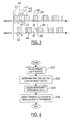
- FIG. 4 there is shown a logic flow diagram of a method of operating a night vision system in accordance with the anti-blinding scheme of Figure 3.
- the logic begins in step 200 by operating the night vision equipped vehicle's primary light source in a pulse mode at a duty cycle of less than approximately 50%.
- the light sensor determines first and second light intensity values corresponding to the detected light amount in the first half of the "off" time period and the second half of the time period when the primary light source is off. These two values are compared in block 204 to generate a ratio or difference value.
- the timing of the primary light source pulses is modified as a function of the difference value or ratio generated in block 204.
- the primary light source pulse timing can be modified in fixed increments so long as the ratio or difference value exceeds a threshold amount. In this way, when the light intensity values in the first and second time windows are approximately equal, the vehicle's primary night vision light source will be out-of-phase with any detected night vision light source from a similarly equipped vehicle.
- a night vision system in accordance with one embodiment of the present invention includes an illuminating device such as a NIR light source and beam-forming optics for illuminating a region in the forward direction of travel of the vehicle.
- a receiver such as a camera receives light reflected off objects in the illuminated region and generates a video signal responsive to the received light.
- a light sensor such as a photodiode, generates a light intensity signal in response to detecting light at approximately the same wavelength as light emitted by the pulsed light source.
- the controller is adapted to receive the light intensity signal during first and second time periods between pulses of the light source. The light intensity signals are compared during the first and second time periods, and the light source pulse timing is modified in response to a difference in the respective light intensity levels during the first and second time periods.
- the difference in light intensity levels during the respective time periods indicates that another source of light at approximately the same wavelength as the pulsed light source is present, but is not exactly in-phase or out-of-phase with the reference vehicle's pulsed light source.
- the timing of the pulsed light source is modified such that the light intensity levels during the inactive period are substantially constant. This is indicative of the oncoming vehicle's pulsed light source being exactly out-of-phase with the present vehicle's pulsed light source.
Abstract
Description
- The present invention relates to a night vision system for detecting objects at relatively low visible light levels. In particular, the invention concerns an active night vision system having an anti-blinding scheme employing pulsed illumination and synchronization with detected pulsed light sources from oncoming vehicles.
- Night vision systems are utilized to allow a user to see objects at relatively low visibility light levels. Night vision systems typically are classified as either passive night vision systems or active night vision systems. In known passive night vision systems used in automotive applications, mid-infrared cameras are used to image objects using the ambient infrared light emitted by the objects in the environment. Mid-infrared night vision systems have relatively few pixels and, accordingly, images formed using such cameras have low video resolution and a relatively narrow field of view. Known active night vision systems utilize a near-infrared (NIR) laser diode or a filtered incandescent light source to generate NIR light. The NIR light is subsequently reflected off objects in the environment and is received by a NIR-sensitive camera. The camera generates a video signal responsive to received light.
- An improved active night vision system is disclosed in U.S. Patent Application Serial No. 09/598,484 entitled "A Night Vision System Utilizing A Diode Laser Illumination Module And A Method Related Thereto," which is herein incorporated by reference. That application describes an active night vision system that uses a NIR diode laser to illuminate the region forward of the vehicle, and a CCD camera to process and display images within the illuminated region. Because NIR light is invisible to the human eye, the laser light can be formed into a high beam pattern to illuminate potential hazards without blinding oncoming vehicle operators. Such systems, however, are susceptible to blinding by oncoming vehicles similarly equipped with a night vision NIR light source.
- One solution to night vision system blinding by oncoming vehicles similarly equipped with a NIR light source is provided in U.S. Patent Application Serial No. 09/683,840 entitled "GPS-Based Anti-Blinding System For Active Night Vision." In that application, GPS is used to determine the direction of travel of the vehicles as well as an absolute time reference. Vehicles proximate one another synchronize their pulsed light sources to the absolute time reference signal with the phase of the light pulse based on the direction of motion of the respective vehicles. In this way, two cars approaching one another from opposite directions will have their NIR light sources pulsed out-of-phase with each other at duty cycles below 50% to avoid having their light source "on" when the opposing vehicle's camera is also "on." The disclosed anti-blinding scheme, however, requires that all night vision equipped vehicles must also be equipped with GPS systems.
- It is an object of this invention to provide an improved system and method for mitigating or eliminating blinding of the night vision system of a vehicle by similarly equipped approaching vehicles.
- According to a first aspect of the invention there is provided a night vision system for a vehicle characterised in that the system comprises a pulsed light source for illuminating a region proximate the vehicle operating at a predetermined pulse timing, a light sensor for generating a least one signal in response to detecting light and a controller programmed to receive the at least one signal from said light sensor and modify said light source pulse timing based upon the received signal or signals from the light sensor.
- It is an advantage of the invention that a less complicated and less expensive solution to the problem is provided than that provided by prior art systems and in particular GPS is not required.
- The light sensor may be operable to generate first and second light intensity signals corresponding to first and second time periods between pulses of the light source in response to detecting light at approximately the same wavelength as light from the light source and the controller may be further operable to compare the first and second light intensity signals and modify the light source pulse timing as a function of one of a difference between the first and second light intensity signals and a ratio between the first and second light intensity signals.
- The controller may be programmed to modify the light source pulse timing by a fixed amount when the ratio or difference value exceeds a threshold value.
- The controller may be programmed to modify the light source pulse timing by a variable amount related to the ratio or difference value.
- The controller may be programmed to modify the light source pulse timing to occur earlier when the first light intensity signal is greater than the second light intensity signal.
- Alternatively, the light sensor may be operable to generate a light change signal between pulses of the light source in response to detecting a change in intensity of light at approximately the same wavelength as light from the light source and the controller may be programmed to receive the light change signal from the light sensor corresponding to a time period between pulses of the light source and modify the light source pulse timing as a function of the light change signal.
- The light change value may be a high-to-low signal or low-to-high signal and the controller may be programmed to modify the light source pulse timing by a fixed amount in a direction corresponding to the light change signal.
- The light change value may be a high-to-low signal or low-to-high signal and the controller may be programmed to modify the light source pulse timing by a variable amount in a direction corresponding to the light change signal.
- The light change value may be a high-to-low signal or low-to-high signal and the controller may be programmed to modify the light source pulse timing to occur earlier when the light change signal is a high-to-low signal.
- In either case, the system may comprise a gated receiver for receiving light reflected off objects illuminated in the region by the pulsed light source and generating a signal responsive to the received light and the pulsed light source is a laser diode operating at a duty cycle of less than 50%.
- In either case, the light sensor may be one of a photocell, photodiode and a camera.
- According to a second aspect of the invention there is provided a method for an active night vision system for a vehicle characterised in that the method comprises pulse activating a light source to illuminate a region proximate the vehicle, the light source operating at a first wavelength and predetermined pulse timing, detecting light at the first wavelength during a first time period between respective pulses of the light source to generate a first light value and modifying the light source pulse timing based at least upon the first light value.
- The first light value may be a first light intensity value and the method may further comprise detecting light at the first wavelength during a second time period between respective pulses of the light source to generate a second light intensity value and modifying the light source pulse timing comprises modifying the light source pulse timing as a function of one of a ratio between the first and second light intensity values and a difference between the first and second light intensity values.
- Modifying may include modifying the light source pulse timing by a fixed amount when the ratio or difference value exceeds a threshold value.
- Modifying may include modifying the light source pulse timing by a variable amount related to the ratio or difference value.
- Pulse activating a light source may include operating a laser diode at a duty cycle of less than 50%.
- Alternatively, the first light value may be a light change signal representing a high-to-low light change or a low-to-high light change and modifying the light source pulse timing may comprise modifying the light source pulse timing as a function of the light change signal.
- Modifying may include modifying the light source pulse timing by a fixed amount in a direction related to the light change signal.
- Modifying may include modifying the light source pulse timing by a variable amount in a direction related to the light change signal.
- The invention will now be described by way of example with reference to the accompanying drawing of which:-
- Figure 1 is a schematic block diagram of a night vision system in accordance with one embodiment of the present invention.
- Figure 2 is a schematic diagram of a vehicle-operating environment in which the present invention may be used to advantage.
- Figure 3 is a graph showing the timing of the night vision signals for the vehicles of Figure 2 in accordance with one embodiment of the present invention.
- Figure 4 is a logic flow diagram of one method of operating the night vision system according to the present invention.
-
- Referring now to the drawings wherein like reference numerals are used to identify identical components in the various views, Figure 1 illustrates a
night vision system 10 for detecting objects at relatively low visibility light levels. Thesystem 10 may be utilized in a plurality of applications. For example, thesystem 10 may be used in an automotive vehicle to allow a driver to see objects at night that would not otherwise visible to the naked eye. As illustrated, thesystem 10 includes acontroller 11, anillumination subsystem 13, areceiver 15 and, in an alternate embodiment described below, asecondary light source 21. - Several of the system components may be included within a
housing 12. It should be understood, however, that the components ofsystem 10 contained withinhousing 12 could be disposed at different locations within the vehicle wherein thehousing 12 may not be needed. For example, the components of thesystem 10 could be disposed at different operative locations in the automotive vehicle such that asingle housing 12 would be unnecessary.Housing 12 is provided to enclose and protect the various components of thesystem 10.Housing 12 may be constructed from a plurality of materials including metals and plastics. - As will be discussed in more detail below, the
system 10 may be used to detect any reflective object, such asobject 24, in operative proximity to thesystem 10. - The
controller 11 is preferably a microprocessor-based controller including drive electronics for theillumination subsystem 13 andreceiver 15, and image processing logic for thedisplay system 30. In an alternate embodiment described below,controller 11 also includes drive electronics for thesecondary light source 21. Alternatively,display unit 30 may include its own respective control logic for generating and rendering image data. - The
illumination subsystem 13 includes aNIR light source 14, beam-formingoptics 16, and a coupler 17 between the two. Many light source and optics arrangements are contemplated by the present invention. For example, thelight source 14 may be a NIR diode laser, thebeam forming optics 16 may comprise a thin-sheet optical element followed by a holographic diffuser, whose combined purpose is to form a beam pattern in the direction of arrow A comparable to the high-beam pattern used for normal vehicle headlamps; and the coupler 17 between thelight source 14 andoptics 16 can be a fibre-optic cable. - The illumination subsystem illuminates the driving environment without blinding drivers in approaching vehicles, since the NIR light is not visible to the human eye. The
light source 14 may comprise a NIR diode laser or light-emitting diode, or any other NIR source that can be switched on and off at frequencies at or exceeding typical video frame rates (30-60 Hz). For example, thelight source 14 may include a single stripe diode laser, model number S-81-3000-C-200-H manufactured by Coherent, Inc. of Santa Clara, California. Further, the coupler may be a fibre-optic cable, or the light source could be directly coupled to theoptical element 16 through a rigid connector, in which case the coupler would be a simple lens or reflective component. The coupler 17, depending upon the spread characteristics of thelight source 14 may be omitted altogether. - Although the
system 10 preferably uses a NIR laser light source, an alternate embodiment ofsystem 10 may utilize a conventional light emitting diode NIR source, or any other type of NIR light source, as long as it is capable of pulsed operation, in lieu of the infrared diode laser. - The secondary
light source 21 is used as a trigger pulse light source. The secondary light source can comprise any type of pulsed light source but preferably is an infrared light source operating at a different wavelength than primarylight source 14. The secondarylight source 21 can be used to synchronize the gating of the primary light source andreceiver 15 to eliminate the blinding effects which are possible when two similarly equipped vehicles approach one another from opposite directions. - The secondary
light source 21 is also configured to emit light in the same direction as theillumination subsystem 13, which is indicated by direction arrow A corresponding to the forward direction of travel of the vehicle. - The secondary light source can also be configured to transmit light in the direction of indicator arrow B corresponding to the direction rearward of the vehicle. The rearwardly directed trigger pulse is used to synchronize the night vision illumination systems of commonly-equipped vehicles travelling in the same direction as described in further detail below with reference to Figure 4. If the same light source cannot be physically configured to emit light at the second wavelength in both direction A and direction B, two separate light sources may be necessary.
- In such a case, the additional light source would be a tertiary light source identical to the secondary light source. To distinguish light emitted by the secondary
light source 21 in direction A, from light emitted in direction B, the secondary light source is capable of transmitting pulses of different duration. The pulse width can then be used by other vehicles to determine whether the light detected from another vehicle's secondary light source came from the front of the other vehicle or rear of the other vehicle. Of course, characteristics other than, or in addition, to, pulse width can distinguish a forward trigger pulse (TF) from a rearward trigger pulse (TR) . For example, the wavelength of light may differ. - More than one rearward trigger pulse (TR1, TR2) may be necessary to convey synchronization information to vehicles following a reference vehicle. Thus, the secondary (or tertiary) light source includes the capability to further distinguish the normal rearward trigger pulse (TR1) from synchronized rearward trigger pulse (TR2) . Again, this characteristic may be a different pulse width and/or wavelength of light (third wavelength of light). Another distinguishing characteristic may include a double pulse.
- The
receiver 15 includes a NIR-sensitive camera 20 and opticalband pass filter 22. The NIR-sensitive camera 20 provides a video signal responsive to reflected infrared light received by thecamera 20. Thecamera 20 may comprise a CCD camera or a CMOS camera. In one embodiment of thesystem 10, the CCD camera is camera model number STC-H720 manufactured by Sentech Sensor Technologies America, Inc. - Infrared light emitted from the
illumination subsystem 13 and reflected off theobject 24 in the environment is received by the NIR-sensitive camera 20. The video signal is transmitted to thecontroller 11 or directly to thedisplay module 30 where it is processed and displayed to allow the vehicle operator to see theobject 24. Thedisplay 30 may be a television monitor, a CRT, LCD, or the like, or a heads-up-display positioned within the automotive vehicle to allow the user to see objects illuminated by thesystem 10. - The optical
band pass filter 22 is provided to filter the infrared light reflected from theobject 24. In particular, thefilter 22 only allows light within the NIR light spectrum to be received by thecamera 20. Preferably, thefilter 22 allows a maximum transmission of light at a wavelength equal to the wavelength of light generated by the NIRlight source 14. An advantage of using thefilter 22 is that thefilter 22 prevents saturation of the pixel elements (i.e., blooming) in thecamera 20 by visible light emitted from the headlamps of other automotive vehicles. Thefilter 22 is preferably disposed proximate to a receiving lens in thecamera 20. - The light sensor 19 in a first embodiment includes a photodiode or photocell or similar light sensor mounted in the
receiver module 15 and filtered, such as byband pass filter 22, to be sensitive only to light at the same wavelength as primarylight source 14. Alternatively, the average output signal of thecamera 20, spatially integrated over some or all of its field of view, could serve as the light sensor 19. In one embodiment, the light sensor 19 is configured to detect light at the wavelength corresponding to the secondarylight source 21. Preferably, the wavelength of light emitted by the secondary light source is different than the wavelength of light emitted by theprimary light source 14. - Referring now to Figure 2 there is shown a vehicle-operating environment wherein the present invention may be used to advantage. In Figure 2, two
vehicles vehicle 51 is shown followingvehicle 52. Bothvehicles night vision system 10 in accordance with the present invention. If the illumination sources ofvehicles vehicles - Referring now to Figure 3, there is shown a timing graph illustrating the night vision signals for the
vehicles reference numeral 60. The pulsed light source is being operated at a duty cycle of less than 50%. Similarly, thereceiver 15 and, in particular, thecamera 20 operates only during that portion of the cycle when the primary light source is on. Similarly, the pulsed light source of approaching vehicle 52 (Figure 2) is illustrated in the lower portion of Figure 3 wherein the primary light source pulses are indicated atreference numeral 62.Vehicle 52 also is operating its primary light source at a duty cycle below 50%. If the two approaching vehicles are able to coordinate their respective light pulses such that they are out-of-phase with each other, then night vision system blinding is avoided. As described herein, the light sensor 19 is used to ensure that the opposing night vision systems are synchronized out-of-phase with each other. - Specifically, in the first embodiment, the light sensor 19 is activated during the
interval 64 between time periods t3 and t5 when the primary light source is inactive. In other words, light source data is collected between adjacent pulses of the primary light source. Theinterval 64 between the laser pulses is divided into two approximately equallength time windows window first window 66 is represented byreference numeral 70 and the light intensity signal for thesubsequent window 68 is represented byreference numeral 72. Thelight intensity signal 70 is greater than thelight intensity signal 72 because the light sensor "sees" the light emitted by the opposing vehicle's primary light source (indicated as light pulse 62) for the duration of thefirst time window 66. In contrast, for the duration of thesecond time window 68, the light sensor is excited only a portion of the time by the opposing vehicle's primary light source. This difference in thelight intensity signal vehicle 50 that an approaching vehicle is emitting light at the wavelength of the primary light source which is not exactly in-phase or out-of-phase with that of the first vehicle's primary light source. - Thus, based on the initial arbitrary phase relationship shown for the pulsed primary light sources of
vehicle 50 andvehicle 52, the controller ofvehicle 50 detects that thefirst half 66 of thewindow 64 is "brighter" than thesecond half 68 of thewindow 64. Similarly, the controller ofvehicle 52 detects the opposite situation. In particular,vehicle 52 detects that the light intensity signal 74 in the first time period as less intense than thelight intensity signal 76 in the second time period of the interval between light pulses from the primary light source. - Referring again to
vehicle 50, because thelight intensity signal 70 during thefirst time period 66 is greater than thelight intensity signal 72 during thesecond time period 68, the controller ofvehicle 50 advances the next light pulse 80 from where it would have otherwise occurred as indicated by reference numeral 82. Similarly, with respect tovehicle 52, because the light intensity signal 74 during the first time period was less than thelight intensity signal 76 during the second time period during the interval between respective light pulses, the nextlight pulse 84 in sequence is delayed from the time in which it would have otherwise occurred as indicated by reference numeral 86. In succeeding pulses, further adjustments are made as necessary to bring the two pulse trains to a closely out-of-phase condition. The amount of the pulse delay or pulse advance can be either fixed or variable as a function of the relative difference between or ratio of the two light intensity signals 70, 72 in the case ofvehicle vehicle 52. - Alternatively, the light sensor 19 and associated electronics are activated as before during the
interval 64 between time periods t3 and t5 when the primary light source is inactive; however, rather than integrating the light received during this period, the sensor and electronics look for transitions in light intensity exceeding a threshold magnitude and abruptness. The transitions may be from low intensity to high intensity or vice versa. For example, with reference to Figure 3,vehicle 50 detects a single high to low transition at time t4 as the beam fromvehicle 52 is turned off, andvehicle 52 detects a single low to high transition at time t5 as the beam fromvehicle 50 is turned on. Detection of a single high to low transition causesvehicle 50 to shift its pulses slightly earlier; detection of a single low to hightransition cause vehicle 52 to shift its pulses slightly later. At some point the light pulses will cease to overlap and each car will see a low to high, followed by a high to low transition. Each car continues to adjust the phase of its light pulses until the other car's pulses are exactly centred between its own. - Alternatively, a vehicle detecting another night-vision-equipped vehicle approaching it, immediately switches the phase of its pulse train to be exactly out-of-phase with the approaching car, using either of the methods described above.
- Referring now to Figure 4 there is shown a logic flow diagram of a method of operating a night vision system in accordance with the anti-blinding scheme of Figure 3. The logic begins in
step 200 by operating the night vision equipped vehicle's primary light source in a pulse mode at a duty cycle of less than approximately 50%. Inblock 202 during the "off" time of the primary night vision light source, the light sensor determines first and second light intensity values corresponding to the detected light amount in the first half of the "off" time period and the second half of the time period when the primary light source is off. These two values are compared inblock 204 to generate a ratio or difference value. Inblock 206, the timing of the primary light source pulses is modified as a function of the difference value or ratio generated inblock 204. - Alternatively, the primary light source pulse timing can be modified in fixed increments so long as the ratio or difference value exceeds a threshold amount. In this way, when the light intensity values in the first and second time windows are approximately equal, the vehicle's primary night vision light source will be out-of-phase with any detected night vision light source from a similarly equipped vehicle.
- From the foregoing, it can be seen that there has been brought to the art a new and improved vehicle active night vision system which has advantages over prior vehicle night vision systems. The present invention provides an active night vision system and method related thereto which mitigates the blinding effects of nearby similarly equipped vehicles. The anti-blinding scheme of the present invention synchronizes the pulsed light sources of respective vehicles approaching each other from opposite directions to be out-of-phase without the use of GPS or any other external reference source. A night vision system in accordance with one embodiment of the present invention includes an illuminating device such as a NIR light source and beam-forming optics for illuminating a region in the forward direction of travel of the vehicle. A receiver, such as a camera, receives light reflected off objects in the illuminated region and generates a video signal responsive to the received light. A light sensor, such as a photodiode, generates a light intensity signal in response to detecting light at approximately the same wavelength as light emitted by the pulsed light source. The controller is adapted to receive the light intensity signal during first and second time periods between pulses of the light source. The light intensity signals are compared during the first and second time periods, and the light source pulse timing is modified in response to a difference in the respective light intensity levels during the first and second time periods. The difference in light intensity levels during the respective time periods indicates that another source of light at approximately the same wavelength as the pulsed light source is present, but is not exactly in-phase or out-of-phase with the reference vehicle's pulsed light source. Thus, the timing of the pulsed light source is modified such that the light intensity levels during the inactive period are substantially constant. This is indicative of the oncoming vehicle's pulsed light source being exactly out-of-phase with the present vehicle's pulsed light source.
- While the invention has been described in connection with one or more embodiments it will be appreciated that the invention is not limited to those embodiments and that various alternatives, modifications and equivalents could be constructed without departing from the scope of the invention.
Claims (10)
- A night vision system (10) for a vehicle characterised in that the system (10) comprises a pulsed light source (14) for illuminating a region proximate the vehicle operating at a predetermined pulse timing, a light sensor (19) for generating a least one signal in response to detecting light and a controller (11) programmed to receive the at least one signal from said light sensor (19) and modify said light source pulse timing based upon the received signal or signals from the light sensor (19).
- A night vision system as claimed in claim 1 wherein the light sensor (19) is operable to generate first and second light intensity signals corresponding to first and second time periods between pulses of the light source in response to detecting light at approximately the same wavelength as light from the light source (14) and the controller (11) is further operable to compare the first and second light intensity signals and modify the light source pulse timing as a function of one of a difference between the first and second light intensity signals and a ratio between the first and second light intensity signals.
- A night vision system as claimed in claim 2 wherein the controller (11) is programmed to modify the light source pulse timing by a fixed amount when the ratio or difference value exceeds a threshold value.
- A night vision system as claimed in claim 2 wherein the controller (11) is programmed to modify the light source pulse timing by a variable amount related to the ratio or difference value.
- A night vision system as claimed in claim 1 wherein the light sensor (19) is operable to generate a light change signal between pulses of the light source in response to detecting a change in intensity of light at approximately the same wavelength as light from the light source (14) and the controller (11) is programmed to receive the light change signal from the light sensor (19) corresponding to a time period between pulses of the light source and modify the light source pulse timing as a function of the light change signal.
- A night vision system as claimed in any of claims 1 to 5 wherein the system comprises a gated receiver for receiving light reflected off objects (24) illuminated in the region by the pulsed light source and generating a signal responsive to the received light and the pulsed light source (14) is a laser diode operating at a duty cycle of less than 50%.
- A night vision system as claimed in any of claims 1 to 6 wherein the light sensor (19) is one of a photocell, photodiode and a camera.
- A method for an active night vision system for a vehicle characterised in that the method comprises pulse activating a light source (14) to illuminate a region proximate the vehicle, the light source (14) operating at a first wavelength and predetermined pulse timing, detecting light at the first wavelength during a first time period between respective pulses of the light source (14) to generate a first light value and modifying the light source pulse timing based at least upon the first light value.
- A method as claimed in claim 8 wherein the first light value is a first light intensity value and the method further comprises detecting light at the first wavelength during a second time period between respective pulses of the light source to generate a second light intensity value and modifying the light source pulse timing comprises modifying the light source pulse timing as a function of one of a ratio between the first and second light intensity values and a difference between the first and second light intensity values.
- A method as claimed in claim 8 wherein the first light value is a light change signal representing a high-to-low light change or a low-to-high light change and modifying the light source pulse timing comprises modifying the light source pulse timing as a function of the light change signal.
Applications Claiming Priority (2)
| Application Number | Priority Date | Filing Date | Title |
|---|---|---|---|
| US64120 | 2002-06-12 | ||
| US10/064,120 US6828544B2 (en) | 2002-06-12 | 2002-06-12 | Active night vision system for vehicles employing anti-blinding scheme |
Publications (2)
| Publication Number | Publication Date |
|---|---|
| EP1376154A1 true EP1376154A1 (en) | 2004-01-02 |
| EP1376154B1 EP1376154B1 (en) | 2007-09-05 |
Family
ID=29717752
Family Applications (1)
| Application Number | Title | Priority Date | Filing Date |
|---|---|---|---|
| EP03101603A Expired - Fee Related EP1376154B1 (en) | 2002-06-12 | 2003-06-03 | An Active Night Vision System for a Motor Vehicle |
Country Status (3)
| Country | Link |
|---|---|
| US (1) | US6828544B2 (en) |
| EP (1) | EP1376154B1 (en) |
| DE (1) | DE60316074T2 (en) |
Cited By (13)
| Publication number | Priority date | Publication date | Assignee | Title |
|---|---|---|---|---|
| DE10334147A1 (en) * | 2003-07-26 | 2005-02-17 | Hella Kgaa Hueck & Co. | Infra-red imaging system for automobile using headlamp with lamp and filter for blocking visible light together with IR sensor coupled to display device |
| DE10343479A1 (en) * | 2003-09-19 | 2005-04-28 | Bosch Gmbh Robert | Method for improving the visibility in a motor vehicle |
| EP1538024A1 (en) * | 2003-12-05 | 2005-06-08 | Hitachi Ltd. | Apparatus for controlling auxiliary equipment of vehicle |
| DE10359192A1 (en) * | 2003-12-17 | 2005-07-14 | Hella Kgaa Hueck & Co. | Night vision system for motor vehicle, includes camera which records image in infrared range |
| GB2413904A (en) * | 2004-05-05 | 2005-11-09 | Lear Corp | Active night vision system with fully synchronized light source and receiver |
| WO2006011840A1 (en) * | 2004-07-30 | 2006-02-02 | Avalon Innovation Ab | A monitoring device |
| EP1632791A2 (en) * | 2004-09-04 | 2006-03-08 | Audi Aktiengesellschaft | Night vision system for a motor vehicle |
| WO2007009836A1 (en) * | 2005-07-20 | 2007-01-25 | Robert Bosch Gmbh | Image recording system |
| CN101794057B (en) * | 2010-01-20 | 2011-05-11 | 中国科学院半导体研究所 | Laser strobe active night vision method for remote night monitoring |
| US8536509B2 (en) | 2009-12-11 | 2013-09-17 | Bea Sa | Scanner arrangement |
| WO2017217745A1 (en) * | 2016-06-13 | 2017-12-21 | 엘지전자 주식회사 | Night vision display device |
| CN107776495A (en) * | 2012-03-16 | 2018-03-09 | 伟摩有限责任公司 | In view of the visual field of autonomous vehicle is actively changed in constraint |
| US20190187290A1 (en) * | 2016-06-13 | 2019-06-20 | Lg Electronics Inc. | Night vision display device |
Families Citing this family (19)
| Publication number | Priority date | Publication date | Assignee | Title |
|---|---|---|---|---|
| US7202776B2 (en) * | 1997-10-22 | 2007-04-10 | Intelligent Technologies International, Inc. | Method and system for detecting objects external to a vehicle |
| US7983802B2 (en) * | 1997-10-22 | 2011-07-19 | Intelligent Technologies International, Inc. | Vehicular environment scanning techniques |
| US6429429B1 (en) * | 2000-06-22 | 2002-08-06 | Ford Global Technologies, Inc. | Night vision system utilizing a diode laser illumination module and a method related thereto |
| US20020191388A1 (en) * | 2001-06-05 | 2002-12-19 | Oleg Matveev | Device and method for vehicular invisible road illumination and imaging |
| DE10146959A1 (en) * | 2001-09-24 | 2003-04-30 | Hella Kg Hueck & Co | Night vision device for vehicles |
| US7139411B2 (en) * | 2002-06-14 | 2006-11-21 | Honda Giken Kogyo Kabushiki Kaisha | Pedestrian detection and tracking with night vision |
| US7253570B2 (en) * | 2003-09-08 | 2007-08-07 | John Alfred Ayres | Automatic momentary secondary light source assembly |
| US7319805B2 (en) * | 2003-10-06 | 2008-01-15 | Ford Motor Company | Active night vision image intensity balancing system |
| JP4612635B2 (en) * | 2003-10-09 | 2011-01-12 | 本田技研工業株式会社 | Moving object detection using computer vision adaptable to low illumination depth |
| US6966681B2 (en) * | 2003-10-29 | 2005-11-22 | Ford Global Technologies Llc | Active night vision system for vehicles employing anti-blinding scheme |
| US7012551B2 (en) * | 2004-02-04 | 2006-03-14 | Ford Global Technologies, Llc | Method of anti-blinding for active night vision system |
| US20060017656A1 (en) * | 2004-07-26 | 2006-01-26 | Visteon Global Technologies, Inc. | Image intensity control in overland night vision systems |
| JPWO2007083741A1 (en) * | 2006-01-20 | 2009-06-11 | 住友電気工業株式会社 | Infrared imaging system |
| US7579593B2 (en) * | 2006-07-25 | 2009-08-25 | Panasonic Corporation | Night-vision imaging apparatus, control method of the same, and headlight module |
| JP2013534332A (en) * | 2010-07-19 | 2013-09-02 | ヘラ・カーゲーアーアー・ヒュック・ウント・コンパニー | Light source recognition method and apparatus |
| KR102512729B1 (en) * | 2015-12-24 | 2023-03-22 | 엘지전자 주식회사 | Night vision image display apparatus and method of processing the night vision image |
| RU2727547C2 (en) * | 2016-07-29 | 2020-07-22 | Святослав Иванович АРСЕНИЧ | Anti-dazzling system for illuminating a track with a vehicle |
| DE102016124594A1 (en) * | 2016-12-16 | 2018-06-21 | Jena-Optronik Gmbh | Method for detecting a 3D scene using a LIDAR system and LIDAR system for this purpose |
| US11780362B2 (en) | 2019-11-27 | 2023-10-10 | Hasco Vision Technology Co., Ltd. | Vehicle having a visible and non-visible lighting projection device with a light source mounted on a rotary actuator |
Citations (2)
| Publication number | Priority date | Publication date | Assignee | Title |
|---|---|---|---|---|
| DE10002069A1 (en) * | 2000-01-18 | 2001-08-09 | Daimler Chrysler Ag | Arrangement for improving visibility when viewing from a vehicle, has illumination lens with device for illumination direction dependent operation with compass for determining corresponding direction |
| DE10033103A1 (en) * | 2000-07-07 | 2002-01-17 | Siemens Ag | Infrared vision system |
Family Cites Families (6)
| Publication number | Priority date | Publication date | Assignee | Title |
|---|---|---|---|---|
| US4091412A (en) | 1967-12-01 | 1978-05-23 | The United States Of America As Represented By The Secretary Of The Army | Target designation system |
| US5050986A (en) | 1990-06-05 | 1991-09-24 | Motorola, Inc. | Synchronization system for controlling switches |
| US5519209A (en) | 1994-06-15 | 1996-05-21 | Alliedsignal Inc. | High range resolution active imaging system using a high speed shutter and a light pulse having a sharp edge |
| US5760887A (en) | 1996-04-30 | 1998-06-02 | Hughes Electronics | Multi-pulse, multi-return, modal range processing for clutter rejection |
| US6094160A (en) | 1999-06-10 | 2000-07-25 | Delco Electronics Corp. | Interference rejection method for an automotive radar CW/ICC system |
| US6576884B1 (en) * | 2001-06-20 | 2003-06-10 | Litton Systems, Inc. | Method and system for gating a sensor using a gating signal |
-
2002
- 2002-06-12 US US10/064,120 patent/US6828544B2/en not_active Expired - Lifetime
-
2003
- 2003-06-03 DE DE60316074T patent/DE60316074T2/en not_active Expired - Lifetime
- 2003-06-03 EP EP03101603A patent/EP1376154B1/en not_active Expired - Fee Related
Patent Citations (2)
| Publication number | Priority date | Publication date | Assignee | Title |
|---|---|---|---|---|
| DE10002069A1 (en) * | 2000-01-18 | 2001-08-09 | Daimler Chrysler Ag | Arrangement for improving visibility when viewing from a vehicle, has illumination lens with device for illumination direction dependent operation with compass for determining corresponding direction |
| DE10033103A1 (en) * | 2000-07-07 | 2002-01-17 | Siemens Ag | Infrared vision system |
Cited By (22)
| Publication number | Priority date | Publication date | Assignee | Title |
|---|---|---|---|---|
| DE10334147A1 (en) * | 2003-07-26 | 2005-02-17 | Hella Kgaa Hueck & Co. | Infra-red imaging system for automobile using headlamp with lamp and filter for blocking visible light together with IR sensor coupled to display device |
| DE10343479A1 (en) * | 2003-09-19 | 2005-04-28 | Bosch Gmbh Robert | Method for improving the visibility in a motor vehicle |
| US7415338B2 (en) | 2003-12-05 | 2008-08-19 | Hitachi, Ltd. | Apparatus for controlling auxiliary equipment of vehicle |
| EP1538024A1 (en) * | 2003-12-05 | 2005-06-08 | Hitachi Ltd. | Apparatus for controlling auxiliary equipment of vehicle |
| EP2077204A1 (en) * | 2003-12-05 | 2009-07-08 | Hitachi, Ltd. | Apparatus for controlling auxiliary equipment of vehicle |
| DE10359192A1 (en) * | 2003-12-17 | 2005-07-14 | Hella Kgaa Hueck & Co. | Night vision system for motor vehicle, includes camera which records image in infrared range |
| GB2413904A (en) * | 2004-05-05 | 2005-11-09 | Lear Corp | Active night vision system with fully synchronized light source and receiver |
| GB2413904B (en) * | 2004-05-05 | 2006-07-19 | Lear Corp | Active night vision system with fully synchronized light source and receiver |
| DE102005020950B4 (en) * | 2004-05-05 | 2009-03-12 | Lear Corp., Southfield | Active night vision system with fully synchronized light source and receiver |
| WO2006011840A1 (en) * | 2004-07-30 | 2006-02-02 | Avalon Innovation Ab | A monitoring device |
| US8279414B2 (en) | 2004-07-30 | 2012-10-02 | Avalon Innovation Ab | Monitoring device |
| EP1632791A3 (en) * | 2004-09-04 | 2007-05-02 | Audi Aktiengesellschaft | Night vision system for a motor vehicle |
| EP1632791A2 (en) * | 2004-09-04 | 2006-03-08 | Audi Aktiengesellschaft | Night vision system for a motor vehicle |
| WO2007009836A1 (en) * | 2005-07-20 | 2007-01-25 | Robert Bosch Gmbh | Image recording system |
| CN101223053B (en) * | 2005-07-20 | 2012-08-08 | 罗伯特·博世有限公司 | Image recording system |
| US8536509B2 (en) | 2009-12-11 | 2013-09-17 | Bea Sa | Scanner arrangement |
| CN101794057B (en) * | 2010-01-20 | 2011-05-11 | 中国科学院半导体研究所 | Laser strobe active night vision method for remote night monitoring |
| CN107776495A (en) * | 2012-03-16 | 2018-03-09 | 伟摩有限责任公司 | In view of the visual field of autonomous vehicle is actively changed in constraint |
| WO2017217745A1 (en) * | 2016-06-13 | 2017-12-21 | 엘지전자 주식회사 | Night vision display device |
| US20190187290A1 (en) * | 2016-06-13 | 2019-06-20 | Lg Electronics Inc. | Night vision display device |
| EP3471399A4 (en) * | 2016-06-13 | 2020-02-19 | LG Electronics Inc. -1- | Night vision display device |
| US11560091B2 (en) | 2016-06-13 | 2023-01-24 | Lg Electronics Inc. | Night vision display device |
Also Published As
| Publication number | Publication date |
|---|---|
| DE60316074T2 (en) | 2007-12-20 |
| US20030230705A1 (en) | 2003-12-18 |
| US6828544B2 (en) | 2004-12-07 |
| DE60316074D1 (en) | 2007-10-18 |
| EP1376154B1 (en) | 2007-09-05 |
Similar Documents
| Publication | Publication Date | Title |
|---|---|---|
| EP1376154B1 (en) | An Active Night Vision System for a Motor Vehicle | |
| EP1392054B1 (en) | An active night vision system for a vehicle | |
| US6966681B2 (en) | Active night vision system for vehicles employing anti-blinding scheme | |
| US6730913B2 (en) | Active night vision system for vehicles employing short-pulse laser illumination and a gated camera for image capture | |
| EP1562063B1 (en) | Night Vision System | |
| US7646884B2 (en) | Active night vision image intensity balancing system | |
| US6967569B2 (en) | Active night vision with adaptive imaging | |
| US6803574B2 (en) | Night vision device for vehicles | |
| CN100565273C (en) | Vehicle anti-glare system | |
| CN102047166B (en) | Device, camera, and method for generating images of the vicinity of a motor vehicle | |
| JP4204558B2 (en) | Image forming apparatus and image forming method | |
| US8009977B2 (en) | On-vehicle lighting apparatus | |
| US20070216769A1 (en) | Active 3D triangulation-based imaging method and device | |
| US20060018513A1 (en) | Stereo vehicle-exterior monitoring apparatus | |
| CN101223053A (en) | Image recording system | |
| JP2006023150A (en) | Infrared light projector, infrared imaging device, and vehicle | |
| JP2017502584A (en) | Method for operating a rear view camera system of an automobile after detection of a headlight flasher, a rear view camera system and an automobile | |
| JP2002274258A (en) | Night vision system for automobile | |
| US6690017B2 (en) | GPS-based anti-blinding system for active night vision | |
| GB2413904A (en) | Active night vision system with fully synchronized light source and receiver | |
| EP3605497A1 (en) | Illumination image capture device |
Legal Events
| Date | Code | Title | Description |
|---|---|---|---|
| PUAI | Public reference made under article 153(3) epc to a published international application that has entered the european phase |
Free format text: ORIGINAL CODE: 0009012 |
|
| AK | Designated contracting states |
Kind code of ref document: A1 Designated state(s): AT BE BG CH CY CZ DE DK EE ES FI FR GB GR HU IE IT LI LU MC NL PT RO SE SI SK TR |
|
| AX | Request for extension of the european patent |
Extension state: AL LT LV MK |
|
| RIN1 | Information on inventor provided before grant (corrected) |
Inventor name: STEPHAN, CRAIG, HAMMANN Inventor name: REMILLARD, JEFFREY, THOMAS |
|
| 17P | Request for examination filed |
Effective date: 20040702 |
|
| AKX | Designation fees paid |
Designated state(s): DE FR GB |
|
| RAP1 | Party data changed (applicant data changed or rights of an application transferred) |
Owner name: FORD GLOBAL TECHNOLOGIES, LLC. |
|
| GRAP | Despatch of communication of intention to grant a patent |
Free format text: ORIGINAL CODE: EPIDOSNIGR1 |
|
| GRAS | Grant fee paid |
Free format text: ORIGINAL CODE: EPIDOSNIGR3 |
|
| GRAJ | Information related to disapproval of communication of intention to grant by the applicant or resumption of examination proceedings by the epo deleted |
Free format text: ORIGINAL CODE: EPIDOSDIGR1 |
|
| GRAP | Despatch of communication of intention to grant a patent |
Free format text: ORIGINAL CODE: EPIDOSNIGR1 |
|
| GRAC | Information related to communication of intention to grant a patent modified |
Free format text: ORIGINAL CODE: EPIDOSCIGR1 |
|
| GRAS | Grant fee paid |
Free format text: ORIGINAL CODE: EPIDOSNIGR3 |
|
| GRAA | (expected) grant |
Free format text: ORIGINAL CODE: 0009210 |
|
| AK | Designated contracting states |
Kind code of ref document: B1 Designated state(s): DE FR GB |
|
| REG | Reference to a national code |
Ref country code: GB Ref legal event code: FG4D |
|
| REF | Corresponds to: |
Ref document number: 60316074 Country of ref document: DE Date of ref document: 20071018 Kind code of ref document: P |
|
| EN | Fr: translation not filed | ||
| PLBE | No opposition filed within time limit |
Free format text: ORIGINAL CODE: 0009261 |
|
| STAA | Information on the status of an ep patent application or granted ep patent |
Free format text: STATUS: NO OPPOSITION FILED WITHIN TIME LIMIT |
|
| 26N | No opposition filed |
Effective date: 20080606 |
|
| PG25 | Lapsed in a contracting state [announced via postgrant information from national office to epo] |
Ref country code: FR Free format text: LAPSE BECAUSE OF FAILURE TO SUBMIT A TRANSLATION OF THE DESCRIPTION OR TO PAY THE FEE WITHIN THE PRESCRIBED TIME-LIMIT Effective date: 20080502 |
|
| PGFP | Annual fee paid to national office [announced via postgrant information from national office to epo] |
Ref country code: GB Payment date: 20080506 Year of fee payment: 6 |
|
| GBPC | Gb: european patent ceased through non-payment of renewal fee |
Effective date: 20090603 |
|
| PG25 | Lapsed in a contracting state [announced via postgrant information from national office to epo] |
Ref country code: GB Free format text: LAPSE BECAUSE OF NON-PAYMENT OF DUE FEES Effective date: 20090603 |
|
| REG | Reference to a national code |
Ref country code: DE Ref legal event code: R082 Ref document number: 60316074 Country of ref document: DE Representative=s name: DOERFLER, THOMAS, DR.-ING., DE |
|
| PGFP | Annual fee paid to national office [announced via postgrant information from national office to epo] |
Ref country code: DE Payment date: 20160629 Year of fee payment: 14 |
|
| REG | Reference to a national code |
Ref country code: DE Ref legal event code: R119 Ref document number: 60316074 Country of ref document: DE |
|
| PG25 | Lapsed in a contracting state [announced via postgrant information from national office to epo] |
Ref country code: DE Free format text: LAPSE BECAUSE OF NON-PAYMENT OF DUE FEES Effective date: 20180103 |