EP1371409A1 - Separating film, separating film element, separating film module, sewage and waste water treatment device, and separating film manufacturing method - Google Patents
Separating film, separating film element, separating film module, sewage and waste water treatment device, and separating film manufacturing method Download PDFInfo
- Publication number
- EP1371409A1 EP1371409A1 EP02711312A EP02711312A EP1371409A1 EP 1371409 A1 EP1371409 A1 EP 1371409A1 EP 02711312 A EP02711312 A EP 02711312A EP 02711312 A EP02711312 A EP 02711312A EP 1371409 A1 EP1371409 A1 EP 1371409A1
- Authority
- EP
- European Patent Office
- Prior art keywords
- separation membrane
- porous
- porous substrate
- resin layer
- solvent
- Prior art date
- Legal status (The legal status is an assumption and is not a legal conclusion. Google has not performed a legal analysis and makes no representation as to the accuracy of the status listed.)
- Granted
Links
- 239000010865 sewage Substances 0.000 title claims description 20
- 238000004519 manufacturing process Methods 0.000 title description 3
- 238000004065 wastewater treatment Methods 0.000 title 1
- 229920005989 resin Polymers 0.000 claims abstract description 180
- 239000011347 resin Substances 0.000 claims abstract description 180
- 239000012528 membrane Substances 0.000 claims abstract description 166
- 238000000926 separation method Methods 0.000 claims abstract description 157
- 239000000758 substrate Substances 0.000 claims abstract description 110
- 239000011148 porous material Substances 0.000 claims abstract description 46
- 239000002131 composite material Substances 0.000 claims abstract description 30
- 238000000034 method Methods 0.000 claims abstract description 26
- 239000002245 particle Substances 0.000 claims abstract description 7
- 239000011859 microparticle Substances 0.000 claims abstract description 6
- 239000002904 solvent Substances 0.000 claims description 83
- 239000003795 chemical substances by application Substances 0.000 claims description 20
- 238000005345 coagulation Methods 0.000 claims description 17
- 230000015271 coagulation Effects 0.000 claims description 17
- 239000004745 nonwoven fabric Substances 0.000 claims description 14
- 239000002033 PVDF binder Substances 0.000 claims description 12
- 229920002981 polyvinylidene fluoride Polymers 0.000 claims description 12
- 239000002202 Polyethylene glycol Substances 0.000 claims description 11
- 238000001914 filtration Methods 0.000 claims description 11
- 229920001223 polyethylene glycol Polymers 0.000 claims description 11
- 238000011282 treatment Methods 0.000 claims description 11
- 239000000835 fiber Substances 0.000 claims description 8
- 239000011248 coating agent Substances 0.000 claims description 5
- 238000000576 coating method Methods 0.000 claims description 5
- 229920000642 polymer Polymers 0.000 claims description 3
- 239000012466 permeate Substances 0.000 abstract description 8
- 239000010410 layer Substances 0.000 description 104
- XLYOFNOQVPJJNP-UHFFFAOYSA-N water Substances O XLYOFNOQVPJJNP-UHFFFAOYSA-N 0.000 description 62
- 230000035699 permeability Effects 0.000 description 24
- 230000007423 decrease Effects 0.000 description 14
- FXHOOIRPVKKKFG-UHFFFAOYSA-N N,N-Dimethylacetamide Chemical compound CN(C)C(C)=O FXHOOIRPVKKKFG-UHFFFAOYSA-N 0.000 description 12
- 239000006185 dispersion Substances 0.000 description 8
- 229920000728 polyester Polymers 0.000 description 8
- 238000004626 scanning electron microscopy Methods 0.000 description 8
- ZMXDDKWLCZADIW-UHFFFAOYSA-N N,N-Dimethylformamide Chemical compound CN(C)C=O ZMXDDKWLCZADIW-UHFFFAOYSA-N 0.000 description 7
- 230000008569 process Effects 0.000 description 7
- 239000010802 sludge Substances 0.000 description 7
- IAZDPXIOMUYVGZ-UHFFFAOYSA-N Dimethylsulphoxide Chemical compound CS(C)=O IAZDPXIOMUYVGZ-UHFFFAOYSA-N 0.000 description 6
- OKKJLVBELUTLKV-UHFFFAOYSA-N Methanol Chemical compound OC OKKJLVBELUTLKV-UHFFFAOYSA-N 0.000 description 6
- 230000000052 comparative effect Effects 0.000 description 6
- 230000003247 decreasing effect Effects 0.000 description 6
- 239000010419 fine particle Substances 0.000 description 6
- 239000000203 mixture Substances 0.000 description 6
- -1 polypropylene Polymers 0.000 description 6
- 238000001878 scanning electron micrograph Methods 0.000 description 6
- 238000002835 absorbance Methods 0.000 description 5
- 239000000463 material Substances 0.000 description 5
- 238000012360 testing method Methods 0.000 description 5
- 239000011800 void material Substances 0.000 description 5
- 239000000243 solution Substances 0.000 description 4
- 239000002351 wastewater Substances 0.000 description 4
- ZWEHNKRNPOVVGH-UHFFFAOYSA-N 2-Butanone Chemical compound CCC(C)=O ZWEHNKRNPOVVGH-UHFFFAOYSA-N 0.000 description 3
- 241000233866 Fungi Species 0.000 description 3
- SECXISVLQFMRJM-UHFFFAOYSA-N N-Methylpyrrolidone Chemical compound CN1CCCC1=O SECXISVLQFMRJM-UHFFFAOYSA-N 0.000 description 3
- 239000004743 Polypropylene Substances 0.000 description 3
- 238000005273 aeration Methods 0.000 description 3
- 230000015572 biosynthetic process Effects 0.000 description 3
- 239000012267 brine Substances 0.000 description 3
- 239000000356 contaminant Substances 0.000 description 3
- 238000009826 distribution Methods 0.000 description 3
- 238000001471 micro-filtration Methods 0.000 description 3
- 229920001155 polypropylene Polymers 0.000 description 3
- HPALAKNZSZLMCH-UHFFFAOYSA-M sodium;chloride;hydrate Chemical compound O.[Na+].[Cl-] HPALAKNZSZLMCH-UHFFFAOYSA-M 0.000 description 3
- CSCPPACGZOOCGX-UHFFFAOYSA-N Acetone Chemical compound CC(C)=O CSCPPACGZOOCGX-UHFFFAOYSA-N 0.000 description 2
- VTYYLEPIZMXCLO-UHFFFAOYSA-L Calcium carbonate Chemical compound [Ca+2].[O-]C([O-])=O VTYYLEPIZMXCLO-UHFFFAOYSA-L 0.000 description 2
- LFQSCWFLJHTTHZ-UHFFFAOYSA-N Ethanol Chemical compound CCO LFQSCWFLJHTTHZ-UHFFFAOYSA-N 0.000 description 2
- PEDCQBHIVMGVHV-UHFFFAOYSA-N Glycerine Chemical compound OCC(O)CO PEDCQBHIVMGVHV-UHFFFAOYSA-N 0.000 description 2
- 239000004695 Polyether sulfone Substances 0.000 description 2
- 239000004698 Polyethylene Substances 0.000 description 2
- 229920000122 acrylonitrile butadiene styrene Polymers 0.000 description 2
- 230000001934 delay Effects 0.000 description 2
- 230000000694 effects Effects 0.000 description 2
- 238000001125 extrusion Methods 0.000 description 2
- 229920003023 plastic Polymers 0.000 description 2
- 239000004033 plastic Substances 0.000 description 2
- 229920002492 poly(sulfone) Polymers 0.000 description 2
- 229920006393 polyether sulfone Polymers 0.000 description 2
- 229920000573 polyethylene Polymers 0.000 description 2
- 239000004800 polyvinyl chloride Substances 0.000 description 2
- 229920000915 polyvinyl chloride Polymers 0.000 description 2
- 238000000746 purification Methods 0.000 description 2
- 239000008213 purified water Substances 0.000 description 2
- 238000001223 reverse osmosis Methods 0.000 description 2
- 125000006850 spacer group Chemical group 0.000 description 2
- 239000002344 surface layer Substances 0.000 description 2
- 238000005406 washing Methods 0.000 description 2
- 239000002759 woven fabric Substances 0.000 description 2
- 241000251468 Actinopterygii Species 0.000 description 1
- UXVMQQNJUSDDNG-UHFFFAOYSA-L Calcium chloride Chemical compound [Cl-].[Cl-].[Ca+2] UXVMQQNJUSDDNG-UHFFFAOYSA-L 0.000 description 1
- 229920003043 Cellulose fiber Polymers 0.000 description 1
- 229920002284 Cellulose triacetate Polymers 0.000 description 1
- 229920002430 Fibre-reinforced plastic Polymers 0.000 description 1
- 239000004697 Polyetherimide Substances 0.000 description 1
- 239000004793 Polystyrene Substances 0.000 description 1
- 239000004372 Polyvinyl alcohol Substances 0.000 description 1
- 229920002125 Sokalan® Polymers 0.000 description 1
- BZHJMEDXRYGGRV-UHFFFAOYSA-N Vinyl chloride Chemical compound ClC=C BZHJMEDXRYGGRV-UHFFFAOYSA-N 0.000 description 1
- NNLVGZFZQQXQNW-ADJNRHBOSA-N [(2r,3r,4s,5r,6s)-4,5-diacetyloxy-3-[(2s,3r,4s,5r,6r)-3,4,5-triacetyloxy-6-(acetyloxymethyl)oxan-2-yl]oxy-6-[(2r,3r,4s,5r,6s)-4,5,6-triacetyloxy-2-(acetyloxymethyl)oxan-3-yl]oxyoxan-2-yl]methyl acetate Chemical compound O([C@@H]1O[C@@H]([C@H]([C@H](OC(C)=O)[C@H]1OC(C)=O)O[C@H]1[C@@H]([C@@H](OC(C)=O)[C@H](OC(C)=O)[C@@H](COC(C)=O)O1)OC(C)=O)COC(=O)C)[C@@H]1[C@@H](COC(C)=O)O[C@@H](OC(C)=O)[C@H](OC(C)=O)[C@H]1OC(C)=O NNLVGZFZQQXQNW-ADJNRHBOSA-N 0.000 description 1
- XECAHXYUAAWDEL-UHFFFAOYSA-N acrylonitrile butadiene styrene Chemical compound C=CC=C.C=CC#N.C=CC1=CC=CC=C1 XECAHXYUAAWDEL-UHFFFAOYSA-N 0.000 description 1
- 239000004676 acrylonitrile butadiene styrene Substances 0.000 description 1
- 150000001298 alcohols Chemical class 0.000 description 1
- QVGXLLKOCUKJST-UHFFFAOYSA-N atomic oxygen Chemical compound [O] QVGXLLKOCUKJST-UHFFFAOYSA-N 0.000 description 1
- 229910000019 calcium carbonate Inorganic materials 0.000 description 1
- 239000001110 calcium chloride Substances 0.000 description 1
- 229910001628 calcium chloride Inorganic materials 0.000 description 1
- 238000010411 cooking Methods 0.000 description 1
- 239000011151 fibre-reinforced plastic Substances 0.000 description 1
- 238000005189 flocculation Methods 0.000 description 1
- 230000016615 flocculation Effects 0.000 description 1
- 238000001879 gelation Methods 0.000 description 1
- 235000011187 glycerol Nutrition 0.000 description 1
- 239000012510 hollow fiber Substances 0.000 description 1
- 238000005470 impregnation Methods 0.000 description 1
- 230000002401 inhibitory effect Effects 0.000 description 1
- 238000001746 injection moulding Methods 0.000 description 1
- 229910010272 inorganic material Inorganic materials 0.000 description 1
- 239000011147 inorganic material Substances 0.000 description 1
- 239000010954 inorganic particle Substances 0.000 description 1
- 239000004816 latex Substances 0.000 description 1
- 229920000126 latex Polymers 0.000 description 1
- 239000007788 liquid Substances 0.000 description 1
- 230000014759 maintenance of location Effects 0.000 description 1
- 238000005374 membrane filtration Methods 0.000 description 1
- 229910052751 metal Inorganic materials 0.000 description 1
- 239000002184 metal Substances 0.000 description 1
- 150000002739 metals Chemical class 0.000 description 1
- 244000005700 microbiome Species 0.000 description 1
- 239000011368 organic material Substances 0.000 description 1
- 229910052760 oxygen Inorganic materials 0.000 description 1
- 239000001301 oxygen Substances 0.000 description 1
- 230000036961 partial effect Effects 0.000 description 1
- 230000037361 pathway Effects 0.000 description 1
- 229920002037 poly(vinyl butyral) polymer Polymers 0.000 description 1
- 229920001601 polyetherimide Polymers 0.000 description 1
- 229920013716 polyethylene resin Polymers 0.000 description 1
- 229920001721 polyimide Polymers 0.000 description 1
- 239000009719 polyimide resin Substances 0.000 description 1
- 229920001451 polypropylene glycol Polymers 0.000 description 1
- 229920002223 polystyrene Polymers 0.000 description 1
- 229920002451 polyvinyl alcohol Polymers 0.000 description 1
- 238000001556 precipitation Methods 0.000 description 1
- 230000005855 radiation Effects 0.000 description 1
- 230000002829 reductive effect Effects 0.000 description 1
- 150000003839 salts Chemical class 0.000 description 1
- 239000004576 sand Substances 0.000 description 1
- 238000009287 sand filtration Methods 0.000 description 1
- 239000013535 sea water Substances 0.000 description 1
- 239000007787 solid Substances 0.000 description 1
- 239000011343 solid material Substances 0.000 description 1
- 229910001220 stainless steel Inorganic materials 0.000 description 1
- 239000010935 stainless steel Substances 0.000 description 1
- 239000000126 substance Substances 0.000 description 1
- 239000008400 supply water Substances 0.000 description 1
- 238000000108 ultra-filtration Methods 0.000 description 1
- 238000000870 ultraviolet spectroscopy Methods 0.000 description 1
- 229920003169 water-soluble polymer Polymers 0.000 description 1
- 238000003466 welding Methods 0.000 description 1
- 238000004804 winding Methods 0.000 description 1
Images


Classifications
-
- B—PERFORMING OPERATIONS; TRANSPORTING
- B01—PHYSICAL OR CHEMICAL PROCESSES OR APPARATUS IN GENERAL
- B01D—SEPARATION
- B01D69/00—Semi-permeable membranes for separation processes or apparatus characterised by their form, structure or properties; Manufacturing processes specially adapted therefor
- B01D69/08—Hollow fibre membranes
-
- B—PERFORMING OPERATIONS; TRANSPORTING
- B01—PHYSICAL OR CHEMICAL PROCESSES OR APPARATUS IN GENERAL
- B01D—SEPARATION
- B01D71/00—Semi-permeable membranes for separation processes or apparatus characterised by the material; Manufacturing processes specially adapted therefor
- B01D71/06—Organic material
- B01D71/30—Polyalkenyl halides
- B01D71/32—Polyalkenyl halides containing fluorine atoms
- B01D71/34—Polyvinylidene fluoride
-
- B—PERFORMING OPERATIONS; TRANSPORTING
- B01—PHYSICAL OR CHEMICAL PROCESSES OR APPARATUS IN GENERAL
- B01D—SEPARATION
- B01D61/00—Processes of separation using semi-permeable membranes, e.g. dialysis, osmosis or ultrafiltration; Apparatus, accessories or auxiliary operations specially adapted therefor
- B01D61/14—Ultrafiltration; Microfiltration
- B01D61/18—Apparatus therefor
-
- B—PERFORMING OPERATIONS; TRANSPORTING
- B01—PHYSICAL OR CHEMICAL PROCESSES OR APPARATUS IN GENERAL
- B01D—SEPARATION
- B01D63/00—Apparatus in general for separation processes using semi-permeable membranes
- B01D63/08—Flat membrane modules
- B01D63/081—Manufacturing thereof
-
- B—PERFORMING OPERATIONS; TRANSPORTING
- B01—PHYSICAL OR CHEMICAL PROCESSES OR APPARATUS IN GENERAL
- B01D—SEPARATION
- B01D63/00—Apparatus in general for separation processes using semi-permeable membranes
- B01D63/08—Flat membrane modules
- B01D63/082—Flat membrane modules comprising a stack of flat membranes
- B01D63/0822—Plate-and-frame devices
-
- B—PERFORMING OPERATIONS; TRANSPORTING
- B01—PHYSICAL OR CHEMICAL PROCESSES OR APPARATUS IN GENERAL
- B01D—SEPARATION
- B01D63/00—Apparatus in general for separation processes using semi-permeable membranes
- B01D63/10—Spiral-wound membrane modules
-
- B—PERFORMING OPERATIONS; TRANSPORTING
- B01—PHYSICAL OR CHEMICAL PROCESSES OR APPARATUS IN GENERAL
- B01D—SEPARATION
- B01D65/00—Accessories or auxiliary operations, in general, for separation processes or apparatus using semi-permeable membranes
- B01D65/08—Prevention of membrane fouling or of concentration polarisation
-
- B—PERFORMING OPERATIONS; TRANSPORTING
- B01—PHYSICAL OR CHEMICAL PROCESSES OR APPARATUS IN GENERAL
- B01D—SEPARATION
- B01D67/00—Processes specially adapted for manufacturing semi-permeable membranes for separation processes or apparatus
- B01D67/0002—Organic membrane manufacture
- B01D67/0009—Organic membrane manufacture by phase separation, sol-gel transition, evaporation or solvent quenching
- B01D67/0011—Casting solutions therefor
-
- B—PERFORMING OPERATIONS; TRANSPORTING
- B01—PHYSICAL OR CHEMICAL PROCESSES OR APPARATUS IN GENERAL
- B01D—SEPARATION
- B01D67/00—Processes specially adapted for manufacturing semi-permeable membranes for separation processes or apparatus
- B01D67/0002—Organic membrane manufacture
- B01D67/0009—Organic membrane manufacture by phase separation, sol-gel transition, evaporation or solvent quenching
- B01D67/0016—Coagulation
- B01D67/00165—Composition of the coagulation baths
-
- B—PERFORMING OPERATIONS; TRANSPORTING
- B01—PHYSICAL OR CHEMICAL PROCESSES OR APPARATUS IN GENERAL
- B01D—SEPARATION
- B01D67/00—Processes specially adapted for manufacturing semi-permeable membranes for separation processes or apparatus
- B01D67/0002—Organic membrane manufacture
- B01D67/0023—Organic membrane manufacture by inducing porosity into non porous precursor membranes
- B01D67/003—Organic membrane manufacture by inducing porosity into non porous precursor membranes by selective elimination of components, e.g. by leaching
-
- B—PERFORMING OPERATIONS; TRANSPORTING
- B01—PHYSICAL OR CHEMICAL PROCESSES OR APPARATUS IN GENERAL
- B01D—SEPARATION
- B01D69/00—Semi-permeable membranes for separation processes or apparatus characterised by their form, structure or properties; Manufacturing processes specially adapted therefor
- B01D69/02—Semi-permeable membranes for separation processes or apparatus characterised by their form, structure or properties; Manufacturing processes specially adapted therefor characterised by their properties
-
- B—PERFORMING OPERATIONS; TRANSPORTING
- B01—PHYSICAL OR CHEMICAL PROCESSES OR APPARATUS IN GENERAL
- B01D—SEPARATION
- B01D69/00—Semi-permeable membranes for separation processes or apparatus characterised by their form, structure or properties; Manufacturing processes specially adapted therefor
- B01D69/10—Supported membranes; Membrane supports
- B01D69/108—Inorganic support material
-
- B—PERFORMING OPERATIONS; TRANSPORTING
- B01—PHYSICAL OR CHEMICAL PROCESSES OR APPARATUS IN GENERAL
- B01D—SEPARATION
- B01D69/00—Semi-permeable membranes for separation processes or apparatus characterised by their form, structure or properties; Manufacturing processes specially adapted therefor
- B01D69/12—Composite membranes; Ultra-thin membranes
-
- B—PERFORMING OPERATIONS; TRANSPORTING
- B01—PHYSICAL OR CHEMICAL PROCESSES OR APPARATUS IN GENERAL
- B01D—SEPARATION
- B01D2315/00—Details relating to the membrane module operation
- B01D2315/06—Submerged-type; Immersion type
-
- B—PERFORMING OPERATIONS; TRANSPORTING
- B01—PHYSICAL OR CHEMICAL PROCESSES OR APPARATUS IN GENERAL
- B01D—SEPARATION
- B01D2321/00—Details relating to membrane cleaning, regeneration, sterilization or to the prevention of fouling
- B01D2321/18—Use of gases
- B01D2321/185—Aeration
-
- B—PERFORMING OPERATIONS; TRANSPORTING
- B01—PHYSICAL OR CHEMICAL PROCESSES OR APPARATUS IN GENERAL
- B01D—SEPARATION
- B01D2323/00—Details relating to membrane preparation
- B01D2323/08—Specific temperatures applied
-
- B—PERFORMING OPERATIONS; TRANSPORTING
- B01—PHYSICAL OR CHEMICAL PROCESSES OR APPARATUS IN GENERAL
- B01D—SEPARATION
- B01D2323/00—Details relating to membrane preparation
- B01D2323/12—Specific ratios of components used
-
- B—PERFORMING OPERATIONS; TRANSPORTING
- B01—PHYSICAL OR CHEMICAL PROCESSES OR APPARATUS IN GENERAL
- B01D—SEPARATION
- B01D2325/00—Details relating to properties of membranes
- B01D2325/04—Characteristic thickness
-
- C—CHEMISTRY; METALLURGY
- C02—TREATMENT OF WATER, WASTE WATER, SEWAGE, OR SLUDGE
- C02F—TREATMENT OF WATER, WASTE WATER, SEWAGE, OR SLUDGE
- C02F1/00—Treatment of water, waste water, or sewage
- C02F1/44—Treatment of water, waste water, or sewage by dialysis, osmosis or reverse osmosis
- C02F1/444—Treatment of water, waste water, or sewage by dialysis, osmosis or reverse osmosis by ultrafiltration or microfiltration
Definitions
- the present invention relates to a separation membrane suitably used in purification of sewage, namely, domestic wasted water exhausted from life environments such as cooking, washing, taking a bath, and relieving nature, and of wastewater discharged from manufacturing plants, restaurants, fish processing factories, and food processing factories.
- the present invention also relates to a method for making the separation membrane.
- the present invention relates to a separation membrane element, a separation membrane module, and a sewage treatment apparatus including the separation membrane.
- microfiltration membrane Separation membranes have recently been used for purification of sewage and wastewater. Though various types and shapes of separation membrane are known, a flat membrane called a microfiltration membrane attracts attention.
- the microfiltration membrane is generally formed as follows. A resin solution containing a pore-forming agent is applied onto a surface of a porous substrate such as woven or nonwoven fabric or is impregnated into the porous substrate, and the resin is coagulated to form a porous resin layer on the porous substrate. The porous resin layer functions as a separation layer.
- the flat membrane does not have a large effective area per unit area, compared with other types of separation membrane, for example, a hollow fiber membrane; hence, the flat membrane is required for achieving high water permeability while maintaining a micropore size corresponding to the object to be filtered.
- the porosity is increased in order to achieve high water permeability
- the micropore size excessively increases or surface cracks causing a decrease in rejection occurs.
- the micropore size is decreased in order to achieve a high rejection, the water permeability inevitably decreases. Accordingly, a high rejection and high water permeability are basically incompatible. It is difficult to achieving balanced compatibility therebetween.
- separation membranes for sewage water undergo heavy collision of solid materials such as sand and sludge in use and heavy collision of bubbles during an aeration process which is performed to supply oxygen into activated sludge and to prevent clogging.
- the separation membrane must have sufficiently high strength durable to such severe impacts. Such high strength is primarily borne by the porous substrate.
- the porous resin layer would be separated from the porous substrate during a filtration process and an aeration process in severe cases.
- a separation membrane comprises a porous substrate and a porous resin layer on at least one surface of the porous substrate, the porous resin layer comprising a resin, part of the resin permeating into the porous substrate to form a composite layer with the porous substrate, wherein at least one of the following relationships (1) and (2) is satisfied: (1) the porous resin layer has an average pore size in the range of 0.01 to 0.2 ⁇ m and a standard variation of the pore size of 0.1 ⁇ m or less at the surface; and (2) the porous resin layer has macrovoids having short diameters of 0.05 ⁇ A or more wherein A represents the thickness of the porous substrate, and the rejection of micro particles having an average particle size of 0.9 ⁇ m is at least 90%.
- the average pore size and the standard deviation are determined based on diameters of all micropores which can be observed in a scope of 9.2 ⁇ m by 10.4 ⁇ m by scanning electron microscopy at a magnification of ⁇ 10,000.
- a method for making a separation membrane comprises the steps of applying a solvent containing a resin, a pore-forming agent, and a solvent onto at least one surface of a porous substrate having a density of 0.7 g/cm 3 or less to form a coating film and to impregnate the porous substrate with the solvent; and immersing the porous substrate into a coagulation bath containing a non-solvent to coagulate the resin and to form a porous resin layer on the surface of the porous substrate.
- the present invention is directed to a separation membrane element including the separation membrane, a separation membrane module including the separation membrane elements, and a sewage treatment apparatus including the separation membrane module.
- the separation membrane according to the present invention comprises a porous substrate and a porous resin layer, which functions as a separation layer, on at least one surface of the porous substrate.
- the porous resin layer comprises a resin and part of the resin permeates into the porous substrate to form a composite layer with the porous substrate.
- the porous resin layer does not include the composite layer.
- the porous substrate supports the porous resin layer and imparts strength to the separation membrane.
- Both organic materials and inorganic materials can be used as the porous substrate, and organic fibers are preferably used since they are lightweight.
- More preferable porous substrates are woven or nonwoven fabrics of organic fibers such as cellulose fibers, cellulose triacetate fibers, polyester fibers, polypropylene fibers, and polyethylene fibers.
- nonwoven fabrics are preferable because the control of density is easy and the nonwoven fabrics can be readily produced with reduced costs.
- a significantly thin porous substrate does not have a sufficient strength for the use in the separation membrane, and a significantly thick porous substrate causes a decrease in water permeability.
- the thickness of the porous substrate is preferably in the range of 50 ⁇ m to 1 mm, and more preferably 70 ⁇ m to 500 ⁇ m.
- the porous resin layer functions as a separation layer.
- materials used for the porous resin layer include polyethylene resins, polypropylene resins, polyvinyl chloride resins, polyvinylidene fluoride resins, polysulfone resins, polyethersulfone resins, polyimide resins, and polyether imide resins. These resins may contain other resins, as long as these resins are primary components.
- the "primary components" means that at least 50% and preferably at least 60% of the above resin is contained.
- polyvinyl chloride resins polyvinylidene fluoride resins
- polysulfone resins polysulfone resins
- polyethersulfone resins since films can be readily formed from these resins by a solution process and these resins exhibit high mechanical and chemical resistances.
- the most preferable resins are polyvinylidene fluoride and mixtures containing polyvinylidene fluoride as the primary component.
- the thickness of the porous resin layer is preferably in the range of 1 ⁇ m to 500 ⁇ m and more preferably in the range of 5 ⁇ m to 200 ⁇ m.
- a significantly thin porous resin causes exposition of the porous substrate, resulting in adhesion of contaminants to the porous substrate. In such a case, the filtration pressure will increase and the filtering performance may not be restored sufficiently after washing.
- a significantly thick porous resin layer may cause a decrease in water permeability.
- Part of the resin of the porous resin layer permeates into at least the surface layer of the porous substrate to form a composite layer with the porous substrate at least at the surface layer.
- the resin permeating into the porous substrate is firmly fixed on the porous substrate by the co-called “anchor effect" and is not detached from the porous substrate.
- the porous resin layer may be formed on one surface of the porous substrate or the porous resin layers may be formed on both surfaces thereof. If the porous resin layer is provided on one surface, the separation membrane with high water permeability can be readily formed. If the porous resin layers are provided on two surfaces, the separation membrane can maintain high performance in use for a long time.
- the porous resin layers may be symmetrical or asymmetrical to the porous substrate. Also if the porous resin layers are provided on both surfaces, the both porous resin layers may be continuous through the composite layer or may be discontinuous.
- the separation membrane according to the present invention has an average pore diameter in the range of 0.01 ⁇ m to 0.2 ⁇ m and a standard deviation of pore size of 0.1 ⁇ m or less at the surface of the porous resin layer.
- the separation membrane satisfying such ranges exhibits both a high permeability for a long time without clogging and a high rejection, which means that fungus and sludge do not leak.
- a smaller average pore size may cause decreased water permeability.
- the average pore size is preferably at least 0.02 ⁇ m and more preferably at least 0.04 ⁇ m. If the porous resin layers are provided on two surfaces of the porous substrate, at least one of the porous resin layers must satisfy the above conditions.
- the average pore size and the standard deviation are determined based on diameters of all micropores which can be observed in a scope of 9.2 ⁇ m by 10.4 ⁇ m by scanning electron microscopy at a magnification of ⁇ 10,000.
- the separation membrane according to the present invention satisfies the following inequalities: B ⁇ 0.2 ⁇ A, and C/B ⁇ 0.1 wherein A represents the thickness of the porous substrate, B represents the thickness of the porous resin layer, and C represents the thickness of the composite layer. If the thickness of the porous resin layer is smaller than 0.2 ⁇ A, the strength is insufficient to the separation layer. If the ratio C/B is smaller than 0.1, the porous resin layer is readily detached from the porous substrate. On the contrary, if the ratio C/B is extraordinarily large, the water permeability will decrease. Thus, the ratio C/B generally satisfies the following relationship: 0.1 ⁇ C/B ⁇ 100 and preferably 0.2 ⁇ C/B ⁇ 50.
- the porous resin layer contains macrovoids having specific sizes.
- the "macrovoids” means pores which are present in the porous resin layer and have larger diameters than the pore diameter at the surface.
- the macrovoids are useful for maintaining the strength of the porous resin layer while improving the water permeability.
- the macrovoids have short diameters of at least 0.05 ⁇ A. A smaller short diameter causes a significant decrease in water permeability, though it increases the strength of the porous resin layer. On the other hand, an extraordinarily large short diameter causes decreased strength of the porous resin layer.
- the upper limit of sizes of the macrovoids is preferably 1 ⁇ A or less.
- the thickness of the porous resin layer, the thickness of the composite layer, and the sizes of the macrovoids in the porous resin layer can be determined by observing a cross-section perpendicular to the surface of the porous resin layer with a scanning electron microscope.
- porous resin layers are provided on two surfaces, the following inequalities are preferably satisfied: 2d A ⁇ d C 2 d B ⁇ d C wherein d A represents the average pore size at the surface of one of the porous resin layers, d B represents the average pore size at the surface of the other porous resin layer, and d c represents the average pore size in the central cross-section of the separation membrane in the thickness direction.
- d A represents the average pore size at the surface of one of the porous resin layers
- d B represents the average pore size at the surface of the other porous resin layer
- d c represents the average pore size in the central cross-section of the separation membrane in the thickness direction.
- the rejection of micro particles having an average particle size of 0.9 ⁇ m is preferably at least 90%.
- a rejection of less than 90% causes leakage of fungus and sludge, clogging due to fungus and sludge, an increased differential filtration pressure, and a significantly decreased life.
- the rejection is determined as follows.
- the stock dispersion Using a stock dispersion containing purified water through a reverse osmosis membrane and 10 ppm of polystyrene latex microparticles having an average diameter of 0.9 ⁇ m (nominal diameter: 0.940 ⁇ m, the standard deviation: 0.0796 ⁇ m), the stock dispersion is allowed to permeate through the separation membrane at a head height of 1 m while the stock dispersion is stirred.
- the separation membrane according to the present invention may be combined with a support to prepare a separation membrane element.
- the separation membrane according to the present invention is arranged on at least one surface of a supporting plate as the support.
- This separation membrane element can be preferably used in sewage treatments as described below.
- the separation membranes are preferably arranged on both surfaces of the supporting plate to increase water permeability.
- the configuration of the separation membrane element is not limited. Preferable configurations of the separation membrane element will now be described with reference to the drawings.
- the element has a rigid supporting plate 1, and channel members 2 and separation membranes 3 arranged on both surfaces of the supporting plate 1 in that order.
- the supporting plate 1 has projections 4 and recesses 5.
- the contaminants in the liquid are removed by the separation membrane 3.
- the channel members 2 are provided so that water permeating through the separation membrane 3 effectively flows toward the supporting plate 1.
- the filtered water reaching the supporting plate 1 flows in the recesses of the supporting plate 1 toward the exterior.
- any supporting plate 1 may be used in the present invention as long as a plurality of projections and recesses are provided both surfaces of a plate.
- the recesses constitute a plurality of grooves arranged in parallel at a constant pitch so that the distance to the outlet for the filtered water and the channel resistance become uniform. In such a configuration, the filtered water uniformly flows on the membrane.
- the width of the recesses is preferably in the range of 1 mm to 20 mm and more preferably 1.5 mm to 5 mm to maintain high water permeability and to prevent sinking of the channel members 2 and the separation membranes 3 under severe aeration conditions.
- the depth of the recesses 5 is determined within the range of 1 mm to 10 mm to suppress the thickness of the element and to secure channels for the filtered water.
- the void fraction formed by the recesses of the supporting plate is preferably in the range of 15% to 85% to keep the strength of the supporting plate and to suppress the flow resistance of the filtered water.
- the void fraction means the volume fraction of voids formed by the recesses to a void fraction of a hollow rectangular parallelepiped of 100%. At a void fraction of less than 15%, the flow resistance is too high to effectively collect the filtered water. At a void fraction exceeding 85%, the strength of the supporting plate significantly decreases.
- the supporting plate 1 is preferably composed of a rigid material having a tensile strength of about 15 MPa according to ASTM testing method D638.
- preferable materials are metals such as stainless steel; resins such as acrylonitrile-butadiene-styrene copolymers (ABS resins), polyethylene, polypropylene, and vinyl chloride; and composite materials such as fiber-reinforced plastics (RFP).
- the channel member 2 preferably has a thickness in the range of 0.1 mm to 5 mm to decrease the thickness of the element while maintaining the flow channels. It is preferable that a material having a high porosity such as a plastic net be used to reduce pressure drop.
- the porosity of the channel member is preferably in the range of 40% to 96%.
- the separation membrane element according to the present invention is preferably provided with a frame 6 at the periphery of the supporting plate 1.
- the separation membrane 3 may be disposed between the supporting plate 1 and the frame 6 or may be fixed onto the outer surface of the frame 6.
- the fixing process may be a bonding process using a resin, a welding process of the separation membrane itself, and any other bonding process.
- the frame 6, which is formed by injection molding or extrusion, may be engaged on the periphery of the supporting plate 1, which is formed by economical extrusion, to suppress fabrication costs.
- the frame 6 preferably has a U-shaped cross-section so that the supporting plate 1 can be readily engaged.
- the water permeating through the separation membrane 3 flows in the channel member 2 and the recesses 5 of the supporting plate 1 toward the exterior of the element through a filtered water outlet 7.
- the separation membrane according to the present invention can be preferably used in sewage treatment apparatuses.
- the method for using the separation membrane is not limited. A preferable method for use will be described below.
- a plurality of the elements 9 are accommodated in parallel to each other in the housing so as to form a space between the surfaces of the separation membranes 3 (Fig. 7), in order to form the separation membrane module 10.
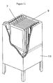
- This separation membrane module 10 as shown in Fig. 12, is used by immersing into water to be treated such as organic wastewater stored in a reservoir 11.
- the separation membrane module 10 has a plurality of the elements 9 which are vertically arranged and an air diffuser 12 for supplying air from a blower 13 to the surfaces of the separation membranes therein, and has a pump 14, which sucks in filtered water, downstream of the separation membrane module 10.
- water to be treated such as wastewater
- water permeating through the separation membranes 3 by the suction force of the pump 14 and suspended solids such as microorganism particles and inorganic particles which do not permeate.
- the water permeating through the separation membranes 3 flows through a flow pathway formed of the channel member 2, the recesses 5 of a supporting plate 1, a collecting conduit 8 formed in the frame 6, and the filtered water outlet 7 toward the exterior of the reservoir 11.
- the air diffuser 12 generates bubbles, which generate an upward flow parallel to the surfaces of the membranes of the elements 9 by the airlift effect. The upward flow removes the filtration residue deposited on the surfaces of the membranes.
- Another preferable embodiment of the separation membrane element according to the present invention has a container and a spirally wound separation membrane according to the present invention accommodated in the container.
- the element in this embodiment will now be described with reference to Fig. 13.
- a separation membrane element 15 includes folded separation membranes 18, each containing a mesh spacer 19. These separation membranes 18 are spirally wounded around a central pipe 16 together with channel members 17.
- a brine seal 20 is provided at one end of the winding structure. In each element 15, supply water having a given pressure from the brine seal 20 flows through the mesh spacer 19 and permeates through the separation membrane 18. The filtered water is collected through the central pipe 16.
- This element has a larger membrane area and thus has high water permeability compared with the above-described elements including the supporting plate. Since this element, however, exhibit relatively low supply effectively due to retention of contaminants at the supply side; this is suitable for treatment of seawater, brine, and river water.
- the activated-sludge effluent is preliminarily treated by flocculation and precipitation, sand filtration, micro filtration membrane, or ultra filtration membrane.
- the preliminary treatments may be employed alone or in combination.
- the separation membrane according to the present invention may be produced by the following method.
- a coating film is formed on a surface or surfaces of the above-described porous substrate with a solvent containing the above-described resin, a pore-forming agent, and a solvent, and the porous substrate is impregnated with the solvent. Then, the porous substrate is immersed into a coagulation bath containing a non-solvent to coagulate the resin and to form a porous resin layers on the surfaces of the porous substrate.
- the solvent contains a non-solvent.
- the temperature of the solvent is preferably selected from the range of 15°C to 120°C in view of film formability.
- the density of the porous substrate is preferably 0.7 g/cm 3 or less and more preferably 0.6 g/cm 3 or less.
- the porous substrate can hold the resin forming the porous resin layer, so that an adequate composite layer or composite layers of the porous substrate and the resin is formed. Since a significantly low density causes a decreased in strength of the separation membrane, the density is preferably at least 0.3 g/cm 3 .
- the density represents an apparent density, which can be determined from the area, the thickness, and the weight of the porous substrate.
- the pore-forming agent is extracted from the resin layer to form pores in the resin layer when the porous substrate is immersed in the coagulation bath.
- the pore-forming agent has high solubility in the coagulation bath.
- the pore-forming agents are inorganic salts such as calcium chloride and calcium carbonate.
- the pore-forming agents may be polyoxyalkylenes, e.g., polyethylene glycol and polypropylene glycol; and water-soluble polymers, e.g., polyvinyl alcohol, polyvinyl butyral, and polyacrylic acids; and glycerin.
- the pore-forming agent may be appropriately selected according to the resin.
- a polymer primarily containing polyethylene glycol is preferable. More preferably, a polymer primarily containing polyethylene glycol having a weight average molecular weight of at least 10,000 is used in view of balance among the surface pore size, pore size distribution, and permeability.
- the solvent dissolves the resin.
- the solvent acts on the resin and the pore-forming agent and promotes the formation of the porous resin layer.
- solvents include N-methylpyrrolidone (NMP), N,N-dimethylacetamide (DMAc), N,N-dimethylformamide (DMF), dimethyl sulfoxide (DMSO), acetone, and methyl ethyl ketone.
- NMP N-methylpyrrolidone
- DMAc N,N-dimethylacetamide
- DMF N,N-dimethylformamide
- DMSO dimethyl sulfoxide
- acetone methyl ethyl ketone
- the non-solvent does not dissolve the resin.
- the non-solvent controls the coagulation rate of the resin and thus the size of the micropores and macrovoids.
- the non-solvents are water and alcohols such as methanol and ethanol. Among these, water and methanol are preferable in view of easy sewage treatment and economical advantages.
- the non-solvent may be a mixture thereof.
- the solvent preferably contains 5 to 30 weight percent of resin, 0.1 to 15 weight percent of pore-forming agent, 40 to 94.9 weight percent of solvent, and 0 to 20 weight percent of non-solvent.
- a significantly low resin content may cause a decrease in strength of the porous resin layer, whereas a significantly high resin content may cause a decrease in water permeability.
- a significantly low pore-forming agent content may cause a decrease in water permeability, whereas a significantly high pore-forming agent content may cause a decrease in strength of the porous resin layer.
- the pore-forming agent content is extremely high, the pore-forming agent remains in the porous resin layer and may dissolve in use, resulting in aggravation of water quality and fluctuation of water permeability.
- the pore-forming agent content in the solvent is more preferably in the range of 0.5 to 10 weight percent. At a significantly small volume of solvent, the solvent is readily gelated, whereas at a significantly large volume of solvent, the strength of the porous resin layer may decrease.
- the solvent content in the solvent is more preferably in the range of 60 to 90 weight percent.
- the solvent contains a non-solvent because the size of the micropores on the surface of the porous resin layer becomes uniform. Also, the size of the macrovoids is readily controlled. A significantly large non-solvent content, however, causes ready gelation of the solvent.
- the solvent content in the solvent is in the range of 40 to 94.8 weight percent while the non-solvent content is in the range of 0.1 to 20 weight percent. More preferably, the solvent content is in the range of 40 to 94.4 weight percent while the non-solvent content is in the range of 0.5 to 15 weight percent.
- the coagulation bath may contain a non-solvent or a mixture of a non-solvent and a solvent.
- the non-solvent content in the coagulation bath is preferably at least 80 weight percent.
- a significantly small non-solvent content causes a delay of coagulation of the resin, resulting in an increase in micropore size and inhibiting the formation of the macrovoids. More preferably, the non-solvent content is in the range of 85 to 100 weight percent.
- the non-solvent content in the coagulation bath is preferably lower than that when the solvent contains the non-solvent. That is, the non-solvent content is preferably at least 60 weight percent.
- a large non-solvent content delays coagulation of the resin, resulting in the formation of the porous resin layer having a dense surface and containing internal macrovoids; however, a large non-solvent content may form fine cracks on the surface of the porous resin layer.
- the non-solvent content is more preferably in the range of 60 to 99 weight percent.
- the solvent content in the coagulation bath is adjusted to control the pore size on the surface of the porous resin layer and the size of the macrovoids.
- a significantly high bath temperature excessively promotes coagulation whereas a significantly low bath temperature excessively delays coagulation.
- the bath temperature is preferably in the range of 15°C to 80°C and more preferably 20°C to 60°C.
- a coating film from the solvent on the porous substrate may be formed by applying the solvent onto the porous substrate or immersing the porous substrate into the solvent.
- the solvent may be applied onto one surface or two surfaces of the porous substrate.
- the density of the porous substrate is preferably 0.7 g/cm 3 or less to achieve adequate impregnation of the porous substrate with the solvent, though the preferable density depends on the composition of the solvent.
- PVDF polyvinylidene fluoride
- PEG polyethylene glycol
- DMAc N, N-dimethylacetamide
- pure water pure water
- the cross-section perpendicular to the surface of the separation membrane was observed with the scanning electron microscope.
- Macrovoids having a short diameter of about 30 ⁇ m (about 0.14 ⁇ A > 0.05 ⁇ A) were distributed in the porous resin layer and the composite layer.
- the thickness (B) of the porous resin layer was about 110 ⁇ m and the thickness (C) of the composite layer was about 220 ⁇ m, which was substantially equal to the thickness of the porous substrate.
- B was equal to about 0.5 ⁇ A, which was larger than 0.2 ⁇ A
- C/B was equal to about 2, which was larger than 0.1.
- the rejection for fine particles having an average diameter of 0.9 ⁇ m was measured.
- the rejection was 98%.
- the volume of permeating water was measured with a reverse osmosis membrane at a head height of 1 m using purified water at 25°C.
- the volume of the permeating water was 37 ⁇ 10 -9 m 3 /m 2 ⁇ s ⁇ Pa.
- the resulting separation membranes 3 were bonded onto plastic nets which were provided on both surfaces of a frame having a filtered water outlet 7 at the top and having a length of 320 mm, a width of 220 mm, and a length of 5 mm to form an element.
- a module shown in Fig. 11 was fabricated. The module was placed into a reservoir having an air nozzle 12 at the bottom and having a depth of 500 mm, a width of 150 mm, and a height of 700 mm as shown in Fig. 12.
- Activated sludge having a concentration of 3,000 mg/liter was placed in the reservoir and air was supplied from the air nozzle at a rate of 20 liter/min, while permeation test was performed at a linear permeation rate of 0.4 m/day.
- a differential filtration pressure, which was converted to 25°C, was small, i.e., 0.5 kPa at an initial stage and 0.8 kPa at 1,000 hours later. No damage or detachment of the porous resin layer was observed after 1,000 hours.
- a separation membrane shown in Figs. 3 and 4 was prepared as in EXAMPLE 1, but the solvent used had the following composition. PVDF 13.0 weight percent PEG 5.5 weight percent DMAc 81.5 weight percent
- the porous resin layer and the composite layer of the resulting separation membrane were observed in the scope of 9.2 ⁇ m by 10.4 ⁇ m by scanning electron microscopy at a magnification of ⁇ 100,000.
- the average of sizes of all observable micropores was 0.15 ⁇ m and the standard deviation thereof was 0.12 ⁇ m.
- Microcracks with a width of 1 to 2 ⁇ m occurred at some places.
- the cross-section perpendicular to the surface of the separation membrane was observed with the scanning electron microscope.
- Macrovoids having a short diameter of about 30 ⁇ m (about 0.14 ⁇ A > 0.05 ⁇ A) were distributed in the porous resin layer and the composite layer.
- the thickness (C) of the composite layer was about 220 ⁇ m, which was substantially equal to the thickness of the porous substrate.
- the measured rejection of the separation membrane for fine particles having an average diameter of 0.9 ⁇ m was 60%.
- the volume of permeating water measured as in EXAMPLE 1 was 39 ⁇ 10 -9 m 3 /m 2 ⁇ s ⁇ Pa.
- a permeation test was performed as in EXAMPLE 1.
- a differential filtration pressure which was converted to 25°C, was 0.5 kPa at an initial stage and was increased to 6 kPa at 1,000 hours later. No detachment of the porous resin layer was observed after 1,000 hours.
- a separation membrane shown in Figs. 5 and 6 was prepared as in EXAMPLE 1, but a polyester nonwoven fabric having a density of 0.90 g/cm 3 and a thickness (A) of 101 ⁇ m was used as the porous substrate.
- the porous resin layer and the composite layer of the resulting separation membrane were observed in the scope of 9.2 ⁇ m by 10.4 ⁇ m by scanning electron microscopy at a magnification of ⁇ 10,000.
- the average of sizes of all observable micropores was 0.067 ⁇ m and the standard deviation thereof was 0.033 ⁇ m.
- the cross-section perpendicular to the surface of the separation membrane was observed with the scanning electron microscope. No macrovoids were observed.
- the thickness (B) of the porous resin layer was about 30 ⁇ m, but no composite layer (C) was observed.
- B was about 0.14 ⁇ A, which is less than 0.2 ⁇ A
- C/B was 0, which is less than 0.1.
- the measured rejection of this separation membrane for fine particles having an average diameter of 0.9 ⁇ m was 98%.
- the volume of permeating water measured as in EXAMPLE 1 was 10 ⁇ 10 -9 m 3 /m 2 ⁇ s ⁇ Pa.
- a permeation test was performed as in EXAMPLE 1.
- a differential filtration pressure, which was converted to 25°C, was 0.8 kPa at an initial stage. After 96 hours, the porous resin layer was detached from the porous substrate.
- a separation membrane was prepared as in EXAMPLE 1, but the polyester nonwoven fabric after applying the solvent was immersed in an aqueous 60-weight% DMAc solution for 5 minutes.
- the surface, away from the porous substrate, of the porous resin layer of the resulting separation membrane was observed in the scope of 9.2 ⁇ m by 10.4 ⁇ m by scanning electron microscopy at a magnification of ⁇ 10,000.
- the average of sizes of all observable micropores was 0.4 ⁇ m and the standard deviation thereof was 0.1 ⁇ m.
- the measured rejection of this separation membrane for fine particles having an average diameter of 0.9 ⁇ m was 80%.
- the volume of permeating water measured as in EXAMPLE 1 was 40 ⁇ 10 -9 m 3 /m 2 ⁇ s ⁇ Pa.
- the solvent prepared in EXAMPLE 1 was cooled to 25°C and was applied onto two surfaces of the polyester nonwoven fabric as in EXAMPLE 1. Immediately after, the polyester nonwoven fabric was immersed in pure water at 25°C for 5 minutes, and was immersed in hot water at 80°C three times to remove DMAc and PEG. A separation membrane was prepared in such a manner.
- the cross-section perpendicular to the surface of the separation membrane was observed with a scanning electron microscope.
- the thickness (A) of the porous substrate was 220 ⁇ m, and the distances from the center of the porous substrate to the two surfaces of the porous resin layers were 150 ⁇ m and 130 ⁇ m.
- the thicker porous resin layer had a thickness of 40 ⁇ m and the thinner porous resin layer had a thickness of 20 ⁇ m, resulting in a total thickness (B) of 60 ⁇ m.
- the composite layer had a thickness (C) of about 220 ⁇ m, which was equal to the thickness of the porous substrate.
- B was about 0.27 ⁇ A, which is larger than 0.2 ⁇ A
- C/B was about 3.7, which is larger than 0.1.
- the average pore diameter (d C ) in the center of the cross-section of the porous resin layer was 0.4 ⁇ m and the standard deviation thereof was 0.1 ⁇ m.
- the average pore diameter (d A ) in the surface, away from the porous resin layer, of the porous substrate was 0.07 ⁇ m and the standard deviation thereof was 0.03 ⁇ m
- the average pore diameter (d B ) in the surface, near the porous resin layer, of the porous substrate was 0.07 ⁇ m and the standard deviation thereof was 0.03 ⁇ m.
- the average pore diameter and the standard deviation thereof were determined based on all micropores which can be observed within a scope of 9.2 ⁇ m by 10.4 ⁇ m by scanning electron microscopy at a magnification of ⁇ 10,000.
- 2d A 0.14, which is smaller than d C
- 2d B 0.14, which is smaller than d C .
- the measured rejection of this separation membrane for fine particles having an average diameter of 0.9 ⁇ m was 99%.
- the volume of permeating water measured as in EXAMPLE 1 was 30 ⁇ 10 -9 m 3 /m 2 ⁇ s ⁇ Pa.
- a permeation test was performed as in EXAMPLE 1.
- a differential filtration pressure, which was converted to 25°C, was 0.6 kPa at an initial stage and was 1.0 kPa at 1,000 hours later. No detachment of the porous resin layer was observed after 1,000 hours.
- the solvent prepared as in EXAMPLE 1 was cooled to 25°C and was applied onto two surfaces of the same polyester nonwoven fabric as in EXAMPLE 1. Immediately after, the polyester nonwoven fabric was immersed in an aqueous 60-weight% DMAc solution at 25°C for 5 minutes, and was immersed in hot water at 80°C three times to remove DMAc and PEG. A separation membrane was prepared in such a manner.
- the cross-section perpendicular to the surface of the separation membrane was observed with a scanning electron microscope.
- The'thickness (A) of the porous substrate was 220 ⁇ m, and the distances from the center of the porous substrate to the two surfaces of the porous resin layers were 150 ⁇ m and 130 ⁇ m.
- the thicker porous resin layer had a thickness of 40 ⁇ m and the thinner porous resin layer had a thickness of 20 ⁇ m, resulting in a total thickness (B) of 60 ⁇ m.
- the composite layer had a thickness (C) of about 220 ⁇ m, which was equal to the thickness of the porous substrate.
- B was about 0.27 ⁇ A, which is larger than 0.2 ⁇ A
- C/B was about 3.7, which is larger than 0.1.
- the average pore diameter (d C ) in the center of the cross-section of the porous resin layer was 0.6 ⁇ m.
- the average pore diameter (d A ) in the surface, away from the porous resin layer, of the porous substrate was 0.4 ⁇ m, whereas the average pore diameter (d B ) in the surface, near the porous resin layer, of the porous substrate was 0.4 ⁇ m.
- the average pore diameter was determined based on all micropores which can be observed within a scope of 9.2 ⁇ m by 10.4 ⁇ m by scanning electron microscopy at a magnification of ⁇ 10,000.
- 2d A 0.08, which is larger than d C
- 2d B 0.8, which is larger than d C .
- the measured rejection of this separation membrane for fine particles having an average diameter of 0.9 ⁇ m was 80%.
- the volume of permeating water measured as in EXAMPLE 1 was 40 ⁇ 10 -9 m 3 /m 2 ⁇ s ⁇ Pa.
- the separation membrane according to the present invention has a high rejection and high permeability and does not clog. Furthermore, the separation membrane can be readily produced by a method for making a separation membrane according to the present invention.
Abstract

Description
- The present invention relates to a separation membrane suitably used in purification of sewage, namely, domestic wasted water exhausted from life environments such as cooking, washing, taking a bath, and relieving nature, and of wastewater discharged from manufacturing plants, restaurants, fish processing factories, and food processing factories. The present invention also relates to a method for making the separation membrane. Moreover, the present invention relates to a separation membrane element, a separation membrane module, and a sewage treatment apparatus including the separation membrane.
- Separation membranes have recently been used for purification of sewage and wastewater. Though various types and shapes of separation membrane are known, a flat membrane called a microfiltration membrane attracts attention. The microfiltration membrane is generally formed as follows. A resin solution containing a pore-forming agent is applied onto a surface of a porous substrate such as woven or nonwoven fabric or is impregnated into the porous substrate, and the resin is coagulated to form a porous resin layer on the porous substrate. The porous resin layer functions as a separation layer. Unfortunately, the flat membrane does not have a large effective area per unit area, compared with other types of separation membrane, for example, a hollow fiber membrane; hence, the flat membrane is required for achieving high water permeability while maintaining a micropore size corresponding to the object to be filtered. When the porosity is increased in order to achieve high water permeability, the micropore size excessively increases or surface cracks causing a decrease in rejection occurs. When the micropore size is decreased in order to achieve a high rejection, the water permeability inevitably decreases. Accordingly, a high rejection and high water permeability are basically incompatible. It is difficult to achieving balanced compatibility therebetween.
- In addition, separation membranes for sewage water undergo heavy collision of solid materials such as sand and sludge in use and heavy collision of bubbles during an aeration process which is performed to supply oxygen into activated sludge and to prevent clogging. Thus, the separation membrane must have sufficiently high strength durable to such severe impacts. Such high strength is primarily borne by the porous substrate. In any known separation membrane, the porous resin layer would be separated from the porous substrate during a filtration process and an aeration process in severe cases.
- An object of the present invention is to provide a separation membrane which does not exhibit the above problems, has high water permeability, and does not cause separation of a porous resin layer from a porous substrate. Another object of the present invention is to provide a method for simply making the separation membrane.
- According to an aspect of the present invention, a separation membrane comprises a porous substrate and a porous resin layer on at least one surface of the porous substrate, the porous resin layer comprising a resin, part of the resin permeating into the porous substrate to form a composite layer with the porous substrate, wherein at least one of the following relationships (1) and (2) is satisfied: (1) the porous resin layer has an average pore size in the range of 0.01 to 0.2 µm and a standard variation of the pore size of 0.1 µm or less at the surface; and (2) the porous resin layer has macrovoids having short diameters of 0.05×A or more wherein A represents the thickness of the porous substrate, and the rejection of micro particles having an average particle size of 0.9 µm is at least 90%.
- The average pore size and the standard deviation are determined based on diameters of all micropores which can be observed in a scope of 9.2 µm by 10.4 µm by scanning electron microscopy at a magnification of ×10,000.
- According to another aspect of the present invention, a method for making a separation membrane comprises the steps of applying a solvent containing a resin, a pore-forming agent, and a solvent onto at least one surface of a porous substrate having a density of 0.7 g/cm3 or less to form a coating film and to impregnate the porous substrate with the solvent; and immersing the porous substrate into a coagulation bath containing a non-solvent to coagulate the resin and to form a porous resin layer on the surface of the porous substrate.
- Furthermore, the present invention is directed to a separation membrane element including the separation membrane, a separation membrane module including the separation membrane elements, and a sewage treatment apparatus including the separation membrane module.
-
- Fig. 1 is a scanning electron micrograph of a surface of a separation membrane according to EXAMPLE 1 of the present invention;
- Fig. 2 is a scanning electron micrograph of a cross-section of the separation membrane according to EXAMPLE 1 of the present invention;
- Fig. 3 is a scanning electron micrograph of a surface of a separation membrane according to COMPARATIVE EXAMPLE 1 of the present invention;
- Fig. 4 is a scanning electron micrograph of a cross-section of the separation membrane according to COMPARATIVE EXAMPLE 1 of the present invention;
- Fig. 5 is a scanning electron micrograph of a surface of a separation membrane according to EXAMPLE 2 of the present invention;
- Fig. 6 is a scanning electron micrograph of a cross-section of the separation membrane according to EXAMPLE 2 of the present invention;
- Fig. 7 is an exploded isometric view of an element including a separation membrane according to an embodiment of the present invention;
- Fig. 8 is an exploded isometric view of an element including a separation membrane according to another embodiment of the present invention;
- Fig. 9 is a partial transverse cross-sectional view of the element shown in Fig. 8;
- Fig. 10 is a cross-sectional view taken along line Y-Y in Fig. 8;
- Fig. 11 is an isometric view of a module including a plurality of elements using the separation membranes and a housing for holding the elements according to the present invention;
- Fig. 12 is a flow chart illustrating a method for making water using the separation membrane according to the present invention; and
- Fig. 13 is an isometric view of an element including a separation membrane according to another embodiment of the present invention.
-
- The separation membrane according to the present invention comprises a porous substrate and a porous resin layer, which functions as a separation layer, on at least one surface of the porous substrate. The porous resin layer comprises a resin and part of the resin permeates into the porous substrate to form a composite layer with the porous substrate. In the present invention, the porous resin layer does not include the composite layer.
- The porous substrate supports the porous resin layer and imparts strength to the separation membrane. Both organic materials and inorganic materials can be used as the porous substrate, and organic fibers are preferably used since they are lightweight. More preferable porous substrates are woven or nonwoven fabrics of organic fibers such as cellulose fibers, cellulose triacetate fibers, polyester fibers, polypropylene fibers, and polyethylene fibers. In particular, nonwoven fabrics are preferable because the control of density is easy and the nonwoven fabrics can be readily produced with reduced costs.
- A significantly thin porous substrate does not have a sufficient strength for the use in the separation membrane, and a significantly thick porous substrate causes a decrease in water permeability. Thus, the thickness of the porous substrate is preferably in the range of 50 µm to 1 mm, and more preferably 70 µm to 500 µm.
- As described above, the porous resin layer functions as a separation layer. Examples of materials used for the porous resin layer include polyethylene resins, polypropylene resins, polyvinyl chloride resins, polyvinylidene fluoride resins, polysulfone resins, polyethersulfone resins, polyimide resins, and polyether imide resins. These resins may contain other resins, as long as these resins are primary components. Herein, the "primary components" means that at least 50% and preferably at least 60% of the above resin is contained. Among these resins are preferable polyvinyl chloride resins, polyvinylidene fluoride resins, polysulfone resins, and polyethersulfone resins since films can be readily formed from these resins by a solution process and these resins exhibit high mechanical and chemical resistances. The most preferable resins are polyvinylidene fluoride and mixtures containing polyvinylidene fluoride as the primary component.
- The thickness of the porous resin layer is preferably in the range of 1 µm to 500 µm and more preferably in the range of 5 µm to 200 µm. A significantly thin porous resin causes exposition of the porous substrate, resulting in adhesion of contaminants to the porous substrate. In such a case, the filtration pressure will increase and the filtering performance may not be restored sufficiently after washing. A significantly thick porous resin layer may cause a decrease in water permeability.
- Part of the resin of the porous resin layer permeates into at least the surface layer of the porous substrate to form a composite layer with the porous substrate at least at the surface layer. The resin permeating into the porous substrate is firmly fixed on the porous substrate by the co-called "anchor effect" and is not detached from the porous substrate. The porous resin layer may be formed on one surface of the porous substrate or the porous resin layers may be formed on both surfaces thereof. If the porous resin layer is provided on one surface, the separation membrane with high water permeability can be readily formed. If the porous resin layers are provided on two surfaces, the separation membrane can maintain high performance in use for a long time. If the porous resin layers are provided on both surfaces, the porous resin layers may be symmetrical or asymmetrical to the porous substrate. Also if the porous resin layers are provided on both surfaces, the both porous resin layers may be continuous through the composite layer or may be discontinuous.
- The separation membrane according to the present invention has an average pore diameter in the range of 0.01 µm to 0.2 µm and a standard deviation of pore size of 0.1 µm or less at the surface of the porous resin layer. The separation membrane satisfying such ranges exhibits both a high permeability for a long time without clogging and a high rejection, which means that fungus and sludge do not leak. A smaller average pore size may cause decreased water permeability. Thus, the average pore size is preferably at least 0.02 µm and more preferably at least 0.04 µm. If the porous resin layers are provided on two surfaces of the porous substrate, at least one of the porous resin layers must satisfy the above conditions.
- The average pore size and the standard deviation are determined based on diameters of all micropores which can be observed in a scope of 9.2 µm by 10.4 µm by scanning electron microscopy at a magnification of ×10,000.
- It is not clear why the above range on the pore size distribution is preferable, but is supposed as follows. When the standard deviation of the pore sizes exceeds 0.1 µm, micropores on the surface of the porous resin layer have a broad pore size distribution. Since large micropores readily permeate water, the resulting separation membrane exhibits an increased permeability at an initial stage. Because water permeates preferentially through larger pores, foreign material preferentially clogs these larger pores during continuous sewage processing. As a result, only smaller particles are still useful, steeply decreasing the water permeability of the separation membrane. When the standard deviation of the pore sizes is within the above range, such a disadvantageous phenomenon seems not to occur.
- Preferably, the separation membrane according to the present invention satisfies the following inequalities:
- Preferably, the porous resin layer contains macrovoids having specific sizes. Herein, the "macrovoids" means pores which are present in the porous resin layer and have larger diameters than the pore diameter at the surface. The macrovoids are useful for maintaining the strength of the porous resin layer while improving the water permeability. Preferably, the macrovoids have short diameters of at least 0.05×A. A smaller short diameter causes a significant decrease in water permeability, though it increases the strength of the porous resin layer. On the other hand, an extraordinarily large short diameter causes decreased strength of the porous resin layer. Thus, the upper limit of sizes of the macrovoids is preferably 1×A or less.
- The thickness of the porous resin layer, the thickness of the composite layer, and the sizes of the macrovoids in the porous resin layer can be determined by observing a cross-section perpendicular to the surface of the porous resin layer with a scanning electron microscope.
- If the porous resin layers are provided on two surfaces, the following inequalities are preferably satisfied:
- In the separation membrane according to the present invention, the rejection of micro particles having an average particle size of 0.9 µm is preferably at least 90%. A rejection of less than 90% causes leakage of fungus and sludge, clogging due to fungus and sludge, an increased differential filtration pressure, and a significantly decreased life. Herein, the rejection is determined as follows. Using a stock dispersion containing purified water through a reverse osmosis membrane and 10 ppm of polystyrene latex microparticles having an average diameter of 0.9 µm (nominal diameter: 0.940 µm, the standard deviation: 0.0796 µm), the stock dispersion is allowed to permeate through the separation membrane at a head height of 1 m while the stock dispersion is stirred. The rejection is calculated by ultraviolet spectroscopy using the following equation:
- The separation membrane according to the present invention may be combined with a support to prepare a separation membrane element.
- In a preferred embodiment of the separation membrane element according to present invention, the separation membrane according to the present invention is arranged on at least one surface of a supporting plate as the support. This separation membrane element can be preferably used in sewage treatments as described below. However, it is difficult to increase the membrane area in this configuration; hence, the separation membranes are preferably arranged on both surfaces of the supporting plate to increase water permeability.
- The configuration of the separation membrane element is not limited. Preferable configurations of the separation membrane element will now be described with reference to the drawings.
- Referring to Figs. 7 to 10, the element has a rigid supporting
plate 1, andchannel members 2 andseparation membranes 3 arranged on both surfaces of the supportingplate 1 in that order. The supportingplate 1 hasprojections 4 and recesses 5. The contaminants in the liquid are removed by theseparation membrane 3. Thechannel members 2 are provided so that water permeating through theseparation membrane 3 effectively flows toward the supportingplate 1. The filtered water reaching the supportingplate 1 flows in the recesses of the supportingplate 1 toward the exterior. - Any supporting
plate 1 may be used in the present invention as long as a plurality of projections and recesses are provided both surfaces of a plate. Preferably, the recesses constitute a plurality of grooves arranged in parallel at a constant pitch so that the distance to the outlet for the filtered water and the channel resistance become uniform. In such a configuration, the filtered water uniformly flows on the membrane. The width of the recesses is preferably in the range of 1 mm to 20 mm and more preferably 1.5 mm to 5 mm to maintain high water permeability and to prevent sinking of thechannel members 2 and theseparation membranes 3 under severe aeration conditions. The depth of therecesses 5 is determined within the range of 1 mm to 10 mm to suppress the thickness of the element and to secure channels for the filtered water. Furthermore, the void fraction formed by the recesses of the supporting plate is preferably in the range of 15% to 85% to keep the strength of the supporting plate and to suppress the flow resistance of the filtered water. The void fraction means the volume fraction of voids formed by the recesses to a void fraction of a hollow rectangular parallelepiped of 100%. At a void fraction of less than 15%, the flow resistance is too high to effectively collect the filtered water. At a void fraction exceeding 85%, the strength of the supporting plate significantly decreases. - The supporting
plate 1 is preferably composed of a rigid material having a tensile strength of about 15 MPa according to ASTM testing method D638. Examples of preferable materials are metals such as stainless steel; resins such as acrylonitrile-butadiene-styrene copolymers (ABS resins), polyethylene, polypropylene, and vinyl chloride; and composite materials such as fiber-reinforced plastics (RFP). - The
channel member 2 preferably has a thickness in the range of 0.1 mm to 5 mm to decrease the thickness of the element while maintaining the flow channels. It is preferable that a material having a high porosity such as a plastic net be used to reduce pressure drop. The porosity of the channel member is preferably in the range of 40% to 96%. - With reference to Fig. 8, the separation membrane element according to the present invention is preferably provided with a
frame 6 at the periphery of the supportingplate 1. In that case, theseparation membrane 3 may be disposed between the supportingplate 1 and theframe 6 or may be fixed onto the outer surface of theframe 6. The fixing process may be a bonding process using a resin, a welding process of the separation membrane itself, and any other bonding process. Theframe 6, which is formed by injection molding or extrusion, may be engaged on the periphery of the supportingplate 1, which is formed by economical extrusion, to suppress fabrication costs. Theframe 6 preferably has a U-shaped cross-section so that the supportingplate 1 can be readily engaged. - In the separation membrane element having such a configuration, the water permeating through the
separation membrane 3 flows in thechannel member 2 and therecesses 5 of the supportingplate 1 toward the exterior of the element through a filteredwater outlet 7. - The separation membrane according to the present invention can be preferably used in sewage treatment apparatuses. The method for using the separation membrane is not limited. A preferable method for use will be described below.
- Referring to Fig. 11, a plurality of the
elements 9 are accommodated in parallel to each other in the housing so as to form a space between the surfaces of the separation membranes 3 (Fig. 7), in order to form theseparation membrane module 10. Thisseparation membrane module 10, as shown in Fig. 12, is used by immersing into water to be treated such as organic wastewater stored in areservoir 11. Referring to Fig. 12, theseparation membrane module 10 has a plurality of theelements 9 which are vertically arranged and anair diffuser 12 for supplying air from ablower 13 to the surfaces of the separation membranes therein, and has apump 14, which sucks in filtered water, downstream of theseparation membrane module 10. - In the sewage treatment apparatus having such a configuration, water to be treated, such as wastewater, is separated into water permeating through the
separation membranes 3 by the suction force of thepump 14 and suspended solids such as microorganism particles and inorganic particles which do not permeate. The water permeating through theseparation membranes 3 flows through a flow pathway formed of thechannel member 2, therecesses 5 of a supportingplate 1, a collectingconduit 8 formed in theframe 6, and the filteredwater outlet 7 toward the exterior of thereservoir 11. During the filtration, theair diffuser 12 generates bubbles, which generate an upward flow parallel to the surfaces of the membranes of theelements 9 by the airlift effect. The upward flow removes the filtration residue deposited on the surfaces of the membranes. - Another preferable embodiment of the separation membrane element according to the present invention has a container and a spirally wound separation membrane according to the present invention accommodated in the container. The element in this embodiment will now be described with reference to Fig. 13.
- A
separation membrane element 15 includes foldedseparation membranes 18, each containing amesh spacer 19. Theseseparation membranes 18 are spirally wounded around acentral pipe 16 together withchannel members 17. Abrine seal 20 is provided at one end of the winding structure. In eachelement 15, supply water having a given pressure from thebrine seal 20 flows through themesh spacer 19 and permeates through theseparation membrane 18. The filtered water is collected through thecentral pipe 16. - This element has a larger membrane area and thus has high water permeability compared with the above-described elements including the supporting plate. Since this element, however, exhibit relatively low supply effectively due to retention of contaminants at the supply side; this is suitable for treatment of seawater, brine, and river water. In case of use in treatment of sewage, preferably, the activated-sludge effluent is preliminarily treated by flocculation and precipitation, sand filtration, micro filtration membrane, or ultra filtration membrane. The preliminary treatments may be employed alone or in combination.
- In general, the separation membrane according to the present invention may be produced by the following method.
- A coating film is formed on a surface or surfaces of the above-described porous substrate with a solvent containing the above-described resin, a pore-forming agent, and a solvent, and the porous substrate is impregnated with the solvent. Then, the porous substrate is immersed into a coagulation bath containing a non-solvent to coagulate the resin and to form a porous resin layers on the surfaces of the porous substrate. Preferably, the solvent contains a non-solvent. The temperature of the solvent is preferably selected from the range of 15°C to 120°C in view of film formability.
- The density of the porous substrate is preferably 0.7 g/cm3 or less and more preferably 0.6 g/cm3 or less. When the density of the porous substrate is within the range, the porous substrate can hold the resin forming the porous resin layer, so that an adequate composite layer or composite layers of the porous substrate and the resin is formed. Since a significantly low density causes a decreased in strength of the separation membrane, the density is preferably at least 0.3 g/cm3. Herein, the density represents an apparent density, which can be determined from the area, the thickness, and the weight of the porous substrate.
- The pore-forming agent is extracted from the resin layer to form pores in the resin layer when the porous substrate is immersed in the coagulation bath. Preferably, the pore-forming agent has high solubility in the coagulation bath. Examples of the pore-forming agents are inorganic salts such as calcium chloride and calcium carbonate. Alternatively, the pore-forming agents may be polyoxyalkylenes, e.g., polyethylene glycol and polypropylene glycol; and water-soluble polymers, e.g., polyvinyl alcohol, polyvinyl butyral, and polyacrylic acids; and glycerin. The pore-forming agent may be appropriately selected according to the resin. For example, for a resin primarily containing polyvinylidene fluoride, a polymer primarily containing polyethylene glycol is preferable. More preferably, a polymer primarily containing polyethylene glycol having a weight average molecular weight of at least 10,000 is used in view of balance among the surface pore size, pore size distribution, and permeability.
- The solvent dissolves the resin. The solvent acts on the resin and the pore-forming agent and promotes the formation of the porous resin layer. Examples of solvents include N-methylpyrrolidone (NMP), N,N-dimethylacetamide (DMAc), N,N-dimethylformamide (DMF), dimethyl sulfoxide (DMSO), acetone, and methyl ethyl ketone. Among these preferably used are NMP, DMAc, DMF, and DMSO, which can highly dissolve the resin.
- The non-solvent does not dissolve the resin. The non-solvent controls the coagulation rate of the resin and thus the size of the micropores and macrovoids. Examples of the non-solvents are water and alcohols such as methanol and ethanol. Among these, water and methanol are preferable in view of easy sewage treatment and economical advantages. The non-solvent may be a mixture thereof.
- The solvent preferably contains 5 to 30 weight percent of resin, 0.1 to 15 weight percent of pore-forming agent, 40 to 94.9 weight percent of solvent, and 0 to 20 weight percent of non-solvent. A significantly low resin content may cause a decrease in strength of the porous resin layer, whereas a significantly high resin content may cause a decrease in water permeability. A significantly low pore-forming agent content may cause a decrease in water permeability, whereas a significantly high pore-forming agent content may cause a decrease in strength of the porous resin layer. When the pore-forming agent content is extremely high, the pore-forming agent remains in the porous resin layer and may dissolve in use, resulting in aggravation of water quality and fluctuation of water permeability. The pore-forming agent content in the solvent is more preferably in the range of 0.5 to 10 weight percent. At a significantly small volume of solvent, the solvent is readily gelated, whereas at a significantly large volume of solvent, the strength of the porous resin layer may decrease. The solvent content in the solvent is more preferably in the range of 60 to 90 weight percent.
- Preferably, the solvent contains a non-solvent because the size of the micropores on the surface of the porous resin layer becomes uniform. Also, the size of the macrovoids is readily controlled. A significantly large non-solvent content, however, causes ready gelation of the solvent. Preferably, the solvent content in the solvent is in the range of 40 to 94.8 weight percent while the non-solvent content is in the range of 0.1 to 20 weight percent. More preferably, the solvent content is in the range of 40 to 94.4 weight percent while the non-solvent content is in the range of 0.5 to 15 weight percent.
- The coagulation bath may contain a non-solvent or a mixture of a non-solvent and a solvent. In case of using a solvent containing a non-solvent, the non-solvent content in the coagulation bath is preferably at least 80 weight percent. A significantly small non-solvent content causes a delay of coagulation of the resin, resulting in an increase in micropore size and inhibiting the formation of the macrovoids. More preferably, the non-solvent content is in the range of 85 to 100 weight percent. When the solvent does not contain the non-solvent, the non-solvent content in the coagulation bath is preferably lower than that when the solvent contains the non-solvent. That is, the non-solvent content is preferably at least 60 weight percent. A large non-solvent content delays coagulation of the resin, resulting in the formation of the porous resin layer having a dense surface and containing internal macrovoids; however, a large non-solvent content may form fine cracks on the surface of the porous resin layer. The non-solvent content is more preferably in the range of 60 to 99 weight percent. The solvent content in the coagulation bath is adjusted to control the pore size on the surface of the porous resin layer and the size of the macrovoids. A significantly high bath temperature excessively promotes coagulation whereas a significantly low bath temperature excessively delays coagulation. Thus, the bath temperature is preferably in the range of 15°C to 80°C and more preferably 20°C to 60°C.
- A coating film from the solvent on the porous substrate may be formed by applying the solvent onto the porous substrate or immersing the porous substrate into the solvent. The solvent may be applied onto one surface or two surfaces of the porous substrate. The density of the porous substrate is preferably 0.7 g/cm3 or less to achieve adequate impregnation of the porous substrate with the solvent, though the preferable density depends on the composition of the solvent.
- A polyvinylidene fluoride (PVDF) resin as a resin, polyethylene glycol (PEG) having a molecular weight of about 20,000 as a pore-forming agent, N, N-dimethylacetamide (DMAc) as a solvent, and pure water as a non-solvent were thoroughly mixed at 90°C to prepare a solvent having the following composition.
PVDF 13.0 weight percent PEG 5.5 weight percent DMAc 78.0 weight percent Pure water 3.5 weight percent - After the solvent was cooled to 25°C, this was applied onto a polyester nonwoven fabric having a density of 0.48 g/cm3 and a thickness (A) of 220 µm and immediately immersed in pure water at 25°C for 5 minutes. The nonwoven fabric was immersed in hot water at 80°C three times to remove DMAc and PEG. A separation membrane shown in Figs. 1 and 2 was thereby prepared. The porous resin layer and the composite layer were observed in the scope of 9.2 µm by 10.4 µm by scanning electron microscopy at a magnification of ×10,000. The average of sizes of all observable micropores was 0.067 µm and the standard deviation thereof was 0.033 µm. The cross-section perpendicular to the surface of the separation membrane was observed with the scanning electron microscope. Macrovoids having a short diameter of about 30 µm (about 0.14×A > 0.05×A) were distributed in the porous resin layer and the composite layer. The thickness (B) of the porous resin layer was about 110 µm and the thickness (C) of the composite layer was about 220 µm, which was substantially equal to the thickness of the porous substrate. Thus, B was equal to about 0.5×A, which was larger than 0.2×A, and C/B was equal to about 2, which was larger than 0.1.
- Using the separation membrane, the rejection for fine particles having an average diameter of 0.9 µm was measured. The rejection was 98%. The volume of permeating water was measured with a reverse osmosis membrane at a head height of 1 m using purified water at 25°C. The volume of the permeating water was 37×10-9 m3/m2·s·Pa.
- As shown in Figs. 8 to 10, the resulting
separation membranes 3 were bonded onto plastic nets which were provided on both surfaces of a frame having a filteredwater outlet 7 at the top and having a length of 320 mm, a width of 220 mm, and a length of 5 mm to form an element. Using this element, a module shown in Fig. 11 was fabricated. The module was placed into a reservoir having anair nozzle 12 at the bottom and having a depth of 500 mm, a width of 150 mm, and a height of 700 mm as shown in Fig. 12. Activated sludge having a concentration of 3,000 mg/liter was placed in the reservoir and air was supplied from the air nozzle at a rate of 20 liter/min, while permeation test was performed at a linear permeation rate of 0.4 m/day. A differential filtration pressure, which was converted to 25°C, was small, i.e., 0.5 kPa at an initial stage and 0.8 kPa at 1,000 hours later. No damage or detachment of the porous resin layer was observed after 1,000 hours. - A separation membrane shown in Figs. 3 and 4 was prepared as in EXAMPLE 1, but the solvent used had the following composition.
PVDF 13.0 weight percent PEG 5.5 weight percent DMAc 81.5 weight percent - The porous resin layer and the composite layer of the resulting separation membrane were observed in the scope of 9.2 µm by 10.4 µm by scanning electron microscopy at a magnification of ×100,000. The average of sizes of all observable micropores was 0.15 µm and the standard deviation thereof was 0.12 µm. Microcracks with a width of 1 to 2 µm occurred at some places. The cross-section perpendicular to the surface of the separation membrane was observed with the scanning electron microscope. Macrovoids having a short diameter of about 30µm (about 0.14×A > 0.05×A) were distributed in the porous resin layer and the composite layer. The thickness (C) of the composite layer was about 220 µm, which was substantially equal to the thickness of the porous substrate.
- The measured rejection of the separation membrane for fine particles having an average diameter of 0.9 µm was 60%. The volume of permeating water measured as in EXAMPLE 1 was 39×10-9 m3/m2·s·Pa.
- A permeation test was performed as in EXAMPLE 1. A differential filtration pressure, which was converted to 25°C, was 0.5 kPa at an initial stage and was increased to 6 kPa at 1,000 hours later. No detachment of the porous resin layer was observed after 1,000 hours.
- A separation membrane shown in Figs. 5 and 6 was prepared as in EXAMPLE 1, but a polyester nonwoven fabric having a density of 0.90 g/cm3 and a thickness (A) of 101 µm was used as the porous substrate.
- The porous resin layer and the composite layer of the resulting separation membrane were observed in the scope of 9.2 µm by 10.4 µm by scanning electron microscopy at a magnification of ×10,000. The average of sizes of all observable micropores was 0.067 µm and the standard deviation thereof was 0.033 µm. The cross-section perpendicular to the surface of the separation membrane was observed with the scanning electron microscope. No macrovoids were observed. The thickness (B) of the porous resin layer was about 30 µm, but no composite layer (C) was observed. Thus, the membrane was placed on the substrate. Accordingly, B was about 0.14×A, which is less than 0.2×A, and C/B was 0, which is less than 0.1.
- The measured rejection of this separation membrane for fine particles having an average diameter of 0.9 µm was 98%. The volume of permeating water measured as in EXAMPLE 1 was 10×10-9 m3/m2·s·Pa.
- A permeation test was performed as in EXAMPLE 1. A differential filtration pressure, which was converted to 25°C, was 0.8 kPa at an initial stage. After 96 hours, the porous resin layer was detached from the porous substrate.
- A separation membrane was prepared as in EXAMPLE 1, but the polyester nonwoven fabric after applying the solvent was immersed in an aqueous 60-weight% DMAc solution for 5 minutes. The surface, away from the porous substrate, of the porous resin layer of the resulting separation membrane was observed in the scope of 9.2 µm by 10.4 µm by scanning electron microscopy at a magnification of ×10,000. The average of sizes of all observable micropores was 0.4 µm and the standard deviation thereof was 0.1 µm.
- The measured rejection of this separation membrane for fine particles having an average diameter of 0.9 µm was 80%. The volume of permeating water measured as in EXAMPLE 1 was 40×10-9 m3/m2·s·Pa.
- The solvent prepared in EXAMPLE 1 was cooled to 25°C and was applied onto two surfaces of the polyester nonwoven fabric as in EXAMPLE 1. Immediately after, the polyester nonwoven fabric was immersed in pure water at 25°C for 5 minutes, and was immersed in hot water at 80°C three times to remove DMAc and PEG. A separation membrane was prepared in such a manner.
- The cross-section perpendicular to the surface of the separation membrane was observed with a scanning electron microscope. The thickness (A) of the porous substrate was 220 µm, and the distances from the center of the porous substrate to the two surfaces of the porous resin layers were 150 µm and 130 µm. In other words, the thicker porous resin layer had a thickness of 40 µm and the thinner porous resin layer had a thickness of 20 µm, resulting in a total thickness (B) of 60 µm. The composite layer had a thickness (C) of about 220 µm, which was equal to the thickness of the porous substrate. Thus, B was about 0.27×A, which is larger than 0.2×A, and C/B was about 3.7, which is larger than 0.1.
- The average pore diameter (dC) in the center of the cross-section of the porous resin layer was 0.4 µm and the standard deviation thereof was 0.1 µm. The average pore diameter (dA) in the surface, away from the porous resin layer, of the porous substrate was 0.07 µm and the standard deviation thereof was 0.03 µm, whereas the average pore diameter (dB) in the surface, near the porous resin layer, of the porous substrate was 0.07 µm and the standard deviation thereof was 0.03 µm. Herein, the average pore diameter and the standard deviation thereof were determined based on all micropores which can be observed within a scope of 9.2 µm by 10.4 µm by scanning electron microscopy at a magnification of ×10,000. Thus, 2dA = 0.14, which is smaller than dC, and 2dB = 0.14, which is smaller than dC.
- The measured rejection of this separation membrane for fine particles having an average diameter of 0.9 µm was 99%. The volume of permeating water measured as in EXAMPLE 1 was 30×10-9 m3/m2·s·Pa.
- A permeation test was performed as in EXAMPLE 1. A differential filtration pressure, which was converted to 25°C, was 0.6 kPa at an initial stage and was 1.0 kPa at 1,000 hours later. No detachment of the porous resin layer was observed after 1,000 hours.
- The solvent prepared as in EXAMPLE 1 was cooled to 25°C and was applied onto two surfaces of the same polyester nonwoven fabric as in EXAMPLE 1. Immediately after, the polyester nonwoven fabric was immersed in an aqueous 60-weight% DMAc solution at 25°C for 5 minutes, and was immersed in hot water at 80°C three times to remove DMAc and PEG. A separation membrane was prepared in such a manner.
- The cross-section perpendicular to the surface of the separation membrane was observed with a scanning electron microscope. The'thickness (A) of the porous substrate was 220 µm, and the distances from the center of the porous substrate to the two surfaces of the porous resin layers were 150 µm and 130 µm. In other words, the thicker porous resin layer had a thickness of 40 µm and the thinner porous resin layer had a thickness of 20 µm, resulting in a total thickness (B) of 60 µm. The composite layer had a thickness (C) of about 220 µm, which was equal to the thickness of the porous substrate. Thus, B was about 0.27×A, which is larger than 0.2×A, and C/B was about 3.7, which is larger than 0.1.
- The average pore diameter (dC) in the center of the cross-section of the porous resin layer was 0.6 µm. The average pore diameter (dA) in the surface, away from the porous resin layer, of the porous substrate was 0.4 µm, whereas the average pore diameter (dB) in the surface, near the porous resin layer, of the porous substrate was 0.4 µm. Herein, the average pore diameter was determined based on all micropores which can be observed within a scope of 9.2 µm by 10.4 µm by scanning electron microscopy at a magnification of ×10,000. Thus, 2dA = 0.08, which is larger than dC, and 2dB = 0.8, which is larger than dC.
- The measured rejection of this separation membrane for fine particles having an average diameter of 0.9 µm was 80%. The volume of permeating water measured as in EXAMPLE 1 was 40×10-9 m3/m2·s·Pa.
- As described above, the separation membrane according to the present invention has a high rejection and high permeability and does not clog. Furthermore, the separation membrane can be readily produced by a method for making a separation membrane according to the present invention.
Claims (27)
- A separation membrane comprising a porous substrate and a porous resin layer on at least one surface of the porous substrate, where the porous resin layer comprising a resin, a part of the resin permeating into the porous substrate to form a composite layer with the porous substrate, at least one of the following relationships (1) and (2) is satisfied:(1) the porous resin layer has an average pore size in the range of 0.01 to 0.2 µm and a standard variation of the pore size of 0.1 µm or less at the surface; and(2) the porous resin layer has macrovoids having short diameters of 0.05×A or more, wherein A represents the thickness of the porous substrate, and the rejection of micro particles having an average particle size of 0.9 µm is at least 90%.
- The separation membrane according to claim 1, wherein
- The separation membrane according to claim 1, wherein the porous substrate has a density of 0.7 g/cm3 or less.
- The separation membrane according to claim 1, wherein the porous substrate comprises an organic fiber.
- The separation membrane according to claim 1, wherein the porous substrate comprises a nonwoven fabric.
- The separation membrane according to claim 1, wherein the resin comprises polyvinylidene fluoride as the major component.
- A separation membrane comprising a porous substrate and a porous resin layer on at least one surface of the porous substrate, the porous substrate comprising an organic fiber and having a density of 0.7 g/cm3 or less, the porous resin layer comprising a resin, part of the resin permeating into the porous substrate to form a composite layer with the porous substrate, wherein
- A separation membrane comprising a porous substrate and a porous resin layer on at least one surface of the porous substrate, the porous resin layer comprising a resin and permeating into part of the porous substrate to form a composite layer with the porous substrate, wherein
- The separation membrane according to claim 1, wherein the porous substrate has the porous resin layers on two surfaces, and
- A separation membrane element comprising a supporting plate and the separation membrane according to claim 1 on at least one face of the supporting plate.
- The separation membrane element according to claim 10 used in sewage separation.
- A separation membrane element comprising a separation membrane comprising a porous substrate and a porous resin layer on at least one surface of the porous substrate, the porous resin layer comprising a resin, part of the resin permeating into the porous substrate to form a composite layer with the porous substrate, wherein the porous resin layer has an average pore size in the range of 0.01 to 0.2 µm and a standard variation of the pore size of 0.1 µm or less at the surface.
- The separation membrane element according to claim 12 used in sewage separation.
- A separation membrane module comprising a plurality of the separation membrane elements according to claim 10 and a housing containing the separation membrane elements, the separation membrane elements being arranged substantially parallel to each other so as to form spaces between the adjacent separation membranes.
- A separation membrane module comprising a plurality of separation membrane elements and a housing containing the separation membrane elements, each separation membrane element comprising a separation membrane comprising a porous substrate and a porous resin layer on at least one surface of the porous substrate, the porous resin layer comprising a resin, part of the resin permeating into the porous substrate to form a composite layer with the porous substrate, wherein the porous resin layer has an average pore size in the range of 0.01 to 0.2 µm and a standard variation of the pore size of 0.1 µm or less at the surface.
- A sewage treatment apparatus comprising the separation membrane module according to claim 14, the separation membrane module being immersed into sewage to be treated in use.
- A sewage treatment apparatus comprising a separation membrane module comprising a plurality of separation membrane elements and a housing containing the separation membrane elements, each separation membrane element comprising a separation membrane comprising a porous substrate and a porous resin layer on at least one surface of the porous substrate, the porous resin layer comprising a resin, part of the resin permeating into the porous substrate to form a composite layer, wherein the porous resin layer has an average pore size in the range of 0.01 to 0.2 µm and a standard variation of the pore size of 0.1 µm or less at the surface, the separation membrane module being immersed into sewage to be treated in use.
- A method for treating sewage, comprising filtering the sewage with the separation membrane according to claim 1.
- A method for making a separation membrane comprising the steps of:applying a solvent containing a resin, a pore-forming agent, and a solvent onto at least one surface of a porous substrate having a density of 0.7 g/cm3 or less to form a coating film and to impregnate the porous substrate with the solvent; andimmersing the porous substrate into a coagulation bath containing a non-solvent to coagulate the resin and to form a porous resin layer on the surface of the porous substrate.
- The method for making the separation membrane according to claim 19, wherein the solvent comprises 5 to 30 weight percent of the resin, 0.1 to 15 weight percent of the pore-forming agent, and 40 to 94.9 weight percent of the solvent, and the coagulation bath contains at least 60 weight percent of the non-solvent.
- The method for making the separation membrane according to claim 19, wherein the solvent contains a non-solvent.
- The method for making the separation membrane according to claim 21, wherein the solvent comprises 5 to 30 weight percent of the resin, 0.1 to 15 weight percent of the pore-forming agent, 40 to 94.8 weight percent of the solvent, and 0.1 to 20 weight percent of the non-solvent, and the coagulation bath contains at least 80 weight percent of the non-solvent.
- The method for making the separation membrane according to claim 19, wherein the coating films of the solvent are formed on two surfaces of the porous substrate.
- The method for making the separation membrane according to claim 19, wherein the temperature of the solvent is in the range of 15°C to 120°C and the temperature of the coagulation bath is in the range of 15°C to 80°C.
- The method for making the separation membrane according to claim 19, wherein the porous substrate comprises a nonwoven fabric.
- The method for making the separation membrane according to claim 19, wherein the resin comprises polyvinylidene fluoride as the major component.
- The method for making the separation membrane according to claim 19, wherein the resin comprises polyvinylidene fluoride as the major component, and the pore-forming agent comprises a polymer comprising polyethylene glycol having a weight average molecular weight of at least 10,000 as the major component.
Applications Claiming Priority (5)
| Application Number | Priority Date | Filing Date | Title |
|---|---|---|---|
| JP2001039927 | 2001-02-16 | ||
| JP2001039927 | 2001-02-16 | ||
| JP2001276224 | 2001-09-12 | ||
| JP2001276224 | 2001-09-12 | ||
| PCT/JP2002/000921 WO2002064240A1 (en) | 2001-02-16 | 2002-02-05 | Separating film, separating film element, separating film module, sewage and waste water treatment device, and separating film manufacturing method |
Publications (3)
| Publication Number | Publication Date |
|---|---|
| EP1371409A1 true EP1371409A1 (en) | 2003-12-17 |
| EP1371409A4 EP1371409A4 (en) | 2004-05-12 |
| EP1371409B1 EP1371409B1 (en) | 2006-02-01 |
Family
ID=26609524
Family Applications (1)
| Application Number | Title | Priority Date | Filing Date |
|---|---|---|---|
| EP02711312A Expired - Lifetime EP1371409B1 (en) | 2001-02-16 | 2002-02-05 | Separating film, separating film element, separating film module, sewage and waste water treatment device, and separating film manufacturing method |
Country Status (11)
| Country | Link |
|---|---|
| US (2) | US20030150808A1 (en) |
| EP (1) | EP1371409B1 (en) |
| JP (2) | JP5127107B2 (en) |
| KR (2) | KR100874079B1 (en) |
| CN (1) | CN1236842C (en) |
| AT (1) | ATE316819T1 (en) |
| AU (1) | AU2002230143B2 (en) |
| CA (1) | CA2432046C (en) |
| DE (1) | DE60208994T2 (en) |
| TW (1) | TW514551B (en) |
| WO (1) | WO2002064240A1 (en) |
Cited By (2)
| Publication number | Priority date | Publication date | Assignee | Title |
|---|---|---|---|---|
| CN102430352A (en) * | 2011-09-07 | 2012-05-02 | 三达膜科技(厦门)有限公司 | Polyvinylidene fluoride organic-inorganic hybrid membrane and preparation method thereof |
| CN102463038A (en) * | 2010-11-15 | 2012-05-23 | 于杰 | Adsorbent resin composite permeable film material |
Families Citing this family (51)
| Publication number | Priority date | Publication date | Assignee | Title |
|---|---|---|---|---|
| TWI251581B (en) * | 2002-10-24 | 2006-03-21 | Kang Na Hsiung Entpr Co Ltd | Non-woven fabric filter for processing activated sludge and method for treating wastewater by using such non-woven fabric filter |
| US20040256310A1 (en) * | 2003-06-19 | 2004-12-23 | Cheng Dah Yu | Method of producing a porous membrane and waterproof, highly breathable fabric including the membrane |
| EP1666129B1 (en) * | 2003-08-07 | 2017-06-21 | Asahi Kasei Medical Co., Ltd. | Composite porous membrane |
| GB0420071D0 (en) | 2004-09-10 | 2004-10-13 | Brightwater Engineering Ltd | Apparatus and method |
| US8050876B2 (en) * | 2005-07-18 | 2011-11-01 | Analog Devices, Inc. | Automatic environmental compensation of capacitance based proximity sensors |
| JP5082496B2 (en) * | 2006-02-24 | 2012-11-28 | 東レ株式会社 | Process for producing chemicals by continuous fermentation and continuous fermentation apparatus |
| WO2007097260A1 (en) | 2006-02-24 | 2007-08-30 | Toray Industries, Inc. | Method of producing chemical product and continuous fermentation apparatus |
| KR101310815B1 (en) * | 2006-03-16 | 2013-09-27 | 에치투엘 주식회사 | Method for Manufacturing Hollow fiber membrane |
| JP5436854B2 (en) | 2006-04-19 | 2014-03-05 | 旭化成ケミカルズ株式会社 | High durability PVDF porous membrane, method for producing the same, and cleaning method and filtration method using the same |
| JP5130811B2 (en) * | 2006-07-19 | 2013-01-30 | 東レ株式会社 | Process for producing 1,3-propanediol by continuous fermentation |
| JP5130816B2 (en) * | 2006-08-02 | 2013-01-30 | 東レ株式会社 | Method for producing succinic acid by continuous fermentation |
| JP5141126B2 (en) * | 2006-09-26 | 2013-02-13 | 東レ株式会社 | Method for producing D-lactic acid by continuous fermentation |
| JP5458479B2 (en) * | 2006-09-26 | 2014-04-02 | 東レ株式会社 | Method for producing cadaverine by continuous fermentation |
| JP5262004B2 (en) * | 2006-11-01 | 2013-08-14 | 東レ株式会社 | Process for producing lactic acid by continuous fermentation |
| JP5458481B2 (en) * | 2007-02-06 | 2014-04-02 | 東レ株式会社 | Method for producing L-amino acid by continuous fermentation |
| JP5092487B2 (en) * | 2007-03-27 | 2012-12-05 | 東レ株式会社 | Production method of chemicals by continuous fermentation |
| JP5130826B2 (en) * | 2007-03-28 | 2013-01-30 | 東レ株式会社 | Process for producing lactic acid by continuous fermentation |
| US20100096317A1 (en) * | 2007-07-03 | 2010-04-22 | Sumitomo Electric Fine Polymer, Inc. | Flat sheet membrane element for filtration and flat sheet membrane filtration module |
| JP5141133B2 (en) * | 2007-08-10 | 2013-02-13 | 東レ株式会社 | Protein production method by continuous fermentation |
| JP5287029B2 (en) * | 2007-08-22 | 2013-09-11 | 東レ株式会社 | Process for producing chemicals by continuous fermentation |
| JP5223520B2 (en) * | 2007-08-22 | 2013-06-26 | 東レ株式会社 | Process for producing chemicals by continuous fermentation |
| BRPI0818979A2 (en) | 2007-12-07 | 2014-10-14 | Toray Industries | "LACTATE DEHYDROGENASE EXPRESSION CASSETTE, TRANSFORMING Yeast CUP AND METHOD OF PRODUCING LACTIC ACID" |
| WO2009099044A1 (en) | 2008-02-04 | 2009-08-13 | Toray Industries, Inc. | Method of producing lactic acid by continuous fermentation |
| DE102008012305A1 (en) * | 2008-03-03 | 2009-09-17 | Microdyn - Nadir Gmbh | Filtration device for micro, ultra and nanofiltration |
| CN101544356B (en) * | 2008-03-27 | 2012-09-26 | 周纪昌 | Flat oxygen-enriched membrane component |
| DE102008052962A1 (en) | 2008-10-23 | 2010-04-29 | Joachim Dr. Karthäuser | A method of making a preformed gas-permeable membrane or a composite material for a garment comprising the same |
| US9498742B2 (en) | 2008-12-25 | 2016-11-22 | Kuraray Co., Ltd. | Filtration material for filters, and filter cartridge |
| WO2011093241A1 (en) * | 2010-01-28 | 2011-08-04 | 東レ株式会社 | Method for producing chemicals by continuous fermentation |
| US8820540B2 (en) | 2011-01-28 | 2014-09-02 | Woongjin Chemical Co., Ltd. | Method for preparing a filtration membrane and filtration membrane prepared by said method |
| TWI453240B (en) * | 2011-09-08 | 2014-09-21 | Geonano Environmental Technology Inc | Polymeric complex supporter with zero-valent metals and manufacturing thereof |
| DE102011114634A1 (en) | 2011-10-04 | 2013-04-04 | Mn-Beteiligungs Gmbh | Abrasion resistant membrane and process for its preparation |
| WO2013108788A1 (en) * | 2012-01-16 | 2013-07-25 | 東レ株式会社 | Composite semipermeable membrane and method for manufacturing same |
| JP6234379B2 (en) | 2012-02-03 | 2017-11-22 | フェート・エンフェー (フラームス・インステリング・フーア・テクノロジシュ・オンダーゾエク・エンフェー) | Backwashable filter element |
| JP6222625B2 (en) | 2012-02-16 | 2017-11-01 | 富士フイルム株式会社 | Composite separation membrane and separation membrane module using the same |
| WO2013125954A1 (en) * | 2012-02-23 | 2013-08-29 | Paques I.P. B.V. | Membrane spacer for liquids containing suspended solids |
| JP5856887B2 (en) * | 2012-03-27 | 2016-02-10 | 旭化成ケミカルズ株式会社 | Method for producing porous membrane |
| WO2014054658A1 (en) * | 2012-10-02 | 2014-04-10 | Jnc株式会社 | Microporous membrane and manufacturing process therefor |
| JP5742041B2 (en) * | 2013-10-30 | 2015-07-01 | 東洋紡株式会社 | Flat membrane cartridge for wastewater treatment |
| JP2015160185A (en) * | 2014-02-28 | 2015-09-07 | Jnc株式会社 | membrane bioreactor |
| DE102014111726A1 (en) * | 2014-08-18 | 2016-02-18 | ACO Severin Ahlmann GmbH & Co Kommanditgesellschaft | wastewater treatment plant filter |
| EP4176964A1 (en) | 2014-10-22 | 2023-05-10 | Koch Separation Solutions, Inc. | Membrane module system with bundle enclosures and pulsed aeration and method of operation |
| USD779632S1 (en) | 2015-08-10 | 2017-02-21 | Koch Membrane Systems, Inc. | Bundle body |
| US10589195B2 (en) * | 2015-09-02 | 2020-03-17 | Amogreentech Co., Ltd. | Flat filter for water treatment, and filter module for water treatment using same |
| DE202016105311U1 (en) | 2016-09-23 | 2018-01-09 | Reinz-Dichtungs-Gmbh | Flow plate for a humidifier |
| CN110461453A (en) * | 2017-03-31 | 2019-11-15 | 捷恩智株式会社 | Microporous membrane |
| CN107475819A (en) * | 2017-09-21 | 2017-12-15 | 成都新柯力化工科技有限公司 | A kind of high imitative cotton spinning textured fiber and preparation method thereof |
| TW201938258A (en) * | 2018-03-09 | 2019-10-01 | 日商捷恩智股份有限公司 | Polyvinylidene-difluoride-based microporous membrane |
| CN111545069A (en) * | 2019-02-12 | 2020-08-18 | 日立化成株式会社 | Laminate |
| WO2021106726A1 (en) * | 2019-11-29 | 2021-06-03 | 東レ株式会社 | Porous membrane, composite membrane, and method for producing porous membrane or composite membrane |
| EP4349461A1 (en) * | 2021-05-27 | 2024-04-10 | Toray Industries, Inc. | Separation membrane and method for producing same |
| KR102640709B1 (en) * | 2021-10-19 | 2024-02-27 | 주식회사 에이런 | Manufacturing method of pvdf composite separator membrane and pvdf composite separator membrane manufactured using the same |
Citations (4)
| Publication number | Priority date | Publication date | Assignee | Title |
|---|---|---|---|---|
| US4399035A (en) * | 1979-10-15 | 1983-08-16 | Asahi Kasei Kogyo Kabushiki Kaisha | Polyvinylidene fluoride type resin hollow filament microfilter and process for producing the same |
| US4806291A (en) * | 1988-02-22 | 1989-02-21 | Ionics, Incorporated | Process for preparing microporous polyvinylidene fluoride membranes |
| US6024872A (en) * | 1997-07-01 | 2000-02-15 | Zenon Evironmental Inc. | Method of making a dope comprising hydrophilized PVDF and α-alumina, and a membrane made therefrom |
| WO2000078437A1 (en) * | 1999-06-17 | 2000-12-28 | Zenon Environmental Inc. | Hollow fiber membrane and braided tubular support therefor |
Family Cites Families (21)
| Publication number | Priority date | Publication date | Assignee | Title |
|---|---|---|---|---|
| US624872A (en) * | 1899-05-09 | Louis sanders | ||
| JPS5735906A (en) * | 1980-08-12 | 1982-02-26 | Kuraray Co Ltd | Production of polysulfone-based membrane having selective permeability |
| JPS5891731A (en) * | 1981-11-27 | 1983-05-31 | Teijin Ltd | Asymmetrical porous membrane of polyvinyl fluoride and its production |
| JPS60216804A (en) * | 1984-04-13 | 1985-10-30 | Teijin Ltd | Porous hollow yarn membrane comprising polyvinylidene fluoride and preparation thereof |
| JPS6171802A (en) * | 1984-09-17 | 1986-04-12 | Teijin Ltd | Polysulfone composite porous membrane and preparation thereof |
| JPH078548B2 (en) * | 1987-05-29 | 1995-02-01 | 東レ株式会社 | Polyvinylidene fluoride-based resin porous membrane and method for producing the same |
| JPH0278425A (en) * | 1987-06-26 | 1990-03-19 | Rhone Poulenc Rech | Hydrophilic and dryable semipermeable membrane based on polyvinylidene fluoride |
| JP2948856B2 (en) * | 1990-03-19 | 1999-09-13 | 株式会社クラレ | Porous hollow fiber membrane |
| JP2899352B2 (en) * | 1990-03-29 | 1999-06-02 | 株式会社クラレ | Porous hollow fiber membrane |
| US5275725A (en) * | 1990-11-30 | 1994-01-04 | Daicel Chemical Industries, Ltd. | Flat separation membrane leaf and rotary separation apparatus containing flat membranes |
| WO1992009358A1 (en) * | 1990-11-30 | 1992-06-11 | Daicel Chemical Industries, Ltd. | Flat sheet type separating film leaf |
| JPH04247288A (en) * | 1991-01-31 | 1992-09-03 | Kubota Corp | Water treating apparatus |
| JPH07507237A (en) * | 1992-05-18 | 1995-08-10 | コーニング―コスター・コーポレーション | supported microporous membrane |
| JPH0929078A (en) * | 1995-07-19 | 1997-02-04 | Kuraray Co Ltd | Production of hollow yarn membrane |
| US5834107A (en) * | 1996-01-22 | 1998-11-10 | Usf Filtration And Separations Group Inc. | Highly porous polyvinylidene difluoride membranes |
| JP3687806B2 (en) * | 1996-02-13 | 2005-08-24 | 富士写真フイルム株式会社 | Microfiltration membrane cartridge filter |
| JPH10225626A (en) * | 1997-02-17 | 1998-08-25 | Nitto Denko Corp | Spiral membrane element |
| US6280626B1 (en) * | 1998-08-12 | 2001-08-28 | Mitsubishi Rayon Co., Ltd. | Membrane separator assembly and method of cleaning the assembly utilizing gas diffuser underneath the assembly |
| JP3937620B2 (en) * | 1998-12-18 | 2007-06-27 | 東レ株式会社 | Membrane separation device and water separation method |
| JP2000279768A (en) * | 1999-03-31 | 2000-10-10 | Toto Ltd | Production of external pressure type membrane module |
| US6322703B1 (en) * | 1999-04-20 | 2001-11-27 | Asahi Kasei Kabushiki Kaisha | Method for purifying aqueous suspension |
-
2002
- 2002-02-05 KR KR1020027013820A patent/KR100874079B1/en not_active IP Right Cessation
- 2002-02-05 DE DE60208994T patent/DE60208994T2/en not_active Expired - Lifetime
- 2002-02-05 AU AU2002230143A patent/AU2002230143B2/en not_active Ceased
- 2002-02-05 JP JP2002564028A patent/JP5127107B2/en not_active Expired - Fee Related
- 2002-02-05 CN CNB028003276A patent/CN1236842C/en not_active Expired - Lifetime
- 2002-02-05 AT AT02711312T patent/ATE316819T1/en not_active IP Right Cessation
- 2002-02-05 EP EP02711312A patent/EP1371409B1/en not_active Expired - Lifetime
- 2002-02-05 KR KR1020087022402A patent/KR100909528B1/en active IP Right Grant
- 2002-02-05 WO PCT/JP2002/000921 patent/WO2002064240A1/en active IP Right Grant
- 2002-02-05 CA CA2432046A patent/CA2432046C/en not_active Expired - Fee Related
- 2002-02-05 US US10/312,696 patent/US20030150808A1/en not_active Abandoned
- 2002-02-08 TW TW091102358A patent/TW514551B/en not_active IP Right Cessation
-
2007
- 2007-10-31 US US11/979,277 patent/US9649602B2/en not_active Expired - Fee Related
-
2010
- 2010-06-28 JP JP2010146054A patent/JP5310658B2/en not_active Expired - Fee Related
Patent Citations (4)
| Publication number | Priority date | Publication date | Assignee | Title |
|---|---|---|---|---|
| US4399035A (en) * | 1979-10-15 | 1983-08-16 | Asahi Kasei Kogyo Kabushiki Kaisha | Polyvinylidene fluoride type resin hollow filament microfilter and process for producing the same |
| US4806291A (en) * | 1988-02-22 | 1989-02-21 | Ionics, Incorporated | Process for preparing microporous polyvinylidene fluoride membranes |
| US6024872A (en) * | 1997-07-01 | 2000-02-15 | Zenon Evironmental Inc. | Method of making a dope comprising hydrophilized PVDF and α-alumina, and a membrane made therefrom |
| WO2000078437A1 (en) * | 1999-06-17 | 2000-12-28 | Zenon Environmental Inc. | Hollow fiber membrane and braided tubular support therefor |
Non-Patent Citations (2)
| Title |
|---|
| See also references of WO02064240A1 * |
| STENGAARD F F: "PREPARATION OF ASYMMETRIC MICROFILTRATION MEMBRANES AND MODIFICATION OF THEIR PROPERTIES BY CHEMICAL TREATMENT" JOURNAL OF MEMBRANE SCIENCE, ELSEVIER SCIENTIFIC PUBL.COMPANY. AMSTERDAM, NL, vol. 36, no. 1 INDEX, 1 March 1988 (1988-03-01), pages 257-275, XP000008327 ISSN: 0376-7388 * |
Cited By (2)
| Publication number | Priority date | Publication date | Assignee | Title |
|---|---|---|---|---|
| CN102463038A (en) * | 2010-11-15 | 2012-05-23 | 于杰 | Adsorbent resin composite permeable film material |
| CN102430352A (en) * | 2011-09-07 | 2012-05-02 | 三达膜科技(厦门)有限公司 | Polyvinylidene fluoride organic-inorganic hybrid membrane and preparation method thereof |
Also Published As
| Publication number | Publication date |
|---|---|
| JP5310658B2 (en) | 2013-10-09 |
| CA2432046A1 (en) | 2002-08-22 |
| DE60208994T2 (en) | 2006-08-31 |
| TW514551B (en) | 2002-12-21 |
| CN1457268A (en) | 2003-11-19 |
| WO2002064240A1 (en) | 2002-08-22 |
| JP2010221218A (en) | 2010-10-07 |
| ATE316819T1 (en) | 2006-02-15 |
| JP5127107B2 (en) | 2013-01-23 |
| DE60208994D1 (en) | 2006-04-13 |
| KR20030001426A (en) | 2003-01-06 |
| CA2432046C (en) | 2011-04-05 |
| KR100909528B1 (en) | 2009-07-27 |
| KR100874079B1 (en) | 2008-12-12 |
| US20030150808A1 (en) | 2003-08-14 |
| US20080067127A1 (en) | 2008-03-20 |
| US9649602B2 (en) | 2017-05-16 |
| AU2002230143B2 (en) | 2006-06-15 |
| KR20080091519A (en) | 2008-10-13 |
| EP1371409A4 (en) | 2004-05-12 |
| JPWO2002064240A1 (en) | 2004-06-10 |
| EP1371409B1 (en) | 2006-02-01 |
| CN1236842C (en) | 2006-01-18 |
Similar Documents
| Publication | Publication Date | Title |
|---|---|---|
| US9649602B2 (en) | Method of sewage treatment and sewage treatment apparatus | |
| JP5954476B2 (en) | Separation membrane element | |
| CA2686924A1 (en) | Submerged membrane separation apparatus with improved diffuser tube structure | |
| JP2010042329A (en) | Hollow fiber membrane module | |
| JP5795459B2 (en) | Hollow fiber membrane for immersion filtration, hollow fiber membrane module for immersion filtration using the same, immersion filtration device, and immersion filtration method | |
| JP4784522B2 (en) | Polyvinylidene fluoride based porous separation membrane | |
| JP2003144869A (en) | Separation membrane and manufacturing method therefor | |
| JP2003135939A (en) | Separation membrane and manufacturing method therefor | |
| JP3681219B2 (en) | Polysulfone porous separation membrane | |
| JP6155665B2 (en) | Composite semipermeable membrane | |
| JPH09117643A (en) | Hollow fiber membrane module | |
| JP7338682B2 (en) | Hollow fiber membranes, filtration modules and wastewater treatment equipment | |
| JPH11262640A (en) | Hollow fiber membrane module | |
| KR101526080B1 (en) | Non-woven fabric for a pressure retarded osmosis membrane support and pressure retarded osmosis membrane comprising thereof | |
| WO2014208603A1 (en) | Composite separation membrane and separation membrane element | |
| JP2006224051A (en) | Porous membrane, porous membrane element, and membrane filter apparatus | |
| JP2014065003A (en) | Composite semipermeable membrane and water production | |
| JP2008119680A (en) | Membrane separation element and membrane separation module | |
| JPH11262638A (en) | Hollow fiber membrane module and hollow fiber membrane filter | |
| JP2002273177A (en) | Filter film element and water making method | |
| JPH11262639A (en) | Hollow fiber membrane module | |
| JP2001252537A (en) | Reverse osmosis composite membrane | |
| JP2001120962A (en) | Treatment system having spiral type membrane element and method for operating the same | |
| JPH06226067A (en) | Polysulfone porous membrane |
Legal Events
| Date | Code | Title | Description |
|---|---|---|---|
| PUAI | Public reference made under article 153(3) epc to a published international application that has entered the european phase |
Free format text: ORIGINAL CODE: 0009012 |
|
| 17P | Request for examination filed |
Effective date: 20021105 |
|
| AK | Designated contracting states |
Kind code of ref document: A1 Designated state(s): AT BE CH CY DE DK ES FI FR GB GR IE IT LI LU MC NL PT SE TR |
|
| A4 | Supplementary search report drawn up and despatched |
Effective date: 20040326 |
|
| RIC1 | Information provided on ipc code assigned before grant |
Ipc: 7B 01D 69/02 A Ipc: 7B 01D 63/08 B Ipc: 7B 01D 63/10 B Ipc: 7B 01D 71/34 B Ipc: 7B 01D 69/10 B Ipc: 7B 01D 65/08 B Ipc: 7B 01D 61/18 B Ipc: 7B 01D 67/00 B |
|
| 17Q | First examination report despatched |
Effective date: 20040809 |
|
| GRAP | Despatch of communication of intention to grant a patent |
Free format text: ORIGINAL CODE: EPIDOSNIGR1 |
|
| GRAS | Grant fee paid |
Free format text: ORIGINAL CODE: EPIDOSNIGR3 |
|
| GRAA | (expected) grant |
Free format text: ORIGINAL CODE: 0009210 |
|
| AK | Designated contracting states |
Kind code of ref document: B1 Designated state(s): AT BE CH CY DE DK ES FI FR GB GR IE IT LI LU MC NL PT SE TR |
|
| PG25 | Lapsed in a contracting state [announced via postgrant information from national office to epo] |
Ref country code: IT Free format text: LAPSE BECAUSE OF FAILURE TO SUBMIT A TRANSLATION OF THE DESCRIPTION OR TO PAY THE FEE WITHIN THE PRESCRIBED TIME-LIMIT;WARNING: LAPSES OF ITALIAN PATENTS WITH EFFECTIVE DATE BEFORE 2007 MAY HAVE OCCURRED AT ANY TIME BEFORE 2007. THE CORRECT EFFECTIVE DATE MAY BE DIFFERENT FROM THE ONE RECORDED. Effective date: 20060201 Ref country code: LI Free format text: LAPSE BECAUSE OF FAILURE TO SUBMIT A TRANSLATION OF THE DESCRIPTION OR TO PAY THE FEE WITHIN THE PRESCRIBED TIME-LIMIT Effective date: 20060201 Ref country code: AT Free format text: LAPSE BECAUSE OF FAILURE TO SUBMIT A TRANSLATION OF THE DESCRIPTION OR TO PAY THE FEE WITHIN THE PRESCRIBED TIME-LIMIT Effective date: 20060201 Ref country code: CH Free format text: LAPSE BECAUSE OF FAILURE TO SUBMIT A TRANSLATION OF THE DESCRIPTION OR TO PAY THE FEE WITHIN THE PRESCRIBED TIME-LIMIT Effective date: 20060201 Ref country code: FI Free format text: LAPSE BECAUSE OF FAILURE TO SUBMIT A TRANSLATION OF THE DESCRIPTION OR TO PAY THE FEE WITHIN THE PRESCRIBED TIME-LIMIT Effective date: 20060201 |
|
| REG | Reference to a national code |
Ref country code: GB Ref legal event code: FG4D |
|
| PG25 | Lapsed in a contracting state [announced via postgrant information from national office to epo] |
Ref country code: IE Free format text: LAPSE BECAUSE OF NON-PAYMENT OF DUE FEES Effective date: 20060206 |
|
| REG | Reference to a national code |
Ref country code: CH Ref legal event code: EP |
|
| PG25 | Lapsed in a contracting state [announced via postgrant information from national office to epo] |
Ref country code: MC Free format text: LAPSE BECAUSE OF NON-PAYMENT OF DUE FEES Effective date: 20060228 |
|
| REG | Reference to a national code |
Ref country code: IE Ref legal event code: FG4D |
|
| REF | Corresponds to: |
Ref document number: 60208994 Country of ref document: DE Date of ref document: 20060413 Kind code of ref document: P |
|
| PG25 | Lapsed in a contracting state [announced via postgrant information from national office to epo] |
Ref country code: DK Free format text: LAPSE BECAUSE OF FAILURE TO SUBMIT A TRANSLATION OF THE DESCRIPTION OR TO PAY THE FEE WITHIN THE PRESCRIBED TIME-LIMIT Effective date: 20060501 Ref country code: SE Free format text: LAPSE BECAUSE OF FAILURE TO SUBMIT A TRANSLATION OF THE DESCRIPTION OR TO PAY THE FEE WITHIN THE PRESCRIBED TIME-LIMIT Effective date: 20060501 |
|
| PG25 | Lapsed in a contracting state [announced via postgrant information from national office to epo] |
Ref country code: ES Free format text: LAPSE BECAUSE OF FAILURE TO SUBMIT A TRANSLATION OF THE DESCRIPTION OR TO PAY THE FEE WITHIN THE PRESCRIBED TIME-LIMIT Effective date: 20060512 |
|
| PG25 | Lapsed in a contracting state [announced via postgrant information from national office to epo] |
Ref country code: PT Free format text: LAPSE BECAUSE OF FAILURE TO SUBMIT A TRANSLATION OF THE DESCRIPTION OR TO PAY THE FEE WITHIN THE PRESCRIBED TIME-LIMIT Effective date: 20060703 |
|
| REG | Reference to a national code |
Ref country code: CH Ref legal event code: PL |
|
| ET | Fr: translation filed | ||
| PLBE | No opposition filed within time limit |
Free format text: ORIGINAL CODE: 0009261 |
|
| STAA | Information on the status of an ep patent application or granted ep patent |
Free format text: STATUS: NO OPPOSITION FILED WITHIN TIME LIMIT |
|
| 26N | No opposition filed |
Effective date: 20061103 |
|
| PG25 | Lapsed in a contracting state [announced via postgrant information from national office to epo] |
Ref country code: GR Free format text: LAPSE BECAUSE OF FAILURE TO SUBMIT A TRANSLATION OF THE DESCRIPTION OR TO PAY THE FEE WITHIN THE PRESCRIBED TIME-LIMIT Effective date: 20060502 |
|
| PG25 | Lapsed in a contracting state [announced via postgrant information from national office to epo] |
Ref country code: LU Free format text: LAPSE BECAUSE OF NON-PAYMENT OF DUE FEES Effective date: 20060205 Ref country code: TR Free format text: LAPSE BECAUSE OF FAILURE TO SUBMIT A TRANSLATION OF THE DESCRIPTION OR TO PAY THE FEE WITHIN THE PRESCRIBED TIME-LIMIT Effective date: 20060201 |
|
| PG25 | Lapsed in a contracting state [announced via postgrant information from national office to epo] |
Ref country code: CY Free format text: LAPSE BECAUSE OF FAILURE TO SUBMIT A TRANSLATION OF THE DESCRIPTION OR TO PAY THE FEE WITHIN THE PRESCRIBED TIME-LIMIT Effective date: 20060201 |
|
| PGFP | Annual fee paid to national office [announced via postgrant information from national office to epo] |
Ref country code: BE Payment date: 20130212 Year of fee payment: 12 |
|
| PGFP | Annual fee paid to national office [announced via postgrant information from national office to epo] |
Ref country code: GB Payment date: 20140206 Year of fee payment: 13 |
|
| BERE | Be: lapsed |
Owner name: *TORAY INDUSTRIES INC. Effective date: 20140228 |
|
| PG25 | Lapsed in a contracting state [announced via postgrant information from national office to epo] |
Ref country code: BE Free format text: LAPSE BECAUSE OF NON-PAYMENT OF DUE FEES Effective date: 20140228 |
|
| GBPC | Gb: european patent ceased through non-payment of renewal fee |
Effective date: 20150205 |
|
| REG | Reference to a national code |
Ref country code: FR Ref legal event code: PLFP Year of fee payment: 15 |
|
| PG25 | Lapsed in a contracting state [announced via postgrant information from national office to epo] |
Ref country code: GB Free format text: LAPSE BECAUSE OF NON-PAYMENT OF DUE FEES Effective date: 20150205 |
|
| PGFP | Annual fee paid to national office [announced via postgrant information from national office to epo] |
Ref country code: NL Payment date: 20160111 Year of fee payment: 15 |
|
| PGFP | Annual fee paid to national office [announced via postgrant information from national office to epo] |
Ref country code: DE Payment date: 20160202 Year of fee payment: 15 |
|
| PGFP | Annual fee paid to national office [announced via postgrant information from national office to epo] |
Ref country code: FR Payment date: 20160108 Year of fee payment: 15 |
|
| REG | Reference to a national code |
Ref country code: DE Ref legal event code: R119 Ref document number: 60208994 Country of ref document: DE |
|
| REG | Reference to a national code |
Ref country code: NL Ref legal event code: MM Effective date: 20170301 |
|
| PG25 | Lapsed in a contracting state [announced via postgrant information from national office to epo] |
Ref country code: NL Free format text: LAPSE BECAUSE OF NON-PAYMENT OF DUE FEES Effective date: 20170301 |
|
| REG | Reference to a national code |
Ref country code: FR Ref legal event code: ST Effective date: 20171031 |
|
| PG25 | Lapsed in a contracting state [announced via postgrant information from national office to epo] |
Ref country code: DE Free format text: LAPSE BECAUSE OF NON-PAYMENT OF DUE FEES Effective date: 20170901 Ref country code: FR Free format text: LAPSE BECAUSE OF NON-PAYMENT OF DUE FEES Effective date: 20170228 |