EP1371344B1 - Temporary intraluminal filter device - Google Patents
Temporary intraluminal filter device Download PDFInfo
- Publication number
- EP1371344B1 EP1371344B1 EP03016924A EP03016924A EP1371344B1 EP 1371344 B1 EP1371344 B1 EP 1371344B1 EP 03016924 A EP03016924 A EP 03016924A EP 03016924 A EP03016924 A EP 03016924A EP 1371344 B1 EP1371344 B1 EP 1371344B1
- Authority
- EP
- European Patent Office
- Prior art keywords
- filter
- guidewire
- actuator
- distal end
- temporary
- Prior art date
- Legal status (The legal status is an assumption and is not a legal conclusion. Google has not performed a legal analysis and makes no representation as to the accuracy of the status listed.)
- Expired - Lifetime
Links
Images


Classifications
-
- A—HUMAN NECESSITIES
- A61—MEDICAL OR VETERINARY SCIENCE; HYGIENE
- A61F—FILTERS IMPLANTABLE INTO BLOOD VESSELS; PROSTHESES; DEVICES PROVIDING PATENCY TO, OR PREVENTING COLLAPSING OF, TUBULAR STRUCTURES OF THE BODY, e.g. STENTS; ORTHOPAEDIC, NURSING OR CONTRACEPTIVE DEVICES; FOMENTATION; TREATMENT OR PROTECTION OF EYES OR EARS; BANDAGES, DRESSINGS OR ABSORBENT PADS; FIRST-AID KITS
- A61F2/00—Filters implantable into blood vessels; Prostheses, i.e. artificial substitutes or replacements for parts of the body; Appliances for connecting them with the body; Devices providing patency to, or preventing collapsing of, tubular structures of the body, e.g. stents
- A61F2/01—Filters implantable into blood vessels
- A61F2/013—Distal protection devices, i.e. devices placed distally in combination with another endovascular procedure, e.g. angioplasty or stenting
-
- A—HUMAN NECESSITIES
- A61—MEDICAL OR VETERINARY SCIENCE; HYGIENE
- A61B—DIAGNOSIS; SURGERY; IDENTIFICATION
- A61B17/00—Surgical instruments, devices or methods, e.g. tourniquets
- A61B17/12—Surgical instruments, devices or methods, e.g. tourniquets for ligaturing or otherwise compressing tubular parts of the body, e.g. blood vessels, umbilical cord
- A61B17/12022—Occluding by internal devices, e.g. balloons or releasable wires
- A61B2017/1205—Introduction devices
- A61B2017/12054—Details concerning the detachment of the occluding device from the introduction device
- A61B2017/12095—Threaded connection
-
- A—HUMAN NECESSITIES
- A61—MEDICAL OR VETERINARY SCIENCE; HYGIENE
- A61F—FILTERS IMPLANTABLE INTO BLOOD VESSELS; PROSTHESES; DEVICES PROVIDING PATENCY TO, OR PREVENTING COLLAPSING OF, TUBULAR STRUCTURES OF THE BODY, e.g. STENTS; ORTHOPAEDIC, NURSING OR CONTRACEPTIVE DEVICES; FOMENTATION; TREATMENT OR PROTECTION OF EYES OR EARS; BANDAGES, DRESSINGS OR ABSORBENT PADS; FIRST-AID KITS
- A61F2/00—Filters implantable into blood vessels; Prostheses, i.e. artificial substitutes or replacements for parts of the body; Appliances for connecting them with the body; Devices providing patency to, or preventing collapsing of, tubular structures of the body, e.g. stents
- A61F2/01—Filters implantable into blood vessels
- A61F2/013—Distal protection devices, i.e. devices placed distally in combination with another endovascular procedure, e.g. angioplasty or stenting
- A61F2002/015—Stop means therefor
-
- A—HUMAN NECESSITIES
- A61—MEDICAL OR VETERINARY SCIENCE; HYGIENE
- A61F—FILTERS IMPLANTABLE INTO BLOOD VESSELS; PROSTHESES; DEVICES PROVIDING PATENCY TO, OR PREVENTING COLLAPSING OF, TUBULAR STRUCTURES OF THE BODY, e.g. STENTS; ORTHOPAEDIC, NURSING OR CONTRACEPTIVE DEVICES; FOMENTATION; TREATMENT OR PROTECTION OF EYES OR EARS; BANDAGES, DRESSINGS OR ABSORBENT PADS; FIRST-AID KITS
- A61F2/00—Filters implantable into blood vessels; Prostheses, i.e. artificial substitutes or replacements for parts of the body; Appliances for connecting them with the body; Devices providing patency to, or preventing collapsing of, tubular structures of the body, e.g. stents
- A61F2/01—Filters implantable into blood vessels
- A61F2002/018—Filters implantable into blood vessels made from tubes or sheets of material, e.g. by etching or laser-cutting
-
- A—HUMAN NECESSITIES
- A61—MEDICAL OR VETERINARY SCIENCE; HYGIENE
- A61F—FILTERS IMPLANTABLE INTO BLOOD VESSELS; PROSTHESES; DEVICES PROVIDING PATENCY TO, OR PREVENTING COLLAPSING OF, TUBULAR STRUCTURES OF THE BODY, e.g. STENTS; ORTHOPAEDIC, NURSING OR CONTRACEPTIVE DEVICES; FOMENTATION; TREATMENT OR PROTECTION OF EYES OR EARS; BANDAGES, DRESSINGS OR ABSORBENT PADS; FIRST-AID KITS
- A61F2230/00—Geometry of prostheses classified in groups A61F2/00 - A61F2/26 or A61F2/82 or A61F9/00 or A61F11/00 or subgroups thereof
- A61F2230/0002—Two-dimensional shapes, e.g. cross-sections
- A61F2230/0004—Rounded shapes, e.g. with rounded corners
- A61F2230/0006—Rounded shapes, e.g. with rounded corners circular
-
- A—HUMAN NECESSITIES
- A61—MEDICAL OR VETERINARY SCIENCE; HYGIENE
- A61F—FILTERS IMPLANTABLE INTO BLOOD VESSELS; PROSTHESES; DEVICES PROVIDING PATENCY TO, OR PREVENTING COLLAPSING OF, TUBULAR STRUCTURES OF THE BODY, e.g. STENTS; ORTHOPAEDIC, NURSING OR CONTRACEPTIVE DEVICES; FOMENTATION; TREATMENT OR PROTECTION OF EYES OR EARS; BANDAGES, DRESSINGS OR ABSORBENT PADS; FIRST-AID KITS
- A61F2230/00—Geometry of prostheses classified in groups A61F2/00 - A61F2/26 or A61F2/82 or A61F9/00 or A61F11/00 or subgroups thereof
- A61F2230/0063—Three-dimensional shapes
- A61F2230/0069—Three-dimensional shapes cylindrical
-
- A—HUMAN NECESSITIES
- A61—MEDICAL OR VETERINARY SCIENCE; HYGIENE
- A61F—FILTERS IMPLANTABLE INTO BLOOD VESSELS; PROSTHESES; DEVICES PROVIDING PATENCY TO, OR PREVENTING COLLAPSING OF, TUBULAR STRUCTURES OF THE BODY, e.g. STENTS; ORTHOPAEDIC, NURSING OR CONTRACEPTIVE DEVICES; FOMENTATION; TREATMENT OR PROTECTION OF EYES OR EARS; BANDAGES, DRESSINGS OR ABSORBENT PADS; FIRST-AID KITS
- A61F2230/00—Geometry of prostheses classified in groups A61F2/00 - A61F2/26 or A61F2/82 or A61F9/00 or A61F11/00 or subgroups thereof
- A61F2230/0063—Three-dimensional shapes
- A61F2230/0071—Three-dimensional shapes spherical
-
- A—HUMAN NECESSITIES
- A61—MEDICAL OR VETERINARY SCIENCE; HYGIENE
- A61F—FILTERS IMPLANTABLE INTO BLOOD VESSELS; PROSTHESES; DEVICES PROVIDING PATENCY TO, OR PREVENTING COLLAPSING OF, TUBULAR STRUCTURES OF THE BODY, e.g. STENTS; ORTHOPAEDIC, NURSING OR CONTRACEPTIVE DEVICES; FOMENTATION; TREATMENT OR PROTECTION OF EYES OR EARS; BANDAGES, DRESSINGS OR ABSORBENT PADS; FIRST-AID KITS
- A61F2230/00—Geometry of prostheses classified in groups A61F2/00 - A61F2/26 or A61F2/82 or A61F9/00 or A61F11/00 or subgroups thereof
- A61F2230/0063—Three-dimensional shapes
- A61F2230/0073—Quadric-shaped
- A61F2230/008—Quadric-shaped paraboloidal
Definitions
- the present invention relates generally to intraluminal devices for capturing particulate in the vessels of a patient. More particularly, the invention relates to a filter for capturing emboli in a blood vessel during an interventional vascular procedure and then removing the captured emboli from the patient after completion of the procedure. Furthermore, the invention concerns a filter mounted on a guidewire that can also be used to direct an interventional catheter to a treatment site within a patient.
- angioplasty balloon catheter is common in the art as a minimally invasive treatment to enlarge a stenotic or diseased blood vessel.
- this treatment is known as percutaneous transluminal coronary angioplasty, or PTCA.
- PTCA percutaneous transluminal coronary angioplasty
- a stent may be implanted in conjunction with the procedure.
- Thrombectomy is a minimally invasive technique for removal of an entire thrombosis or a sufficient portion of the thrombosis to enlarge the stenotic or diseased blood vessel and may be accomplished instead of a PTCA procedure.
- Atherectomy is another well known minimally invasive procedure that mechanically cuts or abrades a stenosis within the diseased portion of the vessel.
- ablation therapies use laser or RF signals to superheat or vaporize the thrombus within the vessel. Emboli loosened during such procedures may be removed from the patient through the catheter.
- emboli dislodged by the procedure will migrate through the circulatory system and cause infarction or strokes.
- practitioners have approached prevention of escaped emboli through use of occlusion devices, filters, lysing and aspiration techniques. For example, it is known to remove the embolic material by suction through an aspiration lumen in the treatment catheter or by capturing emboli in a filter or occlusion device positioned distal of the treatment area.
- Prior art temporary filters or occlusion devices are associated with either a catheter or guidewire and are positioned downstream of the area to be treated.
- One prior art filter arrangement includes a dilatation balloon and a filter mounted on the same catheter.
- the filter is located distal to the dilatation balloon and consists of a filter material secured to resilient ribs.
- a filter balloon is located between the catheter exterior and the ribs. Inflation of the filter balloon extends the ribs outward across the vessel to form a trap for fragments loosened by the dilatation balloon. When the filter balloon is deflated, the resilient ribs retract against the catheter to retain the fragments during withdrawal of the catheter.
- Another prior art device includes a filter mounted on the distal portion of a hollow guidewire or tube.
- a moveable core wire is used to open and close the filter.
- the filter is secured at the proximal end to the tube and at the distal end to the core wire. Pulling on the core wire while pushing on the tube draws the ends of the filter toward each other, causing the filter framework between the ends to expand outward into contact with the vessel wall.
- Filter mesh material is mounted to the filter framework. To collapse the filter, the procedure is reversed; pulling on the tube while pushing on the core wire to draw the filter ends apart.
- Another prior art device has a filter made from a shape memory material.
- the device is deployed by moving the proximal end of the filter towards the distal end. It is collapsed and withdrawn by sliding a sheath over the filter and then removing the sheath and filter together.
- a further prior art filter device discloses a compressible polymeric foam filter mounted on a shaft that is inserted over a guidewire.
- the filter is inserted collapsed within a housing which is removed to deploy the filter once in position.
- the filter is retracted by inserting a large bore catheter over the shaft and the filter, and then removing the shaft, filter and catheter together.
- Another prior art filter arrangement has a filter comprised of a distal filter material secured to a proximal framework. This filter is deployed in an umbrella manner with a proximal member sliding along the shaft distally to open the filter and proximally to retract the filter. A large separate filter sheath can be slid onto the shaft and the filter is withdrawn into the sheath for removal from the patient.
- the guidewire-based filter devices do not have the handling characteristics expected of steerable guidewires. Abrupt transitions in stiffness in the area of the filter can limit the ability of the guidewire to negotiate tortuous vascular anatomy. Such device limitations can restrict the number of patients receiving the benefits of filtration during interventional vascular procedures. Filter guidewires that use a moveable core wire to actuate the filter also have diminished performance characteristics.
- a filter according to the preamble of claim 1 is shown in document WO 9923976 A1.
- Another object of the present invention is to provide a filter guidewire that does not require an enveloping sheath to collapse the filter for insertion or withdrawal.
- the present invention is a temporary filter guidewire for use in intraluminal procedures.
- the device includes a filter assembly mounted adjacent the distal end of a guidewire used in the procedure.
- the filter is a tubular assembly that expands in the middle region when the ends are drawn toward each other.
- the filter assembly includes an expandable frame with a distal portion acting as the emboli filter.
- the emboli filter is sized sufficiently to expand and cover the lumen of the vessel distal to the intended treatment area.
- One embodiment of the invention is built around a standard-type steerable guidewire, which includes an elongate shaft having a distal region surrounded by a flexible tubular element, such as a coiled spring.
- a tubular filter assembly is mounted adjacent the distal end of the standard-type steerable guidewire.
- the distal end of the filter is slidably mounted to the guidewire, and the proximal end is fixed thereto.
- An actuator mechanism includes a link element slidably extending through the proximal end of the filter to provide a mechanical connection between the distal end of the filter and a proximal tubular control element.
- the actuator mechanism reverses the push-pull action used for transforming the filter between collapsed and deployed configurations in the prior art and in the first and second embodiments of the invention.
- pulling on the guidewire and pushing on the tubular control element causes the filter to be collapsed, rather than deployed.
- the actuator is slidably mounted over the guidewire and can be either an elongate hollow rod or a short ring.
- the rod can be manipulated directly from the proximal end of the device.
- the ring is operable by a removable hollow rod or tube, which may comprise a therapeutic catheter.
- radiopaque material is added to one or more braiding wires, in the centers thereof, where the effect on physical properties of the wires is minimized.
- the present invention is a temporary filter guidewire for use in minimally invasive procedures, such as vascular interventions or other procedures where the practitioner desires to capture embolic material that may be dislodged during the procedure.
- Intravascular procedures such as PTCA or stent deployment are often preferable to more invasive surgical techniques in the treatment of vascular narrowings, called stenoses or lesions.
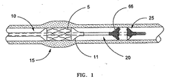
- deployment of balloon expandable stent 5 is accomplished by threading catheter 10 through the vascular system of the patient until stent 5 is located within a stenosis at predetermined treatment site 15. Once positioned, balloon 11 of catheter 10 is inflated to expand stent 5 against the vascular wall to maintain the opening. Stent deployment can be performed following treatments such as angioplasty, or during initial balloon dilation of the treatment site, which is referred to as primary stenting.
- Catheter 10 is typically guided to treatment site 15 by a guidewire.
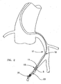
- a guidewire In cases where the target stenosis is located in tortuous vessels that are remote from the vascular access point, such as coronary arteries 17 shown in FIG. 2, a steerable guidewire is commonly used.
- filter guidewire generally designated as 20 guides catheter 10 to treatment site 15 and includes distally disposed filter 25 to collect embolic debris that may be generated during the procedure.
- the invention is directed to manipulating various types of temporary filters wherein relative movement of the filter ends either causes or accompanies transformation of the filter between a collapsed configuration and a deployed configuration. Such transformation may be impelled by external mechanical means or by self-shaping memory (either self-expanding or self-collapsing) within the filter.
- filter 25 is self-expanding, meaning that filter 25 has a mechanical memory to return to the expanded, or deployed configuration.
- Such mechanical memory can be imparted to the metal comprising filter 25 by thermal treatment to achieve a spring temper in stainless steel, for example, or to set a shape memory in a susceptible metal alloy such as nitinol.
- Filter 25 preferably comprises a tube formed by braided filaments that define pores and have at least one inlet opening 66 that is substantially larger than the pores.
- filters may be used in filter 25, such as filter assemblies that include a porous mesh mounted to expandable struts.
- At least one of the filaments maybe a wire having enhanced radiopacity compared to conventional non-radiopaque wires suitable for braiding filter 25.
- At least the majority of braiding wires forming filter 25 should be capable of being heat set into the desired filter shape, and such wires should also have sufficient elastic properties to provide the desired self-expanding or self-collapsing features.
- Stainless steel, and preferably nitinol monofilaments are suitable for braiding filter 25.
- a braiding wire having enhanced radiopacity may be made of, or coated with, a radiopaque metal such as gold, platinum, tungsten, alloys thereof, or other biocompatible metals having a relatively high X-ray attenuation coefficient compared with stainless steel or nitinol.
- a radiopaque metal such as gold, platinum, tungsten, alloys thereof, or other biocompatible metals having a relatively high X-ray attenuation coefficient compared with stainless steel or nitinol.
- One or more filaments having enhanced radiopacity may be inter-woven with non-radiopaque wires, or all wires comprising filter 25 may have the same enhanced radiopacity.
- sheathless vascular filter devices are operated by a "push-pull" mechanism that is also typical of other expandable braid devices, as shown in FIGS. 3 and 4.
- Prior art expandable braid device 30 includes core wire 32 and tubular shaft 34 slidably disposed thereabout.
- Tubular braid 36 surrounds core wire 32 and has a braid distal end fixed to core wire distal end 40 and a braid proximal end fixed to shaft distal end 41.
- core wire 32 is pulled and shaft 34 is pushed, as shown by arrows 37 and 39 respectively in FIG. 4.
- the relative displacement of core wire 32 and shaft 34 moves the ends of braid 36 towards each other, forcing the middle region of braid 36 to expand.
- core wire 32 is pushed and shaft 34 is pulled, as shown by arrows 33 and 35 respectively in FIG. 3. This reverse manipulation draws the ends of braid 36 apart, pulling the middle region of braid 36 radially inward toward core wire 32.
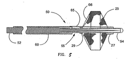
- FIG. 5 illustrates a first embodiment of the invention in which filter guidewire 50 also incorporates steerable guidewire 55.
- filter guidewire 50 the mounting arrangement of filter 25 is reversed with respect to filter guidewire 20, such that filter distal end 27 is slidably mounted around and adjacent to the distal end of guidewire 55, and filter proximal end 29 is fixed to guidewire 55.
- Elongate tubular actuator 60 is slidingly and coaxially disposed around guidewire 55 proximal to filter 25.
- Link 65 movably extends through opening 66 in filter 25 adjacent filter proximal end 29 and connects the distal end of actuator 60 to filter distal end 27. Opening 66 is one of the inlet openings of filter 25, however any opening large enough to slidably pass link 65 will suffice.
- a standard or over-sized pore in filter 25 may permit link 65 to extend therethrough.
- Actuator 60 can be made from thin walled metal tubing, such as stainless steel hypodermic tubing, or more preferably, polyimide tubing.
- actuator 60 should have an outside diameter of 0.014 inch (0.36 mm) or less so that filter guidewire 50 can be slidably received within the guidewire lumen of the catheter.
- Link 65 is preferably a thin wire, such as stainless steel, measuring approximately 0.002 to 0.008 inch (0.05 to 0.20 mm) in diameter, most preferably 0.006 inch (0.15 mm).
- link 65 may be a non-metallic filament capable of pushing and/or pulling filter distal end 27.
- Transformation of filter 25 from the deployed configuration to the collapsed configuration, shown in FIG. 8, is achieved by manipulating the proximal ends of guidewire 55 and actuator 60 as follows. Pushing actuator 60 distally while pulling guidewire 55 proximally causes link 65 to advance into filter 25 and displace filter distal end 27 distally along guidewire 55. The movement of filter distal end 27 away from filter proximal end 29, which is fixed to guidewire 55, forces filter 25 to collapse around guidewire 55 to a lower profile that is suitable for introduction to or withdrawal from the patient. The distal end of actuator 60 is spaced proximally from filter proximal end 29 a distance sufficient to permit a range of motion of actuator 60 without contacting filter proximal end 29. In this first version of the third embodiment of the invention, wherein filter 25 is self-expanding, link 65 is placed under compression loading to collapse filter 25, and thus link 65 is also referred to as a push rod.
- filter 25 may be self-collapsing, wherein its shape memory is to return to the collapsed configuration.
- deployment of filter 25 is achieved and maintained by pulling actuator 60 proximally while pushing guidewire 55 distally, which action draws filter distal end 27 and filter proximal end 29 towards each other and forces expansion of filter 25.
- link 65 is placed under tension loading to deploy filter 25.
- FIG. 6 depicts filter guidewire 56, which is a preferred second embodiment of the invention, and wherein self-expanding filter 25 is arranged over guidewire 55 similarly to filter guidewire 50, described above.
- actuator 62 is a short ring slidingly and coaxially disposed around guidewire 55 proximal to filter 25.
- Link 70 movably extends through opening 78 within filter proximal end 29 and connects actuator 62 to filter distal end 27.
- Link 70 includes link proximal segment 72 and link distal segment 74.
- Link distal segment 74 is a tubular element that is fixed to filter distal end 27 and is slidingly disposed around guidewire 55 within filter 25.
- Link distal segment 74 is made from thin walled tubing, preferably polyimide.
- Link proximal segment 72 is comparable to the wire of link 65, and extends from an attachment point on actuator 62 into filter 25 to connect with link distal segment 74.
- Joint 76 attaches filter proximal end 29 to guidewire 55, and includes opening 78, which guides link proximal segment 72 that is slidably disposed therethrough.
- Joint 76 may be made from any suitable fastening material such as adhesive, braze alloy, or preferably, solder.
- opening 78 is formed by a short section of thin walled polyimide tubing (not shown), which is incorporated into joint 76 within filter proximal end 29.
- opening 78 can be formed by including a removable mandrel, such as a stainless steel wire coated with polytetrafluoroethylene (PTFE), in joint 76 during its formation.
- PTFE polytetrafluoroethylene
- Elongate hollow rod 180 is slidably and removably disposed along guidewire 55 such that rod distal end 182 is engageable with actuator 62.
- Rod distal end 182 is an over-sized section of rod 180 such that it will slidably fit over at least a proximal portion of actuator 62, as shown in the alternate position in FIG. 6.
- the engaged combination of rod 180 and actuator 62 can apply distally directed force to link 70, similarly to the operation of elongate actuator 60 in guidewire filter 50.
- pushing rod 180 distally while pulling guidewire 55 proximally causes link 70 to advance into filter 25 and translate filter distal end 27 along guidewire 55 in a distal direction.
- filter distal end 27 forces filter 25 to collapse around guidewire 55 to a lower profile for introduction to or withdrawal from the patient.
- Actuator 62 is spaced proximally from filter proximal end 29 a distance sufficient to permit a range of motion of actuator 62 without contacting filter proximal end 29.
- rod distal end 182 can be an unexpanded end of rod 180, similar to rod distal end 82 of rod 80, in which case rod distal end 182 may simply abut actuator 62 without extending thereover.
- Optional stop 79 may be fixed to guidewire 55 proximal to actuator 62. Stop 79 can prevent interventional catheters positioned on guidewire 55 from engaging and moving actuator 62 and unintentionally collapsing filter 25. Stop 79 is smaller in diameter than actuator 62 such that rod 180 may be sized to slide over stop 79 and engage actuator 62, as shown in the alternate position in FIG. 12.
- filter guidewire 56 There are advantages to filter guidewire 56, besides the more habitual "reverse" push-pull action that it shares with filter guidewire 50, described above.
- guidewire 55 In filter guidewire 50, guidewire 55 must be small enough to fit slidably inside of actuator 60 which, in turn, must fit inside the guidewire lumen of a therapeutic catheter.
- guidewire 55 In filter guidewire 56, guidewire 55 can be large enough to fill the guidewire lumen of the same sized therapeutic catheter, because elongate rod 180 can be removed and replaced with the catheter.
- a larger, more standard sized guidewire can be included in the filter device, with the attendant performance advantages that accompany such an increase in size.
- FIG. 6 shows catheter 10 placed over filter guidewire 56, with optional stop 79 omitted therefrom.
- FIG. 8 shows the same arrangement as FIG. 7, with catheter 10 being advanced to operate actuator 62, causing filter 25 to collapse. As shown in FIG. 8, balloon 11 of catheter 10 would typically be deflated while catheter 10 is used to collapse filter 25.
- FIG. 9 depicts filter guidewire 85, which is a modification of filter guidewires 50, 56, and is made by mounting proximal assist spring 87 around guidewire 55 between filter proximal end 29 and actuators 60, 62.
- a modification of filter guidewire 56, filter 25 is self-expanding, and spring 87 is a coiled compression spring that assists in the expansion of filter 25 by maintaining a separating force between filter proximal end 29 and actuator 62.
- Spring 87 can surround guidewire 55 only or, preferably, surround both guidewire 55 and link 65,70, as shown.
- filter 25 is self-collapsing, with spring 87 being a coiled tension spring attached at its ends to filter proximal end 29 and actuator 60.
- actuator 60 can apply proximally directed force to overcome the shape memory of filter 25 and the tension force in spring 87.
- FIG. 10 depicts filter guidewire 89, which is another modification to filter guidewires 50, 56, and is made by mounting assist spring 91 around guidewire 55 distal to filter 25.
- filter 25 is self-expanding, with spring 91being a coiled compression spring having a proximal end abutting filter distal end 27 and having a distal end fixed to guidewire 55.
- Spring 91 assists in the deployment of filter 25 by maintaining proximally directed force against filter distal end 27.
- filter 25 is self-collapsing, with spring 91 being a tension spring having a proximal end fixed to filter distal end 27 and having a distal end fixed to guidewire 55.
- actuator 60 can apply proximally directed force to overcome the shape memory of filter 25 and the tension force in spring 91.
- FIG. 11 depicts filter guidewire 93, which is another modification to filter guidewires 50, 56, and is made by mounting assist spring 95 around guidewire 55 and link distal segment 74 inside filter 25.
- filter 25 is self-expanding, with spring 95 being a coiled tension spring having a distal end attached to filter distal end 27 and having a proximal end attached to filter proximal end 29.
- Spring 95 assists in the deployment of filter 25 by maintaining tension between filter distal and proximal ends 27, 29.
- filter 25 is self-collapsing, with spring 95 being a coiled compression spring mounted between filter distal and proximal ends 27, 29.
- actuator 60 can apply proximally directed force to overcome the shape memory of filter 25 and the compression force in spring 95.
- All of the above-mentioned coiled assist springs can be fabricated with fine metal wire of about 0.001 to 0.005 inch (0.03 to 0.13 mm) diameter, preferably nitinol wire having 0.003 inch (0.08 mm) diameter.
- a removable handle device (not shown) of a type familiar to those of skill in the art may be used.
- Such handle devices can have telescoping shafts with collet-type clamps that grip respectively, core wire 42 and shaft 44 in filter guidewire 20, guidewire 55 and actuator 60 in filter guidewire 50, and guidewire 55 and rods 80, 180 in filter guidewires 51 and 56.
- the handle device can also serve as a steering handle, or "torquer" which is useful for rotating steerable-type guidewires that are incorporated in the instant invention.
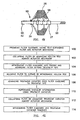
- filter guidewire 85 having self-expanding filter 25 and actuator 62, is provided (step 100), and filter 25 is collapsed by advancing hollow rod 180 against actuator 62 (step 102). With filter 25 in the collapsed configuration, filter guidewire 85 is advanced into the patient's vasculature until filter 25 is beyond the intended treatment site (step 104). Withdrawal of rod 180 allows filter 25 to expand under the combination of its own shape memory and the compression force of proximal spring 87 (step 106).
- a therapeutic catheter is advanced over filter guidewire 85 to the intended treatment site (step 108), and the therapy, such as balloon angioplasty, is performed (step 110). Any embolic debris generated during the therapy is captured in filter 25.
- the therapeutic catheter is prepared for withdrawal, as by deflating the balloon, if so equipped, and the catheter is advanced against actuator 62 to cause filter 25 to collapse (step 112).
- the catheter is used to continuously apply distally directed force against actuator 62 to maintain filter 25 in its collapsed configuration, filter guidewire 85 and the therapeutic catheter can be withdrawn together (step 114).
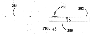
- FIG. 13 depicts a rapidly exchangeable rod 280 for use with filter guidewire 56.
- Rod 280 includes proximal shaft 284, and distal section 286, which is essentially a short portion of rod 180.
- Distal section 286 is only about 10 - 30 cm (3.9 - 11.8 inches) long, making it easy to exchange over the portion of filter guidewire 56 that extends outside of the patient, as is understood by those of skill in the field of intravascular catheters.
- Proximal shaft 284 preferably is a wire having a minimum diameter of about 0.012 inch (0.30 mm), and is tapered and attached to distal section 286.
- proximal shaft 284, and the secure attachment thereof to distal section 286 provide a rapidly exchangeable alternative to rod 180 for pushing or pulling actions, as may be required.
- catheter 10 can also be of the rapid exchange type to facilitate interchanging rods and catheters.
- the invention has been particularly shown and described with reference to the preferred embodiments thereof, it will be understood by those skilled in the art that various changes in form and detail may be made therein.
- the invention may be used in any intravascular treatment utilizing a guidewire where the possibility of loosening emboli may occur.
- the description herein illustrates angioplasty and stent placement procedures as significant applications, it should be understood that the present invention is in no way limited to those environments.
Abstract
Description
- The present invention relates generally to intraluminal devices for capturing particulate in the vessels of a patient. More particularly, the invention relates to a filter for capturing emboli in a blood vessel during an interventional vascular procedure and then removing the captured emboli from the patient after completion of the procedure. Furthermore, the invention concerns a filter mounted on a guidewire that can also be used to direct an interventional catheter to a treatment site within a patient.
- A variety of treatments exists for dilating or removing atherosclerotic plaque in blood vessels. The use of an angioplasty balloon catheter is common in the art as a minimally invasive treatment to enlarge a stenotic or diseased blood vessel. When applied to the vessels of the heart, this treatment is known as percutaneous transluminal coronary angioplasty, or PTCA. To provide radial support to the treated vessel in order to prolong the positive effects of PTCA, a stent may be implanted in conjunction with the procedure.
- Thrombectomy is a minimally invasive technique for removal of an entire thrombosis or a sufficient portion of the thrombosis to enlarge the stenotic or diseased blood vessel and may be accomplished instead of a PTCA procedure. Atherectomy is another well known minimally invasive procedure that mechanically cuts or abrades a stenosis within the diseased portion of the vessel. Alternatively, ablation therapies use laser or RF signals to superheat or vaporize the thrombus within the vessel. Emboli loosened during such procedures may be removed from the patient through the catheter.
- During each of these procedures, there is a risk that emboli dislodged by the procedure will migrate through the circulatory system and cause infarction or strokes. Thus, practitioners have approached prevention of escaped emboli through use of occlusion devices, filters, lysing and aspiration techniques. For example, it is known to remove the embolic material by suction through an aspiration lumen in the treatment catheter or by capturing emboli in a filter or occlusion device positioned distal of the treatment area.
- Prior art temporary filters or occlusion devices are associated with either a catheter or guidewire and are positioned downstream of the area to be treated. One prior art filter arrangement includes a dilatation balloon and a filter mounted on the same catheter. The filter is located distal to the dilatation balloon and consists of a filter material secured to resilient ribs. A filter balloon is located between the catheter exterior and the ribs. Inflation of the filter balloon extends the ribs outward across the vessel to form a trap for fragments loosened by the dilatation balloon. When the filter balloon is deflated, the resilient ribs retract against the catheter to retain the fragments during withdrawal of the catheter.
- Another prior art device includes a filter mounted on the distal portion of a hollow guidewire or tube. A moveable core wire is used to open and close the filter. The filter is secured at the proximal end to the tube and at the distal end to the core wire. Pulling on the core wire while pushing on the tube draws the ends of the filter toward each other, causing the filter framework between the ends to expand outward into contact with the vessel wall. Filter mesh material is mounted to the filter framework. To collapse the filter, the procedure is reversed; pulling on the tube while pushing on the core wire to draw the filter ends apart.
- Another prior art device has a filter made from a shape memory material. The device is deployed by moving the proximal end of the filter towards the distal end. It is collapsed and withdrawn by sliding a sheath over the filter and then removing the sheath and filter together.
- A further prior art filter device discloses a compressible polymeric foam filter mounted on a shaft that is inserted over a guidewire. The filter is inserted collapsed within a housing which is removed to deploy the filter once in position. The filter is retracted by inserting a large bore catheter over the shaft and the filter, and then removing the shaft, filter and catheter together.
- Another prior art filter arrangement has a filter comprised of a distal filter material secured to a proximal framework. This filter is deployed in an umbrella manner with a proximal member sliding along the shaft distally to open the filter and proximally to retract the filter. A large separate filter sheath can be slid onto the shaft and the filter is withdrawn into the sheath for removal from the patient.
- Other known prior art filters are secured to the distal end of a guidewire with a tubular shaft. Stoppers are placed on the guidewire proximal and distal of the filter, allowing the filter to move axially independently of the guidewire. A sheath is used to deploy and compress the filter.
- However, the guidewire-based filter devices do not have the handling characteristics expected of steerable guidewires. Abrupt transitions in stiffness in the area of the filter can limit the ability of the guidewire to negotiate tortuous vascular anatomy. Such device limitations can restrict the number of patients receiving the benefits of filtration during interventional vascular procedures. Filter guidewires that use a moveable core wire to actuate the filter also have diminished performance characteristics.
- Another problem associated with prior art filter guidewires is the requirement for a sheath to envelop and collapse the filter before and after the treatment is performed. Sheaths that encase the filter often require large bores, with attendant bulky handling. It is time-consuming and cumbersome to exchange the sheath for the treatment catheter and to reverse this exchange step at the end of the procedure.
- Another problem associated with self-expanding temporary filters is visualization of the filter under fluoroscopy. Filter braiding materials having good mechanical properties are not also very radiopaque to X-rays typically used during clinical procedures. Solutions to this problem typically require the addition of radiopaque material to the braiding wires, which often diminishes their shape-memory or elastic properties, or both.
- A filter according to the preamble of
claim 1 is shown in document WO 9923976 A1. - With the above in mind, it is an object of the present invention to provide a filter guidewire with improved handling characteristics.
- Another object of the present invention is to provide a filter guidewire that does not require an enveloping sheath to collapse the filter for insertion or withdrawal.
- The present invention is a temporary filter guidewire for use in intraluminal procedures. The device includes a filter assembly mounted adjacent the distal end of a guidewire used in the procedure. The filter is a tubular assembly that expands in the middle region when the ends are drawn toward each other. The filter assembly includes an expandable frame with a distal portion acting as the emboli filter. The emboli filter is sized sufficiently to expand and cover the lumen of the vessel distal to the intended treatment area.
- One embodiment of the invention is built around a standard-type steerable guidewire, which includes an elongate shaft having a distal region surrounded by a flexible tubular element, such as a coiled spring.
- A tubular filter assembly is mounted adjacent the distal end of the standard-type steerable guidewire. The distal end of the filter is slidably mounted to the guidewire, and the proximal end is fixed thereto. An actuator mechanism includes a link element slidably extending through the proximal end of the filter to provide a mechanical connection between the distal end of the filter and a proximal tubular control element. In this embodiment of the invention, the actuator mechanism reverses the push-pull action used for transforming the filter between collapsed and deployed configurations in the prior art and in the first and second embodiments of the invention. In this embodiment, pulling on the guidewire and pushing on the tubular control element causes the filter to be collapsed, rather than deployed.
- In the aforementioned embodiment of the invention, the actuator is slidably mounted over the guidewire and can be either an elongate hollow rod or a short ring. In the embodiment having the elongate rod, the rod can be manipulated directly from the proximal end of the device. In the embodiment having a short ring, the ring is operable by a removable hollow rod or tube, which may comprise a therapeutic catheter.
- To provide a temporary filter with enhanced radiopacity, but with undiminished physical performance, radiopaque material is added to one or more braiding wires, in the centers thereof, where the effect on physical properties of the wires is minimized.
-
- FIG. 1 is an illustration of a filter system in accordance with the invention deployed within a blood vessel;
- FIG. 2 is an illustration of a filter system in accordance with the invention deployed within a portion of the coronary arterial anatomy;
- FIG. 3 is an illustration of a prior art expandable mesh device, shown with the mesh in a collapsed configuration;
- FIG. 4 is an illustration of a prior art expandable mesh device, shown with the mesh in a deployed configuration;
- FIG. 5 is a longitudinal sectional view of a first guidewire filter embodiment in accordance with the invention;
- FIG. 6 is a longitudinal sectional view of a second guidewire filter embodiment in accordance with the invention, including a hollow rod slidably positioned thereon;
- FIG. 7 is a longitudinal view of the second guidewire filter system embodiment in accordance with the invention, including a balloon catheter slidably positioned thereon, shown with the filter in a deployed configuration;
- FIG. 8 is a longitudinal view of the second guidewire filter system embodiment in accordance with the invention, including a balloon catheter slidably positioned thereon, shown with the filter in a collapsed configuration;
- FIG. 9 is a side view taken of the distal portion of another guidewire filter system in accordance with the invention, showing a proximal assist spring;
- FIG. 10 is a side view taken of the distal portion of another guidewire filter system in accordance with the invention, showing a distal assist spring;
- FIG. 11 is a partial longitudinal sectional view taken of the distal portion of another guidewire filter system in accordance with the invention, showing an assist spring inside the filter;
- FIG. 12 is a flow chart depicting a method of using the guidewire filter system of the present invention;
- FIG. 13 is a side view of an alternative embodiment of a hollow rod for actuating a guidewire filter in accordance with the second embodiment of the invention.
- The present invention is a temporary filter guidewire for use in minimally invasive procedures, such as vascular interventions or other procedures where the practitioner desires to capture embolic material that may be dislodged during the procedure. Intravascular procedures such as PTCA or stent deployment are often preferable to more invasive surgical techniques in the treatment of vascular narrowings, called stenoses or lesions. With reference to FIG. 1 and FIG. 2, deployment of balloon
expandable stent 5 is accomplished by threadingcatheter 10 through the vascular system of the patient untilstent 5 is located within a stenosis atpredetermined treatment site 15. Once positioned,balloon 11 ofcatheter 10 is inflated to expandstent 5 against the vascular wall to maintain the opening. Stent deployment can be performed following treatments such as angioplasty, or during initial balloon dilation of the treatment site, which is referred to as primary stenting. -
Catheter 10 is typically guided totreatment site 15 by a guidewire. In cases where the target stenosis is located in tortuous vessels that are remote from the vascular access point, such ascoronary arteries 17 shown in FIG. 2, a steerable guidewire is commonly used. - According to the present invention, filter guidewire generally designated as 20
guides catheter 10 totreatment site 15 and includes distally disposedfilter 25 to collect embolic debris that may be generated during the procedure. The invention is directed to manipulating various types of temporary filters wherein relative movement of the filter ends either causes or accompanies transformation of the filter between a collapsed configuration and a deployed configuration. Such transformation may be impelled by external mechanical means or by self-shaping memory (either self-expanding or self-collapsing) within the filter. Preferably, filter 25 is self-expanding, meaning thatfilter 25 has a mechanical memory to return to the expanded, or deployed configuration. Such mechanical memory can be imparted to themetal comprising filter 25 by thermal treatment to achieve a spring temper in stainless steel, for example, or to set a shape memory in a susceptible metal alloy such as nitinol.Filter 25 preferably comprises a tube formed by braided filaments that define pores and have at least oneinlet opening 66 that is substantially larger than the pores. Alternative types of filters may be used infilter 25, such as filter assemblies that include a porous mesh mounted to expandable struts. - Optionally, adding radiopaque markers (not shown) to filter ends 27, 29 can aid in fluoroscopic observation of
filter 25 during manipulation thereof. Alternatively, to enhance visualization of braidedfilter 25 under fluoroscopy, at least one of the filaments maybe a wire having enhanced radiopacity compared to conventional non-radiopaque wires suitable for braidingfilter 25. At least the majority of braidingwires forming filter 25 should be capable of being heat set into the desired filter shape, and such wires should also have sufficient elastic properties to provide the desired self-expanding or self-collapsing features. Stainless steel, and preferably nitinol monofilaments are suitable for braidingfilter 25. A braiding wire having enhanced radiopacity may be made of, or coated with, a radiopaque metal such as gold, platinum, tungsten, alloys thereof, or other biocompatible metals having a relatively high X-ray attenuation coefficient compared with stainless steel or nitinol. One or more filaments having enhanced radiopacity may be inter-woven with non-radiopaque wires, or allwires comprising filter 25 may have the same enhanced radiopacity. - In accordance with the invention, maintaining
filter 25 in a collapsed configuration during introduction and withdrawal of filter guidewire 20 does not require a control sheath that slidingly envelopsfilter 25. Thus, this type of device is sometimes termed "sheathless." Known types of sheathless vascular filter devices are operated by a "push-pull" mechanism that is also typical of other expandable braid devices, as shown in FIGS. 3 and 4. Prior artexpandable braid device 30 includescore wire 32 andtubular shaft 34 slidably disposed thereabout.Tubular braid 36 surroundscore wire 32 and has a braid distal end fixed to core wiredistal end 40 and a braid proximal end fixed to shaftdistal end 41. To expandbraid 36,core wire 32 is pulled andshaft 34 is pushed, as shown byarrows core wire 32 andshaft 34 moves the ends ofbraid 36 towards each other, forcing the middle region ofbraid 36 to expand. To collapsebraid 36,core wire 32 is pushed andshaft 34 is pulled, as shown byarrows braid 36 apart, pulling the middle region ofbraid 36 radially inward towardcore wire 32. - FIG. 5 illustrates a first embodiment of the invention in which filter guidewire 50 also incorporates
steerable guidewire 55. Infilter guidewire 50, the mounting arrangement offilter 25 is reversed with respect to filterguidewire 20, such that filterdistal end 27 is slidably mounted around and adjacent to the distal end ofguidewire 55, and filterproximal end 29 is fixed toguidewire 55. Elongatetubular actuator 60 is slidingly and coaxially disposed aroundguidewire 55 proximal to filter 25.Link 65 movably extends through opening 66 infilter 25 adjacent filterproximal end 29 and connects the distal end ofactuator 60 to filterdistal end 27.Opening 66 is one of the inlet openings offilter 25, however any opening large enough to slidably passlink 65 will suffice. For example, a standard or over-sized pore infilter 25 may permitlink 65 to extend therethrough.Actuator 60 can be made from thin walled metal tubing, such as stainless steel hypodermic tubing, or more preferably, polyimide tubing. When an embodiment of filter guidewire 50 is designed and intended for use in clinical applications with small-lumen catheters, such as PTCA catheters, then actuator 60 should have an outside diameter of 0.014 inch (0.36 mm) or less so that filter guidewire 50 can be slidably received within the guidewire lumen of the catheter.Link 65 is preferably a thin wire, such as stainless steel, measuring approximately 0.002 to 0.008 inch (0.05 to 0.20 mm) in diameter, most preferably 0.006 inch (0.15 mm). Alternatively, link 65 may be a non-metallic filament capable of pushing and/or pulling filterdistal end 27. - Transformation of
filter 25 from the deployed configuration to the collapsed configuration, shown in FIG. 8, is achieved by manipulating the proximal ends ofguidewire 55 andactuator 60 as follows. Pushingactuator 60 distally while pullingguidewire 55 proximally causes link 65 to advance intofilter 25 and displace filterdistal end 27 distally alongguidewire 55. The movement of filterdistal end 27 away from filterproximal end 29, which is fixed to guidewire 55, forces filter 25 to collapse around guidewire 55 to a lower profile that is suitable for introduction to or withdrawal from the patient. The distal end ofactuator 60 is spaced proximally from filter proximal end 29 a distance sufficient to permit a range of motion ofactuator 60 without contacting filterproximal end 29. In this first version of the third embodiment of the invention, whereinfilter 25 is self-expanding, link 65 is placed under compression loading to collapsefilter 25, and thus link 65 is also referred to as a push rod. - Optionally, filter 25 may be self-collapsing, wherein its shape memory is to return to the collapsed configuration. In this second version of the first embodiment of the invention, deployment of
filter 25 is achieved and maintained by pullingactuator 60 proximally while pushingguidewire 55 distally, which action draws filterdistal end 27 and filterproximal end 29 towards each other and forces expansion offilter 25. In this embodiment, link 65 is placed under tension loading to deployfilter 25. - In the development of temporary guidewire filters, it has been determined that there may be practitioners who habitually tend to push the outer rod and pull the core wire when attempting to collapse the filter, which is contrary to the motion required in the conventional arrangements shown in FIGS. 3 and 4. Thus, the "reverse" push-pull action required in the self-expanding version of filter guidewire 50 is a more natural motion for a number of users.
- FIG. 6 depicts
filter guidewire 56, which is a preferred second embodiment of the invention, and wherein self-expandingfilter 25 is arranged overguidewire 55 similarly to filterguidewire 50, described above. Infilter guidewire 56,actuator 62 is a short ring slidingly and coaxially disposed aroundguidewire 55 proximal to filter 25.Link 70 movably extends through opening 78 within filterproximal end 29 and connectsactuator 62 to filterdistal end 27.Link 70 includes linkproximal segment 72 and linkdistal segment 74. Linkdistal segment 74 is a tubular element that is fixed to filterdistal end 27 and is slidingly disposed aroundguidewire 55 withinfilter 25. Linkdistal segment 74 is made from thin walled tubing, preferably polyimide. Linkproximal segment 72 is comparable to the wire oflink 65, and extends from an attachment point onactuator 62 intofilter 25 to connect with linkdistal segment 74. Joint 76 attaches filterproximal end 29 to guidewire 55, and includesopening 78, which guides linkproximal segment 72 that is slidably disposed therethrough. Joint 76 may be made from any suitable fastening material such as adhesive, braze alloy, or preferably, solder. Preferably, opening 78 is formed by a short section of thin walled polyimide tubing (not shown), which is incorporated into joint 76 within filterproximal end 29. Alternatively, opening 78 can be formed by including a removable mandrel, such as a stainless steel wire coated with polytetrafluoroethylene (PTFE), in joint 76 during its formation. The fastening material of joint 76 will not adhere to the mandrel, which can be removed to leaveopening 78. - Elongate
hollow rod 180 is slidably and removably disposed alongguidewire 55 such that roddistal end 182 is engageable withactuator 62. Roddistal end 182 is an over-sized section ofrod 180 such that it will slidably fit over at least a proximal portion ofactuator 62, as shown in the alternate position in FIG. 6. The engaged combination ofrod 180 andactuator 62 can apply distally directed force to link 70, similarly to the operation ofelongate actuator 60 inguidewire filter 50. Thus, pushingrod 180 distally while pullingguidewire 55 proximally causes link 70 to advance intofilter 25 and translate filterdistal end 27 alongguidewire 55 in a distal direction. The movement of filterdistal end 27 away from filterproximal end 29, which is fixed to guidewire 55, forces filter 25 to collapse around guidewire 55 to a lower profile for introduction to or withdrawal from the patient.Actuator 62 is spaced proximally from filter proximal end 29 a distance sufficient to permit a range of motion ofactuator 62 without contacting filterproximal end 29. Optionally, roddistal end 182 can be an unexpanded end ofrod 180, similar to rod distal end 82 of rod 80, in which case roddistal end 182 may simply abutactuator 62 without extending thereover. -
Optional stop 79, preferably a ring, may be fixed to guidewire 55 proximal toactuator 62.Stop 79 can prevent interventional catheters positioned onguidewire 55 from engaging and movingactuator 62 and unintentionally collapsingfilter 25.Stop 79 is smaller in diameter thanactuator 62 such thatrod 180 may be sized to slide overstop 79 and engageactuator 62, as shown in the alternate position in FIG. 12. - There are advantages to filter
guidewire 56, besides the more habitual "reverse" push-pull action that it shares withfilter guidewire 50, described above. Infilter guidewire 50, guidewire 55 must be small enough to fit slidably inside ofactuator 60 which, in turn, must fit inside the guidewire lumen of a therapeutic catheter. Infilter guidewire 56, guidewire 55 can be large enough to fill the guidewire lumen of the same sized therapeutic catheter, becauseelongate rod 180 can be removed and replaced with the catheter. Thus, a larger, more standard sized guidewire can be included in the filter device, with the attendant performance advantages that accompany such an increase in size. - As an alternative to the arrangement shown in FIG. 6, it may be desirable to use a catheter, such as
catheter 10, to operateactuators 63, 62 of guidewire filters 51, 56 respectively, to collapse self-expandingfilter 25. In such an arrangement,catheter 10 replacesrods 80, 180 in all respects, and no exchange is required therebetween. This simplified method of use can be performed during filter placement, during withdrawal, or both. FIG. 7 showscatheter 10 placed over filter guidewire 56, withoptional stop 79 omitted therefrom. FIG. 8 shows the same arrangement as FIG. 7, withcatheter 10 being advanced to operateactuator 62, causingfilter 25 to collapse. As shown in FIG. 8,balloon 11 ofcatheter 10 would typically be deflated whilecatheter 10 is used to collapsefilter 25. - FIG. 9 depicts filter guidewire 85, which is a modification of
filter guidewires proximal assist spring 87 aroundguidewire 55 between filterproximal end 29 andactuators filter 25 is self-expanding, andspring 87 is a coiled compression spring that assists in the expansion offilter 25 by maintaining a separating force between filterproximal end 29 andactuator 62.Spring 87 can surroundguidewire 55 only or, preferably, surround both guidewire 55 andlink filter 25 is self-collapsing, withspring 87 being a coiled tension spring attached at its ends to filterproximal end 29 andactuator 60. To deploy such a self-collapsing version offilter 25,actuator 60 can apply proximally directed force to overcome the shape memory offilter 25 and the tension force inspring 87. - FIG. 10 depicts
filter guidewire 89, which is another modification to filterguidewires assist spring 91 aroundguidewire 55 distal to filter 25. In the modification of filter guidewire 56,filter 25 is self-expanding, with spring 91being a coiled compression spring having a proximal end abutting filterdistal end 27 and having a distal end fixed toguidewire 55.Spring 91 assists in the deployment offilter 25 by maintaining proximally directed force against filterdistal end 27. Alternatively, in a modification of filter guidewire 50,filter 25 is self-collapsing, withspring 91 being a tension spring having a proximal end fixed to filterdistal end 27 and having a distal end fixed toguidewire 55. To deploy such a self-collapsing version offilter 25,actuator 60 can apply proximally directed force to overcome the shape memory offilter 25 and the tension force inspring 91. - FIG. 11 depicts
filter guidewire 93, which is another modification to filterguidewires assist spring 95 aroundguidewire 55 and linkdistal segment 74 insidefilter 25. In the modification of filter guidewire 56,filter 25 is self-expanding, withspring 95 being a coiled tension spring having a distal end attached to filterdistal end 27 and having a proximal end attached to filterproximal end 29.Spring 95 assists in the deployment offilter 25 by maintaining tension between filter distal and proximal ends 27, 29. Alternatively, in a modification of filter guidewire 50,filter 25 is self-collapsing, withspring 95 being a coiled compression spring mounted between filter distal and proximal ends 27, 29. To deploy such a self-collapsing version offilter 25,actuator 60 can apply proximally directed force to overcome the shape memory offilter 25 and the compression force inspring 95. All of the above-mentioned coiled assist springs can be fabricated with fine metal wire of about 0.001 to 0.005 inch (0.03 to 0.13 mm) diameter, preferably nitinol wire having 0.003 inch (0.08 mm) diameter. - To adjust and maintain the relative longitudinal and/or rotational positions of guidewires and the surrounding tubular elements in the various embodiments of the invention, a removable handle device (not shown) of a type familiar to those of skill in the art may be used. Such handle devices can have telescoping shafts with collet-type clamps that grip respectively, core wire 42 and shaft 44 in
filter guidewire 20, guidewire 55 andactuator 60 infilter guidewire 50, and guidewire 55 androds 80, 180 infilter guidewires 51 and 56. The handle device can also serve as a steering handle, or "torquer" which is useful for rotating steerable-type guidewires that are incorporated in the instant invention. - A method of using of the filter guidewires of the invention will be described below. Referring to FIG. 12, filter guidewire 85, having self-expanding
filter 25 andactuator 62, is provided (step 100), and filter 25 is collapsed by advancinghollow rod 180 against actuator 62 (step 102). Withfilter 25 in the collapsed configuration, filter guidewire 85 is advanced into the patient's vasculature untilfilter 25 is beyond the intended treatment site (step 104). Withdrawal ofrod 180 allowsfilter 25 to expand under the combination of its own shape memory and the compression force of proximal spring 87 (step 106). Withfilter 25 deployed into contact with the vessel wall, a therapeutic catheter is advanced over filter guidewire 85 to the intended treatment site (step 108), and the therapy, such as balloon angioplasty, is performed (step 110). Any embolic debris generated during the therapy is captured infilter 25. After the therapy is completed, the therapeutic catheter is prepared for withdrawal, as by deflating the balloon, if so equipped, and the catheter is advanced againstactuator 62 to causefilter 25 to collapse (step 112). Finally, while the catheter is used to continuously apply distally directed force againstactuator 62 to maintainfilter 25 in its collapsed configuration, filter guidewire 85 and the therapeutic catheter can be withdrawn together (step 114). Although the steps above describe usingrod 180 and the therapeutic catheter to introduce and withdraw filter guidewire 85, respectively, it should be understood that variations are possible, since any tubular device that can engage and operateactuator 62 can be used, either during introduction or withdrawal. -
Filter guidewires 56, as described above, utilizes removablehollow rod 180, to engage and manipulateactuator 62. FIG. 13 depicts a rapidlyexchangeable rod 280 for use withfilter guidewire 56.Rod 280 includesproximal shaft 284, anddistal section 286, which is essentially a short portion ofrod 180.Distal section 286 is only about 10 - 30 cm (3.9 - 11.8 inches) long, making it easy to exchange over the portion of filter guidewire 56 that extends outside of the patient, as is understood by those of skill in the field of intravascular catheters.Proximal shaft 284 preferably is a wire having a minimum diameter of about 0.012 inch (0.30 mm), and is tapered and attached todistal section 286. The stiffness ofproximal shaft 284, and the secure attachment thereof todistal section 286 provide a rapidly exchangeable alternative torod 180 for pushing or pulling actions, as may be required. It will be understood thatcatheter 10 can also be of the rapid exchange type to facilitate interchanging rods and catheters. - While the invention has been particularly shown and described with reference to the preferred embodiments thereof, it will be understood by those skilled in the art that various changes in form and detail may be made therein. For example, the invention may be used in any intravascular treatment utilizing a guidewire where the possibility of loosening emboli may occur. Although the description herein illustrates angioplasty and stent placement procedures as significant applications, it should be understood that the present invention is in no way limited to those environments.
Claims (17)
- A temporary filter device (50, 56, 85, 93) comprising:an elongate flexible guidewire (55) having a proximal end, a distal end, and a flexible tubular element (54) fixed about a guidewire distal region;a generally tubular filter (25) mounted coaxially about the guidewire (55);characterized in that
the filter (25) has a tapered distal end (27) slidingly disposed about the guidewire (55) and a tapered proximal end (29) fixed to the guidewire (55), the filter (25) including an opening (66, 78) adjacent the filter proximal end (29);
an actuator mechanism is slidably disposed about the guidewire (55) and extends slidably through the opening (66, 78) to connect with the filter distal end (27), wherein proximal displacement of the guidewire (55) relative to the actuator mechanism separates the filter proximal and distal ends, causing transformation of the filter (55) from a deployed configuration to a collapsed configuration. - The temporary filter device (50, 56, 85, 89, 93) of claim 1 wherein the actuator mechanism further comprises:a tubular actuator (60, 62) slidably disposed along the guidewire, the actuator including a proximal end and a distal end disposed proximally of the filter (55); anda link (65, 70) slidably disposed through the opening (66, 78) and connecting the actuator distal end to the filter distal end (27).
- The temporary filter device (56, 85, 89, 93) of claim 1 wherein the link (70) includes a tubular distal segment (74) slidably disposed along the guidewire (55), the distal segment (74) being disposed within the filter (25).
- The temporary filter device (50, 85, 89, 93) of claim 1 wherein the tubular actuator (60) is an elongate tube.
- The temporary filter device (56, 85, 89, 93) of claim 1 wherein the tubular actuator (62) is a relatively short tube or ring.
- The temporary filter device (56, 85, 89, 93) of claim 5 further comprising an elongate hollow rod (10, 180, 280) slidably and removably disposed along the guidewire (55), the rod (180, 280) having a distal end (182) engageable with the tubular actuator (62).
- The temporary filter device (56) of claim 6 further comprising a stop element (79) fixed to the guidewire (55) proximal to the tubular actuator (62), the stop element (79) having a transverse dimension smaller than a transverse dimension of the tubular actuator (62) such that the stop element (79) is operable to permit the hollow rod (180) to slide there over while being capable of preventing a catheter (10) slidably mounted on the guidewire (55) from engaging the tubular actuator (62).
- The temporary filter device (56, 85, 89, 93) of claim 6 wherein the hollow rod (280) comprises an elongate, wire-like proximal shaft (284) and a relatively short tubular distal section (286).
- The temporary filter device (56, 85, 89, 93) of claim 6 wherein the elongate hollow rod (10) further comprises an interventional catheter (10).
- The temporary filter device (85) of any of the preceding claims further comprising a coiled compression spring (87) disposed around the guidewire between and abutting the filter proximal end (29) and the actuator (60, 62) distal end to assist in transformation of the filter (25) to the deployed configuration.
- The temporary filter device (85) of any one of the preceding claims further comprising a coiled tension spring (95) disposed around the guidewire (55), the tension spring (95) attached between the filter proximal and distal ends (29, 27) to assist in transformation of the filter (25) to the deployed configuration.
- The temporary filter device (89) of any of the preceding claims further comprising a coiled compression spring (91) disposed around the guidewire (55), the compression spring (91) having a spring distal end fixed to the guidewire (55) about the guidewire distal region and a spring proximal end abutting the filter distal end (27) to assist in transformation of the filter (25) to the deployed configuration.
- The temporary filter device (85) of any of claims 1-9 further comprising a coiled tension spring (87) disposed around the guidewire (55), the tension spring (87) attached between the filter proximal end (29) and the actuator distal end (60, 62) to assist in transformation of the filter to the collapsed configuration.
- The temporary filter device (93) of any of claims 1-9 further comprising a coiled compression spring (95) disposed around the guidewire (55) between and abutting the filter proximal and distal ends (29, 27) to assist in transformation of the filter (25) to the collapsed configuration.
- The temporary filter device (89) of any of claims 1-9 further comprising a coiled tension spring (91) disposed around the guidewire (55), the tension spring (91) having a spring distal end fixed to the guidewire (55) about the guidewire distal region and a spring proximal end fixed to the filter distal end (27) to assist in transformation of the filter (25) to the collapsed configuration.
- The temporary filter device (56, 85, 89, 93) of any of the above claims wherein the proximal end (29) of the filter (25) is fixed about the guidewire (55) by a joint (76) having the opening (78) there through.
- The temporary filter device (50, 56, 85, 89, 93) of any of the above claims wherein the generally tubular filter (25) is a braided tubular filter (25).
Applications Claiming Priority (3)
| Application Number | Priority Date | Filing Date | Title |
|---|---|---|---|
| US09/824,832 US6866677B2 (en) | 2001-04-03 | 2001-04-03 | Temporary intraluminal filter guidewire and methods of use |
| US824832 | 2001-04-03 | ||
| EP02003917A EP1247500B1 (en) | 2001-04-03 | 2002-02-21 | Temporary intraluminal filter guidewire and methods of use |
Related Parent Applications (1)
| Application Number | Title | Priority Date | Filing Date |
|---|---|---|---|
| EP02003917A Division EP1247500B1 (en) | 2001-04-03 | 2002-02-21 | Temporary intraluminal filter guidewire and methods of use |
Publications (2)
| Publication Number | Publication Date |
|---|---|
| EP1371344A1 EP1371344A1 (en) | 2003-12-17 |
| EP1371344B1 true EP1371344B1 (en) | 2006-11-15 |
Family
ID=25242438
Family Applications (3)
| Application Number | Title | Priority Date | Filing Date |
|---|---|---|---|
| EP03016924A Expired - Lifetime EP1371344B1 (en) | 2001-04-03 | 2002-02-21 | Temporary intraluminal filter device |
| EP02003917A Expired - Lifetime EP1247500B1 (en) | 2001-04-03 | 2002-02-21 | Temporary intraluminal filter guidewire and methods of use |
| EP03016923A Expired - Lifetime EP1369096B1 (en) | 2001-04-03 | 2002-02-21 | Temporary intraluminal filter |
Family Applications After (2)
| Application Number | Title | Priority Date | Filing Date |
|---|---|---|---|
| EP02003917A Expired - Lifetime EP1247500B1 (en) | 2001-04-03 | 2002-02-21 | Temporary intraluminal filter guidewire and methods of use |
| EP03016923A Expired - Lifetime EP1369096B1 (en) | 2001-04-03 | 2002-02-21 | Temporary intraluminal filter |
Country Status (5)
| Country | Link |
|---|---|
| US (2) | US6866677B2 (en) |
| EP (3) | EP1371344B1 (en) |
| JP (1) | JP2002336261A (en) |
| AT (3) | ATE345095T1 (en) |
| DE (3) | DE60205053T2 (en) |
Families Citing this family (197)
| Publication number | Priority date | Publication date | Assignee | Title |
|---|---|---|---|---|
| WO1998039053A1 (en) | 1997-03-06 | 1998-09-11 | Scimed Life Systems, Inc. | Distal protection device and method |
| US7491216B2 (en) | 1997-11-07 | 2009-02-17 | Salviac Limited | Filter element with retractable guidewire tip |
| EP1752112B1 (en) | 1997-11-07 | 2009-12-23 | Salviac Limited | An embolic protection device |
| US6964672B2 (en) | 1999-05-07 | 2005-11-15 | Salviac Limited | Support frame for an embolic protection device |
| US6918921B2 (en) | 1999-05-07 | 2005-07-19 | Salviac Limited | Support frame for an embolic protection device |
| US6575997B1 (en) | 1999-12-23 | 2003-06-10 | Endovascular Technologies, Inc. | Embolic basket |
| US6402771B1 (en) | 1999-12-23 | 2002-06-11 | Guidant Endovascular Solutions | Snare |
| US6660021B1 (en) | 1999-12-23 | 2003-12-09 | Advanced Cardiovascular Systems, Inc. | Intravascular device and system |
| US7918820B2 (en) | 1999-12-30 | 2011-04-05 | Advanced Cardiovascular Systems, Inc. | Device for, and method of, blocking emboli in vessels such as blood arteries |
| US6695813B1 (en) | 1999-12-30 | 2004-02-24 | Advanced Cardiovascular Systems, Inc. | Embolic protection devices |
| GB2369575A (en) * | 2000-04-20 | 2002-06-05 | Salviac Ltd | An embolic protection system |
| US6964670B1 (en) | 2000-07-13 | 2005-11-15 | Advanced Cardiovascular Systems, Inc. | Embolic protection guide wire |
| US6506203B1 (en) | 2000-12-19 | 2003-01-14 | Advanced Cardiovascular Systems, Inc. | Low profile sheathless embolic protection system |
| US20020188314A1 (en) * | 2001-06-07 | 2002-12-12 | Microvena Corporation | Radiopaque distal embolic protection device |
| US7338510B2 (en) | 2001-06-29 | 2008-03-04 | Advanced Cardiovascular Systems, Inc. | Variable thickness embolic filtering devices and method of manufacturing the same |
| US6599307B1 (en) | 2001-06-29 | 2003-07-29 | Advanced Cardiovascular Systems, Inc. | Filter device for embolic protection systems |
| US6962598B2 (en) * | 2001-07-02 | 2005-11-08 | Rubicon Medical, Inc. | Methods, systems, and devices for providing embolic protection |
| US6951570B2 (en) * | 2001-07-02 | 2005-10-04 | Rubicon Medical, Inc. | Methods, systems, and devices for deploying a filter from a filter device |
| US6638294B1 (en) | 2001-08-30 | 2003-10-28 | Advanced Cardiovascular Systems, Inc. | Self furling umbrella frame for carotid filter |
| US6592606B2 (en) | 2001-08-31 | 2003-07-15 | Advanced Cardiovascular Systems, Inc. | Hinged short cage for an embolic protection device |
| US6878151B2 (en) * | 2001-09-27 | 2005-04-12 | Scimed Life Systems, Inc. | Medical retrieval device |
| US8262689B2 (en) | 2001-09-28 | 2012-09-11 | Advanced Cardiovascular Systems, Inc. | Embolic filtering devices |
| US20050021075A1 (en) * | 2002-12-30 | 2005-01-27 | Bonnette Michael J. | Guidewire having deployable sheathless protective filter |
| US7241304B2 (en) | 2001-12-21 | 2007-07-10 | Advanced Cardiovascular Systems, Inc. | Flexible and conformable embolic filtering devices |
| AU2002351156A1 (en) | 2001-12-21 | 2003-07-15 | Salviac Limited | A support frame for an embolic protection device |
| US6773448B2 (en) | 2002-03-08 | 2004-08-10 | Ev3 Inc. | Distal protection devices having controllable wire motion |
| WO2003088869A2 (en) * | 2002-04-19 | 2003-10-30 | Salviac Limited | A medical device |
| US8070769B2 (en) | 2002-05-06 | 2011-12-06 | Boston Scientific Scimed, Inc. | Inverted embolic protection filter |
| US7232452B2 (en) | 2002-07-12 | 2007-06-19 | Ev3 Inc. | Device to create proximal stasis |
| WO2004012628A1 (en) * | 2002-08-05 | 2004-02-12 | Uri Rosenschein | Embolism filter with self-deployable guidewire stop |
| US7252675B2 (en) | 2002-09-30 | 2007-08-07 | Advanced Cardiovascular, Inc. | Embolic filtering devices |
| US7331973B2 (en) * | 2002-09-30 | 2008-02-19 | Avdanced Cardiovascular Systems, Inc. | Guide wire with embolic filtering attachment |
| US20040088000A1 (en) | 2002-10-31 | 2004-05-06 | Muller Paul F. | Single-wire expandable cages for embolic filtering devices |
| US7323001B2 (en) * | 2003-01-30 | 2008-01-29 | Ev3 Inc. | Embolic filters with controlled pore size |
| JP2004261235A (en) * | 2003-02-20 | 2004-09-24 | Kaneka Medix Corp | Medical wire device |
| US8591540B2 (en) | 2003-02-27 | 2013-11-26 | Abbott Cardiovascular Systems Inc. | Embolic filtering devices |
| US20040193208A1 (en) * | 2003-03-27 | 2004-09-30 | Scimed Life Systems, Inc. | Radiopaque embolic protection filter membrane |
| US7597704B2 (en) * | 2003-04-28 | 2009-10-06 | Atritech, Inc. | Left atrial appendage occlusion device with active expansion |
| EP1472995B1 (en) | 2003-04-30 | 2008-12-03 | Medtronic Vascular, Inc. | Perivascular leak repair system |
| US7892251B1 (en) | 2003-11-12 | 2011-02-22 | Advanced Cardiovascular Systems, Inc. | Component for delivering and locking a medical device to a guide wire |
| US7988705B2 (en) * | 2004-03-06 | 2011-08-02 | Lumen Biomedical, Inc. | Steerable device having a corewire within a tube and combination with a functional medical component |
| US7678129B1 (en) | 2004-03-19 | 2010-03-16 | Advanced Cardiovascular Systems, Inc. | Locking component for an embolic filter assembly |
| US20060206200A1 (en) | 2004-05-25 | 2006-09-14 | Chestnut Medical Technologies, Inc. | Flexible vascular occluding device |
| AU2005247490B2 (en) | 2004-05-25 | 2011-05-19 | Covidien Lp | Flexible vascular occluding device |
| US8617234B2 (en) | 2004-05-25 | 2013-12-31 | Covidien Lp | Flexible vascular occluding device |
| US8147534B2 (en) | 2005-05-25 | 2012-04-03 | Tyco Healthcare Group Lp | System and method for delivering and deploying an occluding device within a vessel |
| KR101300437B1 (en) | 2004-05-25 | 2013-08-26 | 코비디엔 엘피 | Vascular stenting for aneurysms |
| US8267985B2 (en) | 2005-05-25 | 2012-09-18 | Tyco Healthcare Group Lp | System and method for delivering and deploying an occluding device within a vessel |
| US8628564B2 (en) | 2004-05-25 | 2014-01-14 | Covidien Lp | Methods and apparatus for luminal stenting |
| US8795315B2 (en) | 2004-10-06 | 2014-08-05 | Cook Medical Technologies Llc | Emboli capturing device having a coil and method for capturing emboli |
| US9510930B2 (en) * | 2008-10-22 | 2016-12-06 | Contego Medical, Llc | Angioplasty device with embolic filter |
| US9707071B2 (en) * | 2004-11-24 | 2017-07-18 | Contego Medical Llc | Percutaneous transluminal angioplasty device with integral embolic filter |
| US8038696B2 (en) * | 2004-12-06 | 2011-10-18 | Boston Scientific Scimed, Inc. | Sheath for use with an embolic protection filter |
| US20060184194A1 (en) * | 2005-02-15 | 2006-08-17 | Cook Incorporated | Embolic protection device |
| US8221446B2 (en) | 2005-03-15 | 2012-07-17 | Cook Medical Technologies | Embolic protection device |
| US8945169B2 (en) | 2005-03-15 | 2015-02-03 | Cook Medical Technologies Llc | Embolic protection device |
| US9259305B2 (en) | 2005-03-31 | 2016-02-16 | Abbott Cardiovascular Systems Inc. | Guide wire locking mechanism for rapid exchange and other catheter systems |
| US20070233174A1 (en) * | 2005-04-01 | 2007-10-04 | Gordon Hocking | Trapping Filter for Blood Vessel |
| US20090118612A1 (en) | 2005-05-06 | 2009-05-07 | Sorin Grunwald | Apparatus and Method for Vascular Access |
| US8409103B2 (en) * | 2005-05-06 | 2013-04-02 | Vasonova, Inc. | Ultrasound methods of positioning guided vascular access devices in the venous system |
| US8273101B2 (en) * | 2005-05-25 | 2012-09-25 | Tyco Healthcare Group Lp | System and method for delivering and deploying an occluding device within a vessel |
| US8109962B2 (en) | 2005-06-20 | 2012-02-07 | Cook Medical Technologies Llc | Retrievable device having a reticulation portion with staggered struts |
| US7850708B2 (en) | 2005-06-20 | 2010-12-14 | Cook Incorporated | Embolic protection device having a reticulated body with staggered struts |
| US7766934B2 (en) | 2005-07-12 | 2010-08-03 | Cook Incorporated | Embolic protection device with an integral basket and bag |
| US7771452B2 (en) | 2005-07-12 | 2010-08-10 | Cook Incorporated | Embolic protection device with a filter bag that disengages from a basket |
| US8187298B2 (en) | 2005-08-04 | 2012-05-29 | Cook Medical Technologies Llc | Embolic protection device having inflatable frame |
| US8377092B2 (en) | 2005-09-16 | 2013-02-19 | Cook Medical Technologies Llc | Embolic protection device |
| US20070073332A1 (en) * | 2005-09-26 | 2007-03-29 | Medtronic Vascular, Inc. | Intraluminal filter having a cover sleeve |
| US8632562B2 (en) | 2005-10-03 | 2014-01-21 | Cook Medical Technologies Llc | Embolic protection device |
| US8182508B2 (en) | 2005-10-04 | 2012-05-22 | Cook Medical Technologies Llc | Embolic protection device |
| US7811251B2 (en) * | 2005-10-13 | 2010-10-12 | Tyco Healthcare Group Lp | Trocar anchor |
| US8252017B2 (en) | 2005-10-18 | 2012-08-28 | Cook Medical Technologies Llc | Invertible filter for embolic protection |
| US8216269B2 (en) | 2005-11-02 | 2012-07-10 | Cook Medical Technologies Llc | Embolic protection device having reduced profile |
| US20070112371A1 (en) * | 2005-11-14 | 2007-05-17 | Medtronic Vascular, Inc. | Embolic protection filter having compact collapsed dimensions and method of making same |
| US8152831B2 (en) | 2005-11-17 | 2012-04-10 | Cook Medical Technologies Llc | Foam embolic protection device |
| US20070135826A1 (en) * | 2005-12-01 | 2007-06-14 | Steve Zaver | Method and apparatus for delivering an implant without bias to a left atrial appendage |
| US20070149996A1 (en) * | 2005-12-28 | 2007-06-28 | Medtronic Vascular, Inc. | Low profile filter |
| US20070156168A1 (en) * | 2005-12-29 | 2007-07-05 | Medtronic Vascular, Inc. | Polymer marker and retention bands |
| US20070179519A1 (en) * | 2006-01-27 | 2007-08-02 | Wang Huisun | Stent delivery system to improve placement accuracy for self-expanding stent |
| WO2007089897A2 (en) | 2006-02-01 | 2007-08-09 | The Cleveland Clinic Foundation | Inflatable-deflatable passive exercise unit |
| US8152833B2 (en) | 2006-02-22 | 2012-04-10 | Tyco Healthcare Group Lp | Embolic protection systems having radiopaque filter mesh |
| US7846175B2 (en) * | 2006-04-03 | 2010-12-07 | Medrad, Inc. | Guidewire and collapsable filter system |
| DE102006024176B4 (en) * | 2006-05-23 | 2008-08-28 | Pah, Gunnar M. | A device for filtering blood in the removal of heart valve stenosis and methods for eliminating heart valve stenosis |
| US20080234722A1 (en) * | 2006-06-14 | 2008-09-25 | Possis Medical, Inc. | Inferior vena cava filter on guidewire |
| US8167902B2 (en) * | 2006-08-11 | 2012-05-01 | Tyco Healthcare Group Lp | Rapid exchange catheters for embolic protection devices |
| US20080045863A1 (en) * | 2006-08-17 | 2008-02-21 | Ethicon Endo-Surgery, Inc. | Guidewire structure including a medical guidewire |
| US8715205B2 (en) * | 2006-08-25 | 2014-05-06 | Cook Medical Tecnologies Llc | Loop tip wire guide |
| US20080071307A1 (en) | 2006-09-19 | 2008-03-20 | Cook Incorporated | Apparatus and methods for in situ embolic protection |
| US9901434B2 (en) | 2007-02-27 | 2018-02-27 | Cook Medical Technologies Llc | Embolic protection device including a Z-stent waist band |
| US9144509B2 (en) | 2007-05-31 | 2015-09-29 | Abbott Cardiovascular Systems Inc. | Method and apparatus for delivering an agent to a kidney |
| US9149610B2 (en) | 2007-05-31 | 2015-10-06 | Abbott Cardiovascular Systems Inc. | Method and apparatus for improving delivery of an agent to a kidney |
| US8216209B2 (en) | 2007-05-31 | 2012-07-10 | Abbott Cardiovascular Systems Inc. | Method and apparatus for delivering an agent to a kidney |
| US9364586B2 (en) | 2007-05-31 | 2016-06-14 | Abbott Cardiovascular Systems Inc. | Method and apparatus for improving delivery of an agent to a kidney |
| WO2009003138A1 (en) | 2007-06-26 | 2008-12-31 | Vasonova, Inc. | Apparatus and method for endovascular device guiding and positioning using physiological parameters |
| US7867273B2 (en) | 2007-06-27 | 2011-01-11 | Abbott Laboratories | Endoprostheses for peripheral arteries and other body vessels |
| US9138307B2 (en) | 2007-09-14 | 2015-09-22 | Cook Medical Technologies Llc | Expandable device for treatment of a stricture in a body vessel |
| US8419748B2 (en) | 2007-09-14 | 2013-04-16 | Cook Medical Technologies Llc | Helical thrombus removal device |
| US8252018B2 (en) | 2007-09-14 | 2012-08-28 | Cook Medical Technologies Llc | Helical embolic protection device |
| US20090099591A1 (en) | 2007-10-15 | 2009-04-16 | Boston Scientific Scimed, Inc. | Coil Anchor Systems and Methods of Use |
| US20090105746A1 (en) * | 2007-10-17 | 2009-04-23 | Gardia Medical Ltd | Guidewire stop |
| US7819844B2 (en) * | 2007-10-17 | 2010-10-26 | Gardia Medical Ltd. | Guidewire stop |
| US9675482B2 (en) | 2008-05-13 | 2017-06-13 | Covidien Lp | Braid implant delivery systems |
| US8070694B2 (en) | 2008-07-14 | 2011-12-06 | Medtronic Vascular, Inc. | Fiber based medical devices and aspiration catheters |
| JP5366497B2 (en) * | 2008-10-14 | 2013-12-11 | アクセスポイント テクノロジーズ有限会社 | Embolic material excision capture device |
| US8388644B2 (en) | 2008-12-29 | 2013-03-05 | Cook Medical Technologies Llc | Embolic protection device and method of use |
| JP5495587B2 (en) * | 2009-03-09 | 2014-05-21 | オリンパスメディカルシステムズ株式会社 | Medical equipment |
| US20100268029A1 (en) * | 2009-04-21 | 2010-10-21 | Xlumena, Inc. | Methods and apparatus for advancing a device from one body lumen to another |
| US8500775B2 (en) * | 2009-12-02 | 2013-08-06 | Surefire Medical, Inc. | Protection device and method against embolization agent reflux |
| US8696698B2 (en) | 2009-12-02 | 2014-04-15 | Surefire Medical, Inc. | Microvalve protection device and method of use for protection against embolization agent reflux |
| US9539081B2 (en) | 2009-12-02 | 2017-01-10 | Surefire Medical, Inc. | Method of operating a microvalve protection device |
| US9579193B2 (en) | 2010-09-23 | 2017-02-28 | Transmural Systems Llc | Methods and systems for delivering prostheses using rail techniques |
| US10321998B2 (en) | 2010-09-23 | 2019-06-18 | Transmural Systems Llc | Methods and systems for delivering prostheses using rail techniques |
| EP2637568B1 (en) | 2010-11-08 | 2017-04-12 | Vasonova, Inc. | Endovascular navigation system |
| US9770319B2 (en) | 2010-12-01 | 2017-09-26 | Surefire Medical, Inc. | Closed tip dynamic microvalve protection device |
| EP2739217B1 (en) | 2011-08-05 | 2022-07-20 | Route 92 Medical, Inc. | Systems for treatment of acute ischemic stroke |
| US9119639B2 (en) | 2011-08-09 | 2015-09-01 | DePuy Synthes Products, Inc. | Articulated cavity creator |
| US9549817B2 (en) | 2011-09-22 | 2017-01-24 | Transmural Systems Llc | Devices, systems and methods for repairing lumenal systems |
| US9089668B2 (en) | 2011-09-28 | 2015-07-28 | Surefire Medical, Inc. | Flow directional infusion device |
| BR112014012352A2 (en) * | 2011-11-10 | 2017-07-18 | Transaortic Medical Inc | system for implanting a device at a distal location through a diseased vessel |
| US9545298B2 (en) | 2011-11-10 | 2017-01-17 | Transaortic Medical, Inc. | System for deploying a device to a distal location across a diseased vessel |
| US11213318B2 (en) | 2011-11-10 | 2022-01-04 | Medtronic Vascular, Inc. | Expandable introducer sheath and method |
| WO2013119332A2 (en) | 2012-02-09 | 2013-08-15 | Stout Medical Group, L.P. | Embolic device and methods of use |
| US9089341B2 (en) | 2012-02-28 | 2015-07-28 | Surefire Medical, Inc. | Renal nerve neuromodulation device |
| JP2015513432A (en) * | 2012-03-09 | 2015-05-14 | キーストーン ハート リミテッド | Device and method for deflecting emboli in the aorta |
| EP2846686B1 (en) | 2012-05-07 | 2018-01-03 | Vasonova, Inc. | System for detection of the superior vena cava area and the cavoatrial junction |
| US9155647B2 (en) | 2012-07-18 | 2015-10-13 | Covidien Lp | Methods and apparatus for luminal stenting |
| US9301831B2 (en) | 2012-10-30 | 2016-04-05 | Covidien Lp | Methods for attaining a predetermined porosity of a vascular device |
| US9452070B2 (en) | 2012-10-31 | 2016-09-27 | Covidien Lp | Methods and systems for increasing a density of a region of a vascular device |
| US9943427B2 (en) | 2012-11-06 | 2018-04-17 | Covidien Lp | Shaped occluding devices and methods of using the same |
| US9241729B2 (en) | 2012-12-14 | 2016-01-26 | DePuy Synthes Products, Inc. | Device to aid in the deployment of a shape memory instrument |
| US9439693B2 (en) | 2013-02-01 | 2016-09-13 | DePuy Synthes Products, Inc. | Steerable needle assembly for use in vertebral body augmentation |
| US9157174B2 (en) | 2013-02-05 | 2015-10-13 | Covidien Lp | Vascular device for aneurysm treatment and providing blood flow into a perforator vessel |
| JP2013154183A (en) * | 2013-03-12 | 2013-08-15 | Contego Medical Llc | Percutaneous intravascular blood vessel formation device having integrated embolic filter |
| CN105377184B (en) | 2013-03-15 | 2017-06-30 | 微仙美国有限公司 | Embolization protective device |
| CA2912204A1 (en) | 2013-05-17 | 2014-11-20 | Transaortic Medical, Inc. | Expandable introducer sheath |
| US9889006B2 (en) | 2013-07-22 | 2018-02-13 | Mayo Foundation For Medical Education And Research | Device and methods for self-centering a guide catheter |
| AU2014356053A1 (en) * | 2013-11-28 | 2016-06-02 | Innoventions Ltd. | Filtration and entrapment apparatus and method of use |
| US9265512B2 (en) | 2013-12-23 | 2016-02-23 | Silk Road Medical, Inc. | Transcarotid neurovascular catheter |
| US9820761B2 (en) | 2014-03-21 | 2017-11-21 | Route 92 Medical, Inc. | Rapid aspiration thrombectomy system and method |
| US9889031B1 (en) | 2014-03-25 | 2018-02-13 | Surefire Medical, Inc. | Method of gastric artery embolization |
| US9968740B2 (en) | 2014-03-25 | 2018-05-15 | Surefire Medical, Inc. | Closed tip dynamic microvalve protection device |
| US20170014115A1 (en) | 2014-03-27 | 2017-01-19 | Transmural Systems Llc | Devices and methods for closure of transvascular or transcameral access ports |
| US11076860B2 (en) | 2014-03-31 | 2021-08-03 | DePuy Synthes Products, Inc. | Aneurysm occlusion device |
| US11154302B2 (en) | 2014-03-31 | 2021-10-26 | DePuy Synthes Products, Inc. | Aneurysm occlusion device |
| EP3510945B1 (en) | 2014-04-30 | 2021-11-10 | Cerus Endovascular Limited | Occlusion device |
| CN106604696A (en) | 2014-05-28 | 2017-04-26 | 斯瑞克欧洲控股有限责任公司 | Vaso-occlusive devices and methods of use |
| US9060777B1 (en) | 2014-05-28 | 2015-06-23 | Tw Medical Technologies, Llc | Vaso-occlusive devices and methods of use |
| US9782178B2 (en) | 2014-09-19 | 2017-10-10 | DePuy Synthes Products, Inc. | Vasculature occlusion device detachment system with tapered corewire and heater activated fiber detachment |
| US9855050B2 (en) | 2014-09-19 | 2018-01-02 | DePuy Synthes Products, Inc. | Vasculature occlusion device detachment system with tapered corewire and single loop fuse detachment |
| US10292805B2 (en) | 2015-01-23 | 2019-05-21 | Contego Medical, Llc | Interventional device having an integrated embolic filter and associated methods |
| ES2770321T3 (en) | 2015-02-04 | 2020-07-01 | Route 92 Medical Inc | Rapid Aspiration Thrombectomy System |
| US11065019B1 (en) | 2015-02-04 | 2021-07-20 | Route 92 Medical, Inc. | Aspiration catheter systems and methods of use |
| US20160287839A1 (en) | 2015-03-31 | 2016-10-06 | Surefire Medical, Inc. | Apparatus and Method for Infusing an Immunotherapy Agent to a Solid Tumor for Treatment |
| WO2016182949A1 (en) | 2015-05-08 | 2016-11-17 | Stryker European Holdings I, Llc | Vaso-occlusive devices |
| WO2017019563A1 (en) | 2015-07-24 | 2017-02-02 | Route 92 Medical, Inc. | Anchoring delivery system and methods |
| WO2017049003A1 (en) | 2015-09-15 | 2017-03-23 | Nasser Rafiee | Devices and methods for effectuating percutaneous glenn and fontan procedures |
| US10716915B2 (en) | 2015-11-23 | 2020-07-21 | Mivi Neuroscience, Inc. | Catheter systems for applying effective suction in remote vessels and thrombectomy procedures facilitated by catheter systems |
| EP4011303A3 (en) | 2015-12-07 | 2022-07-06 | Cerus Endovascular Limited | Occlusion device |
| WO2017106265A1 (en) | 2015-12-18 | 2017-06-22 | Stryker Corporation | Vaso-occlusive device and delivery assembly |
| WO2017153603A1 (en) | 2016-03-11 | 2017-09-14 | Cerus Endovascular Limited | Occlusion device |
| US10828039B2 (en) * | 2016-06-27 | 2020-11-10 | Covidien Lp | Electrolytic detachment for implantable devices |
| US10780250B1 (en) | 2016-09-19 | 2020-09-22 | Surefire Medical, Inc. | System and method for selective pressure-controlled therapeutic delivery |
| US11400263B1 (en) | 2016-09-19 | 2022-08-02 | Trisalus Life Sciences, Inc. | System and method for selective pressure-controlled therapeutic delivery |
| US11229445B2 (en) | 2016-10-06 | 2022-01-25 | Mivi Neuroscience, Inc. | Hydraulic displacement and removal of thrombus clots, and catheters for performing hydraulic displacement |
| JP7169971B2 (en) | 2016-11-23 | 2022-11-11 | マイクロベンション インコーポレイテッド | Obstruction removal system |
| WO2018132387A1 (en) | 2017-01-10 | 2018-07-19 | Route 92 Medical, Inc. | Aspiration catheter systems and methods of use |
| WO2018156833A1 (en) | 2017-02-23 | 2018-08-30 | DePuy Synthes Products, Inc. | Aneurysm device and delivery system |
| US10588636B2 (en) | 2017-03-20 | 2020-03-17 | Surefire Medical, Inc. | Dynamic reconfigurable microvalve protection device |
| US11234723B2 (en) | 2017-12-20 | 2022-02-01 | Mivi Neuroscience, Inc. | Suction catheter systems for applying effective aspiration in remote vessels, especially cerebral arteries |
| US10478535B2 (en) | 2017-05-24 | 2019-11-19 | Mivi Neuroscience, Inc. | Suction catheter systems for applying effective aspiration in remote vessels, especially cerebral arteries |
| WO2019038293A1 (en) | 2017-08-21 | 2019-02-28 | Cerus Endovascular Limited | Occlusion device |
| US10905430B2 (en) | 2018-01-24 | 2021-02-02 | DePuy Synthes Products, Inc. | Aneurysm device and delivery system |
| US11607523B2 (en) | 2018-05-17 | 2023-03-21 | Route 92 Medical, Inc. | Aspiration catheter systems and methods of use |
| US11596412B2 (en) | 2018-05-25 | 2023-03-07 | DePuy Synthes Products, Inc. | Aneurysm device and delivery system |
| US11058430B2 (en) | 2018-05-25 | 2021-07-13 | DePuy Synthes Products, Inc. | Aneurysm device and delivery system |
| US10939915B2 (en) | 2018-05-31 | 2021-03-09 | DePuy Synthes Products, Inc. | Aneurysm device and delivery system |
| US10667833B2 (en) | 2018-06-08 | 2020-06-02 | Neuravi Limited | Guidewire with an atraumatic clot-circumventing configured distal end for use in an endovascular medical system |
| US11850398B2 (en) | 2018-08-01 | 2023-12-26 | Trisalus Life Sciences, Inc. | Systems and methods for pressure-facilitated therapeutic agent delivery |
| US11051825B2 (en) | 2018-08-08 | 2021-07-06 | DePuy Synthes Products, Inc. | Delivery system for embolic braid |
| US11123077B2 (en) | 2018-09-25 | 2021-09-21 | DePuy Synthes Products, Inc. | Intrasaccular device positioning and deployment system |
| US11338117B2 (en) | 2018-10-08 | 2022-05-24 | Trisalus Life Sciences, Inc. | Implantable dual pathway therapeutic agent delivery port |
| US11076861B2 (en) | 2018-10-12 | 2021-08-03 | DePuy Synthes Products, Inc. | Folded aneurysm treatment device and delivery method |
| US11406392B2 (en) | 2018-12-12 | 2022-08-09 | DePuy Synthes Products, Inc. | Aneurysm occluding device for use with coagulating agents |
| US11272939B2 (en) | 2018-12-18 | 2022-03-15 | DePuy Synthes Products, Inc. | Intrasaccular flow diverter for treating cerebral aneurysms |
| US11134953B2 (en) | 2019-02-06 | 2021-10-05 | DePuy Synthes Products, Inc. | Adhesive cover occluding device for aneurysm treatment |
| US11337706B2 (en) | 2019-03-27 | 2022-05-24 | DePuy Synthes Products, Inc. | Aneurysm treatment device |
| US10653425B1 (en) | 2019-05-21 | 2020-05-19 | DePuy Synthes Products, Inc. | Layered braided aneurysm treatment device |
| US11602350B2 (en) | 2019-12-05 | 2023-03-14 | DePuy Synthes Products, Inc. | Intrasaccular inverting braid with highly flexible fill material |
| US11413046B2 (en) | 2019-05-21 | 2022-08-16 | DePuy Synthes Products, Inc. | Layered braided aneurysm treatment device |
| US11497504B2 (en) | 2019-05-21 | 2022-11-15 | DePuy Synthes Products, Inc. | Aneurysm treatment with pushable implanted braid |
| US11672542B2 (en) | 2019-05-21 | 2023-06-13 | DePuy Synthes Products, Inc. | Aneurysm treatment with pushable ball segment |
| US11278292B2 (en) | 2019-05-21 | 2022-03-22 | DePuy Synthes Products, Inc. | Inverting braided aneurysm treatment system and method |
| US11607226B2 (en) | 2019-05-21 | 2023-03-21 | DePuy Synthes Products, Inc. | Layered braided aneurysm treatment device with corrugations |
| US11457926B2 (en) | 2019-12-18 | 2022-10-04 | DePuy Synthes Products, Inc. | Implant having an intrasaccular section and intravascular section |
| US11617865B2 (en) | 2020-01-24 | 2023-04-04 | Mivi Neuroscience, Inc. | Suction catheter systems with designs allowing rapid clearing of clots |
| US11406404B2 (en) | 2020-02-20 | 2022-08-09 | Cerus Endovascular Limited | Clot removal distal protection methods |
| CN114916994B (en) * | 2022-07-22 | 2022-11-01 | 北京华脉泰科医疗器械股份有限公司 | Nidus extractor |
Family Cites Families (48)
| Publication number | Priority date | Publication date | Assignee | Title |
|---|---|---|---|---|
| US3966938A (en) * | 1972-10-26 | 1976-06-29 | Sandoz Ltd. | Treatment of thrombosis and the inhibition of blood platelet aggregation |
| US3996938A (en) | 1975-07-10 | 1976-12-14 | Clark Iii William T | Expanding mesh catheter |
| US4926858A (en) * | 1984-05-30 | 1990-05-22 | Devices For Vascular Intervention, Inc. | Atherectomy device for severe occlusions |
| US4577631A (en) * | 1984-11-16 | 1986-03-25 | Kreamer Jeffry W | Aneurysm repair apparatus and method |
| US4650466A (en) * | 1985-11-01 | 1987-03-17 | Angiobrade Partners | Angioplasty device |
| US4875489A (en) * | 1987-08-14 | 1989-10-24 | Advanced Cardiovascular Systems, Inc. | Extendable guidewire |
| FR2624747A1 (en) | 1987-12-18 | 1989-06-23 | Delsanti Gerard | REMOVABLE ENDO-ARTERIAL DEVICES FOR REPAIRING ARTERIAL WALL DECOLLEMENTS |
| US5263963A (en) * | 1989-09-08 | 1993-11-23 | Advanced Cardiovascular Systems, Inc. | Expandable cage catheter for repairing a damaged blood vessel |
| US5034001A (en) * | 1989-09-08 | 1991-07-23 | Advanced Cardiovascular Systems, Inc. | Method of repairing a damaged blood vessel with an expandable cage catheter |
| FR2655533A1 (en) | 1989-12-13 | 1991-06-14 | Lefebvre Jean Marie | FILTER CATHETER. |
| CA2048307C (en) * | 1990-08-14 | 1998-08-18 | Rolf Gunther | Method and apparatus for filtering blood in a blood vessel of a patient |
| US5265622A (en) * | 1990-10-25 | 1993-11-30 | C. R. Bard, Inc. | Guidewire having radially expandable member and method for guiding and advancing a catheter using the same |
| DE69228549T2 (en) * | 1991-06-17 | 1999-07-15 | Wilson Cook Medical Inc | ENDOSCOPIC EXTRACTION DEVICE WITH COMPOSED WIRE CONSTRUCTION |
| JPH07505316A (en) * | 1992-03-31 | 1995-06-15 | ボストン サイエンティフィック コーポレーション | medical wire |
| US5569184A (en) * | 1992-04-29 | 1996-10-29 | Cardiovascular Dynamics, Inc. | Delivery and balloon dilatation catheter and method of using |
| US5630840A (en) * | 1993-01-19 | 1997-05-20 | Schneider (Usa) Inc | Clad composite stent |
| CA2152594C (en) * | 1993-01-19 | 1998-12-01 | David W. Mayer | Clad composite stent |
| US5354310A (en) * | 1993-03-22 | 1994-10-11 | Cordis Corporation | Expandable temporary graft |
| US5376094A (en) * | 1993-08-19 | 1994-12-27 | Boston Scientific Corporation | Improved actuating handle with pulley system for providing mechanical advantage to a surgical working element |
| US6001123A (en) | 1994-04-01 | 1999-12-14 | Gore Enterprise Holdings Inc. | Folding self-expandable intravascular stent-graft |
| US5483022A (en) * | 1994-04-12 | 1996-01-09 | Ventritex, Inc. | Implantable conductor coil formed from cabled composite wire |
| US5765418A (en) * | 1994-05-16 | 1998-06-16 | Medtronic, Inc. | Method for making an implantable medical device from a refractory metal |
| US6123715A (en) | 1994-07-08 | 2000-09-26 | Amplatz; Curtis | Method of forming medical devices; intravascular occlusion devices |
| JPH10504738A (en) | 1994-07-08 | 1998-05-12 | マイクロベナ コーポレイション | Medical device forming method and vascular embolization device |
| NL1002423C2 (en) * | 1996-02-22 | 1997-08-25 | Cordis Europ | Temporary filter catheter. |
| US6096053A (en) * | 1996-05-03 | 2000-08-01 | Scimed Life Systems, Inc. | Medical retrieval basket |
| US5935139A (en) * | 1996-05-03 | 1999-08-10 | Boston Scientific Corporation | System for immobilizing or manipulating an object in a tract |
| US20010049517A1 (en) | 1997-03-06 | 2001-12-06 | Gholam-Reza Zadno-Azizi | Method for containing and removing occlusions in the carotid arteries |
| US6027528A (en) * | 1996-05-28 | 2000-02-22 | Cordis Corporation | Composite material endoprosthesis |
| US5972019A (en) * | 1996-07-25 | 1999-10-26 | Target Therapeutics, Inc. | Mechanical clot treatment device |
| US6066158A (en) | 1996-07-25 | 2000-05-23 | Target Therapeutics, Inc. | Mechanical clot encasing and removal wire |
| US6391044B1 (en) | 1997-02-03 | 2002-05-21 | Angioguard, Inc. | Vascular filter system |
| US5814064A (en) * | 1997-03-06 | 1998-09-29 | Scimed Life Systems, Inc. | Distal protection device |
| US6152946A (en) | 1998-03-05 | 2000-11-28 | Scimed Life Systems, Inc. | Distal protection device and method |
| WO1998047447A1 (en) | 1997-04-23 | 1998-10-29 | Dubrul William R | Bifurcated stent and distal protection system |
| US5911734A (en) * | 1997-05-08 | 1999-06-15 | Embol-X, Inc. | Percutaneous catheter and guidewire having filter and medical device deployment capabilities |
| US6059814A (en) * | 1997-06-02 | 2000-05-09 | Medtronic Ave., Inc. | Filter for filtering fluid in a bodily passageway |
| EP1028671B1 (en) | 1997-11-03 | 2005-01-12 | C.R. Bard Inc. | Temporary vascular filter guide wire |
| EP1752112B1 (en) | 1997-11-07 | 2009-12-23 | Salviac Limited | An embolic protection device |
| WO2000067667A1 (en) | 1999-05-07 | 2000-11-16 | Salviac Limited | A filter element with retractable guidewire tip |
| WO1999044510A1 (en) | 1998-03-04 | 1999-09-10 | Bioguide Consulting, Inc. | Guidewire filter device |
| US6171327B1 (en) | 1999-02-24 | 2001-01-09 | Scimed Life Systems, Inc. | Intravascular filter and method |
| WO2000067664A1 (en) | 1999-05-07 | 2000-11-16 | Salviac Limited | An embolic protection device |
| US6179859B1 (en) | 1999-07-16 | 2001-01-30 | Baff Llc | Emboli filtration system and methods of use |
| US6346116B1 (en) | 1999-08-03 | 2002-02-12 | Medtronic Ave, Inc. | Distal protection device |
| US6550057B1 (en) | 1999-08-31 | 2003-04-15 | Accenture Llp | Piecemeal retrieval in an information services patterns environment |
| US6187025B1 (en) * | 1999-09-09 | 2001-02-13 | Noble-Met, Ltd. | Vascular filter |
| AU2737001A (en) | 1999-12-23 | 2001-07-03 | Percusurge, Inc. | Vascular filters with radiopaque markings |
-
2001
- 2001-04-03 US US09/824,832 patent/US6866677B2/en not_active Expired - Fee Related
-
2002
- 2002-02-21 AT AT03016924T patent/ATE345095T1/en not_active IP Right Cessation
- 2002-02-21 DE DE60205053T patent/DE60205053T2/en not_active Expired - Fee Related
- 2002-02-21 EP EP03016924A patent/EP1371344B1/en not_active Expired - Lifetime
- 2002-02-21 DE DE60221108T patent/DE60221108T2/en not_active Expired - Fee Related
- 2002-02-21 EP EP02003917A patent/EP1247500B1/en not_active Expired - Lifetime
- 2002-02-21 AT AT02003917T patent/ATE299680T1/en not_active IP Right Cessation
- 2002-02-21 AT AT03016923T patent/ATE366556T1/en not_active IP Right Cessation
- 2002-02-21 DE DE60216059T patent/DE60216059T2/en not_active Expired - Fee Related
- 2002-02-21 EP EP03016923A patent/EP1369096B1/en not_active Expired - Lifetime
- 2002-04-02 JP JP2002100049A patent/JP2002336261A/en active Pending
-
2005
- 2005-02-08 US US11/053,368 patent/US7371249B2/en not_active Expired - Fee Related
Also Published As
| Publication number | Publication date |
|---|---|
| EP1247500A3 (en) | 2003-12-10 |
| DE60216059D1 (en) | 2006-12-28 |
| EP1369096A2 (en) | 2003-12-10 |
| EP1369096B1 (en) | 2007-07-11 |
| US7371249B2 (en) | 2008-05-13 |
| ATE345095T1 (en) | 2006-12-15 |
| EP1247500B1 (en) | 2005-07-20 |
| US20050149113A1 (en) | 2005-07-07 |
| DE60216059T2 (en) | 2007-04-05 |
| DE60205053T2 (en) | 2006-04-20 |
| DE60221108D1 (en) | 2007-08-23 |
| EP1247500A2 (en) | 2002-10-09 |
| US6866677B2 (en) | 2005-03-15 |
| EP1371344A1 (en) | 2003-12-17 |
| JP2002336261A (en) | 2002-11-26 |
| US20020151927A1 (en) | 2002-10-17 |
| DE60221108T2 (en) | 2008-03-13 |
| ATE366556T1 (en) | 2007-08-15 |
| ATE299680T1 (en) | 2005-08-15 |
| EP1369096A3 (en) | 2004-01-02 |
| DE60205053D1 (en) | 2005-08-25 |
Similar Documents
| Publication | Publication Date | Title |
|---|---|---|
| EP1371344B1 (en) | Temporary intraluminal filter device | |
| EP1401354B1 (en) | Temporary intraluminal filter guidewire | |
| EP1489994B1 (en) | Guide wire apparatus for prevention of distal atheroembolization | |
| US7044958B2 (en) | Temporary device for capturing embolic material | |
| EP1247501B1 (en) | Removable, variable-diameter vascular filter system | |
| US7354445B2 (en) | Embolic containment system with asymmetric frictional control | |
| EP1316292B1 (en) | Apparatus for temporary intraluminal protection | |
| AU2003201279B2 (en) | Low profile vascular filter system | |
| US6706055B2 (en) | Guidewire apparatus for temporary distal embolic protection | |
| EP1459703B1 (en) | Temporary distal embolic protection device | |
| US20070149996A1 (en) | Low profile filter | |
| EP1524005A1 (en) | Steerable distal protection guidewire | |
| US20070073332A1 (en) | Intraluminal filter having a cover sleeve | |
| US20070049964A1 (en) | Intraluminal filter for distal protection |
Legal Events
| Date | Code | Title | Description |
|---|---|---|---|
| PUAI | Public reference made under article 153(3) epc to a published international application that has entered the european phase |
Free format text: ORIGINAL CODE: 0009012 |
|
| AC | Divisional application: reference to earlier application |
Ref document number: 1247500 Country of ref document: EP Kind code of ref document: P |
|
| AK | Designated contracting states |
Kind code of ref document: A1 Designated state(s): AT BE CH CY DE DK ES FI FR GB GR IE IT LI LU MC NL PT SE TR |
|
| AX | Request for extension of the european patent |
Extension state: AL LT LV MK |
|
| RAP1 | Party data changed (applicant data changed or rights of an application transferred) |
Owner name: MEDTRONIC VASCULAR, INC. |
|
| 17P | Request for examination filed |
Effective date: 20040526 |
|
| 17Q | First examination report despatched |
Effective date: 20040707 |
|
| AKX | Designation fees paid |
Designated state(s): AT BE CH CY DE DK ES FI FR GB GR IE IT LI LU MC NL PT SE TR |
|
| GRAP | Despatch of communication of intention to grant a patent |
Free format text: ORIGINAL CODE: EPIDOSNIGR1 |
|
| GRAS | Grant fee paid |
Free format text: ORIGINAL CODE: EPIDOSNIGR3 |
|
| GRAA | (expected) grant |
Free format text: ORIGINAL CODE: 0009210 |
|
| AC | Divisional application: reference to earlier application |
Ref document number: 1247500 Country of ref document: EP Kind code of ref document: P |
|
| AK | Designated contracting states |
Kind code of ref document: B1 Designated state(s): AT BE CH CY DE DK ES FI FR GB GR IE IT LI LU MC NL PT SE TR |
|
| PG25 | Lapsed in a contracting state [announced via postgrant information from national office to epo] |
Ref country code: IT Free format text: LAPSE BECAUSE OF FAILURE TO SUBMIT A TRANSLATION OF THE DESCRIPTION OR TO PAY THE FEE WITHIN THE PRESCRIBED TIME-LIMIT;WARNING: LAPSES OF ITALIAN PATENTS WITH EFFECTIVE DATE BEFORE 2007 MAY HAVE OCCURRED AT ANY TIME BEFORE 2007. THE CORRECT EFFECTIVE DATE MAY BE DIFFERENT FROM THE ONE RECORDED. Effective date: 20061115 Ref country code: BE Free format text: LAPSE BECAUSE OF FAILURE TO SUBMIT A TRANSLATION OF THE DESCRIPTION OR TO PAY THE FEE WITHIN THE PRESCRIBED TIME-LIMIT Effective date: 20061115 Ref country code: LI Free format text: LAPSE BECAUSE OF FAILURE TO SUBMIT A TRANSLATION OF THE DESCRIPTION OR TO PAY THE FEE WITHIN THE PRESCRIBED TIME-LIMIT Effective date: 20061115 Ref country code: FI Free format text: LAPSE BECAUSE OF FAILURE TO SUBMIT A TRANSLATION OF THE DESCRIPTION OR TO PAY THE FEE WITHIN THE PRESCRIBED TIME-LIMIT Effective date: 20061115 Ref country code: AT Free format text: LAPSE BECAUSE OF FAILURE TO SUBMIT A TRANSLATION OF THE DESCRIPTION OR TO PAY THE FEE WITHIN THE PRESCRIBED TIME-LIMIT Effective date: 20061115 Ref country code: NL Free format text: LAPSE BECAUSE OF FAILURE TO SUBMIT A TRANSLATION OF THE DESCRIPTION OR TO PAY THE FEE WITHIN THE PRESCRIBED TIME-LIMIT Effective date: 20061115 Ref country code: CH Free format text: LAPSE BECAUSE OF FAILURE TO SUBMIT A TRANSLATION OF THE DESCRIPTION OR TO PAY THE FEE WITHIN THE PRESCRIBED TIME-LIMIT Effective date: 20061115 |
|
| REG | Reference to a national code |
Ref country code: GB Ref legal event code: FG4D |
|
| RIN1 | Information on inventor provided before grant (corrected) |
Inventor name: STRICKLER, PETER G. Inventor name: BRIN, DAVID S. Inventor name: RAFIEE, NASSER Inventor name: DOUK, NAREAK |
|
| REG | Reference to a national code |
Ref country code: CH Ref legal event code: EP |
|
| REF | Corresponds to: |
Ref document number: 60216059 Country of ref document: DE Date of ref document: 20061228 Kind code of ref document: P |
|
| REG | Reference to a national code |
Ref country code: IE Ref legal event code: FG4D |
|
| PG25 | Lapsed in a contracting state [announced via postgrant information from national office to epo] |
Ref country code: DK Free format text: LAPSE BECAUSE OF FAILURE TO SUBMIT A TRANSLATION OF THE DESCRIPTION OR TO PAY THE FEE WITHIN THE PRESCRIBED TIME-LIMIT Effective date: 20070215 Ref country code: SE Free format text: LAPSE BECAUSE OF FAILURE TO SUBMIT A TRANSLATION OF THE DESCRIPTION OR TO PAY THE FEE WITHIN THE PRESCRIBED TIME-LIMIT Effective date: 20070215 |
|
| PG25 | Lapsed in a contracting state [announced via postgrant information from national office to epo] |
Ref country code: ES Free format text: LAPSE BECAUSE OF FAILURE TO SUBMIT A TRANSLATION OF THE DESCRIPTION OR TO PAY THE FEE WITHIN THE PRESCRIBED TIME-LIMIT Effective date: 20070226 |
|
| PG25 | Lapsed in a contracting state [announced via postgrant information from national office to epo] |
Ref country code: MC Free format text: LAPSE BECAUSE OF NON-PAYMENT OF DUE FEES Effective date: 20070228 |
|
| PG25 | Lapsed in a contracting state [announced via postgrant information from national office to epo] |
Ref country code: PT Free format text: LAPSE BECAUSE OF FAILURE TO SUBMIT A TRANSLATION OF THE DESCRIPTION OR TO PAY THE FEE WITHIN THE PRESCRIBED TIME-LIMIT Effective date: 20070416 |
|
| NLV1 | Nl: lapsed or annulled due to failure to fulfill the requirements of art. 29p and 29m of the patents act | ||
| ET | Fr: translation filed | ||
| REG | Reference to a national code |
Ref country code: CH Ref legal event code: PL |
|
| PLBE | No opposition filed within time limit |
Free format text: ORIGINAL CODE: 0009261 |
|
| STAA | Information on the status of an ep patent application or granted ep patent |
Free format text: STATUS: NO OPPOSITION FILED WITHIN TIME LIMIT |
|
| 26N | No opposition filed |
Effective date: 20070817 |
|
| PG25 | Lapsed in a contracting state [announced via postgrant information from national office to epo] |
Ref country code: GR Free format text: LAPSE BECAUSE OF FAILURE TO SUBMIT A TRANSLATION OF THE DESCRIPTION OR TO PAY THE FEE WITHIN THE PRESCRIBED TIME-LIMIT Effective date: 20070216 |
|
| PGFP | Annual fee paid to national office [announced via postgrant information from national office to epo] |
Ref country code: GB Payment date: 20080108 Year of fee payment: 7 |
|
| PGFP | Annual fee paid to national office [announced via postgrant information from national office to epo] |
Ref country code: IE Payment date: 20090128 Year of fee payment: 8 |
|
| PGFP | Annual fee paid to national office [announced via postgrant information from national office to epo] |
Ref country code: DE Payment date: 20090227 Year of fee payment: 8 |
|
| PG25 | Lapsed in a contracting state [announced via postgrant information from national office to epo] |
Ref country code: CY Free format text: LAPSE BECAUSE OF FAILURE TO SUBMIT A TRANSLATION OF THE DESCRIPTION OR TO PAY THE FEE WITHIN THE PRESCRIBED TIME-LIMIT Effective date: 20061115 Ref country code: LU Free format text: LAPSE BECAUSE OF NON-PAYMENT OF DUE FEES Effective date: 20070221 |
|
| PG25 | Lapsed in a contracting state [announced via postgrant information from national office to epo] |
Ref country code: TR Free format text: LAPSE BECAUSE OF FAILURE TO SUBMIT A TRANSLATION OF THE DESCRIPTION OR TO PAY THE FEE WITHIN THE PRESCRIBED TIME-LIMIT Effective date: 20061115 |
|
| GBPC | Gb: european patent ceased through non-payment of renewal fee |
Effective date: 20090221 |
|
| PGFP | Annual fee paid to national office [announced via postgrant information from national office to epo] |
Ref country code: FR Payment date: 20090206 Year of fee payment: 8 |
|
| PG25 | Lapsed in a contracting state [announced via postgrant information from national office to epo] |
Ref country code: GB Free format text: LAPSE BECAUSE OF NON-PAYMENT OF DUE FEES Effective date: 20090221 |
|
| REG | Reference to a national code |
Ref country code: FR Ref legal event code: ST Effective date: 20101029 |
|
| PG25 | Lapsed in a contracting state [announced via postgrant information from national office to epo] |
Ref country code: IE Free format text: LAPSE BECAUSE OF NON-PAYMENT OF DUE FEES Effective date: 20100222 Ref country code: FR Free format text: LAPSE BECAUSE OF NON-PAYMENT OF DUE FEES Effective date: 20100301 |
|
| PG25 | Lapsed in a contracting state [announced via postgrant information from national office to epo] |
Ref country code: DE Free format text: LAPSE BECAUSE OF NON-PAYMENT OF DUE FEES Effective date: 20100901 |