EP1369090A1 - Calibration of a navigation system for medical instruments and implants - Google Patents
Calibration of a navigation system for medical instruments and implants Download PDFInfo
- Publication number
- EP1369090A1 EP1369090A1 EP02011600A EP02011600A EP1369090A1 EP 1369090 A1 EP1369090 A1 EP 1369090A1 EP 02011600 A EP02011600 A EP 02011600A EP 02011600 A EP02011600 A EP 02011600A EP 1369090 A1 EP1369090 A1 EP 1369090A1
- Authority
- EP
- European Patent Office
- Prior art keywords
- calibration
- instrument
- implant
- section
- spatial orientation
- Prior art date
- Legal status (The legal status is an assumption and is not a legal conclusion. Google has not performed a legal analysis and makes no representation as to the accuracy of the status listed.)
- Granted
Links
Images


Classifications
-
- A—HUMAN NECESSITIES
- A61—MEDICAL OR VETERINARY SCIENCE; HYGIENE
- A61B—DIAGNOSIS; SURGERY; IDENTIFICATION
- A61B90/00—Instruments, implements or accessories specially adapted for surgery or diagnosis and not covered by any of the groups A61B1/00 - A61B50/00, e.g. for luxation treatment or for protecting wound edges
- A61B90/36—Image-producing devices or illumination devices not otherwise provided for
-
- A—HUMAN NECESSITIES
- A61—MEDICAL OR VETERINARY SCIENCE; HYGIENE
- A61B—DIAGNOSIS; SURGERY; IDENTIFICATION
- A61B34/00—Computer-aided surgery; Manipulators or robots specially adapted for use in surgery
- A61B34/20—Surgical navigation systems; Devices for tracking or guiding surgical instruments, e.g. for frameless stereotaxis
-
- A—HUMAN NECESSITIES
- A61—MEDICAL OR VETERINARY SCIENCE; HYGIENE
- A61B—DIAGNOSIS; SURGERY; IDENTIFICATION
- A61B17/00—Surgical instruments, devices or methods, e.g. tourniquets
- A61B2017/00681—Aspects not otherwise provided for
- A61B2017/00725—Calibration or performance testing
-
- A—HUMAN NECESSITIES
- A61—MEDICAL OR VETERINARY SCIENCE; HYGIENE
- A61B—DIAGNOSIS; SURGERY; IDENTIFICATION
- A61B34/00—Computer-aided surgery; Manipulators or robots specially adapted for use in surgery
- A61B34/20—Surgical navigation systems; Devices for tracking or guiding surgical instruments, e.g. for frameless stereotaxis
- A61B2034/2046—Tracking techniques
- A61B2034/2055—Optical tracking systems
-
- A—HUMAN NECESSITIES
- A61—MEDICAL OR VETERINARY SCIENCE; HYGIENE
- A61B—DIAGNOSIS; SURGERY; IDENTIFICATION
- A61B34/00—Computer-aided surgery; Manipulators or robots specially adapted for use in surgery
- A61B34/20—Surgical navigation systems; Devices for tracking or guiding surgical instruments, e.g. for frameless stereotaxis
- A61B2034/2068—Surgical navigation systems; Devices for tracking or guiding surgical instruments, e.g. for frameless stereotaxis using pointers, e.g. pointers having reference marks for determining coordinates of body points
Definitions
- the present invention relates to navigation calibration of non-rotationally symmetric, medical instruments or implants.
- Modern, computer-assisted surgery is capable of providing instruments during surgery or implants of the surgeon on a monitor in relation to anatomical data previously obtained from a patient scan (CT, MR).
- CT patient scan
- MR patient scan
- the instruments or the Implants must be calibrated.
- pre-calibration pre-operative calibration
- the navigation system in advance the geometric data of the instrument or the implant to make known and software side to save firmly.
- intra-operative calibration at which the instrument or implant during the operation of the treating Personnel is calibrated.
- intra-operative calibration lies in the fact that existing instruments can be used and one does not depend on the instruments whose geometry has already been stored on the software side is. In other words, every surgeon can use his own instruments, for example.
- An intra-operative calibration is very important even when instruments are between have changed two operations (for example by regrinding an instrument), however, must be calibrated with high accuracy during the operation.
- Intra-operative calibration can be done in several ways.
- a calibration type According to the prior art, only a so-called point calibration is performed, d. H. only the length of the instrument or implant is determined, but not its length Geometry.
- a second and advanced method is, in addition to the length of the exact vector of the instrument, d. H. to determine its geometry.
- Methods and tools used but currently all on rotationally symmetric Limit instruments that are very easy to calibrate.
- complex Instruments and implants for optimal use in medical treatment can be calibrated.
- the method according to the present invention for the calibration or registration of medical Instruments or implants is one of its kind according to a, in which a spatial Position of the instrument or the implant by means of a medical navigation system is determined to the relative position of the instrument or the implant against anatomical To determine data.
- a spatial Position of the instrument or the implant by means of a medical navigation system is determined to the relative position of the instrument or the implant against anatomical To determine data.
- an information about a top position or a single displayed spatial direction not is sufficient to integrate the instrument or the implant optimally in the navigation is
- the spatial orientation of a multi-dimensional designed, functional portion of the instrument or the implant determined.
- a multi-dimensional calibration of the instrument determines the location of a plane or an edge of the instrument, if this is of a functional nature, so if it is for the function of the instrument or the implant depends on how this plane or edge is arranged in space.
- Calibration according to the invention also as a calibration of non-rotationally symmetric Designate instruments or implants, and the particular advantage of the invention is based in that an optimized navigation of such instruments and implants is made possible, what also the final result, for example, the correct creation of a surface section with an instrument or the correct insertion of an implant.
- the spatial orientation of a linear, functional section of the instrument or of the implant is the spatial orientation of a linear, functional section of the instrument or of the implant. If as an instrument, for example, a surgical chisel too It is advantageous to use the spatial orientation of the cutting surface of this chisel to investigate.
- the method according to the present invention is a appropriate portion of the instrument or implant at a calibration section aligned a calibration tool, its spatial orientation in the navigation system is known and is tracked. It may in particular be the functional section itself, which is aligned with the calibration aid or its calibration section in which, in one embodiment, this calibration section is a line shape may have, in particular a line groove.
- the cutting surface of a surgical chisel can be aligned for example in such a line groove.
- the above-mentioned calibration section can be used in the context of the present invention but also be a level on the calibration tool.
- the spatial orientation the multi-dimensionally designed, functional section of the instrument or the Implant with the help of existing information on the orientation of a particular other, characteristic line or plane for the instrument or implant.
- the inventive device for calibration or registration of medical instruments implants includes a medical navigation system, and a calibration tool, wherein the calibration aid has a calibration section, whose spatial orientation is known in the navigation system and in which a multidimensional aligned hentationeller section of the instrument or the implant can be.
- the calibration section is one which has a line shape, in particular the shape of a line groove, while according to another embodiment, a calibration section is provided becomes, which is a plane.
- Figure 1 is shown how the spatial orientation of the cutting surface of a surgical Chisels can be calibrated according to the invention.
- the chisel 1 has a cutting surface 2 on. If, for example, a bone structure is severed with this chisel it is important in some cases that the interface has a certain orientation, especially if special at this separation surface Devices are to be attached, whose orientation is important again. Is to it is necessary in the context of navigation to know the orientation of the cutting surface 2, and as part of the calibration, such a determination can be made, for example, by that the chisel 1 with its cutting surface 2 in the groove 3 'of the groove-shaped Kalibri mecanicsinstrumentes 3 is used, as shown in principle in Figure 1.
- the chisel 4 shown there has a cutting edge 7 with a Cutting surface 2.
- the plane in which the cutting surface 2 is located is denoted by the reference numeral 8 indicated.
- a navigation reference 5 On the chisel is a navigation reference 5, in this case a Referencing adapter with three reflectors, arranged, its location in the navigation system can be determined via cameras. This also determines the level 6, which is parallel to the plane 8 is aligned.
- the geometry of the instrument can now be compared to anatomical data from the computer of the navigation system and displayed on an image output.
- a calibration tool 12 is used to calculate the To determine geometry of the chisel 4 and in particular its cutting surface 2 in space.
- the referencing device 5 is not primarily needed here, it is therefore in schieier Situation shown.
- the calibration aid 12 has a plane 9 whose position in Space is known.
- the determination of the geometry of the Chisel in the room with the help of a known plane outside the chisel, taking after a Alignment of the bit, so for example, a laying of the cutting edge 2 on the known level 9, the calculation of the position of the level 8 can be done, which is the cutting surface 2 whose spatial direction is determined, for example, by a method, as described with reference to FIG.
- the spatial orientation of the Chisel 1 determined by a scanning method.
- the navigation system is already the Geometry of an instrument, for example a pointer 11 shown here schematically. known and this information is now to calibrate the chisel 1 and its Cutting surface 2 used.
- the pointer 11 becomes indefinite with its tip or brought to previously specified points of the chisel 1. Such a point of contact the tip of the pointer 11 with the chisel is shown in FIG. 4 by the reference numeral 10 indicated.
- the dashed lines indicate that with the pointer 11 also other points be approached.
- the approached points are recognized by the navigation system and used to determine the orientation of the chisel in space and as a starting point to save for navigation. As part of the navigation then this known spatial orientation of the bit 1 in relation to other information (for example Anatomy of the patient).
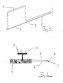
- FIG. 5 shows a functional part of a device according to the invention Calibration instrument, which is designated by the reference numeral 20.
- Another Part of the calibration instrument, which is also provided together with the part 20 is shown in Figure 7 and provided with the reference numeral 21.
- the instrument part 20 has a V-groove 14 bounded by the Nutebenen 15 and 16 becomes. Furthermore, a stop 17 is still provided on the right side of the instrument part 20.
- the front part in Figure 6 by the reference numeral 22 is designated.
- the bit has the cutting edge 2 on the edge vector 18 (peak vector) and a handle portion 23 with the axis vector 19th
- the instrument part 21 of the calibration instrument which is shown in FIG Functional elements have a recess defined by the planes A, B and C, wherein the Plane A is lowered parallel to the surface and planes B and C are perpendicular stand on top of each other and perpendicular to each other. Also, the chisel 22 is hinted.
- the cutting edge 2 of the bit becomes placed in a groove whose direction in space is known, for example, in the groove 14 of the instrument part 20 or in the section line of the planes A and B of the instrument part 21, the is also known (for example, not shown reflector arrangements).
- the cutting edge 2 of the bit is exactly in the groove 14 and at the edge between level A and level B, and geometry data of the calibration element are used for the calibration. Correct positioning of the bit relative to Calibration instrument 20, 21 is assumed.
- the rotation axis can be calculated and calculated with the position determined by the Grooving be adjusted. At about correct positioning (maintained threshold) become the geometry data of the calibration means used for calibration.
- cutting planes can be calibrated, when the bit, as that shown in Figure 2, has inclined surfaces, the Further also be referred to as cutting planes. It should be noted how the Cutting planes lie and at what angle they intersect.
- the chisel will be with his Cutting surfaces in two successive calibration steps to one of the planes, for Example level A, created.
- the cutting planes can be calibrated. When the cutting planes in a very acute angle to each other (infinitely thin chisel) is sufficient Circumstances the calibration of a cutting plane.
- the device according to the invention or the method according to the invention can be but also calibrate other properties of the chisel, for example, the width of his Cutting Edge 2.
- the width of the cutting surface 2 can be determined in their angle to each other, so here it is possible to also determine the width of the cutting surface 2 equal, namely, when - as shown in Figure 7 - the cutting edge 2 at the same time in the attack against the level C is created.
- a two-time application of the chisel of Each flat side then allows the calculation of the chisel width or the position of the axis vector 19 of the handle 23.
- a calibration of the chisel grip piece 23 is also using the V-groove 14th possible, which is shown on the instrument part 20 in Figure 5:
- the calibration of the axis vector 19 and the radius of the chisel grip section takes place by insertion into the V-groove 14 and performing a continuous rotational movement around the axis of rotation of the chisel.
- a fixed reference to the instrument (reflector arrangement) provides the tracking system with continuous data (samples). These will matched by computer aided graphics processing on a cylinder.
- the cylinder has initially any radius. Its axis, however, is parallel to the V-groove 14 and on the plane passing through the V-groove 14 and perpendicular to it, the V-groove opening angle halved vector is spanned.
- the initially variable radius of the Cylinder is after optimized match (for example, least square error, Standard deviation as plausibility check) the calibrated radius of the rotationally symmetric Part.
- optimized match for example, least square error, Standard deviation as plausibility check
- the calibrated radius of the rotationally symmetric Part can be done with the help of a manually entered Radius in case of another cylinder match the accuracy of the calibration of the vector.
- the chisel grip portion 23 is then calibrated, can by means of the already described above Technology, d. H. with the help of a lateral stop (level C in Figure 7), the bit width calibrated, with only one side of the edge of the blade must abut the plane C, since the axis vector 19 is known. With the above step, all necessary calibrations are now made on the instrument.
- a spanned by a reference (reflector adapter) Plane (for example, plane 6 in FIG. 2) parallel to the vector 8, 18 of the cutting edge 2, may be due to the individual calibration of the cutting edge orientation in space be waived.
- the axis vector 19 of the handle portion 23 be calibrated in conjunction with its length, for example, by the use of the stop 17 is possible, which is shown in Figure 5.
- the location and orientation of the edge vector 18 in space is then calculated by the predetermined parallelism to the reference plane (reference 5, Figure 2) plane spanned 6 and from the Axial vector 19 of the instrument, the edge vector 18 at a vertical angle cuts.
- the length of the cutting edge is then entered either manually or by Creation at the boundary plane C ( Figure 7) determined as described above.
Abstract
Description
Die vorliegende Erfindung betrifft die Navigations-Kalibrierung nicht rotationssymmetrischer, medizinischer Instrumente bzw. Implantate.The present invention relates to navigation calibration of non-rotationally symmetric, medical instruments or implants.
Die moderne, computergestützte Chirurgie ist in der Lage, während der Operation Instrumente oder Implantate des Chirurgen auf einem Monitor in Relation zu anatomischen Daten darzustellen, die vorher aus einem Patientenscan (CT, MR) erhalten wurden. Dazu müssen Informationen über das Instrument, beispielsweise über dessen räumliche Position und über die Lage des funktionellen Abschnittes, beispielsweise der Spitze des Instruments in dem verwendeten medizinischen Navigationssystem bekannt sein, d. h. die Instrumente bzw. die Implantate müssen kalibriert werden. Hierbei gibt es die Möglichkeit, eine Vorkalibrierung (prä-operative Kalibrierung) durchzuführen, d. h. dem Navigationssystem schon vorab die geometrischen Daten des Instruments bzw. des Implantats bekannt zu machen und softwareseitig fest zu speichern. Eine weitere Möglichkeit ist die sogenannte intra-operative Kalibrierung, bei der das Instrument bzw. das Implantat während der Operation vom behandelnden Personal kalibriert wird.Modern, computer-assisted surgery is capable of providing instruments during surgery or implants of the surgeon on a monitor in relation to anatomical data previously obtained from a patient scan (CT, MR). To do this Information about the instrument, for example about its spatial position and about the location of the functional portion, for example the tip of the instrument in the be known medical navigation system used, d. H. the instruments or the Implants must be calibrated. There is the possibility of a pre-calibration (pre-operative calibration), d. H. the navigation system in advance the geometric data of the instrument or the implant to make known and software side to save firmly. Another possibility is the so-called intra-operative calibration, at which the instrument or implant during the operation of the treating Personnel is calibrated.
Die Verwendung von prä-operativ kalibrierten Instrumenten bzw. Implantaten macht es in vielen Fällen trotzdem notwendig, intra-operativ die Genauigkeit der Instrumente zu überprüfen und eine Neukalibrierung durchzuführen. Ein weiterer Vorteil der intra-operativen Kalibrierung liegt darin, dass auf vorhandene Instrumente zurückgegriffen werden kann und man nicht auf die Instrumente angewiesen ist, deren Geometrie softwareseitig schon gespeichert ist. Mit anderen Worten kann jeder Chirurg beispielsweise seine eigenen Instrumente verwenden. Eine intra-operative Kalibrierung ist auch dann sehr wichtig, wenn sich Instrumente zwischen zwei Operationen verändert haben (zum Beispiel durch das Nachschleifen eines Instruments), jedoch während der Operation hochgenau kalibriert sein müssen. The use of pre-surgically calibrated instruments or implants makes it in Nevertheless, in many cases it is necessary to check the accuracy of the instruments intra-operatively and recalibrate. Another advantage of intra-operative calibration lies in the fact that existing instruments can be used and one does not depend on the instruments whose geometry has already been stored on the software side is. In other words, every surgeon can use his own instruments, for example. An intra-operative calibration is very important even when instruments are between have changed two operations (for example by regrinding an instrument), however, must be calibrated with high accuracy during the operation.
Eine intra-operative Kalibrierung kann auf verschiedene Arten erfolgen. Bei einer Kalibrierungsart nach dem Stand der Technik wird nur eine sogenannte Punktkalibrierung durchgeführt, d. h. es wird nur die Länge des Instruments bzw. Implantats bestimmt, aber nicht dessen Geometrie. Eine zweite und weiterführende Methode besteht darin, neben der Länge auch den exakten Vektor des Instruments, d. h. seine Geometrie zu bestimmen. Hierbei werden unterschiedliche Verfahren und Hilfsmittel eingesetzt, die sich jedoch derzeit sämtlich auf rotationssymmetrische Instrumente beschränken, welche sich sehr einfach kalibrieren lassen. Zu solchen Techniken wird auf die US 6,021,343, die WO 96/11624 und die US 5,921,922 hingewiesen. Aus letzterer Schrift ist eine intra-operative Kalibrierung von Instrumenten bekannt. Die Instrumente werden zur Kalibrierung während der Operation oder kurz vor der Verwendung in ein festes Kalibrierungstool eingespannt, also in eine Patienten- bzw. ortsfeste Einrichtung, in die das Instrument eingebracht wird, um es zu kalibrieren.Intra-operative calibration can be done in several ways. For a calibration type According to the prior art, only a so-called point calibration is performed, d. H. only the length of the instrument or implant is determined, but not its length Geometry. A second and advanced method is, in addition to the length of the exact vector of the instrument, d. H. to determine its geometry. Here are different Methods and tools used, but currently all on rotationally symmetric Limit instruments that are very easy to calibrate. To Such techniques are referred to US 6,021,343, WO 96/11624 and US 5,921,922. From the latter document, an intra-operative calibration of instruments is known. The instruments will be used for calibration during surgery or shortly before Use clamped in a fixed calibration tool, ie in a patient or stationary Device into which the instrument is inserted to calibrate it.
Der Nachteil des in der US 5,921,992 beschriebenen Systems liegt wiederum darin, dass eine Kalibrierung lediglich in Bezug auf die Ausrichtung des Instrumentes und dessen punktförmiger Spitze vorgenommen wird. Die im Rahmen dieser Offenbarung für die Kalibrierung geeigneten Instrumente sind lediglich solche, bei denen die Position der Instrumentenspitze sowie des anschließenden linear verlaufenden Abschnittes von Wichtigkeit bei der Behandlung sind.The disadvantage of the system described in US 5,921,992 is again that a Calibration only in relation to the orientation of the instrument and its punctiform Tip is made. The scope of this disclosure for calibration suitable instruments are only those in which the position of the instrument tip and the subsequent linear section of importance in the treatment are.
Es ist die Aufgabe der vorliegenden Erfindung, eine Kalibrierung auch für solche Instrumente bzw. Implantate zu ermöglichen, die nicht im Wesentlichen rotationssymmetrisch sind bzw. eine im Wesentlichen punktförmige Spitze haben. Insbesondere sollen komplex gestaltete Instrumente und Implantate für den optimalen Einsatz im Rahmen medizinischer Behandlungen kalibriert werden können.It is the object of the present invention to provide a calibration also for such instruments or implants that are not substantially rotationally symmetric have a substantially punctiform tip. In particular, should be designed complex Instruments and implants for optimal use in medical treatment can be calibrated.
Diese Aufgabe wird erfindungsgemäß durch ein Verfahren gemäß dem beiliegenden Anspruch
1, eine Vorrichtung gemäß dem beiliegenden Anspruch 10 sowie durch ein Programm
und ein Computerprogramm-Speichermedium gemäß den Ansprüchen 14 und 15 gelöst. Die
Unteransprüche definieren bevorzugte Ausführungsformen der Erfindung. This object is achieved by a method according to the accompanying
Das Verfahren gemäß der vorliegenden Erfindung zur Kalibrierung bzw. Registrierung medizinischer Instrumente bzw. Implantate ist seiner Gattung nach eines, bei dem eine räumliche Position des Instruments bzw. des Implantats mittels eines medizinischen Navigationssystems ermittelt wird, um die Relativposition des Instruments bzw. des Implantats gegenüber anatomischen Daten zu ermitteln. Da bei kompliziert ausgestalteten Instrumenten bzw. Implantaten eine Information über eine Spitzenposition bzw. eine einzige dargestellte Raumrichtung nicht ausreicht, um das Instrument bzw. das Implantat optimal in die Navigation einzubinden, wird gemäß der vorliegenden Erfindung die räumliche Ausrichtung eines mehrdimensional ausgestalteten, funktionellen Abschnitts des Instruments bzw. des Implantats ermittelt. Mit anderen Worten wird eine mehrdimensionale Kalibrierung des Instruments vorgenommen, es wird beispielsweise die Lage einer Ebene bzw. einer Kante des Instruments bestimmt, wenn diese von einer funktionellen Art ist, also falls es für die Funktion des Instrumentes bzw. des Implantats darauf ankommt, wie diese Ebene oder Kante im Raum angeordnet ist. Man könnte die erfindungsgemäße Kalibrierung auch als eine Kalibrierung von nicht rotationssymmetrischen Instrumenten bzw. Implantaten bezeichnen, und der besondere Vorteil der Erfindung beruht darin, dass eine optimierte Navigation solcher Instrumente und Implantate ermöglicht wird, was auch das Endresultat, beispielsweise die korrekte Schaffung eines Flächenschnittes mit einem Instrument oder das korrekte Einsetzen eines Implantats verbessert. Mit der vorliegenden Erfindung wird es somit möglich, auch komplizierter gestaltete Instrumente bzw. Implantate intra-operativ zu kalibrieren und damit die computergestützte Navigation auch hierfür nutzbar zu machen.The method according to the present invention for the calibration or registration of medical Instruments or implants is one of its kind according to a, in which a spatial Position of the instrument or the implant by means of a medical navigation system is determined to the relative position of the instrument or the implant against anatomical To determine data. As with complicated designed instruments or implants an information about a top position or a single displayed spatial direction not is sufficient to integrate the instrument or the implant optimally in the navigation is According to the present invention, the spatial orientation of a multi-dimensional designed, functional portion of the instrument or the implant determined. With others Words a multi-dimensional calibration of the instrument is made, it is For example, determines the location of a plane or an edge of the instrument, if this is of a functional nature, so if it is for the function of the instrument or the implant depends on how this plane or edge is arranged in space. You could do that Calibration according to the invention also as a calibration of non-rotationally symmetric Designate instruments or implants, and the particular advantage of the invention is based in that an optimized navigation of such instruments and implants is made possible, what also the final result, for example, the correct creation of a surface section with an instrument or the correct insertion of an implant. With the present Invention, it is thus possible even more complicated designed instruments or implants calibrate intra-operatively and thus the computer-assisted navigation for this purpose to make usable.
Gemäß einer bevorzugten Ausführungsform des erfindungsgemäßen Verfahrens wird die räumliche Ausrichtung eines linienförmigen, fünktionellen Abschnittes des Instrumentes bzw. des Implantats ermittelt. Wenn als Instrument beispielsweise ein chirurgischer Meißel zu verwenden ist, ist es vorteilhaft, die räumliche Ausrichtung der Schneidenfläche dieses Meißels zu ermitteln.According to a preferred embodiment of the method according to the invention is the spatial orientation of a linear, functional section of the instrument or of the implant. If as an instrument, for example, a surgical chisel too It is advantageous to use the spatial orientation of the cutting surface of this chisel to investigate.
Bei einer Ausführungsvariante des Verfahrens gemäß der vorliegenden Erfindung wird ein geeigneter Abschnitt des Instruments bzw. des Implantats an einem Kalibrierungsabschnitt eines Kalibrierungshilfsmittels ausgerichtet, dessen räumliche Ausrichtung im Navigationssystem bekannt ist und der getrackt wird. Es kann insbesondere der funktionelle Abschnitt selbst sein, der an dem Kalibrierungshilfsmittel bzw. an dessen Kalibrierungsabschnitt ausgerichtet wird, wobei dieser Kalibrierungsabschnitt bei einer Ausführungsform eine Linienform aufweisen kann, insbesondere eine Liniennut. Die Schneidenfläche eines chirurgischen Meißels kann beispielsweise in einer solchen Liniennut ausgerichtet werden.In one embodiment of the method according to the present invention is a appropriate portion of the instrument or implant at a calibration section aligned a calibration tool, its spatial orientation in the navigation system is known and is tracked. It may in particular be the functional section itself, which is aligned with the calibration aid or its calibration section in which, in one embodiment, this calibration section is a line shape may have, in particular a line groove. The cutting surface of a surgical chisel can be aligned for example in such a line groove.
Der oben angesprochene Kalibrierungsabschnitt kann im Rahmen der vorliegenden Erfindung aber auch eine Ebene am Kalibrierungshilfsmittel sein.The above-mentioned calibration section can be used in the context of the present invention but also be a level on the calibration tool.
In weiterer Ausgestaltung des erfindungsgemäßen Verfahrens wird die räumliche Ausrichtung des mehrdimensional ausgestalteten, funktionellen Abschnittes des Instruments bzw. des Implantats mit Hilfe schon vorhandener Informationen über die Ausrichtung einer bestimmten anderen, charakteristischen Linie oder Ebene für das Instrument bzw. das Implantat ermittelt.In a further embodiment of the method according to the invention, the spatial orientation the multi-dimensionally designed, functional section of the instrument or the Implant with the help of existing information on the orientation of a particular other, characteristic line or plane for the instrument or implant.
Im Rahmen der vorliegenden Erfindung besteht ferner die Möglichkeit, die räumliche Ausrichtung des mehrdimensional ausgestalteten, funktionellen Abschnitts des Instruments bzw. des Implantats mit Hilfe der Registrierung mehrerer Punkte auf dem Instrument bzw. Implantat durch ein schon kalibriertes Registrierungsinstrument zu ermitteln.In the context of the present invention, there is also the possibility of the spatial orientation of the multi-dimensional, functional section of the instrument or implant by registering multiple points on the instrument or implant determined by an already calibrated registration tool.
Die erfindungsgemäße Vorrichtung zur Kalibrierung bzw. Registrierung medizinischer Instrumente bzw. Implantate umfasst ein medizinisches Navigationssystem, und ein Kalibrierungshilfsmittel, wobei das Kalibrierungshilfsmittel einen Kalibrierungsabschnitt aufweist, dessen räumliche Ausrichtung im Navigationssystem bekannt ist und an dem ein mehrdimensional ausgestalteter, fünktioneller Abschnitt des Instruments bzw. des Implantats ausgerichtet werden kann.The inventive device for calibration or registration of medical instruments implants includes a medical navigation system, and a calibration tool, wherein the calibration aid has a calibration section, whose spatial orientation is known in the navigation system and in which a multidimensional aligned fünktioneller section of the instrument or the implant can be.
Bei einer Ausführungsform der erfindungsgemäßen Vorrichtung ist der Kalibrierungsabschnitt ein solcher, der eine Linienform, insbesondere die Form einer Liniennut aufweist, während gemäß einer anderen Ausführungsform ein Kalibrierungsabschnitt bereitgestellt wird, der eine Ebene ist.In one embodiment of the device according to the invention, the calibration section is one which has a line shape, in particular the shape of a line groove, while according to another embodiment, a calibration section is provided becomes, which is a plane.
Die Erfindung wird im Weiteren anhand bevorzugter Ausführungsbeispiele näher erläutert. Es zeigen:
Figur 1- die Kalibrierung eines chirurgischen Meißels mittels einer Kalibrierungsnut;
Figur 2- die Kalibrierung eines chirurgischen Meißels mit Hilfe einer bekannten Ebene;
Figur 3- die Kalibrierung eines chirurgischen Meißels mit Hilfe einer Kalibrierungsebene an einem Kalibrierungshilfsmittel;
Figur 4- die Kalibrierung eines chirurgischen Meißels mit Hilfe eines bereits registrierten Instruments; und
Figuren 5 bis 7- Darstellungen zur erfindungsgemäßen Kalibrierung, die eine konkrete Ausführungsform erläutern.
- FIG. 1
- the calibration of a surgical chisel by means of a calibration groove;
- FIG. 2
- the calibration of a surgical chisel using a known plane;
- FIG. 3
- the calibration of a surgical chisel by means of a calibration plane on a calibration aid;
- FIG. 4
- the calibration of a surgical chisel with the help of an already registered instrument; and
- FIGS. 5 to 7
- Representations for calibration according to the invention, which illustrate a concrete embodiment.
In Figur 1 wird dargestellt, wie die räumliche Ausrichtung der Schneidenfläche eines chirurgischen
Meißels erfindungsgemäß kalibriert werden kann. Der Meißel 1 weist eine Schneidenfläche
2 auf. Wenn nun mit diesem Meißel beispielsweise eine Knochenstruktur durchtrennt
werden soll, so ist es in manchen Fällen von großer Wichtigkeit, dass die Trennfläche
eine bestimmte Ausrichtung hat, insbesondere dann, wenn an dieser Trennfläche spezielle
Vorrichtungen angebracht werden sollen, deren Ausrichtung wiederum wichtig ist. Dazu ist
es im Rahmen der Navigation notwendig, die Ausrichtung der Schneidenfläche 2 zu kennen,
und im Rahmen der Kalibrierung kann eine solche Bestimmung beispielsweise dadurch erfolgen,
dass der Meißel 1 mit seiner Schneidenfläche 2 in die Nut 3' des nutförmigen Kalibrierungsinstrumentes
3 eingesetzt wird, wie es in Figur 1 prinzipiell dargestellt ist. Dabei wird
die Schneidenfläche 2 des Meißels mit Hilfe der bereits bekannten Geometrie der Nutlinie 3'
abgeglichen oder abgetastet. Diese Informationen werden gespeichert und ermöglichen die
Darstellung des Meißels während der Behandlung mit Hilfe des Navigationssystems. Die Lage
der Nut, die im Computer des Navigationssystems bekannt ist, kann als geometrischer
Datensatz auf das zu kalibrierende Instrument übertragen werden.In Figure 1 is shown how the spatial orientation of the cutting surface of a surgical
Chisels can be calibrated according to the invention. The
Eine andere, und die oben beschriebene Kalibrierung vorteilhaft ergänzende Möglichkeit für
die erfindungsgemäße, intra-operative Kalibrierung wird nunmehr anhand der PrinzipDarstellung
nach Figur 2 erläutert. Der dort dargestellte Meißel 4 hat eine Schneide 7 mit einer
Schneidenfläche 2. Die Ebene, in der die Schneidenfläche 2 liegt, ist mit dem Bezugszeichen
8 angedeutet. An dem Meißel ist eine Navigationsreferenz 5, im vorliegenden Fall ein
Referenzierungsadapter mit drei Reflektoren, angeordnet, dessen Lage im Navigationssystem
über Kameras bestimmbar ist. Damit ist auch die Ebene 6 bestimmbar, die parallel zur Ebene
8 ausgerichtet ist.Another, and the calibration described above advantageously complementary option for
the inventive, intra-operative calibration will now be based on the principle representation
explained according to FIG. The
Ist nun die von den Reflektoren aufgespannte Ebene parallel und mit bekanntem Abstand zur
Ebene 8 angebracht, so ist es möglich, beispielsweise durch das Anlegen der Schrägfläche 7
an eine bekannte Ebene, die Lage dieser Schrägfläche 7 sowie ihrer gespiegelten Fläche 7' zu
bestimmen bzw. zu kalibrieren. Dabei wird rechnerisch die Reflektorenebene 6 zur Ebene 8
hin verschoben und die Schnittgerade mit der Ebene, in der die vorher beispielsweise nach
Figur 1 bestimmte Schneidenfläche 2 liegt, berechnet. Durch das Spiegeln an der Ebene 8 ist
auch die gespiegelte Schrägfläche 7' kalibrierbar.Is now the plane spanned by the reflectors parallel and at a known distance to
Die Geometrie des Instruments kann nun in Relation zu anatomischen Daten vom Computer des Navigationssystems berechnet und auf einer Bildausgabe dargestellt werden.The geometry of the instrument can now be compared to anatomical data from the computer of the navigation system and displayed on an image output.
Gemäß der Ausführungsform nach Figur 3 wird ein Kalibrierungstool 12 verwendet, um die
Geometrie des Meißels 4 und insbesondere seiner Schneidenfläche 2 im Raum zu bestimmen.
Die Referenzierungseinrichtung 5 wird hierbei nicht primär benötigt, sie ist deshalb in schieier
Lage dargestellt. Das Kalibrierungshilfsmittel 12 weist eine Ebene 9 auf, deren Lage im
Raum bekannt ist. Mit anderen Worten erfolgt hierbei die Bestimmung der Geometrie des
Meißels im Raum mit Hilfe einer bekannten Ebene außerhalb des Meißels, wobei nach einer
Ausrichtung des Meißels, also beispielsweise einem Auflegen der Schneidenkante 2 auf die
bekannte Ebene 9, die Berechnung der Lage der Ebene 8 erfolgen kann, welche die Schneidenfläche
2 enthält, deren Raumrichtung beispielsweise durch ein Verfahren ermittelt wird,
wie es anhand der Figur 1 beschrieben wurde.According to the embodiment of FIG. 3, a
Gemäß der in Figur 4 dargestellten Ausführungsform wird die räumliche Ausrichtung des
Meißels 1 durch ein Abtastverfahren bestimmt. Dem Navigationssystem ist dabei schon die
Geometrie eines Instrumentes, beispielsweise eines hier schematisch dargestellten Pointers 11 .
bekannt und diese Information wird nunmehr zur Kalibrierung des Meißels 1 und dessen
Schneidenfläche 2 verwendet. Der Pointer 11 wird dazu mit seiner Spitze an unbestimmte
oder aber an vorher festgelegte Punkte des Meißels 1 herangebracht. Ein solcher Berührungspunkt
der Spitze des Pointers 11 mit dem Meißel ist in Figur 4 mit dem Bezugszeichen 10
angedeutet. Die gestrichelten Linien zeigen an, dass mit dem Pointer 11 auch weitere Punkte
angefahren werden.According to the embodiment shown in Figure 4, the spatial orientation of the
Da der Pointer 11 schon vorab kalibriert war und so die Position seiner Spitze im Navigationssystem
immer bekannt ist, werden die angefahrenen Punkte vom Navigationssystem erkannt
und dazu verwendet, die Ausrichtung des Meißels im Raum zu bestimmen und als Ausgangspunkt
für die Navigation abzuspeichern. Im Rahmen der Navigation kann dann diese
bekannte räumliche Ausrichtung des Meißels 1 in Bezug zu anderen Informationen (zum Beispiel
Anatomie des Patienten) dargestellt werden.Since the
Ein konkretes Ausführungsbeispiel für die erfindungsgemäße Kalibrierung wird nunmehr
anhand der Figuren 5 bis 7 erläutert. Die Figur 5 zeigt einen Funktionsteil eines erfindungsgemäßen
Kalibrierungsinstruments, der mit dem Bezugszeichen 20 bezeichnet wird. Ein anderer
Teil des Kalibrierungsinstruments, der ebenfalls zusammen mit dem Teil 20 bereitgestellt
werden kann, ist in Figur 7 gezeigt und mit dem Bezugszeichen 21 versehen.A concrete embodiment of the calibration according to the invention will now
explained with reference to Figures 5 to 7. FIG. 5 shows a functional part of a device according to the invention
Calibration instrument, which is designated by the
Der Instrumententeil 20 weist eine V-Nut 14 auf, die von den Nutebenen 15 und 16 begrenzt
wird. Ferner ist an der rechten Seite des Instrumententeils 20 noch ein Anschlag 17 vorgesehen.The
Mit diesem Kalibrierungsinstrument bzw. mit den Instrumententeilen 20 und 21 (Figuren 5
und 7) soll nunmehr ein Meißel kalibriert werden, dessen Vorderteil in Figur 6 mit dem Bezugszeichen
22 bezeichnet ist. Der Meißel weist die Schneidenkante 2 auf, die auf dem Kantenvektor
18 (Spitzenvektor) liegt sowie einen Griffabschnitt 23 mit dem Achsenvektor 19.With this calibration instrument or with the
Der Instrumententeil 21 des Kalibrierungsinstruments, der in Figur 7 dargestellt ist, weist als
Funktionselemente eine Aussparung auf, die von den Ebenen A, B und C definiert, wobei die
Ebene A gegenüber der Oberfläche parallel abgesenkt und die Ebenen B und C senkrecht
hierauf und aufeinander senkrecht stehen. Ebenfalls ist der Meißel 22 andeutungsweise dargestellt. The
Es soll nun im Weiteren anhand dieses konkreten Ausführungsbeispiels angedeutet werden, in welcher Weise erfindungsgemäß Kalibrierungen für einen solchen Meißel vorgenommen werden können.It will now be indicated below with reference to this specific embodiment, in which manner according to the invention made calibrations for such a chisel can be.
Was die Kalibrierung der räumlichen Ausrichtung der Schneidenfläche 2 des Meißels angeht,
so kann auch mit dem Kalibrierungsinstrument 20, 21 nach dem anhand von Figur 1 beschrieben
Prinzip vorgegangen werden. Dies bedeutet, die Schneidenkante 2 des Meißels wird
in ein Nut eingelegt, deren Raumrichtung bekannt ist, beispielsweise in die Nut 14 des Instrumententeils
20 oder in die Schnittlinie der Ebenen A und B des Instrumententeils 21, das
ebenfalls lagebekannt ist (beispielsweise über nicht dargestellte Reflektorenanordnungen).
Dabei wird die Schneidenkante 2 des Meißels genau in die Nut 14 bzw. an die Kante zwischen
der Ebene A und der Ebene B gelegt, und Geometriedaten des Kalibrierungselements
werden für die Kalibrierung verwendet. Eine korrekte Positionierung des Meißels relativ zum
Kalibrierungsinstrument 20, 21 wird dabei vorausgesetzt.As for the calibration of the spatial orientation of the cutting
Die Kalibrierung der Raumrichtung der Schneidenkante kann aber auch lediglich an einer
Ebene stattfinden, wenn die Ausrichtung dieser Ebene bekannt ist, wie beispielsweise diejenige
der Ebene B in Figur 7. Dabei wird der Meißel, der an seinem Griffabschnitt eine getrackte
Referenzierungseinrichtung (Reflektorenanordnung) aufweist, an irgendeiner Stelle an die
Ebene B mit der Schneidenkante 2 aufliegend angelegt und eine Rotationsbewegung wird um
die Schneidenkante 2 herum durchgeführt. Durch die Rotationsbewegung kann die Rotationsachse
(Schneidenkante) im Navigationssystem als Drehachse bestimmt und in ihrer Raumausrichtung
berechnet werden.The calibration of the spatial direction of the cutting edge but can also only at one
Level take place, if the orientation of this level is known, such as the one
the level B in Figure 7. This is the chisel, the one tracked at his grip section
Referencing device (reflector assembly) has, at any point to the
Plane B applied with the
Ebenfalls ist eine Kombination aus den beiden oben genannten Möglichkeiten zur Kalibrierung der Raumrichtung der Schneidenkante möglich. Durch die entstehende Redundanz ist ein Plausibilitätscheck möglich. So kann zum Beispiel die Rotationsachse berechnet und mit der durch die Nutanlage ermittelten Position abgeglichen werden. Bei in etwa richtiger Positionierung (eingehaltener Schwellwert) werden die Geometriedaten des Kalibrierungsmittels für die Kalibrierung verwendet. Also, a combination of the two above-mentioned options for calibration the spatial direction of the cutting edge possible. Due to the resulting redundancy is a plausibility check possible. For example, the rotation axis can be calculated and calculated with the position determined by the Grooving be adjusted. At about correct positioning (maintained threshold) become the geometry data of the calibration means used for calibration.
Als nächstes wird aufgezeigt, wie beispielsweise Schneidebenen kalibriert werden können, wenn der Meißel, wie derjenige, der in Figur 2 dargestellt ist, Schrägflächen aufweist, die im Weiteren auch als Schneidebenen bezeichnet werden. Hierbei ist festzustellen, wie die Schneidebenen liegen und unter welchem Winkel sie sich schneiden.Next, it will be shown how, for example, cutting planes can be calibrated, when the bit, as that shown in Figure 2, has inclined surfaces, the Further also be referred to as cutting planes. It should be noted how the Cutting planes lie and at what angle they intersect.
Einen ersten Lösungsansatz hierzu bietet die schon in Figur 4 aufgezeigte Kalibrierung, wobei - allgemein gesagt - mit einem spitzen Hilfsmittel dessen Geometriedaten bekannt sind, Punkte von beiden Ebenen aufgenommen und in diese Punktwolkeebenen eingepasst werden.A first approach to this end offers the already shown in Figure 4 calibration, wherein - generally speaking - with a pointed tool whose geometry data are known, Points from both planes can be picked up and fitted into these point cloud planes.
Eine weitere Möglichkeit besteht darin, die Schneidebenen an Ebenen des Kalibrierungsinstrumentes anzulegen, wie sie in Figur 7 bezeichnet sind. Der Meißel wird mit seinen Schneidflächen in zwei aufeinanderfolgenden Kalibrierungsschritten an eine der Ebenen, zum Beispiel Ebene A, angelegt. Durch die bekannten Geometriedaten des Kalibrierungsinstrumentes bzw. der Ebene A können die Schneidebenen kalibriert werden. Wenn die Schneidebenen in sehr spitzem Winkel zueinander stehen (unendlich dünner Meißel) genügt unter Umständen die Kalibrierung einer Schneidebene.Another possibility is to use the cutting planes at levels of the calibration instrument to apply, as they are designated in Figure 7. The chisel will be with his Cutting surfaces in two successive calibration steps to one of the planes, for Example level A, created. Through the known geometry data of the calibration instrument or level A, the cutting planes can be calibrated. When the cutting planes in a very acute angle to each other (infinitely thin chisel) is sufficient Circumstances the calibration of a cutting plane.
Es ist, wenn ein Meißel mit einer Referenzeinrichtung im Navigationssystem verwendet wird, auch möglich, beide Schneidebenen in einem einzigen Schritt zu kalibrieren. Dies gilt dann, wenn die von der Referenz aufgespannte Ebene parallel und mit bekanntem Abstand zum Meißel-Achsenvektor 19 (Figur 6) liegt. Es genügt dann, die Ebene der Referenzanordnung bis zur Mitte des Meißelgriffs hin zu verschieben und die Schnittgerade mit der Ebene des Kalibrierungsinstruments (zum Beispiel Ebene A) zu berechnen. Durch eine Spiegelung an der Mittelebene (verschobene Referenzebene) ist dann auch die andere Schneidebene kalibriert.It is when a chisel is used with a reference device in the navigation system, also possible to calibrate both cutting planes in a single step. This then applies if the plane spanned by the reference is parallel and with a known distance to the Chisel axis vector 19 (Figure 6) is located. It then suffices, the level of the reference arrangement to move to the middle of the chisel handle and the cutting line with the plane of the Calibration instrument (for example level A) to calculate. Through a reflection on the center plane (shifted reference plane) is calibrated then the other cutting plane.
Mit der erfindungsgemäßen Vorrichtung bzw. dem erfindungsgemäßen Verfahren lassen sich
aber auch noch weitere Eigenschaften des Meißels kalibrieren, beispielsweise die Breite seiner
Schneidenkante 2. Wenn wie oben beschrieben die Schneidebenen eines Meißels durch
zweimaliges Anlegen an die Ebene A in ihrem Winkel zueinander bestimmt werden können,
so besteht hierbei die Möglichkeit, auch die Breite der Schneidenfläche 2 gleich mitzubestimmen,
und zwar dann, wenn - wie in Figur 7 dargestellt ist - die Schneidenkante 2 gleichzeitig
im Anschlag an die Ebene C angelegt wird. Ein zweimaliges Anlegen des Meißels von
jeder Flachseite her gestattet dann die Berechnung der Meißelbreite bzw. der Lage des Achsenvektors
19 des Griffstücks 23.With the device according to the invention or the method according to the invention can be
but also calibrate other properties of the chisel, for example, the width of his
Eine Kalibrierung des Meißelgriffstücks 23 ist aber auch unter Verwendung der V-Nut 14
möglich, die am Instrumententeil 20 in Figur 5 gezeigt ist:A calibration of the
Die Kalibrierung des Achsenvektors 19 und des Radius des Meißelgriffabschnitts erfolgt
durch ein Einsetzen in die V-Nut 14 und ein Ausführen einer kontinuierlichen Drehbewegung
um die Rotationsachse des Meißels. Eine fest am Instrument angebrachte Referenz (Reflektorenanordnung)
liefert dabei dem Trackingsystem kontinuierlich Daten (Samples). Diese werden
durch computerunterstützte Graphikverarbeitung auf einen Zylinder gematcht. Der Zylinder
hat zunächst einen beliebigen Radius. Seine Achse liegt jedoch parallel zur V-Nut 14 und
auf der Ebene, die durch die V-Nut 14 und einen darauf senkrecht stehenden, den V-Nut-Öffnungswinkel
halbierenden Vektor aufgespannt wird. Der zunächst variable Radius des
Zylinders ist nach erfolgten optimiertem Match (zum Beispiel kleinster quadratischer Fehler,
Standardabweichung als Plausibilitätscheck) der kalibrierter Radius des rotationssymmetrischen
Teils. Für den Fall einer ungenauen Kalibrierung kann mit Hilfe eines manuell eingegebenen
Radius bei nochmals erfolgendem Zylindermatch die Genauigkeit der Kalibrierung
des Vektors erhöht werden.The calibration of the
Ist der Meißel-Griffabschnitt 23 dann kalibriert, kann mittels der oben schon beschriebenen
Technik, d. h. mit Hilfe eines seitlichen Anschlages (Ebene C in Figur 7) die Meißelbreite
kalibriert werden, wobei nur eine Seite der Schneidenkante an der Ebene C anliegen muss, da
der Achsenvektor 19 bekannt ist. Mit dem obigen Schritt sind nunmehr alle notwendigen Kalibrierungen
am Instrument vorgenommen.If the
Im Weiteren erfolgt die Beschreibung einer Kalibrierung eines Meißels (Schneidenkanten-Richtung im Raum und Griffabschnitt-Kalibrierung), die in lediglich einem einzigen Kalibrierungsschritt stattfinden kann. Below is the description of a calibration of a chisel (cutting edge direction in space and gripping section calibration), in just a single calibration step can take place.
Wenn nämlich sichergestellt ist, dass eine durch eine Referenz (Reflektorenadapter) aufgespannte
Ebene (zum Beispiel Ebene 6 in Figur 2) parallel zum Vektor 8, 18 der Schneidenkante
2 liegt, kann auf die Einzelkalibrierung der Schneidenkanten-Ausrichtung im Raum
verzichtet werden. Dann muss, wie oben zuletzt beschrieben, der Achsenvektor 19 des Griffabschnittes
23 in Verbindung mit seiner Länge kalibriert werden, was beispielsweise durch
die Verwendung des Anschlags 17 möglich wird, der in Figur 5 gezeigt ist. Die Lage und Orientierung
des Kantenvektors 18 im Raum errechnet sich dann durch die vorgegebene Parallelität
zu der von der Referenz (Bezugszeichen 5, Figur 2) aufgespannten Ebene 6 und aus dem
Achsenvektor 19 des Instruments, der dem Kantenvektor 18 unter senkrechtem Winkel
schneidet. Die Länge der Schneidenkante wird dann entweder manuell eingegeben oder durch
Anlegen an die Begrenzungsebene C (Figur 7) wie oben beschrieben ermittelt.Namely, if it is ensured that a spanned by a reference (reflector adapter)
Plane (for example,
Claims (15)
Priority Applications (4)
| Application Number | Priority Date | Filing Date | Title |
|---|---|---|---|
| EP02011600A EP1369090B1 (en) | 2002-05-28 | 2002-05-28 | Calibration of a navigation system for medical instruments and implants |
| DE50214813T DE50214813D1 (en) | 2002-05-28 | 2002-05-28 | Navigation calibration of medical instruments or implants |
| AT02011600T ATE491403T1 (en) | 2002-05-28 | 2002-05-28 | NAVIGATION CALIBRATION OF MEDICAL INSTRUMENTS OR IMPLANTS |
| US10/446,649 US7213598B2 (en) | 2002-05-28 | 2003-05-28 | Navigation-calibrating rotationally asymmetrical medical instruments or implants |
Applications Claiming Priority (1)
| Application Number | Priority Date | Filing Date | Title |
|---|---|---|---|
| EP02011600A EP1369090B1 (en) | 2002-05-28 | 2002-05-28 | Calibration of a navigation system for medical instruments and implants |
Publications (2)
| Publication Number | Publication Date |
|---|---|
| EP1369090A1 true EP1369090A1 (en) | 2003-12-10 |
| EP1369090B1 EP1369090B1 (en) | 2010-12-15 |
Family
ID=29433083
Family Applications (1)
| Application Number | Title | Priority Date | Filing Date |
|---|---|---|---|
| EP02011600A Expired - Lifetime EP1369090B1 (en) | 2002-05-28 | 2002-05-28 | Calibration of a navigation system for medical instruments and implants |
Country Status (3)
| Country | Link |
|---|---|
| EP (1) | EP1369090B1 (en) |
| AT (1) | ATE491403T1 (en) |
| DE (1) | DE50214813D1 (en) |
Cited By (4)
| Publication number | Priority date | Publication date | Assignee | Title |
|---|---|---|---|---|
| EP1570801A1 (en) * | 2004-03-03 | 2005-09-07 | Zimmer Technology, Inc. | Implant registration device for surgical navigation system |
| US9002432B2 (en) | 2004-11-15 | 2015-04-07 | Brainlab Ag | Method and device for calibrating a medical instrument |
| WO2015117644A1 (en) * | 2014-02-05 | 2015-08-13 | Brainlab Ag | Identification and calibration method |
| US10449005B2 (en) | 2013-03-20 | 2019-10-22 | Brainlab Ag | Adaptor for receiving a navigated structure which is at least a part of a medical object and method of registering a navigated structure using the adaptor |
Citations (3)
| Publication number | Priority date | Publication date | Assignee | Title |
|---|---|---|---|---|
| US6112113A (en) * | 1997-07-03 | 2000-08-29 | U.S. Philips Corporation | Image-guided surgery system |
| WO2001067979A1 (en) * | 2000-03-15 | 2001-09-20 | Orthosoft Inc. | Automatic calibration system for computer-aided surgical instruments |
| US20010034530A1 (en) * | 2000-01-27 | 2001-10-25 | Malackowski Donald W. | Surgery system |
Family Cites Families (1)
| Publication number | Priority date | Publication date | Assignee | Title |
|---|---|---|---|---|
| US5921992A (en) * | 1997-04-11 | 1999-07-13 | Radionics, Inc. | Method and system for frameless tool calibration |
-
2002
- 2002-05-28 AT AT02011600T patent/ATE491403T1/en active
- 2002-05-28 EP EP02011600A patent/EP1369090B1/en not_active Expired - Lifetime
- 2002-05-28 DE DE50214813T patent/DE50214813D1/en not_active Expired - Lifetime
Patent Citations (3)
| Publication number | Priority date | Publication date | Assignee | Title |
|---|---|---|---|---|
| US6112113A (en) * | 1997-07-03 | 2000-08-29 | U.S. Philips Corporation | Image-guided surgery system |
| US20010034530A1 (en) * | 2000-01-27 | 2001-10-25 | Malackowski Donald W. | Surgery system |
| WO2001067979A1 (en) * | 2000-03-15 | 2001-09-20 | Orthosoft Inc. | Automatic calibration system for computer-aided surgical instruments |
Cited By (5)
| Publication number | Priority date | Publication date | Assignee | Title |
|---|---|---|---|---|
| US6988009B2 (en) | 2003-02-04 | 2006-01-17 | Zimmer Technology, Inc. | Implant registration device for surgical navigation system |
| EP1570801A1 (en) * | 2004-03-03 | 2005-09-07 | Zimmer Technology, Inc. | Implant registration device for surgical navigation system |
| US9002432B2 (en) | 2004-11-15 | 2015-04-07 | Brainlab Ag | Method and device for calibrating a medical instrument |
| US10449005B2 (en) | 2013-03-20 | 2019-10-22 | Brainlab Ag | Adaptor for receiving a navigated structure which is at least a part of a medical object and method of registering a navigated structure using the adaptor |
| WO2015117644A1 (en) * | 2014-02-05 | 2015-08-13 | Brainlab Ag | Identification and calibration method |
Also Published As
| Publication number | Publication date |
|---|---|
| DE50214813D1 (en) | 2011-01-27 |
| EP1369090B1 (en) | 2010-12-15 |
| ATE491403T1 (en) | 2011-01-15 |
Similar Documents
| Publication | Publication Date | Title |
|---|---|---|
| EP1413258B1 (en) | Device and method for calibrating an element | |
| DE60119890T2 (en) | HAND FIXING DEVICE | |
| EP2599456B1 (en) | Surgical instrument | |
| EP2103270B1 (en) | System for navigation-supported shoulder operations for positioning navigated treatment devices relative to a bone | |
| DE19534136B4 (en) | External or internal fixator to restore the skeleton in case of fractures or arthroplasty | |
| DE10027988C2 (en) | Device for stereotaxically guided percutaneous implantation of the longitudinal connection of the pedicle screws | |
| DE102007053058B3 (en) | Surgical saw jig, has lower contact surface extending transverse to side surfaces for contacting bones, and wedge edge running at angle to longitudinal extension of contact surface, where angle deviates from specific degrees | |
| EP1348383A1 (en) | Retractor navigation device | |
| CH671873A5 (en) | ||
| DE102008023760A1 (en) | Position and condition determining arrangement for cross hole at intramedullary nail, has two cameras optically connected to markers by geometrical arrangement of markers to derive three 2-dimensional image coordinates | |
| EP2135575A1 (en) | Instrument alignment method with free reference | |
| DE102007011568A1 (en) | Medical clamp, in particular spinal clamp | |
| EP1354562B1 (en) | Improved bone fixation | |
| CH695846A5 (en) | Surgical instrument set for scarf osteotomy of metatarsal of bone, has osteotomy pad including two guiding channels, in which one channel forming acute angle is attached at one of two drilling wires, which are anchored at bones | |
| WO2007095917A2 (en) | Adjusting and guiding system for tools | |
| EP2422753A1 (en) | Set of instruments for twisting an implant into an intervertebral disc space | |
| EP3090687A1 (en) | Introduction and positioning device for puncture needles, associated kit and related methods | |
| DE102005047895B4 (en) | Method and device for determining the position of an object | |
| EP1369090B1 (en) | Calibration of a navigation system for medical instruments and implants | |
| EP2258290B1 (en) | Humeral nail for humerus fractures | |
| DE10343826B4 (en) | Bone-proof locator and navigation system | |
| EP1675520A1 (en) | Device for placing instruments or implants in body organs | |
| EP1648318B1 (en) | Device for fixing a longitudinal carrier to a bone fixing element | |
| EP3095398B1 (en) | Patient-specific instrument for the referencing of body parts | |
| EP3753501A1 (en) | Template and kits for domosteotomy |
Legal Events
| Date | Code | Title | Description |
|---|---|---|---|
| PUAI | Public reference made under article 153(3) epc to a published international application that has entered the european phase |
Free format text: ORIGINAL CODE: 0009012 |
|
| 17P | Request for examination filed |
Effective date: 20020528 |
|
| AK | Designated contracting states |
Kind code of ref document: A1 Designated state(s): AT BE CH CY DE DK ES FI FR GB GR IE IT LI LU MC NL PT SE TR |
|
| AX | Request for extension of the european patent |
Extension state: AL LT LV MK RO SI |
|
| 17Q | First examination report despatched |
Effective date: 20040202 |
|
| AKX | Designation fees paid |
Designated state(s): AT BE CH CY DE DK ES FI FR GB GR IE IT LI LU MC NL PT SE TR |
|
| APBN | Date of receipt of notice of appeal recorded |
Free format text: ORIGINAL CODE: EPIDOSNNOA2E |
|
| APBR | Date of receipt of statement of grounds of appeal recorded |
Free format text: ORIGINAL CODE: EPIDOSNNOA3E |
|
| APAF | Appeal reference modified |
Free format text: ORIGINAL CODE: EPIDOSCREFNE |
|
| APBT | Appeal procedure closed |
Free format text: ORIGINAL CODE: EPIDOSNNOA9E |
|
| RAP1 | Party data changed (applicant data changed or rights of an application transferred) |
Owner name: BRAINLAB AG |
|
| GRAP | Despatch of communication of intention to grant a patent |
Free format text: ORIGINAL CODE: EPIDOSNIGR1 |
|
| GRAS | Grant fee paid |
Free format text: ORIGINAL CODE: EPIDOSNIGR3 |
|
| GRAA | (expected) grant |
Free format text: ORIGINAL CODE: 0009210 |
|
| AK | Designated contracting states |
Kind code of ref document: B1 Designated state(s): AT BE CH CY DE DK ES FI FR GB GR IE IT LI LU MC NL PT SE TR |
|
| REG | Reference to a national code |
Ref country code: CH Ref legal event code: EP Ref country code: GB Ref legal event code: FG4D Free format text: NOT ENGLISH |
|
| REG | Reference to a national code |
Ref country code: IE Ref legal event code: FG4D |
|
| REF | Corresponds to: |
Ref document number: 50214813 Country of ref document: DE Date of ref document: 20110127 Kind code of ref document: P |
|
| REG | Reference to a national code |
Ref country code: NL Ref legal event code: VDEP Effective date: 20101215 |
|
| PG25 | Lapsed in a contracting state [announced via postgrant information from national office to epo] |
Ref country code: SE Free format text: LAPSE BECAUSE OF FAILURE TO SUBMIT A TRANSLATION OF THE DESCRIPTION OR TO PAY THE FEE WITHIN THE PRESCRIBED TIME-LIMIT Effective date: 20101215 Ref country code: CY Free format text: LAPSE BECAUSE OF FAILURE TO SUBMIT A TRANSLATION OF THE DESCRIPTION OR TO PAY THE FEE WITHIN THE PRESCRIBED TIME-LIMIT Effective date: 20101215 Ref country code: NL Free format text: LAPSE BECAUSE OF FAILURE TO SUBMIT A TRANSLATION OF THE DESCRIPTION OR TO PAY THE FEE WITHIN THE PRESCRIBED TIME-LIMIT Effective date: 20101215 Ref country code: FI Free format text: LAPSE BECAUSE OF FAILURE TO SUBMIT A TRANSLATION OF THE DESCRIPTION OR TO PAY THE FEE WITHIN THE PRESCRIBED TIME-LIMIT Effective date: 20101215 |
|
| REG | Reference to a national code |
Ref country code: IE Ref legal event code: FD4D |
|
| PG25 | Lapsed in a contracting state [announced via postgrant information from national office to epo] |
Ref country code: PT Free format text: LAPSE BECAUSE OF FAILURE TO SUBMIT A TRANSLATION OF THE DESCRIPTION OR TO PAY THE FEE WITHIN THE PRESCRIBED TIME-LIMIT Effective date: 20110415 Ref country code: IE Free format text: LAPSE BECAUSE OF FAILURE TO SUBMIT A TRANSLATION OF THE DESCRIPTION OR TO PAY THE FEE WITHIN THE PRESCRIBED TIME-LIMIT Effective date: 20101215 Ref country code: ES Free format text: LAPSE BECAUSE OF FAILURE TO SUBMIT A TRANSLATION OF THE DESCRIPTION OR TO PAY THE FEE WITHIN THE PRESCRIBED TIME-LIMIT Effective date: 20110326 Ref country code: GR Free format text: LAPSE BECAUSE OF FAILURE TO SUBMIT A TRANSLATION OF THE DESCRIPTION OR TO PAY THE FEE WITHIN THE PRESCRIBED TIME-LIMIT Effective date: 20110316 |
|
| PLBE | No opposition filed within time limit |
Free format text: ORIGINAL CODE: 0009261 |
|
| STAA | Information on the status of an ep patent application or granted ep patent |
Free format text: STATUS: NO OPPOSITION FILED WITHIN TIME LIMIT |
|
| PG25 | Lapsed in a contracting state [announced via postgrant information from national office to epo] |
Ref country code: DK Free format text: LAPSE BECAUSE OF FAILURE TO SUBMIT A TRANSLATION OF THE DESCRIPTION OR TO PAY THE FEE WITHIN THE PRESCRIBED TIME-LIMIT Effective date: 20101215 |
|
| 26N | No opposition filed |
Effective date: 20110916 |
|
| BERE | Be: lapsed |
Owner name: BRAINLAB A.G. Effective date: 20110531 |
|
| PG25 | Lapsed in a contracting state [announced via postgrant information from national office to epo] |
Ref country code: MC Free format text: LAPSE BECAUSE OF NON-PAYMENT OF DUE FEES Effective date: 20110531 Ref country code: IT Free format text: LAPSE BECAUSE OF FAILURE TO SUBMIT A TRANSLATION OF THE DESCRIPTION OR TO PAY THE FEE WITHIN THE PRESCRIBED TIME-LIMIT Effective date: 20101215 |
|
| REG | Reference to a national code |
Ref country code: CH Ref legal event code: PL |
|
| REG | Reference to a national code |
Ref country code: DE Ref legal event code: R097 Ref document number: 50214813 Country of ref document: DE Effective date: 20110916 |
|
| PG25 | Lapsed in a contracting state [announced via postgrant information from national office to epo] |
Ref country code: CH Free format text: LAPSE BECAUSE OF NON-PAYMENT OF DUE FEES Effective date: 20110531 Ref country code: LI Free format text: LAPSE BECAUSE OF NON-PAYMENT OF DUE FEES Effective date: 20110531 |
|
| PG25 | Lapsed in a contracting state [announced via postgrant information from national office to epo] |
Ref country code: BE Free format text: LAPSE BECAUSE OF NON-PAYMENT OF DUE FEES Effective date: 20110531 |
|
| REG | Reference to a national code |
Ref country code: AT Ref legal event code: MM01 Ref document number: 491403 Country of ref document: AT Kind code of ref document: T Effective date: 20110528 |
|
| PG25 | Lapsed in a contracting state [announced via postgrant information from national office to epo] |
Ref country code: AT Free format text: LAPSE BECAUSE OF NON-PAYMENT OF DUE FEES Effective date: 20110528 |
|
| PG25 | Lapsed in a contracting state [announced via postgrant information from national office to epo] |
Ref country code: LU Free format text: LAPSE BECAUSE OF NON-PAYMENT OF DUE FEES Effective date: 20110528 |
|
| PG25 | Lapsed in a contracting state [announced via postgrant information from national office to epo] |
Ref country code: TR Free format text: LAPSE BECAUSE OF FAILURE TO SUBMIT A TRANSLATION OF THE DESCRIPTION OR TO PAY THE FEE WITHIN THE PRESCRIBED TIME-LIMIT Effective date: 20101215 |
|
| REG | Reference to a national code |
Ref country code: DE Ref legal event code: R082 Ref document number: 50214813 Country of ref document: DE Representative=s name: SCHWABE SANDMAIR MARX, DE |
|
| REG | Reference to a national code |
Ref country code: DE Ref legal event code: R081 Ref document number: 50214813 Country of ref document: DE Owner name: BRAINLAB AG, DE Free format text: FORMER OWNER: BRAINLAB AG, 85622 FELDKIRCHEN, DE Effective date: 20131104 Ref country code: DE Ref legal event code: R082 Ref document number: 50214813 Country of ref document: DE Representative=s name: SCHWABE SANDMAIR MARX, DE Effective date: 20131104 Ref country code: DE Ref legal event code: R082 Ref document number: 50214813 Country of ref document: DE Representative=s name: SCHWABE SANDMAIR MARX PATENTANWAELTE RECHTSANW, DE Effective date: 20131104 |
|
| REG | Reference to a national code |
Ref country code: FR Ref legal event code: PLFP Year of fee payment: 15 |
|
| REG | Reference to a national code |
Ref country code: DE Ref legal event code: R082 Ref document number: 50214813 Country of ref document: DE Representative=s name: SCHWABE SANDMAIR MARX PATENTANWAELTE RECHTSANW, DE Ref country code: DE Ref legal event code: R081 Ref document number: 50214813 Country of ref document: DE Owner name: BRAINLAB AG, DE Free format text: FORMER OWNER: BRAINLAB AG, 85622 FELDKIRCHEN, DE Ref country code: DE Ref legal event code: R082 Ref document number: 50214813 Country of ref document: DE Representative=s name: SSM SANDMAIR PATENTANWAELTE RECHTSANWALT PARTN, DE |
|
| REG | Reference to a national code |
Ref country code: FR Ref legal event code: PLFP Year of fee payment: 16 |
|
| REG | Reference to a national code |
Ref country code: FR Ref legal event code: CA Effective date: 20170706 |
|
| REG | Reference to a national code |
Ref country code: FR Ref legal event code: PLFP Year of fee payment: 17 |
|
| PGFP | Annual fee paid to national office [announced via postgrant information from national office to epo] |
Ref country code: DE Payment date: 20210520 Year of fee payment: 20 Ref country code: FR Payment date: 20210520 Year of fee payment: 20 |
|
| PGFP | Annual fee paid to national office [announced via postgrant information from national office to epo] |
Ref country code: GB Payment date: 20210520 Year of fee payment: 20 |
|
| REG | Reference to a national code |
Ref country code: DE Ref legal event code: R071 Ref document number: 50214813 Country of ref document: DE |
|
| REG | Reference to a national code |
Ref country code: GB Ref legal event code: PE20 Expiry date: 20220527 |
|
| PG25 | Lapsed in a contracting state [announced via postgrant information from national office to epo] |
Ref country code: GB Free format text: LAPSE BECAUSE OF EXPIRATION OF PROTECTION Effective date: 20220527 |