EP1365833B1 - Implantable heart stimulator - Google Patents
Implantable heart stimulator Download PDFInfo
- Publication number
- EP1365833B1 EP1365833B1 EP02701839A EP02701839A EP1365833B1 EP 1365833 B1 EP1365833 B1 EP 1365833B1 EP 02701839 A EP02701839 A EP 02701839A EP 02701839 A EP02701839 A EP 02701839A EP 1365833 B1 EP1365833 B1 EP 1365833B1
- Authority
- EP
- European Patent Office
- Prior art keywords
- heart stimulator
- implantable heart
- electrode
- lead
- implantable
- Prior art date
- Legal status (The legal status is an assumption and is not a legal conclusion. Google has not performed a legal analysis and makes no representation as to the accuracy of the status listed.)
- Expired - Lifetime
Links
Images

Classifications
-
- A—HUMAN NECESSITIES
- A61—MEDICAL OR VETERINARY SCIENCE; HYGIENE
- A61N—ELECTROTHERAPY; MAGNETOTHERAPY; RADIATION THERAPY; ULTRASOUND THERAPY
- A61N1/00—Electrotherapy; Circuits therefor
- A61N1/02—Details
- A61N1/04—Electrodes
- A61N1/05—Electrodes for implantation or insertion into the body, e.g. heart electrode
- A61N1/056—Transvascular endocardial electrode systems
-
- A—HUMAN NECESSITIES
- A61—MEDICAL OR VETERINARY SCIENCE; HYGIENE
- A61N—ELECTROTHERAPY; MAGNETOTHERAPY; RADIATION THERAPY; ULTRASOUND THERAPY
- A61N1/00—Electrotherapy; Circuits therefor
- A61N1/18—Applying electric currents by contact electrodes
- A61N1/32—Applying electric currents by contact electrodes alternating or intermittent currents
- A61N1/36—Applying electric currents by contact electrodes alternating or intermittent currents for stimulation
- A61N1/372—Arrangements in connection with the implantation of stimulators
- A61N1/375—Constructional arrangements, e.g. casings
- A61N1/37512—Pacemakers
Definitions
- the present invention relates to an infection control apparatus for an implantable heart stimulator comprising a pulse generator for delivering electric stimulation pulses to a patient's heart through a lead connectable to said pulse generator, possibly through a connector top on a pulse generator housing, said pulse generator housing being electrically conductive.
- Implantable heart stimulator pocket infection is a severe complication which often ends up in explantation of the stimulator.
- the reason therefor is that conventional treatment with antibiotics cannot eradicate the infection. This seems to depend on the circumstance that the bacteria live in a biofilm formed around the exterior surfaces of the implanted stimulator, which film blocks antibiotics. The bacteria may also live passively on a very low metabolism and can therefore not be treated successfully by antibiotics.
- the polymer surface of the lead may be a substrate for the bacteria and makes it easy for the bacteria to attach. At the time when a pocket infection is clinically manifested, in many cases the infection has already spread some distance from the stimulator pocket along the lead.
- the bioelectric effect is limited to conducting surfaces of the implanted device or to the immediate proximity thereof.
- a design is obtained which makes it possible to extend the bioelectric effect to traditionally non conducting surfaces of an implanted heart stimulator, like a pacemaker or a cardioverter - defibrillator (ICD).
- ICD cardioverter - defibrillator
- an electrically conducting polymer is applied on said exterior surfaces of the proximal part of said lead and said possible connector top.
- non-conducting surfaces of a heart stimulator are made electrically conductive.
- An example of a polymer suitable for this purpose is an electrically conducting polymer marketed under the trademark ELASTOSIL.
- an electrically conducting coil is applied around said proximal part of the lead.
- the proximal part of the lead is made not only electrically conductive but the wear resistance of the lead is improved.
- the exterior surfaces of the proximal part of the lead and of said possible connector top are treated by ion implantation technology or so-called Ion-Beam-Assisted-Deposition.
- This technique is especially well suited for making stimulator connector tops or headers of epoxy electrically conductive.
- Other possible coating technologies are Physical Vapour Deposition, PVD, or Chemical Vapour Deposition, CVD, or any sputtering process.
- oxide layers especially titanium oxide layers but also other metal oxide layers, may be found when such metals are used in the DC current environment dealt with in conjunction with the present invention. These oxide layers may cause an uneven current distribution which is detrimental to the infection control effect. The current may also be lowered due to increased impedance because of the oxide layer to a point at which the effect on bacteria in the biofilm is no longer effective.
- the formation of such oxide layers is avoided, according to an advantageous embodiment of the apparatus according to the invention, by coating the generator housing, and other metallic surfaces that may become oxidised due to the DC current, with one of the metals platinum, palladium or iridium or any other metal with similar electro-chemical characteristics or an alloy of these metals
- said counter electrode is an implantable electrode, suitably designed to be positioned on said lead for implantation into the patient's heart, preferably a heart stimulation electrode is forming said counter electrode.
- a heart stimulation electrode is forming said counter electrode.
- the electrical infection treatment has to be performed such that it does not interfere with stimulation pulses of the heart stimulator.
- the treatment has to be restricted to the heart's refractory periods, or, alternatively, an infection treatment current of such a high frequency is used that the heart is not affected.
- said counter electrode is formed of a large surface defibrillation electrode
- said counter electrode can be designed for external application to the patient's skin, preferably formed of a patch electrode for external application to the patient's skin.
- a galvanic connecting means is provided to galvanically connect to said current source to implanted electrodes through the patient's skin according to an advantageous embodiment of the apparatus according to the invention.
- means are provided to inductively couple said externally located current source to said electrodes.
- the inductive coupling means comprise a thin inductive coil attached to the outer surface of the pulse generator housing and electrically connected to the electrodes or an inductive coil positioned inside the pulse generator housing and electrically connected to the electrodes.
- Such thin coils which are manufactured preferably by screen printing, will not require much space and will consequently contribute to a compact stimulator construction.
- Such a coil might also be used as a telemetry coil.
- a rectifying means is connected between said coil and one of the electrodes to supply a DC current to the electrodes.
- an electrolytic connecting means for electrolytically connecting said current source to said first electrode.
- Said electrolytic connecting means preferably comprises an additional electrode for external application to the patient's skin, separated from said counter electrode and in electrolytic contact with said first electrode, said current source being connected to said counter electrode and to said additional electrode.
- the biofluid of the patient's body can then serve as electrolytic medium. In this way the great advantage of a non-invasive connection without transcutaneous wires is obtained.
- the current distribution on the housing and implanted electrode respectively might be non-uniform. This can be, at least partly, remedied by repositioning the external electrodes during the treatment, such that all implanted surfaces are coated by an adequate quantity of current.
- the present invention also relates to a heart stimulator comprising a pulse generator for delivering electric stimulation pulses to a patient's heart through a lead, connectable to said pulse generator, possibly through a connector top on a pulse generator housing, said pulse generator housing be electrically conductive, which stimulator is characterised by an apparatus as disclosed above.
- the proximal part of the lead extending to a position which after implantation of the lead is situated between a location beyond the entry into the venous system and the entry into vena cava superior, is made electrically conductive.
- the proximal part can be made electrically conductive by e.g. applying an electrically conducting polymer on its surface or by ion implantation technology or Ion-Beam-Assisted-Deposition (IBAD).
- IBAD Ion-Beam-Assisted-Deposition
- figure 1 shows schematically an implantable heart stimulator 2 having a connector top 4 to which a lead 6 is connected.
- the proximal part of the lead 6 is made electrically conductive by wrapping a metallic coil 8 around this part of the lead.
- the metallic coil 8 will also improve the wear resistance of the lead 6.
- the connector top or header 4 is often made of epoxy and IBAD is a suitable technique for making such a connector top conductive
- Figure 2 shows an embodiment with electrically conductive exterior surfaces of the generator housing 10, the connector top 12 and the proximal part 16 of the lead 14.
- the generator housing 10, the connector top 12 and the proximal part 16 of the lead 14 are forming one electrode, whereas a large surface right ventricular defibrillating electrode 19 on the lead 14 is used as counter electrode.
- the pulse generator battery can be operable to deliver an infection control electric current i between this defibrillation electrode 19 and the electrode formed by the conductive housing 10, the connector top 12 and the proximal lead part 16 to destroy bacteria residing in a biofilm on the implanted stimulator.
- This electrical treatment current i must not interfere with the stimulating function of the heart stimulator and is therefore delivered during the heart's 21 refractory period.
- implantable indifferent electrodes are disclosed in e.g. US 5,510,766 and US 5,814,076, these electrodes, however, being used for other purposes.
- the electric infection control requires a comparatively high amount of energy and therefore an external power source is normally needed.
- Transcutaneous electric connections to implanted electrodes increase the risk of recontamination of the wound and discomfort for the patient. It would therefore be a great advantage to use a non-invasive method for the energy supply.
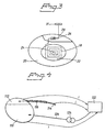
- FIG. 3 shows an example of supplying electric current for infection control from an external source by electromagnetic induction.
- a super thin surface mounted coil 18 is attached to the exterior surface of the stimulator housing 20.
- This coil 18 can be manufactured by e.g. screen printing.
- a polymeric isolation film 22 is provided to electrically isolate the coil 18 from the stimulator housing 20.
- One end 24 of the coil 18 is electrically connected to the housing 20, while the other end is connected to a diode 26 integrated in the epoxy connector head 28.
- the diode 26, in its turn, is connected to a counter electrode 31.
- the coil can be implemented inside the stimulator housing. One end of the coil is then connected to the stimulator housing, whereas the other end of the coil is connected via a diode to an external counter electrode.
- Figure 4 shows an embodiment with the pulse generator housing 10, the connector top 112 and the proximal part 116 of the lead 114 forming one electrode, whereas an external patch electrode 122, intended for application on the patient's skin, is used as counter electrode.
- an external current source 124 is used for delivering treatment current i.
- an electrically conductive needle 126 connected to the current source 124, is inserted through the patient's skin to make contact with a pulse generator housing 10.
- a connecting means can be used for electrolytically connecting an external current source to an implanted electrode.
- the electrolytic connecting means can comprise an additional electrode for external application to the patient's skin, separated from the counter electrode and in electrolytic contact with said first electrode via the body biofluid.
- these electrodes should preferably be positioned such that those parts of the infection control current, which pass through the heart, are minimised.
Description
- The present invention relates to an infection control apparatus for an implantable heart stimulator comprising a pulse generator for delivering electric stimulation pulses to a patient's heart through a lead connectable to said pulse generator, possibly through a connector top on a pulse generator housing, said pulse generator housing being electrically conductive.
- Implantable heart stimulator pocket infection is a severe complication which often ends up in explantation of the stimulator. The reason therefor is that conventional treatment with antibiotics cannot eradicate the infection. This seems to depend on the circumstance that the bacteria live in a biofilm formed around the exterior surfaces of the implanted stimulator, which film blocks antibiotics. The bacteria may also live passively on a very low metabolism and can therefore not be treated successfully by antibiotics.
- A method of enhancing the effect of antibiotics by applying an electrical field across the biofilm is described in US 5,312,813. This method is based on findings by J.W. Costerton et.al. Their studies have shown that the infection can be completely cured and no explantation has to take place by applying an electric field or a small current across the biofilm during antibiotic treatment, cf. also ASAIO Journal 1992, p.M174 - M178, Khoury et.al, "Prevention and Control of Bacterial Infections Associated with Medical Devices", and Antimicrobial Agents and Chemotherapy, Vol.38, No. 12, Dec.1994, p.2803-2809, Costerton et.al., "Mechanism of Electrical Enhancement of Efficacy of Antibiotics in Killing Biofilm Bacteria" In these studies, generally, a low electric current of the order of 15-400 µA/cm2 is applied onto the infected surface while they were immersed in a buffer with antibiotics. In the most successful studies a total killing of microorganisms was reported after only 8 hours of current and antibiotic treatment - tobramycin 2.5 mg/l, 15-400 µA/cm2, during 8h. This effect has been termed "the bioelectric effect".
- These studies suggest that the electric field need to be applied in close proximity to the infected implant. A passive electric field will not due, but a current should be conducted between electrodes in the biofluid surrounding the implanted device. A possible explanation to the observed effect is that electrochemically generated products are needed for the bioelectric effect to occur. At the titanium surface, titanium being normally used in heart stimulator housings, the following electrochemical processes take place.
- At the anode:
- 1)
- 2)
- 3)
-
- At the cathode:
- 1)
- 2)
-
- It is supposed that primarily the produced oxygen and chloride gases have an influence on the biofilm attached to the surface. It is also supposed that the fact that the pH-value is lowered at the anode and increased at the cathode is significant for the influence and viability of the biofilm.
- An infection that is initiated in the stimulator pocket will also often start to spread along the lead. The polymer surface of the lead may be a substrate for the bacteria and makes it easy for the bacteria to attach. At the time when a pocket infection is clinically manifested, in many cases the infection has already spread some distance from the stimulator pocket along the lead.
- As the bioelectric effect is concentrated to parts in conjunction with or in close proximity to conducting surfaces of the implant, it is the purpose of the present invention to extend these conducting active surfaces to practically the whole exterior surface of the implant, such that it can be current covered.
- This purpose is obtained by an apparatus of the type defined in the introductory portion of the description and having the characterising features of claim 1.
- As discussed above the bioelectric effect is limited to conducting surfaces of the implanted device or to the immediate proximity thereof. With the present invention a design is obtained which makes it possible to extend the bioelectric effect to traditionally non conducting surfaces of an implanted heart stimulator, like a pacemaker or a cardioverter - defibrillator (ICD). By making also exterior surfaces of the proximal part of the lead and a possible connector top electrically conductive all exterior stimulator surfaces located within the subcutaneous implant pocket and a part of the lead extending from the pocket are electrically conductive, and by adapting these electrically conductive surfaces to form at least two separate electrodes and providing a current source to supply an electric infection control current between these electrodes all exterior surfaces will be current coated, and the bioelectric effect will be extended to all surfaces within the pocket and also to the exterior surface of the proximal part of the lead. By making the normally non-conducting surfaces of the connector top and the lead electrically conducting not only effective treatment of infections within the pocket is possible, but spreading of the infection from the pocket along the lead is prevented. The lead will in this way benefit from the bioelectric effect and thus it is prevented that bacteria reach the endocardium giving rise to endocarditis.
- According to an advantageous embodiment of the apparatus according to the invention an electrically conducting polymer is applied on said exterior surfaces of the proximal part of said lead and said possible connector top. In this way traditionally non-conducting surfaces of a heart stimulator are made electrically conductive. An example of a polymer suitable for this purpose is an electrically conducting polymer marketed under the trademark ELASTOSIL.
- According to another advantageous embodiment of the apparatus according to the invention an electrically conducting coil is applied around said proximal part of the lead. In this way the proximal part of the lead is made not only electrically conductive but the wear resistance of the lead is improved.
- According to still another advantageous embodiment of the apparatus according to the invention the exterior surfaces of the proximal part of the lead and of said possible connector top are treated by ion implantation technology or so-called Ion-Beam-Assisted-Deposition. This technique is especially well suited for making stimulator connector tops or headers of epoxy electrically conductive. Other possible coating technologies are Physical Vapour Deposition, PVD, or Chemical Vapour Deposition, CVD, or any sputtering process.
- It has been found that oxide layers, especially titanium oxide layers but also other metal oxide layers, may be found when such metals are used in the DC current environment dealt with in conjunction with the present invention. These oxide layers may cause an uneven current distribution which is detrimental to the infection control effect. The current may also be lowered due to increased impedance because of the oxide layer to a point at which the effect on bacteria in the biofilm is no longer effective. The formation of such oxide layers is avoided, according to an advantageous embodiment of the apparatus according to the invention, by coating the generator housing, and other metallic surfaces that may become oxidised due to the DC current, with one of the metals platinum, palladium or iridium or any other metal with similar electro-chemical characteristics or an alloy of these metals
- According to still other advantageous embodiments of the apparatus according to the invention said counter electrode is an implantable electrode, suitably designed to be positioned on said lead for implantation into the patient's heart, preferably a heart stimulation electrode is forming said counter electrode. The need of a separate implanted counter electrode is then eliminated. In this case the electrical infection treatment has to be performed such that it does not interfere with stimulation pulses of the heart stimulator. Thus the treatment has to be restricted to the heart's refractory periods, or, alternatively, an infection treatment current of such a high frequency is used that the heart is not affected.
- According to yet other advantageous embodiments of the apparatus according to the invention said counter electrode is formed of a large surface defibrillation electrode, said counter electrode can be designed for external application to the patient's skin, preferably formed of a patch electrode for external application to the patient's skin. By using large surface electrodes the current density will be lower and a uniform current distribution is more easily obtained.
- When using an external current source, which is natural particularly in case of a counter electrode for external application, a galvanic connecting means is provided to galvanically connect to said current source to implanted electrodes through the patient's skin according to an advantageous embodiment of the apparatus according to the invention.
- According to other advantageous embodiments of the apparatus according to the invention means are provided to inductively couple said externally located current source to said electrodes.
- According to other advantageous embodiments of the apparatus according to the invention the inductive coupling means comprise a thin inductive coil attached to the outer surface of the pulse generator housing and electrically connected to the electrodes or an inductive coil positioned inside the pulse generator housing and electrically connected to the electrodes. Such thin coils, which are manufactured preferably by screen printing, will not require much space and will consequently contribute to a compact stimulator construction. Such a coil might also be used as a telemetry coil.
- According to still another advantageous embodiment of the apparatus according to the invention a rectifying means is connected between said coil and one of the electrodes to supply a DC current to the electrodes.
- According to other advantageous embodiments of the apparatus according to the invention with said current source located externally an electrolytic connecting means is provided for electrolytically connecting said current source to said first electrode. Said electrolytic connecting means preferably comprises an additional electrode for external application to the patient's skin, separated from said counter electrode and in electrolytic contact with said first electrode, said current source being connected to said counter electrode and to said additional electrode. The biofluid of the patient's body can then serve as electrolytic medium. In this way the great advantage of a non-invasive connection without transcutaneous wires is obtained. When using two external (patch) electrodes the current distribution on the housing and implanted electrode respectively might be non-uniform. This can be, at least partly, remedied by repositioning the external electrodes during the treatment, such that all implanted surfaces are coated by an adequate quantity of current.
- The present invention also relates to a heart stimulator comprising a pulse generator for delivering electric stimulation pulses to a patient's heart through a lead, connectable to said pulse generator, possibly through a connector top on a pulse generator housing, said pulse generator housing be electrically conductive, which stimulator is characterised by an apparatus as disclosed above.
- To explain the invention in greater detail embodiments of the apparatus according to the invention will now be described with reference to the drawings, on which
- Figure 1
- shows schematically a heart stimulator with a lead provided with a coil on its proximal part,
- Figure 2
- shows an embodiment with a large surface ventricular defibrillating electrode as counter electrode,
- Figure 3
- shows schematically a heart stimulator with a surface mounted coil on the exterior of the stimulator housing for inductively connecting an external current source to the electrode forming parts of the implant, and
- Figure 4
- shows an embodiment of the invention with an external patch electrode as counter electrode.
- In the apparatus according to the invention a. o. the proximal part of the lead extending to a position which after implantation of the lead is situated between a location beyond the entry into the venous system and the entry into vena cava superior, is made electrically conductive. This can be realised in several different ways. Thus the proximal part can be made electrically conductive by e.g. applying an electrically conducting polymer on its surface or by ion implantation technology or Ion-Beam-Assisted-Deposition (IBAD). In figure 1 another example of making a proximal lead part electrically conductive is shown.
- Thus figure 1 shows schematically an
implantable heart stimulator 2 having aconnector top 4 to which a lead 6 is connected. The proximal part of the lead 6 is made electrically conductive by wrapping ametallic coil 8 around this part of the lead. Themetallic coil 8 will also improve the wear resistance of the lead 6. - The connector top or
header 4 is often made of epoxy and IBAD is a suitable technique for making such a connector top conductive - Figure 2 shows an embodiment with electrically conductive exterior surfaces of the
generator housing 10, theconnector top 12 and theproximal part 16 of thelead 14. Thegenerator housing 10, theconnector top 12 and theproximal part 16 of thelead 14 are forming one electrode, whereas a large surface right ventricular defibrillatingelectrode 19 on thelead 14 is used as counter electrode. The pulse generator battery can be operable to deliver an infection control electric current i between thisdefibrillation electrode 19 and the electrode formed by theconductive housing 10, theconnector top 12 and the proximallead part 16 to destroy bacteria residing in a biofilm on the implanted stimulator. This electrical treatment current i must not interfere with the stimulating function of the heart stimulator and is therefore delivered during the heart's 21 refractory period. - Other examples of implantable indifferent electrodes are disclosed in e.g. US 5,510,766 and US 5,814,076, these electrodes, however, being used for other purposes.
- The electric infection control requires a comparatively high amount of energy and therefore an external power source is normally needed. Transcutaneous electric connections to implanted electrodes increase the risk of recontamination of the wound and discomfort for the patient. It would therefore be a great advantage to use a non-invasive method for the energy supply.
- Figure 3 shows an example of supplying electric current for infection control from an external source by electromagnetic induction. Thus a super thin surface mounted
coil 18 is attached to the exterior surface of thestimulator housing 20. Thiscoil 18 can be manufactured by e.g. screen printing. Apolymeric isolation film 22 is provided to electrically isolate thecoil 18 from thestimulator housing 20. - One
end 24 of thecoil 18 is electrically connected to thehousing 20, while the other end is connected to adiode 26 integrated in theepoxy connector head 28. Thediode 26, in its turn, is connected to acounter electrode 31. - By applying a high frequency electromagnetic field by an external energy source located in the proximity of the stimulator, a current will be generated in the
coil 18. Thediode 26 will allow current in only one direction for permitting the electrochemical processes necessary for the bioelectric effect to occur. - As an alternative, the coil can be implemented inside the stimulator housing. One end of the coil is then connected to the stimulator housing, whereas the other end of the coil is connected via a diode to an external counter electrode.
- Figure 4 shows an embodiment with the
pulse generator housing 10, theconnector top 112 and theproximal part 116 of thelead 114 forming one electrode, whereas anexternal patch electrode 122, intended for application on the patient's skin, is used as counter electrode. In this case an externalcurrent source 124 is used for delivering treatment current i. When therapy had to be applied in this case, an electricallyconductive needle 126, connected to thecurrent source 124, is inserted through the patient's skin to make contact with apulse generator housing 10. This embodiment has the advantage that only minor modifications of existing hardware are needed, viz. makingconnector top 112 and outer surface of the proximallead part 116 electrically conducting. - Numerous variations and modifications of the above described embodiments of galvanically connection as shown in figure 4 and inductive coupling of an externally located current source to implanted electrodes as exemplified in figure 3 are of course possible. As another alternative a connecting means can be used for electrolytically connecting an external current source to an implanted electrode. The electrolytic connecting means can comprise an additional electrode for external application to the patient's skin, separated from the counter electrode and in electrolytic contact with said first electrode via the body biofluid. By connecting the current source to the counter electrode and to this additional electrode a non-invasive method of connecting the current source is obtained.
- When using external electrodes these electrodes should preferably be positioned such that those parts of the infection control current, which pass through the heart, are minimised.
Claims (20)
- An implantable heart stimulator(2) for delivering electric stimulation pulses to a patient's heart (21) comprising at least one lead (6,14,114) connected to said implantable heart stimulator(2), characterized in that the entire exterior surface of said implantable heart stimulator(2) is electrically conductive and that a proximal part (8,16,116) of the lead (6,14,114) is electrically conductive, said proximal part extending to a position which after implantation of the lead is situated between a location beyond the entry into the venous system and the entry into vena cava superior, said implantable heart stimulator(2) and said electrically conductive surfaces of said proximal lead part being adapted to form a first electrode, and in that at least one second counter electrode (19,31,122) is adapted to be located outside the subcutaneous implantable heart stimulator pocket in which the implantable heart stimulator is located after implantation, a current source being provided to supply an electric infection control current between said electrodes.
- The implantable heart stimulator (2) according to claim 1, characterized in that said heart stimulator comprises a housing with an electrically conductive exterior surface and a header or connector top with an electrically conductive surface, said housing and said connector top being adapted to form one common electrode.
- The implantable heart stimulator according to claim 1-2, characterized in that an electrically conducting polymer is applied on said exterior surfaces of the proximal part (16,116) of said lead (14,114) and of said connector top (4,12,28,112).
- The implantable heart stimulator according to claim 1, characterized in that an electrically conducting coil (8) is applied around said proximal part of said lead (6).
- The implantable heart stimulator according to claim 1, characterized in that said exterior surfaces of the proximal part(16,116) of said lead (14,114) and of said connector top (4,12,28,112) are treated by ion implantation technology or so-called Ion-Beam-Assisted-Deposition or Physical Vapour Deposition, or Chemical Vapour Deposition, or any other sputtering process.
- The implantable heart stimulator according to any one of the preceding claims, characterized in that said implantable heart stimulator housing (2,10,20,110) is coated with one of the metals platinum, palladium or iridium or any other metal with similar electro-chemical characteristics, or an alloy of these metals.
- The implantable heart stimulator according to any one of the preceding claims, characterized in that said counter electrode (19 ) is an implantable electrode.
- The implantable heart stimulator according to claim 7, characterized in that said counter electrode is designed to be positioned on said lead (14) for implantation into the patient's heart (21).
- The implantable heart stimulator according to claim 7 or 8, characterized in that a heart stimulation electrode is forming said counter electrode.
- The implantable heart stimulator according to any one of the claims 1 - 7, characterized in that said counter electrode is formed of a large surface defibrillation electrode.
- The implantable heart stimulator according to any one of the claims 1 - 10, said current source being externally located, characterized in that means (18) are provided to inductively couple said externally located current source to said electrodes.
- The implantable heart stimulator according to claim 11, characterized in that said inductive coupling means comprise a thin inductive coil (18) attached to the pulse generator housing (20) and electrically connected to the electrodes.
- The implantable heart stimulator according to claim 12, characterized in that a rectifying means (26) is connected between said coil (18) and one of the electrodes.
- The implantable heart stimulator according to any one of the claims 1 - 6, characterized in that said counter electrode is designed for external application to the patient's skin.
- The implantable heart stimulator according to claim 14, characterized in that said counter electrode is formed of a patch electrode (122) for external application to the patient's skin.
- The implantable heart stimulator according to claims 14 or 15, said current source (124) being externally located, characterized in that a galvanic connecting means (126) is provided to galvanically connect said current source (124) to implanted electrodes through the patient's skin.
- The implantable heart stimulator according to claims 14 or 15, said current source being externally located, characterized in that an electrolytic connecting means is provided for electrolytically connecting said current source to said first electrode through the patient's skin.
- The implantable heart stimulator according to claim 17, characterized in that said electrolytic connecting means comprises an additional electrode for external application to the patient's skin, separated from said counter electrode and in electrolytic contact with said first electrode, said current source being connected to said counter electrode and to said additional electrode.
- The implantable heart stimulator according to any one of the claims 1 - 10, characterized in that said current source is formed of an implantable heart stimulator battery.
- A heart stimulator comprising a pulse generator for delivering electric stimulation pulses to a patient's heart (21) through a lead (6,14,114) connectable to said pulse generator, possibly through a connector top (4,12,28,112) on a pulse generator housing (2,10,20,110), said pulse generator housing being electrically conductive, characterized by an implantable heart stimulator according to any one of the preceding claims.
Applications Claiming Priority (3)
| Application Number | Priority Date | Filing Date | Title |
|---|---|---|---|
| SE0100661A SE0100661D0 (en) | 2001-02-27 | 2001-02-27 | Implantable heart stimulator |
| SE0100661 | 2001-02-27 | ||
| PCT/SE2002/000346 WO2002068043A1 (en) | 2001-02-27 | 2002-02-26 | Implantable heart stimulator |
Publications (2)
| Publication Number | Publication Date |
|---|---|
| EP1365833A1 EP1365833A1 (en) | 2003-12-03 |
| EP1365833B1 true EP1365833B1 (en) | 2005-03-16 |
Family
ID=20283141
Family Applications (1)
| Application Number | Title | Priority Date | Filing Date |
|---|---|---|---|
| EP02701839A Expired - Lifetime EP1365833B1 (en) | 2001-02-27 | 2002-02-26 | Implantable heart stimulator |
Country Status (5)
| Country | Link |
|---|---|
| US (1) | US7242980B2 (en) |
| EP (1) | EP1365833B1 (en) |
| DE (1) | DE60203267T2 (en) |
| SE (1) | SE0100661D0 (en) |
| WO (1) | WO2002068043A1 (en) |
Families Citing this family (6)
| Publication number | Priority date | Publication date | Assignee | Title |
|---|---|---|---|---|
| US7027862B2 (en) * | 2002-07-25 | 2006-04-11 | Medtronic, Inc. | Apparatus and method for transmitting an electrical signal in an implantable medical device |
| US7191009B2 (en) * | 2004-08-09 | 2007-03-13 | Medtronic, Inc. | Means for increasing implantable medical device electrode surface area |
| US20070173712A1 (en) | 2005-12-30 | 2007-07-26 | Medtronic Minimed, Inc. | Method of and system for stabilization of sensors |
| US20070169533A1 (en) * | 2005-12-30 | 2007-07-26 | Medtronic Minimed, Inc. | Methods and systems for detecting the hydration of sensors |
| US8594806B2 (en) | 2010-04-30 | 2013-11-26 | Cyberonics, Inc. | Recharging and communication lead for an implantable device |
| WO2015164340A1 (en) * | 2014-04-21 | 2015-10-29 | University Of South Florida | Magnetic resonant imaging safe stylus |
Family Cites Families (11)
| Publication number | Priority date | Publication date | Assignee | Title |
|---|---|---|---|---|
| US3942535A (en) * | 1973-09-27 | 1976-03-09 | G. D. Searle & Co. | Rechargeable tissue stimulating system |
| US4886505A (en) | 1985-06-07 | 1989-12-12 | Becton, Dickinson And Company | Antimicrobial surfaces and inhibition of microorganism growth thereby |
| US5713926A (en) | 1990-04-25 | 1998-02-03 | Cardiac Pacemakers, Inc. | Implantable intravenous cardiac stimulation system with pulse generator housing serving as optional additional electrode |
| CA2109084C (en) | 1991-05-03 | 2004-02-24 | John William Fisher Costerton | Biofilm reduction method |
| US6004438A (en) | 1991-12-31 | 1999-12-21 | 3M Innovative Properties Company | Biofilm reduction sterilizer |
| DE69325671D1 (en) * | 1992-09-11 | 1999-08-19 | Auratek Security Inc | BURGLAR DETECTING SYSTEM |
| US5409467A (en) | 1992-10-02 | 1995-04-25 | Board Of Regents, The University Of Texas System | Antimicrobial catheter |
| US5814076A (en) * | 1996-02-09 | 1998-09-29 | Cardiac Control Systems, Inc. | Apparatus for improved cardiac pacing and sensing using extracardiac indifferent electrode configurations |
| US6282444B1 (en) * | 1999-08-31 | 2001-08-28 | Pacesetter, Inc. | Implantable device with electrical infection control |
| US6258249B1 (en) * | 1999-11-10 | 2001-07-10 | Sulzer Carbomedics Inc. | Sterilization of surgical sites |
| US6493586B1 (en) * | 2000-08-30 | 2002-12-10 | Cardiac Pacemakers, Inc. | Site reversion in cardiac rhythm management |
-
2001
- 2001-02-27 SE SE0100661A patent/SE0100661D0/en unknown
-
2002
- 2002-02-26 DE DE60203267T patent/DE60203267T2/en not_active Expired - Lifetime
- 2002-02-26 US US10/468,589 patent/US7242980B2/en not_active Expired - Fee Related
- 2002-02-26 EP EP02701839A patent/EP1365833B1/en not_active Expired - Lifetime
- 2002-02-26 WO PCT/SE2002/000346 patent/WO2002068043A1/en active IP Right Grant
Also Published As
| Publication number | Publication date |
|---|---|
| DE60203267D1 (en) | 2005-04-21 |
| DE60203267T2 (en) | 2006-02-09 |
| WO2002068043A1 (en) | 2002-09-06 |
| US20040093036A1 (en) | 2004-05-13 |
| SE0100661D0 (en) | 2001-02-27 |
| US7242980B2 (en) | 2007-07-10 |
| EP1365833A1 (en) | 2003-12-03 |
Similar Documents
| Publication | Publication Date | Title |
|---|---|---|
| EP1365838B1 (en) | Implantable device | |
| US6282444B1 (en) | Implantable device with electrical infection control | |
| US5632770A (en) | Implantable defibrillation system with lead having improved porous surface coating | |
| US5871529A (en) | Electrode for high impedance heart stimulation | |
| AU2006315285B2 (en) | Implantable stimulator configured to be implanted within a patient in a pre-determined orientation | |
| EP0670743B1 (en) | Coronary sinus lead with atrial sensing capability | |
| US20090088827A1 (en) | Lead assembly providing sensing or stimulation of spaced-apart myocardial contact areas | |
| US20020042643A1 (en) | Ring electrode with porous member | |
| US5562715A (en) | Cardiac pulse generator | |
| US20070233217A1 (en) | Implantable medical electrode | |
| WO2003002194A2 (en) | Low impedance implantable extension for a neurological electricalstimulator | |
| US5713945A (en) | Implantable lead modified to reduce tissue ingrowth | |
| US20080027526A1 (en) | Lead comprising a drug region shared by more than one electrode | |
| US20050038476A1 (en) | Coating/covering materials for the enhancement of defibrillation thresholds of implantable defibrillators/leads | |
| MXPA04010825A (en) | Implantable automatic defibrillator with subcutaneous electrodes. | |
| US8128953B2 (en) | Conductive therapeutic coating for medical device | |
| US6490489B2 (en) | Implantable cardiac single pass coronary sinus lead for providing pacing and defibrillation and method of manufacture | |
| US20100324617A1 (en) | Adapter for electrostimulation lead and method for reducing extracardiac stimulation | |
| EP1365833B1 (en) | Implantable heart stimulator | |
| US6321122B1 (en) | Single pass defibrillation/pacing lead with passively attached electrode for pacing and sensing | |
| US7058454B1 (en) | Stimulation/sensing electrodes for use with implantable cardiac leads in coronary vein locations | |
| EP1365837B1 (en) | Implantable heart stimulator |
Legal Events
| Date | Code | Title | Description |
|---|---|---|---|
| PUAI | Public reference made under article 153(3) epc to a published international application that has entered the european phase |
Free format text: ORIGINAL CODE: 0009012 |
|
| 17P | Request for examination filed |
Effective date: 20030929 |
|
| AK | Designated contracting states |
Kind code of ref document: A1 Designated state(s): AT BE CH CY DE DK ES FI FR GB GR IE IT LI LU MC NL PT SE TR |
|
| RIN1 | Information on inventor provided before grant (corrected) |
Inventor name: MICSKI, EVA Inventor name: OBEL, MARTIN Inventor name: ECKERDAL, JOHAN |
|
| GRAP | Despatch of communication of intention to grant a patent |
Free format text: ORIGINAL CODE: EPIDOSNIGR1 |
|
| GRAS | Grant fee paid |
Free format text: ORIGINAL CODE: EPIDOSNIGR3 |
|
| GRAA | (expected) grant |
Free format text: ORIGINAL CODE: 0009210 |
|
| AK | Designated contracting states |
Kind code of ref document: B1 Designated state(s): CH DE FR IE IT LI |
|
| REG | Reference to a national code |
Ref country code: CH Ref legal event code: EP |
|
| REG | Reference to a national code |
Ref country code: CH Ref legal event code: NV Representative=s name: E. BLUM & CO. PATENTANWAELTE |
|
| REG | Reference to a national code |
Ref country code: IE Ref legal event code: FG4D |
|
| REF | Corresponds to: |
Ref document number: 60203267 Country of ref document: DE Date of ref document: 20050421 Kind code of ref document: P |
|
| PLBE | No opposition filed within time limit |
Free format text: ORIGINAL CODE: 0009261 |
|
| STAA | Information on the status of an ep patent application or granted ep patent |
Free format text: STATUS: NO OPPOSITION FILED WITHIN TIME LIMIT |
|
| ET | Fr: translation filed | ||
| 26N | No opposition filed |
Effective date: 20051219 |
|
| REG | Reference to a national code |
Ref country code: CH Ref legal event code: PFA Owner name: ST. JUDE MEDICAL AB Free format text: ST. JUDE MEDICAL AB# #175 84 JAERFAELLA (SE) -TRANSFER TO- ST. JUDE MEDICAL AB# #175 84 JAERFAELLA (SE) |
|
| PGFP | Annual fee paid to national office [announced via postgrant information from national office to epo] |
Ref country code: IE Payment date: 20080214 Year of fee payment: 7 |
|
| REG | Reference to a national code |
Ref country code: IE Ref legal event code: MM4A |
|
| PG25 | Lapsed in a contracting state [announced via postgrant information from national office to epo] |
Ref country code: IE Free format text: LAPSE BECAUSE OF NON-PAYMENT OF DUE FEES Effective date: 20090226 |
|
| PGFP | Annual fee paid to national office [announced via postgrant information from national office to epo] |
Ref country code: FR Payment date: 20120316 Year of fee payment: 11 |
|
| PGFP | Annual fee paid to national office [announced via postgrant information from national office to epo] |
Ref country code: IT Payment date: 20120222 Year of fee payment: 11 |
|
| PGFP | Annual fee paid to national office [announced via postgrant information from national office to epo] |
Ref country code: CH Payment date: 20130325 Year of fee payment: 12 |
|
| REG | Reference to a national code |
Ref country code: FR Ref legal event code: ST Effective date: 20131031 |
|
| PG25 | Lapsed in a contracting state [announced via postgrant information from national office to epo] |
Ref country code: IT Free format text: LAPSE BECAUSE OF NON-PAYMENT OF DUE FEES Effective date: 20130226 |
|
| PG25 | Lapsed in a contracting state [announced via postgrant information from national office to epo] |
Ref country code: FR Free format text: LAPSE BECAUSE OF NON-PAYMENT OF DUE FEES Effective date: 20130228 |
|
| REG | Reference to a national code |
Ref country code: CH Ref legal event code: PL |
|
| PG25 | Lapsed in a contracting state [announced via postgrant information from national office to epo] |
Ref country code: LI Free format text: LAPSE BECAUSE OF NON-PAYMENT OF DUE FEES Effective date: 20140228 Ref country code: CH Free format text: LAPSE BECAUSE OF NON-PAYMENT OF DUE FEES Effective date: 20140228 |
|
| PGFP | Annual fee paid to national office [announced via postgrant information from national office to epo] |
Ref country code: DE Payment date: 20160226 Year of fee payment: 15 |
|
| REG | Reference to a national code |
Ref country code: DE Ref legal event code: R119 Ref document number: 60203267 Country of ref document: DE |
|
| PG25 | Lapsed in a contracting state [announced via postgrant information from national office to epo] |
Ref country code: DE Free format text: LAPSE BECAUSE OF NON-PAYMENT OF DUE FEES Effective date: 20170901 |