EP1364833A1 - Air bag inflation/deflation system - Google Patents
Air bag inflation/deflation system Download PDFInfo
- Publication number
- EP1364833A1 EP1364833A1 EP20030252842 EP03252842A EP1364833A1 EP 1364833 A1 EP1364833 A1 EP 1364833A1 EP 20030252842 EP20030252842 EP 20030252842 EP 03252842 A EP03252842 A EP 03252842A EP 1364833 A1 EP1364833 A1 EP 1364833A1
- Authority
- EP
- European Patent Office
- Prior art keywords
- air
- valve member
- inflatable container
- valve
- inflation
- Prior art date
- Legal status (The legal status is an assumption and is not a legal conclusion. Google has not performed a legal analysis and makes no representation as to the accuracy of the status listed.)
- Withdrawn
Links
Images


Classifications
-
- F—MECHANICAL ENGINEERING; LIGHTING; HEATING; WEAPONS; BLASTING
- F16—ENGINEERING ELEMENTS AND UNITS; GENERAL MEASURES FOR PRODUCING AND MAINTAINING EFFECTIVE FUNCTIONING OF MACHINES OR INSTALLATIONS; THERMAL INSULATION IN GENERAL
- F16F—SPRINGS; SHOCK-ABSORBERS; MEANS FOR DAMPING VIBRATION
- F16F9/00—Springs, vibration-dampers, shock-absorbers, or similarly-constructed movement-dampers using a fluid or the equivalent as damping medium
- F16F9/02—Springs, vibration-dampers, shock-absorbers, or similarly-constructed movement-dampers using a fluid or the equivalent as damping medium using gas only or vacuum
- F16F9/04—Springs, vibration-dampers, shock-absorbers, or similarly-constructed movement-dampers using a fluid or the equivalent as damping medium using gas only or vacuum in a chamber with a flexible wall
-
- F—MECHANICAL ENGINEERING; LIGHTING; HEATING; WEAPONS; BLASTING
- F16—ENGINEERING ELEMENTS AND UNITS; GENERAL MEASURES FOR PRODUCING AND MAINTAINING EFFECTIVE FUNCTIONING OF MACHINES OR INSTALLATIONS; THERMAL INSULATION IN GENERAL
- F16K—VALVES; TAPS; COCKS; ACTUATING-FLOATS; DEVICES FOR VENTING OR AERATING
- F16K15/00—Check valves
- F16K15/20—Check valves specially designed for inflatable bodies, e.g. tyres
- F16K15/202—Check valves specially designed for inflatable bodies, e.g. tyres and with flexible valve member
-
- B—PERFORMING OPERATIONS; TRANSPORTING
- B60—VEHICLES IN GENERAL
- B60P—VEHICLES ADAPTED FOR LOAD TRANSPORTATION OR TO TRANSPORT, TO CARRY, OR TO COMPRISE SPECIAL LOADS OR OBJECTS
- B60P7/00—Securing or covering of load on vehicles
- B60P7/06—Securing of load
- B60P7/065—Securing of load by pressurizing or creating a vacuum in a bag, cover or the like
-
- B—PERFORMING OPERATIONS; TRANSPORTING
- B65—CONVEYING; PACKING; STORING; HANDLING THIN OR FILAMENTARY MATERIAL
- B65D—CONTAINERS FOR STORAGE OR TRANSPORT OF ARTICLES OR MATERIALS, e.g. BAGS, BARRELS, BOTTLES, BOXES, CANS, CARTONS, CRATES, DRUMS, JARS, TANKS, HOPPERS, FORWARDING CONTAINERS; ACCESSORIES, CLOSURES, OR FITTINGS THEREFOR; PACKAGING ELEMENTS; PACKAGES
- B65D81/00—Containers, packaging elements, or packages, for contents presenting particular transport or storage problems, or adapted to be used for non-packaging purposes after removal of contents
- B65D81/02—Containers, packaging elements, or packages, for contents presenting particular transport or storage problems, or adapted to be used for non-packaging purposes after removal of contents specially adapted to protect contents from mechanical damage
- B65D81/05—Containers, packaging elements, or packages, for contents presenting particular transport or storage problems, or adapted to be used for non-packaging purposes after removal of contents specially adapted to protect contents from mechanical damage maintaining contents at spaced relation from package walls, or from other contents
- B65D81/051—Containers, packaging elements, or packages, for contents presenting particular transport or storage problems, or adapted to be used for non-packaging purposes after removal of contents specially adapted to protect contents from mechanical damage maintaining contents at spaced relation from package walls, or from other contents using pillow-like elements filled with cushioning material, e.g. elastic foam, fabric
- B65D81/052—Containers, packaging elements, or packages, for contents presenting particular transport or storage problems, or adapted to be used for non-packaging purposes after removal of contents specially adapted to protect contents from mechanical damage maintaining contents at spaced relation from package walls, or from other contents using pillow-like elements filled with cushioning material, e.g. elastic foam, fabric filled with fluid, e.g. inflatable elements
-
- Y—GENERAL TAGGING OF NEW TECHNOLOGICAL DEVELOPMENTS; GENERAL TAGGING OF CROSS-SECTIONAL TECHNOLOGIES SPANNING OVER SEVERAL SECTIONS OF THE IPC; TECHNICAL SUBJECTS COVERED BY FORMER USPC CROSS-REFERENCE ART COLLECTIONS [XRACs] AND DIGESTS
- Y10—TECHNICAL SUBJECTS COVERED BY FORMER USPC
- Y10T—TECHNICAL SUBJECTS COVERED BY FORMER US CLASSIFICATION
- Y10T137/00—Fluid handling
- Y10T137/3584—Inflatable article [e.g., tire filling chuck and/or stem]
- Y10T137/374—With cap
Definitions
- the present invention relates generally to inflatable dunnage air bags, sacks, containers, and the like, and more particularly to a new and improved air bag inflation and deflation system for inflating and deflating the inflatable bladder disposed interiorly of a dunnage air bag, sack, container, or the like, in connection with the use of the dunnage air bag, sack, container, or the like, for securing or bracing cargo within the holds of, for example, railroad cars, airplanes, ships, truck trailers, and similar cargo containers or holds.
- the present invention relates to a new and improved air bag inflation and deflation system comprising a valve assembly which is adapted to be physically incorporated within and structurally mounted upon a wall portion of the air bag, sack, container, and the like, and a gun which is uniquely adapted to be operatively associated with such valve assembly so as to readily achieve the inflation and deflation of the inflatable air bag, sack, container, or the like.
- Cargo or dunnage air bags are used in the cargo shipment or transportation industry as a means for readily and easily securing or bracing cargo within the holds of, for example, railroad cars, ships, airplanes, truck trailers, and the like.
- Such dunnage or cargo air bags conventionally comprise an inflatable bladder which is enclosed within an outer bag or envelope fabricated from a plurality of paper plies.
- the air bags are conventionally of such construction and size as to readily enable the same to be inserted into voids or spaces defined between spaced loads, or between a particular cargo load and a side or end wall of the cargo container or hold, whereupon inflation of the air bag, the air bag will expand thereby fixedly engaging the adjacent cargo loads or the cargo load and container wall so as to secure the cargo loads against undesirable movement during transit.
- the inflation valve assembly comprises a tubular valve body having a flange portion integrally fixed thereto.
- the flange portion is welded or heat-sealed to an interior wall portion of the inflatable bladder so as to form an air-tight seal therewith, while the tubular valve body projects outwardly from the air bag so as to be externally accessible for fluidic communication with a suitable air inflation fixture or assembly by means of which the compressed or pressurized air can be conducted into the interior portion of the inflatable bladder.
- the inflation valve assembly conventionally comprises a valve stem which is mounted within the tubular valve body and is movable between CLOSED and OPEN states. More particularly, the valve stem is normally spring-biased toward the CLOSED state but is able to be moved to the OPEN state against the spring-biasing force by means of the air inflation fixture or assembly.
- FIGURE 1 which corresponds in part to FIGURE 5 of the noted patent, the air bag is disclosed at 10 and is seen to comprise first and second oppositely disclosed sheets or plies 16,24 with an inflatable bladder 22 interposed therebetween.
- An air bag inflation valve assembly 28 comprises a flange portion 34 which is welded to an interior portion of the plastic bladder 22, and a tubular valve body 30 which passes through a hole provided within the sheet 24 so as to effectively define a fixture external of the air bag 10 for facilitating inflation of the internal bladder 22 with compressed air.
- the valve body 30 has a passageway 32 defined therethrough, and a valve stem 44 is located within the passageway 32.
- the lower end portion of the valve stem 44 comprises a valve closure plate 46 which has an annular portion 48 which is adapted to be seated upon a valve seat member 36 of the valve body 30.
- a spring 50 normally biases the valve stem 44 to its CLOSED position, and the valve stem 44 is movable to its OPENED position when a force is imposed upon the end 52 of the valve stem 44 which is disposed opposite the valve closure plate 46.
- An inflation mechanism 54 includes a main body portion 56 within which there is provided an internally threaded portion 68 for threaded engagement with an air hose, not shown, by means of which compressed air can be supplied for inflating the bladder 22 through means of an axially oriented passageway 66.
- An annular member 58 is threadedly mounted upon a lower end portion of the body portion 56 and has a plurality of detent balls 72 mounted thereon.
- a collar member 60 is slidably mounted upon the annular member 58, and an annular portion 70 also projects axially downwardly from the body portion 56 for engaging the upper end portion 52 of the valve stem 44.
- the detent balls 72 are forced radially inwardly so as to effectively lock the inflation mechanism 54 upon the inflation valve assembly 28, by engaging annular detent surface 80 defined between inclined surface portions 38,40, so as to achieve inflation of the bladder 22.
- the entire closure assembly 1 comprises a filling nozzle 5 with valve holder means 18 for holding or receiving a closable valve 7, and a flanged member 10 which includes a cylindrical or tubular portion 11 and a plate-shaped portion 12 which is adapted to be fixedly secured to the interior of the inflatable dunnage air bag or container.
- the filling nozzle 5 includes a lower portion 47 which is snap-connected onto the flanged member 10 as at 49, and the upper portion of the filling nozzle 5, upon which the closable valve 7 and valve holder 18 are disposed, is pivotally mounted upon the flanged member 10 by means of a hinge member 50.
- a bayonet lock 37 is adapted to be mated with a gripping coupling through which compressed air may be delivered to the assembly 1.
- the air valve mechanism comprises a valve block 10 which is seen to include an upper body portion 11, a lower body portion 13, and a radially outwardly extending annular mounting flange member 12 interposed between the upper and lower body portions 11,13 for facilitating the mounting of the valve mechanism upon an external wall portion of the object to be inflated.
- a radially inwardly extending annular flange member 14 is also interposed between the upper and lower body portions 11,13, and a mounting or positioning portion 141 is integral with one side of the flange member 14 for mounting a valve flap 20 thereon.
- the valve flap 20 comprises a deformable rubber flap which is mounted within the lower body portion 13 beneath the radially inwardly extending flange member 14 and includes a folding groove 23 which effectively divides the valve flap 20 into a fixed flap portion mounted upon the mounting or positioning portion 141 by means of a fastening device 40, and a free flap portion which is movable between OPEN and CLOSED positions as seen in FIGURES 3b and 3a, respectively.
- a pair of locating plates 131 project downwardly from substantially diametrically opposite sides of the lower body portion 13, and it is noted that the diametrical or chordal extent or distance defined between the locating plates 131 is less than the diametrical extent of the valve flap 20.
- valve flap 20 when the valve flap 20 is moved by compressed air from the CLOSED position to the OPENED position, it must deform in order to pass beyond the locating plates 131.
- the valve flap 20 in order to move the valve flap 20 from the OPENED position back to its CLOSED position, the valve flap 20 is necessarily provided with a finger rod 21 so as to again cause deformation of the valve flap 20 and pull the same beyond the locating plates 131.
- the valve mechanism of Lung-Pa appears to be operatively satisfactory, potential is present for the jamming of the valve flap 20 within the mechanism.
- the valve mechanism of Lung-Pa obviously does not lend itself to automatic inflation and deflation operational modes or techniques in view of the need for operator assistance in moving the valve flap 20 from the OPENED position to the CLOSED position.
- Another object of the present invention is to provide a new and improved cargo or dunnage air bag inflation and deflation system, for use in conjunction with the securing of cargo loads within transportation facility cargo holds as well as the unloading of the secured cargo loads from the cargo holds of the transportation facility, wherein the new and improved system overcomes the various operational disadvantages and drawbacks characteristic of PRIOR ART dunnage or air bag inflation systems.
- An additional object of the present invention is to provide a new and improved cargo or dunnage air bag inflation and deflation system, for use in conjunction with the securing of cargo loads within transportation facility cargo holds as well as the unloading of the secured cargo loads from the cargo holds of the transportation facility, wherein the system is relative simple in structure.
- a further object of the present invention is to provide a new and improved cargo or dunnage air bag inflation and deflation system, for use in conjunction with the securing of cargo loads within transportation facility cargo holds as well as the unloading of the secured cargo loads from the cargo holds of the transportation facility, wherein the system embodies simplified valving structure.
- a last object of the present invention is to provide a new and improved cargo or dunnage air bag inflation and deflation system, for use in conjunction with the securing of cargo loads within transportation facility cargo holds as well as the unloading of the secured cargo loads from the cargo holds of the transportation facility, wherein the system embodies simplified valving structure as well as an air gun which is uniquely adapted to be operatively and fluidically mated with such valving structure so as to be capable of achieving both inflation of the cargo or dunnage air bag as well as deflation of the cargo or dunnage air bag.
- a new and improved cargo or dunnage air bag inflation and deflation system which comprises an inflation-deflation valve member, and a cap-type plug member.
- the valve member comprises a flapper or check valve element pivotally mounted within a lower portion of the valve member so as to permit inflation or deflation of the cargo or dunnage air bag when the flapper or check valve element is moved away from its valve seat, and to substantially maintain the cargo or dunnage air bag in its inflated state when the flapper or check valve element is effectively seated upon its valve seat.
- the cap-type plug member is removably mounted upon the inflation-deflation valve member so as to effectively close and seal the valve assembly when the cap-type plug assembly is mounted upon the valve member so as to be disposed at its CLOSED state, and which effectively uncovers the valve member when the cap-type plug member is disposed at its OPENED state.
- a gun-type implement is able to be structurally and fluidically connected to the valve assembly so as to either enable or facilitate the inflation of the cargo or dunnage air bag or to enable or facilitate the deflation of the cargo or dunnage air bag depending upon whether a fill-nozzle end portion of the gun is operatively and fluidically connected to the valve member or whether an exhaust-nozzle end portion of the gun is operatively and fluidically connected to the valve member.
- FIGURES 4-7 a first embodiment of a new and improved cargo or dunnage air bag inflation-deflation valve member and cap-type plug assembly, constructed in accordance with the principles and teachings of the present invention and showing the cooperative parts thereof, is disclosed and is generally indicated by the reference character 110.
- the cargo or dunnage air bag inflation-deflation valve member and cap-type plug assembly 110 is seen to comprise an inflation-deflation valve member 112, and a cap-type plug or closure member 114, which is adapted to be mounted, in a repetitively removable manner, upon the inflation-deflation valve member 112 when neither an inflation or deflation operative cycle is being performed in connection with an inflatable cargo or dunnage air bag 116, which is shown in FIGURE 6, so as to sealingly close the inflatable cargo or dunnage air bag 116 under such non-inflation, non-deflation operative conditions.
- the inflation-deflation valve member 112 is seen to comprise an axially central, vertically upstanding tubular housing or wall portion 118 defining an axially extending air passageway 120, and a radially outwardly extending flange portion 122 integrally connected to the lowermost end portion of the tubular wall or housing portion 118 as can best be appreciated from FIGURES 6 and 7.
- a wall portion of the air bag 116 is provided with a hole or aperture 124, and the outer or external surface 126 of the radially outwardly extending flange portion 122 of the inflation-deflation valve member 112 is adapted to be heat-sealed or welded to an interior surface portion of the inflatable bladder of the air bag 116 such that the tubular housing or wall portion 118 of the inflation-deflation valve member 112 projects outwardly through the hole or aperture 124 so as to be externally accessible to a source of high-pressure or compressed air which is operatively connected to a gun 128 as is disclosed within FIGURES 8-10 and as will be discussed further hereinafter.
- the cap-type plug or closure member 114 is adapted to be mounted, in a repetitively removable manner, upon the inflation-deflation valve member 112 when neither an inflation or deflation operative cycle is being performed in connection with the inflatable cargo or dunnage air bag 116 so as to sealingly close the inflatable cargo or dunnage air bag 116 under such non-inflation, non-deflation operative conditions.
- the cap-type plug or closure member 114 is fabricated from a suitable rubber, thermoplastic, or other relatively compliant material, and it is seen that the cap-type plug or closure member 114 comprises an upper, horizontally disposed, annularly configured planar support member 130, a first radially outer, circumferentially extending peripheral wall 132 projecting axially downwardly from an undersurface portion of the upper planar support member 130 located near the outer peripheral edge portion thereof, and a second radially inner, circumferentially extending wall 134 which also projects axially downwardly from an undersurface portion of the upper planar support member 130 located near the inner peripheral edge portion thereof.
- the second radially inner, circumferentially extending wall 134 is radially spaced from the first radially outer, circumferentially extending peripheral wall 132 so as to define an annular space 136 there-between, and in this manner, as can best be appreciated from FIGURES 6 and 7, when the cap-type plug or closure member 114 is mounted upon the inflation-deflation valve member 112, the upwardly extending tubular housing or wall portion 118 of the inflation-deflation valve member 112 will be disposed and accommodated within the annular space 136 defined between the first radially outer and second radially inner circumferentially extending walls 132,134.
- the inner peripheral, circumferentially extending surface portion of the second radially inner circumferentially extending wall 134 defines a central recess or pocket 138 which extends axially downwardly from the upper planar support member 130, and a substantially horizontally extending structural member 140, having a substantially circular cross-sectional configuration, is integrally formed upon a lower end portion of the second radially inner, circumferentially extending wall 134.
- the substantially horizontally extending structural member 140 serves as a bottom end wall which closes the recess or pocket 138 and thereby effectively completes the structure of the cap-type plug member 114.
- the outer wall surface of the tubular housing or wall portion 118 of the inflation-deflation valve member 112 is integrally provided with a circumferentially extending convex band or ridge member 142, while the inner wall surface of the first radially outer, circumferentially extending peripheral wall 132 of the cap-type plug or closure member 114 is correspondingly provided with a circumferentially extending concave recess 144 for accommodating the ridge member 142.
- the inner peripheral wall surface of the tubular housing or wall portion 118 of the inflation-deflation valve member 112 is provided with a circumferentially extending concave recessed region 146
- the external peripheral wall surface of the second radially inner, circumferentially extending wall 134 of the cap-type plug or closure member 114 is correspondingly provided with a circumferentially extending convex band or ridge member 148 which is adapted to be accommodated within the recessed region 146 when the cap-type plug or closure member 114 is snap-fitted upon the inflation-deflation valve member 112.
- substantially horizontally extending structural member 140 comprises an axially central, horizontally disposed planar section 150 which is integrally connected to the second radially inner, circumferentially extending wall 134 of the cap-type plug or closure member 114 by means of an upwardly inclined annular wall portion 152.
- a plurality of radially extending rib members 154 structurally reinforce the annular wall portion 152, and it is particularly noted that the lower radially inner ends of the rib members 154 are connected to the planar section 150, while the upper radially outer ends of the rib members 154 are connected to the second radially inner, circumferentially extending wall 134 at elevational levels which substantially correspond to the location of the circumferentially extending convex band or ridge member 148 of the cap-type plug or closure member 114.
- the cap-type plug or closure member 114 is snap-fittingly mounted upon the inflation-deflation valve member 112, and the interior of the cargo or dunnage air bag 116 is inflated, the air pressure within the inflated cargo or dunnage air bag 116 will act upon the undersurface portion of the axially central, horizontally disposed planar section 150 of the cap-type plug or closure member 114 so as to tend to cause or bias the axially central, horizontally disposed planar section 150 upwardly.
- a substantially upstanding handle or hand-grasping member 156 having a substantially triangularly configured cross-sectional configuration, as best seen from FIGURE 7, is integrally formed upon the upper planar support member 130, and that the handle or member 156 further comprises a radially outwardly projecting lip portion 158.
- the member or handle 156 particularly in conjunction with the lip portion 158, facilitates the upward lifting, and the downward depression, of the cap-type plug or closure member 114 with respect to its seated position upon the inflation-deflation valve member 112 during repetitive dismounting or disassembly, and mounting or assembly, respectively, of the cap-type plug or closure member 114 from or upon the inflation-deflation valve member 112.
- cap-type plug or closure member 114 When the cap-type plug or closure member 114 is dismounted or disassembled from the inflation-deflation valve member 112, it is nevertheless desirable to maintain the cap-type plug or closure member 114 attached to the inflation-deflation valve member 112 such that the cap-type plug or closure member 114 does not actually become separated from the inflation-deflation valve member 112 whereby the cap-type plug or closure member 114 could then be misplaced or lost.
- the inflation-deflation valve member 112 is provided with a plurality of circumferentially spaced lug members 160 which are integrally formed at the junction of the inner periphery of the flange portion 122 and the lower end portion of the tubular housing or wall portion 118, and that one of the lug members 160 is provided with a through-aperture 162.
- a tether member 164 is integrally provided upon the upper planar support member 130 and is attached thereto at a proximal end portion 166 which is located substantially diametrically opposite the handle or hand-grasping member 156.
- the free or distal end portion of the tether member 164 is provided with a substantially triangularly-configured head section 168 which is adapted to be inserted through the aperture 162 defined within the noted lug member 160. Accordingly, when the cap-type plug or closure member 114 is to be initially mounted or assembled upon the inflation-deflation valve member 112, the head section 168 of the tether member 164 is inserted through the aperture 162 of the noted lug member 160 whereby the base portion 170 of the head section 168, after being compressed and forced through the aperture 162, will effectively prevent passage of the triangular head section 168 back through the aperture 162 in a reverse direction or retrograde manner.
- the cap-type plug or closure member 114 is securely attached to the inflation-deflation valve member 112 and can be subsequently sealingly positioned upon the inflation-deflation valve member 112 when desired, that is, for example, either for cargo or dunnage air bag storage purposes, or subsequent to the completion of an air bag inflation procedure, operation, or cycle in order to maintain the cargo or dunnage air bag in its inflated condition or state.
- a flapper valve or check valve element 172 is operatively associated with the lower end of the air passageway 120 defined within and extending axially through the vertically upstanding tubular housing or wall portion 118 of the inflation-deflation valve member 112.
- the flapper valve or check valve element 172 comprises, in effect, a plate-type member which is integrally formed with the inflation-deflation valve member 112, and as can best be appreciated from FIGURES 6 and 7, a proximal end portion of the flapper valve or check valve element 172 is integrally connected to a lower, inner peripheral region of the vertically upstanding tubular housing or wall portion 118 by means of a pair of arcuately spaced living hinge mechanisms 174,174.
- the air passageway 120 defined within and extending axially through the vertically upstanding tubular housing or wall portion 118 of the inflation-deflation valve member 112, has a predetermined diametrical extent D, and the f lapper valve or check valve component 172 likewise has a predetermined diametrical or cross-sectional extent L wherein the diametrical or cross-sectional extent L of the flapper valve or check valve element 172 is slightly greater than the diametrical extent D of the air passageway 120.
- the reason for this is that when the interior of the dunnage or cargo air bag 116 is pressurized and inflated, it is desirable that the air pressure within the dunnage or cargo air bag 116 will tend to close the flapper valve or check valve element 172 with respect to the lower end portion of the air passageway 120 such that the flapper valve or check valve element 172 is positioned upon its valve seat 176 which is defined by means of the annular wall portion of the inflation-deflation valve member 112 which is formed at the juncture of the vertically upstanding tubular housing or wall portion 118 and the radially outwardly extending flange portion 122.
- the seating of the flapper valve or check valve element 172 upon its valve seat 176 effectively prevents any massive leakage of the pressurized air out from the interior portion of the dunnage or cargo air bag prior to the operator having the opportunity to sealingly close the air passageway 120 of the inflation-deflation valve member 112 by sealingly mounting the cap-type plug or closure member 114 thereon.
- the flapper valve or check valve element 172 does not become trapped or otherwise stuck within the lower end portion of the air passageway 120 so as to always be capable of freely performing its valving functions in connection with the inflation of the dunnage or cargo air bag 116, the deflation of the dunnage or cargo air bag 116, and the maintenance of the inflated state or condition of the dunnage or cargo air bag 116.
- the new and improved air gun implement 128, as constructed in accordance with the principles and teachings of the present invention, and which is adapted to be used in conjunction with the inflation-deflation valve member 112 for achieving inflation and deflation of the dunnage or cargo air bag 116, will now be discussed and described.
- the air gun implement 128 may comprise, for example, a VORTEC Model 2100/BPS type gun which is available from ITW VORTEC in Cincinnati, OHIO, USA, and is seen to include an upstanding handle 178 to which an air hose 180 is operatively connected.
- a trigger member 181 is reciprocably mounted upon the upper end portion of the handle 178 so as to control a suitable valve mechanism, not shown, between a CLOSED state at which the incoming pressurized air from hose 180 is effectively prevented from flowing through the air gun implement 128, and an OPENED state at which the incoming pressurized air from hose 180 is permitted to flow through the air gun implement 128.
- a barrel section 182 of the air gun implement 128 is integrally mounted atop the handle 178, and an air flow-through passageway 184, having a predetermined internal diametrical extent, is defined within the barrel section 182 so as to permit air flow therethrough as shown by means of the fluid flow arrows AF illustrated in FIGURE 8.
- the left open end portion of the barrel section 182 of the air gun implement 128 is adapted to have a tubular fill nozzle member 186 fixedly mounted therein, while the right open end portion of the barrel section 182 of the air gun implement 128 is similarly adapted to have a tubular exhaust nozzle member 188 fixedly mounted therein.
- the upstream end portion 190 of the fill nozzle member 186 has a predetermined external diametrical extent which is slightly smaller than the predetermined internal diametrical extent of the barrel flow-through passageway 184 so as to permit the same to be disposed internally within the downstream end portion 192 of the barrel section 182, while the downstream end portion 194 of the exhaust nozzle member 188 similarly has a predetermined external diametrical extent which is likewise slightly smaller than the predetermined internal diametrical extent of the barrel flow-through passageway 184 so as to permit the same to be disposed internally within the upstream end portion 196 of the barrel section 182.
- the upstream end portion 190 of the fill nozzle member 186 is provided with an annular flange 198 which is adapted to abut, engage, and be seated upon the open end wall of the downstream end portion 192 of the barrel section 182 when the fill nozzle member 186 is mounted within the downstream end portion 192 of the barrel section 182, as can best be appreciated from FIGURES 8 and 10, and the downstream end portion 194 of the exhaust nozzle member 188 is similarly provided with an annular flange 200 which is likewise adapted to abut, engage, and be seated upon the open end wall of the upstream end portion 196 of the barrel section 182 when the exhaust nozzle member 188 is mounted within the upstream end portion 196 of the barrel section 182.
- downstream end portion 202 of the fill nozzle member 186 has a predetermined internal diametrical extent which is slightly larger than the external diametrical extent of the vertically upstanding tubular housing or wall portion 118 of the inflation-deflation valve member 112 so as to permit the air gun implement 128, and in particular, the fill nozzle member 186 thereof, to be fluidically connected to the inflation-deflation valve member 112 as illustrated within the left side portion of FIGURE 10.
- the upstream end portion 204 of the exhaust nozzle member 188 has a predetermined external diametrical extent which is slightly less than the internal diametrical extent of the vertically upstanding tubular housing or wall portion 118 of the inflation-deflation valve member 112 so as to permit the air gun implement 128, and in particular, the exhaust nozzle member 188 thereof, to be fluidically connected to the inflation-deflation valve member 112 as illustrated within the right side portion of FIGURE 10.
- the upstream end portion 204 of the exhaust nozzle member 188 comprises a nosepiece 206 which is integrally connected to the annular flange member 200 by means of a plurality of circumferentially spaced spiderlegs 208. consequently, when it is desired to deflate the dunnage or cargo air bag 116, the exhaust nozzle member 188 is mated with, inserted into, and internally disposed within the inflation-deflation valve member 112.
- the nosepiece 206 will therefore engage the flapper valve or check valve member 172 thereby unseating the valve element 172, and maintaining the same away, from its valve seat 176 so as to establish fluidic communication between the interior of the dunnage or cargo air bag 116 and the passageway 210 of the exhaust nozzle member 188 as well as with the flow-through passageway 184 of the air gun implement 128.
- FIGURE 11 a second embodiment of a new and improved cargo or dunnage air bag inflation-deflation valve member and cap-type plug assembly, constructed in accordance with the principles and teachings of the present invention and showing the cooperative parts thereof, is disclosed and is generally indicated by the reference character 310.
- the structural components comprising the second embodiment of the dunnage or cargo air bag inflation-deflation valve member and cap-type plug assembly 310 are substantially the same as those of the first embodiment of the dunnage or cargo air bag inflation-deflation valve member and cap-type plug assembly 110, except as will be noted hereinafter, and therefore, a detailed description of such second embodiment of the dunnage or cargo air bag inflation-deflation valve member and cap-type plug assembly 310 will be omitted for brevity purposes.
- the only significant difference between the second embodiment of the dunnage or cargo air bag inflation-deflation valve member and cap-type plug assembly 310 and that of the first embodiment of the dunnage or cargo air bag inflation-deflation valve member and cap-type plug assembly 110 resides in the fact that in lieu of the cap-type plug or closure member 114 being connected to the inflation-deflation valve member 112 by means of tether 164, an annular ring member 333 is adapted to be mounted upon the external peripheral surface of the vertically upstanding tubular housing or wall portion 318 of the inflation-deflation valve member 312, and an external peripheral portion of the radially outer, circumferentially extending peripheral wall 332 of the cap-type plug or closure member 314 is integrally connected to the annular ring member 333 by means of a living hinge element 335.
- the cap-type plug or closure member 314 is securely fixed to the inflation-deflation valve member 312 so as not to be separated therefrom and thereby misplaced or lost.
- a new and improved inflation-deflation valve member and cap-type plug assembly wherein the same comprises a relatively simple flapper valve or check valve element incorporated within the inflation-deflation valve member.
- a new and improved air gun implement has a fill nozzle member and an exhaust valve member operatively mounted upon opposite ends thereof so as to be able to fluidically and structurally interact with the flapper valve or check valve element and thereby achieve inflation and deflation of the dunnage or cargo air bag.
Abstract
Description
- The present invention relates generally to inflatable dunnage air bags, sacks, containers, and the like, and more particularly to a new and improved air bag inflation and deflation system for inflating and deflating the inflatable bladder disposed interiorly of a dunnage air bag, sack, container, or the like, in connection with the use of the dunnage air bag, sack, container, or the like, for securing or bracing cargo within the holds of, for example, railroad cars, airplanes, ships, truck trailers, and similar cargo containers or holds. Still more particularly, the present invention relates to a new and improved air bag inflation and deflation system comprising a valve assembly which is adapted to be physically incorporated within and structurally mounted upon a wall portion of the air bag, sack, container, and the like, and a gun which is uniquely adapted to be operatively associated with such valve assembly so as to readily achieve the inflation and deflation of the inflatable air bag, sack, container, or the like.
- Cargo or dunnage air bags are used in the cargo shipment or transportation industry as a means for readily and easily securing or bracing cargo within the holds of, for example, railroad cars, ships, airplanes, truck trailers, and the like. Such dunnage or cargo air bags conventionally comprise an inflatable bladder which is enclosed within an outer bag or envelope fabricated from a plurality of paper plies. The air bags are conventionally of such construction and size as to readily enable the same to be inserted into voids or spaces defined between spaced loads, or between a particular cargo load and a side or end wall of the cargo container or hold, whereupon inflation of the air bag, the air bag will expand thereby fixedly engaging the adjacent cargo loads or the cargo load and container wall so as to secure the cargo loads against undesirable movement during transit. Obviously, in order to achieve the inflation of the cargo or dunnage air bags to a predetermined pressurized level, such air bags are also conventionally provided with an inflation valve assembly which permits compressed or pressurized air to be conducted into the interior portion of the inflatable bladder. Typically, the inflation valve assembly comprises a tubular valve body having a flange portion integrally fixed thereto. The flange portion is welded or heat-sealed to an interior wall portion of the inflatable bladder so as to form an air-tight seal therewith, while the tubular valve body projects outwardly from the air bag so as to be externally accessible for fluidic communication with a suitable air inflation fixture or assembly by means of which the compressed or pressurized air can be conducted into the interior portion of the inflatable bladder. The inflation valve assembly conventionally comprises a valve stem which is mounted within the tubular valve body and is movable between CLOSED and OPEN states. More particularly, the valve stem is normally spring-biased toward the CLOSED state but is able to be moved to the OPEN state against the spring-biasing force by means of the air inflation fixture or assembly.
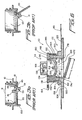
- An example of such a conventional or typical cargo air bag inflation valve assembly is disclosed within US-A-5,082,244. As disclosed within FIGURE 1, which corresponds in part to FIGURE 5 of the noted patent, the air bag is disclosed at 10 and is seen to comprise first and second oppositely disclosed sheets or
plies inflatable bladder 22 interposed therebetween. An air baginflation valve assembly 28 comprises aflange portion 34 which is welded to an interior portion of theplastic bladder 22, and atubular valve body 30 which passes through a hole provided within thesheet 24 so as to effectively define a fixture external of theair bag 10 for facilitating inflation of theinternal bladder 22 with compressed air. Thevalve body 30 has apassageway 32 defined therethrough, and a valve stem 44 is located within thepassageway 32. The lower end portion of the valve stem 44 comprises avalve closure plate 46 which has anannular portion 48 which is adapted to be seated upon avalve seat member 36 of thevalve body 30. Aspring 50 normally biases the valve stem 44 to its CLOSED position, and the valve stem 44 is movable to its OPENED position when a force is imposed upon theend 52 of the valve stem 44 which is disposed opposite thevalve closure plate 46. Aninflation mechanism 54 includes amain body portion 56 within which there is provided an internally threadedportion 68 for threaded engagement with an air hose, not shown, by means of which compressed air can be supplied for inflating thebladder 22 through means of an axially orientedpassageway 66. Anannular member 58 is threadedly mounted upon a lower end portion of thebody portion 56 and has a plurality ofdetent balls 72 mounted thereon. Acollar member 60 is slidably mounted upon theannular member 58, and anannular portion 70 also projects axially downwardly from thebody portion 56 for engaging theupper end portion 52 of the valve stem 44. When thecollar member 60 is slidably moved downwardly with respect to theannular member 58, thedetent balls 72 are forced radially inwardly so as to effectively lock theinflation mechanism 54 upon theinflation valve assembly 28, by engaging annulardetent surface 80 defined betweeninclined surface portions bladder 22. - While the above
inflation valve assembly 28 has proven to be operationally satisfactory, it can nevertheless be appreciated that theassembly 28 does comprise a substantial number of operative components and is therefore in fact relatively complex. Another conventional or PRIOR ART filling nozzle or inflation valve assembly for use in conjunction with the filling of cargo or dunnage air bags, sacks, containers, or the like, and which is relatively simple in structure and operation, is disclosed within US-A-5,651,403. As can be appreciated from FIGURE 2, which substantially corresponds to FIGURE 1 of this patent, it is seen that the entire closure assembly 1 comprises a filling nozzle 5 with valve holder means 18 for holding or receiving aclosable valve 7, and a flangedmember 10 which includes a cylindrical ortubular portion 11 and a plate-shaped portion 12 which is adapted to be fixedly secured to the interior of the inflatable dunnage air bag or container. The filling nozzle 5 includes alower portion 47 which is snap-connected onto theflanged member 10 as at 49, and the upper portion of the filling nozzle 5, upon which theclosable valve 7 andvalve holder 18 are disposed, is pivotally mounted upon the flangedmember 10 by means of ahinge member 50. When the container or dunnage air bag is to be closed, the filling nozzle 5 sealingly engages the flangedmember 10 and is retained at such position by means of asnapping hook 30 snap-engaging a snap-connection member 10. When the container or dunnage air bag is to be inflated with compressed air, abayonet lock 37 is adapted to be mated with a gripping coupling through which compressed air may be delivered to the assembly 1. - While this system is readily appreciated to be substantially simpler in construction as compared to the first system it is nevertheless desirable to construct an inflation valve assembly which simplifies the overall structure of the assembly still further. In addition, it is also desirable to utilize a suitable implement in conjunction with the valve assembly which not only readily facilitates the inflation of the dunnage air bag, sack, container, or the like, but likewise facilitates the deflation of the dunnage air bag, sack, container, or the like, so as to not only efficiently secure cargo, but in addition, to efficiently enable the unloading of the cargo from the particular cargo holds of the particular truck, airplane, ship, or railroad transportation facility. These operational requirements seem to have been met by means of still another conventional or PRIOR ART air valve mechanism for an inflatable device which is disclosed within US-A-6,138,711.
- As disclosed within FIGURES 3a and 3b, which substantially correspond to FIGURES 3 and 4 of this patent, the air valve mechanism comprises a
valve block 10 which is seen to include anupper body portion 11, alower body portion 13, and a radially outwardly extending annularmounting flange member 12 interposed between the upper andlower body portions annular flange member 14 is also interposed between the upper andlower body portions positioning portion 141 is integral with one side of theflange member 14 for mounting avalve flap 20 thereon. Thevalve flap 20 comprises a deformable rubber flap which is mounted within thelower body portion 13 beneath the radially inwardly extendingflange member 14 and includes afolding groove 23 which effectively divides thevalve flap 20 into a fixed flap portion mounted upon the mounting or positioningportion 141 by means of afastening device 40, and a free flap portion which is movable between OPEN and CLOSED positions as seen in FIGURES 3b and 3a, respectively. A pair of locatingplates 131 project downwardly from substantially diametrically opposite sides of thelower body portion 13, and it is noted that the diametrical or chordal extent or distance defined between the locatingplates 131 is less than the diametrical extent of thevalve flap 20. Accordingly, when thevalve flap 20 is moved by compressed air from the CLOSED position to the OPENED position, it must deform in order to pass beyond the locatingplates 131. In a similar manner, in order to move thevalve flap 20 from the OPENED position back to its CLOSED position, thevalve flap 20 is necessarily provided with afinger rod 21 so as to again cause deformation of thevalve flap 20 and pull the same beyond the locatingplates 131. It can therefore be appreciated that while the valve mechanism of Lung-Pa appears to be operatively satisfactory, potential is present for the jamming of thevalve flap 20 within the mechanism. In addition, the valve mechanism of Lung-Pa obviously does not lend itself to automatic inflation and deflation operational modes or techniques in view of the need for operator assistance in moving thevalve flap 20 from the OPENED position to the CLOSED position. - A need therefore exists in the art for a new and improved cargo air bag inflation and deflation system which is relatively simple in structure, and which facilitates both the automatic inflation and deflation of the cargo or dunnage air bag so as to efficiently enable the securing of loaded cargo within cargo holds as well as to efficiently enable the unloading of the secured cargo from the cargo holds.
- Accordingly, it is an object of the present invention to provide a new and improved cargo or dunnage air bag inflation and deflation system for use in conjunction with the securing of cargo loads within transportation facility cargo holds as well as the unloading of the secured cargo loads from the cargo holds of the transportation facility.
- Another object of the present invention is to provide a new and improved cargo or dunnage air bag inflation and deflation system, for use in conjunction with the securing of cargo loads within transportation facility cargo holds as well as the unloading of the secured cargo loads from the cargo holds of the transportation facility, wherein the new and improved system overcomes the various operational disadvantages and drawbacks characteristic of PRIOR ART dunnage or air bag inflation systems.
- An additional object of the present invention is to provide a new and improved cargo or dunnage air bag inflation and deflation system, for use in conjunction with the securing of cargo loads within transportation facility cargo holds as well as the unloading of the secured cargo loads from the cargo holds of the transportation facility, wherein the system is relative simple in structure.
- A further object of the present invention is to provide a new and improved cargo or dunnage air bag inflation and deflation system, for use in conjunction with the securing of cargo loads within transportation facility cargo holds as well as the unloading of the secured cargo loads from the cargo holds of the transportation facility, wherein the system embodies simplified valving structure.
- A last object of the present invention is to provide a new and improved cargo or dunnage air bag inflation and deflation system, for use in conjunction with the securing of cargo loads within transportation facility cargo holds as well as the unloading of the secured cargo loads from the cargo holds of the transportation facility, wherein the system embodies simplified valving structure as well as an air gun which is uniquely adapted to be operatively and fluidically mated with such valving structure so as to be capable of achieving both inflation of the cargo or dunnage air bag as well as deflation of the cargo or dunnage air bag.
- The foregoing and other objectives are achieved in accordance with the teachings and principles of the present invention through the provision of a new and improved cargo or dunnage air bag inflation and deflation system which comprises an inflation-deflation valve member, and a cap-type plug member. The valve member comprises a flapper or check valve element pivotally mounted within a lower portion of the valve member so as to permit inflation or deflation of the cargo or dunnage air bag when the flapper or check valve element is moved away from its valve seat, and to substantially maintain the cargo or dunnage air bag in its inflated state when the flapper or check valve element is effectively seated upon its valve seat. The cap-type plug member is removably mounted upon the inflation-deflation valve member so as to effectively close and seal the valve assembly when the cap-type plug assembly is mounted upon the valve member so as to be disposed at its CLOSED state, and which effectively uncovers the valve member when the cap-type plug member is disposed at its OPENED state. More particularly, when the cap-type plug member is disposed at its OPENED state so as to effectively uncover the valve member, a gun-type implement is able to be structurally and fluidically connected to the valve assembly so as to either enable or facilitate the inflation of the cargo or dunnage air bag or to enable or facilitate the deflation of the cargo or dunnage air bag depending upon whether a fill-nozzle end portion of the gun is operatively and fluidically connected to the valve member or whether an exhaust-nozzle end portion of the gun is operatively and fluidically connected to the valve member.
- Particular embodiments in accordance with this invention will now be described with reference to the accompanying drawings; in which:-
- FIGURE 1 is a cross-sectional view of a first PRIOR ART cargo air bag inflation valve assembly as mounted upon an inflatable cargo air bag;
- FIGURE 2 is a cross-sectional view of a second PRIOR ART cargo air bag inflation valve assembly to be mounted upon an inflatable cargo air bag;
- FIGURES 3a and 3b are cross-sectional views of a third PRIOR ART inflation valve assembly to be mounted upon an object to be inflated, wherein the valve assembly is respectively disclosed in its CLOSED and OPENED positions;
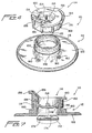
- FIGURE 4 is an exploded perspective view of a first embodiment of cargo or dunnage air bag inflation-deflation valve member and cap-type plug assembly in accordance with present invention;
- FIGURE 5 is an assembled perspective view of the cargo or dunnage air bag inflation-deflation valve member and cap-type plug assembly shown in FIGURE 4;
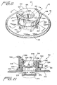
- FIGURE 6 is a cross-sectional view of the cargo or dunnage air bag inflation-deflation valve member and cap-type plug assembly shown in FIGURE 5 as taken along the lines 6-6 of FIGURE 5 and, in addition, shown as mounted upon an interior portion of an inflatable cargo or dunnage air bag;
- FIGURE 7 is a cross-sectional view of the cargo or dunnage air bag inflation-deflation valve member and cap-type plug assembly shown in FIGURE 5 as taken along the lines 7-7 of FIGURE 5;
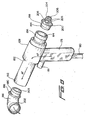
- FIGURE 8 is an exploded perspective view of an inflation-deflation gun for operative use in conjunction with the cargo or dunnage air bag inflation-deflation valve member shown in FIGURES 4-7;
- FIGURE 9 is a side elevational view of the inflation-deflation gun schematically illustrating the operative use of each operative end of the gun in conjunction with a cargo or dunnage air bag inflation-deflation valve member shown in FIGURES 4-7;
- FIGURE 10 is a cross-sectional view, of the inflation-deflation gun schematically illustrating the operative use of each operative end of the gun in con-junction with a cargo or dunnage air bag inflation-deflation valve member shown in FIGURES 4-7, as taken along the lines 10-10 of FIGURE 9; and,
- FIGURE 11 is a cross-sectional view similar to that of FIGURE 7 showing, however, a second embodiment of a cargo or dunnage air bag inflation-deflation valve member and cap-type plug assembly in accordance with the present invention.
-
- Referring now to the drawings, and more particularly to FIGURES 4-7 thereof, a first embodiment of a new and improved cargo or dunnage air bag inflation-deflation valve member and cap-type plug assembly, constructed in accordance with the principles and teachings of the present invention and showing the cooperative parts thereof, is disclosed and is generally indicated by the
reference character 110. As can be readily appreciated, the cargo or dunnage air bag inflation-deflation valve member and cap-type plug assembly 110 is seen to comprise an inflation-deflation valve member 112, and a cap-type plug orclosure member 114, which is adapted to be mounted, in a repetitively removable manner, upon the inflation-deflation valve member 112 when neither an inflation or deflation operative cycle is being performed in connection with an inflatable cargo ordunnage air bag 116, which is shown in FIGURE 6, so as to sealingly close the inflatable cargo ordunnage air bag 116 under such non-inflation, non-deflation operative conditions. The inflation-deflation valve member 112 is seen to comprise an axially central, vertically upstanding tubular housing orwall portion 118 defining an axially extendingair passageway 120, and a radially outwardly extendingflange portion 122 integrally connected to the lowermost end portion of the tubular wall orhousing portion 118 as can best be appreciated from FIGURES 6 and 7. More particularly, a wall portion of theair bag 116 is provided with a hole oraperture 124, and the outer orexternal surface 126 of the radially outwardly extendingflange portion 122 of the inflation-deflation valve member 112 is adapted to be heat-sealed or welded to an interior surface portion of the inflatable bladder of theair bag 116 such that the tubular housing orwall portion 118 of the inflation-deflation valve member 112 projects outwardly through the hole oraperture 124 so as to be externally accessible to a source of high-pressure or compressed air which is operatively connected to agun 128 as is disclosed within FIGURES 8-10 and as will be discussed further hereinafter. - As has been noted hereinbefore, the cap-type plug or
closure member 114 is adapted to be mounted, in a repetitively removable manner, upon the inflation-deflation valve member 112 when neither an inflation or deflation operative cycle is being performed in connection with the inflatable cargo ordunnage air bag 116 so as to sealingly close the inflatable cargo ordunnage air bag 116 under such non-inflation, non-deflation operative conditions. More particularly, the cap-type plug orclosure member 114 is fabricated from a suitable rubber, thermoplastic, or other relatively compliant material, and it is seen that the cap-type plug orclosure member 114 comprises an upper, horizontally disposed, annularly configuredplanar support member 130, a first radially outer, circumferentially extendingperipheral wall 132 projecting axially downwardly from an undersurface portion of the upperplanar support member 130 located near the outer peripheral edge portion thereof, and a second radially inner, circumferentially extendingwall 134 which also projects axially downwardly from an undersurface portion of the upperplanar support member 130 located near the inner peripheral edge portion thereof. The second radially inner, circumferentially extendingwall 134 is radially spaced from the first radially outer, circumferentially extendingperipheral wall 132 so as to define anannular space 136 there-between, and in this manner, as can best be appreciated from FIGURES 6 and 7, when the cap-type plug orclosure member 114 is mounted upon the inflation-deflation valve member 112, the upwardly extending tubular housing orwall portion 118 of the inflation-deflation valve member 112 will be disposed and accommodated within theannular space 136 defined between the first radially outer and second radially inner circumferentially extending walls 132,134. - The inner peripheral, circumferentially extending surface portion of the second radially inner circumferentially extending
wall 134 defines a central recess orpocket 138 which extends axially downwardly from the upperplanar support member 130, and a substantially horizontally extendingstructural member 140, having a substantially circular cross-sectional configuration, is integrally formed upon a lower end portion of the second radially inner, circumferentially extendingwall 134. In this manner, the substantially horizontally extendingstructural member 140 serves as a bottom end wall which closes the recess orpocket 138 and thereby effectively completes the structure of the cap-type plug member 114. In order to assist in securing the cap-type plug orclosure member 114 upon the upper end portion of the tubular housing orwall portion 118 of the inflation-deflation valve member 112 in a snap-fitting manner, it is seen further, from FIGURES 4,6, and 7, that the outer wall surface of the tubular housing orwall portion 118 of the inflation-deflation valve member 112 is integrally provided with a circumferentially extending convex band orridge member 142, while the inner wall surface of the first radially outer, circumferentially extendingperipheral wall 132 of the cap-type plug orclosure member 114 is correspondingly provided with a circumferentially extendingconcave recess 144 for accommodating theridge member 142. In a similar manner, the inner peripheral wall surface of the tubular housing orwall portion 118 of the inflation-deflation valve member 112 is provided with a circumferentially extending concave recessedregion 146, and the external peripheral wall surface of the second radially inner, circumferentially extendingwall 134 of the cap-type plug orclosure member 114 is correspondingly provided with a circumferentially extending convex band orridge member 148 which is adapted to be accommodated within the recessedregion 146 when the cap-type plug orclosure member 114 is snap-fitted upon the inflation-deflation valve member 112. It is to be further appreciated that the substantially horizontally extendingstructural member 140 comprises an axially central, horizontally disposedplanar section 150 which is integrally connected to the second radially inner, circumferentially extendingwall 134 of the cap-type plug orclosure member 114 by means of an upwardly inclined annular wall portion 152. - In addition, a plurality of radially extending
rib members 154 structurally reinforce the annular wall portion 152, and it is particularly noted that the lower radially inner ends of therib members 154 are connected to theplanar section 150, while the upper radially outer ends of therib members 154 are connected to the second radially inner, circumferentially extendingwall 134 at elevational levels which substantially correspond to the location of the circumferentially extending convex band orridge member 148 of the cap-type plug orclosure member 114. In this manner, when the cap-type plug orclosure member 114 is snap-fittingly mounted upon the inflation-deflation valve member 112, and the interior of the cargo ordunnage air bag 116 is inflated, the air pressure within the inflated cargo ordunnage air bag 116 will act upon the undersurface portion of the axially central, horizontally disposedplanar section 150 of the cap-type plug orclosure member 114 so as to tend to cause or bias the axially central, horizontally disposedplanar section 150 upwardly. Correspondingly, forces will be transmitted by means of therib members 154 toward the second radially inner, circumferentially extendingwall 134 of the cap-type plug orclosure member 114 so as to effectively ensure the tight disposition and sealing of the circumferentially extending convex band orridge member 148 of the cap-type plug orclosure member 114 within the circumferentially extending concave recessedregion 146 of the inflation-deflation valve member 112. - It is further noted that, in connection with the snap-fitted mounting of the cap-type plug or
closure member 114 upon the inflation-deflation valve member 112, a substantially upstanding handle or hand-graspingmember 156, having a substantially triangularly configured cross-sectional configuration, as best seen from FIGURE 7, is integrally formed upon the upperplanar support member 130, and that the handle ormember 156 further comprises a radially outwardly projectinglip portion 158. It can be appreciated that the member or handle 156, particularly in conjunction with thelip portion 158, facilitates the upward lifting, and the downward depression, of the cap-type plug orclosure member 114 with respect to its seated position upon the inflation-deflation valve member 112 during repetitive dismounting or disassembly, and mounting or assembly, respectively, of the cap-type plug orclosure member 114 from or upon the inflation-deflation valve member 112. When the cap-type plug orclosure member 114 is dismounted or disassembled from the inflation-deflation valve member 112, it is nevertheless desirable to maintain the cap-type plug orclosure member 114 attached to the inflation-deflation valve member 112 such that the cap-type plug orclosure member 114 does not actually become separated from the inflation-deflation valve member 112 whereby the cap-type plug orclosure member 114 could then be misplaced or lost. - Accordingly, it is further seen that the inflation-
deflation valve member 112 is provided with a plurality of circumferentially spacedlug members 160 which are integrally formed at the junction of the inner periphery of theflange portion 122 and the lower end portion of the tubular housing orwall portion 118, and that one of thelug members 160 is provided with a through-aperture 162. Atether member 164 is integrally provided upon the upperplanar support member 130 and is attached thereto at aproximal end portion 166 which is located substantially diametrically opposite the handle or hand-graspingmember 156. The free or distal end portion of thetether member 164 is provided with a substantially triangularly-configuredhead section 168 which is adapted to be inserted through theaperture 162 defined within thenoted lug member 160. Accordingly, when the cap-type plug orclosure member 114 is to be initially mounted or assembled upon the inflation-deflation valve member 112, thehead section 168 of thetether member 164 is inserted through theaperture 162 of thenoted lug member 160 whereby thebase portion 170 of thehead section 168, after being compressed and forced through theaperture 162, will effectively prevent passage of thetriangular head section 168 back through theaperture 162 in a reverse direction or retrograde manner. Therefore, the cap-type plug orclosure member 114 is securely attached to the inflation-deflation valve member 112 and can be subsequently sealingly positioned upon the inflation-deflation valve member 112 when desired, that is, for example, either for cargo or dunnage air bag storage purposes, or subsequent to the completion of an air bag inflation procedure, operation, or cycle in order to maintain the cargo or dunnage air bag in its inflated condition or state. - Continuing further, and in accordance with another unique feature of the present invention, a flapper valve or
check valve element 172 is operatively associated with the lower end of theair passageway 120 defined within and extending axially through the vertically upstanding tubular housing orwall portion 118 of the inflation-deflation valve member 112. More particularly, the flapper valve orcheck valve element 172 comprises, in effect, a plate-type member which is integrally formed with the inflation-deflation valve member 112, and as can best be appreciated from FIGURES 6 and 7, a proximal end portion of the flapper valve orcheck valve element 172 is integrally connected to a lower, inner peripheral region of the vertically upstanding tubular housing orwall portion 118 by means of a pair of arcuately spaced living hinge mechanisms 174,174. As noted within FIGURE 6, theair passageway 120, defined within and extending axially through the vertically upstanding tubular housing orwall portion 118 of the inflation-deflation valve member 112, has a predetermined diametrical extent D, and the f lapper valve orcheck valve component 172 likewise has a predetermined diametrical or cross-sectional extent L wherein the diametrical or cross-sectional extent L of the flapper valve orcheck valve element 172 is slightly greater than the diametrical extent D of theair passageway 120. - The reason for this is that when the interior of the dunnage or
cargo air bag 116 is pressurized and inflated, it is desirable that the air pressure within the dunnage orcargo air bag 116 will tend to close the flapper valve orcheck valve element 172 with respect to the lower end portion of theair passageway 120 such that the flapper valve orcheck valve element 172 is positioned upon itsvalve seat 176 which is defined by means of the annular wall portion of the inflation-deflation valve member 112 which is formed at the juncture of the vertically upstanding tubular housing orwall portion 118 and the radially outwardly extendingflange portion 122. In this manner, the seating of the flapper valve orcheck valve element 172 upon itsvalve seat 176 effectively prevents any massive leakage of the pressurized air out from the interior portion of the dunnage or cargo air bag prior to the operator having the opportunity to sealingly close theair passageway 120 of the inflation-deflation valve member 112 by sealingly mounting the cap-type plug orclosure member 114 thereon. However, it is likewise desirable that the flapper valve orcheck valve element 172 does not become trapped or otherwise stuck within the lower end portion of theair passageway 120 so as to always be capable of freely performing its valving functions in connection with the inflation of the dunnage orcargo air bag 116, the deflation of the dunnage orcargo air bag 116, and the maintenance of the inflated state or condition of the dunnage orcargo air bag 116. Accordingly, it can be appreciated that when the flapper valve orcheck valve element 172 is moved toward its CLOSED position, the outer periphery of the flapper valve orcheck valve element 172 will abut or be disposed in contact with thevalve seat portion 176 of the inflation-deflation valve member 112, however, the f lapper valve orcheck valve element 172 will not actually enter or be disposed internally within the lower end portion of theair passageway 120. - With reference now being made to FIGURES 8-10, the new and improved air gun implement 128, as constructed in accordance with the principles and teachings of the present invention, and which is adapted to be used in conjunction with the inflation-
deflation valve member 112 for achieving inflation and deflation of the dunnage orcargo air bag 116, will now be discussed and described. More particularly, the air gun implement 128 may comprise, for example, a VORTEC Model 2100/BPS type gun which is available from ITW VORTEC in Cincinnati, OHIO, USA, and is seen to include anupstanding handle 178 to which anair hose 180 is operatively connected. Atrigger member 181 is reciprocably mounted upon the upper end portion of thehandle 178 so as to control a suitable valve mechanism, not shown, between a CLOSED state at which the incoming pressurized air fromhose 180 is effectively prevented from flowing through the air gun implement 128, and an OPENED state at which the incoming pressurized air fromhose 180 is permitted to flow through the air gun implement 128. Abarrel section 182 of the air gun implement 128 is integrally mounted atop thehandle 178, and an air flow-throughpassageway 184, having a predetermined internal diametrical extent, is defined within thebarrel section 182 so as to permit air flow therethrough as shown by means of the fluid flow arrows AF illustrated in FIGURE 8. - As viewed in FIGURES 8-10, the left open end portion of the
barrel section 182 of the air gun implement 128 is adapted to have a tubularfill nozzle member 186 fixedly mounted therein, while the right open end portion of thebarrel section 182 of the air gun implement 128 is similarly adapted to have a tubularexhaust nozzle member 188 fixedly mounted therein. Theupstream end portion 190 of thefill nozzle member 186, as considered in the direction of air flow as denoted by means of the fluid flow arrows AF, has a predetermined external diametrical extent which is slightly smaller than the predetermined internal diametrical extent of the barrel flow-throughpassageway 184 so as to permit the same to be disposed internally within thedownstream end portion 192 of thebarrel section 182, while thedownstream end portion 194 of theexhaust nozzle member 188 similarly has a predetermined external diametrical extent which is likewise slightly smaller than the predetermined internal diametrical extent of the barrel flow-throughpassageway 184 so as to permit the same to be disposed internally within theupstream end portion 196 of thebarrel section 182. Theupstream end portion 190 of thefill nozzle member 186 is provided with anannular flange 198 which is adapted to abut, engage, and be seated upon the open end wall of thedownstream end portion 192 of thebarrel section 182 when thefill nozzle member 186 is mounted within thedownstream end portion 192 of thebarrel section 182, as can best be appreciated from FIGURES 8 and 10, and thedownstream end portion 194 of theexhaust nozzle member 188 is similarly provided with anannular flange 200 which is likewise adapted to abut, engage, and be seated upon the open end wall of theupstream end portion 196 of thebarrel section 182 when theexhaust nozzle member 188 is mounted within theupstream end portion 196 of thebarrel section 182. - In a similar manner, the
downstream end portion 202 of thefill nozzle member 186 has a predetermined internal diametrical extent which is slightly larger than the external diametrical extent of the vertically upstanding tubular housing orwall portion 118 of the inflation-deflation valve member 112 so as to permit the air gun implement 128, and in particular, thefill nozzle member 186 thereof, to be fluidically connected to the inflation-deflation valve member 112 as illustrated within the left side portion of FIGURE 10. As a result of such fluidic connection defined between thefill nozzle member 186 of the air gun implement 128 and the inflation-deflation valve member 112, and upon actuation of thetrigger member 181 of the air gun implement 128, high-pressure air fromair hose 180 will flow through thepassageway 184 of the air gun implement 128 and thepassageway 203 of thefill nozzle member 186 thereby impinging upon the flapper valve orcheck valve element 172 so as to thereby unseat the same from itsvalve seat 176 and permit inflation of the dunnage orcargo air bag 116. Alternatively, it is likewise noted that theupstream end portion 204 of theexhaust nozzle member 188 has a predetermined external diametrical extent which is slightly less than the internal diametrical extent of the vertically upstanding tubular housing orwall portion 118 of the inflation-deflation valve member 112 so as to permit the air gun implement 128, and in particular, theexhaust nozzle member 188 thereof, to be fluidically connected to the inflation-deflation valve member 112 as illustrated within the right side portion of FIGURE 10. - More particularly, the
upstream end portion 204 of theexhaust nozzle member 188 comprises anosepiece 206 which is integrally connected to theannular flange member 200 by means of a plurality of circumferentially spacedspiderlegs 208. consequently, when it is desired to deflate the dunnage orcargo air bag 116, theexhaust nozzle member 188 is mated with, inserted into, and internally disposed within the inflation-deflation valve member 112. As can best be appreciated from FIGURES 9 and 10, thenosepiece 206 will therefore engage the flapper valve orcheck valve member 172 thereby unseating thevalve element 172, and maintaining the same away, from itsvalve seat 176 so as to establish fluidic communication between the interior of the dunnage orcargo air bag 116 and thepassageway 210 of theexhaust nozzle member 188 as well as with the flow-throughpassageway 184 of the air gun implement 128. Accordingly, upon actuation of thetrigger member 181 of the air gun implement 128, high pressure air fromair hose 180 will flow throughpassageway 184 of air gun implement 128, as well as throughpassageway 203 offill nozzle member 186, so as to exhaust to atmosphere, while at the same time, or concomitantly therewith, air will be sucked out of or exhausted from the interior of the dunnage orcargo air bag 116 so as to likewise be exhausted past flapper valve orcheck valve element 172, between spider-legs 208, throughexhaust nozzle passageway 10,gun barrel passageway 184, and fillnozzle passageway 203. - With reference lastly being made to FIGURE 11, a second embodiment of a new and improved cargo or dunnage air bag inflation-deflation valve member and cap-type plug assembly, constructed in accordance with the principles and teachings of the present invention and showing the cooperative parts thereof, is disclosed and is generally indicated by the
reference character 310. It is to be noted that the structural components comprising the second embodiment of the dunnage or cargo air bag inflation-deflation valve member and cap-type plug assembly 310 are substantially the same as those of the first embodiment of the dunnage or cargo air bag inflation-deflation valve member and cap-type plug assembly 110, except as will be noted hereinafter, and therefore, a detailed description of such second embodiment of the dunnage or cargo air bag inflation-deflation valve member and cap-type plug assembly 310 will be omitted for brevity purposes. Accordingly, it is further noted in conjunction with the description of the second embodiment of the dunnage or cargo air bag inflation-deflation valve member and cap-type plug assembly 310 that the various structural components thereof, which are similar to the various structural components of the first embodiment of the dunnage or cargo air bag inflation-deflation valve member and cap-type plug assembly 110 are denoted by means of corresponding reference characters except that they are within the 300 series. More particularly, as can be seen from FIGURE 11, the only significant difference between the second embodiment of the dunnage or cargo air bag inflation-deflation valve member and cap-type plug assembly 310 and that of the first embodiment of the dunnage or cargo air bag inflation-deflation valve member and cap-type plug assembly 110 resides in the fact that in lieu of the cap-type plug orclosure member 114 being connected to the inflation-deflation valve member 112 by means oftether 164, anannular ring member 333 is adapted to be mounted upon the external peripheral surface of the vertically upstanding tubular housing orwall portion 318 of the inflation-deflation valve member 312, and an external peripheral portion of the radially outer, circumferentially extendingperipheral wall 332 of the cap-type plug orclosure member 314 is integrally connected to theannular ring member 333 by means of aliving hinge element 335. In this manner, as was the case of the first embodiment of the dunnage or cargo air bag inflation-deflation valve member and cap-type plug assembly 110, the cap-type plug orclosure member 314 is securely fixed to the inflation-deflation valve member 312 so as not to be separated therefrom and thereby misplaced or lost. - Thus, it may be seen that in accordance with the principles and teachings of the present invention, there has been developed a new and improved inflation-deflation valve member and cap-type plug assembly wherein the same comprises a relatively simple flapper valve or check valve element incorporated within the inflation-deflation valve member. In addition, a new and improved air gun implement has a fill nozzle member and an exhaust valve member operatively mounted upon opposite ends thereof so as to be able to fluidically and structurally interact with the flapper valve or check valve element and thereby achieve inflation and deflation of the dunnage or cargo air bag.
Claims (15)
- An inflation-deflation valve member and closure member assembly for use in connection with the inflation and deflation of an inflatable container, comprising:a valve member comprising a tubular housing portion, disposed around an axis and defining an air passageway having a predetermined diametrical extent and through which air can be supplied into an inflatable container and exhausted from the inflatable container so as to respectively inflate and deflate the inflatable container, and a radially outwardly extending flange portion integrally mounted upon a lower end portion of said tubular housing portion for sealed fixation to an interior surface portion of the inflatable container such that when said radially outwardly extending flange portion is fixed to the interior surface portion of the inflatable container, said tubular housing portion of said valve member projects outwardly from the inflatable container so as to be accessible to a source of pressurized air whereby said air passageway of said tubular housing portion will be fluidically connected to the interior of the inflatable container;a valve element movably mounted upon said radially outwardly extending flange portion of said valve member and having a predetermined diametrical extent which is slightly greater than said predetermined diametrical extent of said air passageway such that when said valve element is disposed at a first CLOSED position at which said valve element substantially closes said air passageway defined within said tubular housing portion of said valve member so as to effectively prevent inflation and deflation of the inflatable container, said valve element will abut a portion of said radially outwardly extending flange portion of said valve member which defines a peripheral portion of said air passageway defined within said tubular housing portion of said valve member so as not to be capable of being disposed internally within said air passageway defined within said tubular housing portion of said valve member, and a second OPENED position at which said valve element substantially uncovers said air passageway defined within said tubular housing portion of said valve member so as to effectively permit inflation and deflation of the inflatable container; anda closure member removably mountable upon said tubular housing portion of said valve member so as to permit the passage of air through said tubular housing portion of said valve member in connection with an inflation operation and a deflation operation for the inflatable container when said closure member is dismounted from said tubular housing portion of said valve member, and to prevent the passage of air through said tubular housing portion of said valve member so as to in turn prevent the inflation and deflation of the inflatable container when said closure member is mounted upon said tubular housing portion of said valve member.
- An air gun implement for connection to a valve member of an inflatable container so as to inflate and deflate the inflatable container, comprising:an air gun having an air passageway defined therein;means for fluidically connecting said air gun to a source of pressurized air whereby pressurized air can be supplied to said air passageway;a first end of said air passageway defining first means for supplying pressurized air from said air passageway into the inflatable container so as to inflate the inflatable container; anda second end of said air passageway defining second means for exhausting air from the inflatable container into said air passageway so as to deflate the inflatable container.
- The air gun implement as set forth in claim 2, further comprising:a handle;means for attaching an air hose to said handle for supplying pressurized air from a source of pressurized air to said air gun;a barrel portion integrally attached to an upper portion of said handle;said air passageway is defined within said barrel portion;said first means for supplying pressurized air from said air passageway into the inflatable container so as to inflate the inflatable container comprises a fill nozzle fixedly mounted upon a first end of said barrel portion so as to be fluidically connected to said air passageway in order to fluidically supply pressurized air from said air hose into the inflatable container when said fill nozzle is connected to the inflatable container so as to inflate the inflatable container; andsaid second means for exhausting air from the inflatable container into said air passageway so as to deflate the inflatable container comprises an exhaust nozzle fixedly mounted upon a second end of said barrel portion so as to be fluidically connected to said air passageway in order to fluidically connect the inflatable container to said air passageway when said exhaust nozzle is connected to the inflatable container so as to deflate the inflatable container.
- In combination, an inflation-deflation valve assembly, and an air gun implement, for use in connection with the inflation and deflation of an inflatable container, comprising:a valve member having a first portion for sealed fixation to an interior surface portion of an inflatable container, a second portion for projection outwardly from the inflatable container so as to be accessible to a source of pressurized air, and a first air passageway defined within said valve member through which air can be supplied into the inflatable container and exhausted from the inflatable container so as to respectively inflate and deflate the inflatable container;an air gun having a second air passageway defined therein;means for fluidically connecting said air gun to a source of pressurized air whereby pressurized air can be supplied to said second air passageway defined within said air gun;a first end of said second air passageway defined within said air gun and connectable to said valve member for supplying pressurized air from said second air passageway of said air gun to said valve member for the introduction of pressurized air into the inflatable container so as to inflate the inflatable container; anda second end of said second air passageway defined within said air gun and connectable to said valve member for exhausting air from the inflatable container, through said valve member, and into said second air passageway of said air gun so as to deflate the inflatable container.
- The combination as set forth in claim 4, wherein:said first portion of said valve member comprises a flange portion for sealed fixation to the interior surface portion of the inflatable container; andsaid second portion of said valve member comprises a tubular housing portion disposed around an axis and defining said first air passageway within said valve member.
- The combination as set forth in claim 5, wherein said valve member further comprises:a valve element movably mounted upon said valve member between a first CLOSED position at which said valve element substantially closes said first air passageway defined within said tubular housing portion of said valve member so as to effectively prevent inflation and deflation of the inflatable container, and a second OPENED position at which said valve element substantially uncovers said first air passageway defined within said tubular housing portion of said valve member so as to effectively permit inflation and deflation of the inflatable container.
- The combination as set forth in claim 5, further comprising:a closure member removably mountable upon said tubular housing portion of said valve member so as to permit the passage of air through said tubular housing portion of said valve member in connection with an inflation operation and a deflation operation for the inflatable container when said closure member is dismounted from said tubular housing portion of said valve member, and to prevent the passage of air through said tubular housing portion of said valve member so as to in turn prevent the inflation and deflation of the inflatable container when said closure member is mounted upon said tubular housing portion of said valve. member.
- The combination as set forth in claim 6, wherein:said first air passageway defined within said tubular housing portion of said valve member has a predetermined diametrical extent; andsaid valve element has a predetermined diametrical extent which is slightly larger than said predetermined diametrical extent of said first air passageway such that when said valve element is disposed at its CLOSED position, said valve element cannot enter said first air passageway.
- The combination as set forth in claim 4, wherein said air gun further comprises:a handle;means for attaching an air hose, fluidically connected to the source of pressurized air, to said handle for supplying pressurized air from the source of pressurized air to said air gun;a barrel portion integrally attached to an upper portion of said handle and having first and second end portions;said second air passageway is defined within said barrel portion and extends between said first and second end portions thereof;a fill nozzle fixedly mounted upon said first end portion of said barrel portion for fluidic connection to said second air passageway in order to fluidically supply pressurized air from said air hose into the inflatable container when said fill nozzle is connected to the inflatable container so as to inflate the inflatable container; andan exhaust nozzle fixedly mounted upon said second end portion of said barrel portion for fluidic connection to said second air passageway in order to fluidically connect the inflatable container to said second air passageway when said exhaust nozzle is connected to the inflatable container so as to deflate the inflatable container.
- The combination as set forth in claim 9, wherein:said exhaust nozzle comprises a nosepiece for engaging said valve element when said exhaust nozzle is fluidically connected to said valve member so as to move said valve element to said OPENED position and thereby permit air from the inflatable container to be exhausted from the inflatable container.
- The assembly of claim 1 or a combination of claims 4 to 10, wherein:said valve element comprises a flapper-type valve element or a check valve element.
- The assembly or combination according to claim 11, wherein:said valve element is integrally connected to said valve member by means of living hinge structure.
- The assembly or combination according to any one of claim 1 or claims 4 to 12, further comprising:tether means for operatively connecting said closure member to said valve member so as to prevent separated loss of said closure member from said valve member when said closure member has been dismounted from said valve member.
- The assembly or a combination according to claim 1 or any one of claims 4 to 13, further comprising:living hinge means for operatively connecting said closure member to said valve member so as to prevent separated loss of said closure member from said valve member when said closure member has been dismounted from said valve member.
- The assembly or a combination according to claim 1 or any one of claims 4 to 14, further comprising:finger-grip means mounted upon said closure member for facilitating the dismounting and mounting of said closure member from and upon said valve member.
Priority Applications (1)
| Application Number | Priority Date | Filing Date | Title |
|---|---|---|---|
| EP20040029302 EP1514729A3 (en) | 2002-05-20 | 2003-05-07 | Air bag inflation/deflation system |
Applications Claiming Priority (2)
| Application Number | Priority Date | Filing Date | Title |
|---|---|---|---|
| US147894 | 2002-05-20 | ||
| US10/147,894 US7610929B2 (en) | 2002-05-20 | 2002-05-20 | Air bag inflation/ deflation system |
Related Child Applications (1)
| Application Number | Title | Priority Date | Filing Date |
|---|---|---|---|
| EP20040029302 Division EP1514729A3 (en) | 2002-05-20 | 2003-05-07 | Air bag inflation/deflation system |
Publications (1)
| Publication Number | Publication Date |
|---|---|
| EP1364833A1 true EP1364833A1 (en) | 2003-11-26 |
Family
ID=28454085
Family Applications (2)
| Application Number | Title | Priority Date | Filing Date |
|---|---|---|---|
| EP20040029302 Withdrawn EP1514729A3 (en) | 2002-05-20 | 2003-05-07 | Air bag inflation/deflation system |
| EP20030252842 Withdrawn EP1364833A1 (en) | 2002-05-20 | 2003-05-07 | Air bag inflation/deflation system |
Family Applications Before (1)
| Application Number | Title | Priority Date | Filing Date |
|---|---|---|---|
| EP20040029302 Withdrawn EP1514729A3 (en) | 2002-05-20 | 2003-05-07 | Air bag inflation/deflation system |
Country Status (10)
| Country | Link |
|---|---|
| US (1) | US7610929B2 (en) |
| EP (2) | EP1514729A3 (en) |
| JP (1) | JP2004042887A (en) |
| KR (1) | KR20030090497A (en) |
| AU (1) | AU2003204041B9 (en) |
| BR (1) | BR0300923A (en) |
| CA (1) | CA2425571A1 (en) |
| MX (1) | MXPA03004460A (en) |
| NZ (2) | NZ525528A (en) |
| TW (1) | TW565670B (en) |
Cited By (6)
| Publication number | Priority date | Publication date | Assignee | Title |
|---|---|---|---|---|
| WO2006039723A3 (en) * | 2004-10-08 | 2006-07-27 | Robert B Chaffee | Methods and apparatus for controlling air in inflatable devices |
| US8162009B2 (en) | 2006-04-04 | 2012-04-24 | Chaffee Robert B | Method and apparatus for monitoring and controlling pressure in an inflatable device |
| US8225444B2 (en) | 2001-07-10 | 2012-07-24 | Chaffee Robert B | Inflatable device forming mattresses and cushions |
| US8413278B2 (en) | 2006-04-04 | 2013-04-09 | Robert B. Chaffee | Method and apparatus for monitoring and controlling pressure in an inflatable device |
| WO2017144888A1 (en) * | 2016-02-24 | 2017-08-31 | Vikoma International Limited | Inflatable booms |
| CN107444244A (en) * | 2016-05-30 | 2017-12-08 | 鹿星艺 | A kind of unmanned transport vehicle |
Families Citing this family (28)
| Publication number | Priority date | Publication date | Assignee | Title |
|---|---|---|---|---|
| US7273065B1 (en) | 2005-08-12 | 2007-09-25 | Robbins James A | Inflation/deflation valve for cargo dunnage |
| US20080304987A1 (en) * | 2007-06-05 | 2008-12-11 | Chi-Yuan Chang | Bladder-Inflating Structure |
| US20090139582A1 (en) * | 2007-11-30 | 2009-06-04 | Franta Thomas B | Inflation valve assembly |
| WO2009109910A1 (en) * | 2008-03-04 | 2009-09-11 | Stopak (Pty) Ltd | Inflation device |
| CA2761693A1 (en) * | 2009-05-12 | 2010-11-18 | Stopak (Pty) Ltd. | Inflation device |
| US7770612B1 (en) * | 2009-09-04 | 2010-08-10 | Jimmy Earle Brown | Pressure-actuated air gun |
| US8235632B2 (en) | 2010-05-14 | 2012-08-07 | Illinois Tool Works Inc. | Cargo bag valve deflector |
| DE102011053197B4 (en) * | 2011-09-01 | 2019-08-01 | Airbus Operations Gmbh | Supply channel with inflatable projection element for an aircraft, method for extending and retracting the inflatable projection element and use of a supply channel in an aircraft |
| US10562436B2 (en) | 2013-07-30 | 2020-02-18 | Signode Industrial Group Llc | Portable dunnage bag inflator |
| US9505334B2 (en) | 2013-08-05 | 2016-11-29 | Signode Industrial Group Llc | Valve |
| WO2015051394A1 (en) * | 2013-10-08 | 2015-04-16 | Sea To Summit Pty Ltd | Improved valve for inflatable devices |
| DE102014210810B4 (en) * | 2014-06-05 | 2021-12-02 | Robert Bosch Gmbh | Control device for an electromagnetic actuator for a restraint |
| US9969315B2 (en) | 2014-06-30 | 2018-05-15 | Signode Industrial Group Llc | Pneumatic inflator for automatically inflating inflatable articles to a desired pressure |
| CN105365231B (en) * | 2014-08-22 | 2017-05-17 | 大捷达实业(深圳)有限公司 | Tire repairing liquid tank |
| CN104595537B (en) * | 2014-12-24 | 2017-01-18 | 宁波五马实业有限公司 | Tire valve connector capable of being rapidly installed |
| US10144096B2 (en) * | 2016-03-22 | 2018-12-04 | General Electric Company | Gas turbine in situ inflatable bladders for on-wing repair |
| CN106621091A (en) * | 2017-03-09 | 2017-05-10 | 陈如意 | Multifunctional inflatable air bag |
| US10400951B2 (en) | 2017-05-02 | 2019-09-03 | Signode Industrial Group Llc | Dunnage bag suspender |
| US10697555B2 (en) | 2017-08-17 | 2020-06-30 | Signode Industrial Group Llc | Valve |
| CN111492163B (en) | 2017-10-27 | 2022-05-13 | 斯托巴克印度私人有限公司 | Inflation valve |
| CN108189966B (en) * | 2017-11-20 | 2019-10-11 | 沪东中华造船(集团)有限公司 | A kind of pipe end face protection sealing plate fast dismounting device and its application method |
| EP3849788B1 (en) | 2018-09-12 | 2023-06-07 | Signode India Limited | Inflator with automatic shut-off functionality |
| USD904461S1 (en) | 2018-09-21 | 2020-12-08 | Stopak India Pvt. Ltd. | Inflator |
| CN111306233B (en) * | 2018-12-11 | 2022-06-07 | 宇通客车股份有限公司 | Air spring and vehicle |
| USD928841S1 (en) | 2019-04-10 | 2021-08-24 | Signode Industrial Group Llc | Inflator |
| USD943636S1 (en) | 2020-05-26 | 2022-02-15 | Signode Industrial Group Llc | Inflator |
| CN111623175B (en) * | 2020-06-10 | 2021-10-12 | 杭州亿通塑胶实业有限公司 | PVC tubular product convenient to install |
| CN114216064A (en) * | 2021-11-19 | 2022-03-22 | 华能新疆青河风力发电有限公司 | Pipeline leak protection oil collecting equipment |
Citations (5)
| Publication number | Priority date | Publication date | Assignee | Title |
|---|---|---|---|---|
| US5119842A (en) * | 1991-07-23 | 1992-06-09 | Jaw Horng Chang | Nozzle for inflatable objects |
| US5343889A (en) * | 1992-09-21 | 1994-09-06 | Jaw Horng Chang | Nozzle for inflatable objects |
| US5566728A (en) * | 1993-10-22 | 1996-10-22 | Spanset Inter Ag | Method and apparatus for use with inflatable stowage pads for transport purposes |
| EP0987194A1 (en) * | 1996-03-06 | 2000-03-22 | Ronald L. Voller | Apparatus and method for inflating and deflating a dunnage bag |
| US6138711A (en) * | 1999-07-07 | 2000-10-31 | Ho Lee Co., Ltd. | Air valve for an inflatable device |
Family Cites Families (22)
| Publication number | Priority date | Publication date | Assignee | Title |
|---|---|---|---|---|
| US1315955A (en) * | 1919-09-16 | Valve for inelatimra bodies | ||
| US679519A (en) * | 1900-12-31 | 1901-07-30 | Lyman T Smith | Valve for pneumatic tires. |
| US2677388A (en) * | 1951-08-30 | 1954-05-04 | Gen Tire & Rubber Co | Rubber inflation valve with interlocking detachable closure |
| US2688995A (en) * | 1951-12-21 | 1954-09-14 | Edmund L Wagoner | Liquid container for beer or the like |
| US3458079A (en) * | 1967-08-14 | 1969-07-29 | Bennett Ind Inc | Sealing arrangement for plastic container |
| US3692208A (en) * | 1970-06-22 | 1972-09-19 | Dart Ind Inc | Closure for open-mouthed containers or tubular vessels |
| US4004614A (en) * | 1975-08-01 | 1977-01-25 | Halkey-Roberts Corporation | Tether for captive plug of inflation device |
| US4114230A (en) * | 1976-12-20 | 1978-09-19 | The Scott & Fetzer Company | Deflator-inflator attachment |
| NZ201884A (en) | 1982-09-10 | 1986-01-24 | Addington Engineering Ltd | Suction/blower device using compressed air blast |
| US5308336A (en) * | 1982-09-28 | 1994-05-03 | Applied Medical Resources | Seal protection mechanism |
| US4640435A (en) * | 1986-01-23 | 1987-02-03 | Sun Coast Plastics, Inc. | Plastic closure for beverage container |
| US4865456A (en) * | 1987-10-01 | 1989-09-12 | Gretag Aktiengesellschaft | Measuring head |
| JPH01141267A (en) * | 1987-11-26 | 1989-06-02 | Ckd Controls Ltd | Motion direction converting device |
| US4823831A (en) * | 1988-10-04 | 1989-04-25 | Jaw Horng Chang | Nozzle for inflatable objects |
| US5082244A (en) | 1990-12-28 | 1992-01-21 | Shippers Paper Products Company | Cargo air bag inflation valve and inflator combination |
| WO1994006695A1 (en) | 1992-09-14 | 1994-03-31 | Bates Ventil Sække Co. A/S | A closure for sacks, bags or the like containers |
| US5626257A (en) * | 1995-11-08 | 1997-05-06 | Carlson; Leonard E. | Paint bladder |
| US5660512A (en) | 1996-01-11 | 1997-08-26 | Elze; Helmut Richard | Apparatus to protect perishable products during transport |
| US5862843A (en) * | 1996-08-12 | 1999-01-26 | Corbitt, Iii; Newsome E. | Inflator/deflator nozzle |
| JPH11268771A (en) * | 1998-01-23 | 1999-10-05 | Tomematsu Abe | Air dunnage bag |
| JPH11292099A (en) * | 1998-04-03 | 1999-10-26 | Kiyoshi Takaura | Inlet-/outlet-opening closure for airtight bag |
| JP2002053155A (en) * | 2000-08-08 | 2002-02-19 | Daiichi Kasei Kogyo Kk | Cap for bottle |
-
2002
- 2002-05-20 US US10/147,894 patent/US7610929B2/en not_active Expired - Fee Related
-
2003
- 2003-03-06 TW TW92105059A patent/TW565670B/en not_active IP Right Cessation
- 2003-03-31 BR BR0300923A patent/BR0300923A/en not_active Application Discontinuation
- 2003-04-15 CA CA 2425571 patent/CA2425571A1/en not_active Abandoned
- 2003-04-15 KR KR10-2003-0023802A patent/KR20030090497A/en not_active Application Discontinuation
- 2003-04-30 NZ NZ525528A patent/NZ525528A/en not_active IP Right Cessation
- 2003-05-02 AU AU2003204041A patent/AU2003204041B9/en not_active Ceased
- 2003-05-07 EP EP20040029302 patent/EP1514729A3/en not_active Withdrawn
- 2003-05-07 EP EP20030252842 patent/EP1364833A1/en not_active Withdrawn
- 2003-05-20 MX MXPA03004460A patent/MXPA03004460A/en unknown
- 2003-05-20 JP JP2003142110A patent/JP2004042887A/en active Pending
- 2003-07-22 NZ NZ527143A patent/NZ527143A/en not_active IP Right Cessation
Patent Citations (5)
| Publication number | Priority date | Publication date | Assignee | Title |
|---|---|---|---|---|
| US5119842A (en) * | 1991-07-23 | 1992-06-09 | Jaw Horng Chang | Nozzle for inflatable objects |
| US5343889A (en) * | 1992-09-21 | 1994-09-06 | Jaw Horng Chang | Nozzle for inflatable objects |
| US5566728A (en) * | 1993-10-22 | 1996-10-22 | Spanset Inter Ag | Method and apparatus for use with inflatable stowage pads for transport purposes |
| EP0987194A1 (en) * | 1996-03-06 | 2000-03-22 | Ronald L. Voller | Apparatus and method for inflating and deflating a dunnage bag |
| US6138711A (en) * | 1999-07-07 | 2000-10-31 | Ho Lee Co., Ltd. | Air valve for an inflatable device |
Cited By (8)
| Publication number | Priority date | Publication date | Assignee | Title |
|---|---|---|---|---|
| US8225444B2 (en) | 2001-07-10 | 2012-07-24 | Chaffee Robert B | Inflatable device forming mattresses and cushions |
| WO2006039723A3 (en) * | 2004-10-08 | 2006-07-27 | Robert B Chaffee | Methods and apparatus for controlling air in inflatable devices |
| US8162009B2 (en) | 2006-04-04 | 2012-04-24 | Chaffee Robert B | Method and apparatus for monitoring and controlling pressure in an inflatable device |
| US8413278B2 (en) | 2006-04-04 | 2013-04-09 | Robert B. Chaffee | Method and apparatus for monitoring and controlling pressure in an inflatable device |
| US8839474B2 (en) | 2006-04-04 | 2014-09-23 | Robert B. Chaffee | Method and apparatus for monitoring and controlling pressure in an inflatable device |
| US9289073B2 (en) | 2006-04-04 | 2016-03-22 | Robert B. Chaffee | Method and apparatus for monitoring and controlling pressure in an inflatable device |
| WO2017144888A1 (en) * | 2016-02-24 | 2017-08-31 | Vikoma International Limited | Inflatable booms |
| CN107444244A (en) * | 2016-05-30 | 2017-12-08 | 鹿星艺 | A kind of unmanned transport vehicle |
Also Published As
| Publication number | Publication date |
|---|---|
| US20030213518A1 (en) | 2003-11-20 |
| KR20030090497A (en) | 2003-11-28 |
| CA2425571A1 (en) | 2003-11-20 |
| AU2003204041B2 (en) | 2005-02-10 |
| NZ525528A (en) | 2003-09-26 |
| EP1514729A2 (en) | 2005-03-16 |
| AU2003204041B9 (en) | 2007-03-29 |
| MXPA03004460A (en) | 2003-11-27 |
| TW565670B (en) | 2003-12-11 |
| US7610929B2 (en) | 2009-11-03 |
| NZ527143A (en) | 2003-09-26 |
| EP1514729A3 (en) | 2005-06-29 |
| AU2003204041A1 (en) | 2003-12-04 |
| TW200307105A (en) | 2003-12-01 |
| JP2004042887A (en) | 2004-02-12 |
| BR0300923A (en) | 2004-08-17 |
Similar Documents
| Publication | Publication Date | Title |
|---|---|---|
| US7610929B2 (en) | Air bag inflation/ deflation system | |
| US7434594B1 (en) | Inflation/deflation valve for cargo dunnage | |
| US6823905B1 (en) | Inflation valve assembly for a dunnage or cargo air bag | |
| US7066442B2 (en) | Valve | |
| US7913724B2 (en) | Inflation device | |
| US5806572A (en) | Apparatus for inflating and deflating a dunnage bag | |
| US8297321B2 (en) | Device for sealing and inflating inflatable object | |
| US20100147416A1 (en) | Device for sealing and inflating inflatable object | |
| US7793687B2 (en) | Inflation/deflation adaptor assembly for inflating and deflating inflatable cargo dunnage bags | |
| US10408360B2 (en) | Inflation valve | |
| US20120114505A1 (en) | Inflation device | |
| US6676042B2 (en) | Airbag inflation nozzle assembly | |
| AU2005201624B2 (en) | Air bag inflation/deflation system | |
| JP3484541B2 (en) | Valves for inflation of bags, bags and other similar containers | |
| EP2399728B1 (en) | Device for sealing and inflating inflatable object | |
| US20200041030A1 (en) | Inflator head | |
| AU7878698A (en) | Apparatus for inflating and deflating a dunnage bag | |
| WO2008099237A1 (en) | Inflation device | |
| MXPA98006693A (en) | Apparatus for inflating and deflating a bag for esti |
Legal Events
| Date | Code | Title | Description |
|---|---|---|---|
| PUAI | Public reference made under article 153(3) epc to a published international application that has entered the european phase |
Free format text: ORIGINAL CODE: 0009012 |
|
| AK | Designated contracting states |
Kind code of ref document: A1 Designated state(s): AT BE BG CH CY CZ DE DK EE ES FI FR GB GR HU IE IT LI LU MC NL PT RO SE SI SK TR |
|
| AX | Request for extension of the european patent |
Extension state: AL LT LV MK |
|
| 17P | Request for examination filed |
Effective date: 20040514 |
|
| AKX | Designation fees paid |
Designated state(s): AT BE BG CH CY CZ DE DK EE ES FI FR GB GR HU IE IT LI LU MC NL PT RO SE SI SK TR |
|
| 17Q | First examination report despatched |
Effective date: 20040825 |
|
| GRAP | Despatch of communication of intention to grant a patent |
Free format text: ORIGINAL CODE: EPIDOSNIGR1 |
|
| STAA | Information on the status of an ep patent application or granted ep patent |
Free format text: STATUS: THE APPLICATION IS DEEMED TO BE WITHDRAWN |
|
| 18D | Application deemed to be withdrawn |
Effective date: 20051018 |