EP1364755A1 - Exoskeleton for a human arm, especially for spatial applications - Google Patents
Exoskeleton for a human arm, especially for spatial applications Download PDFInfo
- Publication number
- EP1364755A1 EP1364755A1 EP03291149A EP03291149A EP1364755A1 EP 1364755 A1 EP1364755 A1 EP 1364755A1 EP 03291149 A EP03291149 A EP 03291149A EP 03291149 A EP03291149 A EP 03291149A EP 1364755 A1 EP1364755 A1 EP 1364755A1
- Authority
- EP
- European Patent Office
- Prior art keywords
- exoskeleton
- articulation
- joint
- joints
- arm
- Prior art date
- Legal status (The legal status is an assumption and is not a legal conclusion. Google has not performed a legal analysis and makes no representation as to the accuracy of the status listed.)
- Granted
Links
Images


Classifications
-
- A—HUMAN NECESSITIES
- A61—MEDICAL OR VETERINARY SCIENCE; HYGIENE
- A61H—PHYSICAL THERAPY APPARATUS, e.g. DEVICES FOR LOCATING OR STIMULATING REFLEX POINTS IN THE BODY; ARTIFICIAL RESPIRATION; MASSAGE; BATHING DEVICES FOR SPECIAL THERAPEUTIC OR HYGIENIC PURPOSES OR SPECIFIC PARTS OF THE BODY
- A61H1/00—Apparatus for passive exercising; Vibrating apparatus ; Chiropractic devices, e.g. body impacting devices, external devices for briefly extending or aligning unbroken bones
- A61H1/02—Stretching or bending or torsioning apparatus for exercising
- A61H1/0274—Stretching or bending or torsioning apparatus for exercising for the upper limbs
- A61H1/0277—Elbow
-
- A—HUMAN NECESSITIES
- A61—MEDICAL OR VETERINARY SCIENCE; HYGIENE
- A61H—PHYSICAL THERAPY APPARATUS, e.g. DEVICES FOR LOCATING OR STIMULATING REFLEX POINTS IN THE BODY; ARTIFICIAL RESPIRATION; MASSAGE; BATHING DEVICES FOR SPECIAL THERAPEUTIC OR HYGIENIC PURPOSES OR SPECIFIC PARTS OF THE BODY
- A61H1/00—Apparatus for passive exercising; Vibrating apparatus ; Chiropractic devices, e.g. body impacting devices, external devices for briefly extending or aligning unbroken bones
- A61H1/02—Stretching or bending or torsioning apparatus for exercising
- A61H1/0274—Stretching or bending or torsioning apparatus for exercising for the upper limbs
- A61H1/0281—Shoulder
-
- A—HUMAN NECESSITIES
- A63—SPORTS; GAMES; AMUSEMENTS
- A63B—APPARATUS FOR PHYSICAL TRAINING, GYMNASTICS, SWIMMING, CLIMBING, OR FENCING; BALL GAMES; TRAINING EQUIPMENT
- A63B21/00—Exercising apparatus for developing or strengthening the muscles or joints of the body by working against a counterforce, with or without measuring devices
- A63B21/00178—Exercising apparatus for developing or strengthening the muscles or joints of the body by working against a counterforce, with or without measuring devices for active exercising, the apparatus being also usable for passive exercising
-
- A—HUMAN NECESSITIES
- A63—SPORTS; GAMES; AMUSEMENTS
- A63B—APPARATUS FOR PHYSICAL TRAINING, GYMNASTICS, SWIMMING, CLIMBING, OR FENCING; BALL GAMES; TRAINING EQUIPMENT
- A63B21/00—Exercising apparatus for developing or strengthening the muscles or joints of the body by working against a counterforce, with or without measuring devices
- A63B21/00181—Exercising apparatus for developing or strengthening the muscles or joints of the body by working against a counterforce, with or without measuring devices comprising additional means assisting the user to overcome part of the resisting force, i.e. assisted-active exercising
-
- A—HUMAN NECESSITIES
- A63—SPORTS; GAMES; AMUSEMENTS
- A63B—APPARATUS FOR PHYSICAL TRAINING, GYMNASTICS, SWIMMING, CLIMBING, OR FENCING; BALL GAMES; TRAINING EQUIPMENT
- A63B21/00—Exercising apparatus for developing or strengthening the muscles or joints of the body by working against a counterforce, with or without measuring devices
- A63B21/40—Interfaces with the user related to strength training; Details thereof
- A63B21/4001—Arrangements for attaching the exercising apparatus to the user's body, e.g. belts, shoes or gloves specially adapted therefor
- A63B21/4017—Arrangements for attaching the exercising apparatus to the user's body, e.g. belts, shoes or gloves specially adapted therefor to the upper limbs
- A63B21/4019—Arrangements for attaching the exercising apparatus to the user's body, e.g. belts, shoes or gloves specially adapted therefor to the upper limbs to the hand
-
- A—HUMAN NECESSITIES
- A63—SPORTS; GAMES; AMUSEMENTS
- A63B—APPARATUS FOR PHYSICAL TRAINING, GYMNASTICS, SWIMMING, CLIMBING, OR FENCING; BALL GAMES; TRAINING EQUIPMENT
- A63B21/00—Exercising apparatus for developing or strengthening the muscles or joints of the body by working against a counterforce, with or without measuring devices
- A63B21/40—Interfaces with the user related to strength training; Details thereof
- A63B21/4001—Arrangements for attaching the exercising apparatus to the user's body, e.g. belts, shoes or gloves specially adapted therefor
- A63B21/4017—Arrangements for attaching the exercising apparatus to the user's body, e.g. belts, shoes or gloves specially adapted therefor to the upper limbs
- A63B21/4021—Arrangements for attaching the exercising apparatus to the user's body, e.g. belts, shoes or gloves specially adapted therefor to the upper limbs to the wrist
-
- A—HUMAN NECESSITIES
- A63—SPORTS; GAMES; AMUSEMENTS
- A63B—APPARATUS FOR PHYSICAL TRAINING, GYMNASTICS, SWIMMING, CLIMBING, OR FENCING; BALL GAMES; TRAINING EQUIPMENT
- A63B21/00—Exercising apparatus for developing or strengthening the muscles or joints of the body by working against a counterforce, with or without measuring devices
- A63B21/40—Interfaces with the user related to strength training; Details thereof
- A63B21/4023—Interfaces with the user related to strength training; Details thereof the user operating the resistance directly, without additional interface
- A63B21/4025—Resistance devices worn on the user's body
-
- A—HUMAN NECESSITIES
- A63—SPORTS; GAMES; AMUSEMENTS
- A63B—APPARATUS FOR PHYSICAL TRAINING, GYMNASTICS, SWIMMING, CLIMBING, OR FENCING; BALL GAMES; TRAINING EQUIPMENT
- A63B21/00—Exercising apparatus for developing or strengthening the muscles or joints of the body by working against a counterforce, with or without measuring devices
- A63B21/40—Interfaces with the user related to strength training; Details thereof
- A63B21/4041—Interfaces with the user related to strength training; Details thereof characterised by the movements of the interface
- A63B21/4047—Pivoting movement
-
- A—HUMAN NECESSITIES
- A63—SPORTS; GAMES; AMUSEMENTS
- A63B—APPARATUS FOR PHYSICAL TRAINING, GYMNASTICS, SWIMMING, CLIMBING, OR FENCING; BALL GAMES; TRAINING EQUIPMENT
- A63B23/00—Exercising apparatus specially adapted for particular parts of the body
- A63B23/035—Exercising apparatus specially adapted for particular parts of the body for limbs, i.e. upper or lower limbs, e.g. simultaneously
- A63B23/03508—For a single arm or leg
-
- A—HUMAN NECESSITIES
- A63—SPORTS; GAMES; AMUSEMENTS
- A63B—APPARATUS FOR PHYSICAL TRAINING, GYMNASTICS, SWIMMING, CLIMBING, OR FENCING; BALL GAMES; TRAINING EQUIPMENT
- A63B23/00—Exercising apparatus specially adapted for particular parts of the body
- A63B23/035—Exercising apparatus specially adapted for particular parts of the body for limbs, i.e. upper or lower limbs, e.g. simultaneously
- A63B23/12—Exercising apparatus specially adapted for particular parts of the body for limbs, i.e. upper or lower limbs, e.g. simultaneously for upper limbs or related muscles, e.g. chest, upper back or shoulder muscles
- A63B23/1209—Involving a bending of elbow and shoulder joints simultaneously
-
- A—HUMAN NECESSITIES
- A63—SPORTS; GAMES; AMUSEMENTS
- A63B—APPARATUS FOR PHYSICAL TRAINING, GYMNASTICS, SWIMMING, CLIMBING, OR FENCING; BALL GAMES; TRAINING EQUIPMENT
- A63B23/00—Exercising apparatus specially adapted for particular parts of the body
- A63B23/035—Exercising apparatus specially adapted for particular parts of the body for limbs, i.e. upper or lower limbs, e.g. simultaneously
- A63B23/12—Exercising apparatus specially adapted for particular parts of the body for limbs, i.e. upper or lower limbs, e.g. simultaneously for upper limbs or related muscles, e.g. chest, upper back or shoulder muscles
- A63B23/1245—Primarily by articulating the shoulder joint
- A63B23/1263—Rotation about an axis passing through both shoulders, e.g. cross-country skiing-type arm movements
-
- B—PERFORMING OPERATIONS; TRANSPORTING
- B25—HAND TOOLS; PORTABLE POWER-DRIVEN TOOLS; MANIPULATORS
- B25J—MANIPULATORS; CHAMBERS PROVIDED WITH MANIPULATION DEVICES
- B25J9/00—Programme-controlled manipulators
- B25J9/0006—Exoskeletons, i.e. resembling a human figure
-
- A—HUMAN NECESSITIES
- A63—SPORTS; GAMES; AMUSEMENTS
- A63B—APPARATUS FOR PHYSICAL TRAINING, GYMNASTICS, SWIMMING, CLIMBING, OR FENCING; BALL GAMES; TRAINING EQUIPMENT
- A63B2208/00—Characteristics or parameters related to the user or player
- A63B2208/12—Characteristics or parameters related to the user or player specially adapted for children
Definitions
- the invention relates to an exoskeleton for a human arm.
- Exoskeleton is a term originally used in biology for designate the external support envelope of an animal.
- arthropods have an external chitin exoskeleton instead of a skeleton internal.
- the term has also been associated with devices structural intended to be tied around members of people.
- the human arm exoskeletons must overcoming a main problem, namely the imitation of the kinematics of complex human shoulder, elbow and wrist joints.
- the difficulty in imitation results from the fact that these joints are tightly enveloped, with their axes of rotation moving with the posture changing arm.
- the exoskeletons according to the state of the art have endeavored to approach the problem of the shoulder by the implementation of a mechanism that rests on the back top of the human shoulder. The imperfections of this approach can be found in the clutter and the mass of the mechanism. This one also weighs on the arm. In what concerning the wrist, equally massive solutions have been used.
- US Patent 4,575,297 A (Hans Richter) describes a robot comprising a chest plate, an upper arm member, a limb lower arm having finger and thumb units in which the human limbs are inserted.
- a human operator to whom these members of robot are attached, sits on a support structure such as a mobile chair.
- the robot members, their lengths, the joints between the members and the common axes correspond to those of the operator human.
- Each joint is associated with a motor sensor device hydraulic.
- the robotic shoulder part is limited to movements around two axes. Another axis allows flexion or elbow extension. An axe parallel to the axis of the forearm allows rotation of the forearm.
- an articulated connection which is parallel to the articulated articulation of the elbow, provides the means for human wrist movement.
- exoskeleton mechanism taught by the aforementioned patent copies the normal kinematics of a human arm.
- Each actuated joint is controlled by hydraulic cylinders, which are directly mounted alongside joints.
- the range of movements allowed is relatively limited. In particular, a movement without repercussions is not possible.
- American patent US 5 967580 A (Mark E. Rosheim) relates to a pair of connected joints and means of force generation for their use in slave robotic systems.
- the patent relates to an anthropomorphic mechanical manipulator, providing certain possibilities of a human thorax and possibilities of movement similar to the chest, shoulder, arm, wrist and hands of a human.
- the kinematic structure of the robot described in the The aforementioned patent resembles the kinematic structure of a human arm. It follows that we want to provide a mechanical manipulator resembling the thorax upper human and arm, and can be provided with possibilities of movements substantially equivalent to those of the human thorax and arm higher.
- a mechanical structure provides the means to engage the hands of a operator.
- a counterpart mechanism can be used as an exoskeleton to control the slave robot, but is not optimized for this use in as such.
- Both mechanisms are equivalent to the human upper limb structure in kinematics terms (limb and joint parameters).
- Each axis of rotation is directly controlled by linear current motors continued. Only a very limited range of normal human movements arm can be covered with the exoskeleton mechanism described. As indicated above, force feedback is only possible on hand human, this characteristic being the main object of this patent.
- the base of the kinematic chain is fixed on the operator's back and not on the chest. Exoskeleton movement can only be influenced by passive electric brakes, which can only be used for attenuate the normal movements of the human arm.
- Kinematics is limited to only five degrees of freedom.
- the shoulder belt movements such as wrist movements, do not are never discernible or controllable.
- Each axis is actuated directly by a DC motor device, which is mounted near an axis joint joint appropriate. Due to its very kinematic structure simplified, many of the components are to be considered to be rules.
- the base of the exoskeleton is attached to an upper part of the back of the operator.
- the invention aims, at the same time, to overcome the drawbacks of the devices of known art, some of which have just been recalled, and which respond to needs which are felt, and which have also been recalled.
- the invention sets for its object an exoskeleton for a human arm having, in particular, all the degrees of freedom thereof, which is light, portable, as it does not limit operator movements, adaptable to a large percentage of the population, without significant changes, which allows to feel all the movements of the human arm, does not limit the range of natural movements, and be comfortable.
- an exoskeleton according to the invention has the following essential characteristics:
- the arm exoskeleton resembles, as regards its support base, half of an armor top. It has two plates rigid chest (front and back) and an articulated sleeve. The plates of chest are fixed to the operator's chest by straps or any other means appropriate equivalents.
- the front plate serves as a structural base for a chain joints that articulate the sleeve. It provides a fixed reference for everything exoskeleton movement.
- the backplate supports motors which move the neck joints. Motors and joints are connected by a series of flexible tendons which activate them.
- the exoskeleton according to the invention has several characteristics advantageous techniques.
- each posture of human joints can be determined unequivocally by the corresponding posture of the kinematic chain exoskeleton.
- the base of the exoskeleton is a part of the human body.
- the exoskeleton can be designed as a portable system that provides more flexibility for general operator movements.
- a portable exoskeleton controller Through the use of a portable exoskeleton controller, remote controls weightlessness, or at least in micro-gravity, are very simplified because that no resulting force on the operator's body can cause a movement away from the command station. For example, if we uses joysticks, such as joysticks Anglo-Saxon terminology), these create forces against the body of the astronaut, who push him away from the controller. Therefore, it must be attached in a suitable place and its operational possibilities are thus limited.
- a second important characteristic is that all of the joints activated in the exoskeleton (i.e. not passive) are controlled by tendon cable transmissions.
- tendon cable transmissions usually uses electrical controls directly mounted on the exoskeleton. These provisions make the exoskeleton bulky, heavy and require a large number of control units precisely for be able to accommodate a heavy weight.
- the use of cable tendons according to the invention makes it possible to place the control units on a rear plate of the exoskeleton. The weight of the control elements is therefore borne by the thorax. The result is an extremely light arm which can be controlled by smaller controls.
- a third important characteristic relates to adaptation possible exoskeleton according to the invention to different human subjects.
- its specific structural characteristics which will be detailed below allow the possible adaptation of the master arm to practically any which human subject (range of percentages mentioned above).
- the required adjustments to fit the exoskeleton can be performed while carrying it and are typically limited to tightening two screws or equivalent members, as will be also shown below.
- the main object of the invention is therefore an arm exoskeleton intended to acquire data representative of movements of the joints of arm of a human operator using measurement sensors and to apply in feedback to said articulations of forces and / or couples using units activation associated with at least part of said joints, characterized in that it comprises a first device having the shape of a sleeve, intended to be threaded on at least one of said arms, so as to form a kinematic chain of joints arranged parallel to said joints arm, said device comprising a first subset called exoskeleton shoulder comprising a first determined number of associated joints at the shoulder joints of said operator, a second subset said elbow exoskeleton comprising a second determined number of joints associated with the elbow joints of said operator and a third subset called wrist exoskeleton including a third determined number of joints associated with wrist joints of said operator, in that said activation units are controlled by flexible tendons running along said subsets, said first to third subsets being mechanically dissociated so as to be capable of being individually controlled by said flexible
- the invention also relates to the application of an arm exoskeleton to the remote control of a humanoid robot working outside a space space station equipped with artificial arms and performing tasks under the command of a human operator, said arm exoskeleton being threaded on at least one of its arms, said robot receiving data forcing execution movements in one-to-one relation with movements of said arm and transmitting so-called feedback data forcing the execution of movements of all or part of said joints of said arm exoskeleton and causing corresponding movements of said arm.
- the "go” data consist of orders transmitted to the robot for activate it, according to particular movements that the operator prints to the exoskeleton.
- the robot reproduces the movements of the exoskeleton. In sense reverse, it sends data that will be called “feedback” allowing the operator “physically feeling” the forces and couples undergone by the robot, and not just “visually”, for example by following tasks executed by the robot on a display screen.
- This feedback on the operator is very important, because it allows, for example, to precisely dose the aforementioned forces and couples exerted by the remote-controlled robot.
- FIGS. 1A and 1B schematically illustrate an example of an exoskeleton of an EXB arm according to a preferred embodiment of the invention and its main components.
- the exoskeleton EXB arm is shown carried by an operator U in front view (Figure 1A) and partial rear view ( Figure 1B), respectively.
- the EXB actual arm exoskeleton comprises three main subassemblies: a subset of one wrist, elbow subset 2 and subset shoulder 3, respectively. These three subsets, 1 to 3, are dedicated to the detection of relative movements of the wrist P , the elbow C and the shoulder E of an operator U and to the actuation of the associated joints. They form a sleeve threaded on one of its arms, for example the right arm Bd.
- FIGS. 1A and 1B the sub-assemblies, 1 to 3, of the exoskeleton of arm EXB are shown threaded on the right arm Bd of the operator U , because it is assumed that the latter is right-handed.
- the device according to the invention is in no way limited to this characteristic. It can just as easily be threaded onto the left arm Bg of the operator U or, on both arms, without departing from the scope of the invention.
- the aforementioned kinematic chain is fixed to a glove 5 slipped on one or both hands, M of the operator, in this case on his right hand.
- the aforementioned kinematic chain is fixed to the thorax TH of the operator U , using a support base 4 .
- the support base 4 resembles a half of armor. It has two rigid chest plates: front 40 (Figure 1A) and back 41 ( Figure 1B).
- the chest plates, 40 and 41 are fixed to the thorax TH of the operator U by straps 42, or any equivalent suitable means.
- the front plate 40 serves as a structural base for the chain of articulations of the subsets 1 to 3. It provides a fixed reference for any movement of the exoskeleton of the EXB arm .
- the various sub-assemblies, 1 to 3, of the aforementioned kinematic chain are interconnected.
- Bundles of flexible tendons 7 of the cable type actuate particular articulations associated with the sub-assemblies 1 to 3, so-called “active” articulations and are in turn actuated by Mt motors (FIG. 1B).
- flexible tendons are made up of two types separate elements; cables themselves and spiral-type sheaths guiding the cables over all or part of their lengths.
- the visible part of the bundles 7 consists essentially of the sheaths.
- a first beam leads from the back of the operator U to a pre-load unit in the shoulder sub-assembly 3 and, finally, from there along the structure to the load unit initial the elbow assembly and from there further to the wrist P.
- the second beam leads directly from the back to the joints before entering a preload unit at the base of the EXB exoskeleton.
- sensors referenced to Ca 16 , Ca 21 to Ca 23 , Ca 31 to Ca 36 , 218 and 226, have been represented in various figures annexed to the present description.
- the rear plate 41 supports the aforementioned motors Mt. As illustrated in FIG. 1B, it has been assumed that the motors Mt (not explicitly shown) were arranged inside a housing 6 fixed to the plate 41. Advantageously, DC motors are used.
- the case 6 is notably connected to the kinematic chain, and more particularly to the shoulder sub-assembly 3, by the tendon bundle 7.
- the housing 6 also includes transmission-reception circuits of data and instructions communicating directly with the robot to remote control or via an intermediate station (not shown).
- the motors Mt actuate one or more articulations of the subassemblies 1 to 3 by acting on corresponding flexible tendons of the bundle 7, in the manner which will be specified below.
- the master arm of the exoskeleton EXB has sixteen joints, and thus sixteen degrees of freedom or "DOF".
- Each axis is equipped with an angle sensor to obtain information on the angles (rotation movement around a particular axis) of articulation.
- Figure 2 illustrates an exploded set of these three mechanisms, 1 to 3, connected by a bundle of flexible tendons 7.
- the master arm is not designed to imitate the arrangement of human joints, but to connect them by an alternative kinematic chain of joints arranged above the human limb: arm Bd in the example described.
- arm Bd in the example described.
- FIGS. 5A and 5B illustrate the shoulder sub-assembly 3, in view of facing and three-quarters high, respectively.
- the head of the operator U is not shown and the bundle of flexible tendons 7 is chopped off.
- This sub-assembly 3 includes six axes of articulation, five of the so-called rotoid type and one of the so-called prismatic type.
- FIG. 5C is an isometric view illustrating, in three dimensions, the relative positions of these six axes, referenced ⁇ 31 to ⁇ 36 , for a particular posture of the elbow C of the operator U , at a given instant.
- the corresponding joints are referenced “ joint 31 " to " joint 36 ".
- the sub-assembly 3 is designed to perform the same movements as those of the human shoulder E , although the five "DOF" of the human shoulder E are simulated by a mechanism with six "DOF".
- the movement of the shoulder exoskeleton 3 is not limited, neither in amplitude nor in dexterity.
- the base of the shoulder exoskeleton 3 provides a complete base link series of the exoskeleton EXB arm and is subject to the rigid breast plate 40 which is connected around the thorax of the U TH operator using strips 42.
- the securing is carried out via a fixing piece 33, which serves as a parent link for the first articulation of the EXB exoskeleton .
- the distal end of the mechanism 3 is located at the base of the upper part of the operator BS arm U , where it is fixed by means of an airbag 30, itself surrounded by a rigid annular part 31.
- the first articulation "articulation 31" around the axis ⁇ 31 which is a rotary articulation, is activated by a pair of two tendons 731, which belong to the aforementioned "bundle No. 2".
- This articulation combines the fixing piece 33 with the first member of a link " link 31".
- the link " link 31”, which is the son link of the articulation " articulation 31” comprises a pulley 312 which is fixed on a rotary shaft 313, which is connected above ball bearings to the fixing part 33.
- the shaft 313 is also rigidly connected to a circular plate 314, which is screwed under two side walls 315 and 316.
- the shaft 322 is centered in a median zone of these side walls by means of ball bearings allowing the rotation of the link “ link 32" in its entirety around the mechanical shaft 322 and thus around of the common axis ⁇ 32 .
- the pulley 323 is rigidly fixed to the side walls and thus induces the movement of the link “ link 32" around the link " link 31", when the tendons 732 ', in their sheaths 732, pull or push.
- the articulation "articulation 33”, of prismatic type and axis ⁇ 33 is provided with a telescopic tube F (FIG. 6D) extended by a pre-tension spring SP .
- the SP spring is of the so-called strand type.
- a fixed link of the telescopic articulation " articulation 33” is constituted by a first telescopic tube 332 and is combined with a flange 326.
- a mobile link, " link 33” comprises a system of telescopic tubes F and distal ends of a telescopic flange 333 which are subject to an intermediate piece 335.
- a compression spring 334 By means of a compression spring 334, the distal telescopic flange 333 is preloaded against the telescopic flange 326. If the tendon 733 'opposes the force of the SP spring , it causes a contraction movement of the telescopic tubes along the common axis ⁇ 33 .
- the joint " joint 34” which is a passive joint of the rotoid type, combines the link " link 33" with the link "link 34". By means of the articulation "articulation 34", the link " link 34" can rotate around the axis ⁇ 34 .
- the link " link 34” comprises a shaft 341 which is connected by means of radial ball bearings to an intermediate piece 335, allowing rotation around the axis ⁇ 34 .
- the ⁇ 34 axis. is screwed onto a part 342 in the shape of a "U", which carries at the two distal ends two additional plates, 343 and 345. These plates enclose ball bearings for rotation about the axis ⁇ 35 , as well as upper plates, 344 and 346 respectively.
- the fifth articulation, " articulation 35" which is also a passive rotation articulation, the link " link 34" with the link “ link 35” allowing rotation around the axis ⁇ 35 .
- the link comprises two parts collinear with the axes of the shafts 351 and 354, which are fixed to an external ring 353 by means of fixing flanges.
- the fixing flange 352 fixes the shaft 351 on the outer ring 353, and the fixing flange 355 fixes the shaft 354 to the bottom of the ring 353, respectively.
- the two shafts pass through the ball bearings, which are held between plate 343 and upper plate 344, and plate 345 and the top plate 346, respectively.
- the articulation " articulation 36", of axis ⁇ 36 is active and is used to force a rotation of the upper part of the arm BS.
- a pair of tendons 736 ' which comes from the back of the operator U , crosses the outer ring 353 without touching it and is attached to an inner ring 362, which has the function of a hollow pulley.
- This internal ring 362, which is a member of the link " link 36" is attached to another circular ring 31, which carries airbags 30.
- the circular ring 31 is connected to the external ring 353 by means of ball bearings of small section, allowing rotation around the axis ⁇ 36 .
- the flange ring 363 is screwed onto the ring 31 and another member of the link "link 36".
- the articulation " articulation 36" which can be engaged by the tendons 736 ', allows a radial movement of the link “link 36" inside the external ring 353 and, thus, inside the link “link 35", around the sixth axis of articulation ⁇ 36 .
- FIG. 5D is an isometric view, in rear view, illustrating, in three dimensions, the pre-load system 8 with its pre-tensioning members 80 bundle tendons 7.
- the tendons which are guided inside sheaths, can be pre-tensioned by putting the outer sheath under compression.
- Figure 6C describes the general configuration in more detail of such a preload unit 8.
- Each preload unit in the EXB exoskeleton design has similar devices.
- a rigid reinforcement which establishes a fixed reference, hereinafter called CR, is used to fix screws C 1 for preloading the tendons.
- the screws C 1 are hollow and allow the tendons to pass through them, which are arbitrarily referenced 700 '.
- the sheath 700 which guides the tendons 700 ′, is intersected at the point where the preload unit is placed and the intersection ends 700a of the sheaths end on the external surface of the preload screws C 1 .
- the sheath 700 is compressed as soon as the preload screws C 1 are turned clockwise. This increased compression in the spiral sheaths 700 which surround the tendons 700 'tightens them. These tendons are threaded into the sheaths, which leads to a preload of the tendons.
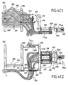
- FIG. 4A illustrates more precisely, in rear view, the sub-assembly elbow 2. This has four axes of articulation.
- FIG. 4B is an isometric view illustrating, in three dimensions, the relative positions of these four axes, ⁇ 21 to ⁇ 24 , for a particular posture of the elbow C of the operator U , at a given instant.
- the corresponding joints are referenced “ joint 21" to "joint 24".
- twin telescopic tubes, 200 and 202 respectively are shown, adjustable in length, which provide the means of adapting the length of the exoskeleton to the human upper arm BS .
- the length can be adjusted by blocking two screw members, 201 and 203 respectively, one for each tube, 200 and 202. No other adjustment is necessary.
- the first ends of the telescopic tubes, 200 and 202 are subject to an annular piece 204, surrounding the upper arm BS , that is to say above the elbow.
- this annular part is rigidly fixed to the ring 363 of the shoulder sub-assembly 3.
- the second ends are fixed to a part 205, in the shape of a horseshoe, also surrounding the upper arm BS.
- the lateral base plate 206 is rigidly mounted on the ring 205 and carries the shafts 207 which establish a part of the joint joint " joint 21".
- the median base plate 208 is also connected to the ring 205 on its proximal side, and carries another shaft 209, which, together with the shaft 207, constitute the mechanical means for rotation around the axis ⁇ 21 of l articulation " articulation 21".
- the joint adjustment unit builds the parent link for the joint " joint 21".
- the child link of this joint comprises another ring 210, having the shape of a horseshoe.
- the side plate 212 is fixed on its distal side to the proximal side of the ring 210.
- the side plate 212 is mounted on the shaft 207 by means of ball bearings which allow a radial movement.
- a pulley 213 is fixed to the side plate 212, for the actuation of the link "link 21" around the articulation " articulation 21" of axis ⁇ 21 .
- the tendons 721, which come from the bundle of cables 7 pass through the lateral base plate 206 and are fixed on the pulley 213.
- the middle plate 214 is also fixed on the proximal side of the ring 210.
- the proximal side of the middle plate 214 is mounted by means of ball bearings on the axis 209, which is collinear with the axis 207, allowing the link "link 21" to rotate around the axis ⁇ 21 .
- Two hollow tubes 215 and 216 are attached to the distal side of the ring 210. These tubes serve as a parent link to the common prismatic joint " joint 22".
- the forearm preload unit 217 is fixed to these hollow tubes 215 and 216 by means of screws.
- the tendons which cross the preload unit are not shown.
- the tendons of the cable bundle 7 entering the preload unit are shown, the outgoing tendons not being shown.
- the link "link 21" and the link “ link 22" form the joint "joint 22" which is a passive and prismatic joint.
- the link “link 22" comprises two massive rods 221 and 222, which are collinear and concentric with the hollow tubes, 215 and 216, so as to adapt exactly to the internal enclosure of the hollow tubes, and, thus, to form a telescopic tube system.
- the solid rods, 221 and 222 are movable inside the hollow tubes 215 and 216.
- the two tubes, 221 and 222 are attached to a piece 220, which is a ring section.
- This part 220 on its proximal side, connects the two massive rods and, on its distal side, is attached to a part 224, in the shape of a "T", which carries a small tree 225.
- the link "link 22" can move linearly along the axis ⁇ 22 , relative to the link "link 21".
- the preload unit carries a linear sensor 218, the movable part of which is fixed to a plate 223.
- This plate is fixed to the solid tubes, 221 and 222, by means of screws.
- link " link 22" which is a mobile link in the joint "joint 22" is at the same time the parent link for the joint "joint 23".
- FIGS. 4D1 and 4D3 describe the members of the joint " joint 23" in more detail, respectively in space, and in section “MM” in FIG. 4D2.
- the part 224 in the shape of a "T", carries a fixed shaft 225, on which are mounted two ball bearings, 226 and 227; on the lateral 226 and median 227 parts, respectively, of the part 224 in the shape of a "T".
- the mobile link on the joint "joint 23” is the link “link 23” which can perform a passive rotation around the axis ⁇ 23 of the joint " joint 23".
- This link has an external metal ring 230, which is connected to a flange piece 231 on its bottom.
- This flange piece 231 is screwed between two side plates, a median 232 and a lateral 233, respectively.
- These side plates, 233 and 232 are connected on the outside of the ball bearings, 227 and 226, respectively, thus allowing rotation around the shaft 225.
- the child link, " link 24, of the articulation” articulation 24 " which is a mobile part, comprises a rigid ring 240, which encloses an airbag 28, and a hollow pulley 241, which is attached to the proximal side of the "rigid ring 240.
- the tendons 724" which are guided along the sheaths 724, pass through the external ring 230 and are fixed to the hollow pulley 241 (as shown in FIGS. 3H1 to 3H3).
- the rigid ring 240 is centered inside the outer ring 230, by means of a ball bearing 242 of small section, which allows the rotation of the ring 240 about the axis ⁇ 24 inside the outer ring 230 This rotation is induced by the relative movement of the tendons 724 '.
- These tendons 724' are subject to the pulley 241 and to the sheaths 724 which are mechanically locked outside of the outer ring 230, by means of stop pieces 234.
- the link " link 24" can be moved around the axis ⁇ 24 of the joint " joint 24", causing pronation or supination of the forearm AB of the operator U.
- joint 22 and " joint 23”, with respective axes ⁇ 22 and ⁇ 23 , equipped with angle sensors (for example the linear sensor 218 for the ⁇ axis 22 and the angle sensor 226 for the ⁇ axis 23 , in Figures 4C1 and 4C2).
- angle sensors for example the linear sensor 218 for the ⁇ axis 22 and the angle sensor 226 for the ⁇ axis 23 , in Figures 4C1 and 4C2).
- the combined mechanism then allows precise results for the bend of the elbow C , even if the system is subjected very inaccurately.
- the system establishes a reference kinematic structure above the human elbow C , starting from the upper part of the arm BS and from the end of the forearm AB.
- Human C- elbow movements (flexion / extension and pronation / supination) can be detected and influenced without limiting the natural range of motion.
- FIG. 3A illustrates, in front view, the wrist sub-assembly 1. This has six axes of articulation, all of the rotoid type.
- FIG. 3B is an isometric view illustrating, in three dimensions, the relative positions of these six axes, ⁇ 11 to ⁇ 16 , for a particular posture of the hand M and of the wrist P of the operator U , at a given instant.
- Figures 3A and 3B are used as a reference to explain the operation of the first articulation of the wrist sub-assembly 1.
- Figures 3C1 to 3G3 further illustrate views of the disassembled mechanism. The corresponding joints are referenced “ joint 11" to " joint 16".
- the proximal end of the subassembly 1 is threaded onto the forearm AB and fixed thereon by an airbag 28 surrounded by a rigid annular piece 240, threaded on the forearm, close to the hand.
- This rigid annular part 240 is connected on its outside to the inner part of an outer ring 110, by means of a ball bearing 111 of thin section, as shown more particularly in FIGS. 3H1 to 3H3.
- the outer ring 110 can rotate around the axis ⁇ 11 , which is the axis of rotation of the joint "joint 11".
- FIG. 3A only the outer ring 110 and the inflated cushion 28 can be seen.
- the link " link 11”, which is the child link in the joint "joint 11” comprises the outer ring 110 and stop pieces 112, which are screwed onto the ring 110 to constitute a means of locking the sheaths 711 at their distal end.
- An additional member of the link “ link 11” is a fixing flange 114 which is used to fix a mechanical shaft 115 orthogonal to the external ring 110.
- a stop plate 116 is fixed under the fixing flange 114 for stop the spiral sheaths 712 at their distal end.
- the articulation "articulation 12" causes the movement of the link “ link 12” around the link “ link 11", along the axis of rotation of articulation ⁇ 12 .
- the sectional view of the joint "joint 12" in Figure 3C3 can be used to describe the joint in more detail.
- the shaft 115 carries a ball bearing 117 at its distal end, on which is fixed a base plate 120 on the external bearing surface.
- This base plate 120 constitutes a reference for the link " link 12", to which all the other parts of this link are subject.
- the pulley 124 is screwed onto the base plate 120, subjecting the tendons 712 'to the link " link 12".
- the tendons 712 ' are threaded into the stop piece 116 of the previous link and create a rotation in the link “link 12 " as soon as a relative movement between the tendons 712' and the sheaths 712 is induced by the actuation of the tendons by motors.
- two horizontal plates, 121 and 122 respectively are fixed to the base plate 120, by means of screws, as illustrated more particularly by Figures 3D1 to 3D3. These plates both carry ball bearings, 124 and 123 respectively, between which is held the mechanical shaft 131 of the joint " joint 13".
- the articulation " articulation 13" links the link " link 12" as a parent link to the child link “link 13", which turns passively around the axis ⁇ 13 .
- the base of the link “link 13” is the shaft 131, to which a cylindrical part 130 is fixed.
- This cylindrical part 130 comprises a drill, orthogonal to the cylindrical surface, which provides the means for fixing a cylindrical bundle 132 at its proximal end. Due to the rotation of the axis 131, the entire link “link 13” rotates around the axis ⁇ 13 of the joint "joint 13".
- the distal side of the cylindrical bundle 132 is fixed to a flange plate 133, which carries two horizontal plates, an upper 134 and a lower 135, respectively, as shown more particularly in FIGS. 3E1 to 3E3.
- the lower plate 135 provides a means of stopping the sheaths 714 at their distal ends.
- the plates 134 and 135 carry ball bearings which hold and center the mechanical shaft 141 between the plates 134 and 135.
- the joint " joint 14" which is an active joint, causes the rotation of the link “ link 14" around the link “ link 13", along the axis ⁇ 14 .
- the link “ link 14" has another cylindrical part 140, which is fixed on the axis 141, and has a drill orthogonal to the cylindrical surface, which fixes the proximal side of a second cylindrical bundle 143.
- a pulley 142 is in further fixed on the cylindrical part 140, to secure the tendons 714 '.
- the distal end of the cylindrical bundle 143 is held in a another cylindrical part 144, which is attached to a shaft 145.
- This shaft 145 constitutes the mechanical axis of the passive articulation " articulation 15" which connects the link “ link 14" to the " link 15", in which the link “ link 15” rotates as a child link around the link “link 14 "along the axis ⁇ 15 , as shown more particularly in FIGS. 3F1 to 3F3, and 3B.
- the shaft 145 is held between two ball bearings, which are held by two horizontal plates, an upper 151 and a lower 152, respectively, these plates being screwed onto the base plate 150 of the link " link 15".
- the distal end is fixed on a hard plastic glove 5, put on the hand M of the operator U.
- the glove 5 consists of a main envelope 50 comprising a first orifice 51 (upper in FIG. 3A) allowing the thumb to exit and one or more orifices 52 (axial) allowing a free exit of the other fingers of the hand M.
- the subassembly 1 is fixed to the envelope 50 of the glove 5 by any appropriate means (screws, etc.), via a distal part 54 associated with the hinge axis " hinge 16", of axis ⁇ 16 .
- the articulation " articulation 16" combines the link " link 15" with the distal part 54, allowing active rotation, influenced by tendons, around the axis ⁇ 16 .
- the distal part 54 is fixed to the rear of the glove 5, in which the hand M of the operator U is inserted.
- the other side of this distal part 54 is connected to a base plate 160, as shown more particularly in FIGS. 3G1 to 3G3.
- This base plate 160 is held on a second plate 161 to fix a shaft 162 orthogonal to the surface of the parts.
- This shaft 162 carries a ball bearing on its distal side, to which the base plate 150 of the " link 15" is attached.
- a pulley 153 which is directly mounted on the base plate 150 fixes the tendons 716 ', which come from the sheaths 716.
- a stop plate 163 which is attached to the base plate of the link "link 16"
- any relative movement of the tendons 716 'against the sheaths 716 induces a rotation of the "link 16" around the axis ⁇ 16 , relative to the link "link 15".
- the mobility of the handle sub-assembly can be detailed as follows:
- the three joints " joint 13” to " joint 15”, with axes ⁇ 13 to ⁇ 15 are joints of a type known as the rotoid.
- the joints " joint 13” and “ joint 15”, with axes ⁇ 13 and ⁇ 15 are purely passive, the joint " joint 14", with axis ⁇ 14 , is active and controlled by one of the pairs of flexible tendons of the bundle 7, referenced 714 '.
- the passive joints have been integrated into the subassembly 1 to provide unimpeded movement of the human wrist P during the robot's remote control operations (not shown).
- this mechanism forms a pantograph.
- the wrist abduction or adduction P can be controlled by activating the joint "joint 14", of axis ⁇ 14 , and resulting movements in the passive joints. If the tendons 714 'actuate the articulation " articulation 14" towards small articulation angles, an abduction of the wrist articulation P is imposed. As soon as the tendons 714 ′ control the articulation " articulation 14" towards high articulation angles, an adduction of the wrist articulation P is imposed.
- joints 12 and “joint 16”, with axes ⁇ 12 and ⁇ 16 are both of the active type. They are used to detect and impose the flexion movement on the wrist P. If, for example, the two joints rotate clockwise, the exoskeleton joint links control a flexion of the human wrist P upward and, conversely, a control in the counterclockwise direction d 'a watch, imposes a downward bending. If both joints are blocked, no wrist flexion can occur.
- all the articulations of this subassembly 1 are associated with sensors, Ca 12 to Ca 16 (FIG. 3B) which measure the angles of rotation around the corresponding axes, ⁇ 11 to ⁇ 16 .
- the data, results of these measurements, are transmitted, by any appropriate means, to reception systems located for example in the space station, or even directly in the housing 6 (FIG. 1B). It can be wired or wireless transmission (radio transmission, etc.).
- the subassembly 1 allows free movements of the wrist P , without in any way limiting the degree of mobility of the operator U.
- the drive pairs for active joints are transmitted remotely using tendon cables 7 ′, guided along the exoskeleton structure EXB, originating from Mt motors arranged on a rear chest plate 42, and transmitted to each activated joint.
- the mounting of the motors on the backside of the user U makes it possible to minimize the size and the weight of the exoskeleton master arm EXB .
- multi-strand cables typically 7x19 and diameter 1 mm. This choice minimizes the curvature friction and allows loads up to 50 Nm. efficiently transfer couples using a transmission tendons to cables, the cables must be subjected to forces so as to be pre-tensioned at half of their operating load, i.e. 25 Nm in the example described.
- Figures 6A, 6B and 6C schematically illustrate how a pair of tendons for cables, arbitrarily referenced 700 ', activates one of the active joints, of axis arbitrarily referenced ⁇ .
- a pulley, arbitrarily referenced R, coaxial with the axis ⁇ , is rotated about this axis by a loop formed by the pair of tendons 700 '.
- the axis of the pulley R is integral with a first part which is assumed to be fixed, arbitrarily referenced A 1 .
- a second part, assumed to be mobile, arbitrarily referenced A 2 is rotated about the axis ⁇ by the pulley R.
- FIG. 6A the two parts A 1 and A 2 are shown in the extension of one another: state referenced I. If a torque is printed on the pulley R (in the counterclockwise direction of a shown in the example: arrow f ), via the pair of tendons 700 ′, this will be rotated around the axis ⁇ and the part A 2 will follow this rotational movement: state referenced II (FIG. 6B ). The moving part, now referenced A ′ 2 , is in position orthogonal to the part A 1 .
- the tendons 700 ′ are guided on the exoskeleton EXB (FIG. 1A) by sheaths in which they slide, arbitrarily referenced 700.
- the guide length can be modified as a function of the tendon length 700 ′.
- Figure 6C describes in more detail the mechanical units included along the path of a tendon, starting from a motor and ending at an activated joint.
- Figure 6C describes the general case of activation of rotational joints.
- the tendons 700 ' which are attached to the pulleys R , as described above, are guided along the spiral sheaths 700 until they reach a preload unit, which is used to stretch the tendons 700 'through the sheaths and create a preload.
- This can be achieved by shortening the length of the tendons with respect to the sheaths by turning the preload screws C 1 counterclockwise.
- This pre-tensioning system has the advantage that the activation unit does not have to be fixed to the same reference structure as the pre-load unit, and can thus be moved in space relative to to the preload unit, without loss of tension or involuntary modification of the position of the axis having turned.
- the tendons 700 ′ Passing through the preload unit, the tendons 700 ′ are guided by a sheath 700 leading to a motorization unit (engine Mt ).
- the motorization unit Mt comprises a pulley ME which is fixed to the axis ⁇ m of the motor Mt , either directly or via a gearshift member.
- the Mt motor itself is fixed to a reference part D which is also used to stop the proximal end 700 b II of the sheaths.
- the motor Mt must drive the pulley ME in the same direction as the desired movement for the activated joint.
- FIG. 6D schematically describes the linear activation of the common prismatic joint " joint 33".
- the function of the initial preload unit is identical to the function described above with reference to FIG. 6C.
- the main difference lies in the activation unit.
- the linear articulation is actuated by a single tendon 700 ′, which is threaded in the center of the telescopic tubes F.
- These tubes F are fixed on the distal side to a stop plate H , where the distal end of the tendon 700 ′ is fixed.
- a stop plate G On the proximal side of the telescopic tubes F , another stop plate G is provided which prevents the distal end of the sheath 700 from passing inside the telescopic tubes F.
- the tendon 700 ′ can pass through the plate G and reach the interior of the sheath 700 just after having left the proximal end of the telescopic tubes F.
- a compression spring SP creates a repelling force.
- This motorization unit comprises a reference plate K on which the motor Mt is fixed and on which the proximal end 700 b II of the sheath 700 is in abutment.
- the tendon 700 'crosses the plate K and is fixed on a pulley J.
- This pulley J guides the tendon along a spiral profile, therefore with variation in radius.
- the plate H of the activation unit begins to recall the compression spring SP.
- the telescopic tubes F contract in their entirety. The release of the tendon 700 'in the opposite direction on the pulley J allows the elongation of the telescopic tubes F.
- the complete exoskeleton EXB is attached to the thorax TH of an operator U.
- Two rigid plates, 40 and 41 provide a rigid reference structure for the EXB exoskeleton .
- the two plates, 40 and 41 are attached together around the human thorax TH by means of belts 42, advantageously in self-adhesive tissue.
- the master exoskeleton arm is screwed onto the front plate with the aid of the fixing piece 33 (FIGS. 5A and 5B) and, consequently, uses the human thorax TH as a reference.
- annular air bags are used.
- FIGS. 7A and 7B illustrate, in sagittal section, the cushions inflatable ring finger for shoulder 3 (cushion 30) and elbow subsets 2 or wrist 1 (cushion 28), respectively, as also shown in the figure 2.
- the air bags, 30 and 28, are inserted into two external rigid rings, 31 and 240 respectively.
- these inflatable ring cushions can be made of silicone rubber and can be inflated using pumps which can be disconnected using quick couplers. Once inflated, the rings create a non-slip attachment between the human arm, BS or AB, and the rigid outer rings.
- the rigid external rings constitute the fixings for the elbow assembly.
- each axis is advantageously fitted with ball bearings, for example the ball bearings referenced 242 in FIG. 7B.
- ball bearings for example the ball bearings referenced 242 in FIG. 7B.
- exoskeleton arm EXB ( Figure 1A) according to the invention, it has been designed to be as light and as rigid as possible. To do this, the majority of the parts have been advantageously made from aluminum and, as far as possible, from plastics (polyvinyl chloride PVC for example).
- the large structural parts intended to enclose the arm Bd (or Bg ) of the operator U have been advantageously made from carbon fiber compounds to reduce the weight and at the same time to increase the rigidity of the rigid exoskeleton structure EXB.
- the last interface to the human arm Bd is the distal end of exoskeleton attachment to the palm of the operator U (see Figure 3A for example).
- the operator U wears a rigid palm glove 5 comprising openings 51 and 52 and fixed to the palm with self-adhesive fabric 53.
- an additional haptic interface can be used: for example a "cyber glove” or a "cyber handle”.
- the arm exoskeleton according to the invention provides, as has been recalled, many advantages, which it is useless to recall.
Abstract
Description
L'invention concerne un exosquelette pour bras humain.The invention relates to an exoskeleton for a human arm.
Elle trouve plus particulièrement application, bien que non exclusivement, dans les technologies spatiales.It finds more particularly application, although not exclusively, in space technologies.
Il est tout d'abord utile de rappeler la signification du terme "exosquelette", plus particulièrement tel qu'il est utilisé dans le cadre de l'invention.It is first useful to recall the meaning of the term "exoskeleton", more particularly as used in the context of the invention.
"Exosquelette" est un terme utilisé originellement en biologie pour désigner l'enveloppe support externe d'un animal. Par exemple, les arthropodes ont un exosquelette externe de chitine au lieu d'un squelette interne. Ces derniers temps, le terme a également été associé à des dispositifs structuraux destinés à être attachés autour de membres de personnes."Exoskeleton" is a term originally used in biology for designate the external support envelope of an animal. For example, arthropods have an external chitin exoskeleton instead of a skeleton internal. In recent times, the term has also been associated with devices structural intended to be tied around members of people.
Plus récemment encore, une nouvelle catégorie de dispositifs a été ajoutée à la famille des exosquelettes : il s'agit de mécanismes utilisés, par exemple, pour augmenter des performances d'exécution humaines, en robotique ou encore dans des interactions de réalité virtuelle. D'autres applications possibles de ces mécanismes seront détaillées ci-après.More recently, a new category of devices has been added to the exoskeleton family: these are mechanisms used, for example, to increase human execution performance, by robotics or in virtual reality interactions. other possible applications of these mechanisms will be detailed below.
Pour fixer les idées, on se placera dans ce qui suit dans le cadre de l'application préférée de l'invention, à savoir l'application aux technologies spatiales. De façon plus précise encore, on considérera le cas de la télécommande d'un robot de type humanoïde travaillant à l'extérieur d'une station spatiale, par exemple la station spatiale internationale. Il peut s'agir, dans ce cadre d'application, du robot appelé "Eurobot" qui est censé fournir un moyen très précis et adroit d'intervention pour l'inspection, la maintenance et la réparation de matériel dans l'environnement fortement hostile de l'espace. Le robot est équipé de trois bras cinématiquement semblables aux bras humains (c'est-à-dire notamment dotés de sept degrés de liberté). Pendant la majeure partie du temps, le robot est programmé pour accomplir des tâches préétablies, mais dans certains cas le robot doit être télécommandé :
- soit par des astronautes à l'intérieur de la station spatiale, ou
- soit directement par des opérateurs restés sur terre.
- either by astronauts inside the space station, or
- either directly by operators who remained on earth.
Dans les deux cas, le besoin de manipulations très précises a imposé l'utilisation de techniques dites d'immersion. Pour ce faire, l'opérateur porte des lunettes vidéo, des gants à retour de force et un ou des exosquelette(s) de bras pour ressentir les sensations du robot, c'est-à-dire celles qu'il aurait ressenties s'il avait effectué lui-même les tâches exécutées par le robot.In both cases, the need for very precise manipulations imposed the use of so-called immersion techniques. To do this, the operator wears video glasses, force feedback gloves and one or more arm exoskeletons to feel the robot’s sensations, that is, those it would have felt if he had performed the tasks performed by the robot himself.
La nécessité de créer un exosquelette compatible avec des opérateurs à terre ou des astronautes n'est pas non plus sans contraintes. Il est en effet nécessaire de réaliser un système léger (typiquement moins de 5 kg), compact et facile à porter.The need to create an exoskeleton compatible with operators ashore or astronauts is not without constraints either. It is indeed necessary to make a light system (typically less than 5 kg), compact and easy to wear.
Les exosquelettes de l'état de la technique souffrent généralement de divers inconvénients et/ou insuffisances, tels que les suivants :
- Impossibilité de ressentir tous les mouvements du bras humain et d'obtenir des forces et des couples de rétroaction, ce sans limiter la gamme normale des mouvements humains de bras. Il est notamment nécessaire d'obtenir des informations sur la position de l'épaule, du coude et du poignet.
- Difficulté de réaliser un système réellement "portable", ce qui signifie que les mouvements de l'opérateur ne devraient pas être limités pendant l'utilisation (tourner autour d'un objet, se pencher, marcher, etc.).
- Adaptation limitée, ce qui, par exemple, ne permet pas d'utiliser le même exosquelette, sans modification importante, pour un pourcentage élevé de la population masculine, typiquement dans une gamme couvrant 5% à 95%.
- Impossibility of feeling all the movements of the human arm and of obtaining forces and couples of feedback, without limiting the normal range of human arm movements. In particular, it is necessary to obtain information on the position of the shoulder, elbow and wrist.
- Difficulty creating a truly "portable" system, which means that the operator's movements should not be limited during use (turning around an object, bending over, walking, etc.).
- Limited adaptation, which, for example, does not allow the same exoskeleton to be used, without significant modification, for a high percentage of the male population, typically in a range covering 5% to 95%.
Plus précisément, les exosquelettes de bras humains doivent surmonter un problème principal, à savoir l'imitation de la cinématique des articulations humaines complexes d'épaule, de coude et de poignet. La difficulté dans l'imitation résulte du fait que ces articulations sont étroitement enveloppées, avec leurs axes de rotation se déplaçant avec la posture changeante du bras. Les exosquelettes selon l'état de la technique se sont efforcés d'approcher le problème de l'épaule par la mise oeuvre d'un mécanisme qui repose sur le dessus arrière de l'épaule humaine. Les imperfections de cette approche peuvent être trouvées dans l'encombrement et la masse du mécanisme. Celui-ci pèse d'ailleurs aussi sur le bras. En ce qui concerne le poignet, des solutions également massives ont été utilisées.Specifically, the human arm exoskeletons must overcoming a main problem, namely the imitation of the kinematics of complex human shoulder, elbow and wrist joints. The difficulty in imitation results from the fact that these joints are tightly enveloped, with their axes of rotation moving with the posture changing arm. The exoskeletons according to the state of the art have endeavored to approach the problem of the shoulder by the implementation of a mechanism that rests on the back top of the human shoulder. The imperfections of this approach can be found in the clutter and the mass of the mechanism. This one also weighs on the arm. In what concerning the wrist, equally massive solutions have been used.
En général, on constate aussi que, dans les mécanismes d'exosquelette connus, les articulations complexes de cinématique du bras humain sont simplifiées et assimilées à des articulations à un seul degré de liberté, ci-après appelé "DOF" (pour "Degree Of Freedom", selon la terminologie anglo-saxonne couramment utilisée) dans un but de simplification de la description. L'inconvénient de cette solution est que le mouvement normal du bras dit "maítre" (qui impose les actions) est perturbé et une sensation de confort, lors du fonctionnement du bras dit "esclave" (rétroaction de force) n'est pas possible.In general, we also note that, in the mechanisms of known exoskeletons, the complex kinematic joints of the arm are simplified and assimilated to single-degree joints freedom, hereinafter called "DOF" (for "Degree Of Freedom", according to Anglo-Saxon terminology commonly used) for the purpose of simplification from the description. The downside of this solution is that the normal movement of the arm called "master" (which imposes the actions) is disturbed and a feeling of comfort, during the operation of the arm called "slave" (force feedback) is Not possible.
Sans que cela soit exhaustif, on va maintenant décrire brièvement quelques solutions connues et montrer leurs limites.Without being exhaustive, we will now briefly describe some known solutions and show their limits.
Le brevet américain US 4 575 297 A (Hans Richter) décrit un robot comportant une plaque de poitrine, un membre supérieur de bras, un membre inférieur de bras ayant des unités de doigt et de pouce dans lesquelles les membres humains sont insérés. Un opérateur humain, à qui ces membres de robot sont attachés, s'assied sur une structure de soutènement telle qu'une chaise mobile. Les membres de robot, leurs longueurs, les articulations entre les membres et les axes communs correspondent à ceux de l'opérateur humain. Chaque articulation est associée à un dispositif capteur moteur hydraulique. La partie robotique d'épaule est limitée aux mouvements autour de deux axes. Un autre axe permet la flexion ou la prolongation de coude. Un axe parallèle à l'axe de l'avant-bras permet la rotation de l'avant-bras. Sur le poignet, un raccord articulé, qui est parallèle à l'articulation articulée du coude, fournit le moyen d'un mouvement humain de poignet.US Patent 4,575,297 A (Hans Richter) describes a robot comprising a chest plate, an upper arm member, a limb lower arm having finger and thumb units in which the human limbs are inserted. A human operator, to whom these members of robot are attached, sits on a support structure such as a mobile chair. The robot members, their lengths, the joints between the members and the common axes correspond to those of the operator human. Each joint is associated with a motor sensor device hydraulic. The robotic shoulder part is limited to movements around two axes. Another axis allows flexion or elbow extension. An axe parallel to the axis of the forearm allows rotation of the forearm. On the wrist, an articulated connection, which is parallel to the articulated articulation of the elbow, provides the means for human wrist movement.
Le mécanisme d'exosquelette enseigné par le brevet précité copie la cinématique normale d'un bras humain. Chaque articulation actionnée est commandée par des vérins hydrauliques, qui sont directement montés à côté des articulations. La gamme de mouvements permise est relativement limitée. En particulier, un mouvement sans répercussions n'est pas possible.The exoskeleton mechanism taught by the aforementioned patent copies the normal kinematics of a human arm. Each actuated joint is controlled by hydraulic cylinders, which are directly mounted alongside joints. The range of movements allowed is relatively limited. In particular, a movement without repercussions is not possible.
Le brevet américain US 5 967580 A (Mark E. Rosheim) est relatif à une paire d'articulations connectées et à des moyens de génération de force pour leur mise en oeuvre dans des systèmes robotiques esclaves. Le brevet est relatif à un manipulateur mécanique anthropomorphe, fournissant certaines des possibilités d'un thorax humain et des possibilités de mouvement semblables à ceux de la poitrine, de l'épaule, du bras, du poignet et des mains d'un humain. De nouveau, la structure cinématique du robot décrit dans le brevet précité ressemble à la structure cinématique d'un bras humain. Il s'ensuit que l'on désire fournir un manipulateur mécanique ressemblant au thorax humain supérieur et au bras, et pouvant être pourvu de possibilités de mouvements sensiblement équivalents à ceux du thorax et du bras humains supérieurs. Une structure mécanique fournit le moyen d'engager les mains d'un opérateur.American patent US 5 967580 A (Mark E. Rosheim) relates to a pair of connected joints and means of force generation for their use in slave robotic systems. The patent relates to an anthropomorphic mechanical manipulator, providing certain possibilities of a human thorax and possibilities of movement similar to the chest, shoulder, arm, wrist and hands of a human. Again, the kinematic structure of the robot described in the The aforementioned patent resembles the kinematic structure of a human arm. It follows that we want to provide a mechanical manipulator resembling the thorax upper human and arm, and can be provided with possibilities of movements substantially equivalent to those of the human thorax and arm higher. A mechanical structure provides the means to engage the hands of a operator.
Un mécanisme de contre-partie peut être utilisé comme exosquelette pour commander le robot esclave, mais n'est pas optimisé pour cet usage en tant que tel. On peut fournir des données de force tactile en rétroaction seulement à la partie de l'exosquelette équivalente à la main. Les deux mécanismes sont équivalents à la structure supérieure humaine de membre en termes de cinématique (paramètres des membres et des articulations). Chaque axe de rotation est directement commandé par les moteurs linéaires à courant continu. Seulement une gamme très limitée de mouvements humains normaux de bras peut être couverte avec le mécanisme d'exosquelette décrit. Comme indiqué ci-dessus, la rétroaction de force est seulement possible sur la main humaine, cette caractéristique étant l'objet principal de ce brevet.A counterpart mechanism can be used as an exoskeleton to control the slave robot, but is not optimized for this use in as such. We can provide tactile strength data in feedback only the part of the exoskeleton equivalent to the hand. Both mechanisms are equivalent to the human upper limb structure in kinematics terms (limb and joint parameters). Each axis of rotation is directly controlled by linear current motors continued. Only a very limited range of normal human movements arm can be covered with the exoskeleton mechanism described. As indicated above, force feedback is only possible on hand human, this characteristic being the main object of this patent.
Le brevet américain US 6 301526 A (Mun Sang Kim et al.) concerne à titre principal un dispositif ayant une fonction de force de rétroaction et qui est monté sur un bras humain. Celui-ci peut renvoyer en rétroaction une information de limite d'opération par l'utilisation des freins moteurs. Le dispositif principal est une configuration en chaíne, de type série, fixée sur le dos d'un opérateur. Des deuxièmes et troisièmes moyens de combinaison sont fixés au-dessus et au-dessous du coude, de même qu'un quatrième moyen de combinaison est fixé sur une partie arrière de la main. Sept axes d'exosquelette comportent des unités de frein électriques pour générer des couples. Des unités de détermination de position, ainsi que des unités de boíte de vitesse pour amplifier les couples, sont associées aux unités d'actionnement.American patent US 6 301526 A (Mun Sang Kim et al.) Relates to main title a device having a feedback force function and which is mounted on a human arm. The latter may return a operating limit information by the use of engine brakes. The device main is a chain configuration, series type, fixed on the back of a operator. Second and third combination means are fixed above and below the elbow, as well as a fourth means of jumpsuit is attached to the back of the hand. Seven axes of exoskeleton have electric brake units to generate torque. of the position determination units, as well as gearbox units to amplify the torques, are associated with the actuation units.
La base de la chaíne cinématique est fixée sur le dos de l'opérateur et pas sur la poitrine. Le mouvement d'exosquelette peut seulement être influencé par des freins électriques passifs, qui peuvent seulement être utilisés pour atténuer les mouvements normaux du bras humain. The base of the kinematic chain is fixed on the operator's back and not on the chest. Exoskeleton movement can only be influenced by passive electric brakes, which can only be used for attenuate the normal movements of the human arm.
La demande de brevet internationale WO 95/32842 A2 (AN, Bin) concerne un système qui a le même degré de liberté que le bras humain, et donc qui doit être étroitement fixé au bras humain. Le système est également cinématiquement équivalent au bras d'un opérateur. L'exosquelette est fixé sur le dos de l'opérateur et n'importe quel composant qui forme interface avec le corps humain est réglable. Il s'ensuit que n'importe quel défaut d'alignement entre l'opérateur et le système impose des contraintes cinématiques aux articulations humaines et cause un grand inconfort et une gêne pour un mouvement anatomique normal. Cette invention concerne principalement le problème de la fixation à l'opérateur, problème qui a été résolu avec les caractéristiques de conception particulières.International patent application WO 95/32842 A2 (AN, Bin) concerns a system that has the same degree of freedom as the human arm, and therefore which must be tightly attached to the human arm. The system is also kinematically equivalent to an operator's arm. The exoskeleton is fixed on the operator's back and any component that interfaces with the human body is adjustable. It follows that any misalignment between the operator and the system imposes kinematic constraints on human joints and cause great discomfort and discomfort for a normal anatomical movement. This invention mainly relates to problem of attachment to the operator, a problem which has been resolved with the special design features.
La cinématique est limitée à seulement cinq degrés de liberté. Les mouvements de la ceinture d'épaule, comme les mouvements du poignet, ne sont jamais discernables ni contrôlables. Chaque axe est actionné directement par un dispositif à moteur à courant continu, qui est monté près d'un axe commun d'articulation approprié. De par sa structure cinématique très simplifiée, beaucoup des composants sont à considérer comme devant être réglés. La base de l'exosquelette est fixée sur une partie supérieure du dos de l'opérateur.Kinematics is limited to only five degrees of freedom. The shoulder belt movements, such as wrist movements, do not are never discernible or controllable. Each axis is actuated directly by a DC motor device, which is mounted near an axis joint joint appropriate. Due to its very kinematic structure simplified, many of the components are to be considered to be rules. The base of the exoskeleton is attached to an upper part of the back of the operator.
On constate que les exosquelettes de l'art connu, dont quelques-uns viennent d'être décrits, présentent des limitations importantes et ne permettent pas de répondre entièrement aux besoins qui se font sentir, notamment pour les applications spatiales. Les exosquelettes selon l'art connu sont, pour la plupart, basés sur un mécanisme qui vise à d'imiter ou de se rapprocher au mieux de la cinématique des membres humains. Enfin, comme il ressortira de la description de l'invention qui va suivre, les mécanismes des exosquelettes selon l'art connu présentent des différences structurelles importantes avec le mécanisme mis en oeuvre dans l'invention.It is found that the exoskeletons of known art, some of which have just been described, have significant limitations and do not allow not fully meet the needs that arise, especially for space applications. Exoskeletons according to known art are, for the most, based on a mechanism that aims to imitate or come close to the better of the kinematics of human limbs. Finally, as will emerge from the description of the invention which will follow, the mechanisms of the exoskeletons according to known art present significant structural differences with the mechanism implemented in the invention.
L'invention vise, tout à la fois, à pallier les inconvénients des dispositifs de l'art connu, et dont certains viennent d'être rappelés, et à répondre aux besoins qui se font sentir, et qui ont été également rappelés.The invention aims, at the same time, to overcome the drawbacks of the devices of known art, some of which have just been recalled, and which respond to needs which are felt, and which have also been recalled.
L'invention se fixe pour but un exosquelette pour bras humain présentant, notamment, tous les degrés de liberté de celui-ci, qui soit léger, portable, car ne limitant pas les mouvements de l'opérateur, adaptable à un large pourcentage de la population, sans modifications sensibles, qui permet de ressentir tous les mouvements du bras humain, ne limite pas la gamme de mouvements naturels, et soit confortable.The invention sets for its object an exoskeleton for a human arm having, in particular, all the degrees of freedom thereof, which is light, portable, as it does not limit operator movements, adaptable to a large percentage of the population, without significant changes, which allows to feel all the movements of the human arm, does not limit the range of natural movements, and be comfortable.
Pour ce faire, et de façon pratique, la structure d'un exosquelette conforme à l'invention présente les caractéristiques essentielles suivantes :To do this, and in a practical way, the structure of an exoskeleton according to the invention has the following essential characteristics:
L'exosquelette de bras selon l'invention ressemble, en ce qui concerne sa base support, à une moitié d'un dessus d'armure. Il comporte deux plaques rigides de poitrine (avant et dos) et une manche articulée. Les plaques de poitrine sont fixées au thorax de l'opérateur par des sangles ou tous moyens appropriés équivalents. La plaque avant sert de base structurale à une chaíne d'articulations qui articule la manche. Elle fournit une référence fixe pour tout mouvement de l'exosquelette. La plaque arrière supporte des moteurs qui déplacent les articulations de manche. Les moteurs et les articulations sont reliés par une série de tendons flexibles qui les actionnent.The arm exoskeleton according to the invention resembles, as regards its support base, half of an armor top. It has two plates rigid chest (front and back) and an articulated sleeve. The plates of chest are fixed to the operator's chest by straps or any other means appropriate equivalents. The front plate serves as a structural base for a chain joints that articulate the sleeve. It provides a fixed reference for everything exoskeleton movement. The backplate supports motors which move the neck joints. Motors and joints are connected by a series of flexible tendons which activate them.
L'exosquelette selon l'invention présente plusieurs caractéristiques techniques avantageuses.The exoskeleton according to the invention has several characteristics advantageous techniques.
Selon une première caractéristique importante, la cinématique propre à un exosquelette conforme à l'invention est conçue de façon spécifique. Il n'y a aucune tentative d'imiter la cinématique de l'épaule, du coude et/ou du poignet humains. Tout au contraire, une chaíne alternative de cinématique, offrant la même liberté de mouvement, est disposée parallèlement aux articulations humaines. Cette chaíne et les articulations humaines forment une boucle cinématique fermée qui :
- pour l'épaule commence à l'attache du bras (au sternum), s'étend au-dessus des articulations et des extrémités scapulo-claviculaire et gléno-humeral et se termine au milieu de l'humérus ;
- pour le coude commence au milieu de l'humérus et se termine au milieu de l'avant-bras ; et
- pour le poignet commence au milieu de l'avant-bras et se termine au milieu de la paume de main.
- for the shoulder begins at the attachment of the arm (to the sternum), extends above the joints and the scapulo-clavicular and glenohumeral extremities and ends in the middle of the humerus;
- for the elbow begins in the middle of the humerus and ends in the middle of the forearm; and
- for the wrist begins in the middle of the forearm and ends in the middle of the palm.
Bien que la cinématique parallèle de l'exosquelette soit différente de celle du bras, chaque posture des articulations humaines peut être déterminée de façon univoque par la posture correspondante de la chaíne de cinématique d'exosquelette.Although the parallel kinematics of the exoskeleton are different from that of the arm, each posture of human joints can be determined unequivocally by the corresponding posture of the kinematic chain exoskeleton.
Les avantages apportés de cette approche sont nombreux et peuvent être résumés comme suit :
- Le poids du système n'est pas porté par le bras mais par le thorax.
- La gamme complète de mouvements d'épaule, de coude et de poignet est possible.
- Les articulations elles-mêmes sont plus simples et plus réduites
- II n'est pas nécessaire d'aligner les axes des articulations humaines avec celles de l'exosquelette : il s'ensuit qu'aucune procédure d'ajustement longue et complexe n'est nécessaire avant que l'exosquelette soit opérationnel.
- The weight of the system is not carried by the arm but by the thorax.
- The full range of shoulder, elbow and wrist movements is possible.
- The joints themselves are simpler and more reduced
- It is not necessary to align the axes of human joints with those of the exoskeleton: it follows that no long and complex adjustment procedure is necessary before the exoskeleton is operational.
La base de l'exosquelette est une partie du corps humain. Par conséquent, l'exosquelette peut être conçu comme un système portable qui fournit plus de flexibilité pour les mouvements généraux de l'opérateur. Par l'utilisation d'un contrôleur portable d'exosquelette, des télécommandes en apesanteur, ou pour le moins en micro-pesanteur, sont très simplifiées parce qu'aucune force résultante sur le corps de l'opérateur ne peut causer un mouvement qui l'éloigne de la station de commande. A titre exemple, si on utilise des manettes à force de rétroaction, du type "joysticks" (selon la terminologie anglo-saxonne), celles-ci créent des forces contre le corps de l'astronaute, qui le repoussent loin de la manette. Par conséquent, il doit être attaché en un endroit approprié et ses possibilités opérationnelles sont ainsi limitées.The base of the exoskeleton is a part of the human body. Through therefore, the exoskeleton can be designed as a portable system that provides more flexibility for general operator movements. Through the use of a portable exoskeleton controller, remote controls weightlessness, or at least in micro-gravity, are very simplified because that no resulting force on the operator's body can cause a movement away from the command station. For example, if we uses joysticks, such as joysticks Anglo-Saxon terminology), these create forces against the body of the astronaut, who push him away from the controller. Therefore, it must be attached in a suitable place and its operational possibilities are thus limited.
Une deuxième caractéristique importante tient au fait que toutes les articulations actionnées dans l'exosquelette (c'est-à-dire non passives) sont commandées par des transmissions à tendons à câble. Dans l'art connu, on recourt habituellement à des organes de commande électriques directement montés sur l'exosquelette. Ces dispositions rendent l'exosquelette encombrant, lourd et exigent un nombre important d'unités de commande précisément pour pouvoir accommoder un poids élevé. L'utilisation des tendons à câble selon l'invention permet de placer les unités de commande sur une plaque arrière de l'exosquelette. Le poids des organes de commande est donc porté par le thorax. Le résultat obtenu est un bras extrêmement léger qui peut être commandé par de plus petits organes de commande.A second important characteristic is that all of the joints activated in the exoskeleton (i.e. not passive) are controlled by tendon cable transmissions. In known art, usually uses electrical controls directly mounted on the exoskeleton. These provisions make the exoskeleton bulky, heavy and require a large number of control units precisely for be able to accommodate a heavy weight. The use of cable tendons according to the invention makes it possible to place the control units on a rear plate of the exoskeleton. The weight of the control elements is therefore borne by the thorax. The result is an extremely light arm which can be controlled by smaller controls.
Une troisième caractéristique importante est relative à l'adaptation possible de l'exosquelette conforme l'invention à différents sujets humains. En effet, ses caractéristiques structurelles spécifiques, qui seront détaillées ci-après permettent l'adaptation possible du bras maítre à pratiquement n'importe quel sujet humain (gamme de pourcentages précitée). Les ajustements requis pour adapter l'exosquelette peuvent être effectués tout en le portant et sont limités typiquement à serrer deux vis ou organes équivalents, comme il le sera montré également ci-après.A third important characteristic relates to adaptation possible exoskeleton according to the invention to different human subjects. In effect, its specific structural characteristics, which will be detailed below allow the possible adaptation of the master arm to practically any which human subject (range of percentages mentioned above). The required adjustments to fit the exoskeleton can be performed while carrying it and are typically limited to tightening two screws or equivalent members, as will be also shown below.
L'invention a donc pour objet principal un exosquelette de bras destiné à acquérir des données représentatives de mouvements des articulations de bras d'un opérateur humain à l'aide de capteurs de mesure et à appliquer en rétroaction aux dites articulations des forces et/ou couples à l'aide d'unités d'activation associées à au moins une partie desdites articulations, caractérisé en ce qu'il comprend un premier dispositif ayant la conformation d'une manche, destinée à être enfilée sur au moins un desdits bras, de façon à former une chaíne cinématique d'articulations disposé parallèlement aux dites articulations de bras, ledit dispositif comprenant un premier sous-ensemble dit exosquelette d'épaule comprenant un premier nombre déterminé d'articulations associées aux articulations d'épaule dudit opérateur, un deuxième sous-ensemble dit exosquelette de coude comprenant un deuxième nombre déterminé d'articulations associées aux articulations de coude dudit opérateur et un troisième sous-ensemble dit exosquelette de poignet comprenant un troisième nombre déterminé d'articulations associées aux articulations de poignet dudit opérateur, en ce que lesdites unités d'activation sont commandés par des tendons flexibles courant le long desdits sous-ensembles, lesdits premier à troisième sous-ensembles étant mécaniquement dissociés de manière à pouvoir être commandés individuellement par lesdits tendons flexibles, et en ce qu'il comprend un deuxième dispositif, formant support, porté par le thorax dudit opérateur, comprenant une plaque rigide avant, dite de poitrine, et une plaque rigide arrière, dite de dos, en ce que ledit exosquelette d'épaule est fixé en son extrémité proximale à ladite plaque avant, celle-ci fournissant une référence fixe pour tout mouvement dudit exosquelette.The main object of the invention is therefore an arm exoskeleton intended to acquire data representative of movements of the joints of arm of a human operator using measurement sensors and to apply in feedback to said articulations of forces and / or couples using units activation associated with at least part of said joints, characterized in that it comprises a first device having the shape of a sleeve, intended to be threaded on at least one of said arms, so as to form a kinematic chain of joints arranged parallel to said joints arm, said device comprising a first subset called exoskeleton shoulder comprising a first determined number of associated joints at the shoulder joints of said operator, a second subset said elbow exoskeleton comprising a second determined number of joints associated with the elbow joints of said operator and a third subset called wrist exoskeleton including a third determined number of joints associated with wrist joints of said operator, in that said activation units are controlled by flexible tendons running along said subsets, said first to third subsets being mechanically dissociated so as to be capable of being individually controlled by said flexible tendons, and in this that it comprises a second device, forming a support, carried by the thorax of said operator, comprising a rigid front plate, called a chest plate, and a rear rigid plate, called back plate, in that said shoulder exoskeleton is fixed at its end proximal to said front plate, the latter providing a fixed reference for any movement of said exoskeleton.
L'invention a encore pour objet l'application d'un exosquelette de bras à la télécommande d'un robot de type humanoïde travaillant à l'extérieur d'une station spatiale spatial muni de bras artificiels et effectuant des tâches sous la commande d'un opérateur humain, ledit exosquelette de bras étant enfilé sur l'un au moins de ses bras, ledit robot recevant des données forçant l'exécution de mouvements en relation biunivoque avec des mouvements dudit bras et transmettant des données dites de rétroaction forçant l'exécution de mouvements de tout ou partie desdites articulations dudit exosquelette de bras et entraínant des mouvements correspondants dudit bras.The invention also relates to the application of an arm exoskeleton to the remote control of a humanoid robot working outside a space space station equipped with artificial arms and performing tasks under the command of a human operator, said arm exoskeleton being threaded on at least one of its arms, said robot receiving data forcing execution movements in one-to-one relation with movements of said arm and transmitting so-called feedback data forcing the execution of movements of all or part of said joints of said arm exoskeleton and causing corresponding movements of said arm.
L'invention va maintenant être décrite de façon plus détaillée en se référant aux dessins annexés, parmi lesquels :
- les figures 1A et 1B illustrent schématiquement un exemple de réalisation d'un exosquelette de bras selon l'invention porté par un opérateur, en vue de face et arrière, respectivement ;
- la figure 2 est une vue éclatée illustrant les trois sous-ensembles principaux d'un exosquelette selon un mode de réalisation préféré de l'invention : les sous-ensembles de poignet, de coude et d'épaule, respectivement ;
- la figure 3A illustre de façon plus détaillée le sous-ensemble de poignet de l'exosquelette de la figure 2, en vue de face, porté par la main d'un opérateur ;
- la figure 3B est une représentation schématique, en trois dimensions, illustrant les différentes articulations associées au sous-ensemble de poignet de l'exosquelette de la figure 3A et leurs axes de rotation ;
- les figures 3C1 à 3C3 illustrent un premier organe du sous-ensemble de poignet de l'exosquelette de la figure 3A, en trois dimensions, en vue de côté et une coupe de la figure 3C2, respectivement ;
- les figures 3D1 à 3D3 illustrent un premier organe du sous-ensemble de poignet de l'exosquelette de la figure 3A, en trois dimensions, en vue de dessus et une coupe de la figure 3D2, respectivement ;
- les figures 3E1 à 3E3 illustrent un troisième organe du sous-ensemble de poignet de l'exosquelette de la figure 3A, en trois dimensions, en vue de côté et une coupe de la figure 3E2, respectivement ;
- les figures 3F1 à 3F3 illustrent un quatrième organe du sous-ensemble de poignet de l'exosquelette de la figure 3A, en trois dimensions, en vue de dessus et une coupe de la figure 3F2, respectivement ;
- les figures 3G1 à 3G3 illustrent un cinquième organe du sous-ensemble de poignet de l'exosquelette de la figure 3A, en trois dimensions, en vue de côté et une coupe de la figure 3G2, respectivement ;
- les figures 3H1 à 3H3 illustrent un sixième organe du sous-ensemble de poignet de l'exosquelette de la figure 3A, en trois dimensions, en vue de face et une coupe de la figure 3H2, respectivement ;
- la figure 4A illustre de façon plus détaillée le sous-ensemble de coude de l'exosquelette de la figure 2, dans l'espace en vue de face, enfilé sur le bras d'un opérateur et attaché à son coude ;
- la figure 4B est une représentation schématique, en trois dimensions, illustrant les différentes articulations associées au sous-ensemble de coude de l'exosquelette de la figure 4A, et leurs axes de rotation ;
- les figures 4C1 et 4C2 illustrent de façon plus détaillée, en vues de côté et de dessus respectivement, le faisceau de tendons et l'unité de pré-charge du sous-ensemble de coude des figures 4A et 4B ;
- les figures 4D1 à 4D3 illustrent de façon plus détaillée, les organes d'une des articulations du sous-ensemble de coude de l'exosquelette des figures 4A et 4B, en vues de côté et de dessus respectivement, en trois dimensions, en vue de haut et une coupe de la figure 4D2, respectivement ;
- les figures 5A et 5B illustrent de façon plus détaillée le sous-ensemble d'épaule de l'exosquelette de la figure 2, enfilé sur le bras d'un opérateur et attaché à son épaule, en vue de trois-quarts dessus et vue de face, respectivement ;
- la figure 5C est une représentation schématique, en trois dimensions, illustrant les différentes articulations associées au sous-ensemble d'épaule de l'exosquelette des figures 5A et 5B, et leurs axes de rotation ;
- la figure 5D illustre, en vue arrière, le mécanisme de pré-tension de tendons associé au sous-ensemble d'épaule de l'exosquelette des figures 5A et 5B ;
- les figures 5E1 à 5E3 illustrent de façon plus détaillée un premier organe du sous-ensemble d'épaule de l'exosquelette des figures 5A à 5D, en trois dimensions, en vue de haut et une coupe de la figure 5E2, respectivement ;
- les figures 5F1 à 5F4 illustrent de façon plus détaillée un deuxième organe du sous-ensemble d'épaule de l'exosquelette des figures 5A à 5D, constitué par une articulation télescopique, à l'état allongé, en vues de côté et en coupe, et à l'état compressé, en vue de côté et en coupe, respectivement ;
- la figure 5F5 illustre un détail de l'articulation télescopique des figures 5F1 à 5F4 ;
- les figures 5G1 à 5G3 illustrent de façon plus détaillée un troisième organe du sous-ensemble d'épaule de l'exosquelette des figures 5A à 5D, en trois dimensions, en vue de haut et une coupe de la figure 5G2, respectivement ;
- les figures 5H1 et 5H2 illustrent de façon plus détaillée un troisième organe du sous-ensemble d'épaule de l'exosquelette des figures 5A à 5D, comprenant un coussin gonflable, en trois dimensions et en coupe, respectivement ;
- les figures 6A à 6C illustrent schématiquement le mécanisme d'activation d'articulations de l'exosquelette selon l'invention par l'intermédiaire de tendons à câble
- la figure 6D illustre schématiquement le mécanisme d'activation de l'articulation télescopique des figures 5F1 à 5F5 ; et
- les figures 7A et 7B illustrent, en coupe sagittale, des organes de fixations à coussin gonflable pour le bras et l'avant bras, respectivement.
- Figures 1A and 1B schematically illustrate an embodiment of an arm exoskeleton according to the invention carried by an operator, in front and rear view, respectively;
- FIG. 2 is an exploded view illustrating the three main subsets of an exoskeleton according to a preferred embodiment of the invention: the wrist, elbow and shoulder subsets, respectively;
- FIG. 3A illustrates in more detail the wrist sub-assembly of the exoskeleton of FIG. 2, in front view, carried by the hand of an operator;
- FIG. 3B is a schematic representation, in three dimensions, illustrating the various articulations associated with the wrist subassembly of the exoskeleton of FIG. 3A and their axes of rotation;
- Figures 3C1 to 3C3 illustrate a first member of the wrist sub-assembly of the exoskeleton of Figure 3A, in three dimensions, in side view and a section of Figure 3C2, respectively;
- Figures 3D1 to 3D3 illustrate a first member of the wrist sub-assembly of the exoskeleton of Figure 3A, in three dimensions, in top view and a section of Figure 3D2, respectively;
- Figures 3E1 to 3E3 illustrate a third member of the wrist sub-assembly of the exoskeleton of Figure 3A, in three dimensions, in side view and a section of Figure 3E2, respectively;
- Figures 3F1 to 3F3 illustrate a fourth member of the wrist sub-assembly of the exoskeleton of Figure 3A, in three dimensions, in top view and a section of Figure 3F2, respectively;
- Figures 3G1 to 3G3 illustrate a fifth member of the wrist subassembly of the exoskeleton of Figure 3A, in three dimensions, in side view and a section of Figure 3G2, respectively;
- Figures 3H1 to 3H3 illustrate a sixth member of the wrist sub-assembly of the exoskeleton of Figure 3A, in three dimensions, in front view and a section of Figure 3H2, respectively;
- FIG. 4A illustrates in more detail the elbow sub-assembly of the exoskeleton of FIG. 2, in the space in front view, threaded on the arm of an operator and attached to his elbow;
- FIG. 4B is a schematic representation, in three dimensions, illustrating the various articulations associated with the elbow sub-assembly of the exoskeleton of FIG. 4A, and their axes of rotation;
- Figures 4C1 and 4C2 illustrate in more detail, in side and top views respectively, the tendon bundle and the preload unit of the elbow subassembly of Figures 4A and 4B;
- FIGS. 4D1 to 4D3 illustrate in more detail, the organs of one of the articulations of the elbow subassembly of the exoskeleton of FIGS. 4A and 4B, in side views and from above respectively, in three dimensions, in view of top and a section of Figure 4D2, respectively;
- FIGS. 5A and 5B illustrate in more detail the shoulder sub-assembly of the exoskeleton of FIG. 2, threaded on the arm of an operator and attached to his shoulder, with a view to three-quarters above and view of face, respectively;
- FIG. 5C is a schematic representation, in three dimensions, illustrating the various articulations associated with the shoulder sub-assembly of the exoskeleton of FIGS. 5A and 5B, and their axes of rotation;
- FIG. 5D illustrates, in rear view, the tendon pre-tensioning mechanism associated with the shoulder sub-assembly of the exoskeleton of FIGS. 5A and 5B;
- FIGS. 5E1 to 5E3 illustrate in more detail a first member of the shoulder sub-assembly of the exoskeleton of FIGS. 5A to 5D, in three dimensions, in top view and a section of FIG. 5E2, respectively;
- FIGS. 5F1 to 5F4 illustrate in more detail a second member of the shoulder sub-assembly of the exoskeleton of FIGS. 5A to 5D, constituted by a telescopic articulation, in the extended state, in side views and in section, and in the compressed state, in side view and in section, respectively;
- FIG. 5F5 illustrates a detail of the telescopic articulation of FIGS. 5F1 to 5F4;
- Figures 5G1 to 5G3 illustrate in more detail a third member of the shoulder sub-assembly of the exoskeleton of Figures 5A to 5D, in three dimensions, in top view and a section of Figure 5G2, respectively;
- Figures 5H1 and 5H2 illustrate in more detail a third member of the shoulder sub-assembly of the exoskeleton of Figures 5A to 5D, comprising an airbag, in three dimensions and in section, respectively;
- FIGS. 6A to 6C schematically illustrate the mechanism for activating exoskeletal joints according to the invention by means of cable tendons
- FIG. 6D schematically illustrates the activation mechanism of the telescopic articulation of FIGS. 5F1 to 5F5; and
- Figures 7A and 7B illustrate, in sagittal section, airbag fasteners for the arm and forearm, respectively.
Dans ce qui suit, comme il a été indiqué et sans en limiter en quoi que ce soit la portée, on se placera ci-après dans le cadre de l'application préférée de l'invention, c'est-à-dire dans le cas des opérations de télécommande par un opérateur (un astronaute par exemple) d'un robot spatial, de type humanoïde travaillant à l'extérieur d'une station spatiale, l'opérateur portant un exosquelette de bras selon l'invention.In what follows, as indicated and without limiting in any way that this is the scope, we will place below in the context of the preferred application of the invention, that is to say in the case of remote control operations by a operator (for example an astronaut) of a humanoid space robot working outside a space station, the operator carrying an exoskeleton arms according to the invention.
Le robot, en tant que tel, ne participe pas directement à l'invention et n'a pas été représenté sur les figures. A priori, tout robot de l'art connu peut être mis en oeuvre dans le cadre de l'invention, ce sans nécessiter de modifications.The robot, as such, does not participate directly in the invention and has not been shown in the figures. A priori, any robot of the known art can be implemented in the context of the invention, without requiring modifications.
De façon bien connue en soi, pour des applications de ce type, on prévoit habituellement des communications de données entre le robot et une station fixe, dans la station spatiale et/ou la terre, voire directement entre le robot et un système de traitement de données associé à l'exosquelette. On peut utiliser tout moyen de transmission bidirectionnels de données, avantageusement des moyens d'émission/réception radio-électriques.In a manner well known per se, for applications of this type, we usually provides for data communications between the robot and a fixed station, in the space station and / or the earth, or even directly between the robot and a data processing system associated with the exoskeleton. We can use any means of bidirectional data transmission, advantageously radio transmission / reception means.
Les données "aller" consistent en des ordres transmis au robot pour l'actionner, ce en fonction de mouvements particuliers que l'opérateur imprime à l'exosquelette. Le robot reproduit les mouvements de l'exosquelette. En sens inverse, il envoie des données que l'on appellera de "rétroaction" permettant à l'opérateur "ressentir physiquement" les forces et couples subis par le robot, et non pas seulement "visuellement", par exemple en suivant les tâches exécutées par le robot sur un écran de visualisation.The "go" data consist of orders transmitted to the robot for activate it, according to particular movements that the operator prints to the exoskeleton. The robot reproduces the movements of the exoskeleton. In sense reverse, it sends data that will be called "feedback" allowing the operator "physically feeling" the forces and couples undergone by the robot, and not just "visually", for example by following tasks executed by the robot on a display screen.
Cette rétroaction sur l'opérateur est très importante, car elle permet, par exemple, de doser précisément les forces et couples précités exercés par le robot téléguidé.This feedback on the operator is very important, because it allows, for example, to precisely dose the aforementioned forces and couples exerted by the remote-controlled robot.
Un exemple pratique d'un exosquelette de bras selon un mode de réalisation préféré de l'invention va maintenant être décrit par référence aux figures 1A à 7B. Sur ces figures, les éléments identiques portent les mêmes références et ne seront re-décrits qu'en tant que de besoin.A practical example of an arm exoskeleton according to a mode of preferred embodiment of the invention will now be described with reference to Figures 1A to 7B. In these figures, identical elements bear the same references and will only be re-described as necessary.
Les figures 1A et 1B illustrent schématiquement un exemple d'exosquelette de bras EXB selon un mode de réalisation préféré l'invention et ses principaux composants. L'exosquelette de bras EXB est représenté porté par un opérateur U, en vue de face (figure 1A) et vue partielle arrière (figure 1B), respectivement.FIGS. 1A and 1B schematically illustrate an example of an exoskeleton of an EXB arm according to a preferred embodiment of the invention and its main components. The exoskeleton EXB arm is shown carried by an operator U in front view (Figure 1A) and partial rear view (Figure 1B), respectively.
Comme précédemment indiqué, l'exosquelette de bras EXB
proprement dit comporte trois sous-ensembles principaux : un sous-ensemble
de poignet 1, un sous-ensemble de coude 2 et un sous-ensembles d'épaule 3,
respectivement. Ces trois sous-ensembles, 1 à 3, sont dédiés à la détection de
mouvements relatifs du poignet P, du coude C et de l'épaule E d'un opérateur
U et à l'actionnement des articulations associées. Ils forment une manche
enfilée sur l'un de ses bras, par exemple le bras droit Bd. As previously indicated, the EXB actual arm exoskeleton comprises three main subassemblies: a subset of one wrist,
Sur les figures 1A et 1B, les sous-ensembles, 1 à 3, de l'exosquelette de bras EXB sont représentés enfilés sur le bras droit Bd de l'opérateur U, car on suppose que celui-ci est droitier. Naturellement, le dispositif selon l'invention n'est en rien limité à cette caractéristique. Il peut tout aussi bien être enfilé sur le bras gauche Bg de l'opérateur U ou, sur les deux bras, sans sortir du cadre de l'invention.In FIGS. 1A and 1B, the sub-assemblies, 1 to 3, of the exoskeleton of arm EXB are shown threaded on the right arm Bd of the operator U , because it is assumed that the latter is right-handed. Naturally, the device according to the invention is in no way limited to this characteristic. It can just as easily be threaded onto the left arm Bg of the operator U or, on both arms, without departing from the scope of the invention.
Ces trois sous-ensembles, 1 à 3, forment une chaíne cinématique, dont les caractéristiques spécifiques vont être décrites ci-après. Cette chaíne est représentée de façon plus détaillée en éclaté sur la figure 2.These three subsets, 1 to 3, form a kinematic chain, whose specific characteristics will be described below. This chain is shown in more detail in exploded view in FIG. 2.
Selon une autre caractéristique importante de l'invention, la chaíne
cinématique précitée, plus précisément, par le sous-ensemble de poignet 1, est
fixée à un gant 5 enfilé sur une des mains ou sur toutes les deux, M de
l'opérateur, dans le cas présent sur sa main droite.According to another important characteristic of the invention, the aforementioned kinematic chain, more precisely, by the
Selon une autre caractéristique importante encore de l'invention, la
chaíne cinématique précitée, plus précisément, par le sous-ensemble
d'épaule 3, est fixée au thorax TH de l'opérateur U, à l'aide d'une base
support 4.According to yet another important characteristic of the invention, the aforementioned kinematic chain, more precisely, by the
Dans un mode de réalisation préféré, la base support 4, ressemble à
une moitié d'armure. Elle comporte deux plaques rigides de poitrine : devant 40
(figure 1A) et dos 41 (figure 1B). Les plaques de poitrine, 40 et 41, sont fixées
au thorax TH de l'opérateur U par des sangles 42, ou tous moyens appropriés
équivalents. La plaque de devant 40 sert de base structurale à la chaíne
d'articulations des sous-ensembles 1 à 3. Elle fournit une référence fixe pour
tout mouvement de l'exosquelette de bras EXB. In a preferred embodiment, the
Selon une autre caractéristique importante encore de l'invention, les
différents sous-ensembles, 1 à 3, de la chaíne cinématique précitée sont reliés
entre eux. Des faisceaux de tendons flexibles 7 du type à câble actionnent des
articulations particulières associées aux sous-ensembles 1 à 3, articulations
dites "actives" et sont actionnés à leur tour par des moteurs Mt (figure 1B).According to yet another important characteristic of the invention, the various sub-assemblies, 1 to 3, of the aforementioned kinematic chain are interconnected. Bundles of
En réalité, les tendons flexibles sont constitués par deux types
d'éléments distincts ; des câbles proprement dits et des gaines de type spiralé
guidant les câbles sur tout ou partie de leurs longueurs. Sur les figures, la
partie visible des faisceaux 7 est constituée essentiellement par les gaines.In reality, flexible tendons are made up of two types
separate elements; cables themselves and spiral-type sheaths
guiding the cables over all or part of their lengths. In the figures, the
visible part of the
C'est à l'aide des articulations actives précitées que des forces et/ou couples de rétroaction pourront être imprimés à l'exosquelette de bras EXB, de façon à être ressentis par l'opérateur U.It is with the aid of the above-mentioned active joints that forces and / or couples of feedback can be imparted to the exoskeleton of the arm EXB, so as to be felt by the operator U.
Il y a deux faisceaux de câbles différents, que l'on appellera
arbitrairement "faisceau N° 1" et "faisceau N° 2". Un premier faisceau mène à
partir du dos de l'opérateur U jusqu'à une unité de pré-charge dans le sous-ensemble
d'épaule 3 et, enfin, à partir de là le long de la structure à l'unité de
charge initiale l'assemblage de coude et à partir de là plus loin jusqu'au
poignet P. Le second faisceau mène directement à partir du dos jusqu'à des
articulations avant de pénétrer dans une unité de pré-charge à la base de
l'exosquelette EXB.There are two different bundles of cables, which will be arbitrarily called "bundle N ° 1" and "bundle N ° 2". A first beam leads from the back of the operator U to a pre-load unit in the
Par contraste, d'autres articulations, dites "passives", pouvant cependant être associées à des capteurs de mouvement, permettent les mouvements du bras humain Bd de l'opérateur U, éventuellement les détectent et transmettent des données de mouvement correspondantes, mais n'exercent ni force ni couple sur le bras humain Bd. A titre d'exemple, des capteurs référencés à Ca16, Ca21 à Ca23, Ca31 à Ca36, 218 et 226, ont été représentés sur différentes figures annexées à la présente description. In contrast, other so-called "passive" joints, which can however be associated with motion sensors, allow the movements of the human arm Bd of the operator U , possibly detecting them and transmitting corresponding motion data, but n ' exert neither force nor torque on the human arm Bd. By way of example, sensors referenced to Ca 16 , Ca 21 to Ca 23 , Ca 31 to Ca 36 , 218 and 226, have been represented in various figures annexed to the present description.
La plaque arrière 41 supporte les moteurs précités Mt. Comme illustré
par la figure 1B, on a supposé que les moteurs Mt (non explicitement
représentés) étaient disposés à l'intérieur d'un boítier 6 fixé à la plaque 41. De
façon avantageuse, on utilise des moteurs à courant continu.The
Le boítier 6 est notamment relié à la chaíne cinématique, et plus
particulièrement au sous-ensemble d'épaule 3, par le faisceau de tendons 7.The
Le boítier 6 comprend également des circuits d'émission-réception de
données et d'instructions communiquant directement avec le robot à
télécommander ou via une station intermédiaire (non représentée).The
Les moteurs Mt actionnent une ou plusieurs articulations des sous-ensembles
1 à 3 en agissant sur des tendons flexibles correspondants du
faisceau 7, de la manière qui sera précisée ci-après.The motors Mt actuate one or more articulations of the
On va maintenant détailler de façon plus précise la chaíne cinématique.We will now detail in more detail the chain cinematic.
Dans sa globalité, le bras maítre de l'exosquelette EXB comporte seize articulations, et donc seize degrés de la liberté ou "DOF". Chaque axe est équipé d'un capteur d'angle pour obtenir des informations sur les angles (mouvement de rotation autour d'un axe particulier) d'articulation.In its entirety, the master arm of the exoskeleton EXB has sixteen joints, and thus sixteen degrees of freedom or "DOF". Each axis is equipped with an angle sensor to obtain information on the angles (rotation movement around a particular axis) of articulation.
Les articulations sont regroupées, comme rappelé, en trois sous-ensembles :
- le sous-ensemble de poignet 1 (qui comporte six "DOF") ;
- le sous-ensemble de coude 2 (qui comporte quatre "DOF") ; et
- le sous-ensemble d'épaule 3 (qui comporte six "DOF")
- the wrist sub-assembly 1 (which comprises six "DOF");
- the elbow sub-assembly 2 (which comprises four "DOF"); and
- the shoulder sub-assembly 3 (which comprises six "DOF")
La figure 2 illustre un ensemble éclaté de ces trois mécanismes, 1 à 3,
reliés par un faisceau de tendons flexibles 7.Figure 2 illustrates an exploded set of these three mechanisms, 1 to 3,
connected by a bundle of
Selon une des caractéristiques essentielles de l'invention, le bras maítre n'est pas conçu pour imiter l'arrangement des articulations humaines, mais pour les relier par une chaíne cinématique alternative d'articulations disposée au-dessus du membre humain : bras Bd dans l'exemple décrit. Chacune de ces trois sous-ensembles, 1 à 3, représente donc une structure alternative pour le poignet P, le coude C et l'épaule E (figure 1A).According to one of the essential characteristics of the invention, the master arm is not designed to imitate the arrangement of human joints, but to connect them by an alternative kinematic chain of joints arranged above the human limb: arm Bd in the example described. Each of these three subsets, 1 to 3, therefore represents an alternative structure for the wrist P , the elbow C and the shoulder E (FIG. 1A).
On va maintenant décrire de façon plus détaillée les trois sous-ensembles,
1 à 3, de la chaíne cinématique de l'exosquelette de bras EXB.
Pour des raisons de facilité de description, on commencera par le sous-ensemble
d'épaule 3.We will now describe in more detail the three sub-assemblies, 1 to 3, of the kinematic chain of the EXB arm exoskeleton . For reasons of ease of description, we will start with the
Les figures 5A et 5B illustrent le sous-ensemble d'épaule 3, en vue de
face et de trois-quarts haut, respectivement. Sur ces figures, la tête de
l'opérateur U n'est pas représentée et le faisceau de tendons flexibles 7 est
coupé. Il sera fait également référence aux figures de détail 5E1 à 5H2.FIGS. 5A and 5B illustrate the
Ce sous-ensemble 3 inclut six axes d'articulation, cinq de type dit
rotoïde et un de type dit prismatique. La figure 5C est une vue isométrique
illustrant, en trois dimensions, les positions relatives de ces six axes,
référencés Δ31 à Δ36, pour une posture particulière du coude C de l'opérateur
U, à un instant donné. Les articulations correspondantes sont référencées
"articulation 31" à "articulation 36".This
Le sous-ensemble 3 est conçu pour effectuer les mêmes mouvements
que ceux de l'épaule humaine E, bien que les cinq "DOF" de l'épaule
humaine E soient simulés par un mécanisme à six "DOF".The
Grâce à ces dispositions, le mouvement de l'exosquelette d'épaule 3
n'est limité, ni en amplitude ni en dextérité.Thanks to these arrangements, the movement of the
La base de l'exosquelette d'épaule 3 fournit la base complète du lien
série de l'exosquelette de bras EXB et est assujettie à la plaque rigide de
poitrine 40 qui est liée autour du thorax TH de l'opérateur U à l'aide des
lanières 42. L'assujettissement est réalisé via une pièce de fixation 33, qui sert
de lien parent pour la première articulation de l'exosquelette EXB. The base of the
L'extrémité distale du mécanisme 3 est située à la base de la partie
supérieure du bras BS de l'opérateur U, où elle est fixée au moyen d'un coussin
gonflable 30, lui-même entouré d'une pièce annulaire rigide 31.The distal end of the
A l'exception de la troisième articulation "articulation 33", d'axe Δ33, qui
est de type prismatique, toutes les autres articulations sont de type rotoïde. Les
première et deuxième articulations, "articulation 31" et "articulation 32", d'axes
respectifs Δ31 et Δ32, sont actives et actionnées par des tendons flexibles 731'
et 732' respectivement, dans des gaines de guidage 731 et 732, faisant partie
du faisceau de tendons 7.With the exception of the third joint "joint 33", of axis Δ 33 , which is of the prismatic type, all the other joints are of the rotoid type. The first and second articulations, "
Leur rotation est effectuée par la traction de tendons qui sont fixés par des poulies sur les axes des articulations correspondants, comme il le sera montré en regard de la description ci-après. Plus précisément, ces articulations sont actionnées chacune par une paire de tendons, ce qui permet des mouvements, soit dans le sens des aiguilles d'une montre, soit dans un sens contraire.Their rotation is carried out by the traction of tendons which are fixed by pulleys on the axes of the corresponding joints, as it will be shown next to the description below. Specifically, these joints are each actuated by a pair of tendons, which allows movements, either clockwise or clockwise opposite.
Pour une description plus détaillée du système, on va se référer aux
figures. La première articulation "articulation 31" autour de l'axe Δ31, qui est
une articulation de rotation, est activée par une paire de deux tendons 731, qui
appartiennent au "faisceau N° 2" précité. Cette articulation combine la pièce de
fixation 33 avec le premier organe d'un lien "lien 31". Le lien "lien 31", qui est le
lien fils de l'articulation "articulation 31" comprend une poulie 312 qui est fixée
sur un arbre rotatif 313, lequel est connecté au-dessus de roulements à billes à
la pièce de fixation 33. L'arbre 313 est également relié rigidement à une plaque
circulaire 314, qui est vissée sous deux parois latérales 315 et 316. De par la
fonction de l'articulation "articulation 31", tous les organes du premier lien "lien
31" peuvent tourner autour de la pièce de fixation 33, autour de l'axe Δ31. La
deuxième articulation "articulation 32", qui est une autre articulation de rotation
autour de l'axe Δ32 connecte le lien "lien 31" au lien fils de l'articulation
"articulation 32 ", appelé "lien 32". Ce lien comporte un autre arbre 322 qui est
fixe en rotation sur les parois latérales 315 et 316. La paire de tendons 732'
traverse une unité 320 de pré-charge et est fixée à la poulie 323. Deux parois
latérales, 324 et 325, sont vissées ensemble à une bride télescopique 326.
L'arbre 322 est centré dans une zone médiane de ces parois latérales au
moyen de roulements à billes permettant la rotation du lien "lien 32" en entier
autour de l'arbre mécanique 322 et ainsi autour de l'axe commun Δ32. La poulie
323 est fixée rigidement aux parois latérales et induit ainsi le mouvement du
lien "lien 32" autour du lien "lien 31", quand les tendons 732', dans leurs gaines
732, tirent ou poussent.For a more detailed description of the system, reference is made to the figures. The first articulation "
L'articulation "articulation 33", de type prismatique et d'axe Δ33, est
munie d'un tube télescopique F (figure 6D) prolongé par un ressort de pré-tension
SP.The articulation "
Le ressort SP est du type dit à boudin. Un tendon 733' attaché au bout
du tube, courant à travers lui, permet au tube télescope de se rétracter par
contraction du ressort. Avant de traverser le télescope, le tendon traverse
l'unité de pré-charge 320.The SP spring is of the so-called strand type. A tendon 733 'attached to the end of the tube, running through it, allows the telescope tube to retract by contraction of the spring. Before crossing the telescope, the tendon crosses the
Un lien fixe de l'articulation télescopique "articulation 33" est constitué
par un premier tube télescopique 332 et est combiné avec une bride 326. Un
lien mobile, "lien 33", comporte un système de tubes télescopiques F et des
extrémités distales d'une bride télescopique 333 qui sont assujettis à une pièce
intermédiaire 335. Au moyen d'un ressort à compression 334, la bride
télescopique distale 333 est pré-chargée contre la bride télescopique 326. Si le
tendon 733' s'oppose à la force du ressort SP, il cause un mouvement de
contraction des tubes télescopiques le long de l'axe commun Δ33. L'articulation
"articulation 34", qui est une articulation passive de type rotoïde, combine le
lien "lien 33" avec le lien "lien 34". Au moyen de l'articulation "articulation 34 ",
le lien "lien 34 " peut tourner autour de l'axe Δ34.A fixed link of the telescopic articulation "
Le lien "lien 34" comporte un arbre 341 qui est connecté au moyen de
roulements à billes radiaux à une pièce intermédiaire 335, permettant la
rotation autour de l'axe Δ34. L'axe Δ34. est vissé sur une pièce 342 en forme
de "U", qui porte aux deux extrémités distales deux plaques supplémentaires,
343 et 345. Ces plaques enferment des roulements à billes de rotation autour
de l'axe Δ35, ainsi que des plaques supérieures, 344 et 346 respectivement.The link " link 34" comprises a
La cinquième articulation, "articulation 35 ", qui est également une
articulation de rotation passive, le lien "lien 34" avec le lien "lien 35" permettant
la rotation autour de l'axe Δ35. Le lien comporte deux pièces colinéaires aux
axes des arbres 351 et 354, qui sont fixées sur un anneau externe 353 au
moyen de brides de fixation.The fifth articulation, "
Ainsi, la bride de fixation 352 fixe l'arbre 351 sur l'anneau externe 353,
et la bride de fixation 355 fixe l'arbre 354 sur le fond de l'anneau 353,
respectivement. Les deux arbres traversent les roulements à billes, qui sont
maintenus entre la plaque 343 et la plaque supérieure 344, et la plaque 345 et
la plaque supérieure 346, respectivement.Thus, the fixing flange 352 fixes the shaft 351 on the
L'articulation "articulation 36", d'axe Δ36, est active et est utilisée pour
imposer une rotation de la partie supérieure de bras BS. The articulation "
Une paire de tendons 736', qui provient du dos de l'opérateur U,
traverse l'anneau externe 353 sans le toucher et est attachée à un anneau
interne 362, qui a la fonction d'une poulie creuse. Cet anneau interne 362, qui
est un organe du lien "lien 36" est attaché à un autre anneau circulaire 31, qui
porte des coussins gonflables 30. L'anneau circulaire 31 est relié à l'anneau
externe 353 au moyen de roulements à billes de faible section, permettant la
rotation autour de l'axe Δ36. L'anneau bride 363 est vissé sur l'anneau 31 et un
autre organe du lien "lien 36". Ainsi, l'articulation "articulation 36", qui peut être
enclenchée par les tendons 736', permet un mouvement radial du lien "lien 36"
à l'intérieur de l'anneau externe 353 et, ainsi, à l'intérieur du lien "lien 35",
autour du sixième axe d'articulation Δ36.A pair of tendons 736 ', which comes from the back of the operator U , crosses the
Les trois articulations "articulation 34" à "articulation 36" ont leurs axes,
Δ34 à Δ36, qui se coupent en un point unique qui leur permet d'agir en tant
qu'articulation commune sphérique simple à l'extrémité distale du sous-ensemble
3.The three joints "joint 34" to "joint 36" have their axes, Δ 34 to Δ 36 , which intersect at a single point which allows them to act as a simple spherical joint at the distal end of the sub -
La figure 5D est une vue isométrique, en vue arrière, illustrant, en trois
dimensions, le système de pré-charge 8 avec ses organes 80 de pré-tension
des tendons du faisceau 7.FIG. 5D is an isometric view, in rear view, illustrating, in three
dimensions, the
Par le biais de ce système, les tendons, qui sont guidés à l'intérieur des gaines, peuvent être pré-tendus en mettant la gaine extérieure sous compression.Through this system, the tendons, which are guided inside sheaths, can be pre-tensioned by putting the outer sheath under compression.
La figure 6C décrit de façon plus détaillée la configuration générale
d'une telle unité de pré-charge 8.Figure 6C describes the general configuration in more detail
of such a
Chaque unité de pré-charge dans la conception de l'exosquelette EXB comporte des dispositifs semblables.Each preload unit in the EXB exoskeleton design has similar devices.
Une description générale des composants impliqués et de leur fonction
va maintenant être fournie. Une armature rigide, qui établit une référence fixe,
ci-après appelée CR, est utilisée pour fixer des vis C 1 de pré-charge des
tendons. Les vis C 1 sont creuses et laissent les traverser les tendons, qui sont
arbitrairement référencés 700'. La gaine 700, qui guide les tendons 700', est
intersectée au point où est placée l'unité de pré-charge et les extrémités
d'intersection 700a des gaines finissent sur la surface externe des vis de pré-charge
C 1. Comme les extrémités distales des gaines sont arrêtées à des
points près de l'unité d'activation en 700bI (en butée contre la plaque d'arrêt
BA) et près de l'unité de motorisation, en 700bII, la gaine 700 est comprimée
dès que les vis de pré-charge C 1 sont tournées dans le sens des aiguilles d'une
montre. Cette compression accrue dans les gaines spirales 700 qui entourent
les tendons 700' les tend. Ces tendons sont enfilés dans les gaines, ce qui
entraíne une pré-charge des tendons.A general description of the components involved and their function will now be provided. A rigid reinforcement, which establishes a fixed reference, hereinafter called CR, is used to fix screws C 1 for preloading the tendons. The screws C 1 are hollow and allow the tendons to pass through them, which are arbitrarily referenced 700 '. The
Les cinq "DOF" du bras humain et des six "DOF" du sous-ensemble d'exosquelette d'épaule 3 forment une boucle cinématique fermée dont les propriétés sont les suivantes :
- la gamme complète de mouvements de l'épaule humaine E peut être réalisée ; et
- toutes les articulations humaines (même les scapulo-claviculaires) peuvent être détectées et actionnées.
- the full range of human shoulder movements E can be performed; and
- all human joints (even the scapulo-clavicular) can be detected and activated.
On va maintenant décrire de façon plus détaillée le sous-ensemble de
base 2, par référence aux figures 4A à 4D3.We will now describe in more detail the subset of
La figure 4A illustre plus précisément, en vue arrière, le sous-ensemble
de coude 2. Celui-ci comporte quatre axes d'articulation.FIG. 4A illustrates more precisely, in rear view, the
La figure 4B est une vue isométrique illustrant, en trois dimensions, les positions relatives de ces quatre axes, Δ21 à Δ24, pour une posture particulière du coude C de l'opérateur U, à un instant donné. Les articulations correspondantes sont référencées "articulation 21" à "articulation 24".FIG. 4B is an isometric view illustrating, in three dimensions, the relative positions of these four axes, Δ 21 to Δ 24 , for a particular posture of the elbow C of the operator U , at a given instant. The corresponding joints are referenced " joint 21" to "joint 24".
Sur la partie gauche de la figure 4A, on a représenté deux tubes télescopiques jumeaux, 200 et 202 respectivement, réglables en longueur, qui fournissent le moyen d'adapter la longueur de l'exosquelette au bras supérieur humain BS. La longueur peut être ajustée en bloquant deux organes à vis, 201 et 203 respectivement, un pour chaque tube, 200 et 202. Aucun autre ajustement n'est nécessaire.On the left-hand side of FIG. 4A, two twin telescopic tubes, 200 and 202 respectively, are shown, adjustable in length, which provide the means of adapting the length of the exoskeleton to the human upper arm BS . The length can be adjusted by blocking two screw members, 201 and 203 respectively, one for each tube, 200 and 202. No other adjustment is necessary.
Les premières extrémités des tubes télescopiques, 200 et 202, sont
assujetties à une pièce annulaire 204, entourant le bras supérieur BS, c'est-à-dire
au-dessus du coude. Lorsque l'exosquelette EXB est assemblé, cette
pièce annulaire est assujettie rigidement à l'anneau 363 du sous-ensemble
d'épaule 3. Les secondes extrémités sont assujetties à une pièce 205, en
forme de fer à cheval, entourant également le bras supérieur BS. The first ends of the telescopic tubes, 200 and 202, are subject to an
Ces deux anneaux, qui sont assemblés au moyen de tubes
télescopiques, constituent une partie de l'unité d'ajustement. Deux pièces
supplémentaires sont reliées à cette unité : deux plaques d'articulation de base
pour l'articulation "articulation 21". La plaque de base latérale 206 est
rigidement montée sur l'anneau 205 et porte les arbres 207 qui établissent une
partie de l'articulation commune "articulation 21". La plaque de base médiane
208 est également reliée à l'anneau 205 sur son côté proximal, et porte un
autre arbre 209, qui, avec l'arbre 207, constituent les moyens mécaniques pour
la rotation autour de l'axe Δ21 de l'articulation "articulation 21". L'unité
d'ajustement l'articulation construit le lien parent pour l'articulation "articulation
21". Le lien enfant de cette articulation, le lien "lien 21", comporte un autre
anneau 210, ayant la forme d'un fer à cheval. La plaque latérale 212 est
assujettie sur son côté distal au côté proximal de l'anneau 210. Sur son côté
proximal, la plaque latérale 212 est montée sur l'arbre 207 au moyen de
roulements à billes qui permettent un mouvement radial. En outre, une poulie
213 est fixée à la plaque latérale 212, pour la mise en action du lien "lien 21"
autour de l'articulation "articulation 21" d'axe Δ21. Les tendons 721, qui
proviennent du faisceau de câbles 7 traversent la plaque de base latérale 206
et sont fixés sur la poulie 213. Ainsi, par la mise en action de ces tendons, on
peut influencer ou induire des mouvements du coude C de l'opérateur U. La
plaque médiane 214 est également fixée sur le côté proximal de l'anneau 210.
Le côté proximal de la plaque médiane 214 est monté au moyen de roulements
à billes sur l'axe 209, qui est colinéaire à l'axe 207, permettant au lien "lien 21"
de tourner autour de l'axe Δ21. Deux tubes creux 215 et 216 sont attachés du
côté distal de l'anneau 210. Ces tubes servent de lien parent à l'articulation
prismatique commune "articulation 22".These two rings, which are assembled by means of telescopic tubes, constitute a part of the adjustment unit. Two additional parts are connected to this unit: two basic articulation plates for the articulation "
L'unité de pré-charge de l'avant-bras 217 est fixée à ces tubes creux
215 et 216 au moyen de vis. Sur la figure 4A, les tendons qui traversent l'unité
de pré-charge ne sont pas représentés. Sur les figures 4C1 et 4C2, on a
représenté les tendons du faisceau de câbles 7 entrant dans l'unité de pré-charge,
les tendons sortants n'étant pas représentés. Le lien "lien 21" et le lien
"lien 22" forment l'articulation "articulation 22" qui une articulation passive et
prismatique. Le lien "lien 22" comporte deux tiges massives 221 et 222, qui
sont colinéaires et concentriques aux tubes creux, 215 et 216, de façon à
s'adapter exactement à l'enceinte interne des tubes creux, et, ainsi, à former un
système télescopique de tubes. Les tiges massives, 221 et 222, sont mobiles à
l'intérieur des tubes creux 215 et 216. Du côté distal, les deux tubes, 221 et
222, sont attachés à une pièce 220, qui est un tronçon d'anneau. Cette pièce
220, de son côté proximal, relie les deux tiges massives et, de son côté distal,
est attachée à une pièce 224, en forme de "T", qui porte un petit arbre 225. Au
moyen des tubes télescopiques, le lien "lien 22" peut se déplacer linéairement
le long de l'axe Δ22, par rapport au lien "lien 21".The
L'unité de pré-charge porte un capteur linéaire 218, dont la partie
mobile est fixée à une plaque 223. Cette plaque est fixée sur les tubes
massifs, 221 et 222, au moyen de vis. Ainsi, lorsque le lien "lien 22" est en
mouvement le long de l'axe commun Δ22, la pièce mobile du capteur linéaire se
déplace en même temps que la plaque 223.The preload unit carries a
Le lien "lien 22", qui est un lien mobile dans l'articulation "articulation
22", est en même temps le lien parent pour l'articulation "articulation 23 ".The link "
Les figures 4D1 et 4D3 décrivent les organes de l'articulation
"articulation 23" de façon plus détaillée, respectivement dans l'espace, et en
coupe "MM" de la figure 4D2. La pièce 224, en forme de "T", porte un arbre
fixe 225, sur lequel sont montés deux roulements à billes, 226 et 227 ; sur les
parties latérales 226 et médiane 227, respectivement, de la pièce 224 en forme
de "T".FIGS. 4D1 and 4D3 describe the members of the joint " joint 23" in more detail, respectively in space, and in section "MM" in FIG. 4D2. The
Le lien mobile sur l'articulation "articulation 23" est le lien "lien 23" qui
peut accomplir une rotation passive autour de l'axe Δ23 de l'articulation
"articulation 23". Ce lien comporte un anneau métallique externe 230, qui est
relié à une pièce bride 231 sur son fond. Cette pièce bride 231 est vissée entre
deux plaques de côté, une médiane 232 et une latérale 233, respectivement.
Ces plaques de côté, 233 et 232, sont reliées sur l'extérieur des roulements à
billes, 227 et 226, respectivement, permettant ainsi la rotation autour de
l'arbre 225.The mobile link on the joint "joint 23" is the link "link 23" which can perform a passive rotation around the axis Δ 23 of the joint " joint 23". This link has an
Le lien enfant, "lien 24, de l'articulation "articulation 24", qui est une
partie mobile, comporte un anneau rigide 240, qui enferme un coussin
gonflable 28, et une poulie creuse 241, qui est attachée au côté proximal de
l'anneau rigide 240. Les tendons 724' qui sont guidés le long des gaines 724,
traversent l'anneau externe 230 et sont fixés à la poulie creuse 241 (comme le
montre les figures 3H1 à 3H3). L'anneau rigide 240 est centré à l'intérieur de
l'anneau externe 230, au moyen d'un roulement à billes 242 de faible section,
qui permet la rotation de l'anneau 240 autour de l'axe Δ24 à l'intérieur de
l'anneau externe 230. Cette rotation est induite par le mouvement relatif des
tendons 724'. Ces tendons 724' sont assujettis à la poulie 241 et aux gaines
724 qui sont mécaniquement verrouillées en dehors de l'anneau externe 230,
ce au moyen de pièces d'arrêt 234. Ainsi, par l'intermédiaire des tendons 724',
le lien "lien 24" peut être déplacé autour de l'axe Δ24 de l'articulation
"articulation 24", entraínant une pronation ou une supination de l'avant-bras AB
de l'opérateur U.The child link, "
La nécessité d'une cinématique apparemment complexe, comparée à la simplicité également apparente de l'articulation de coude, est justifiée ci-après.The need for seemingly complex kinematics compared to the apparent simplicity of the elbow joint is also justified below.
En effet, on ne peut pas considérer l'articulation humaine de coude C comme une charnière pure, dans le sens où la position de son axe oscille pendant les mouvements. Par conséquent, l'utilisation dans un exosquelette d'un simple "1 DOF" commun, pour imiter la flexion de coude ne peut pas conduire à des résultats précis et cause des frottements dans le mécanisme, car les deux axes de rotation ne coïncident jamais.Indeed, we cannot consider the human elbow joint C as a pure hinge, in the sense that the position of its axis oscillates during movements. Consequently, the use in an exoskeleton of a simple common "1 DOF", to imitate the elbow bending cannot lead to precise results and causes friction in the mechanism, because the two axes of rotation never coincide .
Il est par conséquent nécessaire d'ajouter les deux articulations
passives additionnelles précitées, "articulation 22" et "articulation 23", d'axes
respectifs Δ22 et Δ23, équipées de capteurs d'angle (par exemple le capteur
linéaire 218 pour l'axe Δ22 et le capteur d'angle 226 pour l'axe Δ23, sur les
figures 4C1 et 4C2 ).It is therefore necessary to add the two aforementioned additional passive joints, " joint 22" and " joint 23", with respective axes Δ 22 and Δ 23 , equipped with angle sensors (for example the
Le mécanisme combiné permet alors des résultats précis pour la flexion du coude C, même si le système est assujetti de manière très inexacte.The combined mechanism then allows precise results for the bend of the elbow C , even if the system is subjected very inaccurately.
Dans son ensemble, le système établit une structure cinématique de référence au-dessus du coude humain C, à partir de la partie supérieure du bras BS et de la fin de l'avant-bras AB. Les mouvements humains de coude C (flexion/extension et pronation/supination) peuvent être détectés et influencés sans limiter la gamme naturelle de mouvements. Pour fournir un couple de rétroaction normal à la flexion humaine et à la rotation de coude, deux déclencheurs seulement sont nécessaires, bien que quatre axes mobiles fournissent un mouvement sans entrave du bras humain pendant les télécommandes.As a whole, the system establishes a reference kinematic structure above the human elbow C , starting from the upper part of the arm BS and from the end of the forearm AB. Human C- elbow movements (flexion / extension and pronation / supination) can be detected and influenced without limiting the natural range of motion. To provide normal feedback torque to human flexion and elbow rotation, only two triggers are required, although four movable axes provide unimpeded movement of the human arm during remote controls.
On va maintenant décrire de façon plus détaillée le sous-ensemble de
poignet 1 par référence aux figures 3A à 3H3.We will now describe in more detail the subset of
La figure 3A illustre, en vue de face, le sous-ensemble de poignet 1.
Celui-ci comporte six axes d'articulation, tous de type rotoïde.FIG. 3A illustrates, in front view, the
La figure 3B est une vue isométrique illustrant, en trois dimensions, les positions relatives de ces six axes, Δ11 à Δ16, pour une posture particulière de la main M et du poignet P de l'opérateur U, à un instant donné.FIG. 3B is an isometric view illustrating, in three dimensions, the relative positions of these six axes, Δ 11 to Δ 16 , for a particular posture of the hand M and of the wrist P of the operator U , at a given instant.
Les figures 3A et 3B sont utilisées comme référence pour expliquer le
fonctionnement de la première articulation du sous-ensemble de poignet 1. Les
figures 3C1 à 3G3 illustrent en outre des vues du mécanisme dé-assemblé.
Les articulations correspondantes sont référencées "articulation 11" à
"articulation 16".Figures 3A and 3B are used as a reference to explain the operation of the first articulation of the
L'extrémité proximale du sous-ensemble 1 est enfilée sur l'avant-bras
AB et fixée sur celui-ci par un coussin gonflable 28 entouré d'une pièce
annulaire rigide 240, enfilé sur l'avant bras, près de la main. Cette pièce
annulaire rigide 240 est reliée sur son extérieur à la partie intérieure d'un
anneau externe 110, au moyen d'un roulement à billes 111 de section mince,
comme le montrent plus particulièrement les figures 3H1 à 3H3. Par
l'intermédiaire de ce roulement à billes 111, l'anneau externe 110 peut tourner
autour de l'axe Δ11, qui est l'axe de rotation de l'articulation "articulation 11".
Sur la figure 3A, on aperçoit seulement l'anneau externe 110 et le coussin
gonflé 28.The proximal end of the
Le lien "lien 11", qui est le lien enfant dans l'articulation "articulation
11", comporte l'anneau externe 110 et des pièces d'arrêt 112, qui sont vissées
sur l'anneau 110 pour constituer un moyen de verrouillage des gaines 711 à
leur extrémité distale. Les tendons 711' sont enfilés au travers de ces pièces
d'arrêt 112 et de trous dans l'anneau externe 110, à l'extrémité à d'une poulie
creuse 113, qui est attachée à l'anneau fixe 240. Ainsi, en créant un
mouvement relatif entre les tendons 711' et les gaines 711, l'anneau externe
110 et, en conséquence, le lien "lien 11" dans sa totalité sont animés de
mouvements autour de l'axe Δ11 de l'articulation "articulation 11", comme le
montre plus particulièrement la vue éclatée des articulations "articulation 11" et
"articulation 24" des figures 3H1 à 3H3. Sur la figure 3A, les gaines ne sont
pas représentées.The link "
Un organe supplémentaire du lien "lien 11" est une bride de fixation
114 qui est utilisée pour fixer un arbre mécanique 115 orthogonal à l'anneau
externe 110. En outre, une plaque d'arrêt 116 est fixée sous la bride de fixation
114 pour arrêter les gaines spiralées 712 à leur extrémité distale. L'articulation
"articulation 12" entraíne le mouvement du lien "lien 12" autour du lien "lien 11",
le long de l'axe de rotation d'articulation Δ12.An additional member of the link " link 11" is a fixing
La vue en coupe de l'articulation "articulation 12 " sur la figure 3C3 peut
être utilisée pour décrire l'articulation de façon plus détaillée. L'arbre 115 porte
un roulement à billes 117 à son extrémité distale, sur laquelle est fixée une
plaque de base 120 sur la surface externe de roulement. Cette plaque de base
120 constitue une référence pour le lien "lien 12", auquel toutes les autres
parties de ce lien sont assujetties. Ainsi, la poulie 124 est vissée sur la plaque
de base 120, assujettissant les tendons 712' au lien "lien 12". Les tendons 712'
sont enfilés dans la pièce d'arrêt 116 du lien précédent et créent une rotation
dans le lien "lien 12" dès qu'un mouvement relatif entre les tendons 712' et les
gaines 712 est induit par la mise en action des tendons par des moteurs. En
outre, deux plaques horizontales, 121 et 122 respectivement, sont fixées à la
plaque de base 120, au moyen de vis, comme illustré plus particulièrement par
les figures 3D1 à 3D3. Ces plaques portent toutes deux des roulements à
billes, 124 et 123 respectivement, entre lesquels est maintenu l'arbre
mécanique 131 de l'articulation "articulation 13". L'articulation "articulation 13"
relie le lien "lien 12" en tant que lien parent au lien enfant "lien 13", qui tourne
passivement autour de l'axe Δ13. La base du lien "lien 13" est l'arbre 131,
auquel une pièce cylindrique 130 est fixée. Cette pièce cylindrique 130
comporte un foret, orthogonal à la surface cylindrique, ce qui fournit le moyen
de fixer un faisceau cylindrique 132 à son extrémité proximale. Du fait de la
rotation de l'axe 131, le lien entier "lien 13" tourne autour de l'axe Δ13 de
l'articulation "articulation 13". Le côté distal du faisceau cylindrique 132 est fixé
à une plaque bride 133, qui porte deux plaques horizontales, une supérieure
134 et une inférieure 135, respectivement, comme le montrent plus
particulièrement les figures 3E1 à 3E3. La plaque inférieure 135 fournit un
moyen d'arrêt des gaines 714 à leurs extrémités distales. De façon similaire
aux plaques, 121 et 122, les plaques 134 et 135 portent des roulements à billes
qui maintiennent et centrent l'arbre mécanique 141 entre les plaques 134 et
135.The sectional view of the joint "joint 12" in Figure 3C3 can be used to describe the joint in more detail. The
L'articulation "articulation 14", qui est une articulation active, entraíne la
rotation du lien "lien 14" autour du lien "lien 13", le long de l'axe Δ14. Le lien
"lien 14" comporte une autre partie cylindrique 140, qui est fixe sur l'axe 141, et
a un foret orthogonal à la surface cylindrique, qui fixe le côté proximal d'un
deuxième faisceau cylindrique 143. Une poulie 142 est en outre fixée sur la
partie cylindrique 140, pour assujettir les tendons 714'. En créant un
mouvement relatif entre les tendons 714' et les gaines 714, un mouvement de
l'arbre 141 est induit autour de l'axe Δ14 de l'articulation "articulation 14". Ce
mouvement d'arbre entraíne le mouvement de lien "lien 14", dans sa totalité,
autour du lien "lien 13".The joint " joint 14", which is an active joint, causes the rotation of the link " link 14" around the link " link 13", along the axis Δ 14 . The link " link 14" has another
L'extrémité distale du faisceau cylindrique 143 est tenue dans une
autre partie cylindrique 144, qui est attachée à un arbre 145.The distal end of the
Cet arbre 145 constitue l'axe mécanique de l'articulation passive
"articulation 15" qui relie le lien "lien 14" au "lien 15", dans laquelle le lien
"lien 15" tourne en tant que lien enfant autour du lien "lien 14" le long de
l'axe Δ15, comme le montrent plus particulièrement les figures 3F1 à 3F3, et 3B.
L'arbre 145 est maintenu entre deux roulements à billes, qui sont tenus par
deux plaques horizontales, une supérieure 151 et une inférieure 152,
respectivement, ces plaques étant vissées sur la plaque de base 150 du lien
"lien 15".This
L'extrémité distale est fixée sur un gant de plastique dur 5, enfilé sur la
main M de l'opérateur U. Dans l'exemple illustré, le gant 5 est constitué d'une
enveloppe principale 50 comportant un premier orifice 51 (supérieur sur la
figure 3A) permettant la sortie du pouce et un ou plusieurs orifices 52 (axiaux)
autorisant une sortie libre des autres doigts de la main M. The distal end is fixed on a hard
Le sous-ensemble 1 est fixé à l'enveloppe 50 du gant 5 par tout
moyen approprié (vis, etc.), via une pièce distale 54 associés à l'axe
d'articulation "articulation 16", d'axe Δ16.The
L'articulation "articulation 16" combine le lien "lien 15" avec la pièce
distale 54, autorisant une rotation active, influencée par des tendons, autour de
l'axe Δ16. La pièce distale 54 est fixée sur l'arrière du gant 5, dans lequel est
insérée la main M de l'opérateur U. L'autre côté de cette pièce distale 54 est
relié à une plaque de base 160, comme le montrent plus particulièrement les
figures 3G1 à 3G3.The articulation "
Cette plaque de base 160 est maintenue à une deuxième plaque 161
pour fixer un arbre 162 orthogonal à la surface des pièces. Cet arbre 162 porte
un roulement à billes sur son côté distal, sur lequel est attachée la plaque de
base 150 du "lien 15". Une poulie 153, qui est directement montée sur la
plaque de base 150 fixe les tendons 716', qui proviennent des gaines 716.
Comme les gaines 716 sont fixées à leurs extrémités distales à une plaque
arrêt 163, qui est attachée à la plaque de base du lien "lien 16", n'importe quel
mouvement relatif des tendons 716' à l'encontre des gaines 716 induit une
rotation du "lien 16" autour de l'axe Δ16, relativement au lien "lien 15".This
En résumé, la mobilité du sous-ensemble de poignée peut être détaillée comme suit :In summary, the mobility of the handle sub-assembly can be detailed as follows:
Les trois articulations "articulation 13" à "articulation 15", d'axes Δ13 à
Δ15, sont des articulations d'un type dit au rotoïde. Les articulations "articulation
13" et "articulation 15", d'axes Δ13 et Δ15 sont purement passives, l'articulation
"articulation 14", d'axe Δ14, est active et commandée par une des paires de
tendons flexibles du faisceau 7, référencée 714'. Les articulations passives ont
été intégrées au sous-ensemble 1 pour fournir un mouvement sans entrave du
poignet humain P pendant les opérations de télécommande du robot (non
représenté).The three joints " joint 13" to " joint 15", with axes Δ 13 to Δ 15 , are joints of a type known as the rotoid. The joints " joint 13" and " joint 15", with axes Δ 13 and Δ 15 are purely passive, the joint " joint 14", with axis Δ 14 , is active and controlled by one of the pairs of flexible tendons of the
Avec la structure de squelette humaine et les attaches sur le corps
humain de l'opérateur U sur deux côtés, ce mécanisme forme un pantographe.
L'abduction ou l'adduction de poignet P peut être commandée par la mise en
action de l'articulation "articulation 14", d'axe Δ14, et des mouvements résultants
dans les articulations passives. Si les tendons 714' actionnent l'articulation
"articulation 14" vers des angles d'articulation faibles, une abduction de
l'articulation de poignet P est imposée. Dès que les tendons 714' commandent
l'articulation "articulation 14" vers des angles d'articulation élevés, une
adduction de l'articulation de poignet P est imposée.With the human skeleton structure and the attachments on the human body of the operator U on two sides, this mechanism forms a pantograph. The wrist abduction or adduction P can be controlled by activating the joint "joint 14", of axis Δ 14 , and resulting movements in the passive joints. If the tendons 714 'actuate the articulation "
Pour comprendre comment un couple est exercé pour exécuter une flexion de poignet P, on va se reporter à la vue isométrique représentée sur la figure 3B.To understand how a couple is trained to perform a wrist flexion P, we will refer to the isometric view represented on the Figure 3B.
Les articulations, "articulation 12" et "articulation 16", d'axes Δ12 et Δ16, sont toutes deux de type active. Elles sont utilisées pour détecter et imposer le mouvement de flexion au poignet P. Si, par exemple, les deux articulations tournent dans le sens des aiguilles d'une montre, les liens d'articulations d'exosquelette commandent une flexion du poignet humain P vers le haut et, réciproquement, une commande dans le sens contraire des aiguilles d'une montre, impose une flexion vers le bas. Si les deux articulations sont bloquées, aucune flexion de poignet ne peut se produire.The joints, "joint 12" and "joint 16", with axes Δ 12 and Δ 16 , are both of the active type. They are used to detect and impose the flexion movement on the wrist P. If, for example, the two joints rotate clockwise, the exoskeleton joint links control a flexion of the human wrist P upward and, conversely, a control in the counterclockwise direction d 'a watch, imposes a downward bending. If both joints are blocked, no wrist flexion can occur.
Pour obtenir ces mouvements, les deux articulations, "articulation 12" et "articulation 16", sont commandées également par des paires de tendons flexibles 712' et 716', respectivement.To obtain these movements, the two joints, "joint 12" and " joint 16", are also controlled by pairs of flexible tendons 712 'and 716', respectively.
Comme le poignet humain P est une articulation ellipsoïde et non une
articulation sphérique, ces seuls cinq liens ne peuvent pas fournir un
comportement optimal du mécanisme pendant la circumduction ou aucun autre
mouvement combiné. Par conséquent, l'articulation "articulation 11" a été
introduite dans la chaíne cinématique. Cette articulation "articulation 11", d'axe
Δ11, est encore une articulation de type rotoïde active qui peut compenser
l'excentricité de n'importe quel mouvement combiné. Elle est commandée par
une paire de tendons flexibles 711'.As the human wrist P is an ellipsoid joint and not a spherical joint, these five links alone cannot provide optimal behavior of the mechanism during circumduction or any other combined movement. Consequently, the articulation "
De façon avantageuse, toutes les articulations de ce sous-ensemble 1
sont associées à des capteurs, Ca 12 à Ca 16 (figure 3B) qui mesurent les angles
de rotation autour des axes correspondants, Δ11 à Δ16. Les données, résultats
de ces mesures, sont transmises, par tout moyen approprié, à des systèmes de
réception localisés par exemple dans la station spatiale, voire directement dans
le boítier 6 (figure 1B). Il peut s'agir de transmissions filaires ou au contraire
sans fil (radio-transmission, etc.). Ces aspects, en soi, sont bien connus de
l'homme de métier et il n'est pas nécessaire de les détailler plus avant.Advantageously, all the articulations of this
Il résulte de ces dispositions que le sous-ensemble 1 autorise des
mouvements libres du poignet P, sans limiter en aucune façon le degré de
mobilité de l'opérateur U.It follows from these provisions that the
On va maintenant décrire de façon plus détaillée le fonctionnement de l'unité de commande des articulations actives.We will now describe in more detail the operation of the active joints control unit.
Comme il a été indiqué, selon l'une des caractéristiques importantes de
l'invention, les couples d'entraínement d'articulations actives sont transmis à
distance en utilisant des câbles tendons 7', guidés le long de la structure
d'exosquelette EXB, provenant de moteurs Mt disposés sur une plaque arrière
de poitrine 42, et transmis à chaque articulation activée. Le montage des
moteurs sur le derrière de l'utilisateur U permet de réduire au minimum la taille
et le poids du bras maítre d'exosquelette EXB. As indicated, according to one of the important characteristics of the invention, the drive pairs for active joints are transmitted remotely using
Dans un mode de réalisation pratique, on utilise avantageusement, en
ce qui concerne les tendons du faisceau 7', des câbles multibrins, typiquement
7x19 et de diamètre 1 mm. Ce choix permet de réduire au minimum le
frottement de courbure et autorise des charges allant jusqu'à 50 Nm. Pour
transférer efficacement des couples en utilisant une transmission tendons à
câbles, les câbles doivent être soumis à des forces de manière à être pré-tendus
à la moitié de leur charge de fonctionnement, soit 25 Nm dans l'exemple
décrit.In a practical embodiment, advantageously, in
Regarding the tendons of the 7 'bundle, multi-strand cables, typically
7x19 and
Les figures 6A, 6B et 6C illustrent schématiquement comment une paire de tendons à câbles, arbitrairement référencée 700', actionne une des articulations active, d'axe arbitrairement référencé Δ.Figures 6A, 6B and 6C schematically illustrate how a pair of tendons for cables, arbitrarily referenced 700 ', activates one of the active joints, of axis arbitrarily referenced Δ.
Une poulie, arbitrairement référencée R, coaxiale à l'axe Δ, est
entraínée en rotation autour de cet axe par une boucle formée par la paire de
tendons 700'. L'axe de la poulie R est solidaire d'une première pièce supposée
fixe, arbitrairement référencée A 1. Une seconde pièce, supposée mobile,
arbitrairement référencée A 2, est entraínée en rotation autour de l'axe Δ par la
poulie R. A pulley, arbitrarily referenced R, coaxial with the axis Δ, is rotated about this axis by a loop formed by the pair of
Sur la figure 6A, les deux pièces A 1 et A 2, sont représentées dans le
prolongement l'une de l'autre : état référencé I. Si on imprime un couple à la
poulie R (dans les sens inverse des aiguilles d'une montre dans l'exemple :
flèche f), via la paire de tendons 700', celle-ci va être mise en rotation autour de
l'axe Δ et la pièce A 2 va suivre ce mouvement de rotation : état référencé II
(figure 6B). La pièce mobile, désormais référencée A'2, est en position
orthogonale à la pièce A 1.In FIG. 6A, the two parts A 1 and A 2 are shown in the extension of one another: state referenced I. If a torque is printed on the pulley R (in the counterclockwise direction of a shown in the example: arrow f ), via the pair of
Naturellement, un couple en sens inverse (sens des aiguilles d'une montre) remettrait la pièce mobile dans son premier état A 2 (figure 6A).Naturally, a torque in the opposite direction (clockwise) would return the moving part to its first state A 2 (FIG. 6A).
Les tendons 700' sont guidés sur l'exosquelette EXB (figure 1A) par
des gaines dans lesquelles ils coulissent, référencées arbitrairement 700. La
longueur de guidage peut être modifiée en fonction de la longueur de tendon
700'.The
La figure 6C décrit de manière plus détaillée les unités mécaniques inclues le long du chemin d'un tendon, à partir d'un moteur et se terminant à une articulation activée. La figure 6C décrit le cas général de l'activation des articulations de rotation.Figure 6C describes in more detail the mechanical units included along the path of a tendon, starting from a motor and ending at an activated joint. Figure 6C describes the general case of activation of rotational joints.
Les tendons 700', qui sont fixés sur les poulies R, comme décrit ci-dessus,
sont guidés le long des gaines spiralées 700 jusqu'à ce qu'ils
atteignent une unité de pré-charge, qui est utilisée pour étirer les tendons 700 '
par le biais des gaines et créer une pré-charge. Ceci peut être réalisé en
raccourcissant la longueur des tendons par rapport aux gaines en faisant
tourner les vis de pré-charge C 1 dans le sens contraire des aiguilles d'une
montre. Ce système de pré-tension présente l'avantage que l'unité d'activation
n'a pas à être fixée à la même structure de référence que l'unité de pré-charge,
et peut être ainsi déplacée dans l'espace par rapport à l'unité de pré-charge,
sans perte de tension ou modification involontaire de position de l'axe ayant
tourné.The
Passant au travers de l'unité de pré-charge, les tendons 700' sont
guidés par une gaine 700 menant à une unité de motorisation (moteur Mt).
L'unité de motorisation Mt comporte une poulie ME qui est assujettie à l'axe Δm
du moteur Mt, soit directement ou via un organe à changement de vitesse. Le
moteur Mt lui-même est fixé sur une pièce de référence D qui est également
utilisée pour arrêter l'extrémité proximale 700bII des gaines. Les tendons 700'
passent au travers de cette pièce de référence D pour s'enrouler sur une
poulie ME, où ils sont fixés.Passing through the preload unit, the
Ainsi, pour la mise action de l'unité d'activation, le moteur Mt doit entraíner la poulie ME dans la même direction que le mouvement désiré pour l'articulation activée.Thus, for the activation of the activation unit, the motor Mt must drive the pulley ME in the same direction as the desired movement for the activated joint.
On doit bien comprendre que l'organe de commande d'articulation qui vient d'être décrit se retrouve au niveau de toutes les articulations actives qui ont été décrites précédemment.It must be understood that the articulation control member which has just been described is found at the level of all the active joints which have been described previously.
Un cas spécial d'activation linéaire est explicité par référence à la figure 6D qui décrit schématiquement l'activation linéaire de l'articulation commune prismatique "articulation 33".A special case of linear activation is explained with reference to FIG. 6D which schematically describes the linear activation of the common prismatic joint " joint 33".
La fonction de l'unité de pré-charge initiale est identique à la fonction
décrite ci-dessus en regard de la figure 6C. La différence principale réside dans
l'unité d'activation. L'articulation linéaire est actionnée par un seul tendon 700',
qui est enfilé au centre des tubes télescopiques F. Ces tubes F sont assujettis
sur le côté distal à une plaque d'arrêt H, où l'extrémité distale du tendon 700'
est fixée. Du côté proximal des tubes télescopiques F, on prévoit une autre
plaque d'arrêt G qui empêche l'extrémité distale de la gaine 700 de passer à
l'intérieur des tubes télescopiques F. Le tendon 700' peut traverser la plaque G
et atteindre l'intérieur de la gaine 700 juste après être sorti de l'extrémité
proximale des tubes télescopiques F. Entre les deux plaques d'arrêt, G et H, un
ressort de compression SP créé une force de répulsion.The function of the initial preload unit is identical to the function described above with reference to FIG. 6C. The main difference lies in the activation unit. The linear articulation is actuated by a
Après avoir passé au travers de l'unité de pré-charge, le tendon 700' et
la gaine 700 atteignent l'unité de motorisation. Cette unité de motorisation
comporte une plaque de référence K sur laquelle le moteur Mt est fixé et sur
laquelle l'extrémité proximale 700bII de la gaine 700 est en butée. Le tendon
700' traverse la plaque K et est fixé sur une poulie J. Cette poulie J guide le
tendon le long d'un profil en spirale, donc à variation de rayon. Par le biais de
cette forme spéciale de poulie, on peut éliminer le comportement non linéaire
de la force de compression croissante du ressort SP. Ainsi, la commande de
motorisation est plus aisée. After passing through the preload unit, the
Si le moteur Mt tire sur le tendon 700', la plaque H de l'unité d'activation
commence à rappeler le ressort de compression SP. Les tubes télescopiques F
se contractent dans leur globalité. La libération du tendon 700' en sens
contraire sur la poulie J permet l'allongement des tubes télescopiques F.If the Mt motor pulls on the
On va maintenant décrire de façon plus détaillée le mode de fixation à un opérateur U des différentes parties de l'exosquelette de bras EXB de l'invention, en se reportant de nouveau aux figures 1A et 1B, et aux figures 7A et 7B.We will now describe in more detail the method of attachment to an operator U of the different parts of the exoskeleton of the EXB arm of the invention, referring again to FIGS. 1A and 1B, and to FIGS. 7A and 7B.
Pour rappel, l'exosquelette complet EXB est attaché au thorax TH d'un
opérateur U. Deux plaques rigides, 40 et 41, fournissent une structure rigide de
référence pour l'exosquelette EXB. Les deux plaques, 40 et 41, sont attachées
ensembles autour du thorax humain TH au moyen de courroies 42,
avantageusement en tissus auto-accrochant. Le bras maítre d'exosquelette est
vissé sur la plaque avant à l'aide de la pièce de fixation 33 (figures 5A et 5B) et,
par conséquent, utilise le thorax humain TH comme référence.As a reminder, the complete exoskeleton EXB is attached to the thorax TH of an operator U. Two rigid plates, 40 and 41, provide a rigid reference structure for the EXB exoskeleton . The two plates, 40 and 41, are attached together around the human thorax TH by means of
En ce qui concerne les fixations sur le bras BS et l'avant bras AB, on utilise, comme il a été rappelé, des coussins annulaires gonflables.As regards the attachments to the arm BS and the forearm AB , as mentioned above, annular air bags are used.
Les figures 7A et 7B illustrent, en coupe sagittale, les coussins
annulaires gonflables des sous-ensembles d'épaule 3 (coussin 30) et de coude
2 ou de poignet 1 (coussin 28), respectivement, comme le montre aussi la
figure 2.FIGS. 7A and 7B illustrate, in sagittal section, the cushions
inflatable ring finger for shoulder 3 (cushion 30) and
Les coussins annulaires gonflables, 30 et 28, sont insérés dans deux anneaux rigides externes, 31 et 240 respectivement. De façon avantageuse, ces coussins annulaires gonflables peuvent être réalisés en caoutchouc de silicone et peuvent être gonflés à l'aide de pompes qui peuvent être déconnectées à l'aide d'attaches rapides. Une fois gonflés, les anneaux créent une fixation non glissante entre le bras humain, BS ou AB, et les anneaux rigides externes. Les anneaux rigides externes constituent les fixations pour l'assemblage de coude.The air bags, 30 and 28, are inserted into two external rigid rings, 31 and 240 respectively. Advantageously, these inflatable ring cushions can be made of silicone rubber and can be inflated using pumps which can be disconnected using quick couplers. Once inflated, the rings create a non-slip attachment between the human arm, BS or AB, and the rigid outer rings. The rigid external rings constitute the fixings for the elbow assembly.
Pour réduire les frottements à chaque articulation et augmenter de ce fait l'efficacité du système global, chaque axe est équipé avantageusement de roulements à billes, par exemple les roulements à billes référencés 242 sur la figure 7B. Ainsi, les mécanismes suivent chaque mouvement humain de bras supérieur BS, d'avant-bras AB et de poignet P sans entraves.To reduce friction at each joint and thereby increase the efficiency of the overall system, each axis is advantageously fitted with ball bearings, for example the ball bearings referenced 242 in FIG. 7B. Thus, the mechanisms follow each human movement of upper arm BS, forearm AB and wrist P without hindrances.
Dans un exemple de réalisation pratique de l'exosquelette de bras EXB (figure 1A) conforme à l'invention, celui-ci a été conçu pour être le plus léger et le plus rigide possible. Pour ce faire, la majorité des pièces a été réalisée avantageusement à base d'aluminium et, dans la mesure du possible, à base de plastiques (chlorure polyvinylique de PVC par exemple). Les grandes pièces structurelles destinées à enfermer le bras Bd (ou Bg) de l'opérateur U ont été réalisées avantageusement à base de composés de fibre de carbone pour réduire le poids et en même temps pour augmenter la rigidité de la structure rigide d'exosquelette EXB. In a practical embodiment of the exoskeleton arm EXB (Figure 1A) according to the invention, it has been designed to be as light and as rigid as possible. To do this, the majority of the parts have been advantageously made from aluminum and, as far as possible, from plastics (polyvinyl chloride PVC for example). The large structural parts intended to enclose the arm Bd (or Bg ) of the operator U have been advantageously made from carbon fiber compounds to reduce the weight and at the same time to increase the rigidity of the rigid exoskeleton structure EXB.
La dernière interface au bras humain Bd (ou Bg) est l'attache
d'extrémité distale d'exosquelette à la paume de l'opérateur U (voir Figure 3A
par exemple). Comme il a été décrit, l'opérateur U porte un gant rigide 5 de
paume comportant des ouvertures 51 et 52 et fixé sur la paume avec du tissu
auto-accrochant 53. L'utilisation d'une telle interface permet de maintenir libres
tous les doigts de l'opérateur U. Par conséquent une interface additionnelle de
type haptique peut être utilisée : par exemple un "cyber gant" ou une "cyber-poignée".The last interface to the human arm Bd (or Bg ) is the distal end of exoskeleton attachment to the palm of the operator U (see Figure 3A for example). As described, the operator U wears a
A la lecture de ce qui précède, on constate aisément que l'invention atteint bien les buts qu'elle s'est fixés.On reading the above, it can easily be seen that the invention achieves the goals it has set for itself.
L'exosquelette de bras conforme à l'invention apporte, comme il a été rappelé, de nombreux avantages, qu'il est inutile de rappeler.The arm exoskeleton according to the invention provides, as has been recalled, many advantages, which it is useless to recall.
Ceci est dû, d'une part à la conception originale de la cinématique, qui ne tente pas d'imiter la cinématique humaine. Ceci est dû, d'autre part, à l'utilisation de tendons à câble pour actionner les articulations actives. Ceci est dû enfin à la mise en oeuvre de coussins gonflables, ce qui permet une grande adaptabilité de l'exosquelette, sans nécessité de réglages long et fastidieux : l'ajustement de deux organes à vis ou similaire, situés dans les tubes télescopiques, est typiquement suffisant pour assurer une adaptation in situ de l'exosquelette de bras à un large pourcentage de sujets (typiquement une gamme de pourcentages précitée). This is due, on the one hand to the original design of the kinematics, which does not try to imitate human kinematics. This is due, on the other hand, to the use of cable tendons to actuate the active joints. This is finally due to the use of airbags, which allows great adaptability of the exoskeleton, without the need for long and tedious adjustments: the adjustment of two screw or similar members, located in the telescopic tubes, is typically sufficient to ensure in situ adaptation of the arm exoskeleton to a large percentage of subjects (typically a range of percentages mentioned above).
Il doit être clair cependant que l'invention n'est pas limitée aux seuls exemples de réalisations explicitement décrits, notamment en relation avec les figures 1A à 7B.It should be clear, however, that the invention is not limited to only examples of achievements explicitly described, in particular in relation to Figures 1A to 7B.
De même, bien que l'invention ait été décrite dans le cadre de son application préférée, à savoir la télécommande d'un robot de type humanoïde travaillant à l'extérieur d'une station spatiale, il est clair que l'invention n'est nullement limitée à cette application.Similarly, although the invention has been described in the context of its preferred application, namely the remote control of a humanoid robot working outside a space station, it is clear that the invention is not not limited to this application.
Tout au contraire, elle trouve application dans de nombreux domaines, et, de façon non exhaustive, dans les domaines suivants :
- télécommande très précise de robots réels ou virtuels pour des opérations nucléaires, pour des opérations de type dit "offshore", pour le déminage, pour des manipulations de matériaux dangereux, pour des travaux de décontamination biologique, etc. ;
- ré-éducation de personnes présentant des altérations temporaires du bras : l'exosquelette est utilisé pour de la gymnastique passive ;
- mise en action de prothèses passives pour des personnes handicapées, les commandes étant effectuées par la voix ou par transmission d'impulsions nerveuses ;
- entraínement divertissant de la forme physique : en complément de lunettes vidéo, l'exosquelette peut fournir au bras un jeu d'exercices de forme physique ;
- entraínement de la forme physique d'astronautes en orbite, en mission de longue durée : l'utilisation est semblable à celle rappelée ci-dessus, mais plus précisément avec comme but de combattre le dépérissement des os et des muscles ;
- augmentation de la force pour des personnes qui souffrent de déficience musculaire ;
- animation réaliste de personnages virtuels pour l'industrie de la télévision et/ou du cinéma : le mouvement du bras d'un personnage suit celui de l'animateur, fournissant un comportement sans heurt et très naturel ;
- jeux vidéo dits en immersion ;
- enseignement de la robotique industrielle, par exemple pour des tâches de haute précision et des tâches à échelle réduite, telles que des assemblages de robotique pour des systèmes micro-électro-mécaniques (dits "MEMS" selon la terminologie anglo-saxonne) ou des technologies micro-et-Nano (dites "MNT" selon la terminologie anglo-saxonne) ; et
- entraínement d'astronautes en environnement virtuel.
- very precise remote control of real or virtual robots for nuclear operations, for operations of the so-called "offshore" type, for mine clearance, for handling hazardous materials, for biological decontamination work, etc. ;
- re-education of people with temporary arm alterations: the exoskeleton is used for passive gymnastics;
- activation of passive prostheses for disabled people, the commands being carried out by voice or by transmission of nerve impulses;
- entertaining physical training: in addition to video glasses, the exoskeleton can provide the arm with a set of physical exercises;
- training of the physical form of astronauts in orbit, on long-term mission: the use is similar to that recalled above, but more precisely with the aim of combating the wasting of bones and muscles;
- increased strength for people who suffer from muscle deficiency;
- realistic animation of virtual characters for the television and / or film industry: the movement of a character's arm follows that of the animator, providing a smooth and very natural behavior;
- so-called immersion video games;
- teaching industrial robotics, for example for high-precision tasks and tasks on a reduced scale, such as robotics assemblies for micro-electro-mechanical systems (called "MEMS" according to English terminology) or technologies micro-and-Nano (called "DTM" according to English terminology); and
- training of astronauts in virtual environment.
Claims (26)
Applications Claiming Priority (2)
| Application Number | Priority Date | Filing Date | Title |
|---|---|---|---|
| FR0206253A FR2839916B1 (en) | 2002-05-22 | 2002-05-22 | EXOSQUELET FOR HUMAN ARMS, ESPECIALLY FOR SPATIAL APPLICATIONS |
| FR0206253 | 2002-05-22 |
Publications (2)
| Publication Number | Publication Date |
|---|---|
| EP1364755A1 true EP1364755A1 (en) | 2003-11-26 |
| EP1364755B1 EP1364755B1 (en) | 2009-11-04 |
Family
ID=29286622
Family Applications (1)
| Application Number | Title | Priority Date | Filing Date |
|---|---|---|---|
| EP03291149A Expired - Fee Related EP1364755B1 (en) | 2002-05-22 | 2003-05-16 | Exoskeleton for a human arm, especially for spatial applications |
Country Status (5)
| Country | Link |
|---|---|
| US (1) | US7410338B2 (en) |
| EP (1) | EP1364755B1 (en) |
| DE (1) | DE60329887D1 (en) |
| ES (1) | ES2334780T3 (en) |
| FR (1) | FR2839916B1 (en) |
Cited By (24)
| Publication number | Priority date | Publication date | Assignee | Title |
|---|---|---|---|---|
| FR2917323A1 (en) * | 2007-06-12 | 2008-12-19 | Commissariat Energie Atomique | FRONT ROTATION MECHANISM AND ORTHESIS COMPRISING SUCH A MECHANISM |
| CN100559137C (en) * | 2008-01-28 | 2009-11-11 | 哈尔滨工业大学 | Exterior compartment space suit glove joint mechanical property testing system platform |
| CN101125112B (en) * | 2007-09-20 | 2010-06-30 | 华中科技大学 | Wearing type upper limb recovery training robot device |
| CN101181177B (en) * | 2007-11-28 | 2010-08-25 | 华中科技大学 | Device for healing and training shoulder joint |
| CN103786169A (en) * | 2014-01-22 | 2014-05-14 | 北华大学 | Pneumatic rotation stretching type four-spiral flexible joint |
| WO2014134499A1 (en) * | 2013-02-28 | 2014-09-04 | Novint Technologies, Inc. | Modular exoskeletal force feedback controller |
| CN104552316A (en) * | 2013-10-21 | 2015-04-29 | 苏茂 | Human hand front arm radio-ulnar joint movement detection device |
| CN105726266A (en) * | 2014-12-24 | 2016-07-06 | 株式会社捷太格特 | Swinging joint device, walking-ability assisting device, and method for controlling rigidity of swinging joint |
| CN106363655A (en) * | 2016-11-28 | 2017-02-01 | 成都炬石科技有限公司 | Bionic mechanical arm and bionic robot |
| CN107930032A (en) * | 2017-12-06 | 2018-04-20 | 南京航空航天大学 | A kind of soft exoskeleton robot of elbow joint based on the submissive driving of lasso trick |
| CN108839006A (en) * | 2018-09-28 | 2018-11-20 | 赤源动力(大连)科技有限责任公司 | Wearable shoulder assistance exoskeleton |
| IT201700083887A1 (en) * | 2017-07-24 | 2019-01-24 | Marco Ceccarelli | Device for motor assistance of the elbow |
| CN110757498A (en) * | 2019-11-29 | 2020-02-07 | 东莞理工学院 | Three-degree-of-freedom robot joint |
| CN110916976A (en) * | 2019-12-06 | 2020-03-27 | 北京交通大学 | Personalized wearable rehabilitation mechanical arm device |
| CN111360790A (en) * | 2020-03-26 | 2020-07-03 | 哈尔滨工业大学 | Passive upper limb assistance exoskeleton with gas spring energy storage function |
| US20200281796A1 (en) * | 2017-10-02 | 2020-09-10 | University Of Strathclyde | Apparatus for the rehabilitation, assistance and/or augmentation of arm strength in a user |
| CN113183119A (en) * | 2021-02-26 | 2021-07-30 | 北京大学 | Wearable lower limb exoskeleton robot based on rope-driven redundant flexible driver |
| CN113305828A (en) * | 2021-07-29 | 2021-08-27 | 法罗适(上海)医疗技术有限公司 | Wire drive controller of soft robot |
| CN114335679A (en) * | 2021-12-30 | 2022-04-12 | 苏州世纪福智能装备股份有限公司 | Manipulator end effector suitable for lithium batteries with different shapes and thicknesses |
| US11311446B2 (en) | 2016-03-14 | 2022-04-26 | Exoiq Gmbh | Exoskeleton for a human being |
| US11357654B2 (en) | 2016-11-18 | 2022-06-14 | Exoiq Gmbh | System and method for reducing forces acting on a spinal column |
| US11369541B2 (en) | 2016-11-30 | 2022-06-28 | Exoiq Gmbh | Device and method for supplementing muscle strength |
| USD997108S1 (en) | 2021-08-13 | 2023-08-29 | Festool Gmbh | Operating element for a robotic exoskeleton |
| CN108839006B (en) * | 2018-09-28 | 2024-04-26 | 赤源动力(大连)科技有限责任公司 | Wearable shoulder assistance exoskeleton |
Families Citing this family (179)
| Publication number | Priority date | Publication date | Assignee | Title |
|---|---|---|---|---|
| US7774177B2 (en) * | 2001-06-29 | 2010-08-10 | Honda Motor Co., Ltd. | Exoskeleton controller for a human-exoskeleton system |
| AU2003236750B2 (en) | 2002-08-22 | 2006-08-10 | Victhom Human Bionics Inc. | Actuated leg prosthesis for above-knee amputees |
| US7736394B2 (en) | 2002-08-22 | 2010-06-15 | Victhom Human Bionics Inc. | Actuated prosthesis for amputees |
| US20050107889A1 (en) | 2003-11-18 | 2005-05-19 | Stephane Bedard | Instrumented prosthetic foot |
| US7815689B2 (en) | 2003-11-18 | 2010-10-19 | Victhom Human Bionics Inc. | Instrumented prosthetic foot |
| US7637959B2 (en) | 2004-02-12 | 2009-12-29 | össur hf | Systems and methods for adjusting the angle of a prosthetic ankle based on a measured surface angle |
| US8056889B2 (en) * | 2004-07-29 | 2011-11-15 | Elliott Company | Positioning device for the fabrication of compressor impellers |
| EP1827349A1 (en) * | 2004-11-30 | 2007-09-05 | Eidgenössische Technische Hochschule Zürich | System and method for a cooperative arm therapy and corresponding rotation module |
| US20060156851A1 (en) * | 2004-12-02 | 2006-07-20 | Jacobsen Stephen C | Mechanical serpentine device |
| CA2592042C (en) | 2004-12-22 | 2014-12-16 | Oessur Hf | Systems and methods for processing limb motion |
| CN101151071B (en) | 2005-02-02 | 2010-12-08 | 奥瑟Hf公司 | Prosthetic and orthotic systems usable for rehabilitation |
| US8801802B2 (en) | 2005-02-16 | 2014-08-12 | össur hf | System and method for data communication with a mechatronic device |
| SE528516C2 (en) | 2005-04-19 | 2006-12-05 | Lisa Gramnaes | Combined active and passive leg prosthesis system and a method for performing a movement cycle with such a system |
| JP3990409B2 (en) * | 2005-05-17 | 2007-10-10 | 本田技研工業株式会社 | Thigh orthosis for walking assist device |
| JP2006334695A (en) * | 2005-05-31 | 2006-12-14 | Kyoto Univ | Remote control device |
| US8082062B2 (en) * | 2005-06-10 | 2011-12-20 | Honda Motor Co., Ltd. | Regenerative actuation in motion control |
| WO2007027808A2 (en) | 2005-09-01 | 2007-03-08 | össur hf | System and method for determining terrain transitions |
| US9101279B2 (en) | 2006-02-15 | 2015-08-11 | Virtual Video Reality By Ritchey, Llc | Mobile user borne brain activity data and surrounding environment data correlation system |
| WO2007095662A1 (en) * | 2006-02-24 | 2007-08-30 | Ferrobotics Compliant Robot Technology Gmbh | Robot arm |
| US7862524B2 (en) * | 2006-03-23 | 2011-01-04 | Carignan Craig R | Portable arm exoskeleton for shoulder rehabilitation |
| US9387895B1 (en) * | 2006-03-30 | 2016-07-12 | Veena Technologies, Inc | Apparatus with hydraulic power module |
| US7783384B2 (en) * | 2006-05-31 | 2010-08-24 | Kraft Brett W | Ambidextrous robotic master controller |
| US8849457B2 (en) | 2006-07-17 | 2014-09-30 | Raytheon Company | Contact displacement actuator system |
| JP4821516B2 (en) * | 2006-08-31 | 2011-11-24 | 旭光電機株式会社 | Articulated structure |
| WO2008031023A2 (en) * | 2006-09-07 | 2008-03-13 | Ohio University | Haptic exoskeleton |
| WO2008076194A2 (en) | 2006-11-13 | 2008-06-26 | Raytheon Sarcos Llc | Serpentine robotic crawler |
| DE602007013793D1 (en) | 2006-11-13 | 2011-05-19 | Raytheon Co | ADJUSTABLE TRACK ARRANGEMENT FOR A RAILROAD ROBOT |
| DE602007007807D1 (en) | 2006-11-13 | 2010-08-26 | Raytheon Sarcos Llc | VERSATILE USEFUL BAND FOR LIGHTWEIGHT MOBILE ROBOTS |
| WO2008076193A2 (en) | 2006-11-13 | 2008-06-26 | Raytheon Sarcos Llc | Tracked robotic crawler having a moveable arm |
| US7793890B2 (en) * | 2007-01-31 | 2010-09-14 | Patrick L. Scherer | Control system for an aircraft |
| US7628093B2 (en) * | 2007-03-07 | 2009-12-08 | Disney Enterprises, Inc. | Three-axis robotic joint with human-based form factors |
| EP2163226A1 (en) * | 2007-04-23 | 2010-03-17 | Golden Crab, S.L. | Exoskeleton for safety and control while skiing |
| EP2144659A1 (en) | 2007-05-07 | 2010-01-20 | Raytheon Sarcos, LLC | Method for manufacturing a complex structure |
| US8571711B2 (en) | 2007-07-10 | 2013-10-29 | Raytheon Company | Modular robotic crawler |
| DE102008015040B4 (en) * | 2008-03-14 | 2015-07-09 | Karl-Heinz Wurst | Device for holding at least a body part of a user |
| CN102036626B (en) | 2008-03-24 | 2014-07-02 | 奥瑟Hf公司 | Transfemoral prosthetic systems and methods for operating the same |
| US9358173B2 (en) * | 2008-05-09 | 2016-06-07 | National Taiwan University | Rehabilitation and training apparatus and method of controlling the same |
| KR101457147B1 (en) * | 2008-05-14 | 2014-11-03 | 삼성전자 주식회사 | Humanoid robot and shoulder joint assembly thereof |
| US8392036B2 (en) | 2009-01-08 | 2013-03-05 | Raytheon Company | Point and go navigation system and method |
| US8052185B2 (en) * | 2009-04-09 | 2011-11-08 | Disney Enterprises, Inc. | Robot hand with humanoid fingers |
| WO2010144813A1 (en) | 2009-06-11 | 2010-12-16 | Raytheon Sarcos, Llc | Method and system for deploying a surveillance network |
| EP2440448B1 (en) | 2009-06-11 | 2015-09-30 | Sarcos LC | Amphibious robotic crawler |
| CH701524A1 (en) * | 2009-07-22 | 2011-01-31 | Kistler Holding Ag | Electromechanical joining module with load cells. |
| US20110067157A1 (en) * | 2009-09-19 | 2011-03-24 | Quan Xiao | Method and apparatus for Variable G force experience and creating immersive VR sensations |
| KR101572852B1 (en) * | 2010-01-06 | 2015-12-01 | 삼성전자 주식회사 | Compact exoskeleton arm support device for gravity compensation |
| AU2011237357B2 (en) * | 2010-04-09 | 2016-05-19 | Deka Products Limited Partnership | System and apparatus for robotic device and methods of using thereof |
| JP5528896B2 (en) * | 2010-04-28 | 2014-06-25 | 本田技研工業株式会社 | Link mechanism |
| US20120041599A1 (en) * | 2010-08-11 | 2012-02-16 | Townsend William T | Teleoperator system with master controller device and multiple remote slave devices |
| US9314921B2 (en) * | 2011-03-17 | 2016-04-19 | Sarcos Lc | Robotic lift device with human interface operation |
| EP2686224A2 (en) | 2011-03-17 | 2014-01-22 | Raytheon Company | Robotic mobile low-profile transport vehicle |
| US8892258B2 (en) | 2011-04-29 | 2014-11-18 | Raytheon Company | Variable strength magnetic end effector for lift systems |
| US9789603B2 (en) | 2011-04-29 | 2017-10-17 | Sarcos Lc | Teleoperated robotic system |
| US8942846B2 (en) | 2011-04-29 | 2015-01-27 | Raytheon Company | System and method for controlling a teleoperated robotic agile lift system |
| US8977388B2 (en) | 2011-04-29 | 2015-03-10 | Sarcos Lc | Platform perturbation compensation |
| US9060884B2 (en) | 2011-05-03 | 2015-06-23 | Victhom Human Bionics Inc. | Impedance simulating motion controller for orthotic and prosthetic applications |
| ES2370895B2 (en) * | 2011-08-31 | 2012-05-08 | Universidad Politécnica de Madrid | Wearable robotic exoskeleton for human arm. |
| US20130145530A1 (en) * | 2011-12-09 | 2013-06-13 | Manu Mitra | Iron man suit |
| WO2013106532A1 (en) * | 2012-01-11 | 2013-07-18 | Brown Garrett W | Load and torque resistant caliper exoskeleton |
| US9616580B2 (en) | 2012-05-14 | 2017-04-11 | Sarcos Lc | End effector for a robotic arm |
| US8393422B1 (en) | 2012-05-25 | 2013-03-12 | Raytheon Company | Serpentine robotic crawler |
| FR2991224B1 (en) * | 2012-06-04 | 2014-06-27 | Commissariat Energie Atomique | ARM OF EXOSQUELET WITH ACTUATOR |
| US10602965B2 (en) | 2013-09-17 | 2020-03-31 | Medibotics | Wearable deformable conductive sensors for human motion capture including trans-joint pitch, yaw, and roll |
| US10716510B2 (en) | 2013-09-17 | 2020-07-21 | Medibotics | Smart clothing with converging/diverging bend or stretch sensors for measuring body motion or configuration |
| US10321873B2 (en) | 2013-09-17 | 2019-06-18 | Medibotics Llc | Smart clothing for ambulatory human motion capture |
| US9588582B2 (en) | 2013-09-17 | 2017-03-07 | Medibotics Llc | Motion recognition clothing (TM) with two different sets of tubes spanning a body joint |
| US9582072B2 (en) | 2013-09-17 | 2017-02-28 | Medibotics Llc | Motion recognition clothing [TM] with flexible electromagnetic, light, or sonic energy pathways |
| KR20140002840A (en) * | 2012-06-26 | 2014-01-09 | 한국과학기술연구원 | Likage mechnism for physical multi-contact interaction |
| WO2014021603A1 (en) * | 2012-08-02 | 2014-02-06 | 한국기술교육대학교 산학협력단 | Motion control device based on winding string |
| US10132336B1 (en) | 2013-04-22 | 2018-11-20 | Vecna Technologies, Inc. | Actuator for rotating members |
| DE102012110211A1 (en) | 2012-10-25 | 2014-04-30 | Hamburg Innovation Gmbh | Device for carrying out a movement sequence |
| US9833895B2 (en) * | 2012-10-29 | 2017-12-05 | Arizona Board Of Regents On Behalf Of Arizona State University | Coupling system |
| US9727076B2 (en) * | 2012-10-31 | 2017-08-08 | Sarcos Lc | Hand control device for controlling a peripheral system |
| US9031698B2 (en) | 2012-10-31 | 2015-05-12 | Sarcos Lc | Serpentine robotic crawler |
| CN103831832B (en) * | 2012-11-26 | 2016-04-06 | 苏茂 | Bilateral force feedback is from hand arm control device |
| US9149933B2 (en) * | 2013-02-07 | 2015-10-06 | GM Global Technology Operations LLC | Grasp assist device with shared tendon actuator assembly |
| EP3427702A1 (en) | 2013-02-26 | 2019-01-16 | Össur HF | Prosthetic foot with enhanced stability and elastic energy return |
| US9409292B2 (en) | 2013-09-13 | 2016-08-09 | Sarcos Lc | Serpentine robotic crawler for performing dexterous operations |
| CN104552313A (en) * | 2013-10-18 | 2015-04-29 | 苏茂 | Human hand upper arm rotating movement detection device |
| CN104552225A (en) * | 2013-10-18 | 2015-04-29 | 苏茂 | Human hand upper arm movement detection platform |
| CN104552310A (en) * | 2013-10-21 | 2015-04-29 | 苏茂 | Detachable and inflatable platform attached to human forearm |
| DE102013223603A1 (en) | 2013-11-19 | 2015-05-21 | Ferrobotics Compliant Robot Technology Gmbh | robot arm |
| US9381642B2 (en) * | 2014-01-13 | 2016-07-05 | Massachusetts Institute Of Technology | Wearable robot assisting manual tasks |
| FR3016821B1 (en) * | 2014-01-29 | 2019-08-02 | Robotiques 3 Dimensions | EXOSQUELETTE WITH FRONT PORT AND METHOD OF USING SUCH AN EXOSQUELET. |
| ES2544890B2 (en) * | 2014-03-04 | 2016-05-09 | Universidad Politécnica de Madrid | Robotic exoskeleton with self-adjusting sliding elbow support for human arm |
| US10766133B2 (en) | 2014-05-06 | 2020-09-08 | Sarcos Lc | Legged robotic device utilizing modifiable linkage mechanism |
| US10123929B2 (en) * | 2014-06-17 | 2018-11-13 | Colorado School Of Mines | Wrist and forearm exoskeleton |
| US10423227B2 (en) * | 2014-07-21 | 2019-09-24 | Dexta Robotics | Hand exoskeleton force feedback system |
| US10817056B2 (en) | 2014-07-21 | 2020-10-27 | Shenzhen Dexta Robotics Co. Ltd. | Hand exoskeleton force feedback system |
| CN104669249B (en) * | 2015-02-01 | 2016-05-04 | 襄阳新火炬科技有限公司 | One hydraulic drive type robot |
| KR101630570B1 (en) * | 2015-02-27 | 2016-06-15 | 서울대학교산학협력단 | Assisting Device for Muscle Strength |
| KR101677920B1 (en) * | 2015-02-27 | 2016-11-21 | 한국기술교육대학교기술지주 주식회사 | Wearable Type Exercise Equipment for Upper Limb |
| MX2015005567A (en) * | 2015-04-15 | 2016-10-31 | Inst Tecnologico Estudios Superiores Monterrey | Non-invasive mechatronic device providing joint mobility using eeg and emg signals. |
| KR101755788B1 (en) * | 2015-05-06 | 2017-07-10 | 현대자동차주식회사 | Wearable apparatus for assisting muscle strength |
| US10639785B2 (en) * | 2015-05-18 | 2020-05-05 | The Regents Of The University Of California | Variable force generators for arm supporting exoskeletons |
| US10071303B2 (en) | 2015-08-26 | 2018-09-11 | Malibu Innovations, LLC | Mobilized cooler device with fork hanger assembly |
| US9750290B2 (en) * | 2015-09-16 | 2017-09-05 | The Regents Of The University Of California | Passive mechanical exoskeleton to reduce hand fatigue |
| US11896255B2 (en) | 2015-10-05 | 2024-02-13 | Flexdex, Inc. | End-effector jaw closure transmission systems for remote access tools |
| DE102015016643A1 (en) | 2015-12-17 | 2017-06-22 | Helmut-Schmidt-Universität Universität der Bundeswehr Hamburg | Controllable facet elements |
| US10569413B2 (en) | 2015-12-22 | 2020-02-25 | Ekso Bionics, Inc. | Exoskeleton and method of providing an assistive torque to an arm of a wearer |
| US10058994B2 (en) | 2015-12-22 | 2018-08-28 | Ekso Bionics, Inc. | Exoskeleton and method of providing an assistive torque to an arm of a wearer |
| CN106914922A (en) * | 2015-12-25 | 2017-07-04 | 苏茂 | Wearable data arm fixing device |
| CN106926235A (en) * | 2015-12-30 | 2017-07-07 | 苏茂 | Robot rectangular axes linkage flexible servomechanism installation |
| CN106926230A (en) * | 2015-12-30 | 2017-07-07 | 苏茂 | Robot list drives heteropleural two axis servo device |
| RU2629738C1 (en) * | 2016-03-16 | 2017-08-31 | Александр Александрович Воробьёв | Upper limbs exoskeleton |
| CN109068835A (en) | 2016-03-18 | 2018-12-21 | 埃克苏仿生公司 | For reinforcing the device and method of the arm of the ectoskeleton of people |
| CN105640741B (en) | 2016-03-29 | 2018-04-13 | 深圳市第二人民医院 | Scapulohumeral periarthritis postoperative function exerciser |
| DE102016004695A1 (en) | 2016-04-20 | 2017-10-26 | Helmut-Schmidt-Universität Universität der Bundeswehr Hamburg | Elastic and controllable joint, in particular for use in close-to-body systems |
| US10807659B2 (en) | 2016-05-27 | 2020-10-20 | Joseph L. Pikulski | Motorized platforms |
| CN106038169B (en) * | 2016-06-13 | 2018-09-14 | 北京理工大学 | A kind of brachium regulating mechanism of rope driving ectoskeleton mechanical arm |
| CN105919777B (en) * | 2016-06-14 | 2017-10-13 | 合肥工业大学 | A kind of graftable upper-limbs rehabilitation training robot |
| CN105919776B (en) * | 2016-06-14 | 2017-10-13 | 合肥工业大学 | A kind of multi-state upper-limbs rehabilitation training robot |
| RU179188U1 (en) * | 2016-07-06 | 2018-05-03 | Федеральное государственное бюджетное образовательное учреждение высшего образования "Воронежский государственный технический университет" | EXCOSCELETON OF ELBOW JOINT |
| KR101871989B1 (en) * | 2016-08-16 | 2018-06-28 | (주)리얼감 | Interface device |
| WO2018034397A1 (en) * | 2016-08-16 | 2018-02-22 | ㈜리얼감 | Interface device |
| WO2018047102A1 (en) * | 2016-09-09 | 2018-03-15 | Ecole Polytechnique Federale De Lausanne (Epfl) | Jacket for embodied interaction with virtual or distal robotic device |
| US20190201273A1 (en) * | 2016-09-09 | 2019-07-04 | Qatar Foundation For Education, Science, And Community Development | Robotic upper limb rehabilitation device |
| DE112017000187T5 (en) * | 2016-11-10 | 2018-07-26 | Shenzhen Milebot Robotics Co., Ltd. | Flexbile drive device, robot joint, robot and exoskeleton robot |
| US10828767B2 (en) | 2016-11-11 | 2020-11-10 | Sarcos Corp. | Tunable actuator joint modules having energy recovering quasi-passive elastic actuators with internal valve arrangements |
| US10821614B2 (en) | 2016-11-11 | 2020-11-03 | Sarcos Corp. | Clutched joint modules having a quasi-passive elastic actuator for a robotic assembly |
| US10919161B2 (en) | 2016-11-11 | 2021-02-16 | Sarcos Corp. | Clutched joint modules for a robotic system |
| US10765537B2 (en) | 2016-11-11 | 2020-09-08 | Sarcos Corp. | Tunable actuator joint modules having energy recovering quasi-passive elastic actuators for use within a robotic system |
| CN106691778B (en) * | 2017-01-16 | 2019-01-08 | 河北工业大学 | A kind of wearable ectoskeleton upper limb rehabilitation robot |
| CN106628806A (en) * | 2017-02-28 | 2017-05-10 | 深圳龙海特机器人科技有限公司 | Double-open wearing-type auxiliary carrying device |
| US10888487B1 (en) | 2017-04-06 | 2021-01-12 | United States Of America As Represented By The Administrator Of The National Aeronautics And Space Administration | Grasp assist system |
| US11026859B1 (en) * | 2017-04-20 | 2021-06-08 | United States Of America As Represented By The Administrator Of The National Aeronautics And Space Administration | Wearable robotic upper body garment |
| US10918559B2 (en) | 2017-04-25 | 2021-02-16 | Ossur Iceland Ehf | Interface system in an exoskeleton |
| US11534321B2 (en) * | 2017-05-25 | 2022-12-27 | Vanderbilt University | Upper extremity assistance device |
| IT201700079086A1 (en) * | 2017-07-13 | 2019-01-13 | Scuola Superiore Di Studi Univ E Di Perfezionamento Santanna | Kinematic chain for assisting the movement of a ball joint |
| WO2019067835A1 (en) | 2017-09-28 | 2019-04-04 | Ossur Iceland Ehf | Body interface |
| US11400009B2 (en) | 2017-10-24 | 2022-08-02 | Indian Institute Of Technology Delhi | Exoskeleton device for upper limb rehabilitation |
| US10596012B2 (en) * | 2017-10-27 | 2020-03-24 | Toyota Research Institute, Inc. | Artificial limb for host assistance |
| CN107854813B (en) * | 2017-11-30 | 2022-12-02 | 湖南妙手机器人有限公司 | Upper limb rehabilitation robot |
| US10843330B2 (en) | 2017-12-07 | 2020-11-24 | Sarcos Corp. | Resistance-based joint constraint for a master robotic system |
| US11331809B2 (en) | 2017-12-18 | 2022-05-17 | Sarcos Corp. | Dynamically controlled robotic stiffening element |
| US10761609B2 (en) * | 2018-02-14 | 2020-09-01 | Realgam Co., Ltd. | User wearable interface device having force feedback |
| USD876654S1 (en) | 2018-04-24 | 2020-02-25 | Ossur Iceland Ehf | Posterior strut |
| CN108498287A (en) * | 2018-04-25 | 2018-09-07 | 京东方科技集团股份有限公司 | Device for healing and training and rehabilitation training system |
| CN108652919B (en) * | 2018-05-27 | 2020-05-22 | 北京工业大学 | Line-driven multi-degree-of-freedom wearable upper limb medical exoskeleton structure |
| WO2020004613A1 (en) * | 2018-06-29 | 2020-01-02 | 国立研究開発法人科学技術振興機構 | Remote control system |
| RU194028U1 (en) * | 2018-10-17 | 2019-11-25 | Андрей Владимирович Синегуб | Device for passive therapeutic exercises using a nitinol drive |
| RU186619U1 (en) * | 2018-10-26 | 2019-01-24 | Общество с ограниченной ответственностью "Нейроботикс" | HAND EXCOSKELET BIG FINGER MODULE |
| CN109363888A (en) * | 2018-11-14 | 2019-02-22 | 华南理工大学 | A kind of immersion rehabilitation training of upper limbs system |
| CN109464263B (en) * | 2018-11-22 | 2020-12-08 | 上海电气集团股份有限公司 | Rehabilitation robot |
| US10906191B2 (en) | 2018-12-31 | 2021-02-02 | Sarcos Corp. | Hybrid robotic end effector |
| US11351675B2 (en) | 2018-12-31 | 2022-06-07 | Sarcos Corp. | Robotic end-effector having dynamic stiffening elements for conforming object interaction |
| US11241801B2 (en) | 2018-12-31 | 2022-02-08 | Sarcos Corp. | Robotic end effector with dorsally supported actuation mechanism |
| CN109571445A (en) * | 2019-01-23 | 2019-04-05 | 上海理工大学 | A kind of wearable flexible upper limb robot |
| CN109875845B (en) * | 2019-04-01 | 2023-10-24 | 安徽理工大学 | Shoulder center variable upper limb rehabilitation mechanical arm |
| KR20200118296A (en) * | 2019-04-04 | 2020-10-15 | 현대자동차주식회사 | Upper arm module of wearable muscular strength assisting apparatus and wearable muscular strength assisting apparatus including the same |
| KR102142570B1 (en) | 2019-04-04 | 2020-08-10 | 현대자동차(주) | Upper arm module of wearable muscular strength assisting apparatus and wearable muscular strength assisting apparatus including the same |
| US20220228710A1 (en) * | 2019-05-02 | 2022-07-21 | Virginia Tech Intellectual Properties, Inc. | Gravity compensation mechanisms and methods |
| CN110236876A (en) * | 2019-05-31 | 2019-09-17 | 西北工业大学 | A kind of upper limb ectoskeleton mechanical arm and the control method of rehabilitation training |
| CN110179628B (en) * | 2019-06-10 | 2021-01-29 | 上海理工大学 | Rope-driven wrist three-degree-of-freedom training mechanism for upper limb rehabilitation |
| EP3795306A1 (en) * | 2019-09-23 | 2021-03-24 | Hilti Aktiengesellschaft | Device for providing an assisting force for upper extremities of a user and an exoskeleton |
| CN110605706B (en) * | 2019-10-16 | 2020-10-13 | 乐清市智格电子科技有限公司 | Exoskeleton type auxiliary force-increasing mechanical arm |
| SE545226C2 (en) | 2020-02-17 | 2023-05-30 | Bae Systems Haegglunds Ab | A military vehicle comprising an aiming device and an aiming operation arrangement for a vehicle operator to operate the aiming device |
| IT202000004885A1 (en) * | 2020-03-09 | 2021-09-09 | Marco Ceccarelli | Portable cable exoskeleton for elbow motor assistance |
| DE102020108513B4 (en) * | 2020-03-27 | 2023-06-07 | J. Schmalz Gmbh | Human-robot collaboration facility |
| CN115701943A (en) | 2020-06-02 | 2023-02-14 | 弗莱克斯德克斯公司 | Surgical tools and assemblies |
| US11740699B2 (en) * | 2020-06-11 | 2023-08-29 | Angelina Dong | Tactile feedback glove |
| CN111956453B (en) * | 2020-08-31 | 2022-05-20 | 重庆理工大学 | Multi-degree-of-freedom upper limb flexible assistance exoskeleton |
| US11813219B2 (en) | 2020-09-02 | 2023-11-14 | Ford Global Technologies, Llc | Powered exoskeleton wrist component |
| CN112535614B (en) * | 2020-12-04 | 2023-05-12 | 济南国科医工科技发展有限公司 | Multi-degree-of-freedom parallel rehabilitation robot joint |
| CN112545435B (en) * | 2020-12-04 | 2023-04-14 | 哈尔滨工业大学 | Modular multi-wire driving continuous lens arm based on fixed pulleys |
| US11833676B2 (en) | 2020-12-07 | 2023-12-05 | Sarcos Corp. | Combining sensor output data to prevent unsafe operation of an exoskeleton |
| CN112720440A (en) * | 2020-12-24 | 2021-04-30 | 浙江工业大学 | Pneumatic locking variable-rigidity flexible arm skeleton structure and flexible arm robot |
| US11794345B2 (en) | 2020-12-31 | 2023-10-24 | Sarcos Corp. | Unified robotic vehicle systems and methods of control |
| CN113183122A (en) * | 2021-04-15 | 2021-07-30 | 浙江工业大学 | Rigidity-variable single-finger framework of rigid-flexible coupling dexterous hand |
| IT202100013229A1 (en) * | 2021-05-20 | 2022-11-20 | Marco Ceccarelli | Portable device for motor assistance of the elbow |
| CN113457115B (en) * | 2021-07-21 | 2022-01-04 | 浙江盛和网络科技有限公司 | Game engine |
| CN114081779B (en) * | 2021-11-17 | 2023-01-06 | 安徽中医药大学第二附属医院(安徽省针灸医院) | Multi-joint linkage rehabilitation therapeutic apparatus for upper limb |
| CN115111965B (en) * | 2022-07-04 | 2023-08-18 | 南京理工大学 | Flexible wearable device for improving rifle shooting stability |
| CN115342684B (en) * | 2022-08-05 | 2024-01-05 | 南京理工大学 | Flexible wearable device for improving shooting stability of single-hand gun |
| US11826907B1 (en) | 2022-08-17 | 2023-11-28 | Sarcos Corp. | Robotic joint system with length adapter |
| US11717956B1 (en) | 2022-08-29 | 2023-08-08 | Sarcos Corp. | Robotic joint system with integrated safety |
| US11897132B1 (en) | 2022-11-17 | 2024-02-13 | Sarcos Corp. | Systems and methods for redundant network communication in a robot |
| US11924023B1 (en) | 2022-11-17 | 2024-03-05 | Sarcos Corp. | Systems and methods for redundant network communication in a robot |
| CN116672222A (en) * | 2023-08-03 | 2023-09-01 | 北京交通大学 | Exoskeleton robot system is corrected to lightweight motion training posture |
| CN116808529B (en) * | 2023-08-31 | 2023-12-22 | 中国医学科学院北京协和医院 | Upper limb rehabilitation device for sarcopenia and use method thereof |
Citations (3)
| Publication number | Priority date | Publication date | Assignee | Title |
|---|---|---|---|---|
| US4575297A (en) * | 1981-12-24 | 1986-03-11 | Hans Richter | Assembly robot |
| WO1995032842A2 (en) * | 1994-05-19 | 1995-12-07 | Exos, Inc. | Sensory feedback exoskeleton armmaster |
| US6296635B1 (en) * | 1996-02-08 | 2001-10-02 | Symbiosis Corporation | Endoscopic robotic surgical tools and methods |
Family Cites Families (4)
| Publication number | Priority date | Publication date | Assignee | Title |
|---|---|---|---|---|
| DE2615209A1 (en) * | 1975-04-15 | 1976-10-28 | Teufel Wilh Jul Fa | UNIVERSAL ORTHESIS |
| US5631861A (en) * | 1990-02-02 | 1997-05-20 | Virtual Technologies, Inc. | Force feedback and texture simulating interface device |
| US6104379A (en) * | 1996-12-11 | 2000-08-15 | Virtual Technologies, Inc. | Forearm-supported exoskeleton hand-tracking device |
| JP2000246674A (en) * | 1999-02-26 | 2000-09-12 | Sony Corp | Inner force sense presenting device |
-
2002
- 2002-05-22 FR FR0206253A patent/FR2839916B1/en not_active Expired - Fee Related
-
2003
- 2003-05-16 ES ES03291149T patent/ES2334780T3/en not_active Expired - Lifetime
- 2003-05-16 EP EP03291149A patent/EP1364755B1/en not_active Expired - Fee Related
- 2003-05-16 DE DE60329887T patent/DE60329887D1/en not_active Expired - Lifetime
- 2003-05-22 US US10/443,111 patent/US7410338B2/en not_active Expired - Fee Related
Patent Citations (3)
| Publication number | Priority date | Publication date | Assignee | Title |
|---|---|---|---|---|
| US4575297A (en) * | 1981-12-24 | 1986-03-11 | Hans Richter | Assembly robot |
| WO1995032842A2 (en) * | 1994-05-19 | 1995-12-07 | Exos, Inc. | Sensory feedback exoskeleton armmaster |
| US6296635B1 (en) * | 1996-02-08 | 2001-10-02 | Symbiosis Corporation | Endoscopic robotic surgical tools and methods |
Non-Patent Citations (3)
| Title |
|---|
| BERGAMASCO M ET AL: "An arm exoskeleton system for teleoperation and virtual environments applications", ROBOTICS AND AUTOMATION, 1994. PROCEEDINGS., 1994 IEEE INTERNATIONAL CONFERENCE ON SAN DIEGO, CA, USA 8-13 MAY 1994, LOS ALAMITOS, CA, USA,IEEE COMPUT. SOC, 8 May 1994 (1994-05-08), pages 1449 - 1454, XP010097703, ISBN: 0-8186-5330-2 * |
| CALDWELL D G ET AL: "Dextrous exploration of a virtual world for improved prototyping", ROBOTICS AND AUTOMATION, 1998. PROCEEDINGS. 1998 IEEE INTERNATIONAL CONFERENCE ON LEUVEN, BELGIUM 16-20 MAY 1998, NEW YORK, NY, USA,IEEE, US, 16 May 1998 (1998-05-16), pages 298 - 303, XP010281018, ISBN: 0-7803-4300-X * |
| JAU B M: "A New Anthropomorphic Telerobot Servicer", PROCEEDINGS IEEE/RJS INTERNATIONAL WORKSHOP ON INTELLIGENT ROBOTS AND SYSTEMS, 4 September 1989 (1989-09-04) - 6 August 1989 (1989-08-06), Tsukuba, Japan, pages 579 - 582, XP010257842 * |
Cited By (38)
| Publication number | Priority date | Publication date | Assignee | Title |
|---|---|---|---|---|
| FR2917323A1 (en) * | 2007-06-12 | 2008-12-19 | Commissariat Energie Atomique | FRONT ROTATION MECHANISM AND ORTHESIS COMPRISING SUCH A MECHANISM |
| WO2008155286A1 (en) * | 2007-06-12 | 2008-12-24 | Commissariat A L'energie Atomique | Forearm rotation mechanism and orthosis including such mechanism |
| US8460222B2 (en) | 2007-06-12 | 2013-06-11 | Commissariat A L'energie Atomique | Forearm rotation mechanism and orthesis which includes such a mechanism |
| CN101125112B (en) * | 2007-09-20 | 2010-06-30 | 华中科技大学 | Wearing type upper limb recovery training robot device |
| CN101181177B (en) * | 2007-11-28 | 2010-08-25 | 华中科技大学 | Device for healing and training shoulder joint |
| CN100559137C (en) * | 2008-01-28 | 2009-11-11 | 哈尔滨工业大学 | Exterior compartment space suit glove joint mechanical property testing system platform |
| CN105189050A (en) * | 2013-02-28 | 2015-12-23 | 脸谱公司 | Modular exoskeletal force feedback controller |
| WO2014134499A1 (en) * | 2013-02-28 | 2014-09-04 | Novint Technologies, Inc. | Modular exoskeletal force feedback controller |
| US9984541B2 (en) | 2013-02-28 | 2018-05-29 | Facebook, Inc. | Modular exoskeletal force feedback controller |
| US9299230B2 (en) | 2013-02-28 | 2016-03-29 | Facebook, Inc. | Modular exoskeletal force feedback controller |
| EP3375574A1 (en) * | 2013-02-28 | 2018-09-19 | Facebook, Inc. | Modular exoskeletal force feedback controller |
| CN104552316A (en) * | 2013-10-21 | 2015-04-29 | 苏茂 | Human hand front arm radio-ulnar joint movement detection device |
| CN103786169A (en) * | 2014-01-22 | 2014-05-14 | 北华大学 | Pneumatic rotation stretching type four-spiral flexible joint |
| CN105726266A (en) * | 2014-12-24 | 2016-07-06 | 株式会社捷太格特 | Swinging joint device, walking-ability assisting device, and method for controlling rigidity of swinging joint |
| US11311446B2 (en) | 2016-03-14 | 2022-04-26 | Exoiq Gmbh | Exoskeleton for a human being |
| US11357654B2 (en) | 2016-11-18 | 2022-06-14 | Exoiq Gmbh | System and method for reducing forces acting on a spinal column |
| CN106363655A (en) * | 2016-11-28 | 2017-02-01 | 成都炬石科技有限公司 | Bionic mechanical arm and bionic robot |
| US11369541B2 (en) | 2016-11-30 | 2022-06-28 | Exoiq Gmbh | Device and method for supplementing muscle strength |
| IT201700083887A1 (en) * | 2017-07-24 | 2019-01-24 | Marco Ceccarelli | Device for motor assistance of the elbow |
| US20200281796A1 (en) * | 2017-10-02 | 2020-09-10 | University Of Strathclyde | Apparatus for the rehabilitation, assistance and/or augmentation of arm strength in a user |
| US11497671B2 (en) * | 2017-10-02 | 2022-11-15 | University Of Strathclyde | Apparatus for the rehabilitation, assistance and/or augmentation of arm strength in a user |
| CN107930032B (en) * | 2017-12-06 | 2020-02-18 | 南京航空航天大学 | Elbow joint soft exoskeleton robot based on flexible driving of lasso |
| CN107930032A (en) * | 2017-12-06 | 2018-04-20 | 南京航空航天大学 | A kind of soft exoskeleton robot of elbow joint based on the submissive driving of lasso trick |
| CN108839006A (en) * | 2018-09-28 | 2018-11-20 | 赤源动力(大连)科技有限责任公司 | Wearable shoulder assistance exoskeleton |
| CN108839006B (en) * | 2018-09-28 | 2024-04-26 | 赤源动力(大连)科技有限责任公司 | Wearable shoulder assistance exoskeleton |
| CN110757498A (en) * | 2019-11-29 | 2020-02-07 | 东莞理工学院 | Three-degree-of-freedom robot joint |
| CN110916976A (en) * | 2019-12-06 | 2020-03-27 | 北京交通大学 | Personalized wearable rehabilitation mechanical arm device |
| CN110916976B (en) * | 2019-12-06 | 2021-08-13 | 北京交通大学 | Personalized wearable rehabilitation mechanical arm device |
| CN111360790A (en) * | 2020-03-26 | 2020-07-03 | 哈尔滨工业大学 | Passive upper limb assistance exoskeleton with gas spring energy storage function |
| CN113183119B (en) * | 2021-02-26 | 2022-05-31 | 北京大学 | Wearable lower limb exoskeleton robot based on rope-driven redundant flexible driver |
| CN113183119A (en) * | 2021-02-26 | 2021-07-30 | 北京大学 | Wearable lower limb exoskeleton robot based on rope-driven redundant flexible driver |
| CN113305828A (en) * | 2021-07-29 | 2021-08-27 | 法罗适(上海)医疗技术有限公司 | Wire drive controller of soft robot |
| USD997108S1 (en) | 2021-08-13 | 2023-08-29 | Festool Gmbh | Operating element for a robotic exoskeleton |
| USD1005363S1 (en) | 2021-08-13 | 2023-11-21 | Festool Gmbh | Wearable robotic exoskeleton |
| USD1005362S1 (en) | 2021-08-13 | 2023-11-21 | Festool Gmbh | Wearable robotic exoskeleton with belts |
| USD1005361S1 (en) | 2021-08-13 | 2023-11-21 | Festool Gmbh | Wearable robotic exoskeleton with belts |
| USD1011398S1 (en) | 2021-08-13 | 2024-01-16 | Festool Gmbh | Wearable robotic exoskeleton |
| CN114335679A (en) * | 2021-12-30 | 2022-04-12 | 苏州世纪福智能装备股份有限公司 | Manipulator end effector suitable for lithium batteries with different shapes and thicknesses |
Also Published As
| Publication number | Publication date |
|---|---|
| DE60329887D1 (en) | 2009-12-17 |
| ES2334780T3 (en) | 2010-03-16 |
| US7410338B2 (en) | 2008-08-12 |
| EP1364755B1 (en) | 2009-11-04 |
| FR2839916B1 (en) | 2004-10-15 |
| US20030223844A1 (en) | 2003-12-04 |
| FR2839916A1 (en) | 2003-11-28 |
Similar Documents
| Publication | Publication Date | Title |
|---|---|---|
| EP1364755B1 (en) | Exoskeleton for a human arm, especially for spatial applications | |
| EP2483040B1 (en) | Robot or haptic interface structure having parallel arms | |
| US11369542B2 (en) | Motion assistance apparatus | |
| KR102258571B1 (en) | One-way actuating exoskeleton device | |
| US10857664B2 (en) | Exoskeleton | |
| WO2017042135A1 (en) | Glove for virtual or remote manipulation and associated virtual or remote manipulation system | |
| EP2178680B1 (en) | Wearable mechatronic device | |
| EP2049309B1 (en) | Jointed limb comprising fibres, and jointed structure and robot or haptic interface comprising such a jointed limb | |
| WO2010092089A1 (en) | Rehabilitation robot | |
| WO2017109196A1 (en) | Modular exoskeleton structure that provides force assistance to the user | |
| EP2794198A1 (en) | Articulated limb for a robot or haptic interface and robot and haptic interface comprising at least one such articulated limb | |
| EP3206841B1 (en) | Modular robotic finger for grasping and dexterous handling | |
| FR3046052A1 (en) | UPPER BODY MODULE FOR EXOSQUELET STRUCTURE | |
| FR3046100B1 (en) | EXOSQUELET MODULAR STRUCTURE FOR ASSISTANCE TO THE EFFORT OF A USER | |
| FR3004105A3 (en) | RECONFIGURABLE EXOSKELET DEVICE FOR ANKLE | |
| EP1687123B1 (en) | Exoskeleton system for a proportional movement biological segment and exoskeleton assembly of a said systems | |
| FR2958152A1 (en) | COMPLEX JOINT SYSTEM FOR ORTHESIS, PROSTHETIC, ROBOTIC, EXOSQUELET | |
| EP4076864A1 (en) | Robotic hand sensitive to forces in an aquatic environment | |
| Lenzo et al. | A new Constant Pushing Force Device for human walking analysis | |
| EP3852709B1 (en) | Device and method for assisting with mobilizing a joint | |
| FR2950830A1 (en) | Structure for haptic interface that remotely controls robot, has handle that is rotatably articulated onto holder, and reduction unit reducing rotation of wrist joint around rotation axis relative to rotation of connecting segment | |
| CA3232014A1 (en) | New architecture for a mobile robotic system | |
| FR3100148A1 (en) | robotic hand | |
| Rizk | Wearable gravity balanced orthosis for lower limb with a special transmission mechanism | |
| WO2023079184A1 (en) | Exoskeleton |
Legal Events
| Date | Code | Title | Description |
|---|---|---|---|
| PUAI | Public reference made under article 153(3) epc to a published international application that has entered the european phase |
Free format text: ORIGINAL CODE: 0009012 |
|
| AK | Designated contracting states |
Kind code of ref document: A1 Designated state(s): AT BE BG CH CY CZ DE DK EE ES FI FR GB GR HU IE IT LI LU MC NL PT RO SE SI SK TR |
|
| AX | Request for extension of the european patent |
Extension state: AL LT LV MK |
|
| 17P | Request for examination filed |
Effective date: 20040123 |
|
| AKX | Designation fees paid |
Designated state(s): DE ES GB IT |
|
| 17Q | First examination report despatched |
Effective date: 20050525 |
|
| GRAP | Despatch of communication of intention to grant a patent |
Free format text: ORIGINAL CODE: EPIDOSNIGR1 |
|
| GRAS | Grant fee paid |
Free format text: ORIGINAL CODE: EPIDOSNIGR3 |
|
| GRAA | (expected) grant |
Free format text: ORIGINAL CODE: 0009210 |
|
| AK | Designated contracting states |
Kind code of ref document: B1 Designated state(s): DE ES GB IT |
|
| REG | Reference to a national code |
Ref country code: GB Ref legal event code: FG4D Free format text: NOT ENGLISH |
|
| REF | Corresponds to: |
Ref document number: 60329887 Country of ref document: DE Date of ref document: 20091217 Kind code of ref document: P |
|
| REG | Reference to a national code |
Ref country code: ES Ref legal event code: FG2A Ref document number: 2334780 Country of ref document: ES Kind code of ref document: T3 |
|
| PLBE | No opposition filed within time limit |
Free format text: ORIGINAL CODE: 0009261 |
|
| STAA | Information on the status of an ep patent application or granted ep patent |
Free format text: STATUS: NO OPPOSITION FILED WITHIN TIME LIMIT |
|
| 26N | No opposition filed |
Effective date: 20100805 |
|
| PGFP | Annual fee paid to national office [announced via postgrant information from national office to epo] |
Ref country code: ES Payment date: 20120525 Year of fee payment: 10 |
|
| PGFP | Annual fee paid to national office [announced via postgrant information from national office to epo] |
Ref country code: GB Payment date: 20130522 Year of fee payment: 11 |
|
| PGFP | Annual fee paid to national office [announced via postgrant information from national office to epo] |
Ref country code: IT Payment date: 20130525 Year of fee payment: 11 |
|
| GBPC | Gb: european patent ceased through non-payment of renewal fee |
Effective date: 20140516 |
|
| PG25 | Lapsed in a contracting state [announced via postgrant information from national office to epo] |
Ref country code: IT Free format text: LAPSE BECAUSE OF NON-PAYMENT OF DUE FEES Effective date: 20140516 |
|
| PG25 | Lapsed in a contracting state [announced via postgrant information from national office to epo] |
Ref country code: GB Free format text: LAPSE BECAUSE OF NON-PAYMENT OF DUE FEES Effective date: 20140516 |
|
| REG | Reference to a national code |
Ref country code: ES Ref legal event code: FD2A Effective date: 20150626 |
|
| PG25 | Lapsed in a contracting state [announced via postgrant information from national office to epo] |
Ref country code: ES Free format text: LAPSE BECAUSE OF NON-PAYMENT OF DUE FEES Effective date: 20140517 |
|
| PGFP | Annual fee paid to national office [announced via postgrant information from national office to epo] |
Ref country code: DE Payment date: 20180522 Year of fee payment: 16 |
|
| REG | Reference to a national code |
Ref country code: DE Ref legal event code: R119 Ref document number: 60329887 Country of ref document: DE |
|
| PG25 | Lapsed in a contracting state [announced via postgrant information from national office to epo] |
Ref country code: DE Free format text: LAPSE BECAUSE OF NON-PAYMENT OF DUE FEES Effective date: 20191203 |