EP1361966B2 - Verstellbares fahrzeugdach - Google Patents
Verstellbares fahrzeugdach Download PDFInfo
- Publication number
- EP1361966B2 EP1361966B2 EP02804173A EP02804173A EP1361966B2 EP 1361966 B2 EP1361966 B2 EP 1361966B2 EP 02804173 A EP02804173 A EP 02804173A EP 02804173 A EP02804173 A EP 02804173A EP 1361966 B2 EP1361966 B2 EP 1361966B2
- Authority
- EP
- European Patent Office
- Prior art keywords
- roof
- link
- vehicle
- kinematics
- vehicle roof
- Prior art date
- Legal status (The legal status is an assumption and is not a legal conclusion. Google has not performed a legal analysis and makes no representation as to the accuracy of the status listed.)
- Expired - Fee Related
Links
- 230000006835 compression Effects 0.000 claims description 4
- 238000007906 compression Methods 0.000 claims description 4
- 230000008878 coupling Effects 0.000 claims description 4
- 238000010168 coupling process Methods 0.000 claims description 4
- 238000005859 coupling reaction Methods 0.000 claims description 4
- 230000009471 action Effects 0.000 claims description 2
- 230000033001 locomotion Effects 0.000 description 22
- 238000009412 basement excavation Methods 0.000 description 6
- 230000008901 benefit Effects 0.000 description 4
- 230000007246 mechanism Effects 0.000 description 4
- 238000000034 method Methods 0.000 description 3
- 230000008569 process Effects 0.000 description 3
- 230000006872 improvement Effects 0.000 description 2
- 210000001503 joint Anatomy 0.000 description 2
- 230000009467 reduction Effects 0.000 description 2
- 238000010276 construction Methods 0.000 description 1
- 230000001419 dependent effect Effects 0.000 description 1
- 238000011161 development Methods 0.000 description 1
- 230000018109 developmental process Effects 0.000 description 1
- 230000000694 effects Effects 0.000 description 1
- 230000002349 favourable effect Effects 0.000 description 1
- 230000000717 retained effect Effects 0.000 description 1
- 230000035939 shock Effects 0.000 description 1
- 230000007704 transition Effects 0.000 description 1
Images


Classifications
-
- B—PERFORMING OPERATIONS; TRANSPORTING
- B60—VEHICLES IN GENERAL
- B60J—WINDOWS, WINDSCREENS, NON-FIXED ROOFS, DOORS, OR SIMILAR DEVICES FOR VEHICLES; REMOVABLE EXTERNAL PROTECTIVE COVERINGS SPECIALLY ADAPTED FOR VEHICLES
- B60J7/00—Non-fixed roofs; Roofs with movable panels, e.g. rotary sunroofs
- B60J7/08—Non-fixed roofs; Roofs with movable panels, e.g. rotary sunroofs of non-sliding type, i.e. movable or removable roofs or panels, e.g. let-down tops or roofs capable of being easily detached or of assuming a collapsed or inoperative position
- B60J7/12—Non-fixed roofs; Roofs with movable panels, e.g. rotary sunroofs of non-sliding type, i.e. movable or removable roofs or panels, e.g. let-down tops or roofs capable of being easily detached or of assuming a collapsed or inoperative position foldable; Tensioning mechanisms therefor, e.g. struts
- B60J7/14—Non-fixed roofs; Roofs with movable panels, e.g. rotary sunroofs of non-sliding type, i.e. movable or removable roofs or panels, e.g. let-down tops or roofs capable of being easily detached or of assuming a collapsed or inoperative position foldable; Tensioning mechanisms therefor, e.g. struts with a plurality of rigid plate-like elements or rigid non plate-like elements, e.g. with non-slidable, but pivotable or foldable movement
- B60J7/143—Non-fixed roofs; Roofs with movable panels, e.g. rotary sunroofs of non-sliding type, i.e. movable or removable roofs or panels, e.g. let-down tops or roofs capable of being easily detached or of assuming a collapsed or inoperative position foldable; Tensioning mechanisms therefor, e.g. struts with a plurality of rigid plate-like elements or rigid non plate-like elements, e.g. with non-slidable, but pivotable or foldable movement for covering the passenger compartment
- B60J7/145—Non-fixed roofs; Roofs with movable panels, e.g. rotary sunroofs of non-sliding type, i.e. movable or removable roofs or panels, e.g. let-down tops or roofs capable of being easily detached or of assuming a collapsed or inoperative position foldable; Tensioning mechanisms therefor, e.g. struts with a plurality of rigid plate-like elements or rigid non plate-like elements, e.g. with non-slidable, but pivotable or foldable movement for covering the passenger compartment at least two elements being folded in clamp-shell fashion
-
- B—PERFORMING OPERATIONS; TRANSPORTING
- B60—VEHICLES IN GENERAL
- B60J—WINDOWS, WINDSCREENS, NON-FIXED ROOFS, DOORS, OR SIMILAR DEVICES FOR VEHICLES; REMOVABLE EXTERNAL PROTECTIVE COVERINGS SPECIALLY ADAPTED FOR VEHICLES
- B60J7/00—Non-fixed roofs; Roofs with movable panels, e.g. rotary sunroofs
- B60J7/08—Non-fixed roofs; Roofs with movable panels, e.g. rotary sunroofs of non-sliding type, i.e. movable or removable roofs or panels, e.g. let-down tops or roofs capable of being easily detached or of assuming a collapsed or inoperative position
- B60J7/12—Non-fixed roofs; Roofs with movable panels, e.g. rotary sunroofs of non-sliding type, i.e. movable or removable roofs or panels, e.g. let-down tops or roofs capable of being easily detached or of assuming a collapsed or inoperative position foldable; Tensioning mechanisms therefor, e.g. struts
- B60J7/1226—Soft tops for convertible vehicles
- B60J7/1265—Soft tops for convertible vehicles characterised by kinematic movements, e.g. using parallelogram linkages
Definitions
- the invention relates to an adjustable vehicle roof according to the preamble of claim 1 disclosed in DE 869159 A.
- a folding roof for vehicles which is to be adjusted between a vehicle interior overlapping the closed position and a storage position in which the top is stored in a rear storage space.
- the roof is to be adjusted via a roof kinematic, which is held on a body-side console, via a first hydraulic actuator.
- the console is pivotally mounted on the vehicle body and can be pivoted via a second hydraulic actuator.
- a convertible vehicle with a hardtop vehicle roof which consists of two rigid in itself roof parts, which are coupled via a roof kinematic to the vehicle body and by means of an attacking on a handlebar roof kinematics control between closing - And storage position to adjust.
- the roof kinematics is designed as four-joint kinematics, via which the rear roof part is coupled to the vehicle body.
- Another disadvantage is that usually only in one of the two end positions of the vehicle roof a favorable leverage of the control is given to the roof kinematics, whereas in the other end position, the vehicle roof must be lifted out of an unfavorable lever situation with correspondingly high restoring forces, creating the risk of component-damaging restoring forces is still increased.
- an open roof for a motorhome is described, which can be raised at an angle relative to the body-mounted roof structure of the vehicle if necessary.
- the lifting is done by means of a built-in roof kinematics, which comprises two articulated arms, which are to be adjusted between a folded position and a raised position.
- a tension spring is held on an arm of the body roof kinematics, which is connected to a lying around the joint between the arms pull rope coupled with its side facing away from the tension spring with the other arm is.
- the tension spring permanently exerts an opening force on the body roof kinematics, which endeavors to adjust the two links from their folded closed position to the open position in which the body is set up.
- the spring force is directed in any position of the body structure kinematics weight, so that in principle only dynamic restoring forces and frictional forces in the camps for the opening and closing of the building roof are overcome.
- the build-up roof is thus always subjected to force in the direction of its open position.
- the BE 493 260 A describes a one-piece vehicle roof, which is pivotable by means of a single link from an open position to a closed position.
- the handlebar is articulated body side with the joint.
- the rear side of the vehicle roof is provided with a roller over which it is slidably guided along a guideway.
- a tension spring is provided, which extends between a body-side pivot point and one end of the handlebar. The tension spring supports both the opening and closing movement of the roof kinematics.
- the storage of the vehicle roof is extremely complicated due to the guideway. Furthermore, the friction forces occurring during the sliding operation of the roof are not negligible, which on the one hand has an increased force for the adjustment and on the other hand, an increased wear, in particular the role and the guideway, the result.
- the DE 32 36 034 A1 discloses a vehicle roof with a four-joint roof kinematic.
- the known roof kinematics of the rear handlebar is part of the rear roof part and on the one hand body side and on the other hand hinged to the front roof part.
- the intermediate link of the known four-joint roof kinematics is formed by the front roof part, which is additionally articulated to the front link of the four-joint roof kinematic.
- DE-PS 869 159 discloses an adjustable folding top with a kinematic adjusting mechanism which is driven by a vehicle-mounted motor.
- the adjustment mechanism of the folding top comprises a main bow pivotally mounted on the vehicle body, which is acted upon by the drive motor for adjusting the top between its open and closed position by means of a multi-part drive joint mechanism.
- the invention is based on the problem to provide an adjustable vehicle roof, which is to raise with simple means with relatively small actuating forces from both end positions.
- a spring element is assigned, which is supported relative to the vehicle body and the roof kinematics in both end positions of the vehicle roof - In the closed position and the storage position - in the direction of the opposite end position force.
- the spring element also acts when transferring into the relevant end position and counteracts the transfer movement at least in the last movement section shortly before reaching the end position, so that this end position is achieved with a reduced speed component, which is zero in the ideal case.
- the end position is achieved essentially shock and pulse-free.
- the reduction of the actuating forces to be applied by the actuating element also leads to a reduction in the dimensioning of the actuating element.
- Another advantage is that in case of failure of the control element, the vehicle roof can be adjusted with lower manual forces between its end positions.
- the roof kinematics in each end position ie both in the closed position and in the storage position of the vehicle roof, in the respective opposite end position is subjected to force.
- a single spring element which may be, for example, a train-pressure spring, which is claimed in an end position to train and in the opposite end position to pressure.
- the spring element is acted upon in each end position in the same effective direction, which can be achieved in particular by the fact that the spring element engages a component of the roof kinematics, which is adjusted for lifting the roof from each of the two end positions in the same direction.
- a spring element is a gas spring.
- the spring element or the spring elements are preferably arranged or matched to one another in such a way that the resulting spring force of the spring element or the spring elements on the roof kinematics in an intermediate position of the vehicle roof between closing and storage position is approximately zero.
- the adjustment forces required for the adjustment of the vehicle roof, which are to be applied via the actuating element, are thereby reduced.
- a further improvement of an adjustable vehicle roof in such a way that the roof is to be lifted by simple means with relatively small actuating forces from both end positions wherein the improvement should also be characterized by a simple construction, can be achieved in that the roof kinematics a roof part comprises supporting main link, which is rotatably mounted on the body side, and in that the spring element, the force applied to the main link at a distance from the body-side axis of rotation.
- the main link as a supporting component of the roof kinematics is applied directly and directly by the spring element in this embodiment; further, intermediate components between the vehicle body and main link are not needed for the articulation by the spring element. In this way, a simple and at the same time effective support when lifting from the vehicle roof end position can be realized.
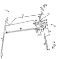
- FIG. 1 In the vehicle roof 1 shown in FIG. 1 is an adjustable hardtop with a front roof part 2 and a rear roof part 3, each of which is rigid in itself and are held by a roof kinematic 4 to the vehicle body and by means of a hydraulic cylinder. 5 trained adjusting element, which is also hinged to the vehicle body, between the closed position shown in Fig. 1 and the storage position shown in Fig. 3 is to be adjusted.
- the roof kinematics 4 comprises a four-bar link, consisting of a body-mounted drive arm 6, a likewise mounted on the body side support arm 7 and a two handlebar articulated connecting C-handlebar 8.
- the rear roof part 3 is coupled to the vehicle body, where appropriate, the C Column link 8 may also be formed by a portion of the roof part 3.
- the hydraulic cylinder 5 On the drive link 6 of the four-bar linkages the hydraulic cylinder 5, which is also pivotally mounted on the body side. If the piston rod of the hydraulic cylinder 5 is extended translationally, the drive link 6 pivots about its body-fixed axis of rotation and thereby actuates the entire roof kinematics, which leads to an actuating movement of the vehicle roof 1.
- the roof kinematics 4 further comprises a body side pivotally mounted auxiliary link 9, to which a main link 10 is pivotally coupled, the rear of the auxiliary link 9 end facing pivotally connected to the front roof part 2. Furthermore, a coupling link 16 is provided, which couples the drive link 6 with the auxiliary link 9 and is rotatably mounted both on the side of the drive link 6 and on the side of the auxiliary link 9. About this coupling a kinematic clearly defined movement of the front roof part 2 is achieved.
- the spring element 11 is designed in the embodiment as a gas spring, which is pivotally mounted on the vehicle body and engages the support arm 7 at a joint 7b.
- the support arm 7 is designed as a wishbone, which is pivotally mounted on the vehicle body via a middle joint 7a and pivotally connected to the C-pillar guide 8 via a further joint 7c, which is opposite to the joint 7b.
- the spring element 11 is arranged and designed in such a way that acts in the closed position of the vehicle roof shown in Fig.
- the torque in the direction of arrow 13 supports the movement of the roof kinematics 4 in an export movement of the hydraulic cylinder 5 in the direction of arrow 14 at the beginning of the adjusting movement, with which the vehicle roof is lifted from the closed position shown and pivoted to the storage position.
- the assisting torque generated by the spring member 11 facilitates the lifting movement out of the closed position.
- the arrow direction 13, which represents the effect of the torque on the support arm 7, is identical to the initial rotational movement of the support arm upon actuation of the hydraulic cylinder 5 for lifting the roof.
- the vehicle roof 1 is shown in an intermediate position between the closed position and the storage position.
- the hydraulic cylinder 5 is not yet fully extended and continues to move in the direction of arrow 14, so that the final storage position can be achieved.
- the support arm 7, however, has reached a reversal position: If this reversal position is exceeded, the direction of rotation of the support arm 7 is reversed from the direction of arrow 13 shown in Fig. 1 counterclockwise to the body-mounted hinge 7a in a movement in the direction of arrow 15 in a clockwise direction, so that when approaching the end position to be reached the support arm is pivoted again in the direction of its starting position.
- the spring element 11 has reached its longest elongated position, which is marked with the excavation l z , said excavation is greater than the marked with l s in Fig. 1 excavation of the spring element 11 in the closed position of vehicle roof.
- the spring element 11 expediently exerts no or a lowest possible spring force on the support arm.
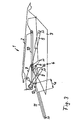
- the vehicle roof 1 is shown in its storage position in a rear-side convertible top compartment.
- the rear roof part 3 is rotated relative to the closed position by approximately 180 °, in particular by about 160 °, and is located with its top down.
- the front roof part 2 has retained its original orientation and lies with the outside up directly on the rear roof part.
- the hydraulic cylinder 5 is maximally extended.
- the support arm 7 has been pivoted so far back relative to the intermediate position shown in FIG. 2, that the excavation l A of the spring element 11 is less than the excavation l Z , which corresponds to the intermediate position of FIG.
- the spring element 11 exerts in the storage position a spring force in the direction of arrow 12 on the support arm 7, whereby it experiences a counterclockwise acting torque acting in the closing direction of the vehicle roof, whereby the lifting operation the storage position is supported out to close the roof by the spring element 11.
- FIGS. 4a and 5a show the vehicle roof in the closed position
- Figs. 4b and 5b represent a transition position between the closing and storage position
- Figs. 4c and 5c show the vehicle roof in the stored position.
- a supported on the vehicle body spring element 11 which engages a side arm 10a of the main link 10 and exerts a spring force F at the point of attack on the side arm 10a.
- the side arm 10a is formed integrally with the main link 10 and encloses an angle with respect to the main link 10.
- the spring element 11 acts on the main link 10 in the closed position of the vehicle roof 1 with a torque acting around the pivot 17 in the direction of the opposite storage position and in the storage position of the vehicle roof in the direction of the opposite closed position.
- the line of action of the spring element 11 intersects the pivot joint of the main link 10, so that the lever arm is zero and no effective torque is transmitted to the main link 10 about the rotational axis of the swivel joint.
- the spring element can also be in an at least approximately relaxed position, so that in this position no spring force is exerted on the side arm 10a and no torque on the main link 10.
- the spring element 11 is designed as a tension spring, which is articulated at one end to the vehicle body and the other end to the side arm 10a and in its tensioned position - as shown in FIGS. 4a and 4c - on the side arm 10a exerts a tensile force according to the arrow F drawn.
- the spring element 11 is designed as a compression spring, which is articulated in an analogous manner to the previous embodiment at one end to the vehicle body and the other end on the side arm 10, but in the end positions of FIG. 5a and 5c on the Side arm 10a exerts a compressive force according to arrows drawn.
- both as a tension spring and as a compression spring - the lifting of the vehicle roof from each end position is supported.
- an embodiment of the spring element 11 comes as a torsion spring into consideration, which generates a torque acting on the pivot 17 on the main link 11.
- the torsion spring is designed in particular in such a way or integrated into the kinematics that in an intermediate position between the end positions no torque is generated or transmitted to the main link.
- the load of the roof kinematics distributed to two different components of the roof kinematics, namely on the acted upon by the passive spring element main link and acted upon by the active drive C-pillar.
- the passively acting spring element supports the rotational movement generated by the active drive, so that small-sized drives can be used. This opens the possibility to use standardized drive units for different roof systems or vehicle roofs and to make individual adjustments on the selection of different strength springs in the passive spring elements.
- Another advantage is the use of active and / or passive rotary actuators, wherein the passive rotary actuators and the translationally linear, acting directly on a leg or side arm of the main link spring elements are to be counted.
- rotary actuators can be dispensed with the use of gearboxes to implement the translatory actuating movement in a rotary rotary motion.
Description
- Die Erfindung bezieht sich auf ein verstellbares Fahrzeugdach nach dem in DE 869159 A offenbarten Oberbegriff des Anspruches 1.
- Aus der Druckschrift DE 199 60 010 C1 ist ein Klappverdeck für Fahrzeuge bekannt, welches zwischen einer den Fahrzeuginnenraum überdeckenden Schließstellung und einer Ablagestellung zu verstellen ist, in der das Verdeck in einem heckseitigen Stauraum abgelegt ist. Das Verdeck ist über eine Dachkinematik, welche an einer karosserieseitigen Konsole gehalten ist, über ein erstes hydraulisches Stellelement zu verstellen. Die Konsole ist schwenkbar an der Fahrzeugkarosserie gelagert und kann über ein zweites hydraulisches Stellelement verschwenkt werden. Diese kombinierte Bewegung über die Dachkinematik einerseits und die die Dachkinematik tragende Konsole andererseits ermöglicht ein kompaktes Ablagemaß, setzt jedoch die Betätigung über zwei separate und energieverbrauchende Stellelemente voraus.
- Aus der Druckschrift DE 198 05 477 C1 ist ein Cabriolet-Fahrzeug mit einem Hardtop-Fahrzeugdach bekannt, das aus zwei in sich starren Dachteilen besteht, die über eine Dachkinematik an die Fahrzeugkarosserie gekoppelt sind und mittels eines an einem Lenker der Dachkinematik angreifenden Steuerelementes zwischen Schließ- und Ablageposition zu verstellen sind. Die Dachkinematik ist als Viergelenkkinematik ausgeführt, über die das hintere Dachteil mit der Fahrzeugkarosserie gekoppelt ist.
- Bei derartigen Kinematiken besteht das Problem, dass auf Grund der vergleichsweise kurzen Hebellängen zwischen karosseriefestem Drehpunkt der Dachkinematik und Angriffspunkt des Steuerelementes verhältnismäßig hohe Stellkräfte für die Überführung des Fahrzeugdaches zwischen den Endpositionen erforderlich sind. Diese hohen Stellkräfte können zwar mit Hilfe hydraulischer Stellelemente erzeugt werden, es besteht jedoch die Gefahr von Bauteilverformungen im Bereich der Kraftangriffspunkte des Stellelementes an der Dachkinematik bzw. an den Abstützpunkten zur Fahrzeugkarosserie.
- Nachteilig ist auch, dass üblicherweise nur in einer der beiden Endlagen des Fahrzeugdaches ein günstiges Hebelverhältnis des Steuerelementes an der Dachkinematik gegeben ist, wohingegen in der jeweils anderen Endlage das Fahrzeugdach aus einer ungünstigen Hebelsituation heraus mit entsprechend hohen Stellkräften angehoben werden muss, wodurch die Gefahr von bauteilschädigenden Stellkräften noch erhöht wird.
- In der Druckschrift DE 100 21 333 C1 wird ein Cabriolet-Fahrzeug mit einem mehrteiligen Hardtop-Fahrzeugdach beschrieben, das mit Hilfe einer Mehrgelenkkinematik zwischen Schließund Ablageposition zu verstellen ist. An der Mehrgelenkkinematik greift eine Spannfeder an, die die Kinematik bei Betätigung eines Bowdenzuges aus einer Totpunktlage löst, um eine Überführung des Daches in die Schließposition zu ermöglichen. Die Spannfeder unterstützt aber nicht den Schließvorgang oder den Ablagevorgang des Daches.
- In der Druckschrift DE 40 26 392 A1 wird ein Aufstelldach für ein Wohnmobil beschrieben, welches gegenüber dem karosseriefesten Dachaufbau des Fahrzeuges bei Bedarf winklig angehoben werden kann. Die Anhebung erfolgt mithilfe einer Aufbaudachkinematik, welche zwei gelenkig gekoppelte Arme umfasst, die zwischen einer zusammengeklappten Position und einer aufgestellten Position zu verstellen sind. Um in etwa das Gewicht des Aufbaudaches in der Aufbaudachkinematik kompensieren zu können, ist an einem Arm der Aufbaudachkinematik eine Zugfeder gehalten, die mit einem um das Gelenk zwischen den Armen gelegten Zugseil verbunden ist, das mit seiner der Zugfeder abgewandten Seite mit dem anderen Arm gekoppelt ist. Die Zugfeder übt permanent eine Öffnungskraft auf die Aufbaudachkinematik aus, welche bestrebt ist, die beiden Lenker aus ihrer zusammengeklappten Schließposition in die Öffnungsposition zu verstellen, in welcher das Aufbaudach aufgestellt ist. Die Federkraft ist in jeder Lage der Aufbaudachkinematik der Gewichtskraft entgegengerichtet, so dass prinzipiell nur dynamische Stellkräfte sowie Reibungskräfte in den Lagern für das Öffnen und Schließen des Aufbaudaches zu überwinden sind. Das Aufbaudach wird somit immer in Richtung seiner geöffneten Position kraftbeaufschlagt.
- Die
BE 493 260 A - Die
DE 32 36 034 A1 offenbart ein Fahrzeugdach mit einer Viergelenk-Dachkinematik. Bei der bekannten Dachkinematik ist der hintere Lenker Bestandteil des hinteren Dachteils und ist einerseits karosserieseitig und andererseits an dem vorderen Dachteil angelenkt. Der Zwischenlenker der bekannten Viergelenk-Dachkinematik wird von dem vorderen Dachteil gebildet, welches zusätzlich an dem vorderen Lenker der Viergelenk-Dachkinematik angelenkt ist. - Die DE-PS 869 159 offenbart ein verstellbares Klappverdeck mit einem kinematischen Verstellmechanismus, der von einem fahrzeugfesten Motor angetrieben wird. Der Verstellmechanismus des Klappverdecks umfasst einen gelenkig an der Fahrzeugkarosserie gelagerten Hauptspriegel, der mit Hilfe eines mehrteiligen Antriebsgelenkmechanismus von dem Antriebsmotor zur Verstellung des Verdeckes zwischen dessen Öffnungs- und Schließposition beaufschlagt wird.
- Des Weiteren ist zwischen dem Hauptspriegel des Verstellmechanismus und der Fahrzeugkarosserie ein Federelement angeordnet, das als Zugfeder ausgebildet ist und sowohl die Schließbewegung als auch die Öffnungsbewegung des Verdeckes jeweils zu Beginn jeder Bewegung unterstützt.
- Der Erfindung liegt das Problem zugrunde, ein verstellbares Fahrzeugdach zu schaffen, welches mit einfachen Mitteln mit verhältnismäßig geringen Stellkräften aus beiden Endlagen anzuheben ist.
- Dieses Problem wird erfindungsgemäß mit den Merkmalen des Anspruches 1 gelöst. Die Unteransprüche enthalten zweckmäßige Weiterbildungen.
- Dem erfindungsgemäßen Fahrzeugdach ist zusätzlich zum Stellelement ein Federelement zugeordnet, welches gegenüber der Fahrzeugkarosserie abgestützt ist und die Dachkinematik in beiden Endpositionen des Fahrzeugdaches - in der Schließposition und der Ablageposition - in Richtung der gegenüberliegenden Endposition kraftbeaufschlagt. Hierdurch wird die Anfangsbewegung des Fahrzeugdaches beim Anheben aus der betreffenden Endposition unterstützt, so dass die von dem Stellelement, welches an der Dachkinematik angreift, aufzubringenden Stellkräfte geringer sein können als im Stand der Technik und die Gefahr von Bauteilverformungen reduziert ist.
- Ein weiterer Vorteil ist darin zu sehen, dass das Federelement auch beim Überführen in die betreffende Endlage wirkt und der Überführungsbewegung zumindest im letzten Bewegungsabschnitt kurz vor Erreichen der Endlage entgegenwirkt, so dass diese Endlage mit einer reduzierten Geschwindigkeitskomponente erreicht wird, die im Idealfall Null ist. Die Endlage wird im Wesentlichen stoß- und impulsfrei erreicht.
- Die Reduzierung der von dem Stellelement aufzubringenden Stellkräfte führt auch zu einer Verkleinerung der Dimensionierung des Stellelementes. Ein weiterer Vorteil besteht darin, dass bei einem Ausfall des Stellelementes das Fahrzeugdach mit geringeren manuellen Kräften zwischen seinen Endpositionen verstellt werden kann.
- Zweckmäßig ist die Dachkinematik in jeder Endposition, also sowohl in der Schließposition als auch in der Ablageposition des Fahrzeugdaches, in die jeweils gegenüberliegende Endposition kraftbeaufschlagt. Es genügt ein einziges Federelement, bei dem es sich beispielsweise um eine Zug-Druck-Feder handeln kann, die in einer Endposition auf Zug und in der gegenüberliegenden Endposition auf Druck beansprucht wird. In einer alternativen Ausführung wird das Federelement in jeder Endposition in der gleichen Wirkrichtung beaufschlagt, was insbesondere dadurch erreicht werden kann, dass das Federelement an einem Bauteil der Dachkinematik angreift, welches zum Anheben des Daches aus jeder der beiden Endpositionen in die gleiche Richtung verstellt wird. Vorteilhaft handelt es sich bei einem derartigen Federelement um eine Gasdruckfeder.
- Die Dachkinematik umfaßt ein Viergelenk mit zwei karosserieseitig abgestützten Lenkern und einem zwischenliegenden Koppellenker oder C-Säulenlenker, wobei ein erster der karosserieseitigen Lenker als Antriebslenker von dem Stellelement beaufschlagt wird und zweckmäßig der zweite karosserieseitige Lenker als Stützlenker von dem Federelement beaufschlagt wird. Der Stützlenker ist insbesondere als Dreieckslenker ausgebildet, der über ein mittleres Gelenk karosseriefest gehalten ist und über zwei außen liegende Gelenke mit dem verbindenden Koppellenker sowie mit dem Federelement verbunden ist. Der Stützlenker führt bevorzugt sowohl bei der Überführung des Daches von Schließ- in Ablageposition als auch in Gegenrichtung jeweils eine ähnliche, gleichsinnige Bewegung aus, nämlich eine Schwenkbewegung zunächst in einer Richtung, die sich bei Erreichen einer Zwischenposition des Fahrzeugdaches in eine Schwenkbewegung in Gegenrichtung umkehrt. Diese Ausführung eignet sich in besonders vorteilhafter Weise für den Einsatz eines lediglich in einer Kraftrichtung wirkenden Federelementes wie zum Beispiel die Gasdruckfeder.
- Das Federelement bzw. die Federelemente sind vorzugsweise in der Weise angeordnet bzw. aufeinander abgestimmt, dass die resultierende Federkraft des Federelementes bzw. der Federelemente auf die Dachkinematik in einer Zwischenposition des Fahrzeugdaches zwischen Schließ- und Ablagestellung näherungsweise zu Null wird. Die für die Verstellung des Fahrzeugdaches erforderlichen Stellkräfte, die über das Stellelement aufzubringen sind, werden hierdurch reduziert.
- Eine weitere Verbesserung eines verstellbaren Fahrzeugdaches in der Weise, dass das Dach mit einfachen Mitteln mit verhältnismäßig geringen Stellkräften aus beiden Endlagen anzuheben ist, wobei sich die Verbesserung insbesondere auch durch eine einfache Konstruktion auszeichnen soll, kann dadurch erreicht werden, dass die Dachkinematik einen ein Dachteil abstützenden Hauptlenker umfasst, der karosserieseitig drehbar gelagert ist, und dass das Federelement den Hauptlenker mit Abstand zu dessen karosserieseitiger Drehachse kraftbeaufschlagt. Der Hauptlenker als ein tragendes Bauteil der Dachkinematik wird in dieser Ausführung direkt und unmittelbar von dem Federelement beaufschlagt; weitere, zwischenliegende Bauteile zwischen Fahrzeugkarosserie und Hauptlenker werden für die Anlenkung durch das Federelement nicht benötigt. Hierdurch kann eine einfache und zugleich wirkungsvolle Unterstützung beim Anheben aus der Fahrzeugdach-Endposition realisiert werden.
- Weitere Vorteile und zweckmäßige Ausführungen sind den weiteren Ansprüchen, der beispielhaften Figurenbeschreibung und den Zeichnungen zu entnehmen. Es zeigen:
- Fig. 1
- ein verstellbares Fahrzeugdach mit einer karosserieseitig angelenkten Dachkinematik, die von einem hydraulischen Stellelement sowie von einem als Gasdruckfeder ausgeführten Federelement beaufschlagt wird, in Schließposition des Daches,
- Fig. 2
- das Fahrzeugdach aus Fig. 1 in einer Zwischenposition zwischen Schließ- und Ablagestellung,
- Fig. 3
- das Fahrzeugdach in Ablagestellung in einem heckseitigen Ablageraum,
- Fig. 4a bis Fig. 4c
- ein verstellbares Fahrzeugdach mit einem karosserieseitig schwenkbar gelagerten Hauptlenker, der in jeder Endposition von einem als Zugfeder ausgebildeten Federelement in die jeweils gegenüberliegende Endposition kraftbeaufschlagt ist, dargestellt in Schließposition, in einer Übergangsposition und in Ablageposition,
- Fig. 5a bis Fig. 5c
- den vorhergehenden Figuren entsprechende Darstellungen, jedoch mit einem als Druckfeder ausgeführten Federelement.
- In den Figuren sind gleiche Bauteile mit gleichen Bezugszeichen versehen.
- Bei dem in Fig. 1 dargestellten Fahrzeugdach 1 handelt es sich um ein verstellbares Hardtop mit einem vorderen Dachteil 2 und einem hinteren Dachteil 3, die jeweils in sich starr ausgebildet sind und über eine Dachkinematik 4 an der Fahrzeugkarosserie gehalten sind und mittels eines als Hydraulikzylinder 5 ausgebildeten Stellelements, das ebenfalls karosseriefest angelenkt ist, zwischen der in Fig. 1 gezeigten Schließstellung und der in Fig. 3 gezeigten Ablagestellung zu verstellen ist. Die Dachkinematik 4 umfasst ein Viergelenk, bestehend aus einem karosserieseitig gelagerten Antriebslenker 6, einem ebenfalls karosserieseitig gelagerten Stützlenker 7 sowie einem beide Lenker gelenkig verbindenden C-Säulenlenker 8. Über dieses Viergelenk ist das hintere Dachteil 3 an die Fahrzeugkarosserie gekoppelt, wobei gegebenenfalls der C-Säulenlenker 8 auch durch einen Abschnitt des Dachteiles 3 gebildet sein kann. An dem Antriebslenker 6 des Viergelenks greift der Hydraulikzylinder 5 an, der karosserieseitig ebenfalls schwenkbar gelagert ist. Wird die Kolbenstange des Hydraulikzylinders 5 translatorisch ausgefahren, verschwenkt der Antriebslenker 6 um seine karosseriefeste Drehachse und betätigt dadurch die gesamte Dachkinematik, was zu einer Stellbewegung des Fahrzeugdaches 1 führt.
- Die Dachkinematik 4 umfasst des Weiteren einen karosserieseitig schwenkbar gelagerten Hilfslenker 9, an dem ein Hauptlenker 10 schwenkbar gekoppelt ist, dessen dem Hilfslenker 9 abgewandtes Ende schwenkbar mit dem vorderen Dachteil 2 verbunden ist. Weiterhin ist ein Koppellenker 16 vorgesehen, der den Antriebslenker 6 mit dem Hilfslenker 9 koppelt und sowohl auf Seiten des Antriebslenker 6 als auch auf Seiten des Hilfslenkers 9 drehbar gelagert ist. Über diese Kopplung wird eine kinematisch eindeutig festgelegte Bewegung des vorderen Dachteiles 2 erzielt.
- Der Stützlenker 7, welcher Teil der Viergelenkkinematik ist, über die das hintere Dachteil 3 an der Fahrzeugkarosserie gehalten ist, wird von einem Federelement 11 kraftbeaufschlagt. Das Federelement 11 ist im Ausführungsbeispiel als Gasdruckfeder ausgeführt, die an der Fahrzeugkarosserie schwenkbar gelagert ist und am Stützlenker 7 an einem Gelenk 7b angreift. Der Stützlenker 7 ist als Dreieckslenker ausgeführt, der über ein mittleres Gelenk 7a an der Fahrzeugkarosserie schwenkbar gelagert ist und über ein weiteres Gelenk 7c, das dem Gelenk 7b gegenüberliegt, schwenkbar mit dem C-Säulenlenker 8 verbunden ist. Das Federelement 11 ist in der Weise angeordnet und ausgelegt, dass in der in Fig. 1 gezeigten Schließposition des Fahrzeugdaches vom Federelement 11 eine Feder-Druckkraft in Pfeilrichtung 12 auf das Gelenk 7b am Stützlenker 7 wirkt, wodurch der Stützlenker 7 ein Drehmoment gemäß Pfeilrichtung 13 im Gegenuhrzeigersinn um sein karosserieseitiges Gelenk 7a erfährt. Das Drehmoment in Pfeilrichtung 13 unterstützt die Bewegung der Dachkinematik 4 bei einer Ausfuhrbewegung des Hydraulikzylinders 5 in Pfeilrichtung 14 zu Beginn der Stellbewegung, mit der das Fahrzeugdach aus der gezeigten Schließposition angehoben und in die Ablageposition verschwenkt wird. Das unterstützende Drehmoment, erzeugt von dem Federelement 11, erleichtert die Anhebebewegung aus der Schließposition heraus. Die Pfeilrichtung 13, die die Wirkung des Drehmomentes auf den Stützlenker 7 darstellt, ist identisch mit der Anfangs-Drehbewegung des Stützlenkers bei einer Betätigung des Hydraulikzylinders 5 zum Anheben des Daches.
- In Fig. 2 ist das Fahrzeugdach 1 in einer Zwischenposition zwischen der Schließstellung und der Ablagestellung gezeigt. In dieser Zwischenposition ist der Hydraulikzylinder 5 noch nicht vollständig ausgefahren und bewegt sich weiterhin in Pfeilrichtung 14, damit die endgültige Ablageposition erreicht werden kann. Der Stützlenker 7 hat dagegen eine Umkehrposition erreicht: Wird diese Umkehrposition überschritten, kehrt sich die Drehrichtung des Stützlenkers 7 aus der in der in Fig. 1 gezeigten Pfeilrichtung 13 im Gegenuhrzeigersinn um das karosseriefeste Gelenk 7a in eine Bewegung in Pfeilrichtung 15 im Uhrzeigersinn um, so dass beim Annähern an die zu ereichende Endposition der Stützlenker wieder in Richtung seiner Ausgangsposition verschwenkt wird. In der Zwischenposition gemäß Fig. 2 hat das Federelement 11 seine am weitesten elongierte Position erreicht, welche mit dem Aushub lz gekennzeichnet ist, wobei dieser Aushub größer ist als der mit ls in Fig. 1 gekennzeichnete Aushub des Federelementes 11 in der Schließposition des Fahrzeugdaches. Im Umkehrpunkt des Stützlenkers 7 übt das Federelement 11 zweckmäßig keine bzw. eine geringst mögliche Federkraft auf den Stützlenker aus.
- In Fig. 3 ist das Fahrzeugdach 1 in seiner Ablageposition in einem heckseitigen Verdeckkasten gezeigt. Das hintere Dachteil 3 ist gegenüber der Schließposition um näherungsweise 180° verdreht, insbesondere um etwa 160°, und liegt mit seiner Oberseite nach unten. Das vordere Dachteil 2 hat seine ursprüngliche Ausrichtung behalten und liegt mit der Außenseite nach oben unmittelbar auf dem hinteren Dachteil. Der Hydraulikzylinder 5 ist maximal ausgefahren. Der Stützlenker 7 ist gegenüber der Zwischenposition gemäß Fig. 2 so weit zurückverschwenkt worden, dass der Aushub lA des Federelementes 11 geringer ist als der Aushub lZ, welcher der Zwischenstellung nach Fig. 2 entspricht, und auch geringer ist als der Aushub ls der Schließposition gemäß Fig. 1. Das Federelement 11 übt in der Ablageposition eine Federkraft in Pfeilrichtung 12 auf den Stützlenker 7 aus, wodurch dieser ein im Gegenuhrzeigersinn wirkendes Drehmoment erfährt, das in Schließrichtung des Fahrzeugdaches wirkt, wodurch der Anhebevorgang aus der Ablageposition heraus zum Schließen des Daches durch das Federelement 11 unterstützt wird.
- Beim Schließen des Daches läuft der gesamte Vorgang in entgegen gesetzter Richtung ab.
- Bei den in den folgenden Figuren 4a bis 4c sowie 5a bis 5c dargestellten Ausführungsbeispielen handelt es sich um ein zweiteiliges Hardtop-Fahrzeugdach 1 mit einem vorderen Dachteil 2 und einem hinteren Dachteil 3. Die Dachkinematik zur Überführung des Fahrzeugdaches zwischen Schließposition und Ablageposition umfasst einen Hauptlenker 10, welcher dachseitig gelenkig mit dem vorderen Dachteil 2 und karosserieseitig gelenkig über ein Drehgelenk 17 mit der Fahrzeugkarosserie gekoppelt ist. Am hinteren Dachteil 3, insbesondere an einer C-Säule des hinteren Dachteiles 3, greift ein nicht näher dargestelltes Stellelement an und beaufschlagt das hintere Dachteil 3 gemäß Pfeilrichtung 18 zur Überführung des Fahrzeugdaches zwischen Schließ- und Ablageposition.
- Die Fig. 4a bzw. 5a zeigen das Fahrzeugdach in Schließposition, die Fig. 4b bzw. 5b stellen eine Übergangsstellung zwischen Schließ- und Ablageposition dar und die Fig. 4c und 5c zeigen das Fahrzeugdach in der abgelegten Position.
- Zur Unterstützung beim Anheben des Fahrzeugdaches aus jeder Endposition - sowohl der Schließposition als auch der Ablageposition - ist ein an der Fahrzeugkarosserie abgestütztes Federelement 11 vorgesehen, welches an einem Seitenarm 10a des Hauptlenkers 10 angreift und am Angriffspunkt am Seitenarm 10a eine Federkraft F ausübt. Der Seitenarm 10a ist einteilig mit dem Hauptlenker 10 ausgebildet und schließt gegenüber dem Hauptlenker 10 einen Winkel ein. Das Federelement 11 beaufschlagt den Hauptlenker 10 in der Schließposition des Fahrzeugdaches 1 mit einem um das Drehgelenk 17 wirkenden Drehmoment in Richtung der gegenüberliegenden Ablageposition und in der Ablageposition des Fahrzeugdaches in Richtung der gegenüberliegenden Schließposition.
- In der mittleren Stellung des Fahrzeugdaches gemäß den Fig. 4b und 5b schneidet die Wirklinie des Federelements 11 das Drehgelenk des Hauptlenkers 10, so dass der Hebelarm Null ist und kein wirksames Drehmoment um die Drehachse des Drehgelenks auf den Hauptlenker 10 übertragen wird. Alternativ oder zusätzlich kann sich das Federelement auch in einer zumindest näherungsweise entspannten Position befinden, so dass in dieser Lage keine Federkraft auf den Seitenarm 10a und kein Drehmoment auf den Hauptlenker 10 ausgeübt wird.
- Im Ausführungsbeispiel gemäß den Fig. 4a bis 4c ist das Federelement 11 als Zugfeder ausgebildet, die einenends an der Fahrzeugkarosserie und anderenends an dem Seitenarm 10a angelenkt ist und in ihrer gespannten Lage - wie in den Fig. 4a und 4c dargestellt - auf den Seitenarm 10a eine Zugkraft gemäß eingezeichnetem Pfeil F ausübt.
- Im Ausführungsbeispiel gemäß den Fig. 5a bis 5c ist das Federelement 11 dagegen als Druckfeder ausgeführt, die zwar in analoger Weise zum vorhergehenden Ausführungsbeispiel einenends an der Fahrzeugkarosserie und anderenends am Seitenarm 10 angelenkt ist, jedoch in den Endpositionen gemäß Fig. 5a und 5c auf den Seitenarm 10a eine Druckkraft gemäß eingezeichneten Pfeilen ausübt.
- In beiden Ausführungen - sowohl als Zugfeder als auch als Druckfeder - wird das Anheben des Fahrzeugdaches aus jeder Endposition unterstützt. Gegebenenfalls kommt auch eine Ausführung des Federelements 11 als Drehfeder in Betracht, die ein um das Drehgelenk 17 wirkendes Drehmoment auf den Hauptlenker 11 erzeugt. Die Drehfeder wird insbesondere in der Weise ausgelegt bzw. in die Kinematik integriert, dass in einer Zwischenposition zwischen den Endlagen kein Drehmoment erzeugt bzw. auf den Hauptlenker übertragen wird.
- In der beschriebenen Ausführung verteilt sich die Belastung der Dachkinematik auf zwei unterschiedliche Bauteile der Dachkinematik, nämlich auf den von dem passiven Federelement beaufschlagten Hauptlenker und auf die von dem aktiven Antrieb beaufschlagte C-Säule. Hierdurch werden die auf jedes Bauteil wirkenden Kräfte reduziert. Das passiv wirkende Federelement unterstützt die vom aktiven Antrieb erzeugte Drehbewegung, so dass klein dimensionierte Antriebe verwendet werden können. Dies eröffnet die Möglichkeit, standardisierte Antriebseinheiten für unterschiedliche Dachsysteme bzw. Fahrzeugdächer zu verwenden und individuelle Anpassungen über die Auswahl unterschiedlich starker Federn in den passiven Federelementen durchzuführen.
- Ein weiterer Vorteil liegt in der Verwendung von aktiven und/oder passiven Drehantrieben, wobei zu den passiven Drehantrieben auch die translatorisch linearen, unmittelbar auf einen Schenkel bzw. Seitenarm des Hauptlenkers wirkenden Federelemente zu zählen sind. Bei Drehantrieben kann auf den Einsatz von Getrieben zur Umsetzung der translatorischen Stellbewegung in eine rotatorische Drehbewegung verzichtet werden.
Claims (6)
- Verstellbares Fahrzeugdach, mit einer Dachkinematik (4), über die das Fahrzeugdach (1) mittels eines karosseriefest gehaltenen Stellelements 5, das an der Dachkinematik (4) angreift, zwischen zwei Endpositionen - eine Schließposition und eine Ablageposition - zu verstellen ist, wobei an der Fahrzeugkarosserie ein Federelement (11) abgestützt ist, das die Dachkinematik (4) in jeder Endposition des Fahrzeugdaches (1) in Richtung der gegenüberliegenden Endposition kraftbeaufschlagt,
dadurch gekennzeichnet,
dass das Fahrzeugdach ein vorderes Dachteil (2) und ein hinteres Dachteil (3) aufweist, und dass die Dachkinematik (4) ein Viergelenk mit zwei karosserieseitig abgestützten Lenkern (6, 7) und einem zwischenliegenden C-Säulenlenker (8) umfasst, wobei einer der karosserieseitigen Lenker als Antriebslenker (6) von dem Stellelement (5) und der zweite karosserieseitige Lenker als Stützlenker (7) von dem Federelement (11) beaufschlagt ist, und dass die Dachkinematik (4) einen karosserieseitig schwenkbar gelagerten Hilfslenker (9) aufweist, an dem ein schwenkbar mit dem vorderen Dachteil (2) gekoppelter Hauptlenker (10) schwenkbar gekoppelt ist, und dass ein Koppellenker (16) vorgesehen ist, der den Antriebslenker (6) mit dem Hilfslenker (9) koppelt und sowohl auf Seiten des Antriebslenkers (6) als auch auf Seiten des Hilfslenkers (9) drehbar gelagert ist. - Fahrzeugdach nach Anspruch 1,
dadurch gekennzeichnet,
dass der Stützlenker (7) als Dreieckslenker ausgebildet ist, der über sein mittleres Gelenk (7a) karosseriefest gehalten ist, wobei über die beiden außenliegenden Gelenke (7b, 7c) des Stützlenkers (7) die Verbindung mit dem C-Säulenlenker (8) bzw. mit dem Federelement (11) geschaffen ist. - Fahrzeugdach nach Anspruch 1 oder 2,
dadurch gekennzeichnet,
dass das an der Dachkinematik (4) angreifende Federelement (11) in beiden Endpositionen des Fahrzeugdaches in gleicher Wirkrichtung federbelastet ist. - Fahrzeugdach nach einem der Ansprüche 1 bis 3,
dadurch gekennzeichnet,
dass die von dem Federelement (11) auf die Dachkinematik (4) übertragene Federkraft in einer Zwischenposition des Daches (1) zwischen den beiden Endpositionen näherungsweise Null ist. - Fahrzeugdach nach einem der Ansprüche 1 bis 4,
dadurch gekennzeichnet,
dass das Federelement (11) eine Gasdruckfeder ist. - Fahrzeugdach nach einem der Ansprüche 1 bis 5,
dadurch gekennzeichnet,
dass das Fahrzeugdach (1) als Hardtop mit mindestens zwei starren Dachteilen (2, 3) ausgeführt ist.
Applications Claiming Priority (5)
| Application Number | Priority Date | Filing Date | Title |
|---|---|---|---|
| DE2001158938 DE10158938A1 (de) | 2001-12-03 | 2001-12-03 | Verstellbares Fahrzeugdach |
| DE10158938 | 2001-12-03 | ||
| DE10206650 | 2002-02-15 | ||
| DE10206650A DE10206650A1 (de) | 2001-12-03 | 2002-02-15 | Verstellbares Fahrzeugdach |
| PCT/EP2002/012370 WO2003047896A1 (de) | 2001-12-03 | 2002-11-06 | Verstellbares fahrzeugdach |
Publications (3)
| Publication Number | Publication Date |
|---|---|
| EP1361966A1 EP1361966A1 (de) | 2003-11-19 |
| EP1361966B1 EP1361966B1 (de) | 2004-09-22 |
| EP1361966B2 true EP1361966B2 (de) | 2007-06-13 |
Family
ID=26010694
Family Applications (1)
| Application Number | Title | Priority Date | Filing Date |
|---|---|---|---|
| EP02804173A Expired - Fee Related EP1361966B2 (de) | 2001-12-03 | 2002-11-06 | Verstellbares fahrzeugdach |
Country Status (4)
| Country | Link |
|---|---|
| US (1) | US6811205B2 (de) |
| EP (1) | EP1361966B2 (de) |
| DE (2) | DE10206650A1 (de) |
| WO (1) | WO2003047896A1 (de) |
Cited By (1)
| Publication number | Priority date | Publication date | Assignee | Title |
|---|---|---|---|---|
| DE102006057509A1 (de) * | 2006-12-06 | 2008-06-12 | Volkswagen Ag | Aufstelldach für ein Fahrzeug, insbesondere für ein Campingfahrzeug |
Families Citing this family (12)
| Publication number | Priority date | Publication date | Assignee | Title |
|---|---|---|---|---|
| DE102004019244B4 (de) * | 2004-04-16 | 2006-06-01 | Cts Fahrzeug-Dachsysteme Gmbh | Lenkerkinematik für ein Fahrzeug-Hardtop |
| DE102004035093B4 (de) * | 2004-07-20 | 2012-06-14 | Webasto-Edscha Cabrio GmbH | Verdeck für ein Cabriolet-Fahrzeug |
| FR2891203B1 (fr) * | 2005-09-29 | 2007-11-16 | Heuliez Sa | Vehicule equipe d'un toit escamotable a actionnement manuel |
| DE102006002030B3 (de) * | 2006-01-13 | 2007-07-12 | Edscha Cabrio-Dachsysteme Gmbh | Heckscheibenansteuerung |
| DE102006020759B3 (de) * | 2006-05-03 | 2007-09-13 | Magna Car Top Systems Gmbh | Bewegliches Dachteil in einem Fahrzeugdach |
| DE102006020758B4 (de) * | 2006-05-03 | 2008-11-27 | Magna Car Top Systems Gmbh | Bewegliches Dachteil in einem Fahrzeugdach |
| DE102006042287A1 (de) * | 2006-09-08 | 2008-03-27 | Dr.Ing.H.C. F. Porsche Ag | Verstellbares Dach |
| DE102006042202A1 (de) * | 2006-09-08 | 2008-03-27 | Dr.Ing.H.C. F. Porsche Ag | Verdeckantrieb |
| DE102007018017B3 (de) | 2007-04-17 | 2008-11-20 | Magna Car Top Systems Gmbh | Umwandelbares Dach für einen Personenkraftwagen |
| DE102008019058A1 (de) * | 2008-04-15 | 2009-10-29 | Magna Car Top Systems Gmbh | Bewegliches Dachteil in einem Fahrzeugdach |
| DE102008026597B4 (de) | 2008-06-03 | 2015-08-27 | Rausch & Pausch Gmbh | Cabrioverdeckvorrichtung |
| DE102009009594B4 (de) * | 2009-02-19 | 2012-10-18 | Webasto-Edscha Cabrio GmbH | Verdeck für ein Cabriolet-Fahrzeug |
Family Cites Families (11)
| Publication number | Priority date | Publication date | Assignee | Title |
|---|---|---|---|---|
| BE493260A (de) * | ||||
| DE869159C (de) * | 1941-06-25 | 1953-04-02 | Auto Union A G | Klappverdeck fuer Kraftfahrzeuge |
| DE3236034C2 (de) * | 1982-09-29 | 1985-11-21 | Ernst Dipl.-Ing. 7801 Schallstadt Maier | Schwenkbares Fahrzeugdach |
| DE3901051A1 (de) * | 1988-03-31 | 1989-10-19 | Daimler Benz Ag | Schwenkunterstuetzung eines den unteren abschluss eines klappverdecks bildenden dachhauthaltebuegels |
| DE4026392C2 (de) | 1990-08-21 | 1999-06-02 | Westfalia Werke Knoebel | Knickstütze für die Aufstelldächer von Fahrzeugen oder dergleichen |
| DE4311260C1 (de) * | 1993-04-06 | 1994-06-01 | Daimler Benz Ag | Federanordnung zur Hilfskraftunterstützung einer schwenkbeweglichen Fahrzeugabdeckung |
| DE4445580C1 (de) * | 1994-12-20 | 1995-12-21 | Daimler Benz Ag | Hardtop-Fahrzeug |
| DE19805477C1 (de) * | 1998-02-11 | 1999-08-05 | Daimler Chrysler Ag | Hardtop-Fahrzeug |
| DE19960010C2 (de) | 1999-12-13 | 2003-07-31 | Cts Fahrzeug Dachsysteme Gmbh | Klappverdeck für Fahrzeuge, insbesondere Personenkraftwagen |
| DE10021333C1 (de) * | 2000-05-02 | 2001-08-09 | Karmann Gmbh W | Cabriolet-Fahrzeug |
| DE10021340C1 (de) * | 2000-05-02 | 2001-08-09 | Karmann Gmbh W | Cabriolet-Fahrzeug |
-
2002
- 2002-02-15 DE DE10206650A patent/DE10206650A1/de not_active Withdrawn
- 2002-11-06 EP EP02804173A patent/EP1361966B2/de not_active Expired - Fee Related
- 2002-11-06 DE DE50201103T patent/DE50201103D1/de not_active Expired - Lifetime
- 2002-11-06 WO PCT/EP2002/012370 patent/WO2003047896A1/de active IP Right Grant
-
2003
- 2003-11-08 US US10/704,493 patent/US6811205B2/en not_active Expired - Fee Related
Cited By (2)
| Publication number | Priority date | Publication date | Assignee | Title |
|---|---|---|---|---|
| DE102006057509A1 (de) * | 2006-12-06 | 2008-06-12 | Volkswagen Ag | Aufstelldach für ein Fahrzeug, insbesondere für ein Campingfahrzeug |
| DE102006057509B4 (de) * | 2006-12-06 | 2019-01-03 | Volkswagen Ag | Aufstelldach für ein Fahrzeug, insbesondere für ein Campingfahrzeug |
Also Published As
| Publication number | Publication date |
|---|---|
| EP1361966A1 (de) | 2003-11-19 |
| DE10206650A1 (de) | 2003-09-04 |
| US20040094987A1 (en) | 2004-05-20 |
| WO2003047896A1 (de) | 2003-06-12 |
| EP1361966B1 (de) | 2004-09-22 |
| US6811205B2 (en) | 2004-11-02 |
| DE50201103D1 (de) | 2004-10-28 |
Similar Documents
| Publication | Publication Date | Title |
|---|---|---|
| DE10108493B4 (de) | Antriebsvorrichtung für ein Klappverdeck und Klappverdeck für ein Cabriolet-Fahrzeug mit einer solchen Antriebsvorrichtung | |
| EP1361966B2 (de) | Verstellbares fahrzeugdach | |
| EP1852291B1 (de) | Bewegliches Dachteil in einem Fahrzeugdach | |
| EP1852290B1 (de) | Bewegliches Dachteil in einem Fahrzeugdach | |
| DE102005005237B3 (de) | Anordnung zum Schwenken der Teile eines Fahrzeugverdecks | |
| EP1658188B1 (de) | Heckdeckel für ein cabriolet-fahrzeug | |
| EP1314601B1 (de) | Verstellbares Fahrzeugdach mit einem Faltverdeck | |
| DE19912893C2 (de) | Cabrio-Fahrzeug mit einem Verdeck | |
| EP1853448B1 (de) | Antriebsvorrichtung eines schwenkbauteils eines fahrzeugs | |
| DE10158938A1 (de) | Verstellbares Fahrzeugdach | |
| EP1673250B1 (de) | Klappverdeck für ein fahrzeug | |
| DE102006057967B4 (de) | Öffnungsfähiges Fahrzeugdach mit einer Viergelenkanordnung | |
| DE10116094C2 (de) | Bewegliches Dachteil in einem Fahrzeugdach | |
| EP1848603B1 (de) | Hardtop-verdeck | |
| DE10117769B4 (de) | Vorrichtung zur Unterstützung einer Öffnungsbewegung einer Fahrzeugklappe | |
| DE10163727A1 (de) | Hardtop-Fahrzeugdach | |
| DE10337353A1 (de) | Cabriolet-Fahrzeug | |
| EP1798090B1 (de) | Hutablage eines Cabriolets | |
| DE102006058320B4 (de) | Cabriolet-Fahrzeug mit angetriebenem Hauptlenkersystem | |
| DE102008036907B4 (de) | Faltverdeck für einen Personenkraftwagen | |
| EP2110278B1 (de) | Bewegliches Dachteil in einem Fahrzeugdach | |
| WO2006079308A1 (de) | Dachsystem mit wenigstens drei dachteilen | |
| DE102009036585B4 (de) | Faltverdeck mit einer Federkrafteinrichtung zur Gewichtsentlastung | |
| DE10149228A1 (de) | Verstellbares Fahrzeugdach | |
| DE10243070A1 (de) | Klappverdeck für Fahrzeuge |
Legal Events
| Date | Code | Title | Description |
|---|---|---|---|
| PUAI | Public reference made under article 153(3) epc to a published international application that has entered the european phase |
Free format text: ORIGINAL CODE: 0009012 |
|
| 17P | Request for examination filed |
Effective date: 20030922 |
|
| AK | Designated contracting states |
Kind code of ref document: A1 Designated state(s): AT BE BG CH CY CZ DE DK EE ES FI FR GB GR IE IT LI LU MC NL PT SE SK TR |
|
| 17Q | First examination report despatched |
Effective date: 20031028 |
|
| GRAP | Despatch of communication of intention to grant a patent |
Free format text: ORIGINAL CODE: EPIDOSNIGR1 |
|
| GRAS | Grant fee paid |
Free format text: ORIGINAL CODE: EPIDOSNIGR3 |
|
| GRAA | (expected) grant |
Free format text: ORIGINAL CODE: 0009210 |
|
| AK | Designated contracting states |
Kind code of ref document: B1 Designated state(s): DE FR GB |
|
| PG25 | Lapsed in a contracting state [announced via postgrant information from national office to epo] |
Ref country code: FR Free format text: LAPSE BECAUSE OF FAILURE TO SUBMIT A TRANSLATION OF THE DESCRIPTION OR TO PAY THE FEE WITHIN THE PRESCRIBED TIME-LIMIT Effective date: 20040922 Ref country code: GB Free format text: LAPSE BECAUSE OF FAILURE TO SUBMIT A TRANSLATION OF THE DESCRIPTION OR TO PAY THE FEE WITHIN THE PRESCRIBED TIME-LIMIT Effective date: 20040922 |
|
| RBV | Designated contracting states (corrected) |
Designated state(s): DE FR GB |
|
| REG | Reference to a national code |
Ref country code: GB Ref legal event code: FG4D Free format text: NOT ENGLISH |
|
| RIN1 | Information on inventor provided before grant (corrected) |
Inventor name: ROESLER, MATTHIAS Inventor name: BRUDER, GERNOT Inventor name: HASSELGRUBER, ANDREAS Inventor name: BERTZ, FRANK Inventor name: PAPENDORF, MARCUS Inventor name: SALZ, WOLFRAM |
|
| REG | Reference to a national code |
Ref country code: IE Ref legal event code: FG4D Free format text: GERMAN |
|
| REF | Corresponds to: |
Ref document number: 50201103 Country of ref document: DE Date of ref document: 20041028 Kind code of ref document: P |
|
| GBV | Gb: ep patent (uk) treated as always having been void in accordance with gb section 77(7)/1977 [no translation filed] |
Effective date: 20040922 |
|
| REG | Reference to a national code |
Ref country code: IE Ref legal event code: FD4D |
|
| PLAQ | Examination of admissibility of opposition: information related to despatch of communication + time limit deleted |
Free format text: ORIGINAL CODE: EPIDOSDOPE2 |
|
| PLBQ | Unpublished change to opponent data |
Free format text: ORIGINAL CODE: EPIDOS OPPO |
|
| PLAQ | Examination of admissibility of opposition: information related to despatch of communication + time limit deleted |
Free format text: ORIGINAL CODE: EPIDOSDOPE2 |
|
| PLAR | Examination of admissibility of opposition: information related to receipt of reply deleted |
Free format text: ORIGINAL CODE: EPIDOSDOPE4 |
|
| PLBI | Opposition filed |
Free format text: ORIGINAL CODE: 0009260 |
|
| PLBQ | Unpublished change to opponent data |
Free format text: ORIGINAL CODE: EPIDOS OPPO |
|
| RAP2 | Party data changed (patent owner data changed or rights of a patent transferred) |
Owner name: CTS FAHRZEUG-DACHSYSTEME GMBH |
|
| PLAX | Notice of opposition and request to file observation + time limit sent |
Free format text: ORIGINAL CODE: EPIDOSNOBS2 |
|
| 26 | Opposition filed |
Opponent name: OPEN AIR SYSTEMS GMBH Effective date: 20050622 |
|
| PLBB | Reply of patent proprietor to notice(s) of opposition received |
Free format text: ORIGINAL CODE: EPIDOSNOBS3 |
|
| EN | Fr: translation not filed | ||
| PLAY | Examination report in opposition despatched + time limit |
Free format text: ORIGINAL CODE: EPIDOSNORE2 |
|
| PLAT | Information related to reply to examination report in opposition deleted |
Free format text: ORIGINAL CODE: EPIDOSDORE3 |
|
| PLBC | Reply to examination report in opposition received |
Free format text: ORIGINAL CODE: EPIDOSNORE3 |
|
| PLBC | Reply to examination report in opposition received |
Free format text: ORIGINAL CODE: EPIDOSNORE3 |
|
| PUAH | Patent maintained in amended form |
Free format text: ORIGINAL CODE: 0009272 |
|
| STAA | Information on the status of an ep patent application or granted ep patent |
Free format text: STATUS: PATENT MAINTAINED AS AMENDED |
|
| 27A | Patent maintained in amended form |
Effective date: 20070613 |
|
| AK | Designated contracting states |
Kind code of ref document: B2 Designated state(s): DE FR GB |
|
| EN | Fr: translation not filed | ||
| PGFP | Annual fee paid to national office [announced via postgrant information from national office to epo] |
Ref country code: DE Payment date: 20131121 Year of fee payment: 12 |
|
| REG | Reference to a national code |
Ref country code: DE Ref legal event code: R119 Ref document number: 50201103 Country of ref document: DE |
|
| PG25 | Lapsed in a contracting state [announced via postgrant information from national office to epo] |
Ref country code: DE Free format text: LAPSE BECAUSE OF NON-PAYMENT OF DUE FEES Effective date: 20150602 |