EP1360924A2 - Applicator device for carrying on the back - Google Patents
Applicator device for carrying on the back Download PDFInfo
- Publication number
- EP1360924A2 EP1360924A2 EP03014976A EP03014976A EP1360924A2 EP 1360924 A2 EP1360924 A2 EP 1360924A2 EP 03014976 A EP03014976 A EP 03014976A EP 03014976 A EP03014976 A EP 03014976A EP 1360924 A2 EP1360924 A2 EP 1360924A2
- Authority
- EP
- European Patent Office
- Prior art keywords
- container
- quick coupling
- mounting plate
- hose
- opening
- Prior art date
- Legal status (The legal status is an assumption and is not a legal conclusion. Google has not performed a legal analysis and makes no representation as to the accuracy of the status listed.)
- Granted
Links
Images


Classifications
-
- A—HUMAN NECESSITIES
- A47—FURNITURE; DOMESTIC ARTICLES OR APPLIANCES; COFFEE MILLS; SPICE MILLS; SUCTION CLEANERS IN GENERAL
- A47L—DOMESTIC WASHING OR CLEANING; SUCTION CLEANERS IN GENERAL
- A47L13/00—Implements for cleaning floors, carpets, furniture, walls, or wall coverings
- A47L13/10—Scrubbing; Scouring; Cleaning; Polishing
- A47L13/28—Polishing implements
- A47L13/30—Implements for polishing and waxing or oiling, with dispensers for wax or oil
-
- A—HUMAN NECESSITIES
- A46—BRUSHWARE
- A46B—BRUSHES
- A46B11/00—Brushes with reservoir or other means for applying substances, e.g. paints, pastes, water
- A46B11/06—Brushes with reservoir or other means for applying substances, e.g. paints, pastes, water connected to supply pipe or to other external supply means
- A46B11/063—Brushes with reservoir or other means for applying substances, e.g. paints, pastes, water connected to supply pipe or to other external supply means by means of a supply pipe
-
- A—HUMAN NECESSITIES
- A46—BRUSHWARE
- A46B—BRUSHES
- A46B17/00—Accessories for brushes
- A46B17/02—Devices for holding brushes in use
-
- A—HUMAN NECESSITIES
- A47—FURNITURE; DOMESTIC ARTICLES OR APPLIANCES; COFFEE MILLS; SPICE MILLS; SUCTION CLEANERS IN GENERAL
- A47L—DOMESTIC WASHING OR CLEANING; SUCTION CLEANERS IN GENERAL
- A47L13/00—Implements for cleaning floors, carpets, furniture, walls, or wall coverings
- A47L13/10—Scrubbing; Scouring; Cleaning; Polishing
- A47L13/20—Mops
- A47L13/22—Mops with liquid-feeding devices
-
- A—HUMAN NECESSITIES
- A46—BRUSHWARE
- A46B—BRUSHES
- A46B2200/00—Brushes characterized by their functions, uses or applications
- A46B2200/30—Brushes for cleaning or polishing
- A46B2200/302—Broom
-
- A—HUMAN NECESSITIES
- A46—BRUSHWARE
- A46B—BRUSHES
- A46B2200/00—Brushes characterized by their functions, uses or applications
- A46B2200/30—Brushes for cleaning or polishing
- A46B2200/3033—Household brush, i.e. brushes for cleaning in the house or dishes
Definitions
- the invention relates to a device for applying a flowable medium on a surface according to the preamble of claim 1.
- a device for applying a flowable medium on a surface is known (US - A - 4 152 084).
- the agent can also be in a container be diluted and poured onto the floor as a diluted application solution become.
- a dispersion application is an example of the previous way of working briefly described.
- Applicators are known in the prior art in which the medium pressurized in a container and passed out of the container.
- the flow rate and the flow rate are influenced and reduced pressure in the container, so that a longer continuous and uniform, effortless work is not possible.
- the corresponding device, from which the invention is based has the advantage that larger ones Amounts of the flowable medium to be applied by the operator can be carried as their arrangement on the back of the operator the work during application is not hindered or impaired and thereby even larger areas continuously and free of charge by one operator can be edited.
- the invention is based on the technical problem, the device described evolve so that their disadvantages avoided and simple and an inexpensive way to continuously process as large as possible Surface enabling device is created.
- the container is refilled or refilled in a simple manner can be removed without the hose adapter being removed from the outlet opening should be. Furthermore, it is advantageously possible upon termination a processing section the rest of the unused medium in the container to leave if the outlet opening after removing the hose adapter is closed by a cover.
- the Container coupling elements on the quick coupling device of the Mounting plate are matched. In another embodiment, they are on the quick coupling device of the mounting plate coordinated coupling elements provided on a container holder. In this container receptacle can use commercial product containers and thus with the help of the container holder be carried on the operator's back. If the container has the coupling elements, it is a universal container suitable in which the corresponding media from the commercially available product containers be filled in.
- hose adapter is a is particularly advantageous locking system matched to the connecting piece of the outlet opening, for example, has a screw or bayonet lock.
- the closure system is designed so that it is commercially available on the closure Container fits so that the same hose adapter both on the outlet opening of the universal container as well as on the outlet opening of the product container can be put on.
- the hose adapter advantageously has a ventilation element so that the container does not have a separate ventilation device for Pressure equalization is required and the container at the end of the machining process after removing the hose adapter directly in a pressure-balanced state can be closed again by the cap.
- the universal container has a filling opening on that in shape and / or size for filling the media without Funnel or similar means is suitable and through a sealing lid is lockable. This makes it possible to use the medium originally refill the filled quantity without changing the container need or the hose adapter or the line to continue to remove the medium for the line outlet.
- the universal container has a fill level marking on the level for a solvent, for example Water, indicating the amount of solvent corresponding to this level is to be dimensioned such that it contains a predetermined amount of concentrate, the one concentration that is prescribed and advantageous for the respective medium or Dilution guaranteed.
- a solvent for example Water
- the amount of solvent corresponding to this level is to be dimensioned such that it contains a predetermined amount of concentrate, the one concentration that is prescribed and advantageous for the respective medium or Dilution guaranteed.
- the metering valve for regulating the flow of the product is expediently between Hose quick coupling and the outlet of the line on or at the Wiper or applicator arranged so that after removing the line or of the hose from the hose adapter that in the line Amount can still be applied in the desired flow rate.
- the hose quick coupling has an overrun protection has, for example, spring-loaded or by a ball or otherwise closes the connection to the container, so that even without actuating the shut-off device no product after removing the hose or line more flows out of the container.
- the proposed device enables a simple and ergonomically favorable Handling for a wide range of applications with high area coverage and low product consumption.
- Product loss is largely avoided because standard product containers can be used and only minimal product residues when changing containers or cleaning the device (Disposal) accrued, since product residues are normally in the sealed container can stay.
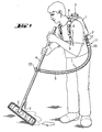
- Fig. 1 an operator is shown, the device according to the invention actuated. It carries in a back carrying device with carrying and Locking straps 8 a mounting plate 9 attached to it, on which a container 1 is coupled. A filling opening is clearly at the upper end of the container 1 3 and at the lower end an outlet opening 2 can be seen, at the connecting piece a hose adapter 11 is connected. From the hose adapter 1 leads a line / hose 6 to a metering valve attached to the handle 4 22, with which the flow of the product / medium can be regulated. The line 6 runs from the metering valve 22 along the stem 4 to one above of the bottom arranged outlet opening 7. On the stem 4 is a wiping or Applicator 5 attached. The product emerges from the outlet opening 7 and is on the floor from a defined height close to the wiping or application device 5 applied and then distributed with the wiper or applicator 5.
- a back carrying device which consists of carrying and locking straps 8 and there attached mounting plate 9, on which a hooking element 20 and a clamping element 21 are attached to the quick coupling device form.
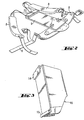
- Fig. 3 is a container receptacle 16 with it attached bracket member 14 and male member 15 shown, the Form coupling elements with which the container receptacle 16 on the mounting plate 9 is coupled.
- FIG. 4 is a back carrying device with carrying and locking straps 8 and attached mounting plate 9 and coupled container receptacle 16 shown.
- the hooking element 20 is in this way in the clamp element 14 inserted that it is fixed in it.
- the insertion element 15 is in the clamping elements 21 inserted so that the receptacle 16 firmly on the Mounting plate 9 is coupled.
- the container receptacle 16 shows in assembled Position at the bottom of a constriction through which a product container / container 1 is held securely, as is clearly shown in FIG. 5.
- a Hose adapter 11 on the connecting piece of the outlet opening 2 of the container 1 is arranged.
- the hose adapter 11 has a shut-off device 12 and underneath a hose quick coupling 13, with which a hose / Line 6 on the container 1 can be connected quickly, easily and safely.
- a ventilation element 17 is arranged, which with a connected outside the container 1 via its topmost pipe 18 is, the upper end open to the atmosphere with a disposable element is secured against leakage.
- Fig. 7 is a universal container 1 in a perspective view obliquely from below shown so that the outlet opening 2 with the threaded connecting piece as well as the filling opening 3 arranged at the opposite end can be seen, which is closed with a sealing lid.
- the coupling elements attached to the universal container 1, namely the clip element 14 and the insertion element 15. are the same Formed as already shown above for the container receptacle 16 and have been described.
- This makes it possible to use both the universal container 1 and alternatively the product container 16 with a handle on the mounting plate 9 to couple and if necessary the universal container against one in one Container receptacle 16 arranged to replace product container / container 1 and vice versa. This means a high degree of flexibility in the application of the Given device.
Abstract
Description
Die Erfindung betrifft eine Vorrichtung zum Auftragen eines fließfähigen Mediums
auf eine Fläche gemäß dem Oberbegriff von Anspruch 1. Eine solche Vorrichtung
ist bekannt (US - A - 4 152 084).The invention relates to a device for applying a flowable medium
on a surface according to the preamble of
Im Stand der Technik wird bei Reinigungs- und Pflegemaßnahmen das Reinigungs-, Desinfektions- oder Pflegemittel aus einem entsprechenden Produktgebinde direkt auf die bevorzugt glatte, ebene oder leicht geneigte Fläche, beispielsweise den Boden, geschüttet. Das Mittel kann aber auch in einem Behälter verdünnt werden und als verdünnte Anwendungslösung auf den Boden geschüttet werden. Beispielhaft für die bisherige Arbeitsweise wird hier ein Dispersionsauftrag kurz beschrieben.In the prior art, cleaning, care and cleaning measures Disinfectant or care product from a corresponding product container directly onto the preferably smooth, flat or slightly inclined surface, for example the ground, poured. The agent can also be in a container be diluted and poured onto the floor as a diluted application solution become. A dispersion application is an example of the previous way of working briefly described.
Zum Aufschütten der Dispersion muß sich die Arbeitskraft in ständigem Wechsel tief beugen, um die Dispersion auf den Boden zu schütten, und den Oberkörper stark nach vorne neigen und gleichzeitig verdrehen, um das Produkt gleichmäßig zu verteilen. Bei dieser Vorgehensweise kann immer nur ein Teilbereich der Fläche bearbeitet werden, bis die aufgeschüttete Menge verarbeitet ist. Häufig wird diese Arbeit auch von zwei Personen durchgeführt, von denen eine die Dispersion auf den jeweils zu bearbeitenden Bereich aufschüttet und die andere die Dispersion gleichmäßig verteilt. In jedem Falle erfolgt ein ständiger, zeitaufwendiger und ermüdender Wechsel zwischen den verschiedenen Arbeitsvorgängen. Ein kontinuierliches Arbeiten, das eine wesentliche Voraussetzung für die gleichbleibende Qualität des Auftrags ist, ist dabei nicht möglich.To fill up the dispersion, the worker has to change constantly bend deeply to pour the dispersion onto the floor and your torso Tilt strongly forward and twist at the same time to make the product even to distribute. With this procedure, only one section can be used of the area can be worked on until the filled amount is processed. Frequently this work is also carried out by two people, one of whom is the Pour the dispersion onto the area to be worked on and the other the dispersion is evenly distributed. In any case, there is a constant, time-consuming and tiring change between the different work processes. A continuous work, which is an essential requirement for the constant quality of the order is not possible.
Bekannt sind im Stand der Technik Auftragvorrichtungen, bei denen das Medium in einem Behälter unter Druck gesetzt und aus dem Behälter geleitet wird. Dabei wird die Durchflußmenge und die Fließgeschwindigkeit beeinflußt und beim Druckabbau im Behälter reduziert, so daß ein längeres kontinuierliches und gleichmäßiges, ansatzfreies Arbeiten nicht möglich ist. Die entsprechende Vorrichtung, von der die Erfindung ausgeht, hat jedoch den Vorteil, daß auch größere Mengen des aufzutragenden fließfähigen Mediums von der Bedienungsperson mitgeführt werden können, da ihre Anordnung auf dem Rücken der Bedienungsperson die Arbeiten beim Auftragen nicht behindert oder beeinträchtigt und dadurch auch größere Flächen kontinuierlich und ansatzfrei von einer Bedienungsperson bearbeitet werden können. Applicators are known in the prior art in which the medium pressurized in a container and passed out of the container. The flow rate and the flow rate are influenced and reduced pressure in the container, so that a longer continuous and uniform, effortless work is not possible. The corresponding device, from which the invention is based, however, has the advantage that larger ones Amounts of the flowable medium to be applied by the operator can be carried as their arrangement on the back of the operator the work during application is not hindered or impaired and thereby even larger areas continuously and free of charge by one operator can be edited.
Der Erfindung liegt das technische Problem zugrunde, die beschriebene Vorrichtung so weiterzuentwickeln, daß deren Nachteile vermieden und auf einfache und kostengünstige Weise eine ein kontinuierliches Bearbeiten möglichst großer Flächen ermöglichende Vorrichtung geschaffen wird.The invention is based on the technical problem, the device described evolve so that their disadvantages avoided and simple and an inexpensive way to continuously process as large as possible Surface enabling device is created.
Dieses Problem wird durch die Merkmale des kennzeichnenden Teils von Anspruch
1 gelöst.This problem is compounded by the features of the characterizing part of
Es ist von Vorteil, daß der Behälter in einfacher Weise nach- oder wiederbefüllt werden kann, ohne daß dazu der Schlauchadapter von der Austrittsöffnung entfernt werden müßte. Ferner ist es in vorteilhafter Weise möglich, bei Beendigung eines Bearbeitungsabschnittes den Rest des nicht verbrauchten Mediums im Behälter zu belassen, wenn die Austrittsöffnung nach Entfernen des Schlauchadapters durch einen Verschlußdeckel verschlossen wird.It is advantageous that the container is refilled or refilled in a simple manner can be removed without the hose adapter being removed from the outlet opening should be. Furthermore, it is advantageously possible upon termination a processing section the rest of the unused medium in the container to leave if the outlet opening after removing the hose adapter is closed by a cover.
Bei der vorgeschlagenen Vorrichtung können zwei verschiedene Behältertypen benutzt werden. Dazu weisen einmal in einer speziellen Ausführungsform die Behälter Kupplungselemente auf, die auf die Schnellkupplungseinrichtung der Montageplatte abgestimmt sind. In einer anderen Ausführungsform sind die auf die Schnellkupplungseinrichtung der Montageplatte abgestimmten Kupplungselemente an einer Gebindeaufnahme vorgesehen. In dieser Gebindeaufnahme können handelsübliche Produktgebinde eingesetzt und somit mit Hilfe der Gebindeaufnahme auf dem Rücken der Bedienungsperson mitgeführt werden. Weist der Behälter die Kupplungselemente auf, so ist dieser als Universalbehälter geeignet, in den die entsprechenden Medien aus den handelsüblichen Produktgebinden eingefüllt werden.In the proposed device, two different types of containers can be used to be used. For this purpose, the Container coupling elements on the quick coupling device of the Mounting plate are matched. In another embodiment, they are on the quick coupling device of the mounting plate coordinated coupling elements provided on a container holder. In this container receptacle can use commercial product containers and thus with the help of the container holder be carried on the operator's back. If the container has the coupling elements, it is a universal container suitable in which the corresponding media from the commercially available product containers be filled in.
Besonders vorteilhaft ist eine Ausführungsform, bei der der Schlauchadapter ein auf den Anschlußstutzen der Austrittsöffnung abgestimmtes Verschlußsystem, beispielsweise einen Schraub- oder Bayonettverschluß aufweist. Zweckmäßig wird das Verschlußsystem so ausgeführt, daß es auf den Verschluß handelsüblicher Gebinde paßt, so daß derselbe Schlauchadapter sowohl auf die Austrittsöffnung des Universalbehälters als auch auf die Austrittsöffnung des Produktgebindes aufgesetzt werden kann. Vorteilhaft weist der Schlauchadapter ein Belüftungselement auf, so daß der Behälter keine separate Belüftungsvorrichtung zum Druckausgleich benötigt und der Behälter beim Ende des Bearbeitungsvorganges nach Entfernung des Schlauchadapters direkt in druckausgeglichenem Zustand wieder durch die Verschlußkappe verschlossen werden kann.An embodiment in which the hose adapter is a is particularly advantageous locking system matched to the connecting piece of the outlet opening, for example, has a screw or bayonet lock. expedient the closure system is designed so that it is commercially available on the closure Container fits so that the same hose adapter both on the outlet opening of the universal container as well as on the outlet opening of the product container can be put on. The hose adapter advantageously has a ventilation element so that the container does not have a separate ventilation device for Pressure equalization is required and the container at the end of the machining process after removing the hose adapter directly in a pressure-balanced state can be closed again by the cap.
In einer vorteilhaften Ausführungsform weist der Universalbehälter eine Einfüllöffnung auf, die in Form und/oder Größe für die Einfüllung der Medien ohne Trichter oder ähnliches Mittel geeignet ist und die durch einen Verschlußdeckel verschließbar ist. Dadurch ist es möglich, das Medium nach Verbrauch der ursprünglich eingefüllten Menge nachzufüllen, ohne den Behälter wechseln zu müssen oder den Schlauchadapter beziehungsweise die Leitung zur Fortführung des Mediums zum Leitungsaustritt zu entfernen. Dadurch, daß Universalbehälter und Gebindeaufnahme beide gleichartige Kupplungselemente aufweisen, die auf die Schnellkupplungseinrichtung der Montageplatte abgestimmt sind, ist es überdies möglich, schnell und einfach den Universalbehälter gegen eine Gebindeaufnahme mit handelsüblichem Produktgebinde auszutauschen und umgekehrt.In an advantageous embodiment, the universal container has a filling opening on that in shape and / or size for filling the media without Funnel or similar means is suitable and through a sealing lid is lockable. This makes it possible to use the medium originally refill the filled quantity without changing the container need or the hose adapter or the line to continue to remove the medium for the line outlet. The fact that universal container and container receptacle both have the same coupling elements that on the quick coupling device of the mounting plate are matched, it is also possible, quick and easy the universal container against a container holder exchange with standard product containers and vice versa.
In einer besonderen Ausführungsform weist der Universalbehälter eine Füllstandsmarkierung auf, die den Füllstand für ein Lösungsmittel, zum Beispiel Wasser, angibt, wobei die diesem Füllstand entsprechende Lösungsmittelmenge so zu bemessen ist, daß sie mit einer vorbestimmten Konzentratmenge, die eine für das jeweilige Medium vorgeschriebene und vorteilhafte Konzentration oder Verdünnung gewährleistet. Dadurch ist es möglich, daß die Bedienungsperson zum Beispiel für wasserlösliche Konzentrate nur die entsprechende Konzentratgrundmenge in einer Dosierpatrone oder einem sonstigen Dosierbehälter mitfuhren muß und dann an jedem im zu bearbeitenden Objekt vorhandenen Wasseranschluß eine neue Behälterfüllung in der gewünschten Konzentration zubereiten kann. Wenn die Nachfüllpatrone oder ein sonstiger Dosierbehälter einen speziellen Verschluß aufweisen, wird eine gesonderte Anschlußeinrichtung für diesen Verschluß zweckmäßigerweise im Verschlußdeckel der Einfüllöffnung vorgesehen.In a special embodiment, the universal container has a fill level marking on the level for a solvent, for example Water, indicating the amount of solvent corresponding to this level is to be dimensioned such that it contains a predetermined amount of concentrate, the one concentration that is prescribed and advantageous for the respective medium or Dilution guaranteed. This makes it possible for the operator For example, for water-soluble concentrates only the corresponding basic amount of concentrate carry it in a dosing cartridge or other dosing container must and then at every water connection in the object to be processed Prepare a new container filling in the desired concentration can. If the refill cartridge or other dosing container has a special Have closure, a separate connection device for this Conveniently provided in the cap of the filler opening.
Damit das Produkt oder Medium beim Ausfließen aus dem Leitungsaustritt nicht bei zu großer Fallhöhe spritzt oder sich bei zu geringem Abstand von der zu bearbeitenden Fläche mit dem Wisch- oder Auftragegerät überschneidet, ist die Austrittsöffnung in einem auf das Produkt oder Medium und dessen Konsistenz abgestimmten Abstand über der Fläche angeordnet.So that the product or medium does not flow out of the pipe outlet if the drop height is too large or if the distance from the one to be processed is too small Area that overlaps with the wiping or application device is the Outlet opening in one on the product or medium and its consistency coordinated distance above the surface.
Das Dosierventil zur Durchflußregulierung des Produkts ist zweckmäßig zwischen Schlauch- Schnellkupplung und dem Austritt der Leitung an oder bei dem Wisch- oder Auftragegerät angeordnet, damit nach Entfernen der Leitung beziehungsweise des Schlauchs vom Schlauchadapter die in der Leitung befindliche Menge noch in der gewünschten Durchflußrate aufgetragen werden kann. Dabei ist es vorteilhaft, wenn die Schlauch- Schnellkupplung einen Nachlaufschutz aufweist, der beispielsweise federbelastet oder durch eine Kugel oder sonstwie die Verbindung zum Behälter verschließt, so daß auch ohne Betätigung der Absperreinrichtung nach Entfernen des Schlauchs oder der Leitung kein Produkt mehr aus dem Behälter nachfließt.The metering valve for regulating the flow of the product is expediently between Hose quick coupling and the outlet of the line on or at the Wiper or applicator arranged so that after removing the line or of the hose from the hose adapter that in the line Amount can still be applied in the desired flow rate. there it is advantageous if the hose quick coupling has an overrun protection has, for example, spring-loaded or by a ball or otherwise closes the connection to the container, so that even without actuating the shut-off device no product after removing the hose or line more flows out of the container.
Die vorgeschlagene Vorrichtung ermöglicht eine einfache und ergonomisch günstige Handhabung für eine breitgefächerte Anwendungspalette bei hoher Flächenleistung und geringem Verbrauch an Produkt. Produktverlust wird weitgehend vermieden, da handelsübliche Produktgebinde eingesetzt werden können und bei Gebindewechsel oder Reinigung der Vorrichtung nur geringe Produktreste (Entsorgung) anfallen, da Produktreste normalerweise im verschlossenen Gebinde bleiben können.The proposed device enables a simple and ergonomically favorable Handling for a wide range of applications with high area coverage and low product consumption. Product loss is largely avoided because standard product containers can be used and only minimal product residues when changing containers or cleaning the device (Disposal) accrued, since product residues are normally in the sealed container can stay.
Die beschriebenen und weitere Vorteile werden anschaulich verdeutlicht bei der Beschreibung von Ausführungsbeispielen, die in beigefügter Zeichnung dargestellt sind. Darin zeigt
- Fig. 1
- eine Bedienungsperson bei der Handhabung einer erfindungsgemäßen Vorrichtung;
- Fig. 2
- eine Rückentragevorrichtung;
- Fig. 3
- eine Gebindeaufnahme mit Kupplungselementen;
- Fig. 4
- eine Rückentrageeinrichtung mit angekuppelter Gebindeaufnahme;
- Fig. 5
- eine Rückentrageeinrichtung mit angekuppelter Gebindeaufnahme und darin eingesetztem Produktgebinde;
- Fig. 6
- einen Schlauchadapter, der an der Austrittsöffhung des Behälters angeschlossen ist, gemäß dem Detail IV in Fig. 5;
- Fig. 7
- einen Universalbehälter mit Kupplungselementen in perspektivischer Darstellung.
- Fig. 1
- an operator when handling a device according to the invention;
- Fig. 2
- a backpack device;
- Fig. 3
- a container holder with coupling elements;
- Fig. 4
- a backpack with coupled container receptacle;
- Fig. 5
- a back support device with coupled container receptacle and product container inserted therein;
- Fig. 6
- a hose adapter, which is connected to the outlet opening of the container, according to detail IV in Fig. 5;
- Fig. 7
- a universal container with coupling elements in a perspective view.
In Fig. 1 ist eine Bedienungsperson dargestellt, die eine erfindungsgemäße Vorrichtung
betätigt. Dabei trägt sie in einer Rückentrageeinrichtung mit Trage- und
Feststellgurten 8 eine daran angebrachte Montageplatte 9, auf der ein Behälter 1
angekuppelt ist. Deutlich ist am oberen Ende des Behälters 1 eine Einfüllöffnung
3 und am unteren Ende eine Austrittsöffnung 2 zu erkennen, an deren Anschlußstutzen
ein Schlauchadapter 11 angeschlossen ist. Vom Schlauchadapter 1 führt
eine Leitung/ Schlauch 6 zu einem am Handhabungsstiel 4 angebrachten Dosierventil
22, mit dem der Durchfluß des Produktes/ Mediums geregelt werden kann.
Vom Dosierventil 22 läuft die Leitung 6 entlang des Stiels 4 bis zu einer oberhalb
des Bodens angeordneten Austrittsöffnung 7. Am Stiel 4 ist ein Wisch- oder
Auftragegerät 5 befestigt. Aus der Austrittsöffnung 7 tritt das Produkt aus und
wird aus definierter Höhe nahe beim Wisch- oder Auftragegerät 5 auf den Boden
aufgetragen und dann mit dem Wisch- oder Auftragegerät 5 verteilt.In Fig. 1 an operator is shown, the device according to the invention
actuated. It carries in a back carrying device with carrying and
Locking straps 8 a mounting plate 9 attached to it, on which a
In Fig. 2 ist eine Rückentrageeinrichtung dargestellt, die aus Trage- und Feststellgurten
8 und daran angebrachter Montageplatte 9 besteht, auf der ein Einhakelement
20 und ein Festklemmelement 21 befestigt sind, die die Schnellkupplungseinrichtung
bilden. In Fig. 3 ist eine Gebindeaufnahme 16 mit daran
angebrachtem Klammerelement 14 und Einsteckelement 15 dargestellt, die die
Kupplungselemente bilden, mit denen die Gebindeaufüahme 16 auf der Montageplatte
9 angekoppelt wird.In Fig. 2 a back carrying device is shown, which consists of carrying and locking
In Fig. 4 ist eine Rückentrageeinrichtung mit Trage- und Feststellgurten 8 und
daran angebrachter Montageplatte 9 und daran angekuppelter Gebindeaufnahme
16 dargestellt. Dabei ist das Einhakelement 20 derart in das Klammerelement 14
eingesteckt, daß es darin festgelegt ist. Das Einsteckelement 15 ist in die Festklemmelemente
21 eingesteckt, so daß die Gebindeaufnahme 16 fest auf der
Montageplatte 9 angekoppelt ist. Die Gebindeaufnahme 16 weist in montierter
Position am unteren Ende eine Einschnürung auf, durch die ein Produktgebinde/Behälter
1 sicher gehalten wird, wie dies in Fig. 5 anschaulich dargestellt ist.In Fig. 4 is a back carrying device with carrying and locking
In Fig. 5 ist die bestückte Rückentrageeinrichtung mit in die Gebindeaufnahme
16 eingesetztem Produktgebinde/ Behälter 1 dargestellt, an dessen Austrittsöffnung
ein Schlauchadapter 11 angeschlossen ist, dargestellt. Der Ausschnitt VI ist
in Fig. 6 vergrößert dargestellt, wobei deutlich zu erkennen ist, daß ein
Schlauchadapter 11 auf dem Anschlußstutzen der Austrittsöffnung 2 des Behälters
1 angeordnet ist. Der Schlauchadapter 11 weist eine Absperreinrichtung 12
und darunter eine Schlauch- Schnellkupplung 13 auf, womit ein Schlauch/ eine
Leitung 6 am Behälter 1 schnell, einfach und sicher angeschlossen werden kann.
Im Schlauchadapter 11 ist ein Belüftungselement 17 angeordnet, das mit einem
außerhalb des Behälters 1 über dessen oberste Stelle geführten Rohr 18 verbunden
ist, dessen oberes zur Atmosphäre offene Ende mit einem Einwegelement
gegen Auslaufen gesichert ist.In Fig. 5 the equipped back carrying device is in the
In Fig. 7 ist ein Universalbehälter 1 in perspektivischer Ansicht von schräg unten
dargestellt, so daß die Austrittsöffnung 2 mit dem Gewinde- Anschlußstutzen
sowie die am gegenüberliegenden Ende angeordnete Einfüllöffnung 3 deutlich
zu erkennen sind, die mit einem Verschlußdeckel verschlossen ist. Gut erkennbar
sind auch die am Universalbehälter 1 befestigten Kupplungselemente, nämlich
das Klammerelement 14 und das Einsteckelement 15. Diese sind in gleicher
Weise ausgebildet, wie sie weiter oben schon für die Gebindeaufnahme 16 dargestellt
und beschrieben wurden. Damit ist es möglich, sowohl den Universalbehälter
1 und alternativ das Produktgebinde 16 mit einem Handgriff an der Montageplatte
9 anzukuppeln und bei Bedarf den Universalbehälter gegen ein in einer
Gebindeaufnahme 16 angeordnetes Produktgebinde/Behälter 1 auszutauschen
und umgekehrt. Damit ist eine hohe Flexibilität in der Anwendung der
Vorrichtung gegeben.In Fig. 7 is a
Claims (10)
einem an einem Stiel (4) angebrachten Wisch- oder Auftragegerät (5),
einer absperrbaren und durchflußregelbaren Leitung (6) für die Fortleitung des Mediums vom Behälter (1) zu einem Austritt an oder bei dem Wisch- oder Auftragegerät (5),
einer Rückentrageeinrichtung mit Trage- und Feststellgurten (8) und einer daran angebrachten Montageplatte (9) für den Behälter (1),
wobei der Behälter (1) am unteren Ende eine wiederverschließbare Austrittsöffnung (2) mit einem Anschlußstutzen aufweist,
dadurch gekennzeichnet, daß die Fortleitung des Mediums vom Behälter (1) schwerkraftbedingt ist.Device for applying a flowable medium to a surface with a ventable container (1) for the medium to be arranged above the surface, with at least one opening (2, 3),
a wiper or applicator (5) attached to a handle (4),
a line (6) which can be shut off and regulated by flow for conveying the medium from the container (1) to an outlet at or at the wiping or application device (5),
a back carrying device with carrying and fixing straps (8) and an attached mounting plate (9) for the container (1),
the container (1) having a reclosable outlet opening (2) with a connecting piece at the lower end,
characterized in that the transfer of the medium from the container (1) is caused by gravity.
Applications Claiming Priority (3)
| Application Number | Priority Date | Filing Date | Title |
|---|---|---|---|
| DE19911131 | 1999-03-12 | ||
| DE19911131A DE19911131C1 (en) | 1999-03-12 | 1999-03-12 | Backpack applicator |
| EP00912541A EP1161173B1 (en) | 1999-03-12 | 2000-03-03 | Rucksack applicator device |
Related Parent Applications (2)
| Application Number | Title | Priority Date | Filing Date |
|---|---|---|---|
| EP00912541.0 Division | 2000-03-03 | ||
| EP00912541A Division EP1161173B1 (en) | 1999-03-12 | 2000-03-03 | Rucksack applicator device |
Publications (3)
| Publication Number | Publication Date |
|---|---|
| EP1360924A2 true EP1360924A2 (en) | 2003-11-12 |
| EP1360924A3 EP1360924A3 (en) | 2004-06-09 |
| EP1360924B1 EP1360924B1 (en) | 2007-08-08 |
Family
ID=7900790
Family Applications (2)
| Application Number | Title | Priority Date | Filing Date |
|---|---|---|---|
| EP03014976A Expired - Lifetime EP1360924B1 (en) | 1999-03-12 | 2000-03-03 | Applicator device for carrying on the back |
| EP00912541A Expired - Lifetime EP1161173B1 (en) | 1999-03-12 | 2000-03-03 | Rucksack applicator device |
Family Applications After (1)
| Application Number | Title | Priority Date | Filing Date |
|---|---|---|---|
| EP00912541A Expired - Lifetime EP1161173B1 (en) | 1999-03-12 | 2000-03-03 | Rucksack applicator device |
Country Status (6)
| Country | Link |
|---|---|
| US (5) | US6550998B1 (en) |
| EP (2) | EP1360924B1 (en) |
| AT (2) | ATE250383T1 (en) |
| DE (3) | DE19911131C1 (en) |
| DK (1) | DK1161173T3 (en) |
| WO (1) | WO2000054647A1 (en) |
Families Citing this family (27)
| Publication number | Priority date | Publication date | Assignee | Title |
|---|---|---|---|---|
| DE19911131C1 (en) * | 1999-03-12 | 2001-01-18 | Henkel Ecolab Gmbh & Co Ohg | Backpack applicator |
| US7232272B2 (en) | 2001-11-14 | 2007-06-19 | Ecolab Inc. | Floor finish application system |
| US7794165B2 (en) | 2001-11-14 | 2010-09-14 | Ecolab Inc. | Floor finish application system including refill station |
| US6695516B2 (en) | 2001-11-14 | 2004-02-24 | Ecolab Inc. | Floor finish application system using applicator pad and matched floor finish composition |
| US20040177868A1 (en) * | 2003-03-11 | 2004-09-16 | Kim Richard J. | Portable spray wash apparatus and method |
| US6854912B2 (en) * | 2003-06-04 | 2005-02-15 | 3M Innovative Properties Company | Mop assembly and cart |
| US20050031404A1 (en) * | 2003-07-16 | 2005-02-10 | Jet Air Industries | Car wash device |
| US20060228160A1 (en) * | 2005-08-01 | 2006-10-12 | Gunsang Lim | Floor Finish Applicator |
| US20080031677A1 (en) * | 2006-08-04 | 2008-02-07 | Curtis Hitchner | An application for dispensing and spreading a liquid on a floor surface |
| US9155380B2 (en) * | 2008-04-28 | 2015-10-13 | Mark Raddick | Fluid dispenser for floors |
| US20110153266A1 (en) * | 2009-12-23 | 2011-06-23 | Regents Of The University Of Minnesota | Augmented vehicle location system |
| US9889464B1 (en) | 2011-12-14 | 2018-02-13 | Clark T. Winne | Apparatus for finishing drywall without sanding |
| WO2013102243A1 (en) * | 2012-01-07 | 2013-07-11 | Technigro Australia Pty Ltd | A liquid applicator device |
| BR112014004057A2 (en) | 2012-07-02 | 2017-03-07 | Sony Corp | transmission device and method, and network device |
| AU2014200877A1 (en) * | 2014-02-20 | 2015-09-03 | Finally Famous Pty Ltd | Bottle of Special Service |
| US9474360B2 (en) * | 2014-03-18 | 2016-10-25 | Umm Al-Qura University | Liquid-dispensing shaving brush |
| US20190001480A1 (en) | 2015-08-17 | 2019-01-03 | Unger Marketing International, Llc | Tool handles having stationary and rotational portions |
| USD872403S1 (en) | 2015-08-17 | 2020-01-07 | Unger Marketing International, Llc | Trigger grip |
| USD864511S1 (en) | 2016-08-16 | 2019-10-22 | Unger Marketing International, Llc | Pole grip |
| USD852444S1 (en) | 2016-08-16 | 2019-06-25 | Unger Marketing International, Llc | Bottle |
| CN107023148B (en) * | 2017-04-13 | 2019-12-10 | 张家港江苏科技大学产业技术研究院 | Multi-painting mode material-sucking and external-permeation type painting tool imitating tool magazine |
| USD881494S1 (en) | 2017-09-11 | 2020-04-14 | Unger Marketing International, Llc | Tool grip |
| USD866899S1 (en) | 2017-09-11 | 2019-11-12 | Unger Marketing International, Llc | Tool grip |
| USD867705S1 (en) | 2017-09-11 | 2019-11-19 | Unger Marketing International, Llc | Bottle |
| US10478038B1 (en) * | 2018-07-13 | 2019-11-19 | Wessol, Llc | Power mop |
| USD911844S1 (en) | 2019-01-18 | 2021-03-02 | Unger Marketing International, Llc | Bottle for a cleaning device |
| US11013393B1 (en) * | 2019-06-24 | 2021-05-25 | Olakunle Harrison | Clog preventive floor finish applicator |
Citations (8)
| Publication number | Priority date | Publication date | Assignee | Title |
|---|---|---|---|---|
| US2083039A (en) * | 1936-01-13 | 1937-06-08 | Edward M Searls | Spraying apparatus |
| US4152084A (en) * | 1977-01-12 | 1979-05-01 | Melton Systems, Inc. | Portable floor finish applicator |
| GB2178303A (en) * | 1985-07-25 | 1987-02-11 | Ronald Arthur Putt | Liquid dispenser for floor cleaning appliances |
| US4848660A (en) * | 1987-03-30 | 1989-07-18 | Thomas Industries, Inc. | Apparatus for carrying a supply of liquid |
| DE3905760A1 (en) * | 1988-08-16 | 1990-02-22 | Henkel Kgaa | DEVICE FOR TREATING TEXTILE FLOORING |
| FR2639818A1 (en) * | 1988-12-06 | 1990-06-08 | Rochex | SOLUTION DISPENSING DEVICE, IN PARTICULAR CLEANING OR DISINFECTING DEVICE, FOR BROOM WITH MACHINE |
| US4971471A (en) * | 1988-09-07 | 1990-11-20 | Sloan David B | Disposable mop |
| DE19707467A1 (en) * | 1996-03-07 | 1997-10-30 | Fichtner Karl Heinz | Mobile drinks bar |
Family Cites Families (28)
| Publication number | Priority date | Publication date | Assignee | Title |
|---|---|---|---|---|
| US2187671A (en) | 1938-03-04 | 1940-01-16 | Lloyd J Suddarth | Applicating device |
| US2768401A (en) | 1953-05-18 | 1956-10-30 | Joseph A Becker | Liquid wax dispenser |
| USRE25556E (en) * | 1958-06-25 | 1964-04-21 | Figure | |
| US2990979A (en) | 1959-01-27 | 1961-07-04 | Signal Mfg Co | Attachment for floor treating apparatus |
| DE1903427A1 (en) * | 1969-01-24 | 1970-08-13 | Rolf Bothe | Apparatus for applying protective varnishes to surfaces |
| US3862466A (en) | 1973-05-04 | 1975-01-28 | Felix S Jabsen | Cleaning apparatus |
| US3981596A (en) | 1974-01-09 | 1976-09-21 | Melton Systems, Inc. | Floor finish applicator |
| DE2834644A1 (en) | 1978-08-08 | 1980-02-28 | Hartmut Dietrich | DEVICE FOR CLEANING PLANNER SURFACES, IN PARTICULAR FLOORS OR THE LIKE. |
| US4588318A (en) | 1980-12-22 | 1986-05-13 | Black & Decker Inc. | Painting applicator with remote transmitter control |
| DE3718141A1 (en) | 1987-05-29 | 1988-12-08 | Henkel Kgaa | DEVICE FOR APPLYING FLOOR CLEANING AND MAINTENANCE PRODUCTS |
| US5050530A (en) | 1989-10-25 | 1991-09-24 | Wilen Manufacturing Co., Inc. | Liquid applicator |
| JPH0753258B2 (en) | 1990-06-15 | 1995-06-07 | 株式会社ホーキイ | Liquid applicator and its moisturizing tray and liquid applicator cloth |
| ITPD910037A0 (en) * | 1991-02-19 | 1991-02-19 | Gianluigi Realdon | WASHING DEVICE |
| DE19600009C1 (en) * | 1996-01-02 | 1997-07-31 | Alfred Buettner | Applicator for paint on road surface |
| US20010055563A1 (en) * | 1999-09-09 | 2001-12-27 | Rhomed Incorporated | Post-labeling stabilization of radiolabeled proteins and peptides |
| ES2202412T3 (en) | 1996-02-13 | 2004-04-01 | Johnsondiversey, Inc. | DEVICE AND PROCEDURE OF SURFACE TREATMENT. |
| GB9720905D0 (en) | 1997-10-03 | 1997-12-03 | Addis Housewares Ltd | Mop Head |
| US6017163A (en) | 1998-02-11 | 2000-01-25 | Ecolab, Inc. | Floor finish distribution apparatus |
| US6413002B1 (en) | 1998-07-20 | 2002-07-02 | Phillip Delaine, Jr. | Aqua broom |
| US6131232A (en) * | 1999-02-19 | 2000-10-17 | Eddy; Colleen | Compact applicator/removal system |
| DE19911131C1 (en) * | 1999-03-12 | 2001-01-18 | Henkel Ecolab Gmbh & Co Ohg | Backpack applicator |
| LU90496B1 (en) | 1999-12-30 | 2003-06-19 | Filmop Srl | Broom fitted with a product flow regulator for cleaning and treating floors |
| US6394683B1 (en) * | 2001-01-30 | 2002-05-28 | Edward Pao | Floor mop with pressurized sprayer |
| US20020186995A1 (en) * | 2001-06-08 | 2002-12-12 | Irina Iosilevich | Multiple pigment application pencil |
| US20020186996A1 (en) | 2001-06-12 | 2002-12-12 | Aramark Corporation | Dispenser |
| US7232272B2 (en) * | 2001-11-14 | 2007-06-19 | Ecolab Inc. | Floor finish application system |
| US6695516B2 (en) * | 2001-11-14 | 2004-02-24 | Ecolab Inc. | Floor finish application system using applicator pad and matched floor finish composition |
| US6854912B2 (en) | 2003-06-04 | 2005-02-15 | 3M Innovative Properties Company | Mop assembly and cart |
-
1999
- 1999-03-12 DE DE19911131A patent/DE19911131C1/en not_active Expired - Fee Related
-
2000
- 2000-03-03 US US09/936,141 patent/US6550998B1/en not_active Expired - Fee Related
- 2000-03-03 DE DE50003832T patent/DE50003832D1/en not_active Expired - Lifetime
- 2000-03-03 WO PCT/EP2000/001832 patent/WO2000054647A1/en active IP Right Grant
- 2000-03-03 EP EP03014976A patent/EP1360924B1/en not_active Expired - Lifetime
- 2000-03-03 AT AT00912541T patent/ATE250383T1/en not_active IP Right Cessation
- 2000-03-03 DK DK00912541T patent/DK1161173T3/en active
- 2000-03-03 DE DE50014552T patent/DE50014552D1/en not_active Expired - Lifetime
- 2000-03-03 EP EP00912541A patent/EP1161173B1/en not_active Expired - Lifetime
- 2000-03-03 AT AT03014976T patent/ATE369067T1/en not_active IP Right Cessation
-
2003
- 2003-04-04 US US10/407,412 patent/US6799916B2/en not_active Expired - Lifetime
-
2004
- 2004-08-04 US US10/911,810 patent/US6951430B2/en not_active Expired - Lifetime
-
2005
- 2005-08-15 US US11/204,805 patent/US7621686B2/en not_active Expired - Lifetime
-
2009
- 2009-06-19 US US12/487,901 patent/US7670073B2/en not_active Expired - Lifetime
Patent Citations (8)
| Publication number | Priority date | Publication date | Assignee | Title |
|---|---|---|---|---|
| US2083039A (en) * | 1936-01-13 | 1937-06-08 | Edward M Searls | Spraying apparatus |
| US4152084A (en) * | 1977-01-12 | 1979-05-01 | Melton Systems, Inc. | Portable floor finish applicator |
| GB2178303A (en) * | 1985-07-25 | 1987-02-11 | Ronald Arthur Putt | Liquid dispenser for floor cleaning appliances |
| US4848660A (en) * | 1987-03-30 | 1989-07-18 | Thomas Industries, Inc. | Apparatus for carrying a supply of liquid |
| DE3905760A1 (en) * | 1988-08-16 | 1990-02-22 | Henkel Kgaa | DEVICE FOR TREATING TEXTILE FLOORING |
| US4971471A (en) * | 1988-09-07 | 1990-11-20 | Sloan David B | Disposable mop |
| FR2639818A1 (en) * | 1988-12-06 | 1990-06-08 | Rochex | SOLUTION DISPENSING DEVICE, IN PARTICULAR CLEANING OR DISINFECTING DEVICE, FOR BROOM WITH MACHINE |
| DE19707467A1 (en) * | 1996-03-07 | 1997-10-30 | Fichtner Karl Heinz | Mobile drinks bar |
Also Published As
| Publication number | Publication date |
|---|---|
| DK1161173T3 (en) | 2003-12-15 |
| US6799916B2 (en) | 2004-10-05 |
| EP1360924B1 (en) | 2007-08-08 |
| ATE250383T1 (en) | 2003-10-15 |
| US20040033101A1 (en) | 2004-02-19 |
| US7621686B2 (en) | 2009-11-24 |
| ATE369067T1 (en) | 2007-08-15 |
| EP1161173A1 (en) | 2001-12-12 |
| US20050019085A1 (en) | 2005-01-27 |
| EP1360924A3 (en) | 2004-06-09 |
| US6550998B1 (en) | 2003-04-22 |
| WO2000054647A1 (en) | 2000-09-21 |
| US7670073B2 (en) | 2010-03-02 |
| DE19911131C1 (en) | 2001-01-18 |
| EP1161173B1 (en) | 2003-09-24 |
| DE50014552D1 (en) | 2007-09-20 |
| US20090257812A1 (en) | 2009-10-15 |
| US20060024119A1 (en) | 2006-02-02 |
| US6951430B2 (en) | 2005-10-04 |
| DE50003832D1 (en) | 2003-10-30 |
Similar Documents
| Publication | Publication Date | Title |
|---|---|---|
| DE19911131C1 (en) | Backpack applicator | |
| DE2731980C2 (en) | Device for dispensing liquid or pasty products | |
| DE60114612T2 (en) | BEVERAGE DISPENSER AND BEVERAGE CONTAINER WITH POSITIONING MEANS | |
| DE3016419A1 (en) | DEVICE FOR APPLYING HARDENING FLOWABLE SUBSTANCES BY SPRAYING ON SURFACES | |
| EP0336415A2 (en) | Spraying device | |
| EP0519292A1 (en) | Siringe-like device for dosing fluids or pastes | |
| DE19618514A1 (en) | Measurement beaker | |
| DE102007012989B4 (en) | Detachable paint coating facility | |
| EP2858864B1 (en) | Storage container, holder for a storage container, and vehicle treatment plant | |
| EP0787099A1 (en) | Device for airing a liquids container | |
| DE3444429A1 (en) | Tapping-off supporting structure | |
| AT401240B (en) | SPRAY SYSTEM WITH SPRAY GUN AND COMPRESSED AIR REGULATOR | |
| DE8611458U1 (en) | Device for the dosed emptying of aerosol cans | |
| DE19536549A1 (en) | Promotion of ideal bulk solids flow esp. of wet plastic granules through vessel | |
| DE8209433U1 (en) | HAND DEVICE | |
| DE7918117U1 (en) | DEVICE FOR FILTERING A LIQUID, IN PARTICULAR HYDRAULIC OIL | |
| DE102017105417B4 (en) | Device for filling tanks with intermediate containers | |
| DE3230596C2 (en) | Device for working with liquids | |
| DE2936428A1 (en) | Hot water supply unit - has top tank opening with hinging funnel for chemical cleaning agent | |
| DE420934C (en) | Container for the transport and wide throwing of seeds | |
| DE1965045B2 (en) | Titration burette elimination in: 1966733 | |
| DE7821387U1 (en) | HOLDER FOR RECEIVING AN AEROSOL CAN | |
| EP1571101A1 (en) | Device for storage and dispense of fluids | |
| DE1747376U (en) | LOCKABLE CASTING DEVICE FOR LIQUID CERAMIC BULK. | |
| DE8522189U1 (en) | Sampling device for a milk quantity measuring device for milking systems |
Legal Events
| Date | Code | Title | Description |
|---|---|---|---|
| PUAI | Public reference made under article 153(3) epc to a published international application that has entered the european phase |
Free format text: ORIGINAL CODE: 0009012 |
|
| AC | Divisional application: reference to earlier application |
Ref document number: 1161173 Country of ref document: EP Kind code of ref document: P |
|
| AK | Designated contracting states |
Kind code of ref document: A2 Designated state(s): AT BE CH CY DE DK ES FI FR GB GR IE IT LI LU MC NL PT SE |
|
| RIN1 | Information on inventor provided before grant (corrected) |
Inventor name: FAUBEL, HEIKO Inventor name: FERNSCHILD, HANS-LEO Inventor name: LENZ, ULRIKE Inventor name: ROGMANN, KARL-HEINZ |
|
| RIN1 | Information on inventor provided before grant (corrected) |
Inventor name: SCHEUVENS, ULRIKE Inventor name: ROGMANN, KARL-HEINZ Inventor name: FERNSCHILD, HANS-LEO Inventor name: FAUBEL, HEIKO |
|
| PUAL | Search report despatched |
Free format text: ORIGINAL CODE: 0009013 |
|
| AK | Designated contracting states |
Kind code of ref document: A3 Designated state(s): AT BE CH CY DE DK ES FI FR GB GR IE IT LI LU MC NL PT SE |
|
| 17P | Request for examination filed |
Effective date: 20041203 |
|
| AKX | Designation fees paid |
Designated state(s): AT BE CH CY DE DK ES FI FR GB GR IE IT LI LU MC NL PT SE |
|
| GRAP | Despatch of communication of intention to grant a patent |
Free format text: ORIGINAL CODE: EPIDOSNIGR1 |
|
| GRAJ | Information related to disapproval of communication of intention to grant by the applicant or resumption of examination proceedings by the epo deleted |
Free format text: ORIGINAL CODE: EPIDOSDIGR1 |
|
| GRAP | Despatch of communication of intention to grant a patent |
Free format text: ORIGINAL CODE: EPIDOSNIGR1 |
|
| GRAS | Grant fee paid |
Free format text: ORIGINAL CODE: EPIDOSNIGR3 |
|
| GRAA | (expected) grant |
Free format text: ORIGINAL CODE: 0009210 |
|
| AC | Divisional application: reference to earlier application |
Ref document number: 1161173 Country of ref document: EP Kind code of ref document: P |
|
| AK | Designated contracting states |
Kind code of ref document: B1 Designated state(s): AT BE CH CY DE DK ES FI FR GB GR IE IT LI LU MC NL PT SE |
|
| REG | Reference to a national code |
Ref country code: GB Ref legal event code: FG4D Free format text: NOT ENGLISH |
|
| REG | Reference to a national code |
Ref country code: CH Ref legal event code: EP |
|
| REG | Reference to a national code |
Ref country code: IE Ref legal event code: FG4D Free format text: LANGUAGE OF EP DOCUMENT: GERMAN |
|
| REF | Corresponds to: |
Ref document number: 50014552 Country of ref document: DE Date of ref document: 20070920 Kind code of ref document: P |
|
| GBT | Gb: translation of ep patent filed (gb section 77(6)(a)/1977) |
Effective date: 20070926 |
|
| ET | Fr: translation filed | ||
| PG25 | Lapsed in a contracting state [announced via postgrant information from national office to epo] |
Ref country code: NL Free format text: LAPSE BECAUSE OF FAILURE TO SUBMIT A TRANSLATION OF THE DESCRIPTION OR TO PAY THE FEE WITHIN THE PRESCRIBED TIME-LIMIT Effective date: 20070808 Ref country code: ES Free format text: LAPSE BECAUSE OF FAILURE TO SUBMIT A TRANSLATION OF THE DESCRIPTION OR TO PAY THE FEE WITHIN THE PRESCRIBED TIME-LIMIT Effective date: 20071119 Ref country code: FI Free format text: LAPSE BECAUSE OF FAILURE TO SUBMIT A TRANSLATION OF THE DESCRIPTION OR TO PAY THE FEE WITHIN THE PRESCRIBED TIME-LIMIT Effective date: 20070808 |
|
| NLV1 | Nl: lapsed or annulled due to failure to fulfill the requirements of art. 29p and 29m of the patents act | ||
| REG | Reference to a national code |
Ref country code: IE Ref legal event code: FD4D |
|
| PG25 | Lapsed in a contracting state [announced via postgrant information from national office to epo] |
Ref country code: DK Free format text: LAPSE BECAUSE OF FAILURE TO SUBMIT A TRANSLATION OF THE DESCRIPTION OR TO PAY THE FEE WITHIN THE PRESCRIBED TIME-LIMIT Effective date: 20070808 Ref country code: GR Free format text: LAPSE BECAUSE OF FAILURE TO SUBMIT A TRANSLATION OF THE DESCRIPTION OR TO PAY THE FEE WITHIN THE PRESCRIBED TIME-LIMIT Effective date: 20071109 |
|
| PG25 | Lapsed in a contracting state [announced via postgrant information from national office to epo] |
Ref country code: PT Free format text: LAPSE BECAUSE OF FAILURE TO SUBMIT A TRANSLATION OF THE DESCRIPTION OR TO PAY THE FEE WITHIN THE PRESCRIBED TIME-LIMIT Effective date: 20080108 Ref country code: IE Free format text: LAPSE BECAUSE OF FAILURE TO SUBMIT A TRANSLATION OF THE DESCRIPTION OR TO PAY THE FEE WITHIN THE PRESCRIBED TIME-LIMIT Effective date: 20070808 |
|
| PLBE | No opposition filed within time limit |
Free format text: ORIGINAL CODE: 0009261 |
|
| STAA | Information on the status of an ep patent application or granted ep patent |
Free format text: STATUS: NO OPPOSITION FILED WITHIN TIME LIMIT |
|
| PG25 | Lapsed in a contracting state [announced via postgrant information from national office to epo] |
Ref country code: SE Free format text: LAPSE BECAUSE OF FAILURE TO SUBMIT A TRANSLATION OF THE DESCRIPTION OR TO PAY THE FEE WITHIN THE PRESCRIBED TIME-LIMIT Effective date: 20071108 |
|
| 26N | No opposition filed |
Effective date: 20080509 |
|
| BERE | Be: lapsed |
Owner name: ECOLAB INC. Effective date: 20080331 |
|
| PG25 | Lapsed in a contracting state [announced via postgrant information from national office to epo] |
Ref country code: MC Free format text: LAPSE BECAUSE OF NON-PAYMENT OF DUE FEES Effective date: 20080331 |
|
| REG | Reference to a national code |
Ref country code: CH Ref legal event code: PL |
|
| PG25 | Lapsed in a contracting state [announced via postgrant information from national office to epo] |
Ref country code: LI Free format text: LAPSE BECAUSE OF NON-PAYMENT OF DUE FEES Effective date: 20080331 Ref country code: CH Free format text: LAPSE BECAUSE OF NON-PAYMENT OF DUE FEES Effective date: 20080331 |
|
| PG25 | Lapsed in a contracting state [announced via postgrant information from national office to epo] |
Ref country code: BE Free format text: LAPSE BECAUSE OF NON-PAYMENT OF DUE FEES Effective date: 20080331 |
|
| PG25 | Lapsed in a contracting state [announced via postgrant information from national office to epo] |
Ref country code: CY Free format text: LAPSE BECAUSE OF FAILURE TO SUBMIT A TRANSLATION OF THE DESCRIPTION OR TO PAY THE FEE WITHIN THE PRESCRIBED TIME-LIMIT Effective date: 20070808 |
|
| PG25 | Lapsed in a contracting state [announced via postgrant information from national office to epo] |
Ref country code: AT Free format text: LAPSE BECAUSE OF NON-PAYMENT OF DUE FEES Effective date: 20080303 |
|
| PG25 | Lapsed in a contracting state [announced via postgrant information from national office to epo] |
Ref country code: LU Free format text: LAPSE BECAUSE OF NON-PAYMENT OF DUE FEES Effective date: 20080303 |
|
| REG | Reference to a national code |
Ref country code: DE Ref legal event code: R082 Ref document number: 50014552 Country of ref document: DE Representative=s name: VON ROHR PATENTANWAELTE PARTNERSCHAFT MBB, DE |
|
| REG | Reference to a national code |
Ref country code: FR Ref legal event code: PLFP Year of fee payment: 17 |
|
| PGFP | Annual fee paid to national office [announced via postgrant information from national office to epo] |
Ref country code: DE Payment date: 20160223 Year of fee payment: 17 |
|
| REG | Reference to a national code |
Ref country code: FR Ref legal event code: PLFP Year of fee payment: 18 |
|
| REG | Reference to a national code |
Ref country code: DE Ref legal event code: R119 Ref document number: 50014552 Country of ref document: DE |
|
| REG | Reference to a national code |
Ref country code: FR Ref legal event code: PLFP Year of fee payment: 19 |
|
| PG25 | Lapsed in a contracting state [announced via postgrant information from national office to epo] |
Ref country code: DE Free format text: LAPSE BECAUSE OF NON-PAYMENT OF DUE FEES Effective date: 20171003 |
|
| PGFP | Annual fee paid to national office [announced via postgrant information from national office to epo] |
Ref country code: FR Payment date: 20190111 Year of fee payment: 20 Ref country code: IT Payment date: 20190326 Year of fee payment: 20 Ref country code: GB Payment date: 20190227 Year of fee payment: 20 |
|
| REG | Reference to a national code |
Ref country code: GB Ref legal event code: PE20 Expiry date: 20200302 |
|
| PG25 | Lapsed in a contracting state [announced via postgrant information from national office to epo] |
Ref country code: GB Free format text: LAPSE BECAUSE OF EXPIRATION OF PROTECTION Effective date: 20200302 |