EP1358901A2 - Aerosol medication inhalation system - Google Patents
Aerosol medication inhalation system Download PDFInfo
- Publication number
- EP1358901A2 EP1358901A2 EP03009988A EP03009988A EP1358901A2 EP 1358901 A2 EP1358901 A2 EP 1358901A2 EP 03009988 A EP03009988 A EP 03009988A EP 03009988 A EP03009988 A EP 03009988A EP 1358901 A2 EP1358901 A2 EP 1358901A2
- Authority
- EP
- European Patent Office
- Prior art keywords
- holding chamber
- delivery
- opening
- mouthpiece
- aerosol
- Prior art date
- Legal status (The legal status is an assumption and is not a legal conclusion. Google has not performed a legal analysis and makes no representation as to the accuracy of the status listed.)
- Granted
Links
Images


Classifications
-
- A—HUMAN NECESSITIES
- A61—MEDICAL OR VETERINARY SCIENCE; HYGIENE
- A61M—DEVICES FOR INTRODUCING MEDIA INTO, OR ONTO, THE BODY; DEVICES FOR TRANSDUCING BODY MEDIA OR FOR TAKING MEDIA FROM THE BODY; DEVICES FOR PRODUCING OR ENDING SLEEP OR STUPOR
- A61M15/00—Inhalators
- A61M15/009—Inhalators using medicine packages with incorporated spraying means, e.g. aerosol cans
-
- A—HUMAN NECESSITIES
- A61—MEDICAL OR VETERINARY SCIENCE; HYGIENE
- A61M—DEVICES FOR INTRODUCING MEDIA INTO, OR ONTO, THE BODY; DEVICES FOR TRANSDUCING BODY MEDIA OR FOR TAKING MEDIA FROM THE BODY; DEVICES FOR PRODUCING OR ENDING SLEEP OR STUPOR
- A61M15/00—Inhalators
- A61M15/0001—Details of inhalators; Constructional features thereof
- A61M15/0013—Details of inhalators; Constructional features thereof with inhalation check valves
- A61M15/0016—Details of inhalators; Constructional features thereof with inhalation check valves located downstream of the dispenser, i.e. traversed by the product
-
- A—HUMAN NECESSITIES
- A61—MEDICAL OR VETERINARY SCIENCE; HYGIENE
- A61M—DEVICES FOR INTRODUCING MEDIA INTO, OR ONTO, THE BODY; DEVICES FOR TRANSDUCING BODY MEDIA OR FOR TAKING MEDIA FROM THE BODY; DEVICES FOR PRODUCING OR ENDING SLEEP OR STUPOR
- A61M15/00—Inhalators
- A61M15/0001—Details of inhalators; Constructional features thereof
- A61M15/0018—Details of inhalators; Constructional features thereof with exhalation check valves
-
- A—HUMAN NECESSITIES
- A61—MEDICAL OR VETERINARY SCIENCE; HYGIENE
- A61M—DEVICES FOR INTRODUCING MEDIA INTO, OR ONTO, THE BODY; DEVICES FOR TRANSDUCING BODY MEDIA OR FOR TAKING MEDIA FROM THE BODY; DEVICES FOR PRODUCING OR ENDING SLEEP OR STUPOR
- A61M15/00—Inhalators
- A61M15/0001—Details of inhalators; Constructional features thereof
- A61M15/0021—Mouthpieces therefor
-
- A—HUMAN NECESSITIES
- A61—MEDICAL OR VETERINARY SCIENCE; HYGIENE
- A61M—DEVICES FOR INTRODUCING MEDIA INTO, OR ONTO, THE BODY; DEVICES FOR TRANSDUCING BODY MEDIA OR FOR TAKING MEDIA FROM THE BODY; DEVICES FOR PRODUCING OR ENDING SLEEP OR STUPOR
- A61M15/00—Inhalators
- A61M15/0086—Inhalation chambers
-
- A—HUMAN NECESSITIES
- A61—MEDICAL OR VETERINARY SCIENCE; HYGIENE
- A61M—DEVICES FOR INTRODUCING MEDIA INTO, OR ONTO, THE BODY; DEVICES FOR TRANSDUCING BODY MEDIA OR FOR TAKING MEDIA FROM THE BODY; DEVICES FOR PRODUCING OR ENDING SLEEP OR STUPOR
- A61M2205/00—General characteristics of the apparatus
- A61M2205/02—General characteristics of the apparatus characterised by a particular materials
- A61M2205/0233—Conductive materials, e.g. antistatic coatings for spark prevention
-
- A—HUMAN NECESSITIES
- A61—MEDICAL OR VETERINARY SCIENCE; HYGIENE
- A61M—DEVICES FOR INTRODUCING MEDIA INTO, OR ONTO, THE BODY; DEVICES FOR TRANSDUCING BODY MEDIA OR FOR TAKING MEDIA FROM THE BODY; DEVICES FOR PRODUCING OR ENDING SLEEP OR STUPOR
- A61M2206/00—Characteristics of a physical parameter; associated device therefor
- A61M2206/10—Flow characteristics
- A61M2206/16—Rotating swirling helical flow, e.g. by tangential inflows
Definitions
- the present invention is directed to apparatus for delivering aerosol medicament to a subject in need of the medicament.
- Delivery systems start with an aerosol-generating device.
- One common example of such devices is a pressurized imetered dose inhaler (MDI).
- MDIs use pressurized gases to disperse medicament as tiny particies or droplets for delivery to the subject.
- a known quantity of gas, and thereby of medicament is ejected from the MDI.
- MDIs have been used with various types of diverse apparatus, in attempts to improve the delivery of this known quantity of medicament to the subject.
- Some problems associated with the delivery of medicament in an aerosol from include, but are not limited to, wastage of medicament in the delivery apparatus, delivery at too high speeds so that medicament sticks to the back of the subject's throat or is inhaled into the subject's sinuses rather than being received into the lungs, ejection of medicament out of the apparatus towards a subject without inhalation thereby, and ejection of medicament from the MDI upon exhalation by the subject into the apparatus prior to inhalation.
- the present invention provides a mouthpiece with a valve for controlling the delivery of aerosolized medicament to a subject.
- the mouthpiece includes a housing that defines a passage through which the medicament flows to the subject.
- the housing has a one-piece valve system that permits passage of medicament aerosol to the subject during inhalation, but does not permit the passage of the subject's breath in the upstream direction during exhalation, with the exhaled breath being expelled through an opening in the sidewall of the housing.
- Another aspect of the present invention combines this mouthpiece and valve system with a holding chamber, which is disposed between the mounthpiece and the source of aerosol.
- the interior of the holding chamber has anti-electrostatic properties to reduce the amount of medicament adhering to the walls of the holding chamber and thereby increase the delivery efficiency of the system.
- a holding chamber is provided with a receptacle member adapted to accept a source of aerosol medicament.
- the receptacle member may aid in the efficient delivery of medicament to the subject, for example by being vented to allow outside air to be mixed with the medicament aerosol in the holding chamber.
- the adhesion of medicament to the walls of the holding chamber can be reduced and the effort necessary to inhale through an apparatus of this type may be reduced.
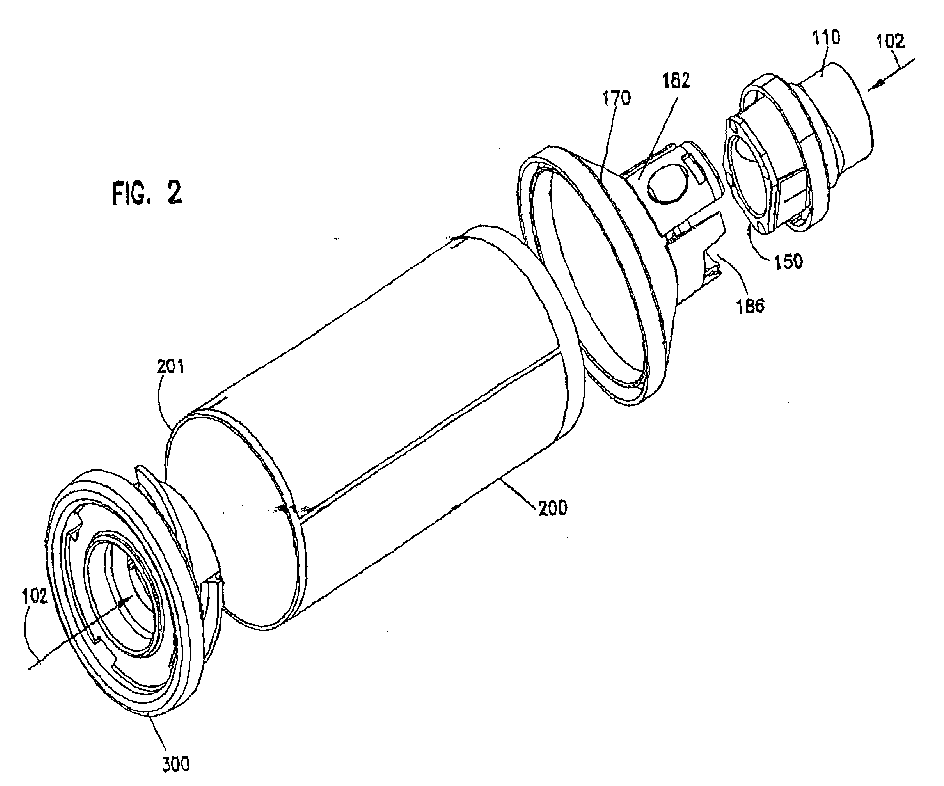
- the aerosol medicament delivery apparatus 10 of the present invention is composed of a holding chamber 200 with first and second ends. At the first end of the holding chamber is a receptacle 300 for connection to a source of aerosol medication.
- aerosol medicament or aerosol medication is intended to include finely divided solid or liquid materials that are carried by a gas for delivery to a subject's respiratory tract, especially to the lungs. This includes nebulized materials.
- the medicament and carrier gas aerosol composition can be prepared prior to use if it exhibits sufficient physical and chemical stability, or it can be prepared in situ from sources of solid or liquid medicament materials (either in pure form or combined with a suitable solid or liquid solvent, excipient or diluent) and pressurized gas.
- the mouthpiece member 100 for delivering aerosol medicament to a subject through a valve 150.
- the mouthpiece member includes a housing 101 that defines a passage 102 through which aerosol medicament can be supplied to a subject and has an opening 103 that opens to the outside of the housing.
- the valve discussed below, is of one-piece construction. During inhalation the valve permits the flow of aerosol medicament from the holding chamber to the subject, while blocking the inflow of outside air to the passage 102 through the sidewall of the housing of the mouthpiece member. During exhalation, the valve blocks the flow of exhaled air upstream in the direction of the holding chamber, and permits the exhaled air to be exhaused through the sidewall of the housing.
- the housing 101 is composed of a delivery member 110 and an adaptor member 170.
- the opening 103 may be defined, as it is in part in the exemplary embodiment, by a notch 186 in the adaptor member.
- the delivery member and adaptor member may be releasably connected by a quick release mechanism 182 .
- the quick release mechanism is a flexible wall, upon which a positioning element 175 may be located.
- the housing is transparent. This has the advantage that it allows for the subject to visually verify the operantion of the valve, to ensure opening and closing during treatment.
- the delivery member 110 may include a subject side section 120 , a connecting ring 130, and an adaptor side section 140.
- the subject side section of the delivery member of the mouthpiece is sized and shaped to fit a human mouth e.g. having an oval shape.
- the subject end section is defined by a housing composed of a sidewall having a height 124, and upon which may be provided at least one ridge 125.
- Positioning pins 141 may be provided on the adaptor side section of the delivery member.
- the adaptor side section 140 of the delivery member 110 in this exemplary embodiment has wall 142 arranged around an opening 145.
- One or more openings for example the illustrated notches 147, is formed in the wall 142 and can define an exhaust opening from the delivery member for exhaled air. This opening is closed by the valve during inhalation, and the opening may be provided with an element to assist in seating a valve member, for example protrusion 146.
- the end face 144 of the wall can be used to as a surface for holding the valve in place when the apparatus is assembled, in cooperation with an opposed surface on the adaptor member.
- the four positioning pins 141 extend from the end face of the wall 142.
- the one-piece two-way valve system 150 allows for inhalation and exhalation with a single valve.
- the valve has a base 151, a first valve element 152, which has a duck-bill shape in this embodiment, and a second valve element 153, which is shaped like a hinged flap 153 in this embodiment.
- the valve is composed of a flexible material and there are two hinged flaps 153.
- the two valve elements may be joined at or carried on a common base 151.
- the base has a thickness 154 that is less than the height of the positioning pins of the mouthpiece, so that the pins may pass therethrough.
- the exemplary embodiment has four positioning holes 156 placed near the perimeter of the base, each being sized to admit the matching positioning plus.
- the duck-bill is a shape predominantly that of a wedge with a very narrow split across the apex of the wedge.
- the split is narrow enough that the two edges forming the ends of the duck-bill are substantially in contact when there is no external pressure on the duck-bill.
- the duck-bill has a span, a height, and a thickness.
- the height of the duck-bill is the vertical distance between the apex of the wedge where the split is located and the base.
- the span is the distance of the split across the thin edge of the wedge and the height.
- the span is sufficiently narrow that the apex of the duck bill will fit within the delivery member without coutacting it.
- the valve may be as wide as possible to provide for easier inhalation, but just narrower than the passage so that the duck-bill sides do not receive pressure and the lips of the duck-bill are not parted except by inhalation.
- Dead space refers to the volume of the apparatus containing air which is rebreathed. Dead space is inherent in any valve-based system enclosed within a mouthpiece or mask; it is the space between the mouth of a subject and the valve. Any subject has a limited volume of air that may be inhaled, and which then is exhaled. This is the subject's tidal volume.
- the inhalation air will contain both oxygen and medicament.
- the exhalation air will contain carbon dioxide.
- all inhalation air will come through the valve and will contain a preferable mixture of medicament laden air. However, this inhalation air will be combined with whatever gases remain scaled within the dead space on their way to being actually inhaled into the subject's respiratory tract. Similarly, when the subject exbales, all air must pass through this dead zone on the way out the exhaust portion of the valve system.
- the dead space will contain gases that then will be re-inhaled during the next breathing cycle.
- the larger the volume of the system's dead space the smaller the volume of medicament laden air the subject will receive with each breathing cycle.
- the larger the volume of dead space the less efficient the system because increasing dead space causes a buildup of carbon dioxide and rehbreathing.
- Rebreathing carbon dioxide can have an adverse effect on breathing rates and patterns, especially for small children who have very small tidal volumes.
- Duck-bill valves are most efficient than diaphragm valves because the volume encompassed by the duck-bill is subtracted from space that otherwise would be dead space in a diaphragm-based system.
- the duck-bill is thin enough that the sides of the wedge will flex when the atmospheric pressure on the opposite side of the base from the duck-bill is greater than that above the duck-bill. This causes the edges of the duck-bill to part, letting air flow through the duck-bill in the direction from the base to mouthpiece.
- air is permined to flow through the mouthpiece to a subject during inhalation.
- the duck-bill closes automatically at the end of inhalation when the atmospheric pressure differential is removed. Thus, the flow of exhaled air upstream of the valve to the holding chamber is prevented during exhalation.
- the exemplary embodiment of the present invention provides two hinged flaps 153 extending from on or near the perimeter of the base.
- Each hinged flap 153 is sized so as to be able to cover a corresponding notch 147 when assembled.
- Each flap is placed on the base at such a position and at such an angle that when the base is placed onto the positioning pins of the mouthpiece, the flap covers one of the notches 147.
- the flap is hinged onto the base so that it may cover the notch 147 during inhalation, thereby preventing the flow of outside air into the interior of the housing through the opening in the sidewall of the housing.
- the notch, of the delivery member 147 and the aforementioned notch of the adaptor member 186 may be aligned radially, and the hinged outgas flap 153 is disposed between these notches.
- the flexible material forming each of the outgas flaps is sufficiently thin to allow an outgas flap to flex through at least a few degrees of flexibility when differences in relative atmospheric pressure caused by human breathing exert flexing pressure on said flap, thereby moving the flap away from the notch 147 during exhalation and allowing exhaled air to pass out of the mouthpiece through the notch 186.
- the subject side section 120 of the delivery member may be formed by a sidewall 128 that is generally cylindrical in shape with an oval cross section.
- the exemplary embodiment has two side points 122 , opposite each other on the sidewall, and two lip points 12 opposite each other on the sidewall. Each lip point is equidistant between the two side points.
- the upper opening of the sidewall 121 at the lip end is oval.
- Ridges 125 may be provided for placement of the subject's lips, or to aid in the placement of an adaptor mask on the outside of the delivery member. Shaped correctly, a ridge 125 may be used to seal and mount such a mask with a tight pressure fit. These ridges are placed approximately halfway down the upper section, and are wedge shaped in the exemplary embodiment. Specifically, they are formed by the upper and lower thickness measurements being equal at the side points and the lower thickness being greater than the upper thickness at the lip points.
- the connecting ring 130 between the adaptor side and subject side sections of the delivery member has an interior opening 135, which may be equal in size to and substantially continuous with the opening of the sidewall of the subject side section. It has an exterior limit 131 that is greater than the interior opening, and a surface 132 where the connecting ring is joined to the subject side section. The surface 132 extends from the sidewall 128 outwards toward the exterior limit 131 where it joins with an exterior wall 133 .
- the exterior wall 133 may be substantially parallel to the sidewall 128 and extends from the top surface in a direction away from the lip end of the subject side section.
- the exterior wall has an interior surface and an exterior surface, the interior surface being closer to the interior opening of the connecting ring.
- there are two contact openings 134 in the top surface which are disposed approximately equidistantly around the circumference of the top surface.
- Each contact hole is adapted to accept a portion of the adaptor member, to help hold the two members of the mouthpiece securely together.
- each has a width less than that of the corresponding contact opening above the catch, a length less than that of the distance between the top and bottom of the exterior wall of the connecting ring, and a height less than the length.
- each section that makes up the wall 142 is approximately as wide as a contact opening in the top surface of the connecting ring.
- Each wall section is disposed along the interior opening substantially adjacent to a contact opening, thus providing a limit to the flexing of the walls of the adaptor member, which is discussed below.
- each wall section has two positioning pins 141 placed along the end face of the wall, extending in the same direction. They are placed near the edge of the wall sections, and can be placed as far apart from each other as the width of a contact opening in the surface of the connecting ring. Due to their height, the sections of the wall 142 extend into the space of the adaptor member when the apparatus is assembled.
- Protrusions 146 may be disposed on the perimeter of the opening forming the passage for exhalation air flow (notches 147 ). These protrusions act as stop elements for the exhaust flap portions of the one-piece valve, limiting their travel in an inward direction. As will be seen in more detail below, when the subject inhales, these exhaust flaps are pressed by suction against the stop elements and form a seal so that the pressure of inhalation is fully directed towards drawing the medicament Iaden air from the holding chamber.
- the adaptor member 170 may be generally frustoconical in shape, thereby providing for the smooth change in diameter from the holding chamber to the delivery member. In the exemplary embodiment, it is both frustoconical and transparent. A transparent embodiment of the present invention has the additional advantage of allowing the subject to visually verify the presence of the medicament during delivery to the patient.
- the adaptor member may have a base end 171, a conical midsection 172, four wall sections, and a delivery side end 173.
- the base end is adapted to cooperate with the edge of the holding chamber, for example forming an exterior wall extending from the end of the cone.
- the base end of the adaptor member also may have an inner wall 174 extending from the end of the cone.
- each of these two walls having a height of at least 0.5 mm to define a groove for accepting the edge of die holding chamber.
- the walls are shaped and positioned such that, when the chamber is positioned between the inner and outer walls and a thin layer of adhesive is applied between the walls, a substantially airtight seal may be formed between the holder and the chamber.
- Other systems for joining the adaptor member and holding chamber may be used, including permanent bonding or releasable connections. The releasable connection may not be needed when the delivery member is made of two readily-separated components that allow for easy cleaning and for replacement of the valve when necessary, as in the illustrated embodiment.
- the wall arising from the frustoconical midsection 172 of the adaptor member 170 may be divided into four sections, including two catch walls 176 and two vent walls 177 in the exemplary embodiment. These may be placed alternately around the delivery side end of the adaptor member.
- Each catch wall 176 may have a catch opening 178 sized to admit one of the catches 136 of the connecting ring 130 of the delivery member 110 and is positioned on the adaptor member such that this opening 178 is adapted to fit a catch 136 when the two adaptor and delivery members are joined.
- the end of the catch wall 176 may fit a contact opening 134 of the connecting ring 130 of the delivery member 110 .
- the catch walls 176 may be flexible, so that they may be bent by the subject applying pressure at the positioning points 175 release the catch 136 from the opening 178 .
- Each valve wall 177 in the exemplary embodiment is U shaped. That is, it is a wall on the long side of the oval opening with a notch 186 in it.
- Other systems for connecting the adaptor member and delivery member can be used.
- the catch and opening could be reversed, i.e. the opening provided on the connecting ring and the catch provided on wall section of the adaptor member.
- the delivery side end of the conical adaptor member may have an opening 185 of substantially the same size as the opening 155 .
- An airtight seal may be formed between the opposing surfaces of the adaptor member and the delivery member by the valve. That is, the valve base 151 may have opposing surfaces arranged to meet those of the adaptor member and the delivery member and form an airtight seal when the apparatus is assembled.
- the exemplary embodiment's adaptor member 170 has a rim 180 around the opening 185 with four positioning openings 181 the rim, one for each pin 141 . Thus, when the two members are joined, the four pins of the delivery member drop into these openings in the exemplary embodiment.
- the cylindrical holding chamber 200 may be defined by a length of cylindrical tube that extends between the mouthpiece 100 and a source of aerosol medicament and includes the receptacle 300 accepting an outlet from a source of aerosol medicament such as a metered dose inhaler or the like.
- the tube wall 201 may be sized to fit between the inner wall 174 and the outer wall 171 of the base of the mouthpiece.
- the holding chamber is made of a lightweight metal or alloy, such as aluminum or an alloy thereof. The use of such material reduces the risk of resistance to medicament flow by static attraction between the particles of medicament and the holding chamber wall.
- the surface of a holding chamber of any material may be treated with an anti-electrostatic coating or process to achieve this advantage.
- the tube is anodized which provides the advantage of sealing the micro-porosity of such a tube's surface and stabilizing it against oxidation.
- the receptacle 300 may include a base with a lip 310, an opening 350 for accepting a source of aerosol medicament in the base with a collar 370 extending into the chamber 200 , an air vent 320 , and a supporting wall 340 that surrounds the opening arising from the base into the chamber.
- the exemplary embodiment has four vents.
- the receptacle base is sized to fit within the tube of the holding chamber. It may be formed of a resilient and flexible material such that it may be removed from the chamber tube (e.g., for cleaning) and replaced many times without loss of functionality, such as maintenance of structural integrity or the ability of the receptacle to form a substantially airtight seal with the tube, throughout the life of the apparatus.
- the receptacle may be removed and replaced hundreds of times without ripping, tearing or otherwise harming the functionality of the apparatus. This removal resilience also applies to the removal and replacement of the source of aerosol medicament from the apparatus.
- the lip 310 of the receptacle fits around the perimeter of the base of the member so that the lip extends beyond the edge of the tube. The lip may be sized such that it forms a substantially airtight seal with the tube. Other systems can be used to join the receptacle to the tube if desired.
- the opening 350 of the receptacle of the exemplary embodiment may be sized to accept several different types of aerosol medicament sources sources such as MDIs.
- the collar 370 is sufficiently long and flexible to form a seal with the aerosol medicament source when one is admitted into the receptacle.
- the supporting wall 340 of the exemplary embodiment is provided with cyclone baffles 330 placed upon the outside of the wall (relative to the opening) and support ribs 360 radially placed upon the inside of the wall.
- the support ribs 360 extend from the wall towards the collar 370 . They are sized so that there is space for the collar to be pressed up against the ribs when a typical MDI is inserted into the opening. Thus, an airtight seal may be formed around the source of the aerosol medicament.
- the support ribs of the exemplary embodiment provide support to the source of aerosol medicament by holding that source against the structure of the collar.
- the vents 320 allow outside air to be drawn into the holding chamber during inhalation. This helps to push the aerosol medicament to the subject during inhalation.
- Each cyclone baffle 330 extends towards the base and is aligned with a vent 320 so that the point where the baffle reaches the base is just beyond the vent. The baffle thus covers the vent.
- the baffle may have a width sufficient to form a seal between the supporting wall and the tube wall of the chamber.
- the exemplary embodiment of the present invention is steam autoclavable either assembled or disassembled. This advantage arises from both the choice of materials used, as herein discussed, and the materials and methods of assembling the components of the invention, such as the quick release mechanism 182 and the use of high-temperature adhesive at the junction of adaptor member 170 and holding chamber 200 . Further, the present invention is easily disassembled for cleaning and parts replacement by a non-technical person.
Abstract
a holding chamber (200) having a first and second ends, the first end being adapted to accept a source of aerosol medicament; and
a mouthpiece member (100) provided at the second end of the holding chamber (200), for delivering aerosol medicament to a subject, the mouthpiece member (200) comprising:
Description
Claims (50)
- An apparatus for aerosol medication delivery, comprising:a holding chamber having a first and second ends, the first and being adapted to accept a source of aerosol medicament; anda mouthpiece member provided at the second and of the holding chamber, for delivering aerosol medicament to a subject, the mouthpiece member comprising:a housing defining a passage through which aexosol medicament can be supplied to a subject and comprising a sidewall in which an opening is formed that opens to the outside of the housing; anda one-piece valve member comprising a first valve element in the passage that permits delivery of aerosol to a subject during inhalation and blocks the possage during exhalation and a second valve element that blocks the opening in the sidewall of the housing during inhalation and is movable away from the opening to permit the flow of air to the outside of the housing from the passage during exhalation.
- The apparatus of claim 1, wherein the housing defining the passage comprises a delivery member and an adaptor member,the adaptor member is provided at the second end of the holding chamber, andthe delivery member is releasably connected to the adaptor member.
- The apparatus of claim 2, wherein the opening in the sidewall of the mouthpiece member is provided in the adaptor member.
- The apparatus of claim 2, wherein the opening in the sidewall of the mouthpiece member is provided in the delivery member.
- The apparatus of claim 2, wherein the opening in the sidewall is defined by a notch defined in an edge of the adaptor member and a notch defined in an edge of the delivery member.
- The apparatus of claim 2, wherein the delivery member is releasably compected to the adaptor member by a quick-release mechanism.
- The apparatus of claim 6, wherein the quick-release mechanism comprises a flexible wall disposed on one of the adaptor member or the delivery member, the flexible wall comprising an engaging member that releasably engages the other of the adaptor member or the deliver member.
- The apparatus of claim 7, wherein the flexible wall comprises a positioning element adapted for a human digit, placed to define a location for flexing the wall to relcase the engaging member.
- The apparatus of claim 1, wherein the mouthpiece is sized and shaped to fit a human mouth.
- The apparatus of claim 1, wherein the delivery member is provided with a ridge.
- The apparatus of claim 10, wherein the ridge is adapted for attaching a mask.
- The apparatus of claim 1, wherein the housing has a stop element that limits the range of motion of the second valve element in the direction of the passage.
- The apparatus of claim 12, wherein the stop element is disposed on the delivery member.
- The apparatus of claim 1, wherein the first valve element is a duck-bill valve.
- The apparatus of claim 1, wherein the valve element is composed of a flexible material.
- The apparatus of claim 1, wherein the second valve element is a hinged flap that seats adjacent the opening in the sidewall.
- The apparatus of claim 2, wherein the first valve element and the second valve element are joined together at a valve base.
- The apparatus of claim 17, wherein the valve base forms a substantially airtight seal between the delivery member and the adaptor member.
- The apparatus of claim 2, wherein the adaptor member and the delivery member define first and second opposed surfaces and the valve member is held between the first and second opposed surfaces.
- The apparatus of claim 19, wherein one of the delivery member and the adaptor member comprises a plurality of pins that extend from one of the first and second opposed surfaces and the other of the delivery member and the adaptor member comprises openings for accepting the pins.
- The apparatus of claim 20, wherein the valve member is provided with openings through which the pins extend.
- The apparatus of claim 5, wherein the notch of the delivery member and the notch of the adaptor member are aligned radially when the mouthpiece is assembled.
- The apparatus of claim 22, wherein the second valve element is disposed between the notches.
- The apparatus of claim 2, wherein one of the delivery member or the adaptor member comprises a pair of radially spaced walls and the other of the delivery member or the adaptor member comprises a wall that extends into the space between the spaced walls.
- The apparatus of claim 1, wherein the mouthpiece member has a first and adapted to the second end of the holding chamber and a second end for delivery of the aerosol medicament. which has an oval shape in lateral cross section.
- The apparatus of claim 1, wherein the housing of the mouthpiece member has inner and outer walls disposed at and in contact with the holding chamber such that the second end of the holding chamber extends into a space between the inner and outer walls.
- The apparatus of claim 1, wherein the mouthpiece member is connected to the holding chamber by an adhesive.
- The apparatus of claim 1, wherein the mouthpiece is formed of a transparent material.
- The apparatus of claim 1, wherein the housing is formed from a transparent material.
- The apparatus of claim 2, wherein the adaptor member is substantially frustoconical in shape.
- The apparatus of claim 2, wherein the adaptor member is formed from a transparent material.
- The apparatus of claim 2, wherein the delivery member is formed from a transparent material.
- The apparatus of claim 1, wherein the holding chamber is cylindrical.
- The apparatus of claim 33, wherein the holding chamber is formed of metal.
- The apparatus of claim 1, wherein the holding chamber is treated with an anti-electrostatic coating.
- The apparatus of claim 1, further comprising a receptacle member at the first end of the holding chamber, having an opening adapted to receive an outlet of an aerosol generating device.
- The apparatus of claim 36, wherein the opening in the receptacle member is capable of accepting outlets of different aerosol generating devices.
- A mouthpiece member for aerosol medicament delivery, having first and second ends, the first end being adapted to accept a source of aerosol medicament and the second end being adapted for delivering aerosol medicament to a subject, the mouthpiece member comprising:a housing defining a passage through which acrosol medicament can be supplied to a subject and comprising a sidewall in which an opening is formed; anda one-piece valve member comprising a first valve element that permits delivery of aerosol a subject during inhalation and blocks the passage during exhalation and a second valve element that blocks the opening in the sidewall of the housing during inhalation and is movable away form the opening to permit the flow of air to the outside of the housing from the passage during exhalation.
- The mouthpiece of claim 38, wherein the housing comprises a substantially frustoconical section.
- An apparatus for aerosol medication delivery, comprising:a mouthpiece member for delivering aerosol medicament to a subject,a holding chamber having first and second ends, the mouthpiece member being disposed at the second end of the chamber anda receptacle member being disposed at the first end of the chamber, the receptacle member comprising:an opening adapted to accept a source of aerosol medicament,a vent permitting fluid communication for the entry of outside air into the holding chamber, anda means for imparting a rotational flow to the outside air entering the holding chamber.
- The apparatus of claim 40, wherein the opening of the receptacle treates an airtight scal around the source of aerosol medicament.
- The of claim 40, wherein the receptacle member is formed of a flexible material such that the receptacle member may be removed from and replaced on the holding chamber without loss of functionality.
- The apparatus of claim 40, wherein the receptacle member has a plurality of vents, disposed equidistantly around the receptacle member.
- The apparatus of claim 40, wherein the receptacle member directs outside air so the wall of the interior of the holding chamber, thus creating a flow of such air along the wall of the holding chamber and reducing particulate deposit from the aerosol medicament within the holding chamber.
- The apparants of claim 40, wherein the means to impart rotational flow comprises at least one baffle disposed on the receptacle member to direct air cutering the holding chamber through a vent into a rotational flow within the chamber.
- The apparatus of claim 42, wherein the receptacle member has a lip around the perimeter of the receptacle member, which encloses the first and of the holding chamber.
- The apparatus of claim 40, wherein the mouthpiece member comprises support ribs for supporting the source of aerosol medicament.
- The apparatus of claim 47, wherein the opening of the receptacle member is defined by a collar that extends inward and may be pushed up against the support ribs for retaining the source of aerosol medicament.
- The apparatus of claim 48, wherein the support ribs are oriented radially when viewed in lateral cross section.
- The apparatus of claim 45, wherein the baffle is a cyclone baffle.
Priority Applications (1)
| Application Number | Priority Date | Filing Date | Title |
|---|---|---|---|
| EP08004544.6A EP2008678B1 (en) | 2002-05-02 | 2003-05-02 | Aerosol medication inhalation system |
Applications Claiming Priority (2)
| Application Number | Priority Date | Filing Date | Title |
|---|---|---|---|
| US137007 | 2002-05-02 | ||
| US10/137,007 US20030205226A1 (en) | 2002-05-02 | 2002-05-02 | Aerosol medication inhalation system |
Related Child Applications (3)
| Application Number | Title | Priority Date | Filing Date |
|---|---|---|---|
| EP08004544.6A Division EP2008678B1 (en) | 2002-05-02 | 2003-05-02 | Aerosol medication inhalation system |
| EP08004544.6A Previously-Filed-Application EP2008678B1 (en) | 2002-05-02 | 2003-05-02 | Aerosol medication inhalation system |
| EP08004544.6A Division-Into EP2008678B1 (en) | 2002-05-02 | 2003-05-02 | Aerosol medication inhalation system |
Publications (3)
| Publication Number | Publication Date |
|---|---|
| EP1358901A2 true EP1358901A2 (en) | 2003-11-05 |
| EP1358901A3 EP1358901A3 (en) | 2003-12-17 |
| EP1358901B1 EP1358901B1 (en) | 2016-10-26 |
Family
ID=29215686
Family Applications (2)
| Application Number | Title | Priority Date | Filing Date |
|---|---|---|---|
| EP03009988.1A Expired - Lifetime EP1358901B1 (en) | 2002-05-02 | 2003-05-02 | Aerosol medication inhalation system |
| EP08004544.6A Expired - Lifetime EP2008678B1 (en) | 2002-05-02 | 2003-05-02 | Aerosol medication inhalation system |
Family Applications After (1)
| Application Number | Title | Priority Date | Filing Date |
|---|---|---|---|
| EP08004544.6A Expired - Lifetime EP2008678B1 (en) | 2002-05-02 | 2003-05-02 | Aerosol medication inhalation system |
Country Status (4)
| Country | Link |
|---|---|
| US (7) | US20030205226A1 (en) |
| EP (2) | EP1358901B1 (en) |
| DE (1) | DE08004544T1 (en) |
| HK (1) | HK1128250A1 (en) |
Cited By (7)
| Publication number | Priority date | Publication date | Assignee | Title |
|---|---|---|---|---|
| USRE43174E1 (en) | 2000-04-11 | 2012-02-14 | Trudell Medical International | Aerosol delivery apparatus |
| WO2012038861A1 (en) * | 2010-09-21 | 2012-03-29 | Koninklijke Philips Electronics N.V. | Valved holding chamber including valve retention system |
| DE102014011271A1 (en) * | 2014-07-29 | 2016-02-04 | Pari GmbH Spezialisten für effektive Inhalation | Ballast chamber with control element for inhaler |
| WO2016024099A1 (en) * | 2014-08-13 | 2016-02-18 | Clement Clarke International Ltd | End fitting for disposable spacer |
| US9700689B2 (en) | 2002-05-21 | 2017-07-11 | Trudell Medical International | Medication delivery apparatus and system and methods for the use and assembly thereof |
| EP3409315A1 (en) * | 2017-06-02 | 2018-12-05 | R. Cegla GmbH & Co. KG | Inhalation system |
| US10556073B2 (en) | 2013-03-26 | 2020-02-11 | R. Cegla Gmbh & Co. Kg | Therapy device for treatment of respiratory diseases |
Families Citing this family (53)
| Publication number | Priority date | Publication date | Assignee | Title |
|---|---|---|---|---|
| US5823179A (en) * | 1996-02-13 | 1998-10-20 | 1263152 Ontario Inc. | Nebulizer apparatus and method |
| EP1370318B1 (en) | 2001-03-15 | 2005-07-20 | The Government of the United States of America, as represented by the Secretary, Department of Health & Human Services | Systems and methods for aerosol delivery of agents |
| CA2809180C (en) | 2001-03-20 | 2015-06-02 | Trudell Medical International | Nebulizer apparatus with an adjustable fluid orifice |
| US20030205226A1 (en) | 2002-05-02 | 2003-11-06 | Pre Holding, Inc. | Aerosol medication inhalation system |
| US7360537B2 (en) * | 2003-04-16 | 2008-04-22 | Trudell Medical International | Antistatic medication delivery apparatus |
| US7748385B2 (en) * | 2003-05-23 | 2010-07-06 | Ric Investments, Inc | Valved holding chamber for use with an aerosol medication delivery system |
| DE10345950A1 (en) * | 2003-10-02 | 2005-05-19 | Pari GmbH Spezialisten für effektive Inhalation | Inhalation therapy device with valve |
| EP1737517B1 (en) * | 2004-04-02 | 2010-10-06 | THE GOVERNMENT OF THE UNITED STATES OF AMERICA, as represented by the Secretary, Department of Health and Human Services | Aerosol delivery systems |
| DK1962805T3 (en) | 2005-12-08 | 2016-09-26 | Insmed Inc | Lipid-based compositions of the anti-infective agents for the treatment of lung infections |
| EP2010260A1 (en) | 2006-04-10 | 2009-01-07 | AEIOMed, Inc. | Apparatus and methods for providing humidity in respiratory therapy |
| US7793658B2 (en) * | 2006-08-21 | 2010-09-14 | Go2 Llc | Personal assistive breathing apparatus |
| US9119783B2 (en) | 2007-05-07 | 2015-09-01 | Insmed Incorporated | Method of treating pulmonary disorders with liposomal amikacin formulations |
| US20100095958A1 (en) * | 2007-08-21 | 2010-04-22 | King Russell W | Pre-filled, single-use, disposable small volume medication nebulizer |
| US20100242955A1 (en) * | 2009-03-19 | 2010-09-30 | Hansen Leland G | Aerosolized Drug Delivery System |
| US10857311B2 (en) | 2010-01-12 | 2020-12-08 | Omega Life Science Ltd. | Method and apparatus for producing fine concentrated aerosol |
| US9757528B2 (en) | 2010-08-23 | 2017-09-12 | Darren Rubin | Nebulizer having different negative pressure threshold settings |
| EP2608829A4 (en) | 2010-08-23 | 2015-11-18 | Darren Rubin | Systems and methods of aerosol delivery with airflow regulation |
| US20120318261A1 (en) * | 2011-06-17 | 2012-12-20 | Nostrum Technology Llc | Valved Holding Chamber With Whistle for the Administration of Inhalable Drugs |
| US9364622B2 (en) | 2012-04-20 | 2016-06-14 | Fsc Laboratories, Inc. | Inhalation devices and systems and methods including the same |
| LT2852391T (en) | 2012-05-21 | 2022-03-10 | Insmed Incorporated | Systems for treating pulmonary infections |
| US9713687B2 (en) * | 2012-08-21 | 2017-07-25 | Philip Morris Usa Inc. | Ventilator aerosol delivery system with transition adapter for introducing carrier gas |
| AU2013352259B2 (en) | 2012-11-29 | 2018-06-14 | Insmed Incorporated | Stabilized vancomycin formulations |
| CA156938S (en) | 2013-02-14 | 2014-07-08 | Clement Clarke Int Ltd | Spacer for an asthma inhaler |
| USD735316S1 (en) | 2013-03-11 | 2015-07-28 | Fsc Laboratories, Inc. | Inhalation spacer |
| US10207065B2 (en) * | 2013-07-12 | 2019-02-19 | John H. Silva | Mouthpiece for inhalers |
| USD747548S1 (en) * | 2013-12-10 | 2016-01-12 | Michael James Mayor | Electronic cigarette tank |
| USD760952S1 (en) * | 2013-12-10 | 2016-07-05 | Michael James Mayor | Electronic cigarette tank with fill port and plug |
| US20150165146A1 (en) | 2013-12-17 | 2015-06-18 | Bruce Bowman | Humidification system and positive airway pressure apparatus incorporating same |
| ES2926985T3 (en) | 2014-05-15 | 2022-10-31 | Insmed Inc | Methods for treating nontuberculous mycobacterial lung infections |
| USD748242S1 (en) | 2014-07-11 | 2016-01-26 | H. Stuart Campbell | Inhaler mouthpiece |
| WO2016059630A1 (en) | 2014-10-13 | 2016-04-21 | Omega Life Science Ltd. | Nebulizers and uses thereof |
| US11116918B2 (en) | 2015-03-02 | 2021-09-14 | Abithas, Inc. | Delivery system for metered dose inhalers |
| US20160256641A1 (en) * | 2015-03-02 | 2016-09-08 | Edward Lisberg | Delivery System for Metered Dose Inhalers |
| US9566399B1 (en) | 2015-04-14 | 2017-02-14 | Clempharma LLC | Deep lung alveolar aerosol targeted drug delivery |
| US9854838B1 (en) * | 2015-09-10 | 2018-01-02 | Rodney Laible | Modular mouthpiece assembly for an electronic cigarette |
| EP3213789B2 (en) | 2016-03-02 | 2022-01-12 | PARI GmbH Spezialisten für effektive Inhalation | Valve |
| US10850050B2 (en) | 2016-05-19 | 2020-12-01 | Trudell Medical International | Smart valved holding chamber |
| USD851746S1 (en) * | 2016-06-08 | 2019-06-18 | Pari GmbH Spezialisten für effektive Inhalation | Spacer chamber for an inhaler |
| USD820433S1 (en) * | 2016-06-08 | 2018-06-12 | Pari GmbH Spezialisten für effektive Inhalation | Spacer chamber with actuator for an inhaler |
| WO2018007997A1 (en) | 2016-07-08 | 2018-01-11 | Trudell Medical International | Smart oscillating positive expiratory pressure device |
| US10786638B2 (en) | 2016-07-08 | 2020-09-29 | Trudell Medical International | Nebulizer apparatus and method |
| ES2920151T3 (en) | 2016-12-09 | 2022-08-01 | Trudell Medical Int | smart nebulizer |
| USD835260S1 (en) * | 2017-04-06 | 2018-12-04 | Abithas, Llc | Delivery assist device for metered dose inhaler |
| MX2020007026A (en) | 2018-01-04 | 2020-12-03 | Trudell Medical Int | Smart oscillating positive expiratory pressure device. |
| CN108114351A (en) * | 2018-01-16 | 2018-06-05 | 浙江百安医疗科技有限公司 | A kind of medical mouth nasal aerosol delivery device |
| CN108295343A (en) * | 2018-01-16 | 2018-07-20 | 浙江百安医疗科技有限公司 | A kind of medical mouth nasal aerosol drug delivery device |
| EP3773505A4 (en) | 2018-03-30 | 2021-12-22 | Insmed Incorporated | Methods for continuous manufacture of liposomal drug products |
| US20190351443A1 (en) * | 2018-05-17 | 2019-11-21 | Indose Inc. | Vaporizer with clog-free channel |
| WO2019236662A1 (en) | 2018-06-05 | 2019-12-12 | Teleflex Medical Incorporated | Valved spacer for inhalation device |
| EP4021542A4 (en) | 2019-08-27 | 2023-09-06 | Trudell Medical International | Smart oscillating positive expiratory pressure device |
| GB2586301B (en) * | 2020-04-07 | 2021-08-25 | Splash Tm Gmbh | Stable-Foam inhalation Device and Cartridge |
| USD1010101S1 (en) | 2020-09-18 | 2024-01-02 | Trudell Medical International | Holding chamber |
| JP2023549995A (en) * | 2021-11-29 | 2023-11-30 | 康希諾生物股▲ふん▼公司 | Atomization cup and its use in atomization inhalation administration |
Citations (5)
| Publication number | Priority date | Publication date | Assignee | Title |
|---|---|---|---|---|
| US5012804A (en) | 1989-03-06 | 1991-05-07 | Trudell Medical | Medication inhaler with adult mask |
| US5385140A (en) | 1991-05-14 | 1995-01-31 | Lindrew Pty Limited | Aerosol inhalation device |
| US5427089A (en) | 1989-04-17 | 1995-06-27 | Glaxo Group Limited | Valved auxiliary device for use with aerosol container |
| US6039042A (en) | 1998-02-23 | 2000-03-21 | Thayer Medical Corporation | Portable chamber for metered dose inhaler dispensers |
| CA2733850A1 (en) | 2000-04-11 | 2001-10-18 | Trudell Medical International | Aerosol delivery apparatus with positive expiratory pressure capacity |
Family Cites Families (287)
| Publication number | Priority date | Publication date | Assignee | Title |
|---|---|---|---|---|
| US393369A (en) | 1888-11-27 | Adolphus hawkins | ||
| US765553A (en) * | 1904-04-16 | 1904-07-19 | Henry C Freshour | Clip for holding papers, clothing, &c. |
| GB497530A (en) | 1938-04-01 | 1938-12-21 | Johannes Karbe | Spraying device |
| US2535844A (en) | 1946-08-01 | 1950-12-26 | John H Emerson | Aspirator for administering medicine |
| GB675524A (en) | 1949-01-31 | 1952-07-09 | Pierre Louis Andre Vergne | Improvements in apparatus for delivering mists or aerosols for breathing purposes |
| US2670739A (en) | 1951-07-02 | 1954-03-02 | Charles M Mcneill | Inhaler |
| FR1070292A (en) | 1953-02-03 | 1954-07-21 | Sprayer | |
| US2882026A (en) | 1955-08-31 | 1959-04-14 | Chemetron Corp | Nebulizer |
| GB975754A (en) | 1961-05-15 | 1964-11-18 | Pfizer Ltd | Medicament administering apparatus |
| FR1322998A (en) | 1962-02-23 | 1963-04-05 | Improvements to aerosol production devices | |
| GB1017032A (en) | 1963-12-12 | 1966-01-12 | Aerosmoke Ltd | Aerosol compositions |
| DE1913425U (en) | 1964-06-15 | 1965-04-08 | Asmund S Laerdal | RESPIRATORY MASK FOR RESUSTRATIVE DEVICES. |
| DE1972590U (en) | 1964-06-15 | 1967-11-16 | Asmund S Laerdal | VALVE FOR REVIVAL APPARATUS. |
| US3269665A (en) | 1964-11-02 | 1966-08-30 | Ralph G Cheney | Nebulizer |
| US3580249A (en) | 1968-09-16 | 1971-05-25 | Kentaro Takaoka | Aerosol nebulizers |
| US3584621A (en) | 1968-10-31 | 1971-06-15 | Bird F M | Respiratory apparatus |
| DE1813993C3 (en) | 1968-12-11 | 1974-01-24 | Paul Ritzau Pari-Werk Kg, 8135 Soecking | Device for atomizing and atomizing liquid or powdery substances |
| US3630196A (en) | 1969-08-22 | 1971-12-28 | Bird F M | Manual positive pressure breathing device |
| US3809084A (en) | 1970-02-16 | 1974-05-07 | American Cyanamid Co | Pressurized portable dispenser |
| US3664337A (en) | 1970-04-15 | 1972-05-23 | Bio Logics Inc | Respiration assembly and methods |
| US3643686A (en) | 1970-10-21 | 1972-02-22 | Ewald Koegel | High-velocity breathing valve |
| US3896101A (en) | 1971-04-30 | 1975-07-22 | Askew Anthony B | Additive for plastic materials |
| US3838686A (en) | 1971-10-14 | 1974-10-01 | G Szekely | Aerosol apparatus for inhalation therapy |
| US3826255A (en) | 1972-06-22 | 1974-07-30 | Hudson Oxygen Therapy Sales Co | Intermittent positive pressure breathing manifold |
| US3897779A (en) | 1973-06-27 | 1975-08-05 | American Cyanamid Co | Triamcinolone acetonide inhalation therapy |
| US3809294A (en) | 1973-06-27 | 1974-05-07 | American Cyanamid Co | Dispensing lung contacting powdered medicaments |
| US3903884A (en) | 1973-08-15 | 1975-09-09 | Becton Dickinson Co | Manifold nebulizer system |
| US3874379A (en) | 1973-08-15 | 1975-04-01 | Becton Dickinson Co | Manifold nebulizer system |
| JPS5540595Y2 (en) | 1974-01-31 | 1980-09-22 | ||
| US3990442A (en) | 1975-06-06 | 1976-11-09 | Patneau Robert A | Respiratory treatment device |
| US4081233A (en) | 1975-06-19 | 1978-03-28 | Matsushita Electric Industrial Co., Ltd. | Combustion device |
| US3994421A (en) | 1975-09-29 | 1976-11-30 | American Cyanamid Company | Unitary therapeutic aerosol dispenser |
| US4182366A (en) | 1976-01-08 | 1980-01-08 | Boehringer John R | Positive end expiratory pressure device |
| US4116387A (en) | 1976-05-11 | 1978-09-26 | Eastfield Corporation | Mist generator |
| US4094317A (en) | 1976-06-11 | 1978-06-13 | Wasnich Richard D | Nebulization system |
| US4093124A (en) | 1976-07-26 | 1978-06-06 | L'oreal | Atomizer with air inlet valve |
| JPS5342591A (en) | 1976-09-29 | 1978-04-18 | Matsushita Electric Ind Co Ltd | Langevin type ultrasonic vibrator unit |
| SE411705B (en) | 1976-11-09 | 1980-02-04 | Draco Ab | DEVICE FOR GENERATION OF A SHIELD, ESSENTIAL FUEL-FREE AEROSOL |
| US4333450A (en) | 1976-12-14 | 1982-06-08 | Lester Victor E | Nebulizer-manifold |
| GB1598081A (en) | 1977-02-10 | 1981-09-16 | Allen & Hanburys Ltd | Inhaler device for dispensing medicaments |
| US4106503A (en) | 1977-03-11 | 1978-08-15 | Richard R. Rosenthal | Metering system for stimulating bronchial spasm |
| GB2000555A (en) | 1977-07-01 | 1979-01-10 | Ici Ltd | Aerosol dispensing device |
| US4150071A (en) | 1977-08-26 | 1979-04-17 | Respiratory Care, Inc. | Nebulizer |
| US4231375A (en) | 1977-10-20 | 1980-11-04 | Boehringer John R | Pulmonary exerciser |
| US4268460A (en) | 1977-12-12 | 1981-05-19 | Warner-Lambert Company | Nebulizer |
| FI56120C (en) | 1978-04-18 | 1979-12-10 | Taisto Haekkinen | VALVE AVSEDD FOER RESPIRATOR ELLER FOER ANNAN UPPLIVNINGSANVAENDNING LAEMPAD ANORDNING |
| US4251033A (en) | 1978-06-12 | 1981-02-17 | Eastfield Corporation | Mist generating structure and molding apparatus therefor |
| GR69682B (en) | 1978-09-11 | 1982-07-08 | Newhouse Michael T | |
| US4198969A (en) | 1978-10-06 | 1980-04-22 | Baxter Travenol Laboratories, Inc. | Suction-operated nebulizer |
| SE415957B (en) | 1979-02-16 | 1980-11-17 | Draco Ab | Aerosol inhalation device |
| US4275722A (en) | 1979-05-04 | 1981-06-30 | Sorensen Harry D | Respiratory exerciser and rebreathing device |
| DE7916475U1 (en) * | 1979-06-08 | 1979-10-18 | Hoechst Ag, 6000 Frankfurt | Spray applicator |
| GB2080689B (en) | 1980-07-29 | 1984-10-31 | Dent Hugh Robert | Sterilising fitments for injection devices |
| US4298023A (en) | 1980-09-09 | 1981-11-03 | Mcginnis Gerald E | Spring loaded exhalation valve |
| DE3043377A1 (en) | 1980-11-17 | 1982-07-01 | Brugger, Inge, 8130 Starnberg | SPRAYER |
| FR2505798B1 (en) | 1981-05-14 | 1986-07-25 | Pari Symac | IMPROVEMENT IN DEVICES COMPRISING A HELICOIDAL SPRING USED AS A TRANSFER, EXTRACTION, DOSAGE OR MIXTURE MEMBER |
| SE433443B (en) | 1981-09-15 | 1984-05-28 | Draco Ab | Aerosol inhalation device |
| US4413784A (en) | 1981-10-02 | 1983-11-08 | The United States Of America As Represented By The Administrator Of The National Aeronautics And Space Administration | Constant-output atomizer |
| AU553251B2 (en) | 1981-10-15 | 1986-07-10 | Matsushita Electric Industrial Co., Ltd. | Arrangement for ejecting liquid |
| US4509688A (en) | 1981-12-04 | 1985-04-09 | Puritan-Bennett Corporation | One-piece nebulizer jet |
| US4509515A (en) | 1982-02-23 | 1985-04-09 | Fisons Plc | Inhalation device |
| US4470412A (en) | 1982-03-19 | 1984-09-11 | Trutek Research, Inc. | Inhalation valve |
| US4657007A (en) | 1982-06-28 | 1987-04-14 | Whittaker General Medical Corporation | Nebulizer |
| ATE27405T1 (en) | 1983-08-02 | 1987-06-15 | Trutek Research Inc | RESPIRATORY VALVE. |
| US4588129A (en) | 1983-09-06 | 1986-05-13 | Hudson Oxygen Therapy Sales Company | Nebulizer |
| JPS6099268A (en) | 1983-11-04 | 1985-06-03 | シャープ株式会社 | Constant flow control system |
| EP0162854A1 (en) | 1983-11-28 | 1985-12-04 | Vortran Corporation | Gas-powered nebulizer |
| FI69962C (en) | 1983-12-28 | 1986-09-12 | Huhtamaeki Oy | INHALATIONSANORDNING |
| US4637528A (en) | 1984-01-19 | 1987-01-20 | William H. Rorer, Inc. | Articulated joint in aerosol medicament dispenser |
| US4646644A (en) | 1984-04-09 | 1987-03-03 | Sanders Associates, Inc. | Pneumatic time delay valve |
| DE3429389C1 (en) | 1984-08-09 | 1986-03-13 | Brugger, Inge, geb. Ritzau, 8130 Starnberg | Inhaler |
| NZ209900A (en) | 1984-10-16 | 1989-08-29 | Univ Auckland | Automatic inhaler |
| US4758224A (en) | 1985-03-25 | 1988-07-19 | Siposs George G | Suction control valve for left ventricle venting |
| US4809692A (en) | 1986-01-31 | 1989-03-07 | Trudell Medical | Pediatric asthmatic medication inhaler |
| SE453566B (en) | 1986-03-07 | 1988-02-15 | Draco Ab | POWDER INHALATOR DEVICE |
| ES2029248T3 (en) | 1986-09-22 | 1992-08-01 | Omron Tateisi Electronics Co. | SPRAYER. |
| FI89458C (en) | 1986-11-06 | 1993-10-11 | Leiras Oy | INHALERINGSANORDNING |
| US4746067A (en) | 1986-11-07 | 1988-05-24 | Svoboda Steven A | Liquid atomizing device and method |
| JPS63143081A (en) | 1986-12-05 | 1988-06-15 | メクト株式会社 | Inhalator |
| US4796614A (en) | 1987-02-26 | 1989-01-10 | Trutek Research, Inc. | Collapsible inhalation valve |
| US4792097A (en) | 1987-03-31 | 1988-12-20 | Mallinckrodt, Inc. | Non-sputtering nebulizer |
| US4770413A (en) | 1987-04-27 | 1988-09-13 | Mba Healthcare Products, Inc. | Breathing exercise device |
| US4981295A (en) | 1987-05-11 | 1991-01-01 | City Of Hope | Respiratory training using feedback |
| US4911157A (en) | 1988-01-07 | 1990-03-27 | Pegasus Research Corporation | Self-regulating, heated nebulizer system |
| US4834083A (en) | 1988-05-12 | 1989-05-30 | Minnesota Mining And Manufacturing Company | Aerosol device |
| US4832015A (en) | 1988-05-19 | 1989-05-23 | Trudell Medical | Pediatric asthmatic inhaler |
| IT1217890B (en) | 1988-06-22 | 1990-03-30 | Chiesi Farma Spa | DOSED AEROSOL INHALATION DEVICE |
| US4852561A (en) | 1988-07-27 | 1989-08-01 | Sperry C R | Inhalation device |
| US4984158A (en) | 1988-10-14 | 1991-01-08 | Hillsman Dean | Metered dose inhaler biofeedback training and evaluation system |
| EP0372148A1 (en) | 1988-12-09 | 1990-06-13 | Erik Folke Norell | Lung exercising device |
| US5012803A (en) | 1989-03-06 | 1991-05-07 | Trudell Medical | Modular medication inhaler |
| US5054478A (en) | 1989-04-21 | 1991-10-08 | Trudell Medical | Nebulizer |
| GB8915420D0 (en) | 1989-07-05 | 1989-08-23 | Fisons Plc | Inhalation device |
| BE1004384A3 (en) | 1989-08-03 | 1992-11-10 | Labaere Emmanuel | Device for applying on and techniques exhalation. |
| GB8917775D0 (en) | 1989-08-03 | 1989-09-20 | Atomic Energy Authority Uk | Aerosol inhaler |
| DE3927170A1 (en) | 1989-08-17 | 1991-02-21 | Boehringer Ingelheim Kg | INHALATOR |
| GB8919131D0 (en) | 1989-08-23 | 1989-10-04 | Riker Laboratories Inc | Inhaler |
| IT1237118B (en) | 1989-10-27 | 1993-05-18 | Miat Spa | MULTI-DOSE INHALER FOR POWDER DRUGS. |
| US5020527A (en) | 1990-02-20 | 1991-06-04 | Texax-Glynn Corporation | Inhaler device with counter/timer means |
| US5398714A (en) | 1990-03-06 | 1995-03-21 | Price; William E. | Resuscitation and inhalation device |
| US5042467A (en) * | 1990-03-28 | 1991-08-27 | Trudell Medical | Medication inhaler with fitting having a sonic signalling device |
| US5020530A (en) | 1990-05-07 | 1991-06-04 | Miller Warren C | Inhalation therapy device |
| US5078131A (en) | 1990-05-21 | 1992-01-07 | Trudell Medical | Introduction of medication in ventilator circuit |
| WO1993002729A1 (en) | 1990-07-12 | 1993-02-18 | Habley Medical Technology Corporation | Super atomizing nonchlorinated fluorocarbon medication inhaler |
| US5086765A (en) | 1990-08-29 | 1992-02-11 | Walter Levine | Nebulizer |
| US5178138A (en) | 1990-09-11 | 1993-01-12 | Walstrom Dennis R | Drug delivery device |
| RU2095092C1 (en) | 1990-09-12 | 1997-11-10 | Бисгорд Ханс | Device for inhalation of active powder-like or liquid substance |
| IT1244441B (en) | 1990-09-13 | 1994-07-15 | Chiesi Farma Spa | MOUTH INHALATION DEVICE FOR AEROSOL DRUGS |
| US5280784A (en) | 1990-09-19 | 1994-01-25 | Paul Ritzau Pari-Werk Gmbh | Device in particular and inhalating device for treating the lung and the respiratory tracts |
| GB9021433D0 (en) | 1990-10-02 | 1990-11-14 | Atomic Energy Authority Uk | Power inhaler |
| GB9027256D0 (en) | 1990-12-17 | 1991-02-06 | Minnesota Mining & Mfg | Device |
| DE69127826T2 (en) | 1990-12-17 | 1998-04-09 | Minnesota Mining & Mfg | INHALATION DEVICE |
| US5040527A (en) | 1990-12-18 | 1991-08-20 | Healthscan Products Inc. | Metered dose inhalation unit with slide means |
| GB2253200A (en) | 1991-02-01 | 1992-09-02 | Harris Pharma Ltd | Inhalation apparatus and fracturable capsule for use therewith |
| US5109840A (en) | 1991-02-14 | 1992-05-05 | Specialty Packaging Licensing Company | Resuscitator having directional control valve with internal "PEEP" adjustment valve |
| DE4105672C1 (en) | 1991-02-22 | 1992-10-08 | Paul Ritzau Pari-Werk Gmbh, 8130 Starnberg, De | Oxygen distributor for inhalation therapy - has stirring chamber with agitator and apertures, with connector opening into chamber |
| DE69430303T2 (en) | 1991-03-05 | 2002-11-28 | Aradigm Corp | METHOD AND DEVICE FOR CORRECTING A ZERO SIGNAL OF A PRESSURE SENSOR FOR A FLOW METER |
| EP0504459B1 (en) | 1991-03-21 | 1996-06-05 | PAUL RITZAU PARI-WERK GmbH | Nebulizer, in particular for use in inhalation therapy apparatus |
| DK0585379T3 (en) | 1991-05-21 | 1999-06-21 | Abbott Lab | The aerosol inhalation device |
| US5241954A (en) | 1991-05-24 | 1993-09-07 | Glenn Joseph G | Nebulizer |
| IT1248059B (en) | 1991-06-14 | 1995-01-05 | Miat Spa | MULTI-DOSE INSUFFLATOR FOR POWDER DRUGS |
| AU662919B2 (en) | 1991-07-02 | 1995-09-21 | Inhale, Inc. | Method and device for delivering aerosolized medicaments |
| US5277175A (en) | 1991-07-12 | 1994-01-11 | Riggs John H | Continuous flow nebulizer apparatus and method, having means maintaining a constant-level reservoir |
| US5165392A (en) | 1991-07-16 | 1992-11-24 | Small Jr John C | Accuvent aerosol delivery system |
| US5170782A (en) | 1991-09-12 | 1992-12-15 | Devilbiss Health Care, Inc. | Medicament nebulizer with improved aerosol chamber |
| US5301662A (en) | 1991-09-25 | 1994-04-12 | Cimco, Inc. | Nebulizer with high oxygen content and high total flow rate |
| US6123075A (en) | 1991-10-15 | 2000-09-26 | Mallinckrodt, Inc. | Resuscitator regulator with carbon dioxide detector |
| US5279289A (en) | 1991-10-15 | 1994-01-18 | Kirk Gilbert M | Resuscitator regulator with carbon dioxide detector |
| US5167506A (en) | 1991-10-24 | 1992-12-01 | Minnesota Mining And Manufacturing Company | Inhalation device training system |
| DK0540774T3 (en) | 1991-11-07 | 1995-07-10 | Ritzau Pari Werk Gmbh Paul | liquid sprayer |
| DE59108798D1 (en) | 1991-11-07 | 1997-08-28 | Ritzau Pari Werk Gmbh Paul | Nebulizers, in particular for use in devices for inhalation therapy |
| DE69206824C5 (en) | 1991-12-04 | 2009-07-09 | The Technology Partnership PLC, Melbourn, Royston | DEVICE AND METHOD FOR PRODUCING FLUID FLUIDS |
| AU3152993A (en) | 1991-12-16 | 1993-07-19 | University Of Melbourne, The | Improvements in the administration of aerosol compounds |
| US5363842A (en) | 1991-12-20 | 1994-11-15 | Circadian, Inc. | Intelligent inhaler providing feedback to both patient and medical professional |
| DE4208880A1 (en) | 1992-03-19 | 1993-09-23 | Boehringer Ingelheim Kg | SEPARATOR FOR POWDER INHALATORS |
| US5647345A (en) | 1992-05-12 | 1997-07-15 | Saul; Gilbert D. | Respiratory stimulator & methods of use |
| US5297543A (en) | 1992-06-24 | 1994-03-29 | Healthscan Products, Inc. | Medication inhaler mixer |
| US6582728B1 (en) | 1992-07-08 | 2003-06-24 | Inhale Therapeutic Systems, Inc. | Spray drying of macromolecules to produce inhaleable dry powders |
| US5312049A (en) | 1992-07-16 | 1994-05-17 | Bayler Howard O | Improved valve mechanism for a nozzle |
| DE4225928A1 (en) | 1992-08-05 | 1994-02-10 | Ritzau Pari Werk Gmbh Paul | Atomizer device with heating device |
| US5318015A (en) | 1992-09-03 | 1994-06-07 | Sven Mansson | Inhaler having ejector structure that provides primary and secondary atomization of an actuated dose of medicament |
| GB2273660B (en) | 1992-09-11 | 1996-07-17 | Aid Medic Ltd | Drug delivery arrangement |
| FI95873C (en) | 1992-10-15 | 1996-04-10 | Orion Yhtymae Oy | Valve for use with an inhaler |
| US5299565A (en) | 1992-10-19 | 1994-04-05 | Brown James N | Portable nebulizer apparatus |
| NZ250105A (en) | 1992-11-09 | 1996-07-26 | Monaghan Canadian Ltd | Inhalator mask; one-way valve opens upon exhalation |
| AU119600S (en) | 1993-01-21 | 1994-03-07 | Boehringer Ingelheim Kg | Inhaler device |
| DE4310575C1 (en) | 1993-03-31 | 1994-09-15 | Ritzau Pari Werk Gmbh Paul | Device for generating aerosol pulses |
| US5792057A (en) | 1993-05-21 | 1998-08-11 | Aradigm Corporation | Ventilation imaging using a fine particle aerosol generator |
| DE9321308U1 (en) | 1993-05-28 | 1997-02-13 | Ritzau Pari Werk Gmbh Paul | Mouthpiece for inhalation therapy devices |
| US5357951A (en) | 1993-06-02 | 1994-10-25 | Mercury Enterprises, Inc | Cardiac pulmonary resuscitator apparatus valve with integral air sampling port |
| GB9311614D0 (en) | 1993-06-04 | 1993-07-21 | Aid Medic Ltd | Nebulizer |
| US5349947A (en) | 1993-07-15 | 1994-09-27 | Newhouse Michael T | Dry powder inhaler and process that explosively discharges a dose of powder and gas from a soft plastic pillow |
| CH686872A5 (en) | 1993-08-09 | 1996-07-31 | Disetronic Ag | Medical Inhalationsgeraet. |
| IT1266794B1 (en) | 1993-11-09 | 1997-01-21 | Faustino Ballini | MICRONIZED SHOWER DEVICE FOR WASHING THE NASAL AND NEIGHBORING CAVITIES |
| US5505192A (en) | 1993-11-12 | 1996-04-09 | New-Med Corporation | Dispenser monitoring system |
| US5570682A (en) | 1993-12-14 | 1996-11-05 | Ethex International, Inc. | Passive inspiratory nebulizer system |
| DE59308788D1 (en) | 1993-12-17 | 1998-08-20 | Pari Gmbh | Atomizer nozzle |
| SE9400257D0 (en) | 1994-01-27 | 1994-01-27 | Astra Ab | spacer |
| US5479920A (en) | 1994-03-01 | 1996-01-02 | Vortran Medical Technology, Inc. | Breath actuated medicinal aerosol delivery apparatus |
| US5505194A (en) | 1994-03-23 | 1996-04-09 | Abbott Laboratories | Aerosol inhalation device having slideably and rotatably connected elliptical cylinder portions |
| SE9401220D0 (en) | 1994-04-11 | 1994-04-11 | Astra Ab | Valve |
| US6102036A (en) | 1994-04-12 | 2000-08-15 | Smoke-Stop | Breath activated inhaler |
| US5598839A (en) | 1994-04-20 | 1997-02-04 | Diemolding Corporation | Positive expiratory pressure device |
| US5803078A (en) | 1994-05-06 | 1998-09-08 | Brauner; Mark E. | Methods and apparatus for intrapulmonary therapy and drug administration |
| ATE205098T1 (en) | 1994-05-19 | 2001-09-15 | Pari Gmbh | DEVICE FOR DRYING AND BUFFERING AEROSOLS |
| US5848588A (en) * | 1994-05-25 | 1998-12-15 | Trudell Medical Group | Backpiece for receiving an MDI adapter in an aerosolization spacer |
| CA2124410A1 (en) | 1994-05-26 | 1995-11-27 | Jean-Paul Praud | Device for the simultaneous delivery of beta 2 agonists and oxygen to a patient |
| US5477849A (en) | 1994-05-31 | 1995-12-26 | Fry; Stephen | Spacer for medication inhaler |
| US5497872A (en) | 1994-07-01 | 1996-03-12 | Pari Industries | Method and apparatus for cleaning conveyor belts |
| US5657853A (en) | 1994-08-29 | 1997-08-19 | Pari Industries, Inc. | Belt conveyors having cleaning rollers |
| JP3706136B2 (en) | 1994-09-21 | 2005-10-12 | ネクター セラピューティクス | Apparatus and method for dispersing dry powder drug |
| US5501214A (en) | 1994-09-26 | 1996-03-26 | Respironics, Inc. | Non-rebreathing valve and valve element therefor |
| US6000394A (en) | 1994-10-26 | 1999-12-14 | Paul Rizau Pari-Werk Gmbh | Generation of an aerosol of an exact dose |
| GB9422821D0 (en) | 1994-11-11 | 1995-01-04 | Aid Medic Ltd | Atomizer |
| US20020005196A1 (en) * | 1994-11-15 | 2002-01-17 | Pari Gmbh Spezialisten Fur Effektive Inhalation | Portable inhalator compressor device |
| US5544647A (en) | 1994-11-29 | 1996-08-13 | Iep Group, Inc. | Metered dose inhalator |
| US5613489A (en) | 1994-12-07 | 1997-03-25 | Westmed, Inc. | Patient respiratory system drug applicator |
| JP3786961B2 (en) | 1995-02-10 | 2006-06-21 | エヴァレット ディー ホーゲン | Portable personal breathing device |
| US5658221A (en) | 1995-02-10 | 1997-08-19 | Hougen; Everett D. | Portable personal breathing apparatus and method of using same |
| US5630409A (en) | 1995-03-22 | 1997-05-20 | Bono; Michael | Nebulizer and inhalation device containing same |
| US5533497A (en) | 1995-03-27 | 1996-07-09 | Ryder; Steven L. | Sidestream aerosol generator and method in variable positions |
| GB2299512A (en) | 1995-04-06 | 1996-10-09 | Ian James Sharp | Inhaler |
| US5657926A (en) | 1995-04-13 | 1997-08-19 | Toda; Kohji | Ultrasonic atomizing device |
| DE19519763C2 (en) * | 1995-05-30 | 1999-08-05 | Pari Gmbh | Inhalation device compressor with improved membrane set |
| DE19520622C2 (en) | 1995-06-06 | 2003-05-15 | Pari Gmbh | Device for atomizing fluids |
| US5584285A (en) | 1995-06-07 | 1996-12-17 | Salter Labs | Breathing circuit apparatus for a nebulizer |
| US5511539A (en) | 1995-06-19 | 1996-04-30 | Lien; Su-Chu | Dose inhaler |
| PL182198B1 (en) | 1995-06-21 | 2001-11-30 | Asta Medica Ag | Pharmaceutic powder holding container with integrated measuring device and powdered |
| GB9513218D0 (en) | 1995-06-29 | 1995-09-06 | Fisons Plc | Inhalation device and method |
| AUPN417395A0 (en) | 1995-07-14 | 1995-08-10 | Techbase Pty. Ltd. | An improved spacer |
| US5701886A (en) | 1995-08-07 | 1997-12-30 | Ryatt; Sadie | Treatment non-rebreather assembly and method for delivering oxygen and medication |
| US5629032A (en) | 1995-08-25 | 1997-05-13 | Pari Industries, Inc. | Blow-molding apparatus |
| US5562093A (en) | 1995-09-06 | 1996-10-08 | Gerson; Howard J. | Mouth-to-mouth resuscitation barrier |
| US5738087A (en) | 1995-09-21 | 1998-04-14 | King; Russell W. | Aerosol medication delivery system |
| US5617844A (en) | 1995-09-21 | 1997-04-08 | King; Russell W. | Aerosol medication delivery system |
| FR2742912B1 (en) * | 1995-12-26 | 1998-03-06 | Framatome Sa | CONTROL PANEL FOR NUCLEAR REACTOR, WITH REMOVABLE PENCILS |
| US5875774A (en) | 1996-01-05 | 1999-03-02 | Sunrise Medical Hhg Inc. | Nebulizer |
| DE19602628C2 (en) | 1996-01-25 | 2000-06-29 | Pari Gmbh | Nebulizer |
| US6026809A (en) * | 1996-01-25 | 2000-02-22 | Microdose Technologies, Inc. | Inhalation device |
| US5823179A (en) | 1996-02-13 | 1998-10-20 | 1263152 Ontario Inc. | Nebulizer apparatus and method |
| JP3328132B2 (en) | 1996-03-21 | 2002-09-24 | 株式会社ユニシアジェックス | Inhaler type dispenser |
| DE19616573C2 (en) | 1996-04-25 | 1999-03-04 | Pari Gmbh | Use of subcritical blowing agent mixtures and aerosols for the micronization of drugs with the help of dense gases |
| US5899832A (en) | 1996-06-14 | 1999-05-04 | Hougen; Everett D. | Compact lung exercising device |
| GB2316323B (en) | 1996-06-20 | 1999-09-22 | Aid Medic Ltd | Dispensing system |
| FR2751553B1 (en) | 1996-07-23 | 1999-06-11 | Pedrali Franck | PROCESS FOR IMPROVING THE DIFFUSION OF A SPRAY BRONCHODILATOR AND APPARATUSES USING THE SAME |
| SE9603804D0 (en) | 1996-10-16 | 1996-10-16 | Aga Ab | Method and apparatus for producing a atomized aerosol |
| CA2270385A1 (en) | 1996-11-01 | 1998-05-14 | E.I. Du Pont De Nemours And Company | Build-up resistant spacers for metered dose inhalers |
| US5765553A (en) | 1996-11-27 | 1998-06-16 | Diemolding Corporation | Aerosol medication delivery facemask adapter |
| US5896857A (en) | 1996-12-20 | 1999-04-27 | Resmed Limited | Valve for use in a gas delivery system |
| GB9626233D0 (en) | 1996-12-18 | 1997-02-05 | Chawla Brinda P S | Medicament packaging and deliveery device |
| GB9626263D0 (en) | 1996-12-18 | 1997-02-05 | Innovata Biomed Ltd | Powder inhaler |
| GB2321419B (en) | 1997-01-27 | 2001-02-07 | Medic Aid Ltd | Atomizer |
| US6044859A (en) | 1997-03-03 | 2000-04-04 | Filtertek Inc | Valve apparatus and method |
| US6006747A (en) | 1997-03-20 | 1999-12-28 | Dura Pharmaceuticals, Inc. | Dry powder inhaler |
| DE19713636A1 (en) | 1997-04-02 | 1998-10-08 | Pari Gmbh | Breath simulator |
| DE19734022C2 (en) | 1997-08-06 | 2000-06-21 | Pari Gmbh | Inhalation therapy device with a valve to limit the flow of inspiration |
| US6044841A (en) | 1997-08-29 | 2000-04-04 | 1263152 Ontario Inc. | Breath actuated nebulizer with valve assembly having a relief piston |
| US6293279B1 (en) | 1997-09-26 | 2001-09-25 | Trudell Medical International | Aerosol medication delivery apparatus and system |
| US6345617B1 (en) | 1997-09-26 | 2002-02-12 | 1263152 Ontario Inc. | Aerosol medication delivery apparatus and system |
| US5855202A (en) | 1997-10-08 | 1999-01-05 | Andrade; Joseph R. | Aerosol holding chamber for a metered-dose inhaler |
| NZ504021A (en) * | 1997-10-17 | 2003-04-29 | Systemic Pulmonary Delivery Lt | Method and apparatus for delivering aerosolized medication having air discharged through air tube directly into plume of aerosolized medication |
| US5925831A (en) | 1997-10-18 | 1999-07-20 | Cardiopulmonary Technologies, Inc. | Respiratory air flow sensor |
| GB9827370D0 (en) * | 1998-01-16 | 1999-02-03 | Pari Gmbh | Mouthpiece for inhalation therapy units |
| US6056807A (en) * | 1998-01-26 | 2000-05-02 | Air Products And Chemicals, Inc. | Fluid separation devices capable of operating under high carbon dioxide partial pressures which utilize creep-resistant solid-state membranes formed from a mixed conducting multicomponent metallic oxide |
| US6223746B1 (en) | 1998-02-12 | 2001-05-01 | Iep Pharmaceutical Devices Inc. | Metered dose inhaler pump |
| US6679252B2 (en) * | 1998-02-23 | 2004-01-20 | Thayer Medical Corporation | Collapsible, disposable MDI spacer and method |
| GB2334686B (en) | 1998-02-26 | 2002-06-19 | Medic Aid Ltd | Nebuliser |
| US6026807A (en) | 1998-02-27 | 2000-02-22 | Diemolding Corporation | Metered dose inhaler cloud chamber |
| DE19817417A1 (en) | 1998-04-18 | 1999-10-21 | Pfeiffer Erich Gmbh & Co Kg | Dispenser for media, especially powder |
| DE19827228C2 (en) * | 1998-06-18 | 2000-07-13 | Pari Gmbh | Liquid atomizer device |
| DE19845487C2 (en) | 1998-10-02 | 2000-08-03 | Pari Gmbh | Device and method for dose-specific aerosol generation for inhalation purposes |
| DE19846382C1 (en) | 1998-10-08 | 2000-07-06 | Pari Gmbh | Counter and its use in inhalers, nebulizers or similar metered dose inhalers |
| DE19847968A1 (en) | 1998-10-17 | 2000-04-20 | Boehringer Ingelheim Pharma | Separate storage of an active material and a solvent comprises a closure cap and a container, with a chamber attached to the unit. |
| WO2000027455A1 (en) | 1998-11-06 | 2000-05-18 | Salter Labs | Nebulizer mouthpiece and accessories |
| US6257231B1 (en) * | 1998-12-03 | 2001-07-10 | Ferraris Medical, Inc. | Aerosol enhancement |
| ZA9811257B (en) * | 1998-12-09 | 2001-01-31 | App Sub Cipla Ltd 8 8 2000 | Inhalation device. |
| US6584971B1 (en) | 1999-01-04 | 2003-07-01 | Medic-Aid Limited | Drug delivery apparatus |
| DE19902847C1 (en) | 1999-01-20 | 2000-05-18 | Kendall Med Erzeugnisse Gmbh | Nebulizer combines inhalation and outlet valves in single unit, reducing parts count, simplifying and cheapening manufacture and repair, and producing a more compact and elegant unit |
| GB9911388D0 (en) | 1999-05-18 | 1999-07-14 | Glaxo Group Ltd | Dispenser |
| US6606992B1 (en) | 1999-06-30 | 2003-08-19 | Nektar Therapeutics | Systems and methods for aerosolizing pharmaceutical formulations |
| US6367471B1 (en) * | 1999-11-01 | 2002-04-09 | Sheffield Pharmaceuticals, Inc. | Internal vortex mechanism for inhaler device |
| US6962151B1 (en) * | 1999-11-05 | 2005-11-08 | Pari GmbH Spezialisten für effektive Inhalation | Inhalation nebulizer |
| US6240917B1 (en) | 1999-12-20 | 2001-06-05 | Joseph R. Andrade | Aerosol holding chamber for a metered-dose inhaler |
| DE19962110C2 (en) * | 1999-12-22 | 2003-06-12 | Pari Gmbh | Inhalation nebulizer with one-piece valve element |
| US6412481B1 (en) * | 1999-12-23 | 2002-07-02 | Robert Bienvenu | Sealed backpressure attachment device for nebulizer |
| GB0002798D0 (en) * | 2000-02-09 | 2000-03-29 | Glaxo Group Ltd | Actuator nozzle for metered dose inhaler |
| JP2004502503A (en) | 2000-07-06 | 2004-01-29 | ベスパック・パブリック・リミテッド・カンパニー | Dosing device |
| US6951215B1 (en) | 2000-07-14 | 2005-10-04 | Tufts University | Drug delivery device for animals |
| DE10036906B4 (en) | 2000-07-28 | 2008-06-19 | Pari GmbH Spezialisten für effektive Inhalation | Liquid atomiser |
| FR2816222B1 (en) | 2000-11-03 | 2003-08-15 | Pari | BALANCE MIXER |
| US6595203B1 (en) | 2000-11-28 | 2003-07-22 | Forrest M. Bird | Apparatus for administering intermittent percussive ventilation and unitary breathing head assembly for use therein |
| DE10102846B4 (en) * | 2001-01-23 | 2012-04-12 | Pari Pharma Gmbh | aerosol generator |
| CA2809180C (en) | 2001-03-20 | 2015-06-02 | Trudell Medical International | Nebulizer apparatus with an adjustable fluid orifice |
| US6732944B2 (en) | 2001-05-02 | 2004-05-11 | Aerogen, Inc. | Base isolated nebulizing device and methods |
| US7013896B2 (en) | 2001-05-08 | 2006-03-21 | Trudell Medical International | Mask with inhalation valve |
| DE10126807C2 (en) * | 2001-06-01 | 2003-12-04 | Pari Gmbh | Inhalation therapy device with a valve to limit the flow of inspiration |
| DE10126808C1 (en) | 2001-06-01 | 2002-08-14 | Pari Gmbh | inhalation mask |
| US6644979B2 (en) * | 2001-06-29 | 2003-11-11 | Kuo-Chen Huang | Backplane structure capable of being mounted with two interface cards |
| EP1436028A4 (en) | 2001-09-12 | 2007-04-04 | Ivax U K Ltd | Breath-enhanced ultrasonic nebulizer and dedicated unit dose ampoule |
| EP1304131B1 (en) * | 2001-10-18 | 2005-06-29 | PARI GmbH Spezialisten für effektive Inhalation | Inhalator |
| ATE269735T1 (en) * | 2001-10-18 | 2004-07-15 | Pari Gmbh | INHALATION THERAPY DEVICE |
| US6994083B2 (en) | 2001-12-21 | 2006-02-07 | Trudell Medical International | Nebulizer apparatus and method |
| EP1323516B1 (en) | 2001-12-28 | 2005-06-29 | Société de Technologie Michelin | Process for manufacturing tyres |
| US20030205226A1 (en) * | 2002-05-02 | 2003-11-06 | Pre Holding, Inc. | Aerosol medication inhalation system |
| US6904908B2 (en) | 2002-05-21 | 2005-06-14 | Trudell Medical International | Visual indicator for an aerosol medication delivery apparatus and system |
| DE10226334B4 (en) * | 2002-06-13 | 2005-09-01 | Pari GmbH Spezialisten für effektive Inhalation | Device for detecting parameters of an aerosol, in particular in inhalation therapy devices |
| DE10229889A1 (en) * | 2002-07-03 | 2004-01-29 | Pari GmbH Spezialisten für effektive Inhalation | Inhalation therapy device |
| US7267120B2 (en) | 2002-08-19 | 2007-09-11 | Allegiance Corporation | Small volume nebulizer |
| US6883517B2 (en) | 2002-09-30 | 2005-04-26 | Asaf Halamish | Downdraft nebulizer |
| DE10250625A1 (en) * | 2002-10-30 | 2004-05-19 | Pari GmbH Spezialisten für effektive Inhalation | Inhalation therapy device |
| EP1417958A1 (en) * | 2002-11-08 | 2004-05-12 | Pari GmbH | Wet granulation process |
| USD483860S1 (en) | 2002-11-12 | 2003-12-16 | Pari Gmbh Spezialisten Fur Effektive Inhalation | Electronic inhaler and control unit |
| US7051731B1 (en) | 2002-11-15 | 2006-05-30 | Rogerson L Keith | Oxygen delivery system |
| US7360537B2 (en) | 2003-04-16 | 2008-04-22 | Trudell Medical International | Antistatic medication delivery apparatus |
| DE10322505B4 (en) * | 2003-05-19 | 2009-11-05 | Pari GmbH Spezialisten für effektive Inhalation | Inhalation therapy mask and device for animals |
| US7748385B2 (en) | 2003-05-23 | 2010-07-06 | Ric Investments, Inc | Valved holding chamber for use with an aerosol medication delivery system |
| DE10347994A1 (en) | 2003-10-15 | 2005-06-16 | Pari GmbH Spezialisten für effektive Inhalation | Aqueous aerosol preparation |
| CA2557020A1 (en) | 2004-02-24 | 2005-09-01 | Boehringer Ingelheim International Gmbh | Atomiser |
| US20060065267A1 (en) * | 2004-03-18 | 2006-03-30 | Pari Innovative Manufacturers, Inc. | Breath enhanced nebulizer with interchangeable top portions |
| DE102004016985B4 (en) | 2004-04-07 | 2010-07-22 | Pari Pharma Gmbh | Aerosol generating device and inhalation device |
| DE102004041667A1 (en) * | 2004-08-27 | 2006-03-02 | Pari GmbH Spezialisten für effektive Inhalation | Inhalation therapy device |
| DE102005005540B4 (en) | 2005-02-07 | 2007-10-04 | Pari GmbH Spezialisten für effektive Inhalation | In various modes controllable inhalation therapy device |
| DE102005006375B4 (en) | 2005-02-11 | 2007-10-11 | Pari GmbH Spezialisten für effektive Inhalation | Aerosol generating device for inhalation therapy devices |
| US8028697B2 (en) | 2005-04-28 | 2011-10-04 | Trudell Medical International | Ventilator circuit and method for the use thereof |
| DE102005022339B3 (en) | 2005-05-13 | 2006-10-12 | Pari GmbH Spezialisten für effektive Inhalation | Apparatus for inhalation therapy, to deliver an aerosol mist spray of a liquid, has a unit at the battery for the compressor motor to maintain a constant output voltage |
| DE102005029498B4 (en) | 2005-06-24 | 2007-08-30 | Pari GmbH Spezialisten für effektive Inhalation | Inhalation therapy device |
| WO2010054083A2 (en) | 2008-11-05 | 2010-05-14 | Pharmacaribe | Inhalation formulation for treating and prophylatic use in bacteria, mycobacterial and fungal respiratory infections |
-
2002
- 2002-05-02 US US10/137,007 patent/US20030205226A1/en not_active Abandoned
-
2003
- 2003-05-02 EP EP03009988.1A patent/EP1358901B1/en not_active Expired - Lifetime
- 2003-05-02 EP EP08004544.6A patent/EP2008678B1/en not_active Expired - Lifetime
- 2003-05-02 DE DE2008004544 patent/DE08004544T1/en active Pending
-
2004
- 2004-09-17 US US10/943,542 patent/US7562656B2/en not_active Expired - Fee Related
-
2008
- 2008-12-11 US US12/332,976 patent/US8074641B2/en not_active Expired - Fee Related
-
2009
- 2009-06-30 HK HK09105890.1A patent/HK1128250A1/en not_active IP Right Cessation
-
2011
- 2011-11-03 US US13/288,479 patent/US8459252B2/en not_active Expired - Lifetime
-
2013
- 2013-05-23 US US13/901,143 patent/US8973571B1/en not_active Expired - Fee Related
-
2015
- 2015-01-13 US US14/595,632 patent/US9308335B2/en not_active Expired - Fee Related
-
2016
- 2016-03-09 US US15/065,653 patent/US20160184536A1/en not_active Abandoned
Patent Citations (5)
| Publication number | Priority date | Publication date | Assignee | Title |
|---|---|---|---|---|
| US5012804A (en) | 1989-03-06 | 1991-05-07 | Trudell Medical | Medication inhaler with adult mask |
| US5427089A (en) | 1989-04-17 | 1995-06-27 | Glaxo Group Limited | Valved auxiliary device for use with aerosol container |
| US5385140A (en) | 1991-05-14 | 1995-01-31 | Lindrew Pty Limited | Aerosol inhalation device |
| US6039042A (en) | 1998-02-23 | 2000-03-21 | Thayer Medical Corporation | Portable chamber for metered dose inhaler dispensers |
| CA2733850A1 (en) | 2000-04-11 | 2001-10-18 | Trudell Medical International | Aerosol delivery apparatus with positive expiratory pressure capacity |
Cited By (18)
| Publication number | Priority date | Publication date | Assignee | Title |
|---|---|---|---|---|
| USRE43174E1 (en) | 2000-04-11 | 2012-02-14 | Trudell Medical International | Aerosol delivery apparatus |
| USRE45068E1 (en) | 2000-04-11 | 2014-08-12 | Trudell Medical International | Aerosol delivery apparatus |
| USRE46050E1 (en) | 2000-04-11 | 2016-07-05 | Trudell Medical International | Aerosol delivery apparatus |
| US10881816B2 (en) | 2002-05-21 | 2021-01-05 | Trudell Medical International | Medication delivery apparatus and system and methods for the use and assembly thereof |
| US9814849B2 (en) | 2002-05-21 | 2017-11-14 | Trudell Medical International | Medication delivery apparatus and system and methods for the use and assembly thereof |
| US9700689B2 (en) | 2002-05-21 | 2017-07-11 | Trudell Medical International | Medication delivery apparatus and system and methods for the use and assembly thereof |
| US9364621B2 (en) | 2010-09-21 | 2016-06-14 | Koninklijke Philips N.V. | Valved holding chamber including valve retention system |
| CN103096959B (en) * | 2010-09-21 | 2016-02-03 | 皇家飞利浦电子股份有限公司 | Comprise the maintenance chamber of the band valve of valve keeping system |
| JP2013537080A (en) * | 2010-09-21 | 2013-09-30 | コーニンクレッカ フィリップス エヌ ヴェ | Holding chamber with valve including valve holding system |
| CN103096959A (en) * | 2010-09-21 | 2013-05-08 | 皇家飞利浦电子股份有限公司 | Valved holding chamber including valve retention system |
| WO2012038861A1 (en) * | 2010-09-21 | 2012-03-29 | Koninklijke Philips Electronics N.V. | Valved holding chamber including valve retention system |
| US10556073B2 (en) | 2013-03-26 | 2020-02-11 | R. Cegla Gmbh & Co. Kg | Therapy device for treatment of respiratory diseases |
| DE102014011271A1 (en) * | 2014-07-29 | 2016-02-04 | Pari GmbH Spezialisten für effektive Inhalation | Ballast chamber with control element for inhaler |
| US10792445B2 (en) | 2014-07-29 | 2020-10-06 | Pari Gmbh Spezialisten Fuer Effektive Inhalation | Spacer chamber comprising an operating means for an inhaler |
| WO2016024099A1 (en) * | 2014-08-13 | 2016-02-18 | Clement Clarke International Ltd | End fitting for disposable spacer |
| AU2015303035B2 (en) * | 2014-08-13 | 2019-06-13 | Clement Clarke International Ltd | End fitting for disposable spacer |
| US10441732B2 (en) | 2014-08-13 | 2019-10-15 | Clement Clarke International Ltd. | End fitting for disposable spacer |
| EP3409315A1 (en) * | 2017-06-02 | 2018-12-05 | R. Cegla GmbH & Co. KG | Inhalation system |
Also Published As
| Publication number | Publication date |
|---|---|
| US20150122250A1 (en) | 2015-05-07 |
| EP2008678B1 (en) | 2016-03-23 |
| EP1358901A3 (en) | 2003-12-17 |
| EP2008678A2 (en) | 2008-12-31 |
| US7562656B2 (en) | 2009-07-21 |
| US8459252B2 (en) | 2013-06-11 |
| US20090090355A1 (en) | 2009-04-09 |
| US9308335B2 (en) | 2016-04-12 |
| EP1358901B1 (en) | 2016-10-26 |
| US8074641B2 (en) | 2011-12-13 |
| DE08004544T1 (en) | 2009-12-17 |
| US20120042874A1 (en) | 2012-02-23 |
| US20030205226A1 (en) | 2003-11-06 |
| US20060011196A2 (en) | 2006-01-19 |
| HK1128250A1 (en) | 2009-10-23 |
| EP2008678A3 (en) | 2009-12-23 |
| US20050039741A1 (en) | 2005-02-24 |
| US8973571B1 (en) | 2015-03-10 |
| US20160184536A1 (en) | 2016-06-30 |
Similar Documents
| Publication | Publication Date | Title |
|---|---|---|
| US7562656B2 (en) | Aerosol medication inhalation system | |
| US5727542A (en) | General purpose aerosol inhalation apparatus | |
| US7861713B2 (en) | Adapter for use in an aerosol delivery system | |
| AU2006283451B2 (en) | Self-sealing T-piece and valved T-piece | |
| US20090013993A1 (en) | Inhalation Device | |
| JP4485351B2 (en) | Flow display device and supply device provided with flow display device | |
| US7559323B2 (en) | Disposable mask assembly with exhaust filter | |
| US20020170557A1 (en) | Mask with inhalation valve | |
| US20070137648A1 (en) | Intraoral Nebulizer Providing Air Curtains | |
| KR20140064778A (en) | Improvements relating to delivery devices | |
| WO1986001731A1 (en) | All purpose nebulizer | |
| US20160367770A1 (en) | Oral inhaler mixer system and method | |
| WO1998007464A1 (en) | Valved aerosol inhalation apparatus with reservoir | |
| US20230233417A1 (en) | Pacifier |
Legal Events
| Date | Code | Title | Description |
|---|---|---|---|
| PUAI | Public reference made under article 153(3) epc to a published international application that has entered the european phase |
Free format text: ORIGINAL CODE: 0009012 |
|
| PUAL | Search report despatched |
Free format text: ORIGINAL CODE: 0009013 |
|
| AK | Designated contracting states |
Kind code of ref document: A2 Designated state(s): AT BE BG CH CY CZ DE DK EE ES FI FR GB GR HU IE IT LI LU MC NL PT RO SE SI SK TR |
|
| AX | Request for extension of the european patent |
Extension state: AL LT LV MK |
|
| AK | Designated contracting states |
Kind code of ref document: A3 Designated state(s): AT BE BG CH CY CZ DE DK EE ES FI FR GB GR HU IE IT LI LU MC NL PT RO SE SI SK TR |
|
| AX | Request for extension of the european patent |
Extension state: AL LT LV MK |
|
| RIN1 | Information on inventor provided before grant (corrected) |
Inventor name: GOWANLOCK, KEVIN GRANT Inventor name: GALLEM, THOMAS Inventor name: LYNCH, ROBERT CARLTON |
|
| 17P | Request for examination filed |
Effective date: 20040615 |
|
| AKX | Designation fees paid |
Designated state(s): AT BE BG CH CY CZ DE DK EE ES FI FR GB GR HU IE IT LI LU MC NL PT RO SE SI SK TR |
|
| AXX | Extension fees paid |
Extension state: LT Payment date: 20030502 Extension state: MK Payment date: 20030502 Extension state: LV Payment date: 20030502 Extension state: AL Payment date: 20030502 |
|
| 17Q | First examination report despatched |
Effective date: 20070903 |
|
| RAP1 | Party data changed (applicant data changed or rights of an application transferred) |
Owner name: PRE HOLDING, INC. |
|
| GRAP | Despatch of communication of intention to grant a patent |
Free format text: ORIGINAL CODE: EPIDOSNIGR1 |
|
| INTG | Intention to grant announced |
Effective date: 20160406 |
|
| GRAJ | Information related to disapproval of communication of intention to grant by the applicant or resumption of examination proceedings by the epo deleted |
Free format text: ORIGINAL CODE: EPIDOSDIGR1 |
|
| GRAS | Grant fee paid |
Free format text: ORIGINAL CODE: EPIDOSNIGR3 |
|
| GRAP | Despatch of communication of intention to grant a patent |
Free format text: ORIGINAL CODE: EPIDOSNIGR1 |
|
| INTC | Intention to grant announced (deleted) | ||
| GRAA | (expected) grant |
Free format text: ORIGINAL CODE: 0009210 |
|
| INTG | Intention to grant announced |
Effective date: 20160909 |
|
| AK | Designated contracting states |
Kind code of ref document: B1 Designated state(s): AT BE BG CH CY CZ DE DK EE ES FI FR GB GR HU IE IT LI LU MC NL PT RO SE SI SK TR |
|
| AX | Request for extension of the european patent |
Extension state: AL LT LV MK |
|
| REG | Reference to a national code |
Ref country code: GB Ref legal event code: FG4D |
|
| REG | Reference to a national code |
Ref country code: CH Ref legal event code: EP |
|
| REG | Reference to a national code |
Ref country code: AT Ref legal event code: REF Ref document number: 839576 Country of ref document: AT Kind code of ref document: T Effective date: 20161115 |
|
| REG | Reference to a national code |
Ref country code: IE Ref legal event code: FG4D |
|
| REG | Reference to a national code |
Ref country code: DE Ref legal event code: R096 Ref document number: 60349530 Country of ref document: DE |
|
| REG | Reference to a national code |
Ref country code: LT Ref legal event code: MG9D |
|
| REG | Reference to a national code |
Ref country code: NL Ref legal event code: MP Effective date: 20161026 |
|
| REG | Reference to a national code |
Ref country code: AT Ref legal event code: MK05 Ref document number: 839576 Country of ref document: AT Kind code of ref document: T Effective date: 20161026 |
|
| PG25 | Lapsed in a contracting state [announced via postgrant information from national office to epo] |
Ref country code: SE Free format text: LAPSE BECAUSE OF FAILURE TO SUBMIT A TRANSLATION OF THE DESCRIPTION OR TO PAY THE FEE WITHIN THE PRESCRIBED TIME-LIMIT Effective date: 20161026 Ref country code: GR Free format text: LAPSE BECAUSE OF FAILURE TO SUBMIT A TRANSLATION OF THE DESCRIPTION OR TO PAY THE FEE WITHIN THE PRESCRIBED TIME-LIMIT Effective date: 20170127 |
|
| PG25 | Lapsed in a contracting state [announced via postgrant information from national office to epo] |
Ref country code: FI Free format text: LAPSE BECAUSE OF FAILURE TO SUBMIT A TRANSLATION OF THE DESCRIPTION OR TO PAY THE FEE WITHIN THE PRESCRIBED TIME-LIMIT Effective date: 20161026 Ref country code: ES Free format text: LAPSE BECAUSE OF FAILURE TO SUBMIT A TRANSLATION OF THE DESCRIPTION OR TO PAY THE FEE WITHIN THE PRESCRIBED TIME-LIMIT Effective date: 20161026 Ref country code: BE Free format text: LAPSE BECAUSE OF FAILURE TO SUBMIT A TRANSLATION OF THE DESCRIPTION OR TO PAY THE FEE WITHIN THE PRESCRIBED TIME-LIMIT Effective date: 20161026 Ref country code: NL Free format text: LAPSE BECAUSE OF FAILURE TO SUBMIT A TRANSLATION OF THE DESCRIPTION OR TO PAY THE FEE WITHIN THE PRESCRIBED TIME-LIMIT Effective date: 20161026 Ref country code: AT Free format text: LAPSE BECAUSE OF FAILURE TO SUBMIT A TRANSLATION OF THE DESCRIPTION OR TO PAY THE FEE WITHIN THE PRESCRIBED TIME-LIMIT Effective date: 20161026 Ref country code: PT Free format text: LAPSE BECAUSE OF FAILURE TO SUBMIT A TRANSLATION OF THE DESCRIPTION OR TO PAY THE FEE WITHIN THE PRESCRIBED TIME-LIMIT Effective date: 20170227 |
|
| REG | Reference to a national code |
Ref country code: DE Ref legal event code: R097 Ref document number: 60349530 Country of ref document: DE |
|
| PG25 | Lapsed in a contracting state [announced via postgrant information from national office to epo] |
Ref country code: CZ Free format text: LAPSE BECAUSE OF FAILURE TO SUBMIT A TRANSLATION OF THE DESCRIPTION OR TO PAY THE FEE WITHIN THE PRESCRIBED TIME-LIMIT Effective date: 20161026 Ref country code: DK Free format text: LAPSE BECAUSE OF FAILURE TO SUBMIT A TRANSLATION OF THE DESCRIPTION OR TO PAY THE FEE WITHIN THE PRESCRIBED TIME-LIMIT Effective date: 20161026 Ref country code: EE Free format text: LAPSE BECAUSE OF FAILURE TO SUBMIT A TRANSLATION OF THE DESCRIPTION OR TO PAY THE FEE WITHIN THE PRESCRIBED TIME-LIMIT Effective date: 20161026 Ref country code: SK Free format text: LAPSE BECAUSE OF FAILURE TO SUBMIT A TRANSLATION OF THE DESCRIPTION OR TO PAY THE FEE WITHIN THE PRESCRIBED TIME-LIMIT Effective date: 20161026 Ref country code: RO Free format text: LAPSE BECAUSE OF FAILURE TO SUBMIT A TRANSLATION OF THE DESCRIPTION OR TO PAY THE FEE WITHIN THE PRESCRIBED TIME-LIMIT Effective date: 20161026 |
|
| PG25 | Lapsed in a contracting state [announced via postgrant information from national office to epo] |
Ref country code: LU Free format text: LAPSE BECAUSE OF NON-PAYMENT OF DUE FEES Effective date: 20170531 Ref country code: IT Free format text: LAPSE BECAUSE OF FAILURE TO SUBMIT A TRANSLATION OF THE DESCRIPTION OR TO PAY THE FEE WITHIN THE PRESCRIBED TIME-LIMIT Effective date: 20161026 Ref country code: BG Free format text: LAPSE BECAUSE OF FAILURE TO SUBMIT A TRANSLATION OF THE DESCRIPTION OR TO PAY THE FEE WITHIN THE PRESCRIBED TIME-LIMIT Effective date: 20170126 |
|
| PLBE | No opposition filed within time limit |
Free format text: ORIGINAL CODE: 0009261 |
|
| STAA | Information on the status of an ep patent application or granted ep patent |
Free format text: STATUS: NO OPPOSITION FILED WITHIN TIME LIMIT |
|
| 26N | No opposition filed |
Effective date: 20170727 |
|
| PG25 | Lapsed in a contracting state [announced via postgrant information from national office to epo] |
Ref country code: SI Free format text: LAPSE BECAUSE OF FAILURE TO SUBMIT A TRANSLATION OF THE DESCRIPTION OR TO PAY THE FEE WITHIN THE PRESCRIBED TIME-LIMIT Effective date: 20161026 |
|
| REG | Reference to a national code |
Ref country code: CH Ref legal event code: PL |
|
| GBPC | Gb: european patent ceased through non-payment of renewal fee |
Effective date: 20170502 |
|
| PG25 | Lapsed in a contracting state [announced via postgrant information from national office to epo] |
Ref country code: MC Free format text: LAPSE BECAUSE OF FAILURE TO SUBMIT A TRANSLATION OF THE DESCRIPTION OR TO PAY THE FEE WITHIN THE PRESCRIBED TIME-LIMIT Effective date: 20161026 |
|
| REG | Reference to a national code |
Ref country code: IE Ref legal event code: MM4A |
|
| PG25 | Lapsed in a contracting state [announced via postgrant information from national office to epo] |
Ref country code: CH Free format text: LAPSE BECAUSE OF NON-PAYMENT OF DUE FEES Effective date: 20170531 Ref country code: LI Free format text: LAPSE BECAUSE OF NON-PAYMENT OF DUE FEES Effective date: 20170531 |
|
| REG | Reference to a national code |
Ref country code: FR Ref legal event code: ST Effective date: 20180131 |
|
| PG25 | Lapsed in a contracting state [announced via postgrant information from national office to epo] |
Ref country code: LU Free format text: LAPSE BECAUSE OF NON-PAYMENT OF DUE FEES Effective date: 20170502 |
|
| PG25 | Lapsed in a contracting state [announced via postgrant information from national office to epo] |
Ref country code: IE Free format text: LAPSE BECAUSE OF NON-PAYMENT OF DUE FEES Effective date: 20170502 Ref country code: GB Free format text: LAPSE BECAUSE OF NON-PAYMENT OF DUE FEES Effective date: 20170502 |
|
| PG25 | Lapsed in a contracting state [announced via postgrant information from national office to epo] |
Ref country code: FR Free format text: LAPSE BECAUSE OF NON-PAYMENT OF DUE FEES Effective date: 20170531 |
|
| PG25 | Lapsed in a contracting state [announced via postgrant information from national office to epo] |
Ref country code: HU Free format text: LAPSE BECAUSE OF FAILURE TO SUBMIT A TRANSLATION OF THE DESCRIPTION OR TO PAY THE FEE WITHIN THE PRESCRIBED TIME-LIMIT; INVALID AB INITIO Effective date: 20030502 |
|
| PG25 | Lapsed in a contracting state [announced via postgrant information from national office to epo] |
Ref country code: CY Free format text: LAPSE BECAUSE OF NON-PAYMENT OF DUE FEES Effective date: 20161026 |
|
| PG25 | Lapsed in a contracting state [announced via postgrant information from national office to epo] |
Ref country code: TR Free format text: LAPSE BECAUSE OF FAILURE TO SUBMIT A TRANSLATION OF THE DESCRIPTION OR TO PAY THE FEE WITHIN THE PRESCRIBED TIME-LIMIT Effective date: 20161026 |
|
| PGFP | Annual fee paid to national office [announced via postgrant information from national office to epo] |
Ref country code: DE Payment date: 20220519 Year of fee payment: 20 |
|
| REG | Reference to a national code |
Ref country code: DE Ref legal event code: R071 Ref document number: 60349530 Country of ref document: DE |