EP1358839A1 - Apparatus and method for determining geometric measured values for an eye - Google Patents
Apparatus and method for determining geometric measured values for an eye Download PDFInfo
- Publication number
- EP1358839A1 EP1358839A1 EP02405272A EP02405272A EP1358839A1 EP 1358839 A1 EP1358839 A1 EP 1358839A1 EP 02405272 A EP02405272 A EP 02405272A EP 02405272 A EP02405272 A EP 02405272A EP 1358839 A1 EP1358839 A1 EP 1358839A1
- Authority
- EP
- European Patent Office
- Prior art keywords
- image
- determined
- distance
- eye
- cornea
- Prior art date
- Legal status (The legal status is an assumption and is not a legal conclusion. Google has not performed a legal analysis and makes no representation as to the accuracy of the status listed.)
- Granted
Links
Images
Classifications
-
- A—HUMAN NECESSITIES
- A61—MEDICAL OR VETERINARY SCIENCE; HYGIENE
- A61B—DIAGNOSIS; SURGERY; IDENTIFICATION
- A61B3/00—Apparatus for testing the eyes; Instruments for examining the eyes
- A61B3/10—Objective types, i.e. instruments for examining the eyes independent of the patients' perceptions or reactions
- A61B3/1005—Objective types, i.e. instruments for examining the eyes independent of the patients' perceptions or reactions for measuring distances inside the eye, e.g. thickness of the cornea
-
- A—HUMAN NECESSITIES
- A61—MEDICAL OR VETERINARY SCIENCE; HYGIENE
- A61B—DIAGNOSIS; SURGERY; IDENTIFICATION
- A61B3/00—Apparatus for testing the eyes; Instruments for examining the eyes
- A61B3/10—Objective types, i.e. instruments for examining the eyes independent of the patients' perceptions or reactions
- A61B3/107—Objective types, i.e. instruments for examining the eyes independent of the patients' perceptions or reactions for determining the shape or measuring the curvature of the cornea
-
- G—PHYSICS
- G01—MEASURING; TESTING
- G01B—MEASURING LENGTH, THICKNESS OR SIMILAR LINEAR DIMENSIONS; MEASURING ANGLES; MEASURING AREAS; MEASURING IRREGULARITIES OF SURFACES OR CONTOURS
- G01B11/00—Measuring arrangements characterised by the use of optical techniques
- G01B11/24—Measuring arrangements characterised by the use of optical techniques for measuring contours or curvatures
- G01B11/25—Measuring arrangements characterised by the use of optical techniques for measuring contours or curvatures by projecting a pattern, e.g. one or more lines, moiré fringes on the object
- G01B11/2518—Projection by scanning of the object
-
- G—PHYSICS
- G01—MEASURING; TESTING
- G01B—MEASURING LENGTH, THICKNESS OR SIMILAR LINEAR DIMENSIONS; MEASURING ANGLES; MEASURING AREAS; MEASURING IRREGULARITIES OF SURFACES OR CONTOURS
- G01B11/00—Measuring arrangements characterised by the use of optical techniques
- G01B11/24—Measuring arrangements characterised by the use of optical techniques for measuring contours or curvatures
- G01B11/25—Measuring arrangements characterised by the use of optical techniques for measuring contours or curvatures by projecting a pattern, e.g. one or more lines, moiré fringes on the object
- G01B11/2545—Measuring arrangements characterised by the use of optical techniques for measuring contours or curvatures by projecting a pattern, e.g. one or more lines, moiré fringes on the object with one projection direction and several detection directions, e.g. stereo
Definitions
- the present invention relates to an apparatus and a method for determining geometric measurements of an eye.
- the invention more particularly relates to an apparatus and a method for determining geometric measurements of a human eye, in which by means of a Light projector a beam through a cross-sectional part of the eye is projected in which means of image acquisition means a first image of at least a portion of the lit by the light projector cross-section part at a first viewing angle, from a first position is detected outside the beam, and in which by means of the image capture means a second image of the sub-area at a second observation angle, from a second position outside the beam is detected.
- US Pat. No. 6,234,631 describes a method for measuring the posterior and anterior corneal surface and corneal thickness of the eye.
- a Frontal camera to take a frontal view and symmetrical to one left and right camera to take two side views of the eye used.
- the left and right cameras are each at a 45-degree angle oriented to the optical axis of the frontal camera.
- US 6,234,631 will be a light pattern in the shape of a cross, similar like two perpendicular columns of light, projected onto the cornea and the iris of the eye becomes the contrast of the pupil with infrared light illuminated.
- the frontal camera becomes the horizontal part of the cross of light and with the left and right camera respectively the vertical part of the Light Cross recorded.
- each of the three cameras will turn on Picture of the pupil taken.
- the pupil images become the pupil outline determined from the point of view of each of the three cameras.
- From the footage of the Cross of Light and assuming an approximate corneal surface is determined according to US 6,234,631 on the basis of the beam source light source cornea camera, using so-called ray tracing, a first approximation for the corneal thickness is calculated.
- This first approximation value serves as the output value for an iterative procedure in which, starting from the previous one determined topography of the anterior corneal surface the corneal thickness and the topography of the posterior corneal surface is determined.
- the Determination of the topography of the anterior corneal surface is carried out by iterative calculation from images of reflections of a Placido disk on the cornea taken by the three cameras.
- the Corneal thickness and the topography of the posterior corneal surface according to US 6,234,631 iteratively on the basis of the beam path Pupil outline cornea camera calculates (ray tracing), taking the views be considered by each of the three cameras.
- WO 01/62140 a system for the measurement the topography of the two corneal surfaces and the corneal thickness described.
- a light beam for example a laser beam, fan-shaped by means of a cylindrical lens and blasted onto the cornea of the eye.
- the system is set up that the fan-shaped light beam can be rotated.
- the lit up Area in the intersection of the fan-shaped light beam and the cornea is taken by two cameras arranged at right angles to each other are, so their directions of observation in the line of sight of the optical Axis of the eye at a 90 degree angle.
- the through the cameras taken pictures of the illuminated section are each only then undistorted, if the plane of the cutting area is perpendicular (in the direction of optical axis of the eye) to the observation direction of the camera is concerned.
- the other camera captures the position in this position Section in supervision and can therefore neither the thickness nor the profile of the Capture the cornea.
- the two cameras produced a corrected, undistorted image, the undistorted image that corresponds to a virtual rotating camera. From the corrected image is then determined the thickness of the cornea.
- the light source can make the corneal topography from multiple corrected images be assembled.
- the illumination angle directions of the projected light rays
- the observation angle direction of the recorded Light rays
- the surface inclination of the cornea may also be known.
- the refractive index can be assumed to be known and both the Illumination angle as well as the observation angle can be adjusted by calibration of the Systems are determined according to WO 01/62140; for the determination of Surface tilt requires the system according to WO 01/62140, however, additional Means, when the influence of the surface slope of the cornea that Result of the thickness calculation according to WO 01/62140 should not falsify.
- the device for determining geometric measured values of a Eye especially a human eye, includes a light projector for projecting a beam through a cross - section of the beam Eye, and image capture means for capturing a first image of at least a subregion of the illuminated by the light projector cross-section part at a first viewing angle, from a first position outside the beam, and to capture a second image of the Subarea at a second observation angle, from a second position outside the beam.
- this device comprises image processing means for Determination of eye structures from the recorded first image, to Determination of eye structures from the acquired second image, for Determining a first distance between the first image certain eye structures, and to determine a second distance between the eye structures determined from the second image, and that this device processing means for calculating at least one the geometric measurements directly from the specific first distance and the certain second distance.
- the illuminated cross-section part e.g. a so-called light section
- two equations with two unknowns which can be calculated from these equations, namely the surface tilt angle the cornea and the distance between the imaged eye structures corresponding actual structures in mind.
- the advantage the device thus arranged for the determination of distances between Eye structures and surface tilt angle of the cornea as geometric Measurements of an eye is in particular in its simplicity.
- One Another advantage of this device is that for the determination of Distances between eye structures no estimates or assumptions about the surface tilt angle of the cornea of the eye can be made have to. This also makes it possible, for example, for an opened up corneal flap, so a piece of cornea in any position, measure.
- the device is needed neither additional special means for determining surface tilt the cornea still numerous cameras or special additional infrared light sources and it does not need many iteration steps, which both time and computing power and disk space require. Because the Eye structures can be detected from two observation angles, the determination of geometric readings also take place when one of the two Image is exceptionally shadowed.
- the processing means the device set up to calculate the distance between the actual eye structures, that means between the structures in the eye, the ones determined from the first and the second image Eye structures correspond, from the specific first distance and the certain second distance, preferably by weighted averaging from the determined first distance and the determined second distance.
- the image processing means are set up for Determination of the cornea of the eye from the recorded first image, to Determination of the cornea of the eye from the captured second image, to Determining a first distance of the one determined from the first image Cornea, and to determine a second distance from that of the second Image specific cornea, and the processing means are set up for Calculation of the thickness of the actual cornea of the eye from the certain first distance and the determined second distance.
- the processing means additionally or alternatively set up to calculate a tilt angle between the beam and the normal to the Light projector facing surface of the actual cornea of the eye from the determined first distance and the determined second distance.
- the Device can not only measure distances between Eye structures, in particular for measuring corneal thickness, but also be used to measure the surface inclination of the cornea.
- the first position and the second position are the Image capture means on different sides of a through the beam level and the first and second observation angles are the same large.
- the advantage of choosing the two observation angles the same size exists in that an accurate determination of the surface inclination of the cornea is not necessary, since small deviations from an assumed or estimated surface slope does not depend on the one out of the particular first one Distance and the calculated second distance calculated average, when the device is applied so that the beam approximately through a meridian section of the cornea.
- the Averaging namely, the deviations in determining cancel the first distance between the eye structures from the first image and the second distance between the eye structures from the second image each other up. That is, the deviations of two different Perspectives of certain distances cancel each other out.
- the device is applied so that the beam substantially perpendicular to the light projector facing (corneal) surface of the When the eye is projected, slight tilting of the beam will result with respect to the normal to the light projector facing surface of Cornea does not depend on the determination of corneal thickness. Even if the Device is applied so that the beam substantially is projected vertically through the apex of the cornea (ie through the optical axis of the eye), small tiltings (the means inclination of the normal) and eccentricities (that is Shifts from the vertex) of the beam not on the Determination of corneal thickness. The same applies to small deviations of the first viewing angle from the second viewing angle. Also Tilting the light projector is less critical to the measurement out.
- the advantage of the same observation angle is that small inaccuracies in the application, the adjustment and / or the Calibration of the device without major deviations on the measurement results impact. If the device is applied, for example, in meridian sections, then a calibration in the meridian section is sufficient, even with slight eccentricities and accurately measure tilting. The device thus allows easier application and execution while maintaining the accuracy of the measurement results.
- the processing means are set up for calculating a tilt factor from the determined first one Distance and the determined second distance, which tilting factor that Extent of tilt of the beam with respect to the normal to the the light projector facing surface of the actual cornea of the Eye and the extent of deviation of the first observation angle indicating from the second observation angle.
- a tilt factor gives a measure of the quality of the application and the accuracy of the measurement.
- the Tilt factor can be displayed to the user of the device, so that is a correction of the application or calibration of the device can be made.
- the processing means can do that too be set up that they depend on the specific tilt factor Determine weighting factors for averaging, so that the Determination of the measured values automatically to the extent of the tilting of the Beam, to the extent of the deviation of the first Observation angle from the second observation angle and / or to the Surface inclination of the cornea is adjusted.
- the image capture means comprise an image converter, e.g. a CCD chip (Charged Coupled Device) a camera
- the image acquisition means comprise optical elements for Light beam deflection, wherein the first of the optical means so at the first position are arranged that light rays for generating the first image to Image converter to be deflected and wherein second of the optical means so in the second position are arranged, that light beams for generating the second Image to be deflected to the image converter.
- the advantage of such arranged optical means for light beam deflection is that the first and the second image, that is the recording of two perspectives of the light section, be captured simultaneously with a single common camera can. This allows for a second expensive camera and image capture hardware be dispensed with, it is unnecessary to synchronize several Image converter and there is a particularly compact device.
- the light projector is adapted to receive the Beam projected in the form of a plane of light.
- the light plane for example in the form of a projected light gap, is particularly suitable for the Generation of an illuminated light section in the eye, that of two different positions can be figuratively captured that himself corresponding eye structures in the two images each other easily can be assigned.
- the image capture means are in Scheimpflug arrangement arranged to the beam.
- the Scheimpflug arrangement of image capture devices has the advantage that along the beam over a large area is sharply displayed.
- the device comprises a rotation driver to rotate the image capture means and the light projector around an axis passing through the beam.
- a rotation driver to rotate the image capture means and the light projector around an axis passing through the beam.
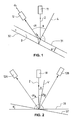
- the reference numeral 3 refers to a simplified schematic representation of an optically scattering body, in particular a cornea, with the refractive index n and the thickness d.
- a light projector 11 projects a beam 2 through the cornea 3.
- a cross-sectional part of the cornea 3 is illuminated.
- the reference numeral 4 designates a surface normal to the surface 31 of the cornea 3.
- the angle of incidence ⁇ indicates the angle between the beam 2 and the surface normal 4.
- the reference numeral 12 designates an image sensing device having processing means which detects the cross-sectional part illuminated in the cornea 3 at an observation angle ⁇ .
- the path lengths of the light rays traveled in a transparent body, in this case the cornea 3 depend on the refractive indices of the transparent body and the surrounding medium as well as on the angle of incidence and the angle of reflection of the light rays.
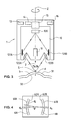
- the device arrangement shown in FIG. 2 comprises two image acquisition devices 12A and 12B, for example CCD cameras (Charged Coupled Device) or CMOS cameras (Complementary Metal-Oxide-Silicon).
- image acquisition device 12A the cross-sectional part of the cornea illuminated by the light projector 11 is detected and imaged at the observation angle ⁇ A.
- image acquisition device 12B the cross-sectional part of the cornea illuminated by the light projector 11 is detected and imaged at the observation angle ⁇ B.
- the light projector 11 projects the beam 2 preferably in the form of a light plane, in particular as a projected light slit, so that a light section results as the illuminated cross-sectional part.
- the beam 2 may also have a beam-shaped structure.
- the light projector 11 includes, for example, a slit lamp or a laser whose light is shaped into a fan by beam-shaping optics.
- the observation angles ⁇ A and ⁇ B can be different and can also be on the same side of the beam.
- the two image capture devices 12A and 12B are preferably positioned in a common plane perpendicular to the light plane. As shown schematically in FIG. 2, the beam 2 of the light projector 11 is projected perpendicularly (with respect to the plane of the drawing) to the corneal surface 31 through the cornea.
- the radiation beam 2 is tilted by the corresponding angle of incidence ⁇ from the surface normal 4' to the inclined corneal surface 31 '.
- the distance d A between the front and back corneal surface from the image of the image capture device 12A, and the distance d B between the front and back corneal surface from the image capture device image 12B, determine. Since the observation angles ⁇ A and ⁇ B are known from the geometry of the device arrangement and since the refractive index n is also known, there are two equations (i) with two unknowns for calculating the thickness d of the actual cornea and the angle of incidence ⁇ corresponding to the surface inclination angle ⁇ corresponds to the cornea.
- the two image capture devices 12A and 12B are arranged so that the viewing angles ⁇ A and ⁇ B are the same amount and that is projected approximately perpendicular to the corneal surface 31.
- a planned vertical projection of the radiation beam 2 through the vertex S of the cornea results in a lateral displacement of the vertex S (that is, an eccentricity) of one millimeter
- these are replaced by the corresponding surface inclination angle ⁇ measurement deviations caused at the shifted measurement point, compared to a measurement with only one image capture device 12 from a position by at least a factor of ten reduced.
- the measurement deviations with eccentricity up to one millimeter (or with corresponding tilting) are kept well below five micrometers.
- the reference numeral 1 designates a preferred embodiment of the device for determining geometric measured values of an eye.
- the elements provided with the same reference numbers in FIG. 3 correspond to those of the device arrangement of FIG. 2.
- the device 1 is applied such that the radiation beam 2 from the light projector 11 is substantially perpendicular to the front corneal surface 31 through the vertex S of the cornea 3 is projected.
- the cross-sectional part of the cornea 3 illuminated by the radiation beam 2 is detected and imaged by the device 1 from two different positions.
- the image capture means of the device 1 differ from those in the device arrangement of FIG. 2 in that they comprise only a single image converter 120.
- the image capturing means of the apparatus 1 further comprise beam imaging optical elements 122A and 122B, for example lenses or lenses, and beam deflecting optical elements 121A and 121B, for example mirrors.
- a radiant imaging element 122A, respectively 122B and a beam-deflecting element are respectively 121A, respectively 121B arranged in pairs such that light rays of the illuminated cross-sectional portion of the cornea 3 with a viewing angle ⁇ A, respectively, ⁇ B through the jet imaging elements 122A respectively 122B in the direction of the beam deflecting elements 121A and 121B respectively, and that these light beams are deflected by the beam deflecting elements 121A and 121B, respectively, to the common image converter 120.
- the observation angles ⁇ A and ⁇ B are preferably the same amount.
- the beam imaging elements 122A and 122B and the beam deflecting elements 121A and 121B are preferably arranged symmetrically (to the optical axis Z of the eye) in a plane perpendicular to the plane of light.
- the image converter 120 for example a CCD chip, is preferably arranged in Scheimpflug arrangement to the radiation beam 2. It will be understood by those skilled in the art that the arrangement of optical elements shown in Figure 3 is only one of many possible arrangements to form two images of at least a portion of the cross-sectional portion of the cornea 3 illuminated by the light projector 11 at two viewing angles ⁇ A and ⁇ B a common image converter 120 to produce. For example, it would also be possible to arrange mirrors in front of the lenses, to use further mirrors and lenses, to use mirror optics and / or to arrange the optical elements asymmetrically and to use anamorphic images.
- a double image with a first under the observation angle ⁇ A recorded image 6 A of the illuminated cross-sectional part of the cornea 3 and a second under the observation angle ⁇ B recorded image 6 B of the illuminated cross-sectional part of the cornea 3 is generated, as shown in Figure 4 schematically a light section is displayed.
- d A indicates that the thickness of the cornea may seem to be tapering towards the edge due to the laws of image formation. This apparent change in thickness can be taken into account in the calculation of the actual thickness of the cornea 3, for example, by determining the angle ⁇ to the plane of symmetry of the light section.
- a correction function as a function of the angle ⁇ can then correct the determined thickness values.
- the apparatus 1 comprises image processing means 13 with programmed software modules which control a processor of the apparatus 1 to perform the image processing functions described below.
- the image processing means 13 respectively determine eye structures defined from the acquired first image 6A and the acquired second image 6B, such as the cornea determined by the image of the anterior corneal surface 61A and 61B and the image of the posterior corneal surface 62A and 62B, respectively, or the outline of the iris and the pupil (not shown), or other features such as anterior chamber depth or anterior chamber angle (not shown).
- the image processing means determine 13 defined distances between the determined imaged eye structures, such as the corneal thickness, that is, the distance d A between the image of the anterior corneal surface 61A and the image of the posterior corneal surface 62A, respectively, the distance d B between the image of the anterior corneal surface 61B, and the image of the posterior corneal surface 62B.
- FIG. 4 shows a preferred embodiment in which the distances are determined directly in the image of the cornea.
- the device 1 comprises processing means 14 with programmed software modules which control a processor of the device 1 to perform the functions described below.
- the processing means 14 calculate geometric measurements of the eye from the distances determined by the image processing means 13, such as distances between the actual structures of the eye, in particular the corneal thickness d, or the surface inclination angle ⁇ of the cornea 3.
- the processing means 14 calculate from the distance d A and the distance d B by weighted averaging the corneal thickness d.
- the weighting factors for the averaging result from the equation (i) with known refractive index n and at known observation angles.
- the processing means 14 can also be designed such that they calculate the surface inclination angle ⁇ of the cornea 3 from the distance d A and the distance d B , which, as already mentioned, corresponds to the angle of incidence ⁇ between the radiation beam 2 and a surface normal 4 to the front corneal surface 31 ,
- the processing means 14 also calculate from the distance d A and the distance d B a tilting factor k according to the equation (vi), which determines the extent of the tilting of the beam 2 with respect to the surface normal 4 to the front corneal surface 31 (or the extent of the eccentricity) and / or the extent of the deviation of the observation angle ⁇ A from the observation angle ⁇ B indicates.
- k d B - d A d B + d A
- the processing means 14 use the weighted averaging for calculating the corneal thickness d without the adaptation of the corneal thickness d Weighting factors on the tilting.
- the weighting factors can be as a function of the tilt factor.
- the processing means 14 show the Verkippungs tone k as an application aid for the user of the device 1 on the display 16.
- the tilt factor k can also be achieved by the processing means 14 in the calculation of the corneal thickness d as a basis for the decision for the automatic switching from a first weighted calculation mode Averaging to be used for a second calculation mode in which in addition to the corneal thickness d and the angle of incidence ⁇ respectively the surface inclination angle ⁇ of the cornea is assumed to be unknown and two equations (i) for the two Image capture devices 12A and 12B, respectively for the corresponding ones Image acquisition means 120, 121A, 121B, 122A, 122B.
- the processing means 14 may be the thickness of the cornea 3 and the Surface inclination angle ⁇ for all points of the anterior surface of the cornea 31 in the detected sub-area of the illuminated cross-section the cornea 3 is located.
- a rotation driver 15 for example an electric motor
- the image processing means 13 and the processing means 14 comprise programmed software modules running on a common processor or run on multiple processors.
- image processing means 13 and Processing means 14 purely conceptual nature, that is functions the the Image processing means 13 could also be the processing means 14 and vice versa (such as the determination of distances).
- the skilled person will understand that the functions of Software modules of the image processing means 13 and the processing means 14th can also be executed in hardware.
- the device 1 is preferably is designed as a compact test sample, with the for the nationwide Calculation of the corneal thickness d and the surface inclination angle ⁇ competent modules of the processing means 14 in an external processing unit, for example, in a personal computer can, wherein the data exchange with the device 1 via a contact or contactless communication connection takes place. calculated values
- the corneal thickness d and the surface inclination angle ⁇ can be determined on the Display 16 or displayed on a display of the external processing unit become.
- the device 1 can be extended to the projection of multiple beams.
- images from more than two observation angles could also be detected, but this only makes sense if additional parameters, such as the width of the radiation beam, are to be recorded (three equations with three unknowns).
- the observation angle ⁇ ( ⁇ A , ⁇ B ) used in the description is representative of an observation beam. If central perspective images are used then ⁇ varies.
Abstract
Description
Die vorliegende Erfindung betrifft eine Vorrichtung und ein Verfahren zur Bestimmung von geometrischen Messwerten eines Auges. Die Erfindung betrifft insbesondere eine Vorrichtung und ein Verfahren zur Bestimmung von geometrischen Messwerten eines menschlichen Auges, in welchen mittels eines Lichtprojektors ein Strahlenbündel durch einen Querschnittsteil des Auges projiziert wird, in welchen mittels Bilderfassungsmitteln ein erstes Abbild von mindestens einem Teilgebiet des durch den Lichtprojektor beleuchteten Querschnittsteils unter einem ersten Beobachtungswinkel, aus einer ersten Position ausserhalb des Strahlenbündels erfasst wird, und in welchen mittels der Bilderfassungsmittel ein zweites Abbild des Teilgebiets unter einem zweiten Beobachtungswinkel, aus einer zweiten Position ausserhalb des Strahlenbündels erfasst wird.The present invention relates to an apparatus and a method for determining geometric measurements of an eye. The invention more particularly relates to an apparatus and a method for determining geometric measurements of a human eye, in which by means of a Light projector a beam through a cross-sectional part of the eye is projected in which means of image acquisition means a first image of at least a portion of the lit by the light projector cross-section part at a first viewing angle, from a first position is detected outside the beam, and in which by means of the image capture means a second image of the sub-area at a second observation angle, from a second position outside the beam is detected.
In der Patentschrift US 6,234,631 wird ein Verfahren zur Vermessung der hinteren und vorderen Hornhautoberfläche und der Hornhautdicke des Auges beschrieben. Im Verfahren gemäss US 6,234,631 werden eine frontale Kamera zur Aufnahme einer Frontalansicht und symmetrisch dazu eine linke und eine rechte Kamera zur Aufnahme von zwei Seitenansichten des Auges verwendet. Die linke und die rechte Kamera sind jeweils in einem 45-Grad-Winkel zur optischen Achse der frontalen Kamera orientiert. Im Verfahren gemäss US 6,234,631 wird ein Lichtmuster in der Form eines Kreuzes, ähnlich wie zwei senkrecht zueinander stehende Lichtspalten, auf die Hornhaut projiziert und die Iris des Auges wird zur Kontrastierung der Pupille mit Infrarotlicht beleuchtet. Mit der frontalen Kamera wird der horizontale Teil des Lichtkreuzes und mit der linken und der rechten Kamera wird jeweils der vertikale Teil des Lichtkreuzes aufgenommen. Gleichzeitig wird durch jede der drei Kameras ein Bild der Pupille aufgenommen. Aus den Pupillenbildern wird der Pupillenumriss aus der Sicht jeder der drei Kameras bestimmt. Aus den Aufnahmen des Lichtkreuzes und unter Annahme einer ungefähren Hornhautoberfläche wird gemäss US 6,234,631 auf der Grundlage des Strahlengangs Lichtquelle-Hornhaut-Kamera, mittels so genanntem Ray Tracing, ein erster Näherungswert für die Hornhautdicke berechnet. Dieser erste Näherungswert dient als Ausgangswert für ein iteratives Verfahren, in welchem ausgehend von der vorgängig bestimmten Topographie der vorderen Hornhautoberfläche die Hornhautdicke und die Topographie der hinteren Hornhautoberfläche bestimmt wird. Die Bestimmung der Topographie der vorderen Hornhautoberfläche erfolgt durch iterative Berechnung aus Aufnahmen von Spiegelungen einer Placidoscheibe auf der Hornhaut, die mittels der drei Kameras aufgenommen werden. Die Hornhautdicke und die Topographie der hinteren Hornhautoberfläche werden gemäss US 6,234,631 iterativ auf der Grundlage des Strahlengangs Pupillenumriss-Hornhaut-Kamera berechnet (Ray Tracing), wobei die Ansichten von jeder der drei Kameras berücksichtigt werden.US Pat. No. 6,234,631 describes a method for measuring the posterior and anterior corneal surface and corneal thickness of the eye. In the process according to US 6,234,631 a Frontal camera to take a frontal view and symmetrical to one left and right camera to take two side views of the eye used. The left and right cameras are each at a 45-degree angle oriented to the optical axis of the frontal camera. In the process according to US 6,234,631 will be a light pattern in the shape of a cross, similar like two perpendicular columns of light, projected onto the cornea and the iris of the eye becomes the contrast of the pupil with infrared light illuminated. The frontal camera becomes the horizontal part of the cross of light and with the left and right camera respectively the vertical part of the Light Cross recorded. At the same time, each of the three cameras will turn on Picture of the pupil taken. The pupil images become the pupil outline determined from the point of view of each of the three cameras. From the footage of the Cross of Light and assuming an approximate corneal surface is determined according to US 6,234,631 on the basis of the beam source light source cornea camera, using so-called ray tracing, a first approximation for the corneal thickness is calculated. This first approximation value serves as the output value for an iterative procedure in which, starting from the previous one determined topography of the anterior corneal surface the corneal thickness and the topography of the posterior corneal surface is determined. The Determination of the topography of the anterior corneal surface is carried out by iterative calculation from images of reflections of a Placido disk on the cornea taken by the three cameras. The Corneal thickness and the topography of the posterior corneal surface according to US 6,234,631 iteratively on the basis of the beam path Pupil outline cornea camera calculates (ray tracing), taking the views be considered by each of the three cameras.
In der Patentanmeldung WO 01/62140 wird ein System für die Messung der Topographie der beiden Hornhautoberflächen und der Hornhautdicke beschrieben. Im System gemäss WO 01/62140 wird ein Lichtstrahl, beispielsweise ein Laserstrahl, mittels einer zylinderförmigen Linse fächerförmig ausgeweitet und auf die Hornhaut des Auges gestrahlt. Das System ist so eingerichtet, dass der fächerförmige Lichtstrahl rotiert werden kann. Das beleuchtete Gebiet im Schnittbereich des fächerförmigen Lichtstrahls und der Hornhaut wird durch zwei Kameras aufgenommen, die rechtwinklig zueinander angeordnet sind, so dass ihre Beobachtungsrichtungen in der Blickrichtung der optischen Achse des Auges einen 90-Grad-Winkel einschliessen. Die durch die Kameras aufgenommen Bilder des beleuchteten Schnittbereichs sind jeweils nur dann unverzerrt, wenn die Ebene des Schnittbereichs senkrecht (in Richtung der optischen Achse des Auges gesehen) zu der Beobachtungsrichtung der betreffenden Kamera liegt. Die andere Kamera erfasst in dieser Position den Schnittbereich in Aufsicht und kann somit weder die Dicke noch das Profil der Hornhaut erfassen. Im System gemäss WO 01/62140 wird aus den Aufnahmen der beiden Kameras ein korrigiertes, unverzerrtes Bild erzeugt, wobei das unverzerrte Bild dem einer virtuellen rotierenden Kamera entspricht. Aus dem korrigierten Bild wird dann die Dicke der Hornhaut bestimmt. Durch Rotation der Lichtquelle kann die Hornhauttopographie aus mehreren korrigierten Bildern zusammengesetzt werden. In the patent application WO 01/62140 a system for the measurement the topography of the two corneal surfaces and the corneal thickness described. In the system according to WO 01/62140 a light beam, for example a laser beam, fan-shaped by means of a cylindrical lens and blasted onto the cornea of the eye. The system is set up that the fan-shaped light beam can be rotated. The lit up Area in the intersection of the fan-shaped light beam and the cornea is taken by two cameras arranged at right angles to each other are, so their directions of observation in the line of sight of the optical Axis of the eye at a 90 degree angle. The through the cameras taken pictures of the illuminated section are each only then undistorted, if the plane of the cutting area is perpendicular (in the direction of optical axis of the eye) to the observation direction of the camera is concerned. The other camera captures the position in this position Section in supervision and can therefore neither the thickness nor the profile of the Capture the cornea. In the system according to WO 01/62140 is from the recordings the two cameras produced a corrected, undistorted image, the undistorted image that corresponds to a virtual rotating camera. From the corrected image is then determined the thickness of the cornea. By rotation The light source can make the corneal topography from multiple corrected images be assembled.
Zur Berechnung der Hornhautdicke mittels Ray Tracing muss neben dem Brechungsindex der Hornhaut, dem Beleuchtungswinkel (Richtungen der projizierten Lichtstrahlen), dem Beobachtungswinkel (Richtung der aufgenommenen Lichtstrahlen) auch die Oberflächenneigung der Hornhaut bekannt sein. Der Brechungsindex kann als bekannt angenommen werden und sowohl der Beleuchtungs- als auch der Beobachtungswinkel kann durch Kalibrierung des Systems gemäss WO 01/62140 bestimmt werden; für die Bestimmung der Oberflächenneigung benötigt das System gemäss WO 01/62140 allerdings zusätzliche Mittel, wenn der Einfluss der Oberflächenneigung der Hornhaut das Resultat der Dickenberechnung gemäss WO 01/62140 nicht verfälschen soll.To calculate the corneal thickness by means of ray tracing must beside the refractive index of the cornea, the illumination angle (directions of the projected light rays), the observation angle (direction of the recorded Light rays), the surface inclination of the cornea may also be known. The refractive index can be assumed to be known and both the Illumination angle as well as the observation angle can be adjusted by calibration of the Systems are determined according to WO 01/62140; for the determination of Surface tilt requires the system according to WO 01/62140, however, additional Means, when the influence of the surface slope of the cornea that Result of the thickness calculation according to WO 01/62140 should not falsify.
Es ist eine Aufgabe der vorliegenden Erfindung, eine neue Vorrichtung und ein neues Verfahren zur Bestimmung von geometrischen Messwerten eines Auges vorzuschlagen, deren Ausführung einfacher als die im Stand der Technik ist und die insbesondere keine zusätzlichen, speziellen Mittel zur Bestimmung der Oberflächenneigung der Hornhaut des Auges benötigen.It is an object of the present invention to provide a new device and a new method for determining geometric measurements to propose an eye whose execution is simpler than that in the state of Technique is and in particular no additional, special means of determination the surface inclination of the cornea of the eye need.
Gemäss der vorliegenden Erfindung werden diese Ziele insbesondere durch die Elemente der unabhängigen Ansprüche erreicht. Weitere vorteilhafte Ausführungsformen gehen ausserdem aus den abhängigen Ansprüchen und der Beschreibung hervor.According to the present invention, these objects become particular achieved by the elements of the independent claims. Further advantageous Embodiments are further subject to the dependent claims and the description.
Die Vorrichtung zur Bestimmung von geometrischen Messwerten eines Auges, insbesondere eines menschlichen Auges, umfasst einen Lichtprojektor zur Projektion eines Strahlenbündels durch einen Querschnittsteil des Auges, und Bilderfassungsmittel zur Erfassung eines ersten Abbilds von mindestens einem Teilgebiet des durch den Lichtprojektor beleuchteten Querschnittsteils unter einem ersten Beobachtungswinkel, aus einer ersten Position ausserhalb des Strahlenbündels, und zur Erfassung eines zweiten Abbilds des Teilgebiets unter einem zweiten Beobachtungswinkel, aus einer zweiten Position ausserhalb des Strahlenbündels.The device for determining geometric measured values of a Eye, especially a human eye, includes a light projector for projecting a beam through a cross - section of the beam Eye, and image capture means for capturing a first image of at least a subregion of the illuminated by the light projector cross-section part at a first viewing angle, from a first position outside the beam, and to capture a second image of the Subarea at a second observation angle, from a second position outside the beam.
Die oben genannten Ziele werden durch die Erfindung insbesondere dadurch erreicht, dass diese Vorrichtung Bildverarbeitungsmittel umfasst zur Bestimmung von Augenstrukturen aus dem erfassten ersten Abbild, zur Bestimmung von Augenstrukturen aus dem erfassten zweiten Abbild, zur Bestimmung einer ersten Distanz zwischen den aus dem ersten Abbild bestimmten Augenstrukturen, und zur Bestimmung einer zweiten Distanz zwischen den aus dem zweiten Abbild bestimmten Augenstrukturen, und dass diese Vorrichtung Verarbeitungsmittel zur Berechnung von mindestens einem der geometrischen Messwerte direkt aus der bestimmten ersten Distanz und der bestimmten zweiten Distanz umfasst.The above objects are achieved by the invention in particular achieved in that this device comprises image processing means for Determination of eye structures from the recorded first image, to Determination of eye structures from the acquired second image, for Determining a first distance between the first image certain eye structures, and to determine a second distance between the eye structures determined from the second image, and that this device processing means for calculating at least one the geometric measurements directly from the specific first distance and the certain second distance.
Mit der Bestimmung der ersten und zweiten Distanz aus zwei Abbildern des beleuchteten Querschnittsteils, z.B. ein so genannter Lichtschnitt, aus zwei unabhängigen Positionen mit bekannten Beobachtungswinkeln, ergeben sich bei bekanntem Brechungsindex zwei Gleichungen mit zwei Unbekannten, die sich aus diesen Gleichungen berechnen lassen, nämlich der Oberflächenneigungswinkel der Hornhaut und die Distanz zwischen den abgebildeten Augenstrukturen entsprechenden tatsächlichen Strukturen im Auge. Der Vorteil der derart eingerichteten Vorrichtung zur Bestimmung von Distanzen zwischen Augenstrukturen und Oberflächenneigungswinkel der Hornhaut als geometrische Messwerte eines Auges besteht insbesondere in ihrer Einfachheit. Ein weiterer Vorteil dieser Vorrichtung besteht darin, dass für die Bestimmung von Distanzen zwischen Augenstrukturen keine Schätzungen oder Annahmen über den Oberflächenneigungswinkel der Hornhaut des Auges gemacht werden müssen. Damit lässt sich beispielsweise auch ein aufgeklappter Hornhautlappen, also ein Stück Hornhaut in beliebiger Lage, messen. Die Vorrichtung benötigt weder zusätzliche spezielle Mittel zur Bestimmung der Oberflächenneigung der Hornhaut noch zahlreiche Kameras oder spezielle zusätzliche Infrarotlichtquellen und sie benötigt auch keine zahlreichen Iterationsschritte, welche sowohl Zeit als auch Rechenleistung und Speicherplatz erfordern. Da die Augenstrukturen aus zwei Beobachtungswinkeln erfasst werden, kann die Bestimmung von geometrischen Messwerten auch erfolgen, wenn eines der beiden Abbilder ausnahmsweise abgeschattet ist.With the determination of the first and second distance from two images the illuminated cross-section part, e.g. a so-called light section, off two independent positions with known viewing angles with known refractive index two equations with two unknowns, which can be calculated from these equations, namely the surface tilt angle the cornea and the distance between the imaged eye structures corresponding actual structures in mind. The advantage the device thus arranged for the determination of distances between Eye structures and surface tilt angle of the cornea as geometric Measurements of an eye is in particular in its simplicity. One Another advantage of this device is that for the determination of Distances between eye structures no estimates or assumptions about the surface tilt angle of the cornea of the eye can be made have to. This also makes it possible, for example, for an opened up corneal flap, so a piece of cornea in any position, measure. The device is needed neither additional special means for determining surface tilt the cornea still numerous cameras or special additional infrared light sources and it does not need many iteration steps, which both time and computing power and disk space require. Because the Eye structures can be detected from two observation angles, the determination of geometric readings also take place when one of the two Image is exceptionally shadowed.
In einer bevorzugten Ausführungsvariante sind die Verarbeitungsmittel der Vorrichtung eingerichtet zur Berechnung der Distanz zwischen den tatsächlichen Augenstrukturen, das heisst zwischen den Strukturen im Auge, die den aus dem ersten und aus dem zweiten Abbild bestimmten Augenstrukturen entsprechen, aus der bestimmten ersten Distanz und der bestimmten zweiten Distanz, vorzugsweise durch gewichtete Mittelwertbildung aus der bestimmten ersten Distanz und der bestimmten zweiten Distanz.In a preferred embodiment, the processing means the device set up to calculate the distance between the actual eye structures, that means between the structures in the eye, the ones determined from the first and the second image Eye structures correspond, from the specific first distance and the certain second distance, preferably by weighted averaging from the determined first distance and the determined second distance.
Vorzugsweise sind die Bildverarbeitungsmittel eingerichtet zur Bestimmung der Hornhaut des Auges aus dem erfassten ersten Abbild, zur Bestimmung der Hornhaut des Auges aus dem erfassten zweiten Abbild, zur Bestimmung einer ersten Distanz der aus dem ersten Abbild bestimmten Hornhaut, und zur Bestimmung einer zweiten Distanz der aus dem zweiten Abbild bestimmten Hornhaut, und die Verarbeitungsmittel sind eingerichtet zur Berechnung der Dicke der tatsächlichen Hornhaut des Auges aus der bestimmten ersten Distanz und der bestimmten zweiten Distanz. Die oben genannten Vorteile können so bei einer entsprechenden Vorrichtung zur Messung der Hornhautdicke erreicht werden.Preferably, the image processing means are set up for Determination of the cornea of the eye from the recorded first image, to Determination of the cornea of the eye from the captured second image, to Determining a first distance of the one determined from the first image Cornea, and to determine a second distance from that of the second Image specific cornea, and the processing means are set up for Calculation of the thickness of the actual cornea of the eye from the certain first distance and the determined second distance. The above mentioned advantages can be so in a corresponding device for measurement the corneal thickness can be achieved.
In einer bevorzugten Ausführungsvariante sind die Verarbeitungsmittel zusätzlich oder als Alternative eingerichtet zur Berechnung eines Neigungswinkels zwischen dem Strahlenbündel und der Normalen zu der dem Lichtprojektor zugewandten Oberfläche der tatsächlichen Hornhaut des Auges aus der bestimmten ersten Distanz und der bestimmten zweiten Distanz. Die Vorrichtung kann so nicht nur zur Messung von Distanzen zwischen Augenstrukturen, insbesondere zur Messung der Hornhautdicke, sondern auch zur Messung der Oberflächenneigung der Hornhaut verwendet werden.In a preferred embodiment, the processing means additionally or alternatively set up to calculate a tilt angle between the beam and the normal to the Light projector facing surface of the actual cornea of the eye from the determined first distance and the determined second distance. The Device can not only measure distances between Eye structures, in particular for measuring corneal thickness, but also be used to measure the surface inclination of the cornea.
Vorzugsweise liegen die erste Position und die zweite Position der Bilderfassungsmittel auf verschiedenen Seiten einer durch das Strahlenbündel gelegten Ebene und der erste und der zweite Beobachtungswinkel sind gleich gross. Der Vorteil, die beiden Beobachtungswinkel gleich gross zu wählen, besteht darin, dass eine genaue Bestimmung der Oberflächenneigung der Hornhaut nicht nötig ist, da sich kleine Abweichungen von einer angenommenen oder geschätzten Oberflächenneigung nicht auf den aus der bestimmten ersten Distanz und der bestimmten zweiten Distanz berechneten Mittelwert auswirken, wenn die Vorrichtung so appliziert wird, dass das Strahlenbündel näherungsweise durch einen Meridianschnitt der Hornhaut geht. Bei der Mittelwertbildung heben sich nämlich die Abweichungen bei der Bestimmung der ersten Distanz zwischen den Augenstrukturen aus dem ersten Abbild und der zweiten Distanz zwischen den Augenstrukturen aus dem zweiten Abbild gegenseitig auf. Das heisst, die Abweichungen der aus zwei verschiedenen Perspektiven bestimmten Distanzen heben sich gegenseitig auf. Wenn folglich die Vorrichtung so angewendet wird, dass das Strahlenbündel im Wesentlichen senkrecht zu der dem Lichtprojektor zugewandten (Hornhaut-) Oberfläche des Auges projiziert wird, wirken sich geringe Verkippungen des Strahlenbündels bezüglich der Normalen zu der dem Lichtprojektor zugewandten Oberfläche der Hornhaut nicht auf die Bestimmung der Hornhautdicke aus. Auch wenn die Vorrichtung so angewendet wird, dass das Strahlenbündel im Wesentlichen senkrecht durch den Scheitelpunkt der Hornhaut projiziert wird (das heisst durch die optische Achse des Auges), wirken sich geringe Verkippungen (das heisst Neigung von der Normalen) und Exzentrizitäten (das heisst Verschiebungen vom Scheitelpunkt) des Strahlenbündels nicht auf die Bestimmung der Hornhautdicke aus. Dasselbe trifft auf kleine Abweichungen des ersten Beobachtungswinkels vom zweiten Beobachtungswinkel zu. Auch Verkippungen des Lichtprojektors wirken sich weniger kritisch auf die Messung aus. Der Vorteil gleicher Beobachtungswinkel besteht also darin, dass sich kleine Ungenauigkeiten bei der Applikation, der Justierung und/oder der Kalibrierung der Vorrichtung ohne grosse Abweichungen auf die Messresultate auswirken. Wird die Vorrichtung beispielsweise in Meridianschnitten appliziert, dann reicht eine Kalibrierung im Meridianschnitt aus, um auch bei leichten Exzentrizitäten und Verkippungen genau messen zu können. Die Vorrichtung ermöglicht so eine einfachere Applikation und Ausführung unter Beibehaltung der Genauigkeit der Messresultate.Preferably, the first position and the second position are the Image capture means on different sides of a through the beam level and the first and second observation angles are the same large. The advantage of choosing the two observation angles the same size exists in that an accurate determination of the surface inclination of the cornea is not necessary, since small deviations from an assumed or estimated surface slope does not depend on the one out of the particular first one Distance and the calculated second distance calculated average, when the device is applied so that the beam approximately through a meridian section of the cornea. In the Averaging, namely, the deviations in determining cancel the first distance between the eye structures from the first image and the second distance between the eye structures from the second image each other up. That is, the deviations of two different Perspectives of certain distances cancel each other out. If therefore the device is applied so that the beam substantially perpendicular to the light projector facing (corneal) surface of the When the eye is projected, slight tilting of the beam will result with respect to the normal to the light projector facing surface of Cornea does not depend on the determination of corneal thickness. Even if the Device is applied so that the beam substantially is projected vertically through the apex of the cornea (ie through the optical axis of the eye), small tiltings (the means inclination of the normal) and eccentricities (that is Shifts from the vertex) of the beam not on the Determination of corneal thickness. The same applies to small deviations of the first viewing angle from the second viewing angle. Also Tilting the light projector is less critical to the measurement out. The advantage of the same observation angle is that small inaccuracies in the application, the adjustment and / or the Calibration of the device without major deviations on the measurement results impact. If the device is applied, for example, in meridian sections, then a calibration in the meridian section is sufficient, even with slight eccentricities and accurately measure tilting. The device thus allows easier application and execution while maintaining the accuracy of the measurement results.
In einer Ausführungsvariante sind die Verarbeitungsmittel eingerichtet zur Berechnung eines Verkippungsfaktors aus der bestimmten ersten Distanz und der bestimmten zweiten Distanz, welcher Verkippungsfaktor das Ausmass der Verkippung des Strahlenbündels bezüglich der Normalen zu der dem Lichtprojektor zugewandten Oberfläche der tatsächlichen Hornhaut des Auges und das Ausmass der Abweichung des ersten Beobachtungswinkels vom zweiten Beobachtungswinkel angibt. Ein solcher Verkippungsfaktor gibt ein Mass für die Güte der Applikation und der Genauigkeit der Messung. Der Verkippungsfaktor kann dem Benutzer der Vorrichtung angezeigt werden, so dass eine Korrektur der Applikation oder der Kalibrierung der Vorrichtung vorgenommen werden kann. Die Verarbeitungsmittel können auch so eingerichtet sein, dass sie in Abhängigkeit des bestimmten Verkippungsfaktors Gewichtungsfaktoren für die Mittelwertbildung bestimmen, so dass die Bestimmung der Messwerte automatisch an das Ausmass der Verkippung des Strahlenbündels, an das Ausmass der Abweichung des ersten Beobachtungswinkels vom zweiten Beobachtungswinkel und/oder an die Oberflächenneigung der Hornhaut angepasst wird.In one embodiment, the processing means are set up for calculating a tilt factor from the determined first one Distance and the determined second distance, which tilting factor that Extent of tilt of the beam with respect to the normal to the the light projector facing surface of the actual cornea of the Eye and the extent of deviation of the first observation angle indicating from the second observation angle. Such a tilt factor gives a measure of the quality of the application and the accuracy of the measurement. Of the Tilt factor can be displayed to the user of the device, so that is a correction of the application or calibration of the device can be made. The processing means can do that too be set up that they depend on the specific tilt factor Determine weighting factors for averaging, so that the Determination of the measured values automatically to the extent of the tilting of the Beam, to the extent of the deviation of the first Observation angle from the second observation angle and / or to the Surface inclination of the cornea is adjusted.
In einer bevorzugten Ausführungsvariante umfassen die Bilderfassungsmittel einen Bildwandler, z.B. einen CCD-Chip (Charged Coupled Device) einer Kamera, und die Bilderfassungsmittel umfassen optische Elemente zur Lichtstrahlumlenkung, wobei erste der optischen Mittel so bei der ersten Position angeordnet sind, dass Lichtstrahlen zur Erzeugung des ersten Abbilds zum Bildwandler umgelenkt werden und wobei zweite der optischen Mittel so bei der zweiten Position angeordnet sind, dass Lichtstrahlen zur Erzeugung des zweiten Abbilds zum Bildwandler umgelenkt werden. Der Vorteil derart angeordneter optischer Mittel zur Lichtstrahlumlenkung besteht darin, dass das erste und das zweite Abbild, das heisst die Aufnahme zweier Perspektiven des Lichtschnitts, zeitgleich mit einer einzigen gemeinsamen Kamera erfasst werden kann. Dadurch kann auf eine zweite kostspielige Kamera und Bilderfassungshardware verzichtet werden, es erübrigt sich die Synchronisation mehrerer Bildwandler und es ergibt sich eine besonders kompakte Vorrichtung.In a preferred embodiment, the image capture means comprise an image converter, e.g. a CCD chip (Charged Coupled Device) a camera, and the image acquisition means comprise optical elements for Light beam deflection, wherein the first of the optical means so at the first position are arranged that light rays for generating the first image to Image converter to be deflected and wherein second of the optical means so in the second position are arranged, that light beams for generating the second Image to be deflected to the image converter. The advantage of such arranged optical means for light beam deflection is that the first and the second image, that is the recording of two perspectives of the light section, be captured simultaneously with a single common camera can. This allows for a second expensive camera and image capture hardware be dispensed with, it is unnecessary to synchronize several Image converter and there is a particularly compact device.
Vorzugsweise ist der Lichtprojektor so beschaffen, dass er das Strahlenbündel in Form einer Lichtebene projiziert. Die Lichtebene, beispielsweise in Form eines projizierten Lichtspalts, eignet sich besonders gut für die Erzeugung eines beleuchteten Lichtschnitts im Auge, der von zwei verschiedenen Positionen bildlich so erfasst werden kann, das sich entsprechende Augenstrukturen in den beiden Abbildern einander leicht zuordnen lassen.Preferably, the light projector is adapted to receive the Beam projected in the form of a plane of light. The light plane, for example in the form of a projected light gap, is particularly suitable for the Generation of an illuminated light section in the eye, that of two different positions can be figuratively captured that himself corresponding eye structures in the two images each other easily can be assigned.
Vorzugsweise sind die Bilderfassungsmittel in Scheimpfluganordnung zum Strahlenbündel angeordnet. Die Scheimpfluganordnung der Bilderfassungsmittel hat den Vorteil, dass entlang des Strahlenbündels über einen grossen Bereich scharf abgebildet wird.Preferably, the image capture means are in Scheimpflug arrangement arranged to the beam. The Scheimpflug arrangement of image capture devices has the advantage that along the beam over a large area is sharply displayed.
In einer Ausführungsvariante umfasst die Vorrichtung einen Rotationstreiber zum Rotieren der Bilderfassungsmittel und des Lichtprojektors um eine durch das Strahlenbündel verlaufende Achse. Durch die Rotation der Bilderfassungsmittel und des Lichtprojektors vorzugsweise um die optische Achse des Auges können geometrische Messwerte, insbesondere die Hornhautdicke, des ganzen Auges bestimmt werden. Dabei wirken sich der hohe Grad an Symmetrie und die gleich bleibenden Messbedingungen bei der Rotation um die optische Achse des Auges positiv auf die Messgenauigkeit aus.In one embodiment, the device comprises a rotation driver to rotate the image capture means and the light projector around an axis passing through the beam. By the rotation of the image capture means and the light projector preferably around the optical axis of the eye, geometrical measurements, in particular the cornea thickness, of the whole eye. This affects the high degree Symmetry and the constant measurement conditions during rotation around the optical axis of the eye has a positive effect on the measuring accuracy.
Nachfolgend wird eine Ausführung der vorliegenden Erfindung anhand
eines Beispieles beschrieben. Das Beispiel der Ausführung wird durch die
folgenden beigelegten Figuren illustriert:
In der nachfolgenden Beschreibung ist bei der Bezugnahme auf die Figuren 1 bis 3 zu beachten, dass Überlegungen, die diese Figuren betreffen, exemplarisch für die Zeichenebene gemacht werden, dass jedoch Überlegungen für Ebenen parallel zu der Zeichenebene entsprechend gelten. Der Begriff senkrecht bezieht sich auf die Zeichenebene. Bei Lichtstrahlen, die nicht in der Ebene eines Meridians der Hornhaut liegen, gibt es eine zusätzliche Strahlkomponente, die aus der Zeichenebene herauszeigt. Hierdurch ändern sich je nach optischem Aufbau die funktionalen Zusammenhänge der Bildentstehung. Da dies keine Auswirkungen auf die oben genannten Vorteile des Verfahrens hat, wird im folgenden nicht mehr gesondert darauf eingegangen.In the following description is with reference to the Figures 1 to 3 note that considerations that relate to these figures, However, considerations are made as an example for the drawing level apply to layers parallel to the drawing plane. The term vertical refers to the drawing plane. For light rays that are not in the Level of a meridian of the cornea, there is an additional Beam component pointing out of the drawing plane. Change this depending on the optical structure of the functional relationships of Image formation. As this does not affect the above benefits of the procedure will not be discussed separately received.
In der Figur 1 bezieht sich das Bezugszeichen 3 auf eine vereinfachte
schematische Darstellung eines optisch streuenden Körpers, insbesondere
eine Hornhaut, mit dem Brechungsindex n und der Dicke d. In der Figur 1
projiziert ein Lichtprojektor 11 ein Strahlenbündel 2 durch die Hornhaut 3. Entsprechend
der Struktur des Strahlenbündels 2 wird ein Querschnittsteil der
Hornhaut 3 beleuchtet. Es sei an dieser Stelle bemerkt, dass das Strahlenbündel
2 in der Praxis eine räumliche Struktur aufweist, die in der schematischen
Darstellung der Figur 1 nicht wiedergegeben ist. Mit dem Bezugszeichen 4 wird
eine Oberflächennormale zur Oberfläche 31 der Hornhaut 3 bezeichnet. Der
Einfallswinkel ⊖ gibt den Winkel zwischen dem Strahlenbündel 2 und der Oberflächennormalen
4 an. Das Bezugszeichen 12 bezeichnet eine Bilderfassungsvorrichtung
mit Verarbeitungsmitteln, welche den in der Hornhaut 3 beleuchteten
Querschnittsteil unter einem Beobachtungswinkel α erfasst. Gemäss dem
bekannten Snelliusschen Brechungsgesetz hängen die in einem transparenten
Körper, hier die Hornhaut 3, zurückgelegten Weglängen der Lichtstrahlen von
den Brechungsindizes des transparenten Körpers und des umgebenden Mediums
sowie vom Einfallswinkel und vom Ausfallswinkel der Lichtstrahlen ab.
Wird aus dem Abbild des durch den Lichtprojektor 11 beleuchteten
Querschnittsteils der Hornhaut 3, das durch die Bilderfassungsvorrichtung 12
aufgenommen wird, die Distanz d1 zwischen der abgebildeten vorderen
Hornhautoberfläche 31 und der abgebildeten hinteren Hornhautoberfläche 32
bestimmt, kann die Dicke d der tatsächlichen Hornhaut 3 folglich gemäss
analytisch oder experimentell gewonnenen Gleichungen (i) als Funktion dieser
bestimmten Distanz d1, des Einfallswinkels Θ, des Beobachtungswinkels α und
des Brechungsindex n berechnet werden (der Einfluss der Dicke des
Strahlenbündels wurde hier nicht angeführt; die Gleichung kann auch in
implizierter Form vorliegen):
Im Unterschied zu der in der Figur 1 dargestellten Vorrichtungsanordnung,
umfasst die in der Figur 2 dargestellte Vorrichtungsanordnung zwei
Bilderfassungsvorrichtungen 12A und 12B, beispielsweise CCD-Kameras
(Charged Coupled Device) oder CMOS-Kameras (Complementary Metal-Oxide-Silicon).
Durch die Bilderfassungsvorrichtung 12A wird der durch den
Lichtprojektor 11 beleuchtete Querschnittsteil der Hornhaut unter dem
Beobachtungswinkel αA erfasst und abgebildet. Durch die Bilderfassungsvorrichtung
12B wird der durch den Lichtprojektor 11 beleuchtete Querschnittsteil
der Hornhaut unter dem Beobachtungswinkel αB erfasst und abgebildet.
Der Lichtprojektor 11 projiziert das Strahlenbündel 2 vorzugsweise in
Form einer Lichtebene, insbesondere als projizierter Lichtspalt, so dass sich als
beleuchteter Querschnittsteil ein Lichtschnitt ergibt. Das Strahlenbündel 2 kann
jedoch auch eine strahlförmige Struktur haben. Der Lichtprojektor 11 umfasst
beispielsweise eine Spaltlampe oder einen Laser, dessen Licht durch Strahlumformungsoptiken
zu einem Fächer geformt wird. Die Beobachtungswinkel αA
und αB können unterschiedlich sein und sich auch auf der gleichen Seite des
Strahlenbündels befinden. Die beiden Bilderfassungsvorrichtungen 12A und
12B sind jedoch vorzugsweise in einer gemeinsamen Ebene senkrecht zu der
Lichtebene positioniert. Wie in der Figur 2 schematisch dargestellt ist, wird das
Strahlenbündel 2 des Lichtprojektors 11 senkrecht (bezogen auf die Zeichenebene)
zur Hornhautoberfläche 31 durch die Hornhaut projiziert. Weist die
Hornhautoberfläche 31' jedoch eine durch die gestrichelte Linie dargestellte
Neigung mit dem Oberflächenneigungswinkel Θ auf, so ist das Strahlenbündel
2 um den entsprechenden Einfallswinkel Θ von der Oberflächennormalen 4' zur
geneigten Hornhautoberfläche 31' verkippt.In contrast to the device arrangement illustrated in FIG. 1, the device arrangement shown in FIG. 2 comprises two
Aus den beiden Abbildern des beleuchteten Querschnittsteils der
Hornhaut aus zwei verschiedenen Positionen lassen sich die Distanz dA, zwischen
der vorderen und hinteren Hornhautoberfläche aus dem Abbild der
Bilderfassungsvorrichtung 12A, und die Distanz dB, zwischen der vorderen und
hinteren Hornhautoberfläche aus dem Abbild der Bilderfassungsvorrichtung
12B, bestimmen. Da die Beobachtungswinkel αA und αB aus der Geometrie
der Vorrichtungsanordnung bekannt sind und da der Brechungsindex n
ebenfalls bekannt ist, ergeben sich zwei Gleichungen (i) mit zwei Unbekannten
zur Berechnung der Dicke d der tatsächlichen Hornhaut und des Einfallswinkels
⊖, der dem Oberflächenneigungswinkel Θ der Hornhaut entspricht. From the two images of the illuminated cross-sectional part of the cornea from two different positions, the distance d A , between the front and back corneal surface from the image of the
Vorzugsweise werden die beiden Bilderfassungsvorrichtungen 12A
und 12B so angeordnet, dass die Beobachtungswinkel αA und αB den gleichen
Betrag haben und dass näherungsweise senkrecht zur Hornhautoberfläche 31
projiziert wird. Die Konfiguration mit gleichen Beobachtungswinkeln αA und αB
ermöglicht eine genaue Bestimmung der Dicke d der Hornhaut 3, ohne den
Oberflächenneigungswinkel Θ respektive den Einfallswinkel Θ genau bestimmen
zu müssen. Stellt man für die bestimmten Distanzen dA und dB eine Taylorreihe
gemäss den Gleichungen (iiA, iiB) auf:
In der Figur 3 bezeichnet das Bezugszeichen 1 eine bevorzugte
Ausführung der Vorrichtung zur Bestimmung von geometrischen Messwerten
eines Auges. Die mit gleichen Bezugszeichen versehenen Elemente in der Figur
3 entsprechen denjenigen der Vorrichtungsanordnung der Figur 2. In der
Figur 3 wird die Vorrichtung 1 so appliziert, dass das Strahlenbündel 2 vom
Lichtprojektor 11 im Wesentlichen senkrecht zur vorderen Hornhautoberfläche
31 durch den Scheitelpunkt S der Hornhaut 3 projiziert wird. Wie in der
Vorrichtungsanordnung gemäss der Figur 2 wird der durch das Strahlenbündel
2 beleuchtete Querschnittsteil der Hornhaut 3 durch die Vorrichtung 1 aus zwei
unterschiedlichen Positionen erfasst und abgebildet. Allerdings unterscheiden
sich die Bilderfassungsmittel der Vorrichtung 1 von denjenigen in der
Vorrichtungsanordnung der Figur 2 dadurch, dass sie nur einen (einzigen)
gemeinsamen Bildwandler 120 umfassen. Die Bilderfassungsmittel der
Vorrichtung 1 umfassen zudem strahlabbildende optische Elemente 122A und
122B, zum Beispiel Objektive oder Linsen, und strahlumlenkende optische
Elemente 121A und 121B, zum Beispiel Spiegel. Wie in der Figur 3
schematisch dargestellt ist, sind jeweils ein strahlabbildendes Element 122A
respektive 122B und ein strahlumlenkendes Element 121A respektive 121B
paarweise so angeordnet, dass Lichtstrahlen des beleuchteten
Querschnittsteils der Hornhaut 3 mit einem Beobachtungswinkel αA respektive
αB durch die strahlabbildenden Elemente 122A respektive 122B in Richtung
der strahlumlenkenden Elemente 121A respektive 121B abgebildet werden,
und dass diese Lichtstrahlen durch die strahlumlenkenden Elemente 121A respektive
121B zum gemeinsamen Bildwandler 120 umgelenkt werden. Die Beobachtungswinkel
αA und αB haben vorzugsweise den gleichen Betrag. Wie in
der Figur 3 schematisch dargestellt ist, sind die strahlabbildende Elemente
122A und 122B und die strahlumlenkenden Elemente 121A und 121B vorzugsweise
symmetrisch (zu der optischen Achse Z des Auges) in einer Ebene
senkrecht zu der Lichtebene angeordnet. Der Bildwandler 120, beispielsweise
ein CCD-Chip, ist vorzugsweise in Scheimpfluganordnung zum Strahlenbündel
2 angeordnet. Der Fachmann wird verstehen, dass die in der Figur 3
dargestellte Anordnung der optischen Elemente nur eine von vielen möglichen
Anordnungen ist, um zwei Abbilder von mindestens einem Teilgebiet des durch
den Lichtprojektor 11 beleuchteten Querschnittsteils der Hornhaut 3 unter zwei
Beobachtungswinkeln αA und αB auf einem gemeinsamen Bildwandler 120 zu
erzeugen. Es wäre beispielsweise auch möglich, Spiegel vor den Linsen
anzuordnen, weitere Spiegel und Linsen einzusetzen, Spiegeloptiken zu
verwenden und/oder die optischen Elemente asymmetrisch anzuordnen sowie
anamorphotische Abbildungen zu verwenden.In FIG. 3, the reference numeral 1 designates a preferred embodiment of the device for determining geometric measured values of an eye. The elements provided with the same reference numbers in FIG. 3 correspond to those of the device arrangement of FIG. 2. In FIG. 3, the device 1 is applied such that the
Im gemeinsamen Bildwandler 120 wird ein Doppelbild mit einem
ersten unter dem Beobachtungswinkel αA aufgenommenen Abbild 6A des beleuchteten
Querschnittsteils der Hornhaut 3 und einem zweiten unter dem Beobachtungswinkel
αB aufgenommenen Abbild 6B des beleuchteten Querschnittsteils
der Hornhaut 3 erzeugt, wie in der Figur 4 schematisch für einen
Lichtschnitt dargestellt wird. In der Figur 4 ist mit dA' angedeutet, dass die
Dicke der Hornhaut auf Grund der Gesetzmässigkeiten der Bildentstehung sich
zum Rand scheinbar verjüngen kann. Diese scheinbare Veränderung der Dicke
lässt sich bei der Berechnung der tatsächlichen Dicke der Hornhaut 3 berücksichtigen,
indem beispielsweise der Winkel γ zur Symmetrieebene des Lichtschnitts
bestimmt wird. Eine Korrekturfunktion in Abhängigkeit vom Winkel γ
kann dann die bestimmten Dickenwerte korrigieren. Damit lässt sich auf
einfache Weise eine Kalibrierung, die streng genommen nur für den
Scheitelpunkt S gültig ist, auch auf seitliche Bereiche der Hornhaut ausdehnen.
Es sei angemerkt, dass sich bei einem anders gewählten Arbeitsabstand die
beleuchteten Querschnittsteile im Doppelbild auch überlagern können (wie in
Figur 3 für den Scheitelpunkt S angedeutet). Lassen sich die Teilbilder nicht
über Methoden der Bildverarbeitung trennen, so kann alternativ über Filter (z.B.
Farbfilter bei gleichzeitiger Verwendung einer Farbkamera) oder Shuttern eine
Bildtrennung auf optischem Weg erfolgen.In the
Die Vorrichtung 1 umfasst Bildverarbeitungsmittel 13 mit programmierten
Softwaremodulen, welche einen Prozessor der Vorrichtung 1 so steuern,
dass dieser die nachfolgend beschriebenen Bildverarbeitungsfunktionen
ausführt. Die Bildverarbeitungsmittel 13 bestimmen jeweils aus dem erfassten
ersten Abbild 6A und dem erfassten zweiten Abbild 6B definierte Augenstrukturen
wie die Hornhaut, die durch das Abbild der vorderen Hornhautoberfläche
61A respektive 61B und das Abbild der hinteren Hornhautoberfläche 62A respektive
62B bestimmt ist, oder die Umrisse der Iris und der Pupille (nicht dargestellt),
oder andere Merkmale wie die Vorderkammertiefe oder der
Vorderkammerwinkel (nicht dargestellt). Nachfolgend bestimmen die
Bildverarbeitungsmittel 13 definierte Distanzen zwischen den bestimmten
abgebildeten Augenstrukturen, wie die Hornhautdicke, das heisst die Distanz
dA zwischen dem Abbild der vorderen Hornhautoberfläche 61A und dem Abbild
der hinteren Hornhautoberfläche 62A respektive die Distanz dB zwischen dem
Abbild der vorderen Hornhautoberfläche 61B und dem Abbild der hinteren
Hornhautoberfläche 62B. Figur 4 zeigt eine bevorzugte Ausführung, in der die
Distanzen direkt im Abbild der Hornhaut bestimmt werden. The apparatus 1 comprises image processing means 13 with programmed software modules which control a processor of the apparatus 1 to perform the image processing functions described below. The image processing means 13 respectively determine eye structures defined from the acquired
Die Vorrichtung 1 umfasst Verarbeitungsmittel 14 mit programmierten
Softwaremodulen, welche einen Prozessor der Vorrichtung 1 so steuern,
dass dieser die nachfolgend beschriebenen Funktionen ausführt. Die Verarbeitungsmittel
14 berechnen aus den durch die Bildverarbeitungsmittel 13 bestimmten
Distanzen geometrische Messwerte des Auges, wie Distanzen zwischen
den tatsächlichen Strukturen des Auges, insbesondere die Hornhautdicke
d, oder den Oberflächenneigungswinkel Θ der Hornhaut 3. Insbesondere
berechnen die Verarbeitungsmittel 14 aus der Distanz dA und der Distanz dB
durch gewichtete Mittelwertbildung die Hornhautdicke d. Die Gewichtungsfaktoren
für die Mittelwertbildung ergeben sich aus der Gleichung (i) bei bekanntem
Brechungsindex n und bei bekannten Beobachtungswinkeln. Beispielsweise
ergibt sich bei αA=αB=α, und ⊖=0 für den Fall der Parallelperspektive in erster
Näherung der Gewichtungsfaktor c aus der Gleichung (iii):
Die Verarbeitungsmittel 14 können aber auch so beschaffen sein,
dass sie aus der Distanz dA und der Distanz dB den Oberflächenneigungswinkel
⊖ der Hornhaut 3 berechnen, der wie bereits erwähnt dem Einfallswinkel ⊖
zwischen dem Strahlenbündel 2 und einer Oberflächennormale 4 zur vorderen
Hornhautoberfläche 31 entspricht. Der Oberflächenneigungswinkel ⊖ ergibt
sich im oberen Beispiel bei bekanntem Brechungsindex n und bei bekannten
Beobachtungswinkeln αA=αB=α für die Parallelperspektive aus der Gleichung
(v):
Die Verarbeitungsmittel 14 berechnen aus der Distanz dA und der
Distanz dB auch einen Verkippungsfaktor k gemäss der Gleichung (vi), der das
Ausmass der Verkippung des Strahlenbündels 2 bezüglich der Oberflächennormalen
4 zu der vorderen Hornhautoberfläche 31 (respektive das Ausmass
der Exzentrizität) und/oder das Ausmass der Abweichung des Beobachtungswinkels
αA vom Beobachtungswinkel αB angibt.
Solange der Verkippungsfaktor k innerhalb eines definierten Toleranzbereichs liegt, verwenden die Verarbeitungsmittel 14 die gewichtete Mittelwertbildung zur Berechnung der Hornhautdicke d ohne die Anpassung der Gewichtungsfaktoren an die Verkippung.As long as the tilt factor k is within a defined tolerance range the processing means 14 use the weighted averaging for calculating the corneal thickness d without the adaptation of the corneal thickness d Weighting factors on the tilting.
In einer Ausführungsvariante lassen sich die Gewichtungsfaktoren als Funktion des Verkippungsfaktors anpassen.In one embodiment, the weighting factors can be as a function of the tilt factor.
In einer Ausführungsvariante zeigen die Verarbeitungsmittel 14 den
Verkippungsfaktor k als Applikationshilfe für den Benutzer der Vorrichtung 1 auf
der Anzeige 16 an.In one embodiment, the processing means 14 show the
Verkippungsfaktor k as an application aid for the user of the device 1 on
the
Der Verkippungsfaktor k kann durch die Verarbeitungsmittel 14 auch
bei der Berechnung der Hornhautdicke d als Entscheidungsgrundlage für die
automatische Umschaltung von einem ersten Berechnungsmodus mit gewichteter
Mittelwertbildung zu einem zweiten Berechnungsmodus verwendet werden,
in welchem zusätzlich zur Hornhautdicke d auch der Einfallswinkel Θ respektive
der Oberflächenneigungswinkel Θ der Hornhaut als unbekannt angenommen
wird und zwei Gleichungen (i) für die beiden
Bilderfassungsvorrichtungen 12A und 12B, respektive für die entsprechenden
Bilderfassungsmittel 120, 121A, 121B, 122A, 122B, gelöst werden.The tilt factor k can also be achieved by the processing means 14
in the calculation of the corneal thickness d as a basis for the decision for the
automatic switching from a first weighted calculation mode
Averaging to be used for a second calculation mode
in which in addition to the corneal thickness d and the angle of incidence Θ respectively
the surface inclination angle Θ of the cornea is assumed to be unknown
and two equations (i) for the two
Die Verarbeitungsmittel 14 können die Dicke der Hornhaut 3 und den
Oberflächenneigungswinkel ⊖ für sämtliche Punkte der vorderen Hornhautoberfläche
31 berechnen, die im erfassten Teilgebiet des beleuchteten Querschnittsteils
der Hornhaut 3 liegt.The processing means 14 may be the thickness of the
In der Vorrichtung 1 sind der Bildwandler 120, die strahlabbildenden
Elemente 122A und 122B, die strahlumlenkenden Elemente 121A und 121B
sowie der Lichtprojektor 11 in einer drehbaren Trägervorrichtung 10 angebracht,
die durch einen Rotationstreiber 15, beispielsweise ein Elektromotor,
um die optische Achse Z des Auges rotiert wird. Durch die Rotation des Bildprojektors
11 und der Bilderfassungsmittel 120, 121A, 121B, 122A und 122B
um die optische Achse Z wird die gesamte Hornhaut 3 vermessen. In dieser
Konfiguration lassen sich auf Grund der hohen Symmetrie die geringsten
Messunsicherheiten erzielen.In the device 1, the
Die Bildverarbeitungsmittel 13 und die Verarbeitungsmittel 14 umfassen programmierte Softwaremodule, die auf einem gemeinsamen Prozessor oder auf mehreren Prozessoren ausgeführt werden. Für die Zwecke des vorliegenden Texts ist die Unterscheidung von Bildverarbeitungsmitteln 13 und Verarbeitungsmitteln 14 rein begrifflicher Natur, das heisst Funktionen die den Bildverarbeitungsmitteln 13 zugeordnet werden, könnten auch den Verarbeitungsmitteln 14 zugeordnet werden und umgekehrt (wie z.B. die Bestimmung von Distanzen). Der Fachmann wird verstehen, dass die Funktionen der Softwaremodule der Bildverarbeitungsmittel 13 und der Verarbeitungsmittel 14 auch hardwaremässig ausgeführt werden können.The image processing means 13 and the processing means 14 comprise programmed software modules running on a common processor or run on multiple processors. For the purpose of The present text is the distinction of image processing means 13 and Processing means 14 purely conceptual nature, that is functions the the Image processing means 13 could also be the processing means 14 and vice versa (such as the determination of distances). The skilled person will understand that the functions of Software modules of the image processing means 13 and the processing means 14th can also be executed in hardware.
An dieser Stelle soll angemerkt werden, dass die Vorrichtung 1 vorzugsweise
als kompakte Messprobe ausgeführt ist, wobei die für die flächendeckende
Berechnung der Hornhautdicke d und des Oberflächenneigungswinkels
⊖ zuständigen Module der Verarbeitungsmittel 14 in einer externen Verarbeitungseinheit,
beispielsweise in einem Personal Computer, ausgeführt sein
können, wobei der Datenaustausch mit der Vorrichtung 1 über eine kontaktbehaftete
oder kontaktlose Kommunikationsverbindung erfolgt. Berechnete Werte
der Hornhautdicke d und des Oberflächenneigungswinkels ⊖ können auf der
Anzeige 16 oder auf einer Anzeige der externen Verarbeitungseinheit angezeigt
werden.It should be noted at this point that the device 1 is preferably
is designed as a compact test sample, with the for the nationwide
Calculation of the corneal thickness d and the surface inclination angle
⊖ competent modules of the processing means 14 in an external processing unit,
for example, in a personal computer
can, wherein the data exchange with the device 1 via a contact
or contactless communication connection takes place. calculated values
The corneal thickness d and the surface inclination angle ⊖ can be determined on the
Es sei hier zudem bemerkt, dass die Vorrichtung 1 auch auf die Projektion mehrerer Strahlenbündel erweitert werden kann. Zudem könnten auch Abbilder aus mehr als zwei Beobachtungswinkeln erfasst werden, allerdings ist dies nur dann sinnvoll, wenn zusätzliche Parameter, wie zum Beispiel die Breite des Strahlenbündels, erfasst werden sollen (drei Gleichungen mit drei Unbekannten). Zum besseren Verständnis soll auch bemerkt werden, dass der in der Beschreibung verwendete Beobachtungswinkel α (αA, αB) repräsentativ für einen Beobachtungsstrahl steht. Werden zentralperspektivische Abbildungen verwendet so variiert α. It should also be noted here that the device 1 can be extended to the projection of multiple beams. In addition, images from more than two observation angles could also be detected, but this only makes sense if additional parameters, such as the width of the radiation beam, are to be recorded (three equations with three unknowns). For a better understanding, it should also be noted that the observation angle α (α A , α B ) used in the description is representative of an observation beam. If central perspective images are used then α varies.
Abschliessend sei bemerkt, dass die oben angeführten Überlegungen zur Bestimmung der Hornhautdicke entsprechend auch auf die Bestimmung anderer Distanzen anwendbar sind. Finally, it should be noted that the above Considerations for the determination of corneal thickness also on the Determination of other distances are applicable.
- 11
- Vorrichtung zur Bestimmung von geometrischen Messwerten eines AugesDevice for determining geometric measured values one eye
- 22
- Strahlenbündelray beam
- 33
- HornhautHorn skin
- 44
- Normalenormal
- 6A6A
- erstes Abbildfirst image
- 6B6B
- zweites Abbildsecond image
- 1010
- drehbare Trägervorrichtungrotatable support device
- 1111
- Lichtprojektoroverhead projector
- 1212
- Bilderfassungsvorrichtung mit VerarbeitungsmittelnImage capture device with processing means
- 12A, 12B12A, 12B
- BilderfassungsvorrichtungImage capture device
- 1313
- BildverarbeitungsmittelImage processing means
- 1414
- Verarbeitungsmittelprocessing means
- 1515
- Rotationstreiberrotary driver
- 1616
- Anzeigedisplay
- 31, 31'31, 31 '
- vordere Hornhautoberflächeanterior corneal surface
- 3232
- hintere Hornhautoberflächeposterior corneal surface
- 61A, 61B61A, 61B
- Abbild der vorderen HornhautoberflächeImage of the anterior corneal surface
- 62A, 62B62A, 62B
- Abbild der hinteren HornhautoberflächeImage of the posterior corneal surface
- 120120
- Bildwandlerimage converter
- 121A, 121B121A, 121B
- Strahlumlenkende optische Elemente (Spiegel)Beam deflecting optical elements (mirrors)
- 122A, 122B122A, 122B
- Strahlabbildende optische Elemente (Linsen)Beam imaging optical elements (lenses)
- α, αA, αB α, α A , α B
- Beobachtungswinkelviewing angle
- dd
- Dicke (Distanz)Thickness (distance)
- dA d A
- erste Distanzfirst distance
- dB d B
- zweite Distanzsecond distance
- d1 d 1
- Distanzdistance
- nn
- Brechungsindexrefractive index
- ⊖⊖
- Einfallswinkel (entspricht Oberflächenneigungswinkel)Incidence angle (corresponds to surface inclination angle)
- SS
- Scheitelpunkt der HornhautVertex of the cornea
- ZZ
- optische Achse eines Augesoptical axis of an eye
Claims (25)
Priority Applications (5)
| Application Number | Priority Date | Filing Date | Title |
|---|---|---|---|
| EP02405272A EP1358839B1 (en) | 2002-04-05 | 2002-04-05 | Apparatus and method for determining geometric measured values for an eye |
| DE50202312T DE50202312D1 (en) | 2002-04-05 | 2002-04-05 | Apparatus and method for determining geometric measurements of an eye |
| ES02405272T ES2238555T3 (en) | 2002-04-05 | 2002-04-05 | DEVICE AND PROCEDURE FOR DETERMINING THE GEOMETRIC MEASUREMENT VALUES OF ONE EYE. |
| US10/396,564 US7434933B2 (en) | 2002-04-05 | 2003-03-26 | Device and method for determining geometric measurement values of an eye |
| JP2003101629A JP4255303B2 (en) | 2002-04-05 | 2003-04-04 | Apparatus and method for determining eye geometric measurements |
Applications Claiming Priority (1)
| Application Number | Priority Date | Filing Date | Title |
|---|---|---|---|
| EP02405272A EP1358839B1 (en) | 2002-04-05 | 2002-04-05 | Apparatus and method for determining geometric measured values for an eye |
Publications (2)
| Publication Number | Publication Date |
|---|---|
| EP1358839A1 true EP1358839A1 (en) | 2003-11-05 |
| EP1358839B1 EP1358839B1 (en) | 2005-02-23 |
Family
ID=28459613
Family Applications (1)
| Application Number | Title | Priority Date | Filing Date |
|---|---|---|---|
| EP02405272A Expired - Lifetime EP1358839B1 (en) | 2002-04-05 | 2002-04-05 | Apparatus and method for determining geometric measured values for an eye |
Country Status (5)
| Country | Link |
|---|---|
| US (1) | US7434933B2 (en) |
| EP (1) | EP1358839B1 (en) |
| JP (1) | JP4255303B2 (en) |
| DE (1) | DE50202312D1 (en) |
| ES (1) | ES2238555T3 (en) |
Cited By (3)
| Publication number | Priority date | Publication date | Assignee | Title |
|---|---|---|---|---|
| US9326673B2 (en) | 2010-03-05 | 2016-05-03 | Kurt Heiberger | Diagnostic device for detecting a layer boundary in an eye and ring element for the diagnostic device |
| EP3725277A1 (en) | 2019-04-17 | 2020-10-21 | Ziemer Ophthalmic Systems AG | Ophthalmological device for treating an eye |
| EP3725276A1 (en) | 2019-04-17 | 2020-10-21 | Ziemer Ophthalmic Systems AG | Ophthalmological device for treating an eye |
Families Citing this family (28)
| Publication number | Priority date | Publication date | Assignee | Title |
|---|---|---|---|---|
| US20040021826A1 (en) * | 2002-08-01 | 2004-02-05 | Sarver Edwin J. | Combination advanced corneal topography/wave front aberration measurement |
| US7281799B2 (en) * | 2005-07-21 | 2007-10-16 | Bausch & Lomb Incorporated | Corneal topography slit image alignment via analysis of half-slit image alignment |
| US7496174B2 (en) * | 2006-10-16 | 2009-02-24 | Oraya Therapeutics, Inc. | Portable orthovoltage radiotherapy |
| US7620147B2 (en) | 2006-12-13 | 2009-11-17 | Oraya Therapeutics, Inc. | Orthovoltage radiotherapy |
| US8920406B2 (en) | 2008-01-11 | 2014-12-30 | Oraya Therapeutics, Inc. | Device and assembly for positioning and stabilizing an eye |
| US8363783B2 (en) | 2007-06-04 | 2013-01-29 | Oraya Therapeutics, Inc. | Method and device for ocular alignment and coupling of ocular structures |
| US7792249B2 (en) | 2007-12-23 | 2010-09-07 | Oraya Therapeutics, Inc. | Methods and devices for detecting, controlling, and predicting radiation delivery |
| US7801271B2 (en) | 2007-12-23 | 2010-09-21 | Oraya Therapeutics, Inc. | Methods and devices for orthovoltage ocular radiotherapy and treatment planning |
| DE102008062658A1 (en) * | 2008-12-17 | 2010-06-24 | Carl Zeiss Meditec Ag | Ophthalmic laser system and operating procedures |
| WO2011050164A1 (en) | 2009-10-21 | 2011-04-28 | Avedro, Inc. | Eye therapy |
| EP2547298B1 (en) | 2010-03-19 | 2019-05-08 | Avedro, Inc. | Systems for applying and monitoring eye therapy |
| WO2012162529A1 (en) | 2011-05-24 | 2012-11-29 | Avedro, Inc. | Systems and methods for reshaping an eye feature |
| US9020580B2 (en) * | 2011-06-02 | 2015-04-28 | Avedro, Inc. | Systems and methods for monitoring time based photo active agent delivery or photo active marker presence |
| US9216066B2 (en) * | 2012-04-20 | 2015-12-22 | Bausch & Lomb Incorporated | System and method for creating a customized anatomical model of an eye |
| EP4074294A1 (en) | 2012-07-16 | 2022-10-19 | Avedro, Inc. | Systems and methods for corneal cross-linking with pulsed light |
| US9498122B2 (en) | 2013-06-18 | 2016-11-22 | Avedro, Inc. | Systems and methods for determining biomechanical properties of the eye for applying treatment |
| US9498114B2 (en) | 2013-06-18 | 2016-11-22 | Avedro, Inc. | Systems and methods for determining biomechanical properties of the eye for applying treatment |
| KR102545628B1 (en) | 2014-10-27 | 2023-06-20 | 아베드로 인코퍼레이티드 | Systems and methods for cross-linking treatments of an eye |
| US10114205B2 (en) | 2014-11-13 | 2018-10-30 | Avedro, Inc. | Multipass virtually imaged phased array etalon |
| EP3285704B1 (en) | 2015-04-24 | 2020-11-18 | Avedro Inc. | Systems for photoactivating a photosensitizer applied to an eye |
| WO2016191342A1 (en) | 2015-05-22 | 2016-12-01 | Avedro, Inc. | Systems and methods for monitoring cross-linking activity for corneal treatments |
| CN116832158A (en) | 2015-07-21 | 2023-10-03 | 艾维德洛公司 | Systems and methods for treating eyes with photosensitizers |
| DE102015009610A1 (en) | 2015-07-22 | 2017-01-26 | Carl Zeiss Meditec Ag | Postoperative modification of an intraocular lens |
| JP7035081B2 (en) | 2017-01-11 | 2022-03-14 | アヴェドロ・インコーポレーテッド | Systems and methods for determining the cross-linking distribution and / or the structural features of the cornea in the cornea |
| EP3761928A1 (en) | 2018-03-08 | 2021-01-13 | Avedro, Inc. | Micro-devices for treatment of an eye |
| WO2019203663A1 (en) * | 2018-04-20 | 2019-10-24 | Auckland Uniservices Limited | Ocular biometry systems and methods |
| US11397111B2 (en) * | 2018-09-18 | 2022-07-26 | Axalta Coating Systems Ip Co., Llc | Device and method for determining observation geometry |
| CA3147045A1 (en) | 2019-08-06 | 2021-02-11 | Desmond C. Adler | Photoactivation systems and methods for corneal cross-linking treatments |
Citations (4)
| Publication number | Priority date | Publication date | Assignee | Title |
|---|---|---|---|---|
| US5867250A (en) * | 1996-05-03 | 1999-02-02 | Baron; William S. | Apparatus and method for optically mapping front and back surface topographies of an object |
| US5886767A (en) * | 1996-10-09 | 1999-03-23 | Snook; Richard K. | Keratometry system and method for measuring physical parameters of the cornea |
| US6234631B1 (en) * | 2000-03-09 | 2001-05-22 | Lasersight Technologies, Inc. | Combination advanced corneal topography/wave front aberration measurement |
| WO2001062140A1 (en) * | 2000-02-25 | 2001-08-30 | Universidade Do Minho | System to measure the topography of both corneal surfaces and corneal thickness |
Family Cites Families (9)
| Publication number | Priority date | Publication date | Assignee | Title |
|---|---|---|---|---|
| US4761071A (en) * | 1984-11-06 | 1988-08-02 | Baron William S | Apparatus and method for determining corneal and scleral topography |
| US5139022A (en) * | 1990-10-26 | 1992-08-18 | Philip Lempert | Method and apparatus for imaging and analysis of ocular tissue |
| JP3615871B2 (en) * | 1996-05-31 | 2005-02-02 | 株式会社ニデック | Anterior segment cross-section imaging device |
| JP3610234B2 (en) * | 1998-07-17 | 2005-01-12 | 株式会社メディア・テクノロジー | Iris information acquisition device and iris identification device |
| JP3346468B2 (en) * | 1998-07-29 | 2002-11-18 | 株式会社トプコン | Non-contact tonometer |
| DE29913602U1 (en) * | 1999-08-04 | 1999-11-25 | Oculus Optikgeraete Gmbh | Device for eye examination with a Scheimpflug camera and a slit projector for taking sectional images of an eye |
| WO2002082980A2 (en) * | 2001-04-16 | 2002-10-24 | Lasersight Technologies, Inc. | Stereoscopic measurement of cornea and illumination patterns |
| EP1430829B1 (en) * | 2002-12-16 | 2008-04-09 | SIS AG Surgical Instrument Systems | Ophthalmic device and measuring method |
| US7280678B2 (en) * | 2003-02-28 | 2007-10-09 | Avago Technologies General Ip Pte Ltd | Apparatus and method for detecting pupils |
-
2002
- 2002-04-05 DE DE50202312T patent/DE50202312D1/en not_active Expired - Lifetime
- 2002-04-05 EP EP02405272A patent/EP1358839B1/en not_active Expired - Lifetime
- 2002-04-05 ES ES02405272T patent/ES2238555T3/en not_active Expired - Lifetime
-
2003
- 2003-03-26 US US10/396,564 patent/US7434933B2/en active Active
- 2003-04-04 JP JP2003101629A patent/JP4255303B2/en not_active Expired - Fee Related
Patent Citations (4)
| Publication number | Priority date | Publication date | Assignee | Title |
|---|---|---|---|---|
| US5867250A (en) * | 1996-05-03 | 1999-02-02 | Baron; William S. | Apparatus and method for optically mapping front and back surface topographies of an object |
| US5886767A (en) * | 1996-10-09 | 1999-03-23 | Snook; Richard K. | Keratometry system and method for measuring physical parameters of the cornea |
| WO2001062140A1 (en) * | 2000-02-25 | 2001-08-30 | Universidade Do Minho | System to measure the topography of both corneal surfaces and corneal thickness |
| US6234631B1 (en) * | 2000-03-09 | 2001-05-22 | Lasersight Technologies, Inc. | Combination advanced corneal topography/wave front aberration measurement |
Cited By (4)
| Publication number | Priority date | Publication date | Assignee | Title |
|---|---|---|---|---|
| US9326673B2 (en) | 2010-03-05 | 2016-05-03 | Kurt Heiberger | Diagnostic device for detecting a layer boundary in an eye and ring element for the diagnostic device |
| EP3725277A1 (en) | 2019-04-17 | 2020-10-21 | Ziemer Ophthalmic Systems AG | Ophthalmological device for treating an eye |
| EP3725276A1 (en) | 2019-04-17 | 2020-10-21 | Ziemer Ophthalmic Systems AG | Ophthalmological device for treating an eye |
| US11439535B2 (en) | 2019-04-17 | 2022-09-13 | Ziemer Ophthalmic Systems Ag | Ophthalmic device for treating an eye |
Also Published As
| Publication number | Publication date |
|---|---|
| US20030189689A1 (en) | 2003-10-09 |
| US7434933B2 (en) | 2008-10-14 |
| JP2003299618A (en) | 2003-10-21 |
| DE50202312D1 (en) | 2005-03-31 |
| ES2238555T3 (en) | 2005-09-01 |
| JP4255303B2 (en) | 2009-04-15 |
| EP1358839B1 (en) | 2005-02-23 |
Similar Documents
| Publication | Publication Date | Title |
|---|---|---|
| EP1358839B1 (en) | Apparatus and method for determining geometric measured values for an eye | |
| DE69729701T2 (en) | Device for measuring the refraction of an eye | |
| EP1430829B1 (en) | Ophthalmic device and measuring method | |
| DE60105874T2 (en) | Ophthalmic device | |
| DE4321796B4 (en) | Device for photographing a front part of an eye | |
| DE102011001083B4 (en) | Projector device with self-correction function as well as medical device with the projector device | |
| DE60309185T2 (en) | METHOD AND ARRANGEMENT FOR IMPLEMENTING MEASUREMENTS OF THE TOPOGRAPHY OF A SURFACE THROUGH THERMAL EMISSION FROM A SURFACE | |
| DE3007125A1 (en) | DEVICE AND METHOD FOR DETERMINING THE BREAKING PROPERTIES OF A TEST LENS | |
| DE2641004A1 (en) | DEVICE AND METHOD FOR MEASURING CORNEAL CURVATURE | |
| DE3590539T1 (en) | Scanning Keratometer | |
| EP0167877A2 (en) | Apparatus for imaging sections of the human eye | |
| DE60225320T2 (en) | SECONDARY SYSTEM AND ROOM FILTER | |
| DE69535172T2 (en) | OPHTHALMOLOGICAL MEASUREMENT AND INSPECTION DEVICE | |
| EP2863167B1 (en) | Method and device for measuring the deflection of light beams by an object structure or a medium | |
| DE4235832B4 (en) | Apparatus and method for checking a roof angle of an optical element | |
| WO2016041536A1 (en) | Method for determining optical parameters of a test subject with measurement accuracy in order to adapt a pair of eyeglasses to the test subject, and immobile video centering system | |
| DE102016009810A1 (en) | Method and device for checking the centering of at least one spectacle lens | |
| EP3182062A1 (en) | Calibration of an interferometer | |
| EP3899424A2 (en) | Device and method for optical measurement of an internal contour of a spectacle frame | |
| EP2148610A1 (en) | Eye measurement method and system | |
| DE102010007922A1 (en) | Device for determining distance between pupils of person, has image recording device receiving image of portion of face of person, and data processing device determining distance between pupils of person by triangulation method | |
| DE4422071B4 (en) | Retinal blood flow velocity measuring device | |
| WO2016071078A2 (en) | Measurement of the topography and/or the gradient and/or the curvature of a light-reflecting surface of a spectacle lens | |
| DE3831217A1 (en) | Method and device for the topometric measurement of the surface configuration of an eye | |
| DE3536513A1 (en) | DEVICE FOR CONTACTLESS SECTIONS MEASURING THE DESIGN OF CURVED, OPTICALLY EFFECTIVE AREAS |
Legal Events
| Date | Code | Title | Description |
|---|---|---|---|
| GRAP | Despatch of communication of intention to grant a patent |
Free format text: ORIGINAL CODE: EPIDOSNIGR1 |
|
| PUAI | Public reference made under article 153(3) epc to a published international application that has entered the european phase |
Free format text: ORIGINAL CODE: 0009012 |
|
| 17P | Request for examination filed |
Effective date: 20030701 |
|
| AK | Designated contracting states |
Kind code of ref document: A1 Designated state(s): AT BE CH CY DE DK ES FI FR GB GR IE IT LI LU MC NL PT SE TR |
|
| AX | Request for extension of the european patent |
Extension state: AL LT LV MK RO SI |
|
| GRAS | Grant fee paid |
Free format text: ORIGINAL CODE: EPIDOSNIGR3 |
|
| AKX | Designation fees paid |
Designated state(s): CH DE ES FR GB IT LI |
|
| GRAA | (expected) grant |
Free format text: ORIGINAL CODE: 0009210 |
|
| AK | Designated contracting states |
Kind code of ref document: B1 Designated state(s): CH DE ES FR GB IT LI |
|
| REG | Reference to a national code |
Ref country code: GB Ref legal event code: FG4D Free format text: NOT ENGLISH |
|
| REG | Reference to a national code |
Ref country code: CH Ref legal event code: EP |
|
| REG | Reference to a national code |
Ref country code: IE Ref legal event code: FG4D Free format text: GERMAN |
|
| REF | Corresponds to: |
Ref document number: 50202312 Country of ref document: DE Date of ref document: 20050331 Kind code of ref document: P |
|
| GBT | Gb: translation of ep patent filed (gb section 77(6)(a)/1977) |
Effective date: 20050322 |
|
| REG | Reference to a national code |
Ref country code: CH Ref legal event code: NV Representative=s name: ISLER & PEDRAZZINI AG |
|
| REG | Reference to a national code |
Ref country code: ES Ref legal event code: FG2A Ref document number: 2238555 Country of ref document: ES Kind code of ref document: T3 |
|
| ET | Fr: translation filed | ||
| PLBE | No opposition filed within time limit |
Free format text: ORIGINAL CODE: 0009261 |
|
| STAA | Information on the status of an ep patent application or granted ep patent |
Free format text: STATUS: NO OPPOSITION FILED WITHIN TIME LIMIT |
|
| 26N | No opposition filed |
Effective date: 20051124 |
|
| REG | Reference to a national code |
Ref country code: CH Ref legal event code: PCAR Free format text: ISLER & PEDRAZZINI AG;POSTFACH 1772;8027 ZUERICH (CH) |
|
| REG | Reference to a national code |
Ref country code: CH Ref legal event code: PFA Owner name: SIS AG, SURGICAL INSTRUMENT SYSTEMS Free format text: SIS AG SURGICAL INSTRUMENT SYSTEMS#PORTSTRASSE 35#2555 BRUEGG (CH) -TRANSFER TO- SIS AG, SURGICAL INSTRUMENT SYSTEMS#ALLMENDSTRASSE 11#2562 PORT (CH) Ref country code: CH Ref legal event code: NV Representative=s name: RENTSCH & PARTNER |
|
| REG | Reference to a national code |
Ref country code: CH Ref legal event code: PFA Owner name: SIS AG, SURGICAL INSTRUMENT SYSTEMS Free format text: SIS AG, SURGICAL INSTRUMENT SYSTEMS#ALLMENDSTRASSE 11#2562 PORT (CH) -TRANSFER TO- SIS AG, SURGICAL INSTRUMENT SYSTEMS#ALLMENDSTRASSE 11#2562 PORT (CH) |
|
| REG | Reference to a national code |
Ref country code: FR Ref legal event code: PLFP Year of fee payment: 14 |
|
| REG | Reference to a national code |
Ref country code: FR Ref legal event code: PLFP Year of fee payment: 15 |
|
| REG | Reference to a national code |
Ref country code: FR Ref legal event code: PLFP Year of fee payment: 16 |
|
| REG | Reference to a national code |
Ref country code: CH Ref legal event code: PCAR Free format text: NEW ADDRESS: BELLERIVESTRASSE 203 POSTFACH, 8034 ZUERICH (CH) |
|
| REG | Reference to a national code |
Ref country code: FR Ref legal event code: PLFP Year of fee payment: 17 |
|
| PGFP | Annual fee paid to national office [announced via postgrant information from national office to epo] |
Ref country code: FR Payment date: 20210423 Year of fee payment: 20 Ref country code: DE Payment date: 20210420 Year of fee payment: 20 Ref country code: IT Payment date: 20210427 Year of fee payment: 20 |
|
| PGFP | Annual fee paid to national office [announced via postgrant information from national office to epo] |
Ref country code: GB Payment date: 20210421 Year of fee payment: 20 Ref country code: ES Payment date: 20210621 Year of fee payment: 20 Ref country code: CH Payment date: 20210420 Year of fee payment: 20 |
|
| REG | Reference to a national code |
Ref country code: DE Ref legal event code: R071 Ref document number: 50202312 Country of ref document: DE |
|
| REG | Reference to a national code |
Ref country code: CH Ref legal event code: PL |
|
| REG | Reference to a national code |
Ref country code: GB Ref legal event code: PE20 Expiry date: 20220404 |
|
| PG25 | Lapsed in a contracting state [announced via postgrant information from national office to epo] |
Ref country code: GB Free format text: LAPSE BECAUSE OF EXPIRATION OF PROTECTION Effective date: 20220404 |
|
| REG | Reference to a national code |
Ref country code: ES Ref legal event code: FD2A Effective date: 20220805 |
|
| PG25 | Lapsed in a contracting state [announced via postgrant information from national office to epo] |
Ref country code: ES Free format text: LAPSE BECAUSE OF EXPIRATION OF PROTECTION Effective date: 20220406 |