EP1357842B1 - Apparatus and method for treating venous reflux - Google Patents
Apparatus and method for treating venous reflux Download PDFInfo
- Publication number
- EP1357842B1 EP1357842B1 EP02705802A EP02705802A EP1357842B1 EP 1357842 B1 EP1357842 B1 EP 1357842B1 EP 02705802 A EP02705802 A EP 02705802A EP 02705802 A EP02705802 A EP 02705802A EP 1357842 B1 EP1357842 B1 EP 1357842B1
- Authority
- EP
- European Patent Office
- Prior art keywords
- electrode array
- ablation
- catheter
- impedance
- tissue
- Prior art date
- Legal status (The legal status is an assumption and is not a legal conclusion. Google has not performed a legal analysis and makes no representation as to the accuracy of the status listed.)
- Expired - Lifetime
Links
Images
Classifications
-
- A—HUMAN NECESSITIES
- A61—MEDICAL OR VETERINARY SCIENCE; HYGIENE
- A61B—DIAGNOSIS; SURGERY; IDENTIFICATION
- A61B18/00—Surgical instruments, devices or methods for transferring non-mechanical forms of energy to or from the body
- A61B18/04—Surgical instruments, devices or methods for transferring non-mechanical forms of energy to or from the body by heating
- A61B18/12—Surgical instruments, devices or methods for transferring non-mechanical forms of energy to or from the body by heating by passing a current through the tissue to be heated, e.g. high-frequency current
- A61B18/14—Probes or electrodes therefor
- A61B18/1492—Probes or electrodes therefor having a flexible, catheter-like structure, e.g. for heart ablation
-
- A—HUMAN NECESSITIES
- A61—MEDICAL OR VETERINARY SCIENCE; HYGIENE
- A61B—DIAGNOSIS; SURGERY; IDENTIFICATION
- A61B17/00—Surgical instruments, devices or methods, e.g. tourniquets
- A61B17/22—Implements for squeezing-off ulcers or the like on the inside of inner organs of the body; Implements for scraping-out cavities of body organs, e.g. bones; Calculus removers; Calculus smashing apparatus; Apparatus for removing obstructions in blood vessels, not otherwise provided for
- A61B2017/22051—Implements for squeezing-off ulcers or the like on the inside of inner organs of the body; Implements for scraping-out cavities of body organs, e.g. bones; Calculus removers; Calculus smashing apparatus; Apparatus for removing obstructions in blood vessels, not otherwise provided for with an inflatable part, e.g. balloon, for positioning, blocking, or immobilisation
- A61B2017/22065—Functions of balloons
- A61B2017/22067—Blocking; Occlusion
-
- A—HUMAN NECESSITIES
- A61—MEDICAL OR VETERINARY SCIENCE; HYGIENE
- A61B—DIAGNOSIS; SURGERY; IDENTIFICATION
- A61B18/00—Surgical instruments, devices or methods for transferring non-mechanical forms of energy to or from the body
- A61B2018/00053—Mechanical features of the instrument of device
- A61B2018/00214—Expandable means emitting energy, e.g. by elements carried thereon
- A61B2018/0022—Balloons
- A61B2018/0025—Multiple balloons
- A61B2018/00261—Multiple balloons arranged in a line
-
- A—HUMAN NECESSITIES
- A61—MEDICAL OR VETERINARY SCIENCE; HYGIENE
- A61B—DIAGNOSIS; SURGERY; IDENTIFICATION
- A61B18/00—Surgical instruments, devices or methods for transferring non-mechanical forms of energy to or from the body
- A61B2018/00315—Surgical instruments, devices or methods for transferring non-mechanical forms of energy to or from the body for treatment of particular body parts
- A61B2018/00345—Vascular system
- A61B2018/00404—Blood vessels other than those in or around the heart
-
- A—HUMAN NECESSITIES
- A61—MEDICAL OR VETERINARY SCIENCE; HYGIENE
- A61B—DIAGNOSIS; SURGERY; IDENTIFICATION
- A61B18/00—Surgical instruments, devices or methods for transferring non-mechanical forms of energy to or from the body
- A61B2018/00571—Surgical instruments, devices or methods for transferring non-mechanical forms of energy to or from the body for achieving a particular surgical effect
- A61B2018/00577—Ablation
-
- A—HUMAN NECESSITIES
- A61—MEDICAL OR VETERINARY SCIENCE; HYGIENE
- A61B—DIAGNOSIS; SURGERY; IDENTIFICATION
- A61B18/00—Surgical instruments, devices or methods for transferring non-mechanical forms of energy to or from the body
- A61B2018/00571—Surgical instruments, devices or methods for transferring non-mechanical forms of energy to or from the body for achieving a particular surgical effect
- A61B2018/00619—Welding
-
- A—HUMAN NECESSITIES
- A61—MEDICAL OR VETERINARY SCIENCE; HYGIENE
- A61B—DIAGNOSIS; SURGERY; IDENTIFICATION
- A61B18/00—Surgical instruments, devices or methods for transferring non-mechanical forms of energy to or from the body
- A61B2018/00636—Sensing and controlling the application of energy
- A61B2018/00696—Controlled or regulated parameters
- A61B2018/00755—Resistance or impedance
-
- A—HUMAN NECESSITIES
- A61—MEDICAL OR VETERINARY SCIENCE; HYGIENE
- A61B—DIAGNOSIS; SURGERY; IDENTIFICATION
- A61B18/00—Surgical instruments, devices or methods for transferring non-mechanical forms of energy to or from the body
- A61B2018/00636—Sensing and controlling the application of energy
- A61B2018/00773—Sensed parameters
- A61B2018/00875—Resistance or impedance
-
- A—HUMAN NECESSITIES
- A61—MEDICAL OR VETERINARY SCIENCE; HYGIENE
- A61B—DIAGNOSIS; SURGERY; IDENTIFICATION
- A61B2218/00—Details of surgical instruments, devices or methods for transferring non-mechanical forms of energy to or from the body
- A61B2218/001—Details of surgical instruments, devices or methods for transferring non-mechanical forms of energy to or from the body having means for irrigation and/or aspiration of substances to and/or from the surgical site
- A61B2218/002—Irrigation
-
- A—HUMAN NECESSITIES
- A61—MEDICAL OR VETERINARY SCIENCE; HYGIENE
- A61B—DIAGNOSIS; SURGERY; IDENTIFICATION
- A61B2218/00—Details of surgical instruments, devices or methods for transferring non-mechanical forms of energy to or from the body
- A61B2218/001—Details of surgical instruments, devices or methods for transferring non-mechanical forms of energy to or from the body having means for irrigation and/or aspiration of substances to and/or from the surgical site
- A61B2218/007—Aspiration
Definitions
- the present invention relates generally to the field of apparatus for treating body tissue, and specifically to apparatus for treating interior surfaces of blood vessels.
- Veins of the lower extremities are equipped with a series of one-way bicuspid valves that pulse open and closed. These valves facilitate flow of venous blood towards the heart and prevent venous blood from flowing away from the heart. In a condition known as venous insufficiency, defective valves do not close properly, resulting in venous reflux (backward flow of blood within the veins). Venous reflux can result in pooling of blood within the veins, and can lead to pain, swelling, ulcers, and varicose veins.
- VRD Venous reflux disease
- Current treatments for VRD involve re-routing of blood from the affected vein into the nearby vasculature. In one such treatment, known as venous stripping, the long and/or short saphenous vein is removed.
- Another treatment for VRD involves suture ligation of the long and/or short saphenous vein.
- More recently other methods have been developed, including the application of RF energy to the interior of the vein, but the method is slow, requiring 30 minutes to an hour to perform, and is tedious for the physician to perform since it requires a constant, slow withdrawal of the device from the vein during the application of energy. These detriments make it impractical to perform in the clinic.
- US-A-5,938,660 discloses a medical device for the formation of circumferential ablation lesions in vessels associated with the heart including: a catheter; a first seal secured to the catheter to seal the vessel and prevent substantially the flow of blood through the vessel; a second seal secured to the catheter located proximal from the first seal, to limit the backflow of blood into the vessel; an introducing system secured to the catheter to introduce a conductive media into the vessel at a location in communication with the first and second seals; and an ablating system secured to the catheter and located between the first and second seals for ablating tissue within the vessel.
- the seals are preferably either inflatable balloons or flexible disks and the ablating system is preferably a RF energy ablation electrode.
- the present invention is an ablation apparatus used to close veins.
- An apparatus according to the present invention includes a catheter proportioned for insertion into a vein, a pair of inflatable balloons spaced apart on the catheter body, and an ablation electrode array disposed between the balloons.
- the catheter is introduced into the vein to be treated and the balloons are distended. Blood is flushed and aspirated from the site between the balloons.
- RF power is applied to the electrode array, causing scarring of the vessel walls and eventual sealing of the vein.
- a pressure bandage may be applied around the patient's leg post-operatively for a short time to facilitate scarring and sealing.
- an ablation catheter 10 includes a catheter body 12, which is preferably an extrusion formed of a flexible polymeric material suitable for surgical use.
- Body 12 preferably includes three fluid lumens 14, 16, 18, of which lumens 16 and 18 are open to one another at the distal region of the catheter body 12.
- a central guidewire lumen 19 extends from the proximal end to the distal end of the catheter and receives a guidewire 21.
- a pair of spaced-apart balloons 20 is disposed on the catheter body 12.
- the balloons are formed of an elastic or inelastic material.
- Each balloon is fluidly coupled to lumen 14 via small inflation openings 22 formed in the body 12.
- the proximal end of the lumen 14 terminates at an inflation port 24 that couples to a source of inflation medium for inflation and deflation of the balloons 20.
- the balloons are preferably sealed against the catheter body 12 such that when they are inflated they do not leak inflation medium directly into the vein.
- Lumen 14 itself is collapsible when a vacuum is applied to it.
- An electrode array 26 is positioned on the catheter body 12 between the balloons 20.
- the array 26 includes one or more bipolar electrode pairs 28 preferably formed over the circumference of the catheter body.
- the array extends along a sufficient length of catheter to permit simultaneous ablation of the full length of the targeted region of the vein. This avoids the need for repositioning the catheter within the vein, or for dragging the energized electrode through the vein to ablate the desired length of the vessel.
- the electrodes preferably are constructed of a thin layer deposit using a conductive metal, for instance silver or gold.
- the electrodes are constructed of a fine elastic conductive mesh with integrated insulating and conducting regions.
- An electrode mesh of this type is utilized on the NovaSure® Endometrial Ablation System sold by Novacept, Inc. of Palo Alto, CA.
- Insulated electrode leads extend from the electrode pairs and through the catheter body 12, and are coupled to a cable 42 that interfaces with a RF controller 44 ( FIG. 2 ).
- the RF controller 44 includes RF circuitry 45 having both low and high impedance transformation circuits, and automatically selects the impedance circuit based on real time measured impedance of the ablation electrode in contact with the vessel tissue.
- An impedance-matched RF generator system of this type is described in international Publication Nr. WO 99/58070, Filed May 7, 1999 , and entitled A RADIO-FREQUENCY GENERATOR FOR POWERING AN ABLATION DEVICE.
- An RF controller employing such impedance-matching technology for ablation applications is the NovaSure® RF Controller sold by Novacept, Inc. of Palo Alto, CA.
- the center-to-center spacing C between the electrodes i.e. the distance between the centers of adjacent electrodes), the distance between the electrodes, and the widths of the electrodes are selected so that ablation will reach predetermined depths within the tissue, particularly when controlled power is delivered through the electrodes (where power density is the power delivered per unit surface area at which low impedance, low voltage ablation can be achieved).
- the depth of ablation is also affected by the electrode density (i.e., the percentage of the target tissue area which is in contact with active electrode surfaces) and may be regulated by pre-selecting the amount of this active electrode coverage. For example, the depth of ablation is much greater when the active electrode surface covers more than 10% of the target tissue than it is when the active electrode surfaces covers 1% of the target tissue.
- the electrodes shown in the drawings are arranged in a particular pattern, it should be appreciated that the electrodes may be arranged in any pattern that will result in ablation to desired depths.
- the electrode spacing is approximately 0.5 - 1.0 mm with the active electrode surfaces covering approximately 10% of the target region. Delivery of approximately 8-10 watts of power per centimeter squared of tissue surface area using this electrode configuration will achieve ablation to a depth of approximately 0.1-2.5 mm. After reaching this ablation depth, the impedance of the tissue will become so great that ablation will self-terminate as described with respect to the operation of the system.
- the proximal end of lumen 18 bifurcates into two sections of tubing 34, 36.
- First section 34 terminates at a vacuum relief valve 38 that regulates the vacuum level within the catheter.
- Second section 36 terminates at a flush port 40 that is connectable to a source of saline or other fluid that may be injected into the vein via perforations 30.
- Flush port 40 may also be coupled to a vacuum monitoring circuit 48, which detects the pressure within the lumen 16, 18 so as to monitor to amount of vacuum applied.
- the vacuum pump 46 and vacuum monitoring circuit 48 may be housed within the RF controller 44, as shown in FIG. 2 .
- a plurality of pores/perforations 30 is formed in the catheter body 12, between balloons 20 as shown. If the array is formed of a mesh, the perforations may be the interstices of the mesh.
- the perforations are fluidly coupled to fluid lumens 16, 18 - which may be contiguous with one other at the distal portion of the catheter body.
- the proximal end of lumen 16 terminates at a suction port 32 that is connectable to a vacuum pump 46.
- application of a vacuum to lumen 16 draws moisture and fluid through the perforations 30, through lumen 16 of the catheter body 12 and out the proximal end of the catheter body.
- the vacuum signal is transmitted up lumen 18, through connection 40, to the pressure transducer in the vacuum monitoring circuit 48 in the RF Controller.
- the vacuum monitoring circuit assures the target tissue is under the appropriate vacuum limits at appropriate times throughout the procedure. Application of a vacuum also facilitates electrode-tissue contact by drawing tissue into contact with the electrodes.
- an incision is made to expose the vessel to be treated.
- the incision is formed in the patient's groin.
- Guidewire 21 is inserted into the vein and the catheter is advanced over the guidewire 21 into the desired position within the vein.
- Balloons 20, 22 are inflated into contact with the interior wall of the vein, using an inflation medium introduced through port 24 and lumen 14.
- a flushing medium preferably saline, is directed into flush port 40 and exits the catheter via perforations 30 where it functions to flush the region of the vessel between the balloons.
- Suction is applied via vacuum port 32 to aspirate the mixture of saline and blood from the vein, through perforations 30 and out of the catheter.
- the suction in this step is preferably insufficient to collapse the vein. Flushing and aspiration are continued until much of the blood is removed from the vein, although some blood may remain in the vein without impairing operation of the catheter.
- a slight positive pressure sufficient to overcome venous pressure, is maintained on the system after the flushing process is complete in order to maintain patency in perforations 30 and lumens 16 and 18.
- the RF controller 44 energizes the electrode array 26 to deliver ablation energy to the surrounding tissue.
- Suction is preferably applied to the vacuum port 32 during ablation for two reasons. First, suction collapses the vessel, thus drawing the interior wall of the vessel into contact with the electrode array. Second, suction draws moisture (gas and vapor) away from the ablation site. Moisture build-up at the ablation site may be detrimental in that it provides a conductive layer that carries current from the electrodes even when ablation has reached the desired depth. This undesirable continued current flow heats the moisture and surrounding tissue, and thus causes ablation to continue by unpredictable thermal conduction means.
- Ablation causes tissue to dehydrate and thus to decrease in conductivity. By applying a vacuum or otherwise shunting moisture away from the ablation site, and thus preventing liquid build-up, there is no liquid conductor at the ablation area during use of the ablation device of the present invention. Thus, when ablation has reached the desired depth, the impedance at the tissue surface becomes sufficiently high to stop or nearly stop the flow of current into the tissue. RF ablation thereby stops and thermal ablation does not occur in significant amounts. If the RF controller is equipped with an impedance monitor, a physician utilizing the ablation device can monitor the impedance at the electrodes and will know that ablation has self-terminated once the impedance rises to a certain level.
- the impedance monitor may automatically shut down power delivery after the desired impedance has been reached, and display a message or signal a type of indicator to notify the physician that the procedure is complete.
- the impedance monitor in the absence of moisture removal, the presence of liquid around the bipolar electrodes would cause the impedance monitor to give a low impedance reading regardless of the depth of ablation which had already been carried out, since current would continue to travel through the low-impedance liquid layer.
- Collagen and elastin in the vessel wall may shrink during power application, collapsing the vessel down onto the catheter.
- delivery of RF energy to the electrodes is terminated.
- Relieving the pressure at connector 24 deflates balloons 20.
- Applying a vacuum to connector 24 then collapses lumen 14, reducing the size of the catheter to facilitate removal.
- the catheter is then removed from the vein.
- a compression bandage is applied to patient over the site of the ablation, so as to hold opposing portions of the ablated vessel in contact with one another. This causes the ablated portions of the vessel to seal against one another, thus closing the vessel and causing blood flow be diverted to surround vessels.
Abstract
Description
- The present invention relates generally to the field of apparatus for treating body tissue, and specifically to apparatus for treating interior surfaces of blood vessels.
- Veins of the lower extremities are equipped with a series of one-way bicuspid valves that pulse open and closed. These valves facilitate flow of venous blood towards the heart and prevent venous blood from flowing away from the heart. In a condition known as venous insufficiency, defective valves do not close properly, resulting in venous reflux (backward flow of blood within the veins). Venous reflux can result in pooling of blood within the veins, and can lead to pain, swelling, ulcers, and varicose veins.
- Venous reflux disease (VRD) most commonly occurs in the saphenous vein. Current treatments for VRD involve re-routing of blood from the affected vein into the nearby vasculature. In one such treatment, known as venous stripping, the long and/or short saphenous vein is removed. Another treatment for VRD involves suture ligation of the long and/or short saphenous vein. More recently other methods have been developed, including the application of RF energy to the interior of the vein, but the method is slow, requiring 30 minutes to an hour to perform, and is tedious for the physician to perform since it requires a constant, slow withdrawal of the device from the vein during the application of energy. These detriments make it impractical to perform in the clinic.
-
US-A-5,938,660 discloses a medical device for the formation of circumferential ablation lesions in vessels associated with the heart including: a catheter; a first seal secured to the catheter to seal the vessel and prevent substantially the flow of blood through the vessel; a second seal secured to the catheter located proximal from the first seal, to limit the backflow of blood into the vessel; an introducing system secured to the catheter to introduce a conductive media into the vessel at a location in communication with the first and second seals; and an ablating system secured to the catheter and located between the first and second seals for ablating tissue within the vessel. The seals are preferably either inflatable balloons or flexible disks and the ablating system is preferably a RF energy ablation electrode. - The present invention is an ablation apparatus used to close veins. An apparatus according to the present invention includes a catheter proportioned for insertion into a vein, a pair of inflatable balloons spaced apart on the catheter body, and an ablation electrode array disposed between the balloons. According to the disclosed method, the catheter is introduced into the vein to be treated and the balloons are distended. Blood is flushed and aspirated from the site between the balloons. RF power is applied to the electrode array, causing scarring of the vessel walls and eventual sealing of the vein. A pressure bandage may be applied around the patient's leg post-operatively for a short time to facilitate scarring and sealing.
-
-
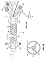
FIG. 1A is a side elevation view of an ablation catheter for treatment of venous reflux disease; -
FIG. 1B is a cross-sectional side view of the catheter ofFIG. 1A , taken along the plane designated 1B-1B inFIG. 1A ; and -
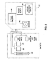
FIG. 2 is a block diagram of an ablation system utilizing the catheter ofFIG. 1A . - Referring to
FIGS. 1A and 1B , anablation catheter 10 includes acatheter body 12, which is preferably an extrusion formed of a flexible polymeric material suitable for surgical use.Body 12 preferably includes threefluid lumens lumens catheter body 12. Acentral guidewire lumen 19 extends from the proximal end to the distal end of the catheter and receives aguidewire 21. - A pair of spaced-
apart balloons 20 is disposed on thecatheter body 12. The balloons are formed of an elastic or inelastic material. Each balloon is fluidly coupled tolumen 14 viasmall inflation openings 22 formed in thebody 12. The proximal end of thelumen 14 terminates at aninflation port 24 that couples to a source of inflation medium for inflation and deflation of theballoons 20. The balloons are preferably sealed against thecatheter body 12 such that when they are inflated they do not leak inflation medium directly into the vein.Lumen 14 itself is collapsible when a vacuum is applied to it. - An
electrode array 26 is positioned on thecatheter body 12 between theballoons 20. Thearray 26 includes one or morebipolar electrode pairs 28 preferably formed over the circumference of the catheter body. In a preferred configuration, the array extends along a sufficient length of catheter to permit simultaneous ablation of the full length of the targeted region of the vein. This avoids the need for repositioning the catheter within the vein, or for dragging the energized electrode through the vein to ablate the desired length of the vessel. - The electrodes preferably are constructed of a thin layer deposit using a conductive metal, for instance silver or gold. In another preferred embodiment the electrodes are constructed of a fine elastic conductive mesh with integrated insulating and conducting regions. An electrode mesh of this type is utilized on the NovaSure® Endometrial Ablation System sold by Novacept, Inc. of Palo Alto, CA.
- Insulated electrode leads (not shown) extend from the electrode pairs and through the
catheter body 12, and are coupled to acable 42 that interfaces with a RF controller 44 (FIG. 2 ). Preferably, theRF controller 44 includesRF circuitry 45 having both low and high impedance transformation circuits, and automatically selects the impedance circuit based on real time measured impedance of the ablation electrode in contact with the vessel tissue. An impedance-matched RF generator system of this type is described in international Publication Nr.WO 99/58070, Filed May 7, 1999 - The center-to-center spacing C between the electrodes (i.e. the distance between the centers of adjacent electrodes), the distance between the electrodes, and the widths of the electrodes are selected so that ablation will reach predetermined depths within the tissue, particularly when controlled power is delivered through the electrodes (where power density is the power delivered per unit surface area at which low impedance, low voltage ablation can be achieved).
- The depth of ablation is also affected by the electrode density (i.e., the percentage of the target tissue area which is in contact with active electrode surfaces) and may be regulated by pre-selecting the amount of this active electrode coverage. For example, the depth of ablation is much greater when the active electrode surface covers more than 10% of the target tissue than it is when the active electrode surfaces covers 1% of the target tissue.
- Although the electrodes shown in the drawings are arranged in a particular pattern, it should be appreciated that the electrodes may be arranged in any pattern that will result in ablation to desired depths.
- In one embodiment, the electrode spacing is approximately 0.5 - 1.0 mm with the active electrode surfaces covering approximately 10% of the target region. Delivery of approximately 8-10 watts of power per centimeter squared of tissue surface area using this electrode configuration will achieve ablation to a depth of approximately 0.1-2.5 mm. After reaching this ablation depth, the impedance of the tissue will become so great that ablation will self-terminate as described with respect to the operation of the system.
- The proximal end of
lumen 18 bifurcates into two sections oftubing First section 34 terminates at avacuum relief valve 38 that regulates the vacuum level within the catheter.Second section 36 terminates at aflush port 40 that is connectable to a source of saline or other fluid that may be injected into the vein viaperforations 30.Flush port 40 may also be coupled to avacuum monitoring circuit 48, which detects the pressure within thelumen vacuum pump 46 andvacuum monitoring circuit 48 may be housed within theRF controller 44, as shown inFIG. 2 . - A plurality of pores/
perforations 30 is formed in thecatheter body 12, betweenballoons 20 as shown. If the array is formed of a mesh, the perforations may be the interstices of the mesh. The perforations are fluidly coupled tofluid lumens 16, 18 - which may be contiguous with one other at the distal portion of the catheter body. The proximal end oflumen 16 terminates at asuction port 32 that is connectable to avacuum pump 46. Thus, application of a vacuum to lumen 16 draws moisture and fluid through theperforations 30, throughlumen 16 of thecatheter body 12 and out the proximal end of the catheter body. The vacuum signal is transmitted uplumen 18, throughconnection 40, to the pressure transducer in thevacuum monitoring circuit 48 in the RF Controller. The vacuum monitoring circuit assures the target tissue is under the appropriate vacuum limits at appropriate times throughout the procedure. Application of a vacuum also facilitates electrode-tissue contact by drawing tissue into contact with the electrodes. - One preferred method of using the
ablation catheter 10 will next be described. First, an incision is made to expose the vessel to be treated. For the saphenous vein or long saphenous vein, the incision is formed in the patient's groin.Guidewire 21 is inserted into the vein and the catheter is advanced over theguidewire 21 into the desired position within the vein.Balloons port 24 andlumen 14. A flushing medium, preferably saline, is directed intoflush port 40 and exits the catheter viaperforations 30 where it functions to flush the region of the vessel between the balloons. It may be desirable to initiate this flow of saline prior to, or simultaneously with, insertion of the catheter to prevent blood from clogging pores/perforations 30. Suction is applied viavacuum port 32 to aspirate the mixture of saline and blood from the vein, throughperforations 30 and out of the catheter. The suction in this step is preferably insufficient to collapse the vein. Flushing and aspiration are continued until much of the blood is removed from the vein, although some blood may remain in the vein without impairing operation of the catheter. A slight positive pressure, sufficient to overcome venous pressure, is maintained on the system after the flushing process is complete in order to maintain patency inperforations 30 andlumens - Next, the
RF controller 44 energizes theelectrode array 26 to deliver ablation energy to the surrounding tissue. Suction is preferably applied to thevacuum port 32 during ablation for two reasons. First, suction collapses the vessel, thus drawing the interior wall of the vessel into contact with the electrode array. Second, suction draws moisture (gas and vapor) away from the ablation site. Moisture build-up at the ablation site may be detrimental in that it provides a conductive layer that carries current from the electrodes even when ablation has reached the desired depth. This undesirable continued current flow heats the moisture and surrounding tissue, and thus causes ablation to continue by unpredictable thermal conduction means. - Ablation causes tissue to dehydrate and thus to decrease in conductivity. By applying a vacuum or otherwise shunting moisture away from the ablation site, and thus preventing liquid build-up, there is no liquid conductor at the ablation area during use of the ablation device of the present invention. Thus, when ablation has reached the desired depth, the impedance at the tissue surface becomes sufficiently high to stop or nearly stop the flow of current into the tissue. RF ablation thereby stops and thermal ablation does not occur in significant amounts. If the RF controller is equipped with an impedance monitor, a physician utilizing the ablation device can monitor the impedance at the electrodes and will know that ablation has self-terminated once the impedance rises to a certain level. Alternatively the impedance monitor may automatically shut down power delivery after the desired impedance has been reached, and display a message or signal a type of indicator to notify the physician that the procedure is complete. By contrast, in the absence of moisture removal, the presence of liquid around the bipolar electrodes would cause the impedance monitor to give a low impedance reading regardless of the depth of ablation which had already been carried out, since current would continue to travel through the low-impedance liquid layer.
- Collagen and elastin in the vessel wall may shrink during power application, collapsing the vessel down onto the catheter. Once ablation has self-tenninated and/or ablation has been performed to the desired depth, delivery of RF energy to the electrodes is terminated. Relieving the pressure at
connector 24 deflates balloons 20. Applying a vacuum toconnector 24 then collapseslumen 14, reducing the size of the catheter to facilitate removal. The catheter is then removed from the vein. A compression bandage is applied to patient over the site of the ablation, so as to hold opposing portions of the ablated vessel in contact with one another. This causes the ablated portions of the vessel to seal against one another, thus closing the vessel and causing blood flow be diverted to surround vessels.
Claims (7)
- A device for sealing a blood vessel, comprising:a catheter (10) having an elongate body (12) positionable within a blood vessel;a pair of inflatable balloon members (20) on the elongate body (12), the balloon members (20) expandable into contact with an interior wall of the blood vessel;a bipolar electrode array (26) on the elongate body (12) between the balloon members (20);at least one opening (30) in the elongate body (12), between the balloon members (20);a source of flushing fluid (40) coupled to the opening (30);a vacuum source (32, 46) fluidly coupled to the opening (30), the vacuum source (32, 46) providing sufficient vacuum pressure to aspirate blood and flushing fluid out of the blood vessel through the opening (30); anda source of ablation energy electrically coupled to the electrode array (26) such that energization of the electrode array (26) causes ablation of blood vessel tissue in contact with the electrode array (26).
- A device according to claim 1 wherein the vacuum source (32, 46) is further operable to draw the interior wall of the blood vessel into contact with the electrode array (26).
- A device according to claim 1 or 2 wherein the vacuum source (32, 46) is further operable to draw moisture generated during ablation away from the tissue and into the elongate body (12).
- A device according to claim 1, 2 or 3 wherein the at least one opening (30) comprises a plurality of openings in the elongate body (12).
- A device according to any of claims 1 to 4 wherein the source of ablation energy includes an RF generator (44) having a low impedance transformation circuit and a high impedance transformation circuit, an impedance detection circuit for measuring impedance of tissue in contact with the electrode array, and a control circuit for automatically selecting between the low impedance transformation circuit and the high impedance transformation circuit based on the impedance of the tissue in contact with the electrode array (26).
- A device according to claim 5 wherein the control circuit is for selecting the transformation circuit having an impedance closest to the measured impedance of the tissue in contact with the electrode array (28).
- A device according to any preceding claim wherein the elongate body is selectively collapsible to a reduced diameter configuration to facilitate removal of the catheter from a blood vessel.
Applications Claiming Priority (3)
| Application Number | Priority Date | Filing Date | Title |
|---|---|---|---|
| US26132101P | 2001-01-16 | 2001-01-16 | |
| PCT/US2002/001171 WO2002056772A2 (en) | 2001-01-16 | 2002-01-16 | Apparatus and method for treating venous reflux |
| US261321P | 2009-11-14 |
Publications (2)
| Publication Number | Publication Date |
|---|---|
| EP1357842A2 EP1357842A2 (en) | 2003-11-05 |
| EP1357842B1 true EP1357842B1 (en) | 2010-11-03 |
Family
ID=22992785
Family Applications (1)
| Application Number | Title | Priority Date | Filing Date |
|---|---|---|---|
| EP02705802A Expired - Lifetime EP1357842B1 (en) | 2001-01-16 | 2002-01-16 | Apparatus and method for treating venous reflux |
Country Status (7)
| Country | Link |
|---|---|
| US (3) | US6712815B2 (en) |
| EP (1) | EP1357842B1 (en) |
| JP (1) | JP4281992B2 (en) |
| AT (1) | ATE486525T1 (en) |
| AU (1) | AU2002239929A1 (en) |
| DE (1) | DE60238178D1 (en) |
| WO (1) | WO2002056772A2 (en) |
Cited By (1)
| Publication number | Priority date | Publication date | Assignee | Title |
|---|---|---|---|---|
| DE102013107437A1 (en) * | 2013-07-12 | 2015-01-15 | Aesculap Ag | Apparatus and method for radiofrequency surgical removal of a tissue section |
Families Citing this family (195)
| Publication number | Priority date | Publication date | Assignee | Title |
|---|---|---|---|---|
| US7604633B2 (en) | 1996-04-12 | 2009-10-20 | Cytyc Corporation | Moisture transport system for contact electrocoagulation |
| US6464697B1 (en) * | 1998-02-19 | 2002-10-15 | Curon Medical, Inc. | Stomach and adjoining tissue regions in the esophagus |
| US8551082B2 (en) | 1998-05-08 | 2013-10-08 | Cytyc Surgical Products | Radio-frequency generator for powering an ablation device |
| US20040215235A1 (en) * | 1999-11-16 | 2004-10-28 | Barrx, Inc. | Methods and systems for determining physiologic characteristics for treatment of the esophagus |
| WO2001035846A1 (en) * | 1999-11-16 | 2001-05-25 | Ganz Robert A | System and method of treating abnormal tissue in the human esophagus |
| US20060095032A1 (en) | 1999-11-16 | 2006-05-04 | Jerome Jackson | Methods and systems for determining physiologic characteristics for treatment of the esophagus |
| DE60238178D1 (en) | 2001-01-16 | 2010-12-16 | Cytyc Surgical Products Palo A | DEVICE AND METHOD FOR TREATING THE VENOUS REFLUX |
| US7033336B2 (en) * | 2002-03-29 | 2006-04-25 | Gore Enterprise Holdings, Inc. | Proximal catheter assembly having a relief valve |
| US8347891B2 (en) | 2002-04-08 | 2013-01-08 | Medtronic Ardian Luxembourg S.A.R.L. | Methods and apparatus for performing a non-continuous circumferential treatment of a body lumen |
| US7756583B2 (en) | 2002-04-08 | 2010-07-13 | Ardian, Inc. | Methods and apparatus for intravascularly-induced neuromodulation |
| US20080287939A1 (en) * | 2002-07-10 | 2008-11-20 | Appling William M | Endovascular thermal treatment device with flexible guide tip and method |
| IES20080278A2 (en) * | 2003-01-31 | 2008-06-11 | Preton Ltd | A process for producing a performance enhanced single-layer blow-moulded container |
| US7223266B2 (en) * | 2003-02-04 | 2007-05-29 | Cardiodex Ltd. | Methods and apparatus for hemostasis following arterial catheterization |
| US7115127B2 (en) * | 2003-02-04 | 2006-10-03 | Cardiodex, Ltd. | Methods and apparatus for hemostasis following arterial catheterization |
| DE202004021942U1 (en) | 2003-09-12 | 2013-05-13 | Vessix Vascular, Inc. | Selectable eccentric remodeling and / or ablation of atherosclerotic material |
| US7150745B2 (en) | 2004-01-09 | 2006-12-19 | Barrx Medical, Inc. | Devices and methods for treatment of luminal tissue |
| CA2553940A1 (en) * | 2004-01-30 | 2005-08-18 | Nmt Medical, Inc. | Devices, systems, and methods for closure of cardiac openings |
| US7824408B2 (en) | 2004-08-05 | 2010-11-02 | Tyco Healthcare Group, Lp | Methods and apparatus for coagulating and/or constricting hollow anatomical structures |
| US20080027425A1 (en) * | 2004-09-01 | 2008-01-31 | Kazumasa Orihashi | Varicosis Treatment Apparatus |
| US9713730B2 (en) | 2004-09-10 | 2017-07-25 | Boston Scientific Scimed, Inc. | Apparatus and method for treatment of in-stent restenosis |
| US8396548B2 (en) | 2008-11-14 | 2013-03-12 | Vessix Vascular, Inc. | Selective drug delivery in a lumen |
| US9125667B2 (en) | 2004-09-10 | 2015-09-08 | Vessix Vascular, Inc. | System for inducing desirable temperature effects on body tissue |
| JP5068662B2 (en) | 2004-11-22 | 2012-11-07 | カーディオデックス リミテッド | Heat treatment technology for varicose veins |
| US7731712B2 (en) | 2004-12-20 | 2010-06-08 | Cytyc Corporation | Method and system for transcervical tubal occlusion |
| US7918795B2 (en) * | 2005-02-02 | 2011-04-05 | Gynesonics, Inc. | Method and device for uterine fibroid treatment |
| US20060289602A1 (en) * | 2005-06-23 | 2006-12-28 | Ethicon Endo-Surgery, Inc. | Surgical instrument with articulating shaft with double pivot closure and single pivot frame ground |
| US7780054B2 (en) * | 2005-02-18 | 2010-08-24 | Ethicon Endo-Surgery, Inc. | Surgical instrument with laterally moved shaft actuator coupled to pivoting articulation joint |
| US7559450B2 (en) * | 2005-02-18 | 2009-07-14 | Ethicon Endo-Surgery, Inc. | Surgical instrument incorporating a fluid transfer controlled articulation mechanism |
| US7654431B2 (en) * | 2005-02-18 | 2010-02-02 | Ethicon Endo-Surgery, Inc. | Surgical instrument with guided laterally moving articulation member |
| US7784662B2 (en) | 2005-02-18 | 2010-08-31 | Ethicon Endo-Surgery, Inc. | Surgical instrument with articulating shaft with single pivot closure and double pivot frame ground |
| US7559452B2 (en) * | 2005-02-18 | 2009-07-14 | Ethicon Endo-Surgery, Inc. | Surgical instrument having fluid actuated opposing jaws |
| US7625372B2 (en) | 2005-02-23 | 2009-12-01 | Vnus Medical Technologies, Inc. | Methods and apparatus for coagulating and/or constricting hollow anatomical structures |
| CN100352523C (en) * | 2005-02-24 | 2007-12-05 | 四川大学华西医院 | Multi saccule catheter in blood vessel |
| US7674260B2 (en) | 2005-04-28 | 2010-03-09 | Cytyc Corporation | Emergency hemostasis device utilizing energy |
| DE202006021213U1 (en) | 2005-07-21 | 2013-11-08 | Covidien Lp | Apparatus for treating a hollow anatomical structure |
| US20070027468A1 (en) * | 2005-08-01 | 2007-02-01 | Wales Kenneth S | Surgical instrument with an articulating shaft locking mechanism |
| US9259267B2 (en) | 2005-09-06 | 2016-02-16 | W.L. Gore & Associates, Inc. | Devices and methods for treating cardiac tissue |
| US7797056B2 (en) | 2005-09-06 | 2010-09-14 | Nmt Medical, Inc. | Removable intracardiac RF device |
| US8702694B2 (en) | 2005-11-23 | 2014-04-22 | Covidien Lp | Auto-aligning ablating device and method of use |
| US7959627B2 (en) | 2005-11-23 | 2011-06-14 | Barrx Medical, Inc. | Precision ablating device |
| US7997278B2 (en) | 2005-11-23 | 2011-08-16 | Barrx Medical, Inc. | Precision ablating method |
| US7874986B2 (en) * | 2006-04-20 | 2011-01-25 | Gynesonics, Inc. | Methods and devices for visualization and ablation of tissue |
| US10058342B2 (en) | 2006-01-12 | 2018-08-28 | Gynesonics, Inc. | Devices and methods for treatment of tissue |
| US20070161905A1 (en) * | 2006-01-12 | 2007-07-12 | Gynesonics, Inc. | Intrauterine ultrasound and method for use |
| US9357977B2 (en) * | 2006-01-12 | 2016-06-07 | Gynesonics, Inc. | Interventional deployment and imaging system |
| US7815571B2 (en) * | 2006-04-20 | 2010-10-19 | Gynesonics, Inc. | Rigid delivery systems having inclined ultrasound and needle |
| US11259825B2 (en) | 2006-01-12 | 2022-03-01 | Gynesonics, Inc. | Devices and methods for treatment of tissue |
| US20070173798A1 (en) * | 2006-01-23 | 2007-07-26 | Adams Mark L | Minimally invasive methods for thermal treatment |
| US20080045880A1 (en) * | 2006-02-11 | 2008-02-21 | Rune Kjeken | Device and method for single-needle in vivo electroporation |
| US20080287857A1 (en) * | 2006-02-11 | 2008-11-20 | Rune Kjeken | Device and method for single-needle in vivo electroporation |
| CA3063263C (en) * | 2006-02-11 | 2024-01-16 | Genetronics, Inc. | Device and method for single-needle in vivo electroporation |
| US10595819B2 (en) | 2006-04-20 | 2020-03-24 | Gynesonics, Inc. | Ablation device with articulated imaging transducer |
| US20100056926A1 (en) * | 2008-08-26 | 2010-03-04 | Gynesonics, Inc. | Ablation device with articulated imaging transducer |
| US8206300B2 (en) | 2008-08-26 | 2012-06-26 | Gynesonics, Inc. | Ablation device with articulated imaging transducer |
| US8019435B2 (en) | 2006-05-02 | 2011-09-13 | Boston Scientific Scimed, Inc. | Control of arterial smooth muscle tone |
| RU2008151150A (en) * | 2006-05-24 | 2010-06-27 | Эмсижен Лимитед (Gb) | DEVICE FOR SEALING VESSELS AND METHODS OF SEALING |
| US8486060B2 (en) * | 2006-09-18 | 2013-07-16 | Cytyc Corporation | Power ramping during RF ablation |
| US20080071269A1 (en) * | 2006-09-18 | 2008-03-20 | Cytyc Corporation | Curved Endoscopic Medical Device |
| AU2007310988B2 (en) | 2006-10-18 | 2013-08-15 | Vessix Vascular, Inc. | Tuned RF energy and electrical tissue characterization for selective treatment of target tissues |
| AU2007310986B2 (en) | 2006-10-18 | 2013-07-04 | Boston Scientific Scimed, Inc. | Inducing desirable temperature effects on body tissue |
| JP2008132163A (en) * | 2006-11-28 | 2008-06-12 | Olympus Medical Systems Corp | Tool for treatment of body lumen occlusion |
| US7846160B2 (en) | 2006-12-21 | 2010-12-07 | Cytyc Corporation | Method and apparatus for sterilization |
| WO2008137757A1 (en) | 2007-05-04 | 2008-11-13 | Barrx Medical, Inc. | Method and apparatus for gastrointestinal tract ablation for treatment of obesity |
| US8784338B2 (en) | 2007-06-22 | 2014-07-22 | Covidien Lp | Electrical means to normalize ablational energy transmission to a luminal tissue surface of varying size |
| WO2009009443A1 (en) | 2007-07-06 | 2009-01-15 | Barrx Medical, Inc. | Method and apparatus for gastrointestinal tract ablation to achieve loss of persistent and/or recurrent excess body weight following a weight-loss operation |
| US20090012518A1 (en) * | 2007-07-06 | 2009-01-08 | Utley David S | Method and Apparatus for Ablation of Benign, Pre-Cancerous and Early Cancerous Lesions That Originate Within the Epithelium and are Limited to the Mucosal Layer of the Gastrointestinal Tract |
| KR101513926B1 (en) * | 2007-07-06 | 2015-04-21 | 코비디엔 엘피 | Ablation in the gastrointestinal tract to achieve hemostasis and eradicate lesions with a propensity for bleeding |
| US8646460B2 (en) | 2007-07-30 | 2014-02-11 | Covidien Lp | Cleaning device and methods |
| US8273012B2 (en) | 2007-07-30 | 2012-09-25 | Tyco Healthcare Group, Lp | Cleaning device and methods |
| US8366706B2 (en) | 2007-08-15 | 2013-02-05 | Cardiodex, Ltd. | Systems and methods for puncture closure |
| US8088072B2 (en) | 2007-10-12 | 2012-01-03 | Gynesonics, Inc. | Methods and systems for controlled deployment of needles in tissue |
| US9474571B2 (en) * | 2007-10-15 | 2016-10-25 | Boston Scientific Scimed, Inc. | Percutaneous tissue ablation probe with occlusive bodies |
| US20090287081A1 (en) * | 2008-04-29 | 2009-11-19 | Gynesonics , Inc | Submucosal fibroid ablation for the treatment of menorrhagia |
| JP2011522633A (en) * | 2008-06-06 | 2011-08-04 | バリックス・メディカル・コーポレイション | Vascular treatment device and method |
| DE102008045038A1 (en) * | 2008-08-29 | 2010-03-04 | Osypka, Peter, Dr.- Ing. | Device for ablating the mouth of the pulmonary veins |
| US10695126B2 (en) | 2008-10-06 | 2020-06-30 | Santa Anna Tech Llc | Catheter with a double balloon structure to generate and apply a heated ablative zone to tissue |
| US10064697B2 (en) | 2008-10-06 | 2018-09-04 | Santa Anna Tech Llc | Vapor based ablation system for treating various indications |
| US8821486B2 (en) | 2009-11-13 | 2014-09-02 | Hermes Innovations, LLC | Tissue ablation systems and methods |
| US8540708B2 (en) | 2008-10-21 | 2013-09-24 | Hermes Innovations Llc | Endometrial ablation method |
| US8500732B2 (en) | 2008-10-21 | 2013-08-06 | Hermes Innovations Llc | Endometrial ablation devices and systems |
| US8197477B2 (en) | 2008-10-21 | 2012-06-12 | Hermes Innovations Llc | Tissue ablation methods |
| US9662163B2 (en) | 2008-10-21 | 2017-05-30 | Hermes Innovations Llc | Endometrial ablation devices and systems |
| US8197476B2 (en) | 2008-10-21 | 2012-06-12 | Hermes Innovations Llc | Tissue ablation systems |
| US8372068B2 (en) | 2008-10-21 | 2013-02-12 | Hermes Innovations, LLC | Tissue ablation systems |
| AU2009314133B2 (en) | 2008-11-17 | 2015-12-10 | Vessix Vascular, Inc. | Selective accumulation of energy with or without knowledge of tissue topography |
| EP2355733A4 (en) * | 2008-11-18 | 2012-11-14 | Veniti Inc | Hot tip vein therapy device |
| US8475450B2 (en) | 2008-12-30 | 2013-07-02 | Biosense Webster, Inc. | Dual-purpose lasso catheter with irrigation |
| US8600472B2 (en) * | 2008-12-30 | 2013-12-03 | Biosense Webster (Israel), Ltd. | Dual-purpose lasso catheter with irrigation using circumferentially arranged ring bump electrodes |
| US20100191265A1 (en) * | 2009-01-29 | 2010-07-29 | Cavu Medical, Inc. | Assembly and method for automatically controlling pressure for a gastric band |
| US20100198209A1 (en) * | 2009-01-30 | 2010-08-05 | Tartaglia Joseph M | Hemorrhoid Therapy and Method |
| US8262574B2 (en) | 2009-02-27 | 2012-09-11 | Gynesonics, Inc. | Needle and tine deployment mechanism |
| WO2010104720A1 (en) * | 2009-03-09 | 2010-09-16 | Cytyc Corporation | Ablation device with suction capability |
| US8343078B2 (en) * | 2009-11-11 | 2013-01-01 | Minerva Surgical, Inc. | Methods for evaluating the integrity of a uterine cavity |
| US8715278B2 (en) | 2009-11-11 | 2014-05-06 | Minerva Surgical, Inc. | System for endometrial ablation utilizing radio frequency |
| US9289257B2 (en) | 2009-11-13 | 2016-03-22 | Minerva Surgical, Inc. | Methods and systems for endometrial ablation utilizing radio frequency |
| US8529562B2 (en) | 2009-11-13 | 2013-09-10 | Minerva Surgical, Inc | Systems and methods for endometrial ablation |
| US11896282B2 (en) | 2009-11-13 | 2024-02-13 | Hermes Innovations Llc | Tissue ablation systems and method |
| US8920415B2 (en) * | 2009-12-16 | 2014-12-30 | Biosense Webster (Israel) Ltd. | Catheter with helical electrode |
| US8608735B2 (en) * | 2009-12-30 | 2013-12-17 | Biosense Webster (Israel) Ltd. | Catheter with arcuate end section |
| US9616246B2 (en) | 2010-01-04 | 2017-04-11 | Covidien Lp | Apparatus and methods for treating hollow anatomical structures |
| US9421059B2 (en) | 2010-04-27 | 2016-08-23 | Minerva Surgical, Inc. | Device for endometrial ablation having an expandable seal for a cervical canal |
| KR20130108067A (en) | 2010-04-09 | 2013-10-02 | 베식스 바스큘라 인코포레이티드 | Power generating and control apparatus for the treatment of tissue |
| US9192790B2 (en) | 2010-04-14 | 2015-11-24 | Boston Scientific Scimed, Inc. | Focused ultrasonic renal denervation |
| US20110270239A1 (en) * | 2010-04-29 | 2011-11-03 | Werneth Randell L | Transseptal crossing device |
| US8473067B2 (en) | 2010-06-11 | 2013-06-25 | Boston Scientific Scimed, Inc. | Renal denervation and stimulation employing wireless vascular energy transfer arrangement |
| US8956348B2 (en) | 2010-07-21 | 2015-02-17 | Minerva Surgical, Inc. | Methods and systems for endometrial ablation |
| US9463062B2 (en) | 2010-07-30 | 2016-10-11 | Boston Scientific Scimed, Inc. | Cooled conductive balloon RF catheter for renal nerve ablation |
| US9155589B2 (en) | 2010-07-30 | 2015-10-13 | Boston Scientific Scimed, Inc. | Sequential activation RF electrode set for renal nerve ablation |
| US9358365B2 (en) | 2010-07-30 | 2016-06-07 | Boston Scientific Scimed, Inc. | Precision electrode movement control for renal nerve ablation |
| US9084609B2 (en) | 2010-07-30 | 2015-07-21 | Boston Scientific Scime, Inc. | Spiral balloon catheter for renal nerve ablation |
| US9408661B2 (en) | 2010-07-30 | 2016-08-09 | Patrick A. Haverkost | RF electrodes on multiple flexible wires for renal nerve ablation |
| US8974451B2 (en) | 2010-10-25 | 2015-03-10 | Boston Scientific Scimed, Inc. | Renal nerve ablation using conductive fluid jet and RF energy |
| US9220558B2 (en) | 2010-10-27 | 2015-12-29 | Boston Scientific Scimed, Inc. | RF renal denervation catheter with multiple independent electrodes |
| US9510897B2 (en) | 2010-11-05 | 2016-12-06 | Hermes Innovations Llc | RF-electrode surface and method of fabrication |
| US9028485B2 (en) | 2010-11-15 | 2015-05-12 | Boston Scientific Scimed, Inc. | Self-expanding cooling electrode for renal nerve ablation |
| US9089350B2 (en) * | 2010-11-16 | 2015-07-28 | Boston Scientific Scimed, Inc. | Renal denervation catheter with RF electrode and integral contrast dye injection arrangement |
| US9668811B2 (en) | 2010-11-16 | 2017-06-06 | Boston Scientific Scimed, Inc. | Minimally invasive access for renal nerve ablation |
| US9326751B2 (en) | 2010-11-17 | 2016-05-03 | Boston Scientific Scimed, Inc. | Catheter guidance of external energy for renal denervation |
| US9060761B2 (en) | 2010-11-18 | 2015-06-23 | Boston Scientific Scime, Inc. | Catheter-focused magnetic field induced renal nerve ablation |
| US9023034B2 (en) | 2010-11-22 | 2015-05-05 | Boston Scientific Scimed, Inc. | Renal ablation electrode with force-activatable conduction apparatus |
| US9192435B2 (en) | 2010-11-22 | 2015-11-24 | Boston Scientific Scimed, Inc. | Renal denervation catheter with cooled RF electrode |
| US20130030410A1 (en) * | 2010-11-23 | 2013-01-31 | William Joseph Drasler | Venous heated ablation catheter |
| WO2012071058A1 (en) * | 2010-11-23 | 2012-05-31 | William Joseph Drasler | Venous heated ablation catheter |
| US20120157993A1 (en) | 2010-12-15 | 2012-06-21 | Jenson Mark L | Bipolar Off-Wall Electrode Device for Renal Nerve Ablation |
| WO2012100095A1 (en) | 2011-01-19 | 2012-07-26 | Boston Scientific Scimed, Inc. | Guide-compatible large-electrode catheter for renal nerve ablation with reduced arterial injury |
| US10278774B2 (en) | 2011-03-18 | 2019-05-07 | Covidien Lp | Selectively expandable operative element support structure and methods of use |
| CA2832311A1 (en) | 2011-04-08 | 2012-11-29 | Covidien Lp | Iontophoresis drug delivery system and method for denervation of the renal sympathetic nerve and iontophoretic drug delivery |
| EP2701623B1 (en) | 2011-04-25 | 2016-08-17 | Medtronic Ardian Luxembourg S.à.r.l. | Apparatus related to constrained deployment of cryogenic balloons for limited cryogenic ablation of vessel walls |
| US9220433B2 (en) | 2011-06-30 | 2015-12-29 | Biosense Webster (Israel), Ltd. | Catheter with variable arcuate distal section |
| CN103813745B (en) | 2011-07-20 | 2016-06-29 | 波士顿科学西美德公司 | In order to visualize, be directed at and to melt transcutaneous device and the method for nerve |
| JP6106669B2 (en) | 2011-07-22 | 2017-04-05 | ボストン サイエンティフィック サイムド,インコーポレイテッドBoston Scientific Scimed,Inc. | A neuromodulation system having a neuromodulation element that can be placed in a helical guide |
| US9662169B2 (en) | 2011-07-30 | 2017-05-30 | Biosense Webster (Israel) Ltd. | Catheter with flow balancing valve |
| WO2013055826A1 (en) | 2011-10-10 | 2013-04-18 | Boston Scientific Scimed, Inc. | Medical devices including ablation electrodes |
| US9420955B2 (en) | 2011-10-11 | 2016-08-23 | Boston Scientific Scimed, Inc. | Intravascular temperature monitoring system and method |
| US10085799B2 (en) | 2011-10-11 | 2018-10-02 | Boston Scientific Scimed, Inc. | Off-wall electrode device and methods for nerve modulation |
| US9364284B2 (en) | 2011-10-12 | 2016-06-14 | Boston Scientific Scimed, Inc. | Method of making an off-wall spacer cage |
| WO2013058962A1 (en) | 2011-10-18 | 2013-04-25 | Boston Scientific Scimed, Inc. | Deflectable medical devices |
| EP2768568B1 (en) | 2011-10-18 | 2020-05-06 | Boston Scientific Scimed, Inc. | Integrated crossing balloon catheter |
| EP2775948B1 (en) | 2011-11-08 | 2018-04-04 | Boston Scientific Scimed, Inc. | Ostial renal nerve ablation |
| US9119600B2 (en) | 2011-11-15 | 2015-09-01 | Boston Scientific Scimed, Inc. | Device and methods for renal nerve modulation monitoring |
| US9119632B2 (en) | 2011-11-21 | 2015-09-01 | Boston Scientific Scimed, Inc. | Deflectable renal nerve ablation catheter |
| US9265969B2 (en) | 2011-12-21 | 2016-02-23 | Cardiac Pacemakers, Inc. | Methods for modulating cell function |
| WO2013096916A2 (en) | 2011-12-23 | 2013-06-27 | Vessix Vascular, Inc. | Methods and apparatuses for remodeling tissue of or adjacent to a body passage |
| US9433760B2 (en) | 2011-12-28 | 2016-09-06 | Boston Scientific Scimed, Inc. | Device and methods for nerve modulation using a novel ablation catheter with polymeric ablative elements |
| US9050106B2 (en) | 2011-12-29 | 2015-06-09 | Boston Scientific Scimed, Inc. | Off-wall electrode device and methods for nerve modulation |
| US10660703B2 (en) | 2012-05-08 | 2020-05-26 | Boston Scientific Scimed, Inc. | Renal nerve modulation devices |
| US9192426B2 (en) | 2012-06-26 | 2015-11-24 | Covidien Lp | Ablation device having an expandable chamber for anchoring the ablation device to tissue |
| US10321946B2 (en) | 2012-08-24 | 2019-06-18 | Boston Scientific Scimed, Inc. | Renal nerve modulation devices with weeping RF ablation balloons |
| US9173696B2 (en) | 2012-09-17 | 2015-11-03 | Boston Scientific Scimed, Inc. | Self-positioning electrode system and method for renal nerve modulation |
| US10549127B2 (en) | 2012-09-21 | 2020-02-04 | Boston Scientific Scimed, Inc. | Self-cooling ultrasound ablation catheter |
| US10398464B2 (en) | 2012-09-21 | 2019-09-03 | Boston Scientific Scimed, Inc. | System for nerve modulation and innocuous thermal gradient nerve block |
| CN104869930B (en) | 2012-10-10 | 2020-12-25 | 波士顿科学国际有限公司 | Renal neuromodulation apparatus and methods |
| EP2945556A4 (en) | 2013-01-17 | 2016-08-31 | Virender K Sharma | Method and apparatus for tissue ablation |
| US9956033B2 (en) | 2013-03-11 | 2018-05-01 | Boston Scientific Scimed, Inc. | Medical devices for modulating nerves |
| US9693821B2 (en) | 2013-03-11 | 2017-07-04 | Boston Scientific Scimed, Inc. | Medical devices for modulating nerves |
| US9808311B2 (en) | 2013-03-13 | 2017-11-07 | Boston Scientific Scimed, Inc. | Deflectable medical devices |
| US9297845B2 (en) | 2013-03-15 | 2016-03-29 | Boston Scientific Scimed, Inc. | Medical devices and methods for treatment of hypertension that utilize impedance compensation |
| US10265122B2 (en) | 2013-03-15 | 2019-04-23 | Boston Scientific Scimed, Inc. | Nerve ablation devices and related methods of use |
| EP2967734B1 (en) | 2013-03-15 | 2019-05-15 | Boston Scientific Scimed, Inc. | Methods and apparatuses for remodeling tissue of or adjacent to a body passage |
| US9901394B2 (en) | 2013-04-04 | 2018-02-27 | Hermes Innovations Llc | Medical ablation system and method of making |
| EP3010437A1 (en) | 2013-06-21 | 2016-04-27 | Boston Scientific Scimed, Inc. | Renal denervation balloon catheter with ride along electrode support |
| CN105473092B (en) | 2013-06-21 | 2019-05-17 | 波士顿科学国际有限公司 | The medical instrument for renal nerve ablation with rotatable shaft |
| US9707036B2 (en) | 2013-06-25 | 2017-07-18 | Boston Scientific Scimed, Inc. | Devices and methods for nerve modulation using localized indifferent electrodes |
| WO2015002787A1 (en) | 2013-07-01 | 2015-01-08 | Boston Scientific Scimed, Inc. | Medical devices for renal nerve ablation |
| EP3019106A1 (en) | 2013-07-11 | 2016-05-18 | Boston Scientific Scimed, Inc. | Medical device with stretchable electrode assemblies |
| WO2015006480A1 (en) | 2013-07-11 | 2015-01-15 | Boston Scientific Scimed, Inc. | Devices and methods for nerve modulation |
| WO2015010074A1 (en) | 2013-07-19 | 2015-01-22 | Boston Scientific Scimed, Inc. | Spiral bipolar electrode renal denervation balloon |
| US10695124B2 (en) | 2013-07-22 | 2020-06-30 | Boston Scientific Scimed, Inc. | Renal nerve ablation catheter having twist balloon |
| WO2015013205A1 (en) | 2013-07-22 | 2015-01-29 | Boston Scientific Scimed, Inc. | Medical devices for renal nerve ablation |
| WO2015027096A1 (en) | 2013-08-22 | 2015-02-26 | Boston Scientific Scimed, Inc. | Flexible circuit having improved adhesion to a renal nerve modulation balloon |
| EP3041425B1 (en) | 2013-09-04 | 2022-04-13 | Boston Scientific Scimed, Inc. | Radio frequency (rf) balloon catheter having flushing and cooling capability |
| WO2015038947A1 (en) | 2013-09-13 | 2015-03-19 | Boston Scientific Scimed, Inc. | Ablation balloon with vapor deposited cover layer |
| US11246654B2 (en) | 2013-10-14 | 2022-02-15 | Boston Scientific Scimed, Inc. | Flexible renal nerve ablation devices and related methods of use and manufacture |
| CN105592778B (en) | 2013-10-14 | 2019-07-23 | 波士顿科学医学有限公司 | High-resolution cardiac mapping electrod-array conduit |
| US9770606B2 (en) | 2013-10-15 | 2017-09-26 | Boston Scientific Scimed, Inc. | Ultrasound ablation catheter with cooling infusion and centering basket |
| AU2014334574B2 (en) | 2013-10-15 | 2017-07-06 | Boston Scientific Scimed, Inc. | Medical device balloon |
| US9649125B2 (en) | 2013-10-15 | 2017-05-16 | Hermes Innovations Llc | Laparoscopic device |
| CN105636538B (en) | 2013-10-18 | 2019-01-15 | 波士顿科学国际有限公司 | Foley's tube with flexible wire and its correlation technique for using and manufacturing |
| CN105658163B (en) | 2013-10-25 | 2020-08-18 | 波士顿科学国际有限公司 | Embedded thermocouple in denervation flexible circuit |
| WO2015103617A1 (en) | 2014-01-06 | 2015-07-09 | Boston Scientific Scimed, Inc. | Tear resistant flex circuit assembly |
| US11000679B2 (en) | 2014-02-04 | 2021-05-11 | Boston Scientific Scimed, Inc. | Balloon protection and rewrapping devices and related methods of use |
| JP6325121B2 (en) | 2014-02-04 | 2018-05-16 | ボストン サイエンティフィック サイムド,インコーポレイテッドBoston Scientific Scimed,Inc. | Alternative placement of temperature sensors on bipolar electrodes |
| US10709490B2 (en) | 2014-05-07 | 2020-07-14 | Medtronic Ardian Luxembourg S.A.R.L. | Catheter assemblies comprising a direct heating element for renal neuromodulation and associated systems and methods |
| CN105705192A (en) * | 2014-07-22 | 2016-06-22 | 潘湘斌 | New type of balloon catheter used for ultrasound-guided percutaneous pulmonary valve balloon angioplasty |
| US10492856B2 (en) | 2015-01-26 | 2019-12-03 | Hermes Innovations Llc | Surgical fluid management system and method of use |
| EP3288477A4 (en) | 2015-04-29 | 2018-12-19 | Cirrus Technologies Ltd. | Medical ablation device and method of use |
| WO2017035028A1 (en) * | 2015-08-24 | 2017-03-02 | Sierra Medical International, Inc. | Apparatus and method for treating a blood vessel |
| US20190008585A1 (en) * | 2015-10-22 | 2019-01-10 | Shanghai Golden Leaf Med Tec Co., Ltd. | Radio frequency ablation device comprising balloon blocking catheter and ablation method therefor |
| US10052149B2 (en) | 2016-01-20 | 2018-08-21 | RELIGN Corporation | Arthroscopic devices and methods |
| JP2019514481A (en) | 2016-04-22 | 2019-06-06 | リライン コーポレーション | Arthroscopic device and method |
| WO2018005382A1 (en) | 2016-07-01 | 2018-01-04 | Aaron Germain | Arthroscopic devices and methods |
| AU2017359338B2 (en) | 2016-11-11 | 2022-09-08 | Gynesonics, Inc. | Controlled treatment of tissue and dynamic interaction with, and comparison of, tissue and/or treatment data |
| EP3781011A4 (en) * | 2018-04-17 | 2022-01-12 | The Board of Trustees of the Leland Stanford Junior University | Airway visualization system |
| CA3102080A1 (en) | 2018-06-01 | 2019-12-05 | Santa Anna Tech Llc | Multi-stage vapor-based ablation treatment methods and vapor generation and delivery systems |
| US11554214B2 (en) | 2019-06-26 | 2023-01-17 | Meditrina, Inc. | Fluid management system |
Family Cites Families (34)
| Publication number | Priority date | Publication date | Assignee | Title |
|---|---|---|---|---|
| US628393A (en) * | 1898-10-13 | 1899-07-04 | John L Hall | Electric railway-gate. |
| US4601713A (en) * | 1985-06-11 | 1986-07-22 | Genus Catheter Technologies, Inc. | Variable diameter catheter |
| US5078717A (en) | 1989-04-13 | 1992-01-07 | Everest Medical Corporation | Ablation catheter with selectively deployable electrodes |
| DE3915636C1 (en) | 1989-05-12 | 1990-04-26 | Sass, Wolfgang, Dr. | |
| US5318532A (en) * | 1989-10-03 | 1994-06-07 | C. R. Bard, Inc. | Multilumen catheter with variable cross-section lumens |
| DE4001086A1 (en) | 1990-01-17 | 1991-07-18 | Weikl Andreas | Medical treatment catheter widening constricted vessels - has two expandable balloons spaced in axial direction with heat conductive piece between them |
| US5405322A (en) * | 1993-08-12 | 1995-04-11 | Boston Scientific Corporation | Method for treating aneurysms with a thermal source |
| US5505700A (en) | 1994-06-14 | 1996-04-09 | Cordis Corporation | Electro-osmotic infusion catheter |
| US5609598A (en) | 1994-12-30 | 1997-03-11 | Vnus Medical Technologies, Inc. | Method and apparatus for minimally invasive treatment of chronic venous insufficiency |
| US5834024A (en) * | 1995-01-05 | 1998-11-10 | Fh Faulding & Co. Limited | Controlled absorption diltiazem pharmaceutical formulation |
| CA2215049A1 (en) | 1995-03-14 | 1996-09-19 | Michael D. Laufer | Venous pump efficiency test system and method |
| US6152899A (en) | 1996-03-05 | 2000-11-28 | Vnus Medical Technologies, Inc. | Expandable catheter having improved electrode design, and method for applying energy |
| US6036687A (en) | 1996-03-05 | 2000-03-14 | Vnus Medical Technologies, Inc. | Method and apparatus for treating venous insufficiency |
| US6139527A (en) | 1996-03-05 | 2000-10-31 | Vnus Medical Technologies, Inc. | Method and apparatus for treating hemorrhoids |
| US6033397A (en) | 1996-03-05 | 2000-03-07 | Vnus Medical Technologies, Inc. | Method and apparatus for treating esophageal varices |
| US6813520B2 (en) * | 1996-04-12 | 2004-11-02 | Novacept | Method for ablating and/or coagulating tissue using moisture transport |
| US5769880A (en) * | 1996-04-12 | 1998-06-23 | Novacept | Moisture transport system for contact electrocoagulation |
| US6077257A (en) | 1996-05-06 | 2000-06-20 | Vidacare, Inc. | Ablation of rectal and other internal body structures |
| US6231507B1 (en) | 1997-06-02 | 2001-05-15 | Vnus Medical Technologies, Inc. | Pressure tourniquet with ultrasound window and method of use |
| US5938660A (en) * | 1997-06-27 | 1999-08-17 | Daig Corporation | Process and device for the treatment of atrial arrhythmia |
| US6117101A (en) | 1997-07-08 | 2000-09-12 | The Regents Of The University Of California | Circumferential ablation device assembly |
| US6401719B1 (en) * | 1997-09-11 | 2002-06-11 | Vnus Medical Technologies, Inc. | Method of ligating hollow anatomical structures |
| US6179832B1 (en) | 1997-09-11 | 2001-01-30 | Vnus Medical Technologies, Inc. | Expandable catheter having two sets of electrodes |
| US6200312B1 (en) | 1997-09-11 | 2001-03-13 | Vnus Medical Technologies, Inc. | Expandable vein ligator catheter having multiple electrode leads |
| US6258084B1 (en) | 1997-09-11 | 2001-07-10 | Vnus Medical Technologies, Inc. | Method for applying energy to biological tissue including the use of tumescent tissue compression |
| US6014589A (en) | 1997-11-12 | 2000-01-11 | Vnus Medical Technologies, Inc. | Catheter having expandable electrodes and adjustable stent |
| US6508815B1 (en) * | 1998-05-08 | 2003-01-21 | Novacept | Radio-frequency generator for powering an ablation device |
| US6322559B1 (en) | 1998-07-06 | 2001-11-27 | Vnus Medical Technologies, Inc. | Electrode catheter having coil structure |
| US6238393B1 (en) * | 1998-07-07 | 2001-05-29 | Medtronic, Inc. | Method and apparatus for creating a bi-polar virtual electrode used for the ablation of tissue |
| US6712812B2 (en) * | 1999-08-05 | 2004-03-30 | Broncus Technologies, Inc. | Devices for creating collateral channels |
| US6485500B1 (en) * | 2000-03-21 | 2002-11-26 | Advanced Cardiovascular Systems, Inc. | Emboli protection system |
| US6336687B1 (en) * | 2000-03-21 | 2002-01-08 | Hr Textron, Inc. | Anti-lock brake system three way direct drive valve |
| WO2001097897A1 (en) * | 2000-06-20 | 2001-12-27 | Starion Instruments, Inc. | Devices and methods for repair of valves in the human body |
| DE60238178D1 (en) * | 2001-01-16 | 2010-12-16 | Cytyc Surgical Products Palo A | DEVICE AND METHOD FOR TREATING THE VENOUS REFLUX |
-
2002
- 2002-01-16 DE DE60238178T patent/DE60238178D1/en not_active Expired - Lifetime
- 2002-01-16 WO PCT/US2002/001171 patent/WO2002056772A2/en active Application Filing
- 2002-01-16 AU AU2002239929A patent/AU2002239929A1/en not_active Abandoned
- 2002-01-16 US US10/052,157 patent/US6712815B2/en not_active Expired - Fee Related
- 2002-01-16 EP EP02705802A patent/EP1357842B1/en not_active Expired - Lifetime
- 2002-01-16 JP JP2002557285A patent/JP4281992B2/en not_active Expired - Fee Related
- 2002-01-16 AT AT02705802T patent/ATE486525T1/en not_active IP Right Cessation
-
2003
- 2003-10-01 US US10/676,619 patent/US7087052B2/en not_active Expired - Fee Related
-
2004
- 2004-01-05 US US10/751,592 patent/US7294126B2/en not_active Expired - Fee Related
Cited By (1)
| Publication number | Priority date | Publication date | Assignee | Title |
|---|---|---|---|---|
| DE102013107437A1 (en) * | 2013-07-12 | 2015-01-15 | Aesculap Ag | Apparatus and method for radiofrequency surgical removal of a tissue section |
Also Published As
| Publication number | Publication date |
|---|---|
| US7294126B2 (en) | 2007-11-13 |
| ATE486525T1 (en) | 2010-11-15 |
| JP2004522501A (en) | 2004-07-29 |
| US20040143251A1 (en) | 2004-07-22 |
| EP1357842A2 (en) | 2003-11-05 |
| US20040064135A1 (en) | 2004-04-01 |
| US20020143325A1 (en) | 2002-10-03 |
| DE60238178D1 (en) | 2010-12-16 |
| US6712815B2 (en) | 2004-03-30 |
| US7087052B2 (en) | 2006-08-08 |
| WO2002056772A3 (en) | 2002-10-24 |
| JP4281992B2 (en) | 2009-06-17 |
| AU2002239929A1 (en) | 2002-07-30 |
| WO2002056772A2 (en) | 2002-07-25 |
Similar Documents
| Publication | Publication Date | Title |
|---|---|---|
| EP1357842B1 (en) | Apparatus and method for treating venous reflux | |
| US8267931B2 (en) | Method of ligating hollow anatomical structures | |
| US6401719B1 (en) | Method of ligating hollow anatomical structures | |
| AU770951B2 (en) | Electrocatheter for inducing vessel stenosys having two arrays of diverging electrodes | |
| US7184827B1 (en) | Shrinkage of dilatations in the body | |
| EP0608609B1 (en) | Catheter for RF ablation with cooled electrode | |
| US20010041888A1 (en) | Method and apparatus for applying energy to biological tissue including the use of tumescent tissue compression | |
| EP3030183A1 (en) | Electrosurgical device and method | |
| US20140088584A1 (en) | Medical device balloon catheter | |
| CN219742868U (en) | Ablation catheter and myocardial ablation system with same |
Legal Events
| Date | Code | Title | Description |
|---|---|---|---|
| PUAI | Public reference made under article 153(3) epc to a published international application that has entered the european phase |
Free format text: ORIGINAL CODE: 0009012 |
|
| 17P | Request for examination filed |
Effective date: 20030806 |
|
| AK | Designated contracting states |
Kind code of ref document: A2 Designated state(s): AT BE CH CY DE DK ES FI FR GB GR IE IT LI LU MC NL PT SE TR |
|
| AX | Request for extension of the european patent |
Extension state: AL LT LV MK RO SI |
|
| 17Q | First examination report despatched |
Effective date: 20090220 |
|
| RAP1 | Party data changed (applicant data changed or rights of an application transferred) |
Owner name: CYTYC SURGICAL PRODUCTS |
|
| GRAP | Despatch of communication of intention to grant a patent |
Free format text: ORIGINAL CODE: EPIDOSNIGR1 |
|
| RIN1 | Information on inventor provided before grant (corrected) |
Inventor name: SAMPSON, RUSSEL MAHLON Inventor name: SKALNYI, EUGENE Inventor name: HILARIO, ESTALA |
|
| GRAS | Grant fee paid |
Free format text: ORIGINAL CODE: EPIDOSNIGR3 |
|
| GRAA | (expected) grant |
Free format text: ORIGINAL CODE: 0009210 |
|
| AK | Designated contracting states |
Kind code of ref document: B1 Designated state(s): AT BE CH CY DE DK ES FI FR GB GR IE IT LI LU MC NL PT SE TR |
|
| REG | Reference to a national code |
Ref country code: GB Ref legal event code: FG4D |
|
| REG | Reference to a national code |
Ref country code: CH Ref legal event code: EP |
|
| REG | Reference to a national code |
Ref country code: IE Ref legal event code: FG4D |
|
| REF | Corresponds to: |
Ref document number: 60238178 Country of ref document: DE Date of ref document: 20101216 Kind code of ref document: P |
|
| REG | Reference to a national code |
Ref country code: NL Ref legal event code: VDEP Effective date: 20101103 |
|
| PG25 | Lapsed in a contracting state [announced via postgrant information from national office to epo] |
Ref country code: PT Free format text: LAPSE BECAUSE OF FAILURE TO SUBMIT A TRANSLATION OF THE DESCRIPTION OR TO PAY THE FEE WITHIN THE PRESCRIBED TIME-LIMIT Effective date: 20110303 Ref country code: NL Free format text: LAPSE BECAUSE OF FAILURE TO SUBMIT A TRANSLATION OF THE DESCRIPTION OR TO PAY THE FEE WITHIN THE PRESCRIBED TIME-LIMIT Effective date: 20101103 Ref country code: FI Free format text: LAPSE BECAUSE OF FAILURE TO SUBMIT A TRANSLATION OF THE DESCRIPTION OR TO PAY THE FEE WITHIN THE PRESCRIBED TIME-LIMIT Effective date: 20101103 Ref country code: AT Free format text: LAPSE BECAUSE OF FAILURE TO SUBMIT A TRANSLATION OF THE DESCRIPTION OR TO PAY THE FEE WITHIN THE PRESCRIBED TIME-LIMIT Effective date: 20101103 Ref country code: SE Free format text: LAPSE BECAUSE OF FAILURE TO SUBMIT A TRANSLATION OF THE DESCRIPTION OR TO PAY THE FEE WITHIN THE PRESCRIBED TIME-LIMIT Effective date: 20101103 |
|
| PGFP | Annual fee paid to national office [announced via postgrant information from national office to epo] |
Ref country code: FR Payment date: 20110301 Year of fee payment: 10 Ref country code: DE Payment date: 20110127 Year of fee payment: 10 |
|
| PG25 | Lapsed in a contracting state [announced via postgrant information from national office to epo] |
Ref country code: GR Free format text: LAPSE BECAUSE OF FAILURE TO SUBMIT A TRANSLATION OF THE DESCRIPTION OR TO PAY THE FEE WITHIN THE PRESCRIBED TIME-LIMIT Effective date: 20110204 |
|
| PG25 | Lapsed in a contracting state [announced via postgrant information from national office to epo] |
Ref country code: BE Free format text: LAPSE BECAUSE OF FAILURE TO SUBMIT A TRANSLATION OF THE DESCRIPTION OR TO PAY THE FEE WITHIN THE PRESCRIBED TIME-LIMIT Effective date: 20101103 Ref country code: ES Free format text: LAPSE BECAUSE OF FAILURE TO SUBMIT A TRANSLATION OF THE DESCRIPTION OR TO PAY THE FEE WITHIN THE PRESCRIBED TIME-LIMIT Effective date: 20110214 |
|
| PGFP | Annual fee paid to national office [announced via postgrant information from national office to epo] |
Ref country code: GB Payment date: 20110125 Year of fee payment: 10 |
|
| PG25 | Lapsed in a contracting state [announced via postgrant information from national office to epo] |
Ref country code: DK Free format text: LAPSE BECAUSE OF FAILURE TO SUBMIT A TRANSLATION OF THE DESCRIPTION OR TO PAY THE FEE WITHIN THE PRESCRIBED TIME-LIMIT Effective date: 20101103 Ref country code: MC Free format text: LAPSE BECAUSE OF NON-PAYMENT OF DUE FEES Effective date: 20110131 |
|
| REG | Reference to a national code |
Ref country code: CH Ref legal event code: PL |
|
| PLBE | No opposition filed within time limit |
Free format text: ORIGINAL CODE: 0009261 |
|
| STAA | Information on the status of an ep patent application or granted ep patent |
Free format text: STATUS: NO OPPOSITION FILED WITHIN TIME LIMIT |
|
| 26N | No opposition filed |
Effective date: 20110804 |
|
| REG | Reference to a national code |
Ref country code: IE Ref legal event code: MM4A |
|
| PG25 | Lapsed in a contracting state [announced via postgrant information from national office to epo] |
Ref country code: LI Free format text: LAPSE BECAUSE OF NON-PAYMENT OF DUE FEES Effective date: 20110131 Ref country code: CH Free format text: LAPSE BECAUSE OF NON-PAYMENT OF DUE FEES Effective date: 20110131 |
|
| REG | Reference to a national code |
Ref country code: DE Ref legal event code: R097 Ref document number: 60238178 Country of ref document: DE Effective date: 20110804 |
|
| PG25 | Lapsed in a contracting state [announced via postgrant information from national office to epo] |
Ref country code: IT Free format text: LAPSE BECAUSE OF FAILURE TO SUBMIT A TRANSLATION OF THE DESCRIPTION OR TO PAY THE FEE WITHIN THE PRESCRIBED TIME-LIMIT Effective date: 20101103 |
|
| PG25 | Lapsed in a contracting state [announced via postgrant information from national office to epo] |
Ref country code: IE Free format text: LAPSE BECAUSE OF NON-PAYMENT OF DUE FEES Effective date: 20110116 |
|
| GBPC | Gb: european patent ceased through non-payment of renewal fee |
Effective date: 20120116 |
|
| REG | Reference to a national code |
Ref country code: FR Ref legal event code: ST Effective date: 20120928 |
|
| PG25 | Lapsed in a contracting state [announced via postgrant information from national office to epo] |
Ref country code: GB Free format text: LAPSE BECAUSE OF NON-PAYMENT OF DUE FEES Effective date: 20120116 Ref country code: DE Free format text: LAPSE BECAUSE OF NON-PAYMENT OF DUE FEES Effective date: 20120801 |
|
| REG | Reference to a national code |
Ref country code: DE Ref legal event code: R119 Ref document number: 60238178 Country of ref document: DE Effective date: 20120801 |
|
| PG25 | Lapsed in a contracting state [announced via postgrant information from national office to epo] |
Ref country code: FR Free format text: LAPSE BECAUSE OF NON-PAYMENT OF DUE FEES Effective date: 20120131 |
|
| PG25 | Lapsed in a contracting state [announced via postgrant information from national office to epo] |
Ref country code: LU Free format text: LAPSE BECAUSE OF NON-PAYMENT OF DUE FEES Effective date: 20110116 Ref country code: CY Free format text: LAPSE BECAUSE OF FAILURE TO SUBMIT A TRANSLATION OF THE DESCRIPTION OR TO PAY THE FEE WITHIN THE PRESCRIBED TIME-LIMIT Effective date: 20101103 |
|
| PG25 | Lapsed in a contracting state [announced via postgrant information from national office to epo] |
Ref country code: TR Free format text: LAPSE BECAUSE OF FAILURE TO SUBMIT A TRANSLATION OF THE DESCRIPTION OR TO PAY THE FEE WITHIN THE PRESCRIBED TIME-LIMIT Effective date: 20101103 |