EP1356972A1 - Method/system for controlling a hybrid vehicle drivetrain - Google Patents
Method/system for controlling a hybrid vehicle drivetrain Download PDFInfo
- Publication number
- EP1356972A1 EP1356972A1 EP02445044A EP02445044A EP1356972A1 EP 1356972 A1 EP1356972 A1 EP 1356972A1 EP 02445044 A EP02445044 A EP 02445044A EP 02445044 A EP02445044 A EP 02445044A EP 1356972 A1 EP1356972 A1 EP 1356972A1
- Authority
- EP
- European Patent Office
- Prior art keywords
- drivetrain
- torque
- gear shift
- transmission
- electric machine
- Prior art date
- Legal status (The legal status is an assumption and is not a legal conclusion. Google has not performed a legal analysis and makes no representation as to the accuracy of the status listed.)
- Granted
Links
Images


Classifications
-
- B—PERFORMING OPERATIONS; TRANSPORTING
- B60—VEHICLES IN GENERAL
- B60L—PROPULSION OF ELECTRICALLY-PROPELLED VEHICLES; SUPPLYING ELECTRIC POWER FOR AUXILIARY EQUIPMENT OF ELECTRICALLY-PROPELLED VEHICLES; ELECTRODYNAMIC BRAKE SYSTEMS FOR VEHICLES IN GENERAL; MAGNETIC SUSPENSION OR LEVITATION FOR VEHICLES; MONITORING OPERATING VARIABLES OF ELECTRICALLY-PROPELLED VEHICLES; ELECTRIC SAFETY DEVICES FOR ELECTRICALLY-PROPELLED VEHICLES
- B60L58/00—Methods or circuit arrangements for monitoring or controlling batteries or fuel cells, specially adapted for electric vehicles
- B60L58/10—Methods or circuit arrangements for monitoring or controlling batteries or fuel cells, specially adapted for electric vehicles for monitoring or controlling batteries
-
- B—PERFORMING OPERATIONS; TRANSPORTING
- B60—VEHICLES IN GENERAL
- B60K—ARRANGEMENT OR MOUNTING OF PROPULSION UNITS OR OF TRANSMISSIONS IN VEHICLES; ARRANGEMENT OR MOUNTING OF PLURAL DIVERSE PRIME-MOVERS IN VEHICLES; AUXILIARY DRIVES FOR VEHICLES; INSTRUMENTATION OR DASHBOARDS FOR VEHICLES; ARRANGEMENTS IN CONNECTION WITH COOLING, AIR INTAKE, GAS EXHAUST OR FUEL SUPPLY OF PROPULSION UNITS IN VEHICLES
- B60K6/00—Arrangement or mounting of plural diverse prime-movers for mutual or common propulsion, e.g. hybrid propulsion systems comprising electric motors and internal combustion engines ; Control systems therefor, i.e. systems controlling two or more prime movers, or controlling one of these prime movers and any of the transmission, drive or drive units Informative references: mechanical gearings with secondary electric drive F16H3/72; arrangements for handling mechanical energy structurally associated with the dynamo-electric machine H02K7/00; machines comprising structurally interrelated motor and generator parts H02K51/00; dynamo-electric machines not otherwise provided for in H02K see H02K99/00
- B60K6/20—Arrangement or mounting of plural diverse prime-movers for mutual or common propulsion, e.g. hybrid propulsion systems comprising electric motors and internal combustion engines ; Control systems therefor, i.e. systems controlling two or more prime movers, or controlling one of these prime movers and any of the transmission, drive or drive units Informative references: mechanical gearings with secondary electric drive F16H3/72; arrangements for handling mechanical energy structurally associated with the dynamo-electric machine H02K7/00; machines comprising structurally interrelated motor and generator parts H02K51/00; dynamo-electric machines not otherwise provided for in H02K see H02K99/00 the prime-movers consisting of electric motors and internal combustion engines, e.g. HEVs
- B60K6/42—Arrangement or mounting of plural diverse prime-movers for mutual or common propulsion, e.g. hybrid propulsion systems comprising electric motors and internal combustion engines ; Control systems therefor, i.e. systems controlling two or more prime movers, or controlling one of these prime movers and any of the transmission, drive or drive units Informative references: mechanical gearings with secondary electric drive F16H3/72; arrangements for handling mechanical energy structurally associated with the dynamo-electric machine H02K7/00; machines comprising structurally interrelated motor and generator parts H02K51/00; dynamo-electric machines not otherwise provided for in H02K see H02K99/00 the prime-movers consisting of electric motors and internal combustion engines, e.g. HEVs characterised by the architecture of the hybrid electric vehicle
- B60K6/48—Parallel type
-
- B—PERFORMING OPERATIONS; TRANSPORTING
- B60—VEHICLES IN GENERAL
- B60K—ARRANGEMENT OR MOUNTING OF PROPULSION UNITS OR OF TRANSMISSIONS IN VEHICLES; ARRANGEMENT OR MOUNTING OF PLURAL DIVERSE PRIME-MOVERS IN VEHICLES; AUXILIARY DRIVES FOR VEHICLES; INSTRUMENTATION OR DASHBOARDS FOR VEHICLES; ARRANGEMENTS IN CONNECTION WITH COOLING, AIR INTAKE, GAS EXHAUST OR FUEL SUPPLY OF PROPULSION UNITS IN VEHICLES
- B60K6/00—Arrangement or mounting of plural diverse prime-movers for mutual or common propulsion, e.g. hybrid propulsion systems comprising electric motors and internal combustion engines ; Control systems therefor, i.e. systems controlling two or more prime movers, or controlling one of these prime movers and any of the transmission, drive or drive units Informative references: mechanical gearings with secondary electric drive F16H3/72; arrangements for handling mechanical energy structurally associated with the dynamo-electric machine H02K7/00; machines comprising structurally interrelated motor and generator parts H02K51/00; dynamo-electric machines not otherwise provided for in H02K see H02K99/00
- B60K6/20—Arrangement or mounting of plural diverse prime-movers for mutual or common propulsion, e.g. hybrid propulsion systems comprising electric motors and internal combustion engines ; Control systems therefor, i.e. systems controlling two or more prime movers, or controlling one of these prime movers and any of the transmission, drive or drive units Informative references: mechanical gearings with secondary electric drive F16H3/72; arrangements for handling mechanical energy structurally associated with the dynamo-electric machine H02K7/00; machines comprising structurally interrelated motor and generator parts H02K51/00; dynamo-electric machines not otherwise provided for in H02K see H02K99/00 the prime-movers consisting of electric motors and internal combustion engines, e.g. HEVs
- B60K6/50—Architecture of the driveline characterised by arrangement or kind of transmission units
- B60K6/54—Transmission for changing ratio
-
- B—PERFORMING OPERATIONS; TRANSPORTING
- B60—VEHICLES IN GENERAL
- B60L—PROPULSION OF ELECTRICALLY-PROPELLED VEHICLES; SUPPLYING ELECTRIC POWER FOR AUXILIARY EQUIPMENT OF ELECTRICALLY-PROPELLED VEHICLES; ELECTRODYNAMIC BRAKE SYSTEMS FOR VEHICLES IN GENERAL; MAGNETIC SUSPENSION OR LEVITATION FOR VEHICLES; MONITORING OPERATING VARIABLES OF ELECTRICALLY-PROPELLED VEHICLES; ELECTRIC SAFETY DEVICES FOR ELECTRICALLY-PROPELLED VEHICLES
- B60L15/00—Methods, circuits, or devices for controlling the traction-motor speed of electrically-propelled vehicles
- B60L15/20—Methods, circuits, or devices for controlling the traction-motor speed of electrically-propelled vehicles for control of the vehicle or its driving motor to achieve a desired performance, e.g. speed, torque, programmed variation of speed
-
- B—PERFORMING OPERATIONS; TRANSPORTING
- B60—VEHICLES IN GENERAL
- B60L—PROPULSION OF ELECTRICALLY-PROPELLED VEHICLES; SUPPLYING ELECTRIC POWER FOR AUXILIARY EQUIPMENT OF ELECTRICALLY-PROPELLED VEHICLES; ELECTRODYNAMIC BRAKE SYSTEMS FOR VEHICLES IN GENERAL; MAGNETIC SUSPENSION OR LEVITATION FOR VEHICLES; MONITORING OPERATING VARIABLES OF ELECTRICALLY-PROPELLED VEHICLES; ELECTRIC SAFETY DEVICES FOR ELECTRICALLY-PROPELLED VEHICLES
- B60L50/00—Electric propulsion with power supplied within the vehicle
- B60L50/10—Electric propulsion with power supplied within the vehicle using propulsion power supplied by engine-driven generators, e.g. generators driven by combustion engines
- B60L50/16—Electric propulsion with power supplied within the vehicle using propulsion power supplied by engine-driven generators, e.g. generators driven by combustion engines with provision for separate direct mechanical propulsion
-
- B—PERFORMING OPERATIONS; TRANSPORTING
- B60—VEHICLES IN GENERAL
- B60L—PROPULSION OF ELECTRICALLY-PROPELLED VEHICLES; SUPPLYING ELECTRIC POWER FOR AUXILIARY EQUIPMENT OF ELECTRICALLY-PROPELLED VEHICLES; ELECTRODYNAMIC BRAKE SYSTEMS FOR VEHICLES IN GENERAL; MAGNETIC SUSPENSION OR LEVITATION FOR VEHICLES; MONITORING OPERATING VARIABLES OF ELECTRICALLY-PROPELLED VEHICLES; ELECTRIC SAFETY DEVICES FOR ELECTRICALLY-PROPELLED VEHICLES
- B60L58/00—Methods or circuit arrangements for monitoring or controlling batteries or fuel cells, specially adapted for electric vehicles
- B60L58/10—Methods or circuit arrangements for monitoring or controlling batteries or fuel cells, specially adapted for electric vehicles for monitoring or controlling batteries
- B60L58/16—Methods or circuit arrangements for monitoring or controlling batteries or fuel cells, specially adapted for electric vehicles for monitoring or controlling batteries responding to battery ageing, e.g. to the number of charging cycles or the state of health [SoH]
-
- B—PERFORMING OPERATIONS; TRANSPORTING
- B60—VEHICLES IN GENERAL
- B60W—CONJOINT CONTROL OF VEHICLE SUB-UNITS OF DIFFERENT TYPE OR DIFFERENT FUNCTION; CONTROL SYSTEMS SPECIALLY ADAPTED FOR HYBRID VEHICLES; ROAD VEHICLE DRIVE CONTROL SYSTEMS FOR PURPOSES NOT RELATED TO THE CONTROL OF A PARTICULAR SUB-UNIT
- B60W10/00—Conjoint control of vehicle sub-units of different type or different function
- B60W10/04—Conjoint control of vehicle sub-units of different type or different function including control of propulsion units
- B60W10/06—Conjoint control of vehicle sub-units of different type or different function including control of propulsion units including control of combustion engines
-
- B—PERFORMING OPERATIONS; TRANSPORTING
- B60—VEHICLES IN GENERAL
- B60W—CONJOINT CONTROL OF VEHICLE SUB-UNITS OF DIFFERENT TYPE OR DIFFERENT FUNCTION; CONTROL SYSTEMS SPECIALLY ADAPTED FOR HYBRID VEHICLES; ROAD VEHICLE DRIVE CONTROL SYSTEMS FOR PURPOSES NOT RELATED TO THE CONTROL OF A PARTICULAR SUB-UNIT
- B60W10/00—Conjoint control of vehicle sub-units of different type or different function
- B60W10/04—Conjoint control of vehicle sub-units of different type or different function including control of propulsion units
- B60W10/08—Conjoint control of vehicle sub-units of different type or different function including control of propulsion units including control of electric propulsion units, e.g. motors or generators
-
- B—PERFORMING OPERATIONS; TRANSPORTING
- B60—VEHICLES IN GENERAL
- B60W—CONJOINT CONTROL OF VEHICLE SUB-UNITS OF DIFFERENT TYPE OR DIFFERENT FUNCTION; CONTROL SYSTEMS SPECIALLY ADAPTED FOR HYBRID VEHICLES; ROAD VEHICLE DRIVE CONTROL SYSTEMS FOR PURPOSES NOT RELATED TO THE CONTROL OF A PARTICULAR SUB-UNIT
- B60W10/00—Conjoint control of vehicle sub-units of different type or different function
- B60W10/10—Conjoint control of vehicle sub-units of different type or different function including control of change-speed gearings
-
- B—PERFORMING OPERATIONS; TRANSPORTING
- B60—VEHICLES IN GENERAL
- B60W—CONJOINT CONTROL OF VEHICLE SUB-UNITS OF DIFFERENT TYPE OR DIFFERENT FUNCTION; CONTROL SYSTEMS SPECIALLY ADAPTED FOR HYBRID VEHICLES; ROAD VEHICLE DRIVE CONTROL SYSTEMS FOR PURPOSES NOT RELATED TO THE CONTROL OF A PARTICULAR SUB-UNIT
- B60W20/00—Control systems specially adapted for hybrid vehicles
- B60W20/30—Control strategies involving selection of transmission gear ratio
-
- B—PERFORMING OPERATIONS; TRANSPORTING
- B60—VEHICLES IN GENERAL
- B60L—PROPULSION OF ELECTRICALLY-PROPELLED VEHICLES; SUPPLYING ELECTRIC POWER FOR AUXILIARY EQUIPMENT OF ELECTRICALLY-PROPELLED VEHICLES; ELECTRODYNAMIC BRAKE SYSTEMS FOR VEHICLES IN GENERAL; MAGNETIC SUSPENSION OR LEVITATION FOR VEHICLES; MONITORING OPERATING VARIABLES OF ELECTRICALLY-PROPELLED VEHICLES; ELECTRIC SAFETY DEVICES FOR ELECTRICALLY-PROPELLED VEHICLES
- B60L2240/00—Control parameters of input or output; Target parameters
- B60L2240/10—Vehicle control parameters
- B60L2240/12—Speed
-
- B—PERFORMING OPERATIONS; TRANSPORTING
- B60—VEHICLES IN GENERAL
- B60L—PROPULSION OF ELECTRICALLY-PROPELLED VEHICLES; SUPPLYING ELECTRIC POWER FOR AUXILIARY EQUIPMENT OF ELECTRICALLY-PROPELLED VEHICLES; ELECTRODYNAMIC BRAKE SYSTEMS FOR VEHICLES IN GENERAL; MAGNETIC SUSPENSION OR LEVITATION FOR VEHICLES; MONITORING OPERATING VARIABLES OF ELECTRICALLY-PROPELLED VEHICLES; ELECTRIC SAFETY DEVICES FOR ELECTRICALLY-PROPELLED VEHICLES
- B60L2240/00—Control parameters of input or output; Target parameters
- B60L2240/40—Drive Train control parameters
- B60L2240/42—Drive Train control parameters related to electric machines
- B60L2240/423—Torque
-
- B—PERFORMING OPERATIONS; TRANSPORTING
- B60—VEHICLES IN GENERAL
- B60L—PROPULSION OF ELECTRICALLY-PROPELLED VEHICLES; SUPPLYING ELECTRIC POWER FOR AUXILIARY EQUIPMENT OF ELECTRICALLY-PROPELLED VEHICLES; ELECTRODYNAMIC BRAKE SYSTEMS FOR VEHICLES IN GENERAL; MAGNETIC SUSPENSION OR LEVITATION FOR VEHICLES; MONITORING OPERATING VARIABLES OF ELECTRICALLY-PROPELLED VEHICLES; ELECTRIC SAFETY DEVICES FOR ELECTRICALLY-PROPELLED VEHICLES
- B60L2240/00—Control parameters of input or output; Target parameters
- B60L2240/40—Drive Train control parameters
- B60L2240/44—Drive Train control parameters related to combustion engines
- B60L2240/441—Speed
-
- B—PERFORMING OPERATIONS; TRANSPORTING
- B60—VEHICLES IN GENERAL
- B60L—PROPULSION OF ELECTRICALLY-PROPELLED VEHICLES; SUPPLYING ELECTRIC POWER FOR AUXILIARY EQUIPMENT OF ELECTRICALLY-PROPELLED VEHICLES; ELECTRODYNAMIC BRAKE SYSTEMS FOR VEHICLES IN GENERAL; MAGNETIC SUSPENSION OR LEVITATION FOR VEHICLES; MONITORING OPERATING VARIABLES OF ELECTRICALLY-PROPELLED VEHICLES; ELECTRIC SAFETY DEVICES FOR ELECTRICALLY-PROPELLED VEHICLES
- B60L2240/00—Control parameters of input or output; Target parameters
- B60L2240/40—Drive Train control parameters
- B60L2240/44—Drive Train control parameters related to combustion engines
- B60L2240/443—Torque
-
- B—PERFORMING OPERATIONS; TRANSPORTING
- B60—VEHICLES IN GENERAL
- B60L—PROPULSION OF ELECTRICALLY-PROPELLED VEHICLES; SUPPLYING ELECTRIC POWER FOR AUXILIARY EQUIPMENT OF ELECTRICALLY-PROPELLED VEHICLES; ELECTRODYNAMIC BRAKE SYSTEMS FOR VEHICLES IN GENERAL; MAGNETIC SUSPENSION OR LEVITATION FOR VEHICLES; MONITORING OPERATING VARIABLES OF ELECTRICALLY-PROPELLED VEHICLES; ELECTRIC SAFETY DEVICES FOR ELECTRICALLY-PROPELLED VEHICLES
- B60L2240/00—Control parameters of input or output; Target parameters
- B60L2240/40—Drive Train control parameters
- B60L2240/44—Drive Train control parameters related to combustion engines
- B60L2240/445—Temperature
-
- B—PERFORMING OPERATIONS; TRANSPORTING
- B60—VEHICLES IN GENERAL
- B60L—PROPULSION OF ELECTRICALLY-PROPELLED VEHICLES; SUPPLYING ELECTRIC POWER FOR AUXILIARY EQUIPMENT OF ELECTRICALLY-PROPELLED VEHICLES; ELECTRODYNAMIC BRAKE SYSTEMS FOR VEHICLES IN GENERAL; MAGNETIC SUSPENSION OR LEVITATION FOR VEHICLES; MONITORING OPERATING VARIABLES OF ELECTRICALLY-PROPELLED VEHICLES; ELECTRIC SAFETY DEVICES FOR ELECTRICALLY-PROPELLED VEHICLES
- B60L2240/00—Control parameters of input or output; Target parameters
- B60L2240/40—Drive Train control parameters
- B60L2240/48—Drive Train control parameters related to transmissions
- B60L2240/486—Operating parameters
-
- B—PERFORMING OPERATIONS; TRANSPORTING
- B60—VEHICLES IN GENERAL
- B60L—PROPULSION OF ELECTRICALLY-PROPELLED VEHICLES; SUPPLYING ELECTRIC POWER FOR AUXILIARY EQUIPMENT OF ELECTRICALLY-PROPELLED VEHICLES; ELECTRODYNAMIC BRAKE SYSTEMS FOR VEHICLES IN GENERAL; MAGNETIC SUSPENSION OR LEVITATION FOR VEHICLES; MONITORING OPERATING VARIABLES OF ELECTRICALLY-PROPELLED VEHICLES; ELECTRIC SAFETY DEVICES FOR ELECTRICALLY-PROPELLED VEHICLES
- B60L2240/00—Control parameters of input or output; Target parameters
- B60L2240/40—Drive Train control parameters
- B60L2240/54—Drive Train control parameters related to batteries
- B60L2240/545—Temperature
-
- B—PERFORMING OPERATIONS; TRANSPORTING
- B60—VEHICLES IN GENERAL
- B60L—PROPULSION OF ELECTRICALLY-PROPELLED VEHICLES; SUPPLYING ELECTRIC POWER FOR AUXILIARY EQUIPMENT OF ELECTRICALLY-PROPELLED VEHICLES; ELECTRODYNAMIC BRAKE SYSTEMS FOR VEHICLES IN GENERAL; MAGNETIC SUSPENSION OR LEVITATION FOR VEHICLES; MONITORING OPERATING VARIABLES OF ELECTRICALLY-PROPELLED VEHICLES; ELECTRIC SAFETY DEVICES FOR ELECTRICALLY-PROPELLED VEHICLES
- B60L2240/00—Control parameters of input or output; Target parameters
- B60L2240/40—Drive Train control parameters
- B60L2240/54—Drive Train control parameters related to batteries
- B60L2240/547—Voltage
-
- B—PERFORMING OPERATIONS; TRANSPORTING
- B60—VEHICLES IN GENERAL
- B60L—PROPULSION OF ELECTRICALLY-PROPELLED VEHICLES; SUPPLYING ELECTRIC POWER FOR AUXILIARY EQUIPMENT OF ELECTRICALLY-PROPELLED VEHICLES; ELECTRODYNAMIC BRAKE SYSTEMS FOR VEHICLES IN GENERAL; MAGNETIC SUSPENSION OR LEVITATION FOR VEHICLES; MONITORING OPERATING VARIABLES OF ELECTRICALLY-PROPELLED VEHICLES; ELECTRIC SAFETY DEVICES FOR ELECTRICALLY-PROPELLED VEHICLES
- B60L2240/00—Control parameters of input or output; Target parameters
- B60L2240/40—Drive Train control parameters
- B60L2240/54—Drive Train control parameters related to batteries
- B60L2240/549—Current
-
- B—PERFORMING OPERATIONS; TRANSPORTING
- B60—VEHICLES IN GENERAL
- B60L—PROPULSION OF ELECTRICALLY-PROPELLED VEHICLES; SUPPLYING ELECTRIC POWER FOR AUXILIARY EQUIPMENT OF ELECTRICALLY-PROPELLED VEHICLES; ELECTRODYNAMIC BRAKE SYSTEMS FOR VEHICLES IN GENERAL; MAGNETIC SUSPENSION OR LEVITATION FOR VEHICLES; MONITORING OPERATING VARIABLES OF ELECTRICALLY-PROPELLED VEHICLES; ELECTRIC SAFETY DEVICES FOR ELECTRICALLY-PROPELLED VEHICLES
- B60L2250/00—Driver interactions
- B60L2250/26—Driver interactions by pedal actuation
-
- B—PERFORMING OPERATIONS; TRANSPORTING
- B60—VEHICLES IN GENERAL
- B60W—CONJOINT CONTROL OF VEHICLE SUB-UNITS OF DIFFERENT TYPE OR DIFFERENT FUNCTION; CONTROL SYSTEMS SPECIALLY ADAPTED FOR HYBRID VEHICLES; ROAD VEHICLE DRIVE CONTROL SYSTEMS FOR PURPOSES NOT RELATED TO THE CONTROL OF A PARTICULAR SUB-UNIT
- B60W20/00—Control systems specially adapted for hybrid vehicles
-
- B—PERFORMING OPERATIONS; TRANSPORTING
- B60—VEHICLES IN GENERAL
- B60W—CONJOINT CONTROL OF VEHICLE SUB-UNITS OF DIFFERENT TYPE OR DIFFERENT FUNCTION; CONTROL SYSTEMS SPECIALLY ADAPTED FOR HYBRID VEHICLES; ROAD VEHICLE DRIVE CONTROL SYSTEMS FOR PURPOSES NOT RELATED TO THE CONTROL OF A PARTICULAR SUB-UNIT
- B60W2510/00—Input parameters relating to a particular sub-units
- B60W2510/08—Electric propulsion units
- B60W2510/083—Torque
-
- B—PERFORMING OPERATIONS; TRANSPORTING
- B60—VEHICLES IN GENERAL
- B60W—CONJOINT CONTROL OF VEHICLE SUB-UNITS OF DIFFERENT TYPE OR DIFFERENT FUNCTION; CONTROL SYSTEMS SPECIALLY ADAPTED FOR HYBRID VEHICLES; ROAD VEHICLE DRIVE CONTROL SYSTEMS FOR PURPOSES NOT RELATED TO THE CONTROL OF A PARTICULAR SUB-UNIT
- B60W2540/00—Input parameters relating to occupants
- B60W2540/10—Accelerator pedal position
-
- B—PERFORMING OPERATIONS; TRANSPORTING
- B60—VEHICLES IN GENERAL
- B60W—CONJOINT CONTROL OF VEHICLE SUB-UNITS OF DIFFERENT TYPE OR DIFFERENT FUNCTION; CONTROL SYSTEMS SPECIALLY ADAPTED FOR HYBRID VEHICLES; ROAD VEHICLE DRIVE CONTROL SYSTEMS FOR PURPOSES NOT RELATED TO THE CONTROL OF A PARTICULAR SUB-UNIT
- B60W2710/00—Output or target parameters relating to a particular sub-units
- B60W2710/10—Change speed gearings
- B60W2710/105—Output torque
-
- F—MECHANICAL ENGINEERING; LIGHTING; HEATING; WEAPONS; BLASTING
- F16—ENGINEERING ELEMENTS AND UNITS; GENERAL MEASURES FOR PRODUCING AND MAINTAINING EFFECTIVE FUNCTIONING OF MACHINES OR INSTALLATIONS; THERMAL INSULATION IN GENERAL
- F16H—GEARING
- F16H59/00—Control inputs to control units of change-speed-, or reversing-gearings for conveying rotary motion
- F16H59/14—Inputs being a function of torque or torque demand
- F16H59/18—Inputs being a function of torque or torque demand dependent on the position of the accelerator pedal
- F16H59/20—Kickdown
-
- F—MECHANICAL ENGINEERING; LIGHTING; HEATING; WEAPONS; BLASTING
- F16—ENGINEERING ELEMENTS AND UNITS; GENERAL MEASURES FOR PRODUCING AND MAINTAINING EFFECTIVE FUNCTIONING OF MACHINES OR INSTALLATIONS; THERMAL INSULATION IN GENERAL
- F16H—GEARING
- F16H61/00—Control functions within control units of change-speed- or reversing-gearings for conveying rotary motion ; Control of exclusively fluid gearing, friction gearing, gearings with endless flexible members or other particular types of gearing
- F16H61/02—Control functions within control units of change-speed- or reversing-gearings for conveying rotary motion ; Control of exclusively fluid gearing, friction gearing, gearings with endless flexible members or other particular types of gearing characterised by the signals used
- F16H61/0202—Control functions within control units of change-speed- or reversing-gearings for conveying rotary motion ; Control of exclusively fluid gearing, friction gearing, gearings with endless flexible members or other particular types of gearing characterised by the signals used the signals being electric
- F16H61/0204—Control functions within control units of change-speed- or reversing-gearings for conveying rotary motion ; Control of exclusively fluid gearing, friction gearing, gearings with endless flexible members or other particular types of gearing characterised by the signals used the signals being electric for gearshift control, e.g. control functions for performing shifting or generation of shift signal
- F16H61/0213—Control functions within control units of change-speed- or reversing-gearings for conveying rotary motion ; Control of exclusively fluid gearing, friction gearing, gearings with endless flexible members or other particular types of gearing characterised by the signals used the signals being electric for gearshift control, e.g. control functions for performing shifting or generation of shift signal characterised by the method for generating shift signals
-
- Y—GENERAL TAGGING OF NEW TECHNOLOGICAL DEVELOPMENTS; GENERAL TAGGING OF CROSS-SECTIONAL TECHNOLOGIES SPANNING OVER SEVERAL SECTIONS OF THE IPC; TECHNICAL SUBJECTS COVERED BY FORMER USPC CROSS-REFERENCE ART COLLECTIONS [XRACs] AND DIGESTS
- Y02—TECHNOLOGIES OR APPLICATIONS FOR MITIGATION OR ADAPTATION AGAINST CLIMATE CHANGE
- Y02T—CLIMATE CHANGE MITIGATION TECHNOLOGIES RELATED TO TRANSPORTATION
- Y02T10/00—Road transport of goods or passengers
- Y02T10/10—Internal combustion engine [ICE] based vehicles
- Y02T10/40—Engine management systems
-
- Y—GENERAL TAGGING OF NEW TECHNOLOGICAL DEVELOPMENTS; GENERAL TAGGING OF CROSS-SECTIONAL TECHNOLOGIES SPANNING OVER SEVERAL SECTIONS OF THE IPC; TECHNICAL SUBJECTS COVERED BY FORMER USPC CROSS-REFERENCE ART COLLECTIONS [XRACs] AND DIGESTS
- Y02—TECHNOLOGIES OR APPLICATIONS FOR MITIGATION OR ADAPTATION AGAINST CLIMATE CHANGE
- Y02T—CLIMATE CHANGE MITIGATION TECHNOLOGIES RELATED TO TRANSPORTATION
- Y02T10/00—Road transport of goods or passengers
- Y02T10/60—Other road transportation technologies with climate change mitigation effect
- Y02T10/62—Hybrid vehicles
-
- Y—GENERAL TAGGING OF NEW TECHNOLOGICAL DEVELOPMENTS; GENERAL TAGGING OF CROSS-SECTIONAL TECHNOLOGIES SPANNING OVER SEVERAL SECTIONS OF THE IPC; TECHNICAL SUBJECTS COVERED BY FORMER USPC CROSS-REFERENCE ART COLLECTIONS [XRACs] AND DIGESTS
- Y02—TECHNOLOGIES OR APPLICATIONS FOR MITIGATION OR ADAPTATION AGAINST CLIMATE CHANGE
- Y02T—CLIMATE CHANGE MITIGATION TECHNOLOGIES RELATED TO TRANSPORTATION
- Y02T10/00—Road transport of goods or passengers
- Y02T10/60—Other road transportation technologies with climate change mitigation effect
- Y02T10/64—Electric machine technologies in electromobility
-
- Y—GENERAL TAGGING OF NEW TECHNOLOGICAL DEVELOPMENTS; GENERAL TAGGING OF CROSS-SECTIONAL TECHNOLOGIES SPANNING OVER SEVERAL SECTIONS OF THE IPC; TECHNICAL SUBJECTS COVERED BY FORMER USPC CROSS-REFERENCE ART COLLECTIONS [XRACs] AND DIGESTS
- Y02—TECHNOLOGIES OR APPLICATIONS FOR MITIGATION OR ADAPTATION AGAINST CLIMATE CHANGE
- Y02T—CLIMATE CHANGE MITIGATION TECHNOLOGIES RELATED TO TRANSPORTATION
- Y02T10/00—Road transport of goods or passengers
- Y02T10/60—Other road transportation technologies with climate change mitigation effect
- Y02T10/70—Energy storage systems for electromobility, e.g. batteries
-
- Y—GENERAL TAGGING OF NEW TECHNOLOGICAL DEVELOPMENTS; GENERAL TAGGING OF CROSS-SECTIONAL TECHNOLOGIES SPANNING OVER SEVERAL SECTIONS OF THE IPC; TECHNICAL SUBJECTS COVERED BY FORMER USPC CROSS-REFERENCE ART COLLECTIONS [XRACs] AND DIGESTS
- Y02—TECHNOLOGIES OR APPLICATIONS FOR MITIGATION OR ADAPTATION AGAINST CLIMATE CHANGE
- Y02T—CLIMATE CHANGE MITIGATION TECHNOLOGIES RELATED TO TRANSPORTATION
- Y02T10/00—Road transport of goods or passengers
- Y02T10/60—Other road transportation technologies with climate change mitigation effect
- Y02T10/7072—Electromobility specific charging systems or methods for batteries, ultracapacitors, supercapacitors or double-layer capacitors
-
- Y—GENERAL TAGGING OF NEW TECHNOLOGICAL DEVELOPMENTS; GENERAL TAGGING OF CROSS-SECTIONAL TECHNOLOGIES SPANNING OVER SEVERAL SECTIONS OF THE IPC; TECHNICAL SUBJECTS COVERED BY FORMER USPC CROSS-REFERENCE ART COLLECTIONS [XRACs] AND DIGESTS
- Y02—TECHNOLOGIES OR APPLICATIONS FOR MITIGATION OR ADAPTATION AGAINST CLIMATE CHANGE
- Y02T—CLIMATE CHANGE MITIGATION TECHNOLOGIES RELATED TO TRANSPORTATION
- Y02T10/00—Road transport of goods or passengers
- Y02T10/60—Other road transportation technologies with climate change mitigation effect
- Y02T10/72—Electric energy management in electromobility
Definitions
- the present invention relates to a method and a system in a vehicle comprising a drivetrain, comprising a drive unit, such as an internal combustion engine, with a motive power output, a transmission, mechanically connected to the motive power output, directly or indirectly, and an electric machine, which can be used at least as a motor, mechanically connected to the motive power output, directly or indirectly, the vehicle further comprising an accelerator control device and drivetrain control means, which is connected to the accelerator control device and the drivetrain, the drivetrain control means being adapted to select a gear of the transmission based on a set of gear shift control elements, including at least one gear shift schedule and at least one gear shift schedule input parameter, and to send at least one signal to the transmission so as to control the gear state of the latter.
- a drivetrain comprising a drive unit, such as an internal combustion engine, with a motive power output, a transmission, mechanically connected to the motive power output, directly or indirectly, and an electric machine, which can be used at least as a motor, mechanically connected to the motive power output,
- a vehicle comprising a drivetrain with an automatic transmission, controlled by an electronic control device such as a Transmission Control Module (TCM)
- TCM Transmission Control Module
- the selection of gears in the transmission is made according to a predetermined gear shift schedule, according to which a decision to shift gear can be ordered based on information about, e.g. vehicle speed and accelerator pedal position.
- the shift schedule can be adapted so that, during an acceleration, gear shifts will occur at a relatively early stage.
- early gear shifts will decrease the amount of torque of the drivedrain. This problem becomes obvious in situations where a relatively large amount of torque is desired, for example in an acceleration or when the vehicle is moving uphill.
- Vehicle drivetrain systems comprising an internal combustion engine, an automatic transmission and an electric machine, which can be used as a motor, are known in the art, see for example GB2348630A.
- an electric engine e.g. an Integrated Starter/Generator (ISG)
- ISG Integrated Starter/Generator
- the ISG can be used to provide additional torque in situations where this is desired.
- the amount of torque available from the ISG is dependent on properties of its power source, i.e. batteries.
- the amount of torque from the ISG may not suffice for the drivetrain output rotational speed at hand.
- the object of the invention is achieved by a method and a system in a vehicle comprising a drivetrain, comprising a drive unit, such as an internal combustion engine, with a motive power output, a transmission, mechanically connected to the motive power output, directly or indirectly, and an electric machine, which can be used at least as a motor, mechanically connected to the motive power output, directly or indirectly, the vehicle further comprising an accelerator control device and drivetrain control means, which is connected to the accelerator control device and the drivetrain, the drivetrain control means being adapted to select a gear of the transmission based on a set of gear shift control elements, including at least one gear shift schedule and at least one gear shift schedule input parameter, and to send at least one signal to the transmission so as to control the gear state of the latter, whereby the method comprises the steps of receiving at least one signal from the accelerator control device, determining a requested torque of the drivetrain, at least partly based on the signal from the accelerator control device, determining an available torque of the electric machine, determining an available torque of the drivetrain, at least partly
- the step of adjusting the set of gear shift control elements comprises adjusting at least one of the gear shift schedule input parameters.
- the function of the invention can be added as a "bolt-on" solution onto existing transmission control systems, without changes having to be performed in the latter.
- the method comprises the steps of determining nominal torque of the drive unit, comparing the nominal torque of the drive unit to the requested torque and performing said steps of determining an available torque of the electric machine, determining an available torque of the drivetrain and adjusting at least one of the gear shift schedule input parameters, if the nominal torque of the drive unit is lower than the requested torque.
- the gear shift schedule input parameter will not be not adjusted if it is established that the torque of the engine alone will suffice to meet the torque demands at hand, which in turn results in reducing fuel consumption. Also, the electric machine will not be activated for additional torque, if it is established that the torque of the engine alone will suffice.
- Fig. 1 shows schematically a vehicle drivetrain 1 and a control system therefore.
- the drivetrain comprises a drive unit in the form of an internal combustion engine 2 with a motive power output in the form of a crankshaft, here also referred to as an engine output shaft 5.
- a hydraulic automatic transmission 4 is indirectly connected to the engine output shaft 5 via an intermediate fluidic torque converter 3, which is adapted to drive a transmission input shaft 6.
- a transmission output shaft 7 drives the wheels of the vehicle for its propulsion.
- the drivetrain 1 also comprises an electric machine in the form of an integrated starter/generator (ISG) 8, which can be used as an electrical motor and a generator.
- ISG integrated starter/generator
- the ISG is connected directly to the engine crankshaft via an ISG output shaft 9, and therefore the ISG 8 is adapted to have the same rotational speed as the engine.
- the ISG 8 can be connected to the engine crankshaft indirectly via a gear, so that it is adapted to have a rotational speed different from the engine 2.
- Fig. 1 shows the electric machine 8 as located on a side of the engine 2, being opposite to a side on which the transmission 4 is located. As an alternative the electric machine 8 is located between the engine 2 and the transmission 4.
- Reference number 10 denotes an electric system of the vehicle.
- the electric system 10 comprises a battery and electricity consuming devices in the vehicle.
- An ISG-controller 801 is connected to, and adapted to control the ISG 8.
- Vehicle control means here referred to as drivetrain control means 14 or drive train control device, is a control system adapted to control the drivetrain 1 by means of a plurality of actuator controls, as is known to the person skilled in the art.
- the drivetrain control means 14 can comprise an engine control module (ECM) and a transmission control module (TCM).
- ECM engine control module
- TCM transmission control module
- the drivetrain control means 14 is connected to and adapted, in a manner known in the art, to receive signals from an accelerator control device in the form of an accelerator pedal 15.
- the drivetrain control means 14 is also adapted to receive engine condition parameters and to send signals to control the operation of the engine 2.
- the drivetrain control means 14 is adapted to determine the engine output torque based on certain predetermined drivetrain parameters, e.g. air pressure, air temperature, engine temperature, and rotational speed.
- the drivetrain control means 14 is also adapted, in a manner known in the art, to receive, by means of the ISG-controller 801, condition parameters of the electric system 10 of the vehicle. These parameters can include state of charge (SOC) of the battery, battery temperature, and also the electric consumption requirements of electricity consuming devices. Static information about components in the electric system can be stored in the drivetrain control means 14, such as battery durability and battery limitations.
- SOC state of charge
- battery temperature battery temperature
- Static information about components in the electric system can be stored in the drivetrain control means 14, such as battery durability and battery limitations.
- the drivetrain control means 14 is also adapted to send control signals to the ISG-controller 801, to control the output power, the output torque or the rotational speed of the ISG 8, when the latter is operating as an electric motor.
- the drivetrain control means 14 is adapted to receive, in a manner known in the art, signals corresponding to transmission condition parameters and to send control signals to the transmission 4. Among other parameters the drivetrain control means 14 is adapted to receive information about the transmission input and output rotational speed.
- the drivetrain control means 14 is adapted to select a gear of the transmission based on a set of gear shift control elements. This set includes a predetermined gear shift schedule and gear shift schedule input parameters. Using the gear shift schedule the drivetrain control means 14 can send signals to the transmission 4 so as to change gear of the latter. The gears are selected based on the gear shift schedule input parameters, which could be values corresponding to the speed of the vehicle, and signals from the accelerator pedal 15. Instead of accelerator pedal signals a requested torque determined on the basis of the accelerator pedal signals can form a gear shift schedule input parameter.
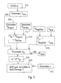
- the flowchart in fig. 2 depicts a method according to a preferred embodiment of the invention.
- the steps in the method can be used in a situation in which an increased output torque from the vehicle drivetrain is desired. This could be, for example, at an acceleration of the vehicle or when the vehicle is moving uphill.
- the method comprises detection by the drivetrain control means 14 of a signal p corresponding to the setting of the accelerator pedal (block 101).
- the drivetrain control means 14 determines (block 104) a corresponding requested crankshaft torque T req according to a predetermined accelerator pedal signal to requested torque correlation.
- a predetermined accelerator pedal signal to requested torque correlation.
- another physical entity such as force or power, is used to represent the requested performance of the drivetrain.
- the drivetrain control means 14 determines an available torque of the engine T Engav based on engine specific parameters, for example engine rotational speed, air temperature, engine temperature and air pressure (block 150).
- the drivetrain control means 14 determines an available ISG torque T ISGav (block 152), based on information of the power source, i.e. the battery, of the ISG 8, which information can include SOC, battery current RMS limits, battery temperature and battery durability and limitations.
- the drivetrain control means 14 calculates an available torque T av as the sum of the available torque of the engine T Engav and the available ISG torque T ISGav (block 154).
- a nominal torque T N is calculated (block 153) as T EngMax - T aux .
- T EngMax is the maximum engine output torque, which has a predetermined value and corresponds to the highest level of torque that can be produced by the engine at current rotational speed, or the torque that the engine is allowed to produce at current rotational speed.
- the engine output torque being dependent upon rotational speed means that T EngMax is dependent upon current selected gear, since the latter determines the rotational speed of the engine. Additionally, T EngMax can be chosen to be dependent upon current engine conditions, such as air temperature, engine temperature and air pressure.
- T aux is an auxiliary load torque corresponding to the maximum effect caused by auxiliary loads in the electricity system 10.
- T aux is dependent upon the engine rotational speed and an auxiliary load power P aux .
- P aux can be chosen to have a fixed predetermined value corresponding to a maximum auxiliary load, including battery charging requirements and loads of electric components.
- a suitable value for P aux in a medium size passenger vehicle is 3-4 kW.
- P aux can be determined according to a predetermined scheme, at which the value of P aux is determined based on the requested torque T req . Thereby, at current operation conditions the priority of electrical components or groups of components are weighted against the torque requirements.
- the drivetrain control means 14 calculates (block 109) an adjustment factor A p for the accelerator pedal signal p, based on the requested torque T req , the available torque T av , the nominal toque T N and a maximum torque T Max .
- the maximum torque T Max equals T EngMax and T ISGMax added together.
- T ISGMax is the highest torque that can be produced by the ISG 8 and is predetermined. Alternatively, T ISGMax can assume some other predetermined value, e.g. a highest torque allowed to be produced by the ISG 8.
- the accelerator pedal signal p is adjusted by the adjustment factor A p (block 110).
- the vehicle speed v is determined in a manner known in the art (block 111). A decision is made by the drivetrain control means 14 based on the vehicle speed v and the adjusted accelerator pedal signal p, if a gear shift should be made in the transmission.
- Fig. 3 and 4 show diagrams related to the determination of the adjustment factor A p for the accelerator pedal signal p (block 109 in fig. 2).
- Input information in fig. 3 is the requested torque T req .
- a value of the adjustment factor A p is given by a line, I or II, which ever gives the highest value of A p for the value of T req .
- Line I corresponds to a constant A p of 1, i.e. no adjustment of the accelerator pedal signal.
- Line II which also could be a curve, corresponds to increasing A p with increasing T req .
- the line II is moved vertically in the diagram in fig. 3.
- the vertical position of the line II is determined by a value of a curve adjustment parameter CA II , which is dependent on the available torque T av , and illustrated by a wide double arrow in fig. 3.
- Fig. 4 depicts the determination of CA II .
- T av equals the maximum torque T Max which, according to the description above, corresponds to the highest level of torque which can be produced by the drivetrain
- CA II is set to zero, which corresponds to the lowest level of the line II in fig. 3.
- T av equals the nominal torque T N which, deduced form the description above, can be said to correspond to the lowest level of torque which can be guaranteed by the drivetrain
- CA II is set to 1. This corresponds to the highest level of the line II in fig. 3.
- the line II in fig. 3 can take an infinite number of or a plurality of vertical positions between two extreme positions.
- the lowest position corresponds to the available torque being equal to the maximum torque at which no adjustment of the pedal signal p is needed, and for all values of T req , A p is set to 1.
- the highest position of the line II corresponds to the available torque being equal to the nominal torque at which no adjustment of the pedal signal p is made for values of T req below T N , but for values of T req above T N , A p is set to a value above 1, and the accelerator pedal signal is adjusted upward.
- the flowchart in fig. 5 depicts a method according to an alternative embodiment of the invention. Many of the steps in the alternative method correspond to steps in the method described in connection to fig. 2 above.
- a detection by the drivetrain control means 14 of a signal p corresponding to the setting of the accelerator pedal is carried out (block 201), and in response thereto, the drivetrain control means 14 determines (block 204) a corresponding requested crankshaft torque T req .
- the requested torque T req is compared to the nominal torque T N (block 205). If the requested torque T req is smaller than the nominal torque T N , the steps above are repeated (blocks 201-205).
- the drivetrain control means 14 determines an available torque of the engine T Engav (block 250), and an available ISG torque T ISGav (block 252), in a manner similar to what has been described above in connection to fig. 2.
- the drivetrain control means 14 calculates (block 209), similar to what has been described above, an adjustment factor A p for the accelerator pedal signal p, the accelerator pedal signal p is adjusted by the adjustment factor A p (block 210) and the vehicle speed v is determined, after which a decision is made by the drivetrain control means, if a gear shift should be made in the transmission.
- accelerator pedal signals form an input parameter for the gear shift schedule and are adjusted to force a downshift, when available torque does not meet requested torque.
- gear shift schedule input parameters can be adjusted to accomplish the same effect.
- the requested torque forms a gear shift schedule input parameter
- an adjustment factor A v can be calculated for the vehicle speed, where the latter forms a gear shift schedule input parameter.
- this can be adjusted by a wheel traction adjustment factor in a similar way to what has been described above.
- Another alternative could include adjusting more than one of the gear shift schedule input parameters.
- gear shift schedule itself can be adjusted.
- the schedule may be adapted, as is known in the art, to control gear shifts at certain vehicle speeds.
- an upper and a lower limit speed is used so that the gear is shifted up and down, respectively, at speeds corresponding to these limit speeds.
- a limit speed can be adjusted so as for the transmission to change gear at a different vehicle speed, than would the limit speeds have been un-adjusted.
- the lower limit speed of a certain gear can be adjusted upwards so as to cause a gear down shift at a higher speed than otherwise.
- gear shift schedule can be altered or replaced.
- the set of gear shift control elements can comprise a plurality of gear shift schedules, whereby the entire schedule is replaced to cause a gear shift to occur at a different speed.
- the invention has been described in relation to an automatic transmission. However, the invention is also applicable on any other type of transmission, where some type of automatic gear control is involved, such as in a automated shifted manual transmission, or a continuously variable transmission (CVT).
- CVT continuously variable transmission
Abstract
Description
- The present invention relates to a method and a system in a vehicle comprising a drivetrain, comprising a drive unit, such as an internal combustion engine, with a motive power output, a transmission, mechanically connected to the motive power output, directly or indirectly, and an electric machine, which can be used at least as a motor, mechanically connected to the motive power output, directly or indirectly, the vehicle further comprising an accelerator control device and drivetrain control means, which is connected to the accelerator control device and the drivetrain, the drivetrain control means being adapted to select a gear of the transmission based on a set of gear shift control elements, including at least one gear shift schedule and at least one gear shift schedule input parameter, and to send at least one signal to the transmission so as to control the gear state of the latter.
- In a vehicle comprising a drivetrain with an automatic transmission, controlled by an electronic control device such as a Transmission Control Module (TCM), the selection of gears in the transmission is made according to a predetermined gear shift schedule, according to which a decision to shift gear can be ordered based on information about, e.g. vehicle speed and accelerator pedal position. For achieving a good fuel economy, the shift schedule can be adapted so that, during an acceleration, gear shifts will occur at a relatively early stage. A problem with this approach is that early gear shifts will decrease the amount of torque of the drivedrain. This problem becomes obvious in situations where a relatively large amount of torque is desired, for example in an acceleration or when the vehicle is moving uphill.
- Vehicle drivetrain systems comprising an internal combustion engine, an automatic transmission and an electric machine, which can be used as a motor, are known in the art, see for example GB2348630A. In vehicles comprising such an electric engine, e.g. an Integrated Starter/Generator (ISG), the latter can be used to provide additional torque in situations where this is desired. However, the amount of torque available from the ISG is dependent on properties of its power source, i.e. batteries. Additionally, the amount of torque from the ISG may not suffice for the drivetrain output rotational speed at hand.
- It is an object of the invention to provide a method and a system in a vehicle comprising a drivetrain, comprising a drive unit, an automatic transmission and an electric machine at which a low fuel consumption can be achieved in combination with a high torque.
- The object of the invention is achieved by a method and a system in a vehicle comprising a drivetrain, comprising a drive unit, such as an internal combustion engine, with a motive power output, a transmission, mechanically connected to the motive power output, directly or indirectly, and an electric machine, which can be used at least as a motor, mechanically connected to the motive power output, directly or indirectly, the vehicle further comprising an accelerator control device and drivetrain control means, which is connected to the accelerator control device and the drivetrain, the drivetrain control means being adapted to select a gear of the transmission based on a set of gear shift control elements, including at least one gear shift schedule and at least one gear shift schedule input parameter, and to send at least one signal to the transmission so as to control the gear state of the latter, whereby the method comprises the steps of receiving at least one signal from the accelerator control device, determining a requested torque of the drivetrain, at least partly based on the signal from the accelerator control device, determining an available torque of the electric machine, determining an available torque of the drivetrain, at least partly based on the available torque of the electric machine, and adjusting the set of gear shift control elements at least partly based on the requested torque and the available torque.
- This will result in a dynamic adaptation of gear shifts based at least partly on torque available from the electric machine. In turn this will optimize the gear shift so that the lowest fuel consumption can be achieved without lowering the torque reserves in situations where these are desired.
- Preferably, the step of adjusting the set of gear shift control elements comprises adjusting at least one of the gear shift schedule input parameters. Thereby, the function of the invention can be added as a "bolt-on" solution onto existing transmission control systems, without changes having to be performed in the latter.
- Preferably, the method comprises the steps of determining nominal torque of the drive unit, comparing the nominal torque of the drive unit to the requested torque and performing said steps of determining an available torque of the electric machine, determining an available torque of the drivetrain and adjusting at least one of the gear shift schedule input parameters, if the nominal torque of the drive unit is lower than the requested torque.
- Thereby, the gear shift schedule input parameter will not be not adjusted if it is established that the torque of the engine alone will suffice to meet the torque demands at hand, which in turn results in reducing fuel consumption. Also, the electric machine will not be activated for additional torque, if it is established that the torque of the engine alone will suffice.
- The invention will be described in greater detail below with the aid of the accompanying drawings, in which
- fig. 1 is a schematic block diagram if a vehicle drivetrain and a control system therefore,
- fig. 2 is a flow diagram of a method according to a preferred embodiment of the invention,
- fig. 3 and 4 are diagrams referring to a step in the method shown in the flowchart in fig. 2, and
- fig. 5 is a flow diagram of a method according to an alternative embodiment of the invention.
- Fig. 1 shows schematically a
vehicle drivetrain 1 and a control system therefore. The drivetrain comprises a drive unit in the form of aninternal combustion engine 2 with a motive power output in the form of a crankshaft, here also referred to as anengine output shaft 5. A hydraulic automatic transmission 4 is indirectly connected to theengine output shaft 5 via an intermediate fluidic torque converter 3, which is adapted to drive a transmission input shaft 6. A transmission output shaft 7 drives the wheels of the vehicle for its propulsion. - The
drivetrain 1 also comprises an electric machine in the form of an integrated starter/generator (ISG) 8, which can be used as an electrical motor and a generator. However, the invention can also be applied where this electric machine is adapted to operate as a motor only. The ISG is connected directly to the engine crankshaft via an ISG output shaft 9, and therefore theISG 8 is adapted to have the same rotational speed as the engine. Alternatively the ISG 8 can be connected to the engine crankshaft indirectly via a gear, so that it is adapted to have a rotational speed different from theengine 2. - Fig. 1 shows the
electric machine 8 as located on a side of theengine 2, being opposite to a side on which the transmission 4 is located. As an alternative theelectric machine 8 is located between theengine 2 and the transmission 4. -
Reference number 10 denotes an electric system of the vehicle. Theelectric system 10 comprises a battery and electricity consuming devices in the vehicle. When the ISG 8 operates as a motor, power is provided to it from the battery. An ISG-controller 801 is connected to, and adapted to control theISG 8. - Vehicle control means, here referred to as drivetrain control means 14 or drive train control device, is a control system adapted to control the
drivetrain 1 by means of a plurality of actuator controls, as is known to the person skilled in the art. The drivetrain control means 14 can comprise an engine control module (ECM) and a transmission control module (TCM). - The drivetrain control means 14 is connected to and adapted, in a manner known in the art, to receive signals from an accelerator control device in the form of an
accelerator pedal 15. The drivetrain control means 14 is also adapted to receive engine condition parameters and to send signals to control the operation of theengine 2. As is known to the person skilled in the art, the drivetrain control means 14 is adapted to determine the engine output torque based on certain predetermined drivetrain parameters, e.g. air pressure, air temperature, engine temperature, and rotational speed. - The drivetrain control means 14 is also adapted, in a manner known in the art, to receive, by means of the ISG-
controller 801, condition parameters of theelectric system 10 of the vehicle. These parameters can include state of charge (SOC) of the battery, battery temperature, and also the electric consumption requirements of electricity consuming devices. Static information about components in the electric system can be stored in the drivetrain control means 14, such as battery durability and battery limitations. - The drivetrain control means 14 is also adapted to send control signals to the ISG-
controller 801, to control the output power, the output torque or the rotational speed of theISG 8, when the latter is operating as an electric motor. - The drivetrain control means 14 is adapted to receive, in a manner known in the art, signals corresponding to transmission condition parameters and to send control signals to the transmission 4. Among other parameters the drivetrain control means 14 is adapted to receive information about the transmission input and output rotational speed.
- The drivetrain control means 14 is adapted to select a gear of the transmission based on a set of gear shift control elements. This set includes a predetermined gear shift schedule and gear shift schedule input parameters. Using the gear shift schedule the drivetrain control means 14 can send signals to the transmission 4 so as to change gear of the latter. The gears are selected based on the gear shift schedule input parameters, which could be values corresponding to the speed of the vehicle, and signals from the
accelerator pedal 15. Instead of accelerator pedal signals a requested torque determined on the basis of the accelerator pedal signals can form a gear shift schedule input parameter. - The flowchart in fig. 2 depicts a method according to a preferred embodiment of the invention. The steps in the method can be used in a situation in which an increased output torque from the vehicle drivetrain is desired. This could be, for example, at an acceleration of the vehicle or when the vehicle is moving uphill. The method comprises detection by the drivetrain control means 14 of a signal p corresponding to the setting of the accelerator pedal (block 101).
- In response to the detection of the accelerator pedal signal p (block 101), the drivetrain control means 14 determines (block 104) a corresponding requested crankshaft torque Treq according to a predetermined accelerator pedal signal to requested torque correlation. Alternatively, instead of torque, another physical entity, such as force or power, is used to represent the requested performance of the drivetrain.
- In a manner known in the art the drivetrain control means 14 determines an available torque of the engine TEngav based on engine specific parameters, for example engine rotational speed, air temperature, engine temperature and air pressure (block 150).
- The drivetrain control means 14 determines an available ISG torque TISGav (block 152), based on information of the power source, i.e. the battery, of the
ISG 8, which information can include SOC, battery current RMS limits, battery temperature and battery durability and limitations. - The drivetrain control means 14 calculates an available torque Tav as the sum of the available torque of the engine TEngav and the available ISG torque TISGav (block 154).
- A nominal torque TN is calculated (block 153) as TEngMax - Taux .
- TEngMax is the maximum engine output torque, which has a predetermined value and corresponds to the highest level of torque that can be produced by the engine at current rotational speed, or the torque that the engine is allowed to produce at current rotational speed. The engine output torque being dependent upon rotational speed means that TEngMax is dependent upon current selected gear, since the latter determines the rotational speed of the engine. Additionally, TEngMax can be chosen to be dependent upon current engine conditions, such as air temperature, engine temperature and air pressure.
- Taux is an auxiliary load torque corresponding to the maximum effect caused by auxiliary loads in the
electricity system 10. Taux is dependent upon the engine rotational speed and an auxiliary load power Paux . Paux can be chosen to have a fixed predetermined value corresponding to a maximum auxiliary load, including battery charging requirements and loads of electric components. A suitable value for Paux in a medium size passenger vehicle is 3-4 kW. - Instead of having a fixed value, Paux can be determined according to a predetermined scheme, at which the value of Paux is determined based on the requested torque Treq . Thereby, at current operation conditions the priority of electrical components or groups of components are weighted against the torque requirements.
- In a manner which will be described in greater detail below with reference to fig. 3 and 4, the drivetrain control means 14 calculates (block 109) an adjustment factor Ap for the accelerator pedal signal p, based on the requested torque Treq , the available torque Tav , the nominal toque TN and a maximum torque TMax . The maximum torque TMax equals TEngMax and TISGMax added together. TISGMax is the highest torque that can be produced by the
ISG 8 and is predetermined. Alternatively, TISGMax can assume some other predetermined value, e.g. a highest torque allowed to be produced by theISG 8. - The accelerator pedal signal p is adjusted by the adjustment factor Ap (block 110).
- The vehicle speed v is determined in a manner known in the art (block 111). A decision is made by the drivetrain control means 14 based on the vehicle speed v and the adjusted accelerator pedal signal p, if a gear shift should be made in the transmission.
- Fig. 3 and 4 show diagrams related to the determination of the adjustment factor Ap for the accelerator pedal signal p (block 109 in fig. 2). Input information in fig. 3 is the requested torque Treq . For each value of Treq a value of the adjustment factor Ap is given by a line, I or II, which ever gives the highest value of Ap for the value of Treq . Line I corresponds to a constant Ap of 1, i.e. no adjustment of the accelerator pedal signal. Line II, which also could be a curve, corresponds to increasing Ap with increasing Treq .
- Depending on the available torque Tav , the line II is moved vertically in the diagram in fig. 3. The vertical position of the line II is determined by a value of a curve adjustment parameter CAII , which is dependent on the available torque Tav , and illustrated by a wide double arrow in fig. 3.
- Fig. 4 depicts the determination of CAII . When Tav equals the maximum torque TMax which, according to the description above, corresponds to the highest level of torque which can be produced by the drivetrain, CAII is set to zero, which corresponds to the lowest level of the line II in fig. 3. When Tav equals the nominal torque TN which, deduced form the description above, can be said to correspond to the lowest level of torque which can be guaranteed by the drivetrain, CAII is set to 1. This corresponds to the highest level of the line II in fig. 3.
- Thus, the line II in fig. 3 can take an infinite number of or a plurality of vertical positions between two extreme positions. The lowest position corresponds to the available torque being equal to the maximum torque at which no adjustment of the pedal signal p is needed, and for all values of Treq , Ap is set to 1. The highest position of the line II corresponds to the available torque being equal to the nominal torque at which no adjustment of the pedal signal p is made for values of Treq below TN , but for values of Treq above TN , Ap is set to a value above 1, and the accelerator pedal signal is adjusted upward.
- The flowchart in fig. 5 depicts a method according to an alternative embodiment of the invention. Many of the steps in the alternative method correspond to steps in the method described in connection to fig. 2 above. Thus, a detection by the drivetrain control means 14 of a signal p corresponding to the setting of the accelerator pedal is carried out (block 201), and in response thereto, the drivetrain control means 14 determines (block 204) a corresponding requested crankshaft torque Treq .
- Thereafter, the requested torque Treq is compared to the nominal torque TN (block 205). If the requested torque Treq is smaller than the nominal torque TN , the steps above are repeated (blocks 201-205).
- The drivetrain control means 14 determines an available torque of the engine TEngav (block 250), and an available ISG torque TISGav (block 252), in a manner similar to what has been described above in connection to fig. 2. The available torque Tav is determined (block 253) as Tav=TEngav+TISGav .
- If the requested torque Treq is greater than the nominal torque TN (block 205), the drivetrain control means 14 thereafter calculates (block 209), similar to what has been described above, an adjustment factor Ap for the accelerator pedal signal p, the accelerator pedal signal p is adjusted by the adjustment factor Ap (block 210) and the vehicle speed v is determined, after which a decision is made by the drivetrain control means, if a gear shift should be made in the transmission.
- The alternative embodiment described in connection to fig. 5 provides for a comparison between the requested and the available torque before the ISG is engaged. This will in turn limit the use of the ISG in cases where torque provided by the engine only suffices.
- In the embodiments described above, accelerator pedal signals form an input parameter for the gear shift schedule and are adjusted to force a downshift, when available torque does not meet requested torque. As an alternative other gear shift schedule input parameters can be adjusted to accomplish the same effect. Thus, where the requested torque forms a gear shift schedule input parameter, this can be adjusted by a requested torque adjustment factor AT , to form an adjusted requested torque as Treq = AT*Treq .
- As a further alternative an adjustment factor Av can be calculated for the vehicle speed, where the latter forms a gear shift schedule input parameter. Thus, an adjusted vehicle speed can be calculated as v = Av *v. Also, where the traction effected by the wheels of the vehicle forms a gear shift schedule input parameter, this can be adjusted by a wheel traction adjustment factor in a similar way to what has been described above.
- Another alternative could include adjusting more than one of the gear shift schedule input parameters.
- As an alternative to adjusting one or more of the gear shift schedule input parameters, other members of the set of gear shift control elements can be adjusted. For example, the gear shift schedule itself can be adjusted. The schedule may be adapted, as is known in the art, to control gear shifts at certain vehicle speeds. For each gear, an upper and a lower limit speed is used so that the gear is shifted up and down, respectively, at speeds corresponding to these limit speeds. Thereby, according to an alternative embodiment of the invention, a limit speed can be adjusted so as for the transmission to change gear at a different vehicle speed, than would the limit speeds have been un-adjusted. For example, the lower limit speed of a certain gear can be adjusted upwards so as to cause a gear down shift at a higher speed than otherwise.
- Alternatively, other values, functions or algorithms of the gear shift schedule can be altered or replaced.
- As a further alternative, the set of gear shift control elements can comprise a plurality of gear shift schedules, whereby the entire schedule is replaced to cause a gear shift to occur at a different speed.
- Above, the invention has been described in relation to an automatic transmission. However, the invention is also applicable on any other type of transmission, where some type of automatic gear control is involved, such as in a automated shifted manual transmission, or a continuously variable transmission (CVT).
Claims (7)
- A method in a vehicle comprising a drivetrain (1), comprising a drive unit (2), such as an internal combustion engine, with a motive power output, a transmission (4), mechanically connected to the motive power output, directly or indirectly, and an electric machine (8), which can be used at least as a motor, mechanically connected to the motive power output, directly or indirectly, the vehicle further comprising an accelerator control device (15) and drivetrain control means (14), which is connected to the accelerator control device (15) and the drivetrain (1), the drivetrain control means (14) being adapted to select a gear of the transmission based on a set of gear shift control elements, including at least one gear shift schedule and at least one gear shift schedule input parameter (p, v), and to send at least one signal to the transmission so as to control the gear state of the latter, characterized by the steps ofreceiving (101, 201) at least one signal (p) from the accelerator control device (15),determining (104, 204) a requested torque (Treq ) of the drivetrain, at least partly based on the signal from the accelerator control device,determining (152, 252) an available torque (TISGav ) of the electric machine,determining (154, 253) an available torque (Tav ) of the drivetrain, at least partly based on the available torque (TISGav ) of the electric machine, andadjusting (110, 210) the set of gear shift control elements at least partly based on the requested torque (Treq ) and the available torque (Tav ).
- A method according to claim 1, characterized in that the step of adjusting (110, 210) the set of gear shift control elements comprises adjusting (110, 210) at least one of the gear shift schedule input parameters.
- A method according to claim 1 or 2, characterized by determining a nominal torque (TN ) of the drive unit (2), comparing (205) the nominal torque (TN ) to the requested torque (Treq ) and performing said steps of determining (252) an available torque of the electric machine (TISGav ), determining (253) an available torque (Tav ) of the drivetrain (1) and adjusting (210) at least one of the gear shift schedule input parameters, if the nominal torque (TN ) of the drive unit is lower than the requested torque (Treq ).
- A method according to any of the preceding claims, characterized by sending at least one signal to the transmission so as to down shift the latter.
- A system in a vehicle comprising a drivetrain (1), comprising a drive unit (2), such as an internal combustion engine, with a motive power output, a transmission (4), mechanically connected to the motive power output, directly or indirectly, and an electric machine (8), which can be used at least as a motor, mechanically connected to the motive power output, directly or indirectly, the vehicle further comprising an accelerator control device (15) and drivetrain control means (14), which is connected to the accelerator control device (15) and the drivetrain (1), the drivetrain control means (14) being adapted to select a gear of the transmission based on a set of gear shift control elements, including at least one gear shift schedule and at least one gear shift schedule input parameter (p, v), and to send at least one signal to the transmission so as to control the gear state of the latter, characterized in that the drivetrain control means is adaptedto receive (101, 201) at least one signal (p) from the accelerator control device (15),to determine (104, 204) a requested torque (Treq ) of the drivetrain, at least partly based on the signal from the accelerator control device,to determine (152, 252) an available torque (TISGav ) of the electric machine,to determine (154, 253) an available torque (Tav ) of the drivetrain, at least partly based on the available torque (TISGav ) of the electric machine, andto adjust (110, 210) the set of gear shift control elements at least partly based on the requested torque (Treq ) and the available torque (Tav ).
- A system according to claim 5, characterized in that the drivetrain control means is adapted to adjust (110, 210) at least one of the gear shift schedule input parameters.
- A system according to claim 5 or 6, characterized in that the drivetrain control means (14) is adapted to send at least one signal to the transmission so as to down shift the latter.
Priority Applications (4)
| Application Number | Priority Date | Filing Date | Title |
|---|---|---|---|
| DE60220987T DE60220987T2 (en) | 2002-04-08 | 2002-04-08 | Control method for a hybrid-powered motor vehicle |
| EP05110259A EP1645449B1 (en) | 2002-04-08 | 2002-04-08 | Method/system for controlling a hybrid vehicle drivetrain |
| DE60229985T DE60229985D1 (en) | 2002-04-08 | 2002-04-08 | Drive system for a hybrid-powered motor vehicle and suitable control method |
| EP02445044A EP1356972B1 (en) | 2002-04-08 | 2002-04-08 | Method for controlling a hybrid vehicle drivetrain |
Applications Claiming Priority (1)
| Application Number | Priority Date | Filing Date | Title |
|---|---|---|---|
| EP02445044A EP1356972B1 (en) | 2002-04-08 | 2002-04-08 | Method for controlling a hybrid vehicle drivetrain |
Related Child Applications (1)
| Application Number | Title | Priority Date | Filing Date |
|---|---|---|---|
| EP05110259A Division EP1645449B1 (en) | 2002-04-08 | 2002-04-08 | Method/system for controlling a hybrid vehicle drivetrain |
Publications (2)
| Publication Number | Publication Date |
|---|---|
| EP1356972A1 true EP1356972A1 (en) | 2003-10-29 |
| EP1356972B1 EP1356972B1 (en) | 2007-07-04 |
Family
ID=28686048
Family Applications (2)
| Application Number | Title | Priority Date | Filing Date |
|---|---|---|---|
| EP02445044A Expired - Fee Related EP1356972B1 (en) | 2002-04-08 | 2002-04-08 | Method for controlling a hybrid vehicle drivetrain |
| EP05110259A Expired - Fee Related EP1645449B1 (en) | 2002-04-08 | 2002-04-08 | Method/system for controlling a hybrid vehicle drivetrain |
Family Applications After (1)
| Application Number | Title | Priority Date | Filing Date |
|---|---|---|---|
| EP05110259A Expired - Fee Related EP1645449B1 (en) | 2002-04-08 | 2002-04-08 | Method/system for controlling a hybrid vehicle drivetrain |
Country Status (2)
| Country | Link |
|---|---|
| EP (2) | EP1356972B1 (en) |
| DE (2) | DE60229985D1 (en) |
Cited By (3)
| Publication number | Priority date | Publication date | Assignee | Title |
|---|---|---|---|---|
| FR2869845A1 (en) * | 2004-05-05 | 2005-11-11 | Bosch Gmbh Robert | Motor vehicle control process, involves predefining set point value of accelerator pedal module`s output value in engine control and converting set point into corresponding value of output value to be transmitted to transmission control |
| WO2006014539A2 (en) | 2004-07-07 | 2006-02-09 | Eaton Corporation | Shift point strategy for hybrid electric vehicle transmission |
| US9718462B2 (en) | 2014-01-10 | 2017-08-01 | Ford Global Technologies, Llc | Hybrid vehicle transmission shift management system and method |
Families Citing this family (2)
| Publication number | Priority date | Publication date | Assignee | Title |
|---|---|---|---|---|
| CN103332193B (en) * | 2013-07-12 | 2015-11-18 | 东风汽车公司 | The engine torque oscillation compensation method of rule-based curve compensation control methods |
| JP6197764B2 (en) | 2014-08-08 | 2017-09-20 | トヨタ自動車株式会社 | Electric vehicle |
Citations (7)
| Publication number | Priority date | Publication date | Assignee | Title |
|---|---|---|---|---|
| US5411449A (en) * | 1992-10-02 | 1995-05-02 | Nissan Motor Co., Ltd. | Gear shift control apparatus |
| US5564400A (en) * | 1991-04-17 | 1996-10-15 | Mazda Motor Corporation | System for controlling driving power for a supercharged automotive vehicle |
| EP0903258A2 (en) * | 1997-09-17 | 1999-03-24 | Honda Giken Kogyo Kabushiki Kaisha | Control system for hybrid vehicle |
| US5935040A (en) * | 1996-07-23 | 1999-08-10 | Toyota Jidosha Kabushiki Kaisha | Hybrid vehicle drive system adapted to produce substantially constant vehicle drive force under the same vehicle running condition, even in different modes of operation |
| US6110066A (en) * | 1998-02-05 | 2000-08-29 | Southwest Research Institute | Parallel hybrid drivetrain |
| EP1101650A2 (en) * | 1999-11-19 | 2001-05-23 | Toyota Jidosha Kabushiki Kaisha | Control apparatus for transmission-equipped hybrid vehicle |
| EP1160119A1 (en) * | 1999-02-08 | 2001-12-05 | Toyota Jidosha Kabushiki Kaisha | Vehicle braked by motor torque and method of controlling the vehicle |
Family Cites Families (1)
| Publication number | Priority date | Publication date | Assignee | Title |
|---|---|---|---|---|
| WO2000013927A2 (en) | 1998-09-09 | 2000-03-16 | Luk Lamellen Und Kupplungsbau Gmbh | Interaction between a drive train and an electric machine with several self-adjusting speed increasing ratios |
-
2002
- 2002-04-08 EP EP02445044A patent/EP1356972B1/en not_active Expired - Fee Related
- 2002-04-08 DE DE60229985T patent/DE60229985D1/en not_active Expired - Lifetime
- 2002-04-08 DE DE60220987T patent/DE60220987T2/en not_active Expired - Lifetime
- 2002-04-08 EP EP05110259A patent/EP1645449B1/en not_active Expired - Fee Related
Patent Citations (7)
| Publication number | Priority date | Publication date | Assignee | Title |
|---|---|---|---|---|
| US5564400A (en) * | 1991-04-17 | 1996-10-15 | Mazda Motor Corporation | System for controlling driving power for a supercharged automotive vehicle |
| US5411449A (en) * | 1992-10-02 | 1995-05-02 | Nissan Motor Co., Ltd. | Gear shift control apparatus |
| US5935040A (en) * | 1996-07-23 | 1999-08-10 | Toyota Jidosha Kabushiki Kaisha | Hybrid vehicle drive system adapted to produce substantially constant vehicle drive force under the same vehicle running condition, even in different modes of operation |
| EP0903258A2 (en) * | 1997-09-17 | 1999-03-24 | Honda Giken Kogyo Kabushiki Kaisha | Control system for hybrid vehicle |
| US6110066A (en) * | 1998-02-05 | 2000-08-29 | Southwest Research Institute | Parallel hybrid drivetrain |
| EP1160119A1 (en) * | 1999-02-08 | 2001-12-05 | Toyota Jidosha Kabushiki Kaisha | Vehicle braked by motor torque and method of controlling the vehicle |
| EP1101650A2 (en) * | 1999-11-19 | 2001-05-23 | Toyota Jidosha Kabushiki Kaisha | Control apparatus for transmission-equipped hybrid vehicle |
Cited By (6)
| Publication number | Priority date | Publication date | Assignee | Title |
|---|---|---|---|---|
| FR2869845A1 (en) * | 2004-05-05 | 2005-11-11 | Bosch Gmbh Robert | Motor vehicle control process, involves predefining set point value of accelerator pedal module`s output value in engine control and converting set point into corresponding value of output value to be transmitted to transmission control |
| WO2006014539A2 (en) | 2004-07-07 | 2006-02-09 | Eaton Corporation | Shift point strategy for hybrid electric vehicle transmission |
| WO2006014539A3 (en) * | 2004-07-07 | 2006-04-13 | Eaton Corp | Shift point strategy for hybrid electric vehicle transmission |
| US7463962B2 (en) | 2004-07-07 | 2008-12-09 | Eaton Corporation | Shift point strategy for hybrid electric vehicle transmission |
| CN1985109B (en) * | 2004-07-07 | 2010-10-27 | 易通公司 | Shift point strategy for hybrid electric vehicle transmission |
| US9718462B2 (en) | 2014-01-10 | 2017-08-01 | Ford Global Technologies, Llc | Hybrid vehicle transmission shift management system and method |
Also Published As
| Publication number | Publication date |
|---|---|
| EP1645449A3 (en) | 2006-04-19 |
| DE60220987D1 (en) | 2007-08-16 |
| DE60220987T2 (en) | 2007-10-25 |
| EP1645449A2 (en) | 2006-04-12 |
| EP1356972B1 (en) | 2007-07-04 |
| DE60229985D1 (en) | 2009-01-02 |
| EP1645449B1 (en) | 2008-11-19 |
Similar Documents
| Publication | Publication Date | Title |
|---|---|---|
| EP0940287B1 (en) | Drive control system for hybrid vehicles | |
| CN100412419C (en) | Shift through neutral control in an electrically variable transmission | |
| JP3375123B2 (en) | Car drive train control device | |
| JP4494266B2 (en) | Shift control device for hybrid vehicle | |
| US8050831B2 (en) | Vehicle engine speed control for a continuously variable transmission | |
| CN101612936B (en) | Regulation and control of output torque of transmission in hybrid power electrical vehicle | |
| US20070205735A1 (en) | Control device for a hybrid electric vehicle | |
| US8545365B2 (en) | Vehicular power transmission control apparatus | |
| US8323145B2 (en) | Hybrid powertrain optimum ratio selection | |
| US8210985B2 (en) | Vehicular power transmission control apparatus | |
| CN104908746A (en) | Method and apparatus for controlling a powertrain system during coasting | |
| KR19990083523A (en) | Control system of vehicle having continuously variable transmission | |
| US8630778B2 (en) | Controlling a throttle for fuel cut acquisition | |
| JP2006076566A (en) | Device and method for controlling and regulating component of hybrid power train in automobile | |
| CN111016873B (en) | Energy management method and system based on steady-state engine strategy | |
| CN107662600B (en) | Torque modification during a hybrid vehicle upshift | |
| US6401016B1 (en) | Vehicle control device | |
| JP5201786B2 (en) | Engine output control device | |
| EP1356972B1 (en) | Method for controlling a hybrid vehicle drivetrain | |
| JP2010519483A (en) | How to operate an automatic or semi-automatic transmission of a large vehicle in idling mode | |
| US20040254046A1 (en) | Control system for hybrid drive unit | |
| US9956948B2 (en) | Systems and methods for improving gear shifts | |
| KR102371015B1 (en) | Method for controlling hybrid electric vehicle | |
| JPH09308007A (en) | Controller of hybrid vehicle | |
| JP2007132238A (en) | Engine power control device in start of vehicle |
Legal Events
| Date | Code | Title | Description |
|---|---|---|---|
| PUAI | Public reference made under article 153(3) epc to a published international application that has entered the european phase |
Free format text: ORIGINAL CODE: 0009012 |
|
| AK | Designated contracting states |
Kind code of ref document: A1 Designated state(s): AT BE CH CY DE DK ES FI FR GB GR IE IT LI LU MC NL PT SE TR |
|
| AX | Request for extension of the european patent |
Extension state: AL LT LV MK RO SI |
|
| 17P | Request for examination filed |
Effective date: 20040410 |
|
| AKX | Designation fees paid |
Designated state(s): DE GB SE |
|
| 17Q | First examination report despatched |
Effective date: 20040615 |
|
| GRAP | Despatch of communication of intention to grant a patent |
Free format text: ORIGINAL CODE: EPIDOSNIGR1 |
|
| RTI1 | Title (correction) |
Free format text: METHOD FOR CONTROLLING A HYBRID VEHICLE DRIVETRAIN |
|
| GRAS | Grant fee paid |
Free format text: ORIGINAL CODE: EPIDOSNIGR3 |
|
| RAP1 | Party data changed (applicant data changed or rights of an application transferred) |
Owner name: FORD GLOBAL TECHNOLOGIES, LLC |
|
| GRAA | (expected) grant |
Free format text: ORIGINAL CODE: 0009210 |
|
| RAP1 | Party data changed (applicant data changed or rights of an application transferred) |
Owner name: FORD GLOBAL TECHNOLOGIES, LLC |
|
| AK | Designated contracting states |
Kind code of ref document: B1 Designated state(s): DE GB SE |
|
| REG | Reference to a national code |
Ref country code: GB Ref legal event code: FG4D |
|
| REF | Corresponds to: |
Ref document number: 60220987 Country of ref document: DE Date of ref document: 20070816 Kind code of ref document: P |
|
| REG | Reference to a national code |
Ref country code: SE Ref legal event code: TRGR |
|
| PLBE | No opposition filed within time limit |
Free format text: ORIGINAL CODE: 0009261 |
|
| STAA | Information on the status of an ep patent application or granted ep patent |
Free format text: STATUS: NO OPPOSITION FILED WITHIN TIME LIMIT |
|
| 26N | No opposition filed |
Effective date: 20080407 |
|
| REG | Reference to a national code |
Ref country code: GB Ref legal event code: 732E Free format text: REGISTERED BETWEEN 20111020 AND 20111025 |
|
| REG | Reference to a national code |
Ref country code: DE Ref legal event code: R082 Ref document number: 60220987 Country of ref document: DE Representative=s name: GRUENECKER, KINKELDEY, STOCKMAIR & SCHWANHAEUS, DE |
|
| REG | Reference to a national code |
Ref country code: DE Ref legal event code: R082 Ref document number: 60220987 Country of ref document: DE Representative=s name: GRUENECKER, KINKELDEY, STOCKMAIR & SCHWANHAEUS, DE Effective date: 20120207 Ref country code: DE Ref legal event code: R081 Ref document number: 60220987 Country of ref document: DE Owner name: VOLVO CAR CORPORATION, SE Free format text: FORMER OWNER: FORD GLOBAL TECHNOLOGIES, LLC, DEARBORN, US Effective date: 20120207 Ref country code: DE Ref legal event code: R081 Ref document number: 60220987 Country of ref document: DE Owner name: VOLVO CAR CORPORATION, SE Free format text: FORMER OWNER: FORD GLOBAL TECHNOLOGIES, LLC, DEARBORN, MICH., US Effective date: 20120207 Ref country code: DE Ref legal event code: R082 Ref document number: 60220987 Country of ref document: DE Representative=s name: GRUENECKER PATENT- UND RECHTSANWAELTE PARTG MB, DE Effective date: 20120207 |
|
| PGFP | Annual fee paid to national office [announced via postgrant information from national office to epo] |
Ref country code: GB Payment date: 20150420 Year of fee payment: 14 Ref country code: SE Payment date: 20150424 Year of fee payment: 14 |
|
| PGFP | Annual fee paid to national office [announced via postgrant information from national office to epo] |
Ref country code: DE Payment date: 20160411 Year of fee payment: 15 |
|
| REG | Reference to a national code |
Ref country code: SE Ref legal event code: EUG |
|
| GBPC | Gb: european patent ceased through non-payment of renewal fee |
Effective date: 20160408 |
|
| PG25 | Lapsed in a contracting state [announced via postgrant information from national office to epo] |
Ref country code: GB Free format text: LAPSE BECAUSE OF NON-PAYMENT OF DUE FEES Effective date: 20160408 |
|
| PG25 | Lapsed in a contracting state [announced via postgrant information from national office to epo] |
Ref country code: SE Free format text: LAPSE BECAUSE OF NON-PAYMENT OF DUE FEES Effective date: 20160409 |
|
| REG | Reference to a national code |
Ref country code: DE Ref legal event code: R119 Ref document number: 60220987 Country of ref document: DE |
|
| PG25 | Lapsed in a contracting state [announced via postgrant information from national office to epo] |
Ref country code: DE Free format text: LAPSE BECAUSE OF NON-PAYMENT OF DUE FEES Effective date: 20171103 |