EP1354558A2 - Intracardiac suture device - Google Patents
Intracardiac suture device Download PDFInfo
- Publication number
- EP1354558A2 EP1354558A2 EP03008029A EP03008029A EP1354558A2 EP 1354558 A2 EP1354558 A2 EP 1354558A2 EP 03008029 A EP03008029 A EP 03008029A EP 03008029 A EP03008029 A EP 03008029A EP 1354558 A2 EP1354558 A2 EP 1354558A2
- Authority
- EP
- European Patent Office
- Prior art keywords
- shaft
- distal end
- holding means
- suture
- suture needle
- Prior art date
- Legal status (The legal status is an assumption and is not a legal conclusion. Google has not performed a legal analysis and makes no representation as to the accuracy of the status listed.)
- Granted
Links
Images


Classifications
-
- A—HUMAN NECESSITIES
- A61—MEDICAL OR VETERINARY SCIENCE; HYGIENE
- A61B—DIAGNOSIS; SURGERY; IDENTIFICATION
- A61B17/00—Surgical instruments, devices or methods, e.g. tourniquets
- A61B17/04—Surgical instruments, devices or methods, e.g. tourniquets for suturing wounds; Holders or packages for needles or suture materials
- A61B17/0469—Suturing instruments for use in minimally invasive surgery, e.g. endoscopic surgery
-
- A—HUMAN NECESSITIES
- A61—MEDICAL OR VETERINARY SCIENCE; HYGIENE
- A61B—DIAGNOSIS; SURGERY; IDENTIFICATION
- A61B17/00—Surgical instruments, devices or methods, e.g. tourniquets
- A61B17/04—Surgical instruments, devices or methods, e.g. tourniquets for suturing wounds; Holders or packages for needles or suture materials
- A61B17/0482—Needle or suture guides
-
- A—HUMAN NECESSITIES
- A61—MEDICAL OR VETERINARY SCIENCE; HYGIENE
- A61B—DIAGNOSIS; SURGERY; IDENTIFICATION
- A61B17/00—Surgical instruments, devices or methods, e.g. tourniquets
- A61B17/00234—Surgical instruments, devices or methods, e.g. tourniquets for minimally invasive surgery
- A61B2017/00238—Type of minimally invasive operation
- A61B2017/00243—Type of minimally invasive operation cardiac
Definitions
- the present invention relates to an intracardiac suture device for use in treatment of intracardiac defects by suturing the defective portion with a suture needle.
- the heart-lung machine is a device, which performs hemoperfusion instead of the heart of a patient during the stopped period of the pumping action of the heart and acts the breathing function for the lung by prosecution of the gas exchange in the blood.
- the heart-lung machine generally comprises four main components, i.e., a blood pump, an oxygenator, a heat exchanger and a reservoir.
- the heart-lung machines have been used widely as auxiliary measures for extracorporeal circulation in open-heart surgery.
- auxiliary measures for supplementary circulation when any bad circulation of the internal organ and/or organization arises from considerable decrease in the pumping action of the heart, or auxiliary measures for gas exchange when the function of the patient's lung is considerably damaged.
- the lung-heart machines are used in membrane oxygenator-assisted extracorporeal circulation (ECMO), and as auxiliary measures for extracorporeal circulation in thoracic aortic aneurysm surgery.
- ECMO membrane oxygenator-assisted extracorporeal circulation
- the present invention has been made on the basis of an idea that the minimally invasive surgery can be achieved by a method of introducing a suture device into the heart of a patient through a sheath after surgically incising the chest region of a patent.
- an intracardiac suture device comprising:
- the second shaft assembly is rotatable in the first shaft assembly.
- the above visual monitoring means may be an endoscope or ultrasonic transducer.
- the second connector may be provided with a pair of rotationally symmetrical protrusion extending from the peripheral portion toward the distal end thereof, and the first connector may be provided on its proximal end side with a pair of recesses for holding the protrusions of the second connector.
- the second shaft is movable between a position where the protrusions are respectively fitted in the recesses and a position where the protrusions are disengaged from the recesses.
- Either or both connectors of the first and second shaft assemblies may be provided with a side tube for infusion of heparin, a saline solution or the like.
- an intracardiac suture device which comprises: a first shaft assembly 1 comprising a first shaft 11 and a first suture needle-holding means (or a first suture needle gripper) 4; a second shaft assembly 2 comprising a second shaft 21 having first and second lumens 211, 212 and a distal end closed by a transparent covering member 23; a third shaft assembly 3 comprising a hollow third shaft 31 and a handling portion 33; and a puncture assembly 5 provided with a second suture needle-holding means 51.
- the second suture needle-holding means 51 being removably arranged in the distal end of the third shaft 31; and an endoscope 8; wherein a suture needle 6 is adapted to be transferable between the first suture needle-holding means 4 and the second suture needle-holding means 51 when the third shaft 31 is slid to the distal end of the covering member 23 after sliding of the second shaft 21 to a position where a suture site is clamped between the covering member 23 and the first suture needle-holding means 4.
- the first shaft assembly 1 comprises a first shaft 11 with a lumen 111 extending from a proximal end thereof to a distal end thereof and passing therethrough, a first suture needle-holding means 4 coaxially provided at a distal end of the first shaft 11 and spaced therefrom, and a first connector 12 provided on the proximal end of the first shaft 11 and having a hemostatic valve.
- the first shaft 11 is a tubular member made of a metal such as stainless steel and brass, meshed or coiled stainless steel, or a synthetic resin such as fluoroplastic (e.g., polytetrafluoroethylene), polypropylene, polyethylene, polyamide, polyethylene terephthalate, polyurethane and the like.
- Th first shaft 11 has lumen 111, which passes therethrough from the distal end thereof to the proximal end thereof.
- the second shaft assembly 2 is slidably and rotatably attached to the first shaft assembly 1 by inserting the second shaft 21 into the lumen 111 of the first shaft 11 through the connector 12 provided on the proximal end of the first shaft 11.
- the first connector 12 is a tubular member generally made of a synthetic resin such as polypropylene, ABS (acrylonitrile-butadiene-styrene) resin, polyvinyl chloride, polyethylene and polyethylene terephthalate, or a metal such as stainless steel, brass and the like.
- the first connector 12 is provided at a proximal end thereof with a through-hole 121 for insertion of the second shaft 21.
- the first connector 12 is provided with a stepped lumen of which a proximal portion has an inner diameter smaller than that of a distal portion thereof.
- the first connector 12 is provided in a sidewall thereof with a pair of opposing grooves 122 into which a pair of protrusions 221 of the connector 22 of the second shaft 21 mentioned below.
- the first connector 12 is also provided in an interior thereof with a hemostatic means (not illustrated in the drawings) for preventing leakage of the blood during operation.
- the first suture needle-holding means 4 may be arranged in a needle-holding means housing 13, which is formed as an integral part of a tube forming the first shaft 11.
- the needle-holding means housing 13 is provided at the distal end of the tube, which forms the first shaft 11.
- the needle-holding means housing 13 is spaced from the distal end of the first shaft 11 by a notch 14 formed in the distal end of the first shaft 11.
- the notch 14 has a predetermined length and a depth sufficiently greater than a radius of the first shaft 11.
- the needle-holding means housing 13 is closed at the distal end thereof by a closing member 43 to which the first suture needle-holding means 4, is fixed.
- the first suture needle-holding means 4 is arranged in the needle-holding means housing 13 such that the distal end thereof is directed to the first shaft 11.
- the first suture needle-holding means 4 may be comprised of, as illustrated in Fig. 4, a flexible hollow member 41 including a needle-holding portion with an inner diameter slightly smaller than a diameter of the suture needle 6.
- the hollow member 41 is provided at a distal end thereof with a needle guide port 42, and at a proximal side thereof with plural slits 411 extending in the longitudinal direction thereof.
- the hollow members 41 of the fist suture needle-holding means 4 may be made of a metal such as stainless steel, brass and the like or a flexible resin such as polypropylene, polyethylene, polyamids and the like.
- the needle guide port 42 may be made of a synthetic resin such as fluoroplastic (e.g., polytetrafluoroethylene), polypropylene, polyethylene, polyamide, polyethylene terephthalate, polyurethane and the like.
- the second shaft assembly 2 comprises a second shaft 21 having first and second lumens 211, 212 extending from a distal end thereof to a proximal end thereof and passing therethrough, a transparent cover member 23 attached to the distal end of the second shaft 21 to close the distal end of the second lumen 212, and a connector 22 attached to the proximal end of the second shaft 21 and having a hemostatic valve provided therein.
- the second shaft 21 is movable by sliding movement in the direction of the first suture needle-holding means 4 and is rotatable within the first shaft assembly 1.
- the first lumen 211 houses the puncture assembly 5 slidably inserted therein, while the second lumen 212 houses an endoscope arranged therein.
- Any cover member may constitute the cover member 23 if it can protect the endoscope.
- a non-limitative preferred cover member is the one having a lumen 231 communicated with the first lumen 211 at a proximal end thereof and being open at a distal end thereof, and a lumen 232 communicated with the second lumen 212 at a proximal end thereof and closed at a distal end thereof.
- the cover member 23 may be made of a transparent plastic such as, for example, acrylic resin, polystyrene, polypropylene, polymethyl methacrylate, polyamide, polyester, polycarbonate and the like.
- the second shaft 21 is a slender hollow tubular member made of the same material as that used for the first shaft 11.
- the third shaft assembly 3 (actually, the third shaft 31 through the connector 22) and endoscope 8 are slidably inserted, respectively.
- the second connector 22 is a tubular member made of the same material as that of the connector 12, and is provided at a proximal end thereof with an insertion hole (not illustrated in the drawings) for the third shaft 311 and endoscope 8.
- the connector 22 is further provided in its interior with a hemostatic means (not illustrated in the drawings) for preventing the blood from leakage during operation.
- the third shaft assembly 3 comprises a hollow third shaft 31 and a handling portion 33 provided at a proximal end of the third shaft 31.
- the third shaft 31 is a slender tubular member made of the same material as that of the first shaft 11 and having a lumen 311 passing therethrough from a distal end thereof to a proximal end thereof.
- the third shaft 31 is provided at the proximal end thereof with the handling portion 33 for actuating it back and forth by sliding movement, through which an operating rod 52 of an after-mentioned second suture needle-holding means 51 is inserted movably back and forth.
- the puncture assembly 5 is slidably arranged in the third shaft assembly 3.
- the puncture assembly 5 comprises a second suture needle-holding means 51, and a slender hollow operating rod 52 connected to a proximal end of the second suture needle-holding means 51.
- the second suture needle-holding means 51 is positioned in the distal end of the third shaft 31 and adapted to be put in and out the lumen 311 of the third shaft 31.
- the operating rod 52 is movably arranged in the lumen 311 of the third shaft 31.
- the second suture needle-holding means 51 comprises a flexible hollow member 55 having an inner diameter slightly larger than the diameter of the suture needle 6 and an outer diameter smaller than the inner diameter of the third shaft 31.
- the hollow member 55 is provided at the distal end thereof with a enlarged head portion 552, which has an outer diameter greater than the inner diameter of the third shaft 31 and is tapered toward the proximal end thereof.
- the hollow member 55 is provided with plural slits 551 longitudinally extending from the distal end of the head portion 552 towards the proximal end of hollow member 55.
- the hollow operating rod 52 slidably arranged in the lumen 311 of the third shaft 31 is connected to the proximal end of the hollow member 55.
- the enlarged head portion 552 is adapted to hold the suture needle 6 therein by reduction of the inner diameter thereof when the enlarged head portion 552 is housed in the third shaft 31.
- the third shaft 31 is preferably provided with an annular rib 312 at the distal portion of the lumen 311 thereof to prevent the enlarged head portion 552 from movement toward the proximal side thereof at the time of seating of the enlarged head portion 552 in the third shaft 31.
- the enlarged head portion 552 When the enlarged head portion 552 is pushed out of the lumen of the third shaft 31, the enlarged head portion 552 may be returned to the lumen of the third shaft 31 by manually operating the operating rod 52. Alternately, as illustrated in Fig. 4, the enlarged head portion 552 may be returned automatically to its original position by providing an auto-return mechanism, which comprises, for example, a flange 553 provided at the proximal end of the hollow member 55, and a coil spring 53 arranged around the hollow member 55 and between the flange 553 and the annular rib 312 so that the coil spring 53 is compressed when the operating rod 52 is pushed forward in the third shaft 31, and then restored by the restoring force of the coil spring 53 to automatically house the enlarged head portion 552 to the lumen 311 of the third shaft 31.
- an auto-return mechanism which comprises, for example, a flange 553 provided at the proximal end of the hollow member 55, and a coil spring 53 arranged around the hollow member 55 and between
- the operating rod 52 may be provided at a proximal end thereof with a handling portion 54, which is adapted to be moved forward and backward with respect to the handling portion 33 of the third shaft assembly 3.
- the suture needle 6 is transferred between the first suture needle-holding means 4 and the second suture needle-holding means 51 when the third shaft 31 is moved to the distal end of the second shaft 21 that had been moved beyond the distal end of the first shaft 1 to a position where a suture site is held between the second shaft 21 and the first suture needle-holding means 4.
- first connector 12 and/or second connector 22 may be provided with a side tube 222 for infusion of heparin, saline for irrigation and the like.
- the hollow member 55 of the second suture needle-holding means 51 may be made of, without being limited to, the same materials as those used for the hollow member 41 of the first suture needle-holding means 4 as the hollow member 55 has the same structure and function as those of the hollow member 41 of the first suture needle-holding means 4.
- closure of defects may be carried out in the manner mentioned below with reference to Figs. 6 to 13.
- the heart is exposed by surgical incision of the chest of a patient to check the position of the heart and then punctured at an appropriate part of the heart (usually, the right auricle).
- a sheath (not illustrated in the drawings) for insertion of an intracardiac suture device is inserted into the heart through the punctured part thereof until a leading end of the sheath reaches to a position near a suture site.
- the intracardiac suture device illustrated in Figs. 1 and 2 is inserted into the sheath and guided to the position near the suture site.
- the third shaft 31 and the second suture needle-holding means 51of the suture device have been set so as to have a physical relationship as illustrated in Fig. 4.
- the distal end of the suture device is protruded from the sheath to locate the first suture needle-holding means 4 within a defect aperture DA of the heart so that the notch 14 is located in the defect aperture DA.
- the second shaft assembly 2 is then pushed manually toward the first shaft assembly 1 to hold a tissue T surrounding the defect aperture DA between the distal end of the second shaft 21 and the needle-holding means housing 13, while checking out the physical relationship between the device and the suture site in the heart with the endoscope 8.
- the third shaft assembly 3 is moved forward along with the second shaft assembly 2 (Fig. 7).
- the third shaft assembly 3 is pushed toward the second shaft assembly 2 by operating the first handling portion 33, with the result that the second puncture needle-holding means 51 housed in the third shaft 31 is moved forward along with the third shaft 31 to puncture the tissue T.
- the distal portion of the puncture needle 6 is inserted into the first suture needle-holding means 4 and gripped therein at the distal end thereof (Fig. 8). At that time, it is possible to observe the condition of the suture needle 6 that punctured the tissue T.
- the handling portion 33 When the handling portion 33 is moved to a position adjacent to the handling portion 54 (an adjacent condition) by holding the handling portion 33 and 54, the third shaft assembly 3 is backed toward the puncture assembly 5 since the puncture assembly 5 is locked to the first suture needle-holding means 4 by the suture needle 6. At that time, the enlarged head portion 552 is unsheathed from the third shaft 31 and thus the hollow member 55 is released from the compression pressure of the third shaft 31. For this reason, the hollow member 55 is returned to the uncompressed condition where the inner diameter of the hollow member 55 is larger than the outer diameter of the suture needle 6, and the suture needle 6 is released from the second suture needle-holding means 51 (cf. Fig. 9).
- the coil spring 53 is compressed by the backward movement of the handling portion 33.
- the first shaft assembly 1 is manually pushed forward over the second shaft assembly 2 as it stands, with the result that the suture needle 6 is passed through the tissue T and transferred to the first suture needle-holding means 4 on the opposite side of the second suture needle-holding means 51 with respect to the tissue T, as illustrated in Fig. 10.
- the whole suture device is somewhat moved backward and the handling portion 54 of the puncture assembly 5 is released from the hand while holding the handling portion 33 by hand, so that the second suture needle holding means 51 is moved backward by the restoring force of the coil spring 53.
- the enlarged head portion 552 is pulled in the lumen 311 of the third shaft 31.
- the handling portions 33 and 54 are returned from the adjacent condition to the original spaced condition.
- the whole of the suture device is moved to bring out the tissue T from the notched portion 14, as illustrated in Fig. 11.
- the second shaft assembly 2 is pushed forward so that it take the position approximately the same position illustrated in Fig. 7.
- the handling portion 54 of the puncture assembly 5 is moved to a position closed to the handling portion 33 while holding the operating portions 33 and 54, so that the enlarged head portion 552 of the second needle-holding means 51 is unsheathed from the third shaft 31 and the hollow member 55 is released from the compression pressure of the third shaft 31.
- the hollow member 55 is returned to the uncompressed condition where the inner diameter of the hollow member 55 is larger than the outer diameter of the suture needle 6.
- the coil spring 53 is being compressed.
- the third shaft assembly 3 is advanced in connection with the second shaft assembly 2 by pushing the handling portion 33, so that the suture needle 6 is received by the second suture needle-holding means 51 as illustrated in Fig. 12.
- the third shaft assembly 3 is moved forward by the restoring force of the coil spring 53.
- the enlarged head portion 552 is received in the third shaft 31 and the hollow member 55 is compressed by the third shaft 31 to make the inner diameter of the hollow member 55 smaller than the outer diameter of the suture needle 6.
- the suture needle 6 is held by the suture needle-holding means 51.
- the first shaft assembly 1 is pushed forward manually in connection with the second shaft assembly 2, the suture needle 6 is transferred to the second suture needle-holding means 51 and brought to the condition as illustrated in Fig. 13.
- the closure of defect is completed by repeating the above procedures several times, and carrying out ligature and cutting of the suture with a special purpose device.
- the use of the intracardiac suture device of the present invention makes it possible to perform a minimally invasive operation for suturing intracardiac defects without use of any artificial heart-lung system.
- the present invention makes it possible to perform intracardiac operations certainly and safely at a lower cost as compared with the conventional operations using any artificial heart-lung system.
- the present invention makes it possible to minimize risk of complications after the operation since the recovery time after operation is reduced to about one day, which is very short as compared with the recovery time of more than one week.
- the present device is easy to operate and contribute to reduce burdens for an operator.
Abstract
Description
- The present invention relates to an intracardiac suture device for use in treatment of intracardiac defects by suturing the defective portion with a suture needle.
- For treatment of intracardiac defects such as atrial septal defect, ventricular septal defect and valvular disease, it is general practice to perform surgical operations with an artificial heart-lung machine (i.e., an extracorporeal circulation system). The heart-lung machine is a device, which performs hemoperfusion instead of the heart of a patient during the stopped period of the pumping action of the heart and acts the breathing function for the lung by prosecution of the gas exchange in the blood. The heart-lung machine generally comprises four main components, i.e., a blood pump, an oxygenator, a heat exchanger and a reservoir. The heart-lung machines have been used widely as auxiliary measures for extracorporeal circulation in open-heart surgery. Further, they have also been used as auxiliary measures for supplementary circulation when any bad circulation of the internal organ and/or organization arises from considerable decrease in the pumping action of the heart, or auxiliary measures for gas exchange when the function of the patient's lung is considerably damaged. In addition, the lung-heart machines are used in membrane oxygenator-assisted extracorporeal circulation (ECMO), and as auxiliary measures for extracorporeal circulation in thoracic aortic aneurysm surgery.
- In the first era of cardiac surgery, surgical operations of pulsating hearts have been carried out blindly by the feel and thus the safety has come up as a serious problem before development of an artificial heart-lung machine. In 1953, Dr. Gibbon succeeded in a first cardiac surgery with an artificial heart-lung machine. From that time, the safety of the cardiac surgery has been improved by various improvements in heart-lung machines and development of myocardial depressants. Now, the use of extracorporeal circulation makes it possible to perform the cardiac surgery safely.
- However, even at the present state of the art, the cardiac surgeries with the heart-lung machines are at risk for the following postoperative complications:
- (1) Complication in the brain: Cerebral hypoxemia or cerebral edema resulting from incorrect perfusion. Cerebral infarction due to embolization by of tissue fragments into the blood caused by interfusion of intake-air into extracorporeal circulation in the heart-lung machine or by operation to connect the heart-lung machine to the patient;
- (2) Complication in the lung: hypoxemia or ventilatory insufficiency caused by various inflammatory substances, which are activated by the heart-lung machine;
- (3) Renal dysfunction: Acute renal failure caused by decrease in renal blood flow due to use of the heart-lung machine;
- (4) Blood cell injuries: Blood cell injuries are taken place by performing perfusion of the blood into the artificial, i.e., heart-lung machine. This may cause renal dysfunction, resulting in necessity of blood infusion;
- (5) Postoperative bleeding: Postoperative bleeding may occur by the disorder of the in-vivo hemostatic function caused by the heart-lung machine;
- (6) Aortic dissection: By insertion of an arterial inflow cannula into the aorta, the endothelium of the blood vessel may be injured and induced the acute aortic dissection. This complication is extremely serious condition and death rate of a patient is high;
- (7) Other complications: Postoperative infective diseases and multiple organ failure caused by decrease of immunoreaction.
-
- It is often the case that these complications cause systemic inflammation even if the patient's condition is not severe and the length of postoperative stay in the hospital takes one week at the least. Further, the artificial circulation passage used in operation is of disposable, a high medical cost presents problems for the patients.
- Recently, a tendency to avoid the side effects due to use of the artificial hear-lung is seen in the field of coronary artery bypass, and operations without use of the artificial hear-lung machine have been popularized. In particularly, minimally invasive surgery employing an endoscope is widely used and has become of major interest lately because of low occurrence of complications and rapid recovery after operation.
- Even in the field of cardiac surgery, there is an increasing demand for intracardiac surgeries which car. be performed without use of any hear-lung machine. It is however, impossible to stop the beat of the heart. Further, it is pointed out that there would be considerable difficulty in use of the endoscope since the blood and beating heart obstructs the view from the endoscope. Commercially available catheter devices such as "Amplatzer" (brand name), "Angelwing" (brand name) are applied for treatment of atrial septal defects. These devices are designed for uniformly distributed defects as targets. Thus, it is difficult with such devices to treat the intracardiac defects since these defects vary with the individual patient. For these reasons, there is a great demand for any breakthrough for realizing cardiac surgery without use of any artificial heart-lung machine.
- It is therefore an object of the present invention to provide an intracardiac suture device for performing minimally invasive cardiac surgery on intracardiac defects without use of any artificial heart-lung system.
- The present invention has been made on the basis of an idea that the minimally invasive surgery can be achieved by a method of introducing a suture device into the heart of a patient through a sheath after surgically incising the chest region of a patent.
- According to the present invention, there is provided an intracardiac suture device, comprising:
- a first shaft assembly comprising a first shaft having a lumen passing therethrough from a proximal end to a distal end thereof, a first suture needle-holding means coaxially provided at and spaced from the distal end of the first shaft, and a connector with a hemostatic valve provided on the proximal end of the first shaft;
- a second shaft assembly comprising a second shaft slidably arranged in the first shaft assembly, and a connector with a hemostatic valve provided on the proximal end of the second shaft, said second shaft having first and second lumens passing therethrough from a proximal end thereof to a distal end thereof, said second lumen being closed at a distal end thereof with a transparent covering member;
- a third shaft assembly comprising a hollow third shaft slidably arranged in the first lumen of said second shaft assembly, and a handling portion provided at a proximal end of the third shaft; and
- a puncture assembly comprising a hollow operating rod provided at a distal end thereof with a second suture needle-holding means movably arranged in the distal end of the third shaft, said hollow operating rod being connected to the proximal end of the second suture needle-holding means and movably arranged in the third shaft assembly; and a visual monitoring means arranged in the distal end of the second lumen at a position close to the distal end of said cover member;
-
- Preferably, the second shaft assembly is rotatable in the first shaft assembly. The above visual monitoring means may be an endoscope or ultrasonic transducer. Further, the second connector may be provided with a pair of rotationally symmetrical protrusion extending from the peripheral portion toward the distal end thereof, and the first connector may be provided on its proximal end side with a pair of recesses for holding the protrusions of the second connector. In this case, the second shaft is movable between a position where the protrusions are respectively fitted in the recesses and a position where the protrusions are disengaged from the recesses. Either or both connectors of the first and second shaft assemblies may be provided with a side tube for infusion of heparin, a saline solution or the like.
- The present invention will be explained below, making reference to the accompanying drawings, which show, by way of example only embodiments thereof.
- Fig. 1 is a plane view illustrating one embodiment of an intracardiac suture device according to the present invention;
- Fig. 2 is a plane view illustrating the intracardiac suture device of Fig. 1, of which the second shaft assembly has been backed away from the first shaft assembly to a certain distance;
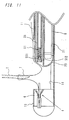
- Fig. 3 is an enlarged section view of a covering member shown in Fig. 1;
- Fig. 4 is an enlarged sectional view of a distal portion of the suture device of Fig. 1, including the first and second suture-holding portion thereof;
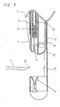
- Fig. 5 is an enlarged sectional view partially taken along a line A-A' in Fig. 1;
- Fig. 6 is a schematic diagram illustrating suture operation using the intracardiac suture device of the present invention;
- Fig. 7 is a schematic diagram illustrating suture operation using the intracardiac suture device of the present invention;
- Fig. 8 is a schematic diagram illustrating suture operation using the intracardiac suture device of the present invention;
- Fig. 9 is a schematic diagram illustrating suture operation using the intracardiac suture device of the present invention;
- Fig. 10 is a schematic diagram illustrating suture operation using the intracardiac suture device of the present invention;
- Fig. 11 is a schematic diagram illustrating suture operation using the intracardiac suture device of the present invention;
- Fig. 12 is a schematic diagram illustrating suture operation using the intracardiac suture device of the present invention;
- Fig. 13 is a schematic diagram illustrating suture operation using the intracardiac suture device of the present invention.
-
- Referring now to Figs. 1 to 5, there is shown an intracardiac suture device according to the present invention, which comprises: a
first shaft assembly 1 comprising afirst shaft 11 and a first suture needle-holding means (or a first suture needle gripper) 4; asecond shaft assembly 2 comprising asecond shaft 21 having first andsecond lumens member 23; athird shaft assembly 3 comprising a hollowthird shaft 31 and ahandling portion 33; and apuncture assembly 5 provided with a second suture needle-holding means 51. The second suture needle-holding means 51 being removably arranged in the distal end of thethird shaft 31; and anendoscope 8; wherein asuture needle 6 is adapted to be transferable between the first suture needle-holding means 4 and the second suture needle-holding means 51 when thethird shaft 31 is slid to the distal end of the coveringmember 23 after sliding of thesecond shaft 21 to a position where a suture site is clamped between the coveringmember 23 and the first suture needle-holding means 4. - As illustrated in Fig. 4, the
first shaft assembly 1 comprises afirst shaft 11 with a lumen 111 extending from a proximal end thereof to a distal end thereof and passing therethrough, a first suture needle-holding means 4 coaxially provided at a distal end of thefirst shaft 11 and spaced therefrom, and afirst connector 12 provided on the proximal end of thefirst shaft 11 and having a hemostatic valve. - The
first shaft 11 is a tubular member made of a metal such as stainless steel and brass, meshed or coiled stainless steel, or a synthetic resin such as fluoroplastic (e.g., polytetrafluoroethylene), polypropylene, polyethylene, polyamide, polyethylene terephthalate, polyurethane and the like. Thfirst shaft 11 has lumen 111, which passes therethrough from the distal end thereof to the proximal end thereof. Thesecond shaft assembly 2 is slidably and rotatably attached to thefirst shaft assembly 1 by inserting thesecond shaft 21 into the lumen 111 of thefirst shaft 11 through theconnector 12 provided on the proximal end of thefirst shaft 11. - The
first connector 12 is a tubular member generally made of a synthetic resin such as polypropylene, ABS (acrylonitrile-butadiene-styrene) resin, polyvinyl chloride, polyethylene and polyethylene terephthalate, or a metal such as stainless steel, brass and the like. Thefirst connector 12 is provided at a proximal end thereof with a through-hole 121 for insertion of thesecond shaft 21. Thefirst connector 12 is provided with a stepped lumen of which a proximal portion has an inner diameter smaller than that of a distal portion thereof. When thesecond shaft assembly 2 is moved toward the proximal end of the device by relative movement, the relative movement of thesecond shaft assembly 2 toward the proximal end of the device is stopped by engagement of anannular rib 213 of thesecond shaft 2 mentioned below with a steppedportion 123 of thefirst connector 12. Thefirst connector 12 is provided in a sidewall thereof with a pair of opposinggrooves 122 into which a pair ofprotrusions 221 of theconnector 22 of thesecond shaft 21 mentioned below. Thus, the relative movement of thesecond shaft 21 toward the distal end of thesecond shaft assembly 2 is stopped when theprotrusions 221 are snugly fitted in thecorresponding grooves 122 of thefirst connector 12. Thefirst connector 12 is also provided in an interior thereof with a hemostatic means (not illustrated in the drawings) for preventing leakage of the blood during operation. - The first suture needle-holding means 4 may be arranged in a needle-holding means
housing 13, which is formed as an integral part of a tube forming thefirst shaft 11. In this embodiment, as illustrated in Fig. 1, the needle-holding meanshousing 13 is provided at the distal end of the tube, which forms thefirst shaft 11. The needle-holding meanshousing 13 is spaced from the distal end of thefirst shaft 11 by anotch 14 formed in the distal end of thefirst shaft 11. Thenotch 14 has a predetermined length and a depth sufficiently greater than a radius of thefirst shaft 11. The needle-holding meanshousing 13 is closed at the distal end thereof by a closingmember 43 to which the first suture needle-holding means 4, is fixed. - The first suture needle-holding means 4 is arranged in the needle-holding means
housing 13 such that the distal end thereof is directed to thefirst shaft 11. The first suture needle-holding means 4 may be comprised of, as illustrated in Fig. 4, a flexible hollow member 41 including a needle-holding portion with an inner diameter slightly smaller than a diameter of thesuture needle 6. The hollow member 41 is provided at a distal end thereof with aneedle guide port 42, and at a proximal side thereof withplural slits 411 extending in the longitudinal direction thereof. - The hollow members 41 of the fist suture needle-holding means 4 may be made of a metal such as stainless steel, brass and the like or a flexible resin such as polypropylene, polyethylene, polyamids and the like. The
needle guide port 42 may be made of a synthetic resin such as fluoroplastic (e.g., polytetrafluoroethylene), polypropylene, polyethylene, polyamide, polyethylene terephthalate, polyurethane and the like. - As can be seen from Figs. 1 and 4, the
second shaft assembly 2 comprises asecond shaft 21 having first andsecond lumens transparent cover member 23 attached to the distal end of thesecond shaft 21 to close the distal end of thesecond lumen 212, and aconnector 22 attached to the proximal end of thesecond shaft 21 and having a hemostatic valve provided therein. Thesecond shaft 21 is movable by sliding movement in the direction of the first suture needle-holding means 4 and is rotatable within thefirst shaft assembly 1. Thefirst lumen 211 houses thepuncture assembly 5 slidably inserted therein, while thesecond lumen 212 houses an endoscope arranged therein. - Any cover member may constitute the
cover member 23 if it can protect the endoscope. A non-limitative preferred cover member is the one having alumen 231 communicated with thefirst lumen 211 at a proximal end thereof and being open at a distal end thereof, and alumen 232 communicated with thesecond lumen 212 at a proximal end thereof and closed at a distal end thereof. Thecover member 23 may be made of a transparent plastic such as, for example, acrylic resin, polystyrene, polypropylene, polymethyl methacrylate, polyamide, polyester, polycarbonate and the like. - The
second shaft 21 is a slender hollow tubular member made of the same material as that used for thefirst shaft 11. Into the first andsecond lumens second shaft 21 from the distal end thereof to the proximal end thereof, the third shaft assembly 3 (actually, thethird shaft 31 through the connector 22) andendoscope 8 are slidably inserted, respectively. - The
second connector 22 is a tubular member made of the same material as that of theconnector 12, and is provided at a proximal end thereof with an insertion hole (not illustrated in the drawings) for thethird shaft 311 andendoscope 8. Theconnector 22 is further provided in its interior with a hemostatic means (not illustrated in the drawings) for preventing the blood from leakage during operation. - The
third shaft assembly 3 comprises a hollowthird shaft 31 and a handlingportion 33 provided at a proximal end of thethird shaft 31. Thethird shaft 31 is a slender tubular member made of the same material as that of thefirst shaft 11 and having alumen 311 passing therethrough from a distal end thereof to a proximal end thereof. Thethird shaft 31 is provided at the proximal end thereof with the handlingportion 33 for actuating it back and forth by sliding movement, through which anoperating rod 52 of an after-mentioned second suture needle-holdingmeans 51 is inserted movably back and forth. There is no limit to a material for the handlingportion 33, but the handlingportion 33 is generally made of the same as that used for thethird shaft 31. - The
puncture assembly 5 is slidably arranged in thethird shaft assembly 3. Thepuncture assembly 5 comprises a second suture needle-holding means 51, and a slenderhollow operating rod 52 connected to a proximal end of the second suture needle-holdingmeans 51. The second suture needle-holdingmeans 51 is positioned in the distal end of thethird shaft 31 and adapted to be put in and out thelumen 311 of thethird shaft 31. The operatingrod 52 is movably arranged in thelumen 311 of thethird shaft 31. - The second suture needle-holding
means 51 comprises a flexiblehollow member 55 having an inner diameter slightly larger than the diameter of thesuture needle 6 and an outer diameter smaller than the inner diameter of thethird shaft 31. Thehollow member 55 is provided at the distal end thereof with aenlarged head portion 552, which has an outer diameter greater than the inner diameter of thethird shaft 31 and is tapered toward the proximal end thereof. Thehollow member 55 is provided withplural slits 551 longitudinally extending from the distal end of thehead portion 552 towards the proximal end ofhollow member 55. - The
hollow operating rod 52 slidably arranged in thelumen 311 of thethird shaft 31 is connected to the proximal end of thehollow member 55. Theenlarged head portion 552 is adapted to hold thesuture needle 6 therein by reduction of the inner diameter thereof when theenlarged head portion 552 is housed in thethird shaft 31. In this case, as illustrated in Figs. 6 and 7, thethird shaft 31 is preferably provided with an annular rib 312 at the distal portion of thelumen 311 thereof to prevent theenlarged head portion 552 from movement toward the proximal side thereof at the time of seating of theenlarged head portion 552 in thethird shaft 31. - When the
enlarged head portion 552 is pushed out of the lumen of thethird shaft 31, theenlarged head portion 552 may be returned to the lumen of thethird shaft 31 by manually operating the operatingrod 52. Alternately, as illustrated in Fig. 4, theenlarged head portion 552 may be returned automatically to its original position by providing an auto-return mechanism, which comprises, for example, aflange 553 provided at the proximal end of thehollow member 55, and acoil spring 53 arranged around thehollow member 55 and between theflange 553 and the annular rib 312 so that thecoil spring 53 is compressed when the operatingrod 52 is pushed forward in thethird shaft 31, and then restored by the restoring force of thecoil spring 53 to automatically house theenlarged head portion 552 to thelumen 311 of thethird shaft 31. - Further, in order to improve the operationality of the second suture needle-holding means 51, the operating
rod 52 may be provided at a proximal end thereof with a handlingportion 54, which is adapted to be moved forward and backward with respect to the handlingportion 33 of thethird shaft assembly 3. - In a suture set comprised of the aforesaid first, second and
third shafts assembly puncture member 5 andendoscope 8, thesuture needle 6 is transferred between the first suture needle-holding means 4 and the second suture needle-holding means 51 when thethird shaft 31 is moved to the distal end of thesecond shaft 21 that had been moved beyond the distal end of thefirst shaft 1 to a position where a suture site is held between thesecond shaft 21 and the first suture needle-holding means 4. - If necessary, the
first connector 12 and/orsecond connector 22 may be provided with a side tube 222 for infusion of heparin, saline for irrigation and the like. - The
hollow member 55 of the second suture needle-holding means 51 may be made of, without being limited to, the same materials as those used for the hollow member 41 of the first suture needle-holding means 4 as thehollow member 55 has the same structure and function as those of the hollow member 41 of the first suture needle-holding means 4. - Using the intracardiac suture device of the present invention, closure of defects may be carried out in the manner mentioned below with reference to Figs. 6 to 13.
- Firstly, the heart is exposed by surgical incision of the chest of a patient to check the position of the heart and then punctured at an appropriate part of the heart (usually, the right auricle). A sheath (not illustrated in the drawings) for insertion of an intracardiac suture device is inserted into the heart through the punctured part thereof until a leading end of the sheath reaches to a position near a suture site. Then, the intracardiac suture device illustrated in Figs. 1 and 2 is inserted into the sheath and guided to the position near the suture site. In that case, the
third shaft 31 and the second suture needle-holding means 51of the suture device have been set so as to have a physical relationship as illustrated in Fig. 4. - As illustrated in Fig. 6, the distal end of the suture device is protruded from the sheath to locate the first suture needle-holding means 4 within a defect aperture DA of the heart so that the
notch 14 is located in the defect aperture DA. Thesecond shaft assembly 2 is then pushed manually toward thefirst shaft assembly 1 to hold a tissue T surrounding the defect aperture DA between the distal end of thesecond shaft 21 and the needle-holding meanshousing 13, while checking out the physical relationship between the device and the suture site in the heart with theendoscope 8. At that time, thethird shaft assembly 3 is moved forward along with the second shaft assembly 2 (Fig. 7). Under the condition of the tissue T that has been held between the needle-holding meanshousing 13 and thesecond shaft 21, thethird shaft assembly 3 is pushed toward thesecond shaft assembly 2 by operating thefirst handling portion 33, with the result that the second puncture needle-holding means 51 housed in thethird shaft 31 is moved forward along with thethird shaft 31 to puncture the tissue T. Thus, the distal portion of thepuncture needle 6 is inserted into the first suture needle-holding means 4 and gripped therein at the distal end thereof (Fig. 8). At that time, it is possible to observe the condition of thesuture needle 6 that punctured the tissue T. - When the handling
portion 33 is moved to a position adjacent to the handling portion 54 (an adjacent condition) by holding the handlingportion third shaft assembly 3 is backed toward thepuncture assembly 5 since thepuncture assembly 5 is locked to the first suture needle-holding means 4 by thesuture needle 6. At that time, theenlarged head portion 552 is unsheathed from thethird shaft 31 and thus thehollow member 55 is released from the compression pressure of thethird shaft 31. For this reason, thehollow member 55 is returned to the uncompressed condition where the inner diameter of thehollow member 55 is larger than the outer diameter of thesuture needle 6, and thesuture needle 6 is released from the second suture needle-holding means 51 (cf. Fig. 9). At the same time, thecoil spring 53 is compressed by the backward movement of the handlingportion 33. Under that condition, thefirst shaft assembly 1 is manually pushed forward over thesecond shaft assembly 2 as it stands, with the result that thesuture needle 6 is passed through the tissue T and transferred to the first suture needle-holding means 4 on the opposite side of the second suture needle-holding means 51 with respect to the tissue T, as illustrated in Fig. 10. - Then, the whole suture device is somewhat moved backward and the handling
portion 54 of thepuncture assembly 5 is released from the hand while holding the handlingportion 33 by hand, so that the second suture needle holding means 51 is moved backward by the restoring force of thecoil spring 53. Thus, theenlarged head portion 552 is pulled in thelumen 311 of thethird shaft 31. At that time, the handlingportions portion 14, as illustrated in Fig. 11. In this connection, it is possible to observe the conditions of theneedle 6 held by the first needle-holding means 4 by rotating thesecond shaft assembly 2 about thefirst shaft assembly 1 to coincide the center of the endoscope with the center of theneedle guide port 42. - Next, the
second shaft assembly 2 is pushed forward so that it take the position approximately the same position illustrated in Fig. 7. Then, the handlingportion 54 of thepuncture assembly 5 is moved to a position closed to the handlingportion 33 while holding the operatingportions enlarged head portion 552 of the second needle-holdingmeans 51 is unsheathed from thethird shaft 31 and thehollow member 55 is released from the compression pressure of thethird shaft 31. Thus, thehollow member 55 is returned to the uncompressed condition where the inner diameter of thehollow member 55 is larger than the outer diameter of thesuture needle 6. At that time, thecoil spring 53 is being compressed. Under such conditions, thethird shaft assembly 3 is advanced in connection with thesecond shaft assembly 2 by pushing the handlingportion 33, so that thesuture needle 6 is received by the second suture needle-holding means 51 as illustrated in Fig. 12. - Then, by taking off the handling
portion 33 while holding thesecond shaft assembly 2 and the handlingportion 54 of thepuncture assembly 5, thethird shaft assembly 3 is moved forward by the restoring force of thecoil spring 53. For this reason, theenlarged head portion 552 is received in thethird shaft 31 and thehollow member 55 is compressed by thethird shaft 31 to make the inner diameter of thehollow member 55 smaller than the outer diameter of thesuture needle 6. And thus, thesuture needle 6 is held by the suture needle-holdingmeans 51. Under such conditions, thefirst shaft assembly 1 is pushed forward manually in connection with thesecond shaft assembly 2, thesuture needle 6 is transferred to the second suture needle-holdingmeans 51 and brought to the condition as illustrated in Fig. 13. - The closure of defect is completed by repeating the above procedures several times, and carrying out ligature and cutting of the suture with a special purpose device.
- As will be understood from the above description, the use of the intracardiac suture device of the present invention makes it possible to perform a minimally invasive operation for suturing intracardiac defects without use of any artificial heart-lung system.
- Further, the present invention makes it possible to perform intracardiac operations certainly and safely at a lower cost as compared with the conventional operations using any artificial heart-lung system. In addition, the present invention makes it possible to minimize risk of complications after the operation since the recovery time after operation is reduced to about one day, which is very short as compared with the recovery time of more than one week. Also, the present device is easy to operate and contribute to reduce burdens for an operator.
wherein said second shaft is protrusible by sliding-movement from the distal end of the first shaft toward the first suture needle-holding means, and wherein a suture needle is transferable between the first suture needle-holding means and the second suture needle-holding means when the third shaft is slid to the distal end of the second shaft after sliding the second shaft to a position where a suture site is held between said covering member and the first suture needle-holding means.
Claims (5)
- An intracardiac suture device, comprising:wherein said second shaft is protrusible by sliding-movement from the distal end of the first shaft toward the first suture needle-holding means, and wherein a suture needle is transferable between the first suture needle-holding means and the second suture needle-holding means when the third shaft is slid to the distal end of the second shaft after sliding the second shaft to a position where a suture site is held between said covering member and the first suture needle-holding means.a first shaft assembly comprising a first shaft having a lumen passing therethrough from a proximal end to a distal end thereof, a first suture needle-holding means coaxially provided at and spaced from the distal end of the first shaft, and a connector with a hemostatic valve provided on the proximal end of the first shaft;a second shaft assembly comprising a second shaft slidably arranged in the first shaft assembly, and a connector with a hemostatic valve provided on the proximal end of the second shaft, said second shaft having first and second lumens passing therethrough from a proximal end thereof to a distal end thereof, said second lumen being closed at a distal end thereof with a transparent covering member;a third shaft assembly comprising a hollow third shaft slidably arranged in the first lumen of said second shaft assembly, and a handling portion provided at a proximal end of the third shaft; anda puncture assembly comprising a hollow operating rod provided at a distal end thereof with a second suture needle-holding means movably arranged in the distal end of the third shaft, said hollow operating rod being connected to the proximal end of the second suture needle-holding means and movably arranged in the third shaft assembly;and a visual monitoring means arranged in the distal end of the second lumen at a position close to the distal end of said cover member;
- The intracardiac suture device according to claim 1, wherein the second shaft assembly is rotatable in the first shaft assembly.
- The intracardiac suture device according to claim 1 or claim 2, wherein said visual monitoring means is an endoscope or ultrasonic transducer.
- The intracardiac suture device according to claim 1, 2 or 3, wherein the second connector is provided with a pair of rotationally symmetrical protrusion extending from the peripheral portion toward the distal end thereof, and wherein said first connector is provided on its proximal end side with a pair of recesses for receiving said protrusions, and wherein said second shaft is movable between a position where the protrusions are respectively received in said recesses and a position where the protrusions are disengaged from said recesses.
- The intracardiac suture device according to any of claims 1 to 4, wherein either or both connectors of the first and second shaft assemblies may be provided with a side tube for infusion of heparin, a saline solution or the like.
Applications Claiming Priority (2)
| Application Number | Priority Date | Filing Date | Title |
|---|---|---|---|
| JP2002112183A JP3890589B2 (en) | 2002-04-15 | 2002-04-15 | Intracardiac suture device |
| JP2002112183 | 2002-04-15 |
Publications (3)
| Publication Number | Publication Date |
|---|---|
| EP1354558A2 true EP1354558A2 (en) | 2003-10-22 |
| EP1354558A3 EP1354558A3 (en) | 2003-12-10 |
| EP1354558B1 EP1354558B1 (en) | 2006-12-06 |
Family
ID=28672574
Family Applications (1)
| Application Number | Title | Priority Date | Filing Date |
|---|---|---|---|
| EP03008029A Expired - Lifetime EP1354558B1 (en) | 2002-04-15 | 2003-04-11 | Intracardiac suture device |
Country Status (5)
| Country | Link |
|---|---|
| US (1) | US7063710B2 (en) |
| EP (1) | EP1354558B1 (en) |
| JP (1) | JP3890589B2 (en) |
| AT (1) | ATE347315T1 (en) |
| DE (1) | DE60310154T2 (en) |
Cited By (8)
| Publication number | Priority date | Publication date | Assignee | Title |
|---|---|---|---|---|
| WO2005070305A1 (en) | 2004-01-14 | 2005-08-04 | Lsi Solutions, Inc. | Running stitch suturing device |
| WO2010085793A3 (en) * | 2009-01-26 | 2010-09-10 | Synthes Usa, Llc | Bi-directional suture passer |
| EP2314227A1 (en) * | 2009-10-01 | 2011-04-27 | Tyco Healthcare Group LP | Wound closure device including direct-driven needle |
| US8906042B2 (en) | 2010-07-29 | 2014-12-09 | Covidien Lp | Wound closure device including mesh barrier |
| US9155533B2 (en) | 2010-05-06 | 2015-10-13 | DePuy Synthes Products, Inc. | Soft tissue defect device and associated method |
| WO2018156603A1 (en) * | 2017-02-22 | 2018-08-30 | Boston Scientific Scimed, Inc. | Suture based closure device |
| US11896214B2 (en) | 2020-03-31 | 2024-02-13 | Boston Scientific Scimed, Inc. | Suture based closure device |
| US11918202B2 (en) | 2019-05-16 | 2024-03-05 | Boston Scientific Scimed, Inc. | Suture based closure device for use with endoscope |
Families Citing this family (132)
| Publication number | Priority date | Publication date | Assignee | Title |
|---|---|---|---|---|
| US20040092964A1 (en) | 1999-03-04 | 2004-05-13 | Modesitt D. Bruce | Articulating suturing device and method |
| US8137364B2 (en) | 2003-09-11 | 2012-03-20 | Abbott Laboratories | Articulating suturing device and method |
| US7842048B2 (en) | 2006-08-18 | 2010-11-30 | Abbott Laboratories | Articulating suture device and method |
| US7001400B1 (en) | 1999-03-04 | 2006-02-21 | Abbott Laboratories | Articulating suturing device and method |
| US7235087B2 (en) | 1999-03-04 | 2007-06-26 | Abbott Park | Articulating suturing device and method |
| US6964668B2 (en) | 1999-03-04 | 2005-11-15 | Abbott Laboratories | Articulating suturing device and method |
| US7083628B2 (en) * | 2002-09-03 | 2006-08-01 | Edwards Lifesciences Corporation | Single catheter mitral valve repair device and method for use |
| ES2435094T3 (en) | 2000-05-19 | 2013-12-18 | C.R. Bard, Inc. | Device and method of tissue capture and suturing |
| US7160309B2 (en) | 2002-12-31 | 2007-01-09 | Laveille Kao Voss | Systems for anchoring a medical device in a body lumen |
| JP4565218B2 (en) * | 2003-05-16 | 2010-10-20 | シー・アール・バード・インク | Single intubation multiple-time suture endoscopic suture system |
| US7462188B2 (en) | 2003-09-26 | 2008-12-09 | Abbott Laboratories | Device and method for suturing intracardiac defects |
| US20060276684A1 (en) * | 2003-11-07 | 2006-12-07 | Giovanni Speziali | Device and method for treating congestive heart failure |
| US7449024B2 (en) | 2003-12-23 | 2008-11-11 | Abbott Laboratories | Suturing device with split arm and method of suturing tissue |
| EP1702569B1 (en) * | 2004-01-08 | 2015-10-14 | Olympus Corporation | Anastomosis device and method of excising wall portion of in vivo luminal organ |
| US7211093B2 (en) * | 2004-01-14 | 2007-05-01 | Lsi Solutions, Inc. | Sew-right running stitch instrument |
| US7232448B2 (en) * | 2004-06-17 | 2007-06-19 | Ethicon, Inc. - Usa | Minimally invasive stitching device |
| US8172857B2 (en) * | 2004-08-27 | 2012-05-08 | Davol, Inc. | Endoscopic tissue apposition device and method of use |
| DE102004041936B3 (en) * | 2004-08-30 | 2005-10-06 | Medi-Globe Gmbh | A surgical device for passing at least two sutures through the edge region of a tissue opening |
| US20060135970A1 (en) * | 2004-11-15 | 2006-06-22 | Laurent Schaller | Catheter-based tissue remodeling devices and methods |
| EP1845861B1 (en) | 2005-01-21 | 2011-06-22 | Mayo Foundation for Medical Education and Research | Thorascopic heart valve repair apparatus |
| EP1859743B1 (en) | 2005-03-17 | 2015-08-05 | Olympus Corporation | Suture instrument |
| US8333777B2 (en) | 2005-04-22 | 2012-12-18 | Benvenue Medical, Inc. | Catheter-based tissue remodeling devices and methods |
| EP1909655A2 (en) | 2005-06-20 | 2008-04-16 | Sutura, Inc. | Method and apparatus for applying a knot to a suture |
| US20060293699A1 (en) * | 2005-06-28 | 2006-12-28 | Boston Scientific Scimed, Inc | Low profile suturing instrument |
| US8267947B2 (en) | 2005-08-08 | 2012-09-18 | Abbott Laboratories | Vascular suturing device |
| US7883517B2 (en) | 2005-08-08 | 2011-02-08 | Abbott Laboratories | Vascular suturing device |
| US8083754B2 (en) | 2005-08-08 | 2011-12-27 | Abbott Laboratories | Vascular suturing device with needle capture |
| US20070060895A1 (en) | 2005-08-24 | 2007-03-15 | Sibbitt Wilmer L Jr | Vascular closure methods and apparatuses |
| US9456811B2 (en) | 2005-08-24 | 2016-10-04 | Abbott Vascular Inc. | Vascular closure methods and apparatuses |
| US8920442B2 (en) | 2005-08-24 | 2014-12-30 | Abbott Vascular Inc. | Vascular opening edge eversion methods and apparatuses |
| US8894661B2 (en) | 2007-08-16 | 2014-11-25 | Smith & Nephew, Inc. | Helicoil interference fixation system for attaching a graft ligament to a bone |
| EP2051640B1 (en) * | 2006-08-16 | 2010-01-20 | Wilson-Cook Medical Inc. | Suturing device |
| EP2081481B1 (en) | 2006-10-05 | 2015-03-11 | Covidien LP | Flexible endoscopic stitching devices |
| EP2083702B1 (en) | 2006-10-05 | 2019-02-13 | Covidien LP | Axial stitching device |
| US8574244B2 (en) | 2007-06-25 | 2013-11-05 | Abbott Laboratories | System for closing a puncture in a vessel wall |
| US8702731B2 (en) | 2007-07-03 | 2014-04-22 | Ceterix Orthopaedics, Inc. | Suturing and repairing tissue using in vivo suture loading |
| US10441273B2 (en) | 2007-07-03 | 2019-10-15 | Ceterix Orthopaedics, Inc. | Pre-tied surgical knots for use with suture passers |
| US20090012538A1 (en) * | 2007-07-03 | 2009-01-08 | Justin Saliman | Methods and devices for continuous suture passing |
| US20110130773A1 (en) * | 2007-07-03 | 2011-06-02 | Saliman Justin D | Methods for continuous suture passing |
| US8821518B2 (en) | 2007-11-05 | 2014-09-02 | Ceterix Orthopaedics, Inc. | Suture passing instrument and method |
| US9211119B2 (en) | 2007-07-03 | 2015-12-15 | Ceterix Orthopaedics, Inc. | Suture passers and methods of passing suture |
| US8663253B2 (en) | 2007-07-03 | 2014-03-04 | Ceterix Orthopaedics, Inc. | Methods of meniscus repair |
| US9314234B2 (en) | 2007-07-03 | 2016-04-19 | Ceterix Orthopaedics, Inc. | Pre-tied surgical knots for use with suture passers |
| US8911456B2 (en) | 2007-07-03 | 2014-12-16 | Ceterix Orthopaedics, Inc. | Methods and devices for preventing tissue bridging while suturing |
| US9861354B2 (en) | 2011-05-06 | 2018-01-09 | Ceterix Orthopaedics, Inc. | Meniscus repair |
| US20100130990A1 (en) * | 2007-07-03 | 2010-05-27 | Saliman Justin D | Methods of suturing and repairing tissue using a continuous suture passer device |
| US8465505B2 (en) | 2011-05-06 | 2013-06-18 | Ceterix Orthopaedics, Inc. | Suture passer devices and methods |
| US8500809B2 (en) | 2011-01-10 | 2013-08-06 | Ceterix Orthopaedics, Inc. | Implant and method for repair of the anterior cruciate ligament |
| CA2703129C (en) | 2007-10-18 | 2016-02-16 | Neochord Inc. | Minimially invasive repair of a valve leaflet in a beating heart |
| EP2230987B1 (en) * | 2008-01-03 | 2013-02-27 | Cook Medical Technologies LLC | Medical systems for endoscopically suturing perforations |
| BRPI0820149B8 (en) * | 2008-02-28 | 2021-06-22 | Tag Medical Devices Agriculture Coop Ltd | medical instrument to drill a hole in a bone and medical instrument kit to drill a hole in a bone |
| US8864776B2 (en) | 2008-04-11 | 2014-10-21 | Covidien Lp | Deployment system for surgical suture |
| US8628545B2 (en) | 2008-06-13 | 2014-01-14 | Covidien Lp | Endoscopic stitching devices |
| US20110040308A1 (en) | 2008-06-13 | 2011-02-17 | Ramiro Cabrera | Endoscopic Stitching Devices |
| US11083364B2 (en) | 2008-06-17 | 2021-08-10 | Apollo Endosurgery Us, Inc. | Endoscopic tissue grasping systems and methods |
| US11812951B2 (en) | 2008-06-17 | 2023-11-14 | Apollo Endosurgery Us, Inc. | Endoscopic needle assembly |
| US8287556B2 (en) * | 2008-06-17 | 2012-10-16 | Apollo Endosurgery, Inc. | Endoscopic suturing system |
| US9198562B2 (en) | 2008-06-17 | 2015-12-01 | Apollo Endosurgery, Inc. | Endoscopic needle assembly |
| US8863748B2 (en) * | 2008-07-31 | 2014-10-21 | Olympus Medical Systems Corp. | Endoscopic surgical operation method |
| CA2738426C (en) | 2008-09-29 | 2016-03-15 | C.R. Bard, Inc. | Endoscopic suturing device |
| US9943306B2 (en) | 2009-04-14 | 2018-04-17 | Covidien Lp | Knotless endostitch suture retainer |
| EP2429374B1 (en) * | 2009-05-01 | 2013-09-25 | Cook Medical Technologies LLC | Medical device for suturing perforations |
| USD708746S1 (en) | 2009-06-10 | 2014-07-08 | Covidien Lp | Handle for surgical device |
| US8490713B2 (en) | 2009-10-06 | 2013-07-23 | Covidien Lp | Handle assembly for endoscopic suturing device |
| US9011454B2 (en) | 2009-11-09 | 2015-04-21 | Ceterix Orthopaedics, Inc. | Suture passer with radiused upper jaw |
| US9848868B2 (en) | 2011-01-10 | 2017-12-26 | Ceterix Orthopaedics, Inc. | Suture methods for forming locking loops stitches |
| US11744575B2 (en) | 2009-11-09 | 2023-09-05 | Ceterix Orthopaedics, Inc. | Suture passer devices and methods |
| WO2011057245A2 (en) | 2009-11-09 | 2011-05-12 | Suturepro Technologies, Inc. | Devices, systems and methods for meniscus repair |
| US9775702B2 (en) | 2010-03-10 | 2017-10-03 | Smith & Nephew, Inc. | Composite interference screws and drivers |
| US9579188B2 (en) | 2010-03-10 | 2017-02-28 | Smith & Nephew, Inc. | Anchor having a controlled driver orientation |
| US9308080B2 (en) | 2010-03-10 | 2016-04-12 | Smith & Nephew Inc. | Composite interference screws and drivers |
| US9370353B2 (en) | 2010-09-01 | 2016-06-21 | Abbott Cardiovascular Systems, Inc. | Suturing devices and methods |
| US8663252B2 (en) | 2010-09-01 | 2014-03-04 | Abbott Cardiovascular Systems, Inc. | Suturing devices and methods |
| US9161751B2 (en) * | 2010-12-02 | 2015-10-20 | Coloplast A/S | Suture system and assembly |
| WO2012141757A1 (en) | 2010-12-29 | 2012-10-18 | Neochord, Inc. | Exchangeable system for minimally invasive beating heart repair of heart valve leaflets |
| US8568428B2 (en) | 2011-01-05 | 2013-10-29 | Coloplast A/S | Suture system and assembly including a tubular leader having a clasp |
| US9913638B2 (en) | 2011-01-10 | 2018-03-13 | Ceterix Orthopaedics, Inc. | Transosteal anchoring methods for tissue repair |
| US20120197270A1 (en) * | 2011-01-28 | 2012-08-02 | Coloplast A/S | Suture system and assembly including a leader plug |
| US8864777B2 (en) | 2011-01-28 | 2014-10-21 | Anchor Orthopedics Xt Inc. | Methods for facilitating tissue puncture |
| US9220495B2 (en) * | 2011-02-10 | 2015-12-29 | Coloplast A/S | Suture system and assembly including a suture clip |
| US8968340B2 (en) | 2011-02-23 | 2015-03-03 | Covidien Lp | Single actuating jaw flexible endolumenal stitching device |
| US8591528B2 (en) * | 2011-02-24 | 2013-11-26 | Coloplast A/S | Suture system and assembly including a suture cap formed around a tubular sleeve |
| MX344606B (en) | 2011-03-11 | 2016-12-20 | Smith & Nephew Inc | Trephine. |
| AU2012261998B2 (en) | 2011-06-01 | 2017-03-02 | Neochord, Inc. | Minimally invasive repair of heart valve leaflets |
| MX2013014423A (en) | 2011-06-07 | 2014-05-28 | Smith & Nephew Inc | Surgical anchor delivery system. |
| JP6174025B2 (en) | 2011-08-18 | 2017-08-02 | アンカー オーソペディックス エックスティー インコーポレイテッドAnchor Orthopedics Xt Inc. | Bi-directional suture threader |
| US10537321B2 (en) | 2014-04-08 | 2020-01-21 | Ceterix Orthopaedics, Inc. | Suture passers adapted for use in constrained regions |
| US9492162B2 (en) | 2013-12-16 | 2016-11-15 | Ceterix Orthopaedics, Inc. | Automatically reloading suture passer devices and methods |
| US10524778B2 (en) | 2011-09-28 | 2020-01-07 | Ceterix Orthopaedics | Suture passers adapted for use in constrained regions |
| US8858573B2 (en) | 2012-04-10 | 2014-10-14 | Abbott Cardiovascular Systems, Inc. | Apparatus and method for suturing body lumens |
| US8864778B2 (en) | 2012-04-10 | 2014-10-21 | Abbott Cardiovascular Systems, Inc. | Apparatus and method for suturing body lumens |
| US9241707B2 (en) | 2012-05-31 | 2016-01-26 | Abbott Cardiovascular Systems, Inc. | Systems, methods, and devices for closing holes in body lumens |
| JP6430415B2 (en) * | 2013-03-06 | 2018-11-28 | スミス アンド ネフュー インコーポレーテッドSmith & Nephew,Inc. | Compound tightening screw and screwdriver |
| US9155531B2 (en) | 2013-03-15 | 2015-10-13 | Smith & Nephew, Inc. | Miniaturized dual drive open architecture suture anchor |
| US9579098B2 (en) | 2013-03-15 | 2017-02-28 | King Saud University | Bendable suture needle with free varying angle and holder therefor |
| AU2014251015B2 (en) | 2013-04-09 | 2019-01-17 | Smith & Nephew, Inc. | Open-architecture interference screw |
| US9247935B2 (en) | 2013-09-23 | 2016-02-02 | Ceterix Orthopaedics, Inc. | Arthroscopic knot pusher and suture cutter |
| WO2015085145A1 (en) | 2013-12-06 | 2015-06-11 | Med-Venture Investments, Llc | Suturing methods and apparatuses |
| US9468434B2 (en) | 2014-06-03 | 2016-10-18 | Covidien Lp | Stitching end effector |
| US10092286B2 (en) | 2015-05-27 | 2018-10-09 | Covidien Lp | Suturing loading unit |
| US10226245B2 (en) | 2015-07-21 | 2019-03-12 | Ceterix Orthopaedics, Inc. | Automatically reloading suture passer devices that prevent entanglement |
| WO2017059406A1 (en) | 2015-10-01 | 2017-04-06 | Neochord, Inc. | Ringless web for repair of heart valves |
| US10405853B2 (en) | 2015-10-02 | 2019-09-10 | Ceterix Orthpaedics, Inc. | Knot tying accessory |
| BR112018009759A2 (en) * | 2015-11-12 | 2018-12-04 | Surgimatix Inc | laparoscopic suture with extraction plate |
| KR101711305B1 (en) * | 2015-12-28 | 2017-03-06 | 한국기술교육대학교 산학협력단 | Suturing device |
| US9861410B2 (en) | 2016-05-06 | 2018-01-09 | Medos International Sarl | Methods, devices, and systems for blood flow |
| US10542970B2 (en) | 2016-05-31 | 2020-01-28 | Covidien Lp | Endoscopic stitching device |
| US11051800B2 (en) | 2016-08-10 | 2021-07-06 | Apollo Endosurgery Us, Inc. | Endoscopic suturing system having external instrument channel |
| US11141147B2 (en) | 2016-08-10 | 2021-10-12 | Apollo Endosurgery Us, Inc. | Endoscopic suturing system having external instrument channel |
| US10426449B2 (en) * | 2017-02-16 | 2019-10-01 | Abbott Cardiovascular Systems, Inc. | Articulating suturing device with improved actuation and alignment mechanisms |
| US10898181B2 (en) | 2017-03-17 | 2021-01-26 | Cypris Medical, Inc. | Suturing system |
| US10213306B2 (en) | 2017-03-31 | 2019-02-26 | Neochord, Inc. | Minimally invasive heart valve repair in a beating heart |
| US11648003B2 (en) * | 2017-05-30 | 2023-05-16 | Suture Ease, Inc. | Biological tissue access and closure apparatus, systems and methods |
| US11154294B2 (en) * | 2018-05-29 | 2021-10-26 | Suture Ease, Inc. | Biological tissue access and closure apparatus, systems and methods |
| US10702263B2 (en) * | 2017-05-30 | 2020-07-07 | Suture Ease, Inc. | Biological tissue access and closure apparatus, systems and methods |
| US11591554B2 (en) | 2017-09-11 | 2023-02-28 | Heartstitch, Inc. | Methods and devices for papillary suturing |
| CA3094990C (en) | 2018-03-23 | 2023-01-03 | Neochord, Inc. | Device for suture attachment for minimally invasive heart valve repair |
| US10660637B2 (en) | 2018-04-06 | 2020-05-26 | Cypris Medical, Inc. | Suturing system |
| US11253360B2 (en) | 2018-05-09 | 2022-02-22 | Neochord, Inc. | Low profile tissue anchor for minimally invasive heart valve repair |
| US11173030B2 (en) | 2018-05-09 | 2021-11-16 | Neochord, Inc. | Suture length adjustment for minimally invasive heart valve repair |
| EP3801294A1 (en) | 2018-05-25 | 2021-04-14 | Boston Scientific Scimed Inc. | Device and method for applying a cinch to a suture |
| US11033261B2 (en) | 2018-05-31 | 2021-06-15 | Cypris Medical, Inc. | Suture system |
| US11399821B2 (en) | 2018-06-19 | 2022-08-02 | Boston Scientific Scimed Inc. | Control handle for endoscopic suturing |
| CN112638284A (en) | 2018-06-27 | 2021-04-09 | 波士顿科学国际有限公司 | Endoscopic attachment mechanism for use with suture-based closure device |
| US11197665B2 (en) | 2018-08-06 | 2021-12-14 | Covidien Lp | Needle reload device for use with endostitch device |
| JP7374997B2 (en) | 2018-09-06 | 2023-11-07 | ボストン サイエンティフィック サイムド,インコーポレイテッド | Suture needle device and suture thread attachment method |
| JP7300198B2 (en) | 2018-09-07 | 2023-06-29 | ネオコード インコーポレイテッド | Suture Attachment Device for Minimally Invasive Heart Valve Repair |
| EP3920770A4 (en) * | 2019-02-08 | 2022-11-02 | Children's Medical Center Corporation | Optical delivery and insertion of artificial chordae tendineae |
| WO2020214818A1 (en) | 2019-04-16 | 2020-10-22 | Neochord, Inc. | Transverse helical cardiac anchor for minimally invasive heart valve repair |
| JP2023514595A (en) | 2020-02-18 | 2023-04-06 | ボストン サイエンティフィック サイムド,インコーポレイテッド | Suture-based closure device for use with an endoscope |
| US11744609B2 (en) | 2020-02-19 | 2023-09-05 | Boston Scientific Scimed, Inc. | High power atherectomy with multiple safety limits |
| CN114081592B (en) * | 2021-11-15 | 2023-11-21 | 北京天助畅运医疗技术股份有限公司 | Puncture device |
Citations (4)
| Publication number | Priority date | Publication date | Assignee | Title |
|---|---|---|---|---|
| US5080663A (en) * | 1990-09-26 | 1992-01-14 | Univerity College London | Sewing device |
| US5792153A (en) * | 1994-03-23 | 1998-08-11 | University College London | Sewing device |
| US6280460B1 (en) * | 1998-02-13 | 2001-08-28 | Heartport, Inc. | Devices and methods for performing vascular anastomosis |
| EP1297787A1 (en) * | 2001-10-01 | 2003-04-02 | Nipro Corporation | Intracardiac suture device |
Family Cites Families (4)
| Publication number | Priority date | Publication date | Assignee | Title |
|---|---|---|---|---|
| GB8422863D0 (en) * | 1984-09-11 | 1984-10-17 | Univ London | Sewing machine |
| US5037433A (en) * | 1990-05-17 | 1991-08-06 | Wilk Peter J | Endoscopic suturing device and related method and suture |
| JP3293118B2 (en) * | 1995-10-18 | 2002-06-17 | ニプロ株式会社 | Catheter assembly for endocardial suture surgery |
| US5766183A (en) * | 1996-10-21 | 1998-06-16 | Lasersurge, Inc. | Vascular hole closure |
-
2002
- 2002-04-15 JP JP2002112183A patent/JP3890589B2/en not_active Expired - Fee Related
-
2003
- 2003-04-11 AT AT03008029T patent/ATE347315T1/en not_active IP Right Cessation
- 2003-04-11 EP EP03008029A patent/EP1354558B1/en not_active Expired - Lifetime
- 2003-04-11 DE DE60310154T patent/DE60310154T2/en not_active Expired - Lifetime
- 2003-04-15 US US10/413,524 patent/US7063710B2/en not_active Expired - Fee Related
Patent Citations (4)
| Publication number | Priority date | Publication date | Assignee | Title |
|---|---|---|---|---|
| US5080663A (en) * | 1990-09-26 | 1992-01-14 | Univerity College London | Sewing device |
| US5792153A (en) * | 1994-03-23 | 1998-08-11 | University College London | Sewing device |
| US6280460B1 (en) * | 1998-02-13 | 2001-08-28 | Heartport, Inc. | Devices and methods for performing vascular anastomosis |
| EP1297787A1 (en) * | 2001-10-01 | 2003-04-02 | Nipro Corporation | Intracardiac suture device |
Cited By (20)
| Publication number | Priority date | Publication date | Assignee | Title |
|---|---|---|---|---|
| EP1703846A1 (en) * | 2004-01-14 | 2006-09-27 | LSI Solutions, Inc. | Running stitch suturing device |
| EP1703846A4 (en) * | 2004-01-14 | 2008-06-18 | Lsi Solutions Inc | Running stitch suturing device |
| WO2005070305A1 (en) | 2004-01-14 | 2005-08-04 | Lsi Solutions, Inc. | Running stitch suturing device |
| US9011466B2 (en) | 2009-01-26 | 2015-04-21 | DePuy Synthes Products, Inc. | Bi-directional suture passer |
| WO2010085793A3 (en) * | 2009-01-26 | 2010-09-10 | Synthes Usa, Llc | Bi-directional suture passer |
| CN102292033A (en) * | 2009-01-26 | 2011-12-21 | 斯恩蒂斯有限公司 | Bi-directional suture passer |
| US9386980B2 (en) | 2009-10-01 | 2016-07-12 | Covidien Lp | Wound closure device including direct-driven needle |
| US10631855B2 (en) | 2009-10-01 | 2020-04-28 | Covidien Lp | Wound closure device including direct-driven needle |
| US8591529B2 (en) | 2009-10-01 | 2013-11-26 | Covidien Lp | Wound closure device including direct-driven needle |
| EP2314227A1 (en) * | 2009-10-01 | 2011-04-27 | Tyco Healthcare Group LP | Wound closure device including direct-driven needle |
| US9980721B2 (en) | 2009-10-01 | 2018-05-29 | Covidien Lp | Wound closure device including direct-driven needle |
| US9155533B2 (en) | 2010-05-06 | 2015-10-13 | DePuy Synthes Products, Inc. | Soft tissue defect device and associated method |
| US9687226B2 (en) | 2010-07-29 | 2017-06-27 | Covidien Lp | Wound closure device including mesh barrier |
| US8906042B2 (en) | 2010-07-29 | 2014-12-09 | Covidien Lp | Wound closure device including mesh barrier |
| WO2018156603A1 (en) * | 2017-02-22 | 2018-08-30 | Boston Scientific Scimed, Inc. | Suture based closure device |
| AU2018225560B2 (en) * | 2017-02-22 | 2020-05-14 | Boston Scientific Scimed, Inc. | Suture based closure device |
| US10932771B2 (en) | 2017-02-22 | 2021-03-02 | Boston Scientific Scimed, Inc. | Suture based closure device |
| US11832809B2 (en) | 2017-02-22 | 2023-12-05 | Boston Scientific Scimed, Inc. | Suture based closure device |
| US11918202B2 (en) | 2019-05-16 | 2024-03-05 | Boston Scientific Scimed, Inc. | Suture based closure device for use with endoscope |
| US11896214B2 (en) | 2020-03-31 | 2024-02-13 | Boston Scientific Scimed, Inc. | Suture based closure device |
Also Published As
| Publication number | Publication date |
|---|---|
| US20030195529A1 (en) | 2003-10-16 |
| ATE347315T1 (en) | 2006-12-15 |
| DE60310154T2 (en) | 2007-04-05 |
| EP1354558A3 (en) | 2003-12-10 |
| JP2003305046A (en) | 2003-10-28 |
| EP1354558B1 (en) | 2006-12-06 |
| JP3890589B2 (en) | 2007-03-07 |
| DE60310154D1 (en) | 2007-01-18 |
| US7063710B2 (en) | 2006-06-20 |
Similar Documents
| Publication | Publication Date | Title |
|---|---|---|
| EP1354558B1 (en) | Intracardiac suture device | |
| EP1297787B1 (en) | Intracardiac suture device | |
| CA2700849C (en) | Applicator, assembly, and method for connecting an inlet conduit to a hollow organ | |
| US6964675B2 (en) | Tissue opening locator and everter and method | |
| US6524326B1 (en) | Tissue opening locator and everter and method | |
| JP5755656B2 (en) | Mounting system, apparatus and method | |
| JP5711815B2 (en) | Method and apparatus for closing moving thick tissue openings | |
| JP2002513303A (en) | Vascular wound closure device | |
| JPH11512950A (en) | Catheter device and method for forming vascular bypass in vivo | |
| EP1687056B9 (en) | Trocar for use during endoscopy | |
| AU2003273317A1 (en) | Device for providing thoracoscopic intracardiac access | |
| US20070156010A1 (en) | Single port cardiac support apparatus related applications | |
| JP4088978B2 (en) | Intracardiac suture device | |
| US11229441B2 (en) | Minimally invasive surgical clamping device and methods thereof | |
| US6626872B1 (en) | Perfusion cannula | |
| US20040220594A1 (en) | Two-part clamping device | |
| WO1999023955A1 (en) | Vascular shunt apparatus | |
| EP2161048A1 (en) | Composite device for controlling the mitral valve plastics operation and providing a simultaneous cardioplegic infusion in a conservative surgical operation on the mitral valve | |
| US20090131958A1 (en) | Two-part clamping device | |
| JP2003000605A (en) | Endoscopic automatic anastomotic device |
Legal Events
| Date | Code | Title | Description |
|---|---|---|---|
| PUAI | Public reference made under article 153(3) epc to a published international application that has entered the european phase |
Free format text: ORIGINAL CODE: 0009012 |
|
| AK | Designated contracting states |
Kind code of ref document: A2 Designated state(s): AT BE BG CH CY CZ DE DK EE ES FI FR GB GR HU IE IT LI LU MC NL PT RO SE SI SK TR |
|
| AX | Request for extension of the european patent |
Extension state: AL LT LV MK |
|
| PUAL | Search report despatched |
Free format text: ORIGINAL CODE: 0009013 |
|
| AK | Designated contracting states |
Kind code of ref document: A3 Designated state(s): AT BE BG CH CY CZ DE DK EE ES FI FR GB GR HU IE IT LI LU MC NL PT RO SE SI SK TR |
|
| AX | Request for extension of the european patent |
Extension state: AL LT LV MK |
|
| 17P | Request for examination filed |
Effective date: 20040505 |
|
| AKX | Designation fees paid |
Designated state(s): AT BE BG CH CY CZ DE DK EE ES FI FR GB GR HU IE IT LI LU MC NL PT RO SE SI SK TR |
|
| AXX | Extension fees paid |
Extension state: LV Payment date: 20030508 Extension state: MK Payment date: 20030508 Extension state: AL Payment date: 20030508 Extension state: LT Payment date: 20030508 |
|
| GRAP | Despatch of communication of intention to grant a patent |
Free format text: ORIGINAL CODE: EPIDOSNIGR1 |
|
| GRAS | Grant fee paid |
Free format text: ORIGINAL CODE: EPIDOSNIGR3 |
|
| GRAA | (expected) grant |
Free format text: ORIGINAL CODE: 0009210 |
|
| AK | Designated contracting states |
Kind code of ref document: B1 Designated state(s): AT BE BG CH CY CZ DE DK EE ES FI FR GB GR HU IE IT LI LU MC NL PT RO SE SI SK TR |
|
| AX | Request for extension of the european patent |
Extension state: AL LT LV MK |
|
| PG25 | Lapsed in a contracting state [announced via postgrant information from national office to epo] |
Ref country code: LI Free format text: LAPSE BECAUSE OF FAILURE TO SUBMIT A TRANSLATION OF THE DESCRIPTION OR TO PAY THE FEE WITHIN THE PRESCRIBED TIME-LIMIT Effective date: 20061206 Ref country code: CH Free format text: LAPSE BECAUSE OF FAILURE TO SUBMIT A TRANSLATION OF THE DESCRIPTION OR TO PAY THE FEE WITHIN THE PRESCRIBED TIME-LIMIT Effective date: 20061206 Ref country code: NL Free format text: LAPSE BECAUSE OF FAILURE TO SUBMIT A TRANSLATION OF THE DESCRIPTION OR TO PAY THE FEE WITHIN THE PRESCRIBED TIME-LIMIT Effective date: 20061206 Ref country code: SK Free format text: LAPSE BECAUSE OF FAILURE TO SUBMIT A TRANSLATION OF THE DESCRIPTION OR TO PAY THE FEE WITHIN THE PRESCRIBED TIME-LIMIT Effective date: 20061206 Ref country code: BE Free format text: LAPSE BECAUSE OF FAILURE TO SUBMIT A TRANSLATION OF THE DESCRIPTION OR TO PAY THE FEE WITHIN THE PRESCRIBED TIME-LIMIT Effective date: 20061206 Ref country code: CZ Free format text: LAPSE BECAUSE OF FAILURE TO SUBMIT A TRANSLATION OF THE DESCRIPTION OR TO PAY THE FEE WITHIN THE PRESCRIBED TIME-LIMIT Effective date: 20061206 Ref country code: AT Free format text: LAPSE BECAUSE OF FAILURE TO SUBMIT A TRANSLATION OF THE DESCRIPTION OR TO PAY THE FEE WITHIN THE PRESCRIBED TIME-LIMIT Effective date: 20061206 Ref country code: DK Free format text: LAPSE BECAUSE OF FAILURE TO SUBMIT A TRANSLATION OF THE DESCRIPTION OR TO PAY THE FEE WITHIN THE PRESCRIBED TIME-LIMIT Effective date: 20061206 Ref country code: SI Free format text: LAPSE BECAUSE OF FAILURE TO SUBMIT A TRANSLATION OF THE DESCRIPTION OR TO PAY THE FEE WITHIN THE PRESCRIBED TIME-LIMIT Effective date: 20061206 Ref country code: RO Free format text: LAPSE BECAUSE OF FAILURE TO SUBMIT A TRANSLATION OF THE DESCRIPTION OR TO PAY THE FEE WITHIN THE PRESCRIBED TIME-LIMIT Effective date: 20061206 Ref country code: FI Free format text: LAPSE BECAUSE OF FAILURE TO SUBMIT A TRANSLATION OF THE DESCRIPTION OR TO PAY THE FEE WITHIN THE PRESCRIBED TIME-LIMIT Effective date: 20061206 |
|
| REG | Reference to a national code |
Ref country code: GB Ref legal event code: FG4D |
|
| REG | Reference to a national code |
Ref country code: CH Ref legal event code: EP |
|
| REG | Reference to a national code |
Ref country code: IE Ref legal event code: FG4D |
|
| REF | Corresponds to: |
Ref document number: 60310154 Country of ref document: DE Date of ref document: 20070118 Kind code of ref document: P |
|
| PG25 | Lapsed in a contracting state [announced via postgrant information from national office to epo] |
Ref country code: SE Free format text: LAPSE BECAUSE OF FAILURE TO SUBMIT A TRANSLATION OF THE DESCRIPTION OR TO PAY THE FEE WITHIN THE PRESCRIBED TIME-LIMIT Effective date: 20070306 Ref country code: BG Free format text: LAPSE BECAUSE OF FAILURE TO SUBMIT A TRANSLATION OF THE DESCRIPTION OR TO PAY THE FEE WITHIN THE PRESCRIBED TIME-LIMIT Effective date: 20070306 |
|
| PG25 | Lapsed in a contracting state [announced via postgrant information from national office to epo] |
Ref country code: ES Free format text: LAPSE BECAUSE OF FAILURE TO SUBMIT A TRANSLATION OF THE DESCRIPTION OR TO PAY THE FEE WITHIN THE PRESCRIBED TIME-LIMIT Effective date: 20070317 |
|
| PG25 | Lapsed in a contracting state [announced via postgrant information from national office to epo] |
Ref country code: PT Free format text: LAPSE BECAUSE OF FAILURE TO SUBMIT A TRANSLATION OF THE DESCRIPTION OR TO PAY THE FEE WITHIN THE PRESCRIBED TIME-LIMIT Effective date: 20070507 |
|
| LTIE | Lt: invalidation of european patent or patent extension |
Effective date: 20061206 |
|
| NLV1 | Nl: lapsed or annulled due to failure to fulfill the requirements of art. 29p and 29m of the patents act | ||
| ET | Fr: translation filed | ||
| REG | Reference to a national code |
Ref country code: CH Ref legal event code: PL |
|
| PLBE | No opposition filed within time limit |
Free format text: ORIGINAL CODE: 0009261 |
|
| STAA | Information on the status of an ep patent application or granted ep patent |
Free format text: STATUS: NO OPPOSITION FILED WITHIN TIME LIMIT |
|
| 26N | No opposition filed |
Effective date: 20070907 |
|
| PG25 | Lapsed in a contracting state [announced via postgrant information from national office to epo] |
Ref country code: GR Free format text: LAPSE BECAUSE OF FAILURE TO SUBMIT A TRANSLATION OF THE DESCRIPTION OR TO PAY THE FEE WITHIN THE PRESCRIBED TIME-LIMIT Effective date: 20070307 |
|
| PG25 | Lapsed in a contracting state [announced via postgrant information from national office to epo] |
Ref country code: IE Free format text: LAPSE BECAUSE OF NON-PAYMENT OF DUE FEES Effective date: 20070411 |
|
| PG25 | Lapsed in a contracting state [announced via postgrant information from national office to epo] |
Ref country code: EE Free format text: LAPSE BECAUSE OF FAILURE TO SUBMIT A TRANSLATION OF THE DESCRIPTION OR TO PAY THE FEE WITHIN THE PRESCRIBED TIME-LIMIT Effective date: 20061206 |
|
| PG25 | Lapsed in a contracting state [announced via postgrant information from national office to epo] |
Ref country code: MC Free format text: LAPSE BECAUSE OF NON-PAYMENT OF DUE FEES Effective date: 20070430 |
|
| PG25 | Lapsed in a contracting state [announced via postgrant information from national office to epo] |
Ref country code: CY Free format text: LAPSE BECAUSE OF FAILURE TO SUBMIT A TRANSLATION OF THE DESCRIPTION OR TO PAY THE FEE WITHIN THE PRESCRIBED TIME-LIMIT Effective date: 20061206 Ref country code: LU Free format text: LAPSE BECAUSE OF NON-PAYMENT OF DUE FEES Effective date: 20070411 |
|
| PG25 | Lapsed in a contracting state [announced via postgrant information from national office to epo] |
Ref country code: TR Free format text: LAPSE BECAUSE OF FAILURE TO SUBMIT A TRANSLATION OF THE DESCRIPTION OR TO PAY THE FEE WITHIN THE PRESCRIBED TIME-LIMIT Effective date: 20061206 Ref country code: HU Free format text: LAPSE BECAUSE OF FAILURE TO SUBMIT A TRANSLATION OF THE DESCRIPTION OR TO PAY THE FEE WITHIN THE PRESCRIBED TIME-LIMIT Effective date: 20070607 |
|
| PGFP | Annual fee paid to national office [announced via postgrant information from national office to epo] |
Ref country code: GB Payment date: 20140422 Year of fee payment: 12 |
|
| PGFP | Annual fee paid to national office [announced via postgrant information from national office to epo] |
Ref country code: IT Payment date: 20140428 Year of fee payment: 12 Ref country code: DE Payment date: 20140418 Year of fee payment: 12 Ref country code: FR Payment date: 20140422 Year of fee payment: 12 |
|
| REG | Reference to a national code |
Ref country code: DE Ref legal event code: R119 Ref document number: 60310154 Country of ref document: DE |
|
| GBPC | Gb: european patent ceased through non-payment of renewal fee |
Effective date: 20150411 |
|
| PG25 | Lapsed in a contracting state [announced via postgrant information from national office to epo] |
Ref country code: GB Free format text: LAPSE BECAUSE OF NON-PAYMENT OF DUE FEES Effective date: 20150411 Ref country code: DE Free format text: LAPSE BECAUSE OF NON-PAYMENT OF DUE FEES Effective date: 20151103 Ref country code: IT Free format text: LAPSE BECAUSE OF NON-PAYMENT OF DUE FEES Effective date: 20150411 |
|
| REG | Reference to a national code |
Ref country code: FR Ref legal event code: ST Effective date: 20151231 |
|
| PG25 | Lapsed in a contracting state [announced via postgrant information from national office to epo] |
Ref country code: FR Free format text: LAPSE BECAUSE OF NON-PAYMENT OF DUE FEES Effective date: 20150430 |