EP1353264A2 - Disk storage system having disk arrays connected with disk adaptors through switches - Google Patents
Disk storage system having disk arrays connected with disk adaptors through switches Download PDFInfo
- Publication number
- EP1353264A2 EP1353264A2 EP02017669A EP02017669A EP1353264A2 EP 1353264 A2 EP1353264 A2 EP 1353264A2 EP 02017669 A EP02017669 A EP 02017669A EP 02017669 A EP02017669 A EP 02017669A EP 1353264 A2 EP1353264 A2 EP 1353264A2
- Authority
- EP
- European Patent Office
- Prior art keywords
- disk
- switch
- adapter
- dka
- channel
- Prior art date
- Legal status (The legal status is an assumption and is not a legal conclusion. Google has not performed a legal analysis and makes no representation as to the accuracy of the status listed.)
- Ceased
Links
- 238000003491 array Methods 0.000 title claims description 33
- 238000012546 transfer Methods 0.000 claims abstract description 51
- 230000015654 memory Effects 0.000 claims description 57
- 239000002184 metal Substances 0.000 claims description 4
- 238000007616 round robin method Methods 0.000 claims description 4
- 239000013307 optical fiber Substances 0.000 claims description 3
- CJOXJJYSFBAIOV-WMZJFQQLSA-N (z)-4-(5-chloro-1h-indol-3-yl)-4-hydroxy-2-oxobut-3-enoic acid Chemical compound C1=C(Cl)C=C2C(C(/O)=C/C(=O)C(=O)O)=CNC2=C1 CJOXJJYSFBAIOV-WMZJFQQLSA-N 0.000 description 19
- 101100275670 Saccharomyces cerevisiae (strain ATCC 204508 / S288c) TFS1 gene Proteins 0.000 description 19
- 102100031249 H/ACA ribonucleoprotein complex subunit DKC1 Human genes 0.000 description 13
- 101000844866 Homo sapiens H/ACA ribonucleoprotein complex subunit DKC1 Proteins 0.000 description 13
- 238000007796 conventional method Methods 0.000 description 12
- 239000000835 fiber Substances 0.000 description 11
- 238000010586 diagram Methods 0.000 description 9
- 238000006243 chemical reaction Methods 0.000 description 7
- 238000000034 method Methods 0.000 description 7
- 230000006870 function Effects 0.000 description 3
- 230000003287 optical effect Effects 0.000 description 3
- 101100277337 Arabidopsis thaliana DDM1 gene Proteins 0.000 description 2
- 102100026191 Class E basic helix-loop-helix protein 40 Human genes 0.000 description 2
- 101710130550 Class E basic helix-loop-helix protein 40 Proteins 0.000 description 2
- 102100026190 Class E basic helix-loop-helix protein 41 Human genes 0.000 description 2
- 102100035087 Ectoderm-neural cortex protein 1 Human genes 0.000 description 2
- 101000765033 Homo sapiens Class E basic helix-loop-helix protein 41 Proteins 0.000 description 2
- 101000877456 Homo sapiens Ectoderm-neural cortex protein 1 Proteins 0.000 description 2
- 101001006871 Homo sapiens Kelch-like protein 25 Proteins 0.000 description 2
- 102100027800 Kelch-like protein 25 Human genes 0.000 description 2
- 101100043657 Saccharomyces cerevisiae (strain ATCC 204508 / S288c) CHA1 gene Proteins 0.000 description 2
- 230000000694 effects Effects 0.000 description 2
- 238000012545 processing Methods 0.000 description 2
- 241001522296 Erithacus rubecula Species 0.000 description 1
- 239000004744 fabric Substances 0.000 description 1
- 238000012986 modification Methods 0.000 description 1
- 230000004048 modification Effects 0.000 description 1
- 230000008054 signal transmission Effects 0.000 description 1
Images


Classifications
-
- G—PHYSICS
- G06—COMPUTING; CALCULATING OR COUNTING
- G06F—ELECTRIC DIGITAL DATA PROCESSING
- G06F3/00—Input arrangements for transferring data to be processed into a form capable of being handled by the computer; Output arrangements for transferring data from processing unit to output unit, e.g. interface arrangements
- G06F3/06—Digital input from, or digital output to, record carriers, e.g. RAID, emulated record carriers or networked record carriers
- G06F3/0601—Interfaces specially adapted for storage systems
- G06F3/0602—Interfaces specially adapted for storage systems specifically adapted to achieve a particular effect
- G06F3/061—Improving I/O performance
- G06F3/0613—Improving I/O performance in relation to throughput
-
- G—PHYSICS
- G06—COMPUTING; CALCULATING OR COUNTING
- G06F—ELECTRIC DIGITAL DATA PROCESSING
- G06F3/00—Input arrangements for transferring data to be processed into a form capable of being handled by the computer; Output arrangements for transferring data from processing unit to output unit, e.g. interface arrangements
- G06F3/06—Digital input from, or digital output to, record carriers, e.g. RAID, emulated record carriers or networked record carriers
- G06F3/0601—Interfaces specially adapted for storage systems
- G06F3/0628—Interfaces specially adapted for storage systems making use of a particular technique
- G06F3/0629—Configuration or reconfiguration of storage systems
- G06F3/0635—Configuration or reconfiguration of storage systems by changing the path, e.g. traffic rerouting, path reconfiguration
-
- G—PHYSICS
- G06—COMPUTING; CALCULATING OR COUNTING
- G06F—ELECTRIC DIGITAL DATA PROCESSING
- G06F3/00—Input arrangements for transferring data to be processed into a form capable of being handled by the computer; Output arrangements for transferring data from processing unit to output unit, e.g. interface arrangements
- G06F3/06—Digital input from, or digital output to, record carriers, e.g. RAID, emulated record carriers or networked record carriers
- G06F3/0601—Interfaces specially adapted for storage systems
- G06F3/0628—Interfaces specially adapted for storage systems making use of a particular technique
- G06F3/0655—Vertical data movement, i.e. input-output transfer; data movement between one or more hosts and one or more storage devices
- G06F3/0656—Data buffering arrangements
-
- G—PHYSICS
- G06—COMPUTING; CALCULATING OR COUNTING
- G06F—ELECTRIC DIGITAL DATA PROCESSING
- G06F3/00—Input arrangements for transferring data to be processed into a form capable of being handled by the computer; Output arrangements for transferring data from processing unit to output unit, e.g. interface arrangements
- G06F3/06—Digital input from, or digital output to, record carriers, e.g. RAID, emulated record carriers or networked record carriers
- G06F3/0601—Interfaces specially adapted for storage systems
- G06F3/0668—Interfaces specially adapted for storage systems adopting a particular infrastructure
- G06F3/0671—In-line storage system
- G06F3/0683—Plurality of storage devices
- G06F3/0689—Disk arrays, e.g. RAID, JBOD
-
- G—PHYSICS
- G06—COMPUTING; CALCULATING OR COUNTING
- G06F—ELECTRIC DIGITAL DATA PROCESSING
- G06F11/00—Error detection; Error correction; Monitoring
- G06F11/07—Responding to the occurrence of a fault, e.g. fault tolerance
- G06F11/16—Error detection or correction of the data by redundancy in hardware
- G06F11/20—Error detection or correction of the data by redundancy in hardware using active fault-masking, e.g. by switching out faulty elements or by switching in spare elements
- G06F11/2002—Error detection or correction of the data by redundancy in hardware using active fault-masking, e.g. by switching out faulty elements or by switching in spare elements where interconnections or communication control functionality are redundant
- G06F11/2005—Error detection or correction of the data by redundancy in hardware using active fault-masking, e.g. by switching out faulty elements or by switching in spare elements where interconnections or communication control functionality are redundant using redundant communication controllers
-
- G—PHYSICS
- G06—COMPUTING; CALCULATING OR COUNTING
- G06F—ELECTRIC DIGITAL DATA PROCESSING
- G06F11/00—Error detection; Error correction; Monitoring
- G06F11/07—Responding to the occurrence of a fault, e.g. fault tolerance
- G06F11/16—Error detection or correction of the data by redundancy in hardware
- G06F11/20—Error detection or correction of the data by redundancy in hardware using active fault-masking, e.g. by switching out faulty elements or by switching in spare elements
- G06F11/2002—Error detection or correction of the data by redundancy in hardware using active fault-masking, e.g. by switching out faulty elements or by switching in spare elements where interconnections or communication control functionality are redundant
- G06F11/2007—Error detection or correction of the data by redundancy in hardware using active fault-masking, e.g. by switching out faulty elements or by switching in spare elements where interconnections or communication control functionality are redundant using redundant communication media
Definitions
- the present invention relates to a secondary storage apparatus in a computer system and more particularly to a disk storage system having high input/output data transfer performance.
- a nonvolatile memory medium is generally used and as its representative, there is a disk storage system such as a magnetic disk apparatus and an optical disk.
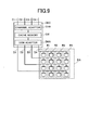
- Fig. 9 is a block diagram schematically illustrating a conventional disk storage system.
- the disk storage system includes a disk controller DKC and a disk array DA.
- the disk controller DKC includes a channel adapter CHA for connecting the disk storage system to a higher-rank CPU (not shown), a cache memory CM for temporarily storing data written in and read out from the disk array DA and a disk adapter DKA for connecting the disk controller DKC to the disk array DA.
- the channel adapter CHA, the cache memory CM and the disk adapter DKA are connected through a bus or switch.
- the channel adapter CHA includes four channels C1, C2, C3 and C4 connected to the CPU.
- the disk adapter DKA is connected to the disk array through four channels D1, D2, D3 and D4.
- the disk array DA includes disk groups R1, R2, R3 and R4.
- the disk groups R1, R2, R3 and R4 each constitute RAID groups.
- Write data inputted from the channels C1, C2, C3 and C4 are stored in the cache memory CM and at the same time the write data are divided into data of block-size unit, so that the data divided in the block unit are sent through three channels of the channels D1, D2, D3 and D4 and a parity calculated from the divided data is sent through a remaining channel from the disk adapter DKA to the disk array DA.
- the data When the data is present in the cache memory CM, the data is read out through the channel adapter CHA from the cache memory CM and transmitted through the channel adapter CHA to the CPU.
- the disk adapter DKA reads out the data divided in the block unit from the disk array DA through the channels D1, D2, D3 and D4 and transmits the read data through the channel adapter CHA to the CPU.
- the conventional technique of this kind is named the first conventional technique.
- the disk storage system related to the first conventional technique is described in, for example, "MAIN FRAME in Separate Volume of Nikkei Computer '98", pp. 144 to 153 issued by Nikkei BP Co. (1998).
- a disk storage system having a disk array connected to a disk adapter through switches is disclosed in JP-A-5-173722 entitled "Exchange Device of Multi-Channel Data and Parity".
- the number of buses related to the disk array and the number of buses related to the disk adapter can be set up independently.
- a disk storage system having a disk array connected to a disk adapter through a buffer control block is disclosed in JP-A-6-19627 entitled "Rotation Type Storage Apparatus”.
- a data transfer rate between the disk adapter and the disk array can be set up to any value and influence due to a waiting time caused by rotation of the disk can be reduced.
- the date transfer rate per channel is increased year after year with the progress of network technique.
- the data transfer rate per channel in a fiber channel used in a disk storage system is 1 to 2 Gbps at present but is planned to be increased to 4 to 10 Gbps in the near future.
- the front-end complies with the above increased data transfer rate.
- the back-end the throughput between the disk adapter and the disk array (hereinafter named the back-end) is not increased as the front-end due to the following reasons.
- the first reason is that the disk drive contains mechanical components and accordingly the high-speed operation is difficult as compared with the front-end including only electronic and optical elements as elements influencing the high-speed operation.
- the second reason is that the cost of the disk storage system having a large number of disk drives is increased when high-speed interfaces are mounted for all of the disk drives even if operation of the disk drives is made fast.
- the first conventional technique has a problem that the performance of the disk storage system is not improved due to detachment of the throughputs of the front-end and the back-end even if the data transfer rate per channel of the channel adapter is improved.
- switches can be provided between the disk adapter and the disk array to thereby increase the number of ports for increased disks, although there is a problem that the data transfer rate per channel is limited to that of the disk array and accordingly the throughput between the disk adapter and the disk array becomes the neck of performance.
- the third conventional technique is a technique capable of reducing influence due to the waiting time caused by rotation of the disk but has a problem that detachment between the front-end and the back-end cannot be reduced.
- the disk storage system includes a disk controller and a disk array and the disk controller includes a channel adapter, a cache memory and a disk adapter.
- the disk adapter is connected to the disk array through a switch having a buffer memory and the data transfer rate per channel between the disk adapter and the switch is set to be higher than that between the switch and the disk array.
- the switch changes over connection between ports connected to which the disk adapter is connected and ports to which disk drives constituting the disk array are connected in accordance with destination information in a frame for each of inputted frames.
- the disk array includes a plurality of disk drives connected into a loop and the disk adapter is connected to the plurality of disk arrays through switches having buffer memories.
- the data transfer rate per channel between the disk adapter and the switch is set to be higher than that between the switch and the plurality of disk arrays and the switch changes over connection between ports to which the disk adapter is connected and ports to which the plurality of disk arrays are connected in accordance with destination information in a frame for each of inputted frames.
- the disk adapter is connected to the disk array through switches having buffer memories and a combination of disk drives connected to the same switch constitutes a RAID group.
- the data transfer rate per channel between the disk adapter and the switch is set to be higher than that between the switch and the disk array and the switch changes over connection between ports to which the disk adapter is connected and ports to which the disk drives constituting the RAID group are connected in accordance with destination information in a frame for each of inputted frames.
- the disk storage system includes first and second disk controllers and a plurality of disk arrays.
- the first disk controller includes a first channel adapter, a first cache memory and a first disk adapter and the second disk controller includes a second channel adapter, a second cache memory and a second disk adapter.
- the first disk adapter is connected to the plurality of disk arrays through a first switch having a buffer memory and the second disk adapter is connected to the plurality of disk arrays through a second switch having a buffer memory. Further, the first switch is connected to the second disk adapter and the second switch is connected to the first disk adapter.
- the data transfer rate per channel between the second disk adapter and the second switch and between the first disk adapter and the second switch is set to be higher than that between the second switch and the plurality of disk arrays.
- the first switch changes over connection between ports to which the first or second disk adapter is connected and ports to which the plurality of disk arrays are connected in accordance with destination information in a frame for each of inputted frames and the second switch changes over connection between ports to which the first or second disk adapter is connected and ports to which the plurality of disk arrays are connected in accordance with destination information in a frame for each of inputted frames.
- the first switch is connected to the second switch through a channel having the same data transfer rate as the channel connected between the first disk adapter and the second switch and a channel having the same data transfer rate as the channel connected between the second disk adapter and the first switch.
- data transferred from the disk array to the switch is multiplexed in the switch to be transferred to the disk adapter and when data is written in the disk array, data transferred from the disk adapter to the switch is demultiplexed in the switch to be transferred to the disk array.
- the disk adapter sets destination information in a frame to be transmitted so that connection between the ports is changed over and when data is read out from the disk array to the disk adapter, the switch changes over connection between ports by the round robin method.
- the number of ports to be changed over is set to be substantially equal to the ratio of the data transfer rate per channel between the disk adapter and the switch to that between the switch and the disk array.
- the disk adapter is connected to the switch through optical fiber cable and the switch is connected to the disk array through metal cable.
- Fig. 1 schematically illustrates a disk storage system according to a first embodiment of the present invention.
- the disk storage system of the embodiment includes a disk controller DKC and a disk array DA.
- the disk controller DKC includes a channel adapter CHA, a cache memory CM and a disk adapter DKA.
- the channel adapter CHA performs control required when data is transmitted and received between a higher-rank CPU (not shown) and the disk controller DKC.
- C1, C2, C3 and C4 represent channels used when the channel adapter CHA communicates with the CPU.
- the cache memory CM is a memory for temporarily storing data inputted/outputted by the disk storage system of the embodiment.
- the disk adapter DKA performs control required when data is transmitted and received between the disk controller DKC and the disk array DA.
- the disk adapter DKA is connected to the disk array DA through channels D01, D02, D03 and D04.
- the disk adapter DKA and the disk array DA can perform the full-duplex operation through the channels D01, D02, D03 and D04.
- the disk adapter DKA and the disk array DA are connected through switches SW1, SW2, SW3 and SW4.
- the disk array DA is composed of disk groups R1, R2, R3 and R4.
- the disk group R1 is connected to the disk adapter DKA through the switch SW1.
- the disk groups R2, R3 and R4 are connected to the disk adapter DKA through the switches SW2, SW3 and SW4, respectively.
- the disk groups R1, R2, R3 and R4 are each the RAID group.
- the RAID group is constituted by four disk drives but the number of disk drives constituting the RAID group is not limited to four.
- R1 is the RAID group of RAID level 5.
- Data transmitted from the CPU through the channels C1, C2, C3 and C4 in order to be written in the disk group R1 is divided into data of block unit in the disk adapter DKA and at the same time a parity is produced from the data divided into the block unit.
- the data divided into the block unit and the parity are supplied through the channel D01 to the switch SW1.
- the switch SW1 performs routing of the data divided into the block unit and the parity in accordance with the RAID control to be distributed to the channels D11, D12, D13 and D14
- the disk adapter DKA reads out data divided into the block unit from the disk group R1 through the channels D11, D12, D13 and D14 and converts the data into serial data in the switch SW1 to receive the read-out data through the channel D01.
- the disk storage system of the embodiment is different from the conventional system in that the data and the parity are distributed on separate channels after the passage of the switch SW1.
- Operation of the switch characterized in the disk storage system of the embodiment is next described by taking the switch SW1 as an example. Operation of the switches SW2 to SW4 is also the same as that of the switch SW1.
- the switch SW1 includes input/output ports P1, P2, P3, P4 and P5.
- the ports P1, P2, P3, P4 and P5 are input/output ports in which the full-duplex operation can be made and each include a buffer memory.
- the internal configuration of the switch SW1 is shown in Figs. 2 and 3.
- data flowing on the channels D01, D11, D12, D13 and D14 are transmitted and received in frame unit and encoded in accordance with the 8B10B encoding scheme.
- Fig. 2 illustrates the circuit configuration in which the frame in a block is inputted from the port P1 and outputted from the ports P2, P3, P4 and P5.
- This operation corresponds to switching operation in writing of data in the disk array.
- the switch SW1 includes a crossbar switch XSW and a switch controller CTL.
- the crossbar switch XSW is of 5 ⁇ 5 and includes input ports in1, in2, in3, in4 and in5 and output ports out1, out2, out3, out4 and out5.
- the frame inputted from the port P1 is supplied through a serial-to-parallel converter SP1, a buffer memory BM1 and an 8B10B decoder DEC1 to the switch controller CTL and the input port in1.
- the switch controller CTL decodes a destination address written in a header portion of the input frame and changes over the crossbar switch XSW.
- the inputted frame passes through the output port out2, an 8B10B encoder ENC2, a buffer memory BM2 and a parallel-to-serial converter PS2 and is outputted from the port P2.
- the buffer memories BM1 and BM2 are FIFO (First-In First-Out) memories.
- the serial-to-parallel converter SP1 converts the 8B10B-encoded serial data into parallel data of 10-bit width and writes the parallel data into the buffer memory BM1 in synchronism with the data transfer rate equal to one tenth of that at the port P1.
- the 8B10B decoder DEC1 reads out the 10-bit parallel data from the buffer memory BM1 in synchronism with the operation speed of the crossbar switch XSW and subjects the 10-bit parallel data to 8B10B decoding to convert it into 8-bit parallel data.
- the 8B10B encoder ENC2 encodes the 8-bit parallel data switched by the crossbar switch XSW into 8B10B-encoded data again to convert it into 10-bit parallel data and writes the data into the buffer memory BM2 in synchronism with the operation speed of the crossbar switch XSW.
- the parallel-to-serial converter PS2 reads out the 10-bit parallel data from the buffer memory BM2 in synchronism with the data transfer rate equal to one tenth of that at the port P2 and converts the data into serial data to be outputted from the port P2.
- the switch SW1 converts the data transfer rate at the port P1 into that at the port P2.
- Fig. 4 is a diagram showing waveforms of the frame inputted to the port P1 and the frame outputted from the ports P2, P3, P4 and P5.
- the high level of the waveforms represents the time that the frame is present and the low level thereof represents the time that the frame is not present.
- the frame has the frame length changing in accordance with the capacity of data to be transmitted, while in this example the sequential access to the disk array is made and the frame length is fixed.
- the data transfer rate at the input port P1 is m times of that at the output ports P2, P3, P4 and P5.
- the duration T1 for the frame Fb2 at the port P1 is extended to the duration T3 upon outputted from the port P2.
- T3 m ⁇ T1.
- the buffer memory at the output port is overflowed unless the switch is changed over periodically, so that the throughput is reduced.
- the changing-over period of switch is T2 ⁇ n ⁇ T1 (the time having no frame is neglected).
- T2 ⁇ T3 is the same as n ⁇ m.
- the condition that the throughput is not reduced in the switch upon writing of data to the disk array is to set the number n of ports of the switch to be changed over periodically to be equal to or larger than a ratio m of the data transfer rate per channel between the disk adapter and the switch to that between the switch and the disk array.
- One of methods of changing over the switch periodically is to make the disk group connected to the switch to be the RAID group.
- the switch is changed over periodically in accordance with the striping control of the RAID.
- Fig. 3 schematically illustrates the circuit configuration in which the frame is inputted from the ports P2, P3, P4 and P5 and outputted from the port P1.
- This operation corresponds to switching operation in reading of data from the disk array.
- the frame inputted from the port P2 is supplied through a serial-to-parallel converter SP2, a buffer memory BM2 and an 8B10B decoder DEC2 to the switch controller CTL and the input port in2.
- the switch controller CTL decodes a destination address written in a header portion of the input frame and changes over the crossbar switch XSW.
- the frame passes through the output port out1, an 8B10B encoder ENC1, the buffer memory BM1 and a parallel-to-serial converter PS1 and is outputted from the port P1.
- the serial-to-parallel converter SP2 converts the 8B10B-encoded serial data into parallel data of 10-bit width and writes it in the buffer memory BM2 in synchronism with the data transfer rate equal to one tenth of that at the port P2.
- the 8B10B decoder DEC2 reads out the 10-bit parallel data from the buffer memory BM2 in synchronism with the operation speed of the crossbar switch XSW and subjects the 10-bit parallel data to 8B10B decoding to convert it into 8-bit parallel data.
- the 8B10B encoder ENC1 encodes the 8-bit parallel data switched by the crossbar XSW into 8B10B-encoded data again to convert it into 10-bit parallel data and writes it into the buffer memory BM1 in synchronism with the operation speed of the crossbar switch XSW.
- the parallel-to-serial converter PS1 reads out the 10-bit parallel data from the buffer memory BM1 in synchronism with the data transfer rate equal to one tenth of that at the port P1 and converts the 10-bit parallel data into serial data to be outputted from the port P1.
- the switch SW1 converts the data transfer rate at the port P2 into that at the port P1.
- Fig. 5 is a diagram showing waveforms of the frame inputted to the ports P2, P3, P4 and P5 and the frame outputted from the port P1.
- the high level of the waveforms represents the time that the frame is present and the low level thereof represents the time that the frame is not present.
- the frame has the frame length changing in accordance with the capacity of data to be transmitted, while in this example the sequential access to the disk array is performed and the frame length is fixed.
- the data transfer rate at the input port P1 is m times of that at the output ports P2, P3, P4 and P5.
- the duration T4 for the frame Fe5 at the port P5 is contracted to the duration T5 upon outputted from the port P1.
- the duration required to output the frames Fe2, Fe3, Fe4 and Fe5 from the port P1 is assumed to be T6.
- T6 ⁇ T4 is required.
- T6 ⁇ T4 is the same as n ⁇ m.
- the condition that the throughput is not reduced in the switch in reading of data to the disk array is to set the number n of ports to be changed over periodically to be equal to or larger than a ratio m of the data transfer rate per channel between the disk adapter and the switch to the data transfer rate per channel between the switch and the disk array.
- n ⁇ m that is, the number of ports to be changed over periodically is required to be set to be substantially equal to the ratio of the data transfer rate per channel between the disk adapter and the switch to the data transfer rate per channel between the switch and the disk array.
- a single channel of 4 Gbps is connected between the disk adapter and the switch and four channels of 1 Gbps are connected between the switch and the disk array.
- a single channel of 10 Gbps is connected between the disk adapter and the switch and four channels of 2 Gbps are connected between the switch and the disk array.
- the data transfer rate at the channels D01, D02, D03 and D04 can be increased even if the data transfer rate at the channels D11, D12, D13 and D14 is low.
- the throughput between the disk adapter DKA and the disk array DA can be improved.
- the fibre channel or the InfiniBand can be used as the data transfer system in the disk storage system of the embodiment.
- Fig. 6 is a diagram illustrating the method of increasing disk drives in the disk storage system of the first embodiment.
- disk groups R5 and R6 are increased as compared with Fig. 1.
- switches having increased ports are used as the switches SW1 and SW2.
- any new channel is not increased and the signal transmission rate of the channel D02 is increased to thereby balance the throughput between the disk adapter side and the disk array side of the switch.
- the switch SW1 8 channels of 1 Gbps are connected between the switch and the disk array and 2 channels of 4 Gbps are connected between the disk adapter and the switch.
- the disk drives can be increased in accordance with the number of ports of the switch.
- This method of increasing the disk drives can be applied to increase the disk drives of the ATA (AT Attachment) system in which the number of drives capable of being connected to one port is small.
- Fig. 7 schematically illustrates a disk storage system according to a second embodiment of the present invention.
- the disk storage system of the embodiment has the configuration of a disk array portion different from the disk storage system of the first embodiment.
- the disk storage system of the embodiment includes a disk controller DKC and four disk arrays DA1, DA2, DA3 and DA4.
- the disk controller DKC includes a channel adapter CHA, a cache memory CM and a disk adapter DKA.
- the disk array DA1 is connected to the disk adapter DKA through a channel D01 and a switch SW1.
- the disk arrays DA2, DA3 and DA4 are connected to the disk adapter DKA through a channel D02 and a switch SW2, a channel D03 and a switch SW3, and a channel D04 and a switch SW4, respectively.
- the switches SW1, SW2, SW3 and SW4 function to perform the rate conversion, the multiplexing and the demultiplexing in the same manner as the first embodiment.
- the fibre channel is used as the data transfer system between the disk adapter DKA and the disk arrays DA1, DA2, DA3 and DA4 through the switches SW1, SW2, SW3 and SW4.
- the switches SW1, SW2, SW3 and SW4 are fibre channel switches.
- the configuration of the disk array in the embodiment is described by taking the disk array DA1 as an example.
- the disk arrays DA1, DA2, DA3 and DA4 have the same drive configuration.
- the disk array DA1 includes a disk array composed of four disks connected to a channel D11, a disk array composed of four disks connected to a channel D12, a disk array composed of four disks connected to the channel D13 and a disk array composed of four disks connected to a channel D14.
- disk drives DK1, DK2, DK3 and DK4 are connected to the channel D11.
- FC-AL fibre channel arbitrated loop
- Fig. 10 shows a connection form of the FC-AL by taking a connection form of the disk drives DK1, DK2, DK3 and DK4 as an example.
- Each of input/output ports of the disk drivers and the switch SW1 is provided with a transmitter Tx and a receiver Rx.
- connection form of the FC-AL is the topology that the input/output ports of the drives and the switch are connected into a loop as shown in Fig. 10, for example.
- the input/output ports of the drives function as NL (Node Loop) ports of the fibre channel.
- the NL port is a port of the apparatus (the disk drive in the embodiment) which makes loop operation.
- the input/output ports of the switch SW1 on the side connected to the disk array DA1 function as FL (Fabric Loop) ports of the fibre channel.
- the FL port is a port of the switch that can connect the FC-AL.
- the FC-AL formed by the channel D11 is a public loop.
- the public loop is a loop that the disk drive on the loop can communicate with a port outside of the loop through the switch.
- the disk drives DK1, DK2, DK3 and DK4 can communicate with the disk adapter DKA through the switch SW1 and the channel D01.
- connection form of the channel D11 has been described by way example, while the channels D12, D13 and D14 are the same as the channel D11.
- the disk groups R1, R2, R3 and R4 are each the RAID group.
- four disk drives constitute the RAID group, although the number of drives constituting the RAID group is not limited to four.
- the FC-AL is used in the channels D11, D12, D13 and D14 to connect the disk drives.
- Up to 126 disk drives can be connected to each of the channels D11, D12, D13 and D14 in accordance with specification of the FC-AL.
- optical fiber cable is used as a medium of the channels D01, D02, D03 and D04 and metal cable is used as a medium of the channels D11, D12, D13 and D14.
- the number of connectable drives per port of the switch can be increased.
- Fig. 8 schematically illustrates a disk storage system according to a third embodiment of the present invention.
- disk controllers and switches are duplicated.
- the fibre channel is used as the data transfer system between disk adapters DKA1, DKA2 and disk array DA1 through switches SW1, SW2.
- the disk storage system of the embodiment includes disk controllers DKC1, DKC2, switches SW1, SW2 and disk array DA1.
- the switches SW1 and SW2 function to perform the rate conversion, the multiplexing and the demultiplexing in the same manner as the first embodiment.
- the disk controller DKC1 includes channel adapter CHA1, cache memory CM1 and disk adapter DKA1.
- the disk controller DKC2 includes channel adapter CHA2, cache memory CM2 and disk adapter DKA2.
- the disk adapter DKA1 is connected to the switch SW1 through channel D1a, the disk adapter DKA2 is connected to the switch SW2 through channel D2a, the disk adapter DKA1 is connected to the switch SW2 through channel D1b and the disk adapter DKA2 is connected to the switch SW1 through channel D2b.
- the disk drives constituting the disk array DA1 each include two input/output ports.
- the disk drives DK1, DK2, DK3 and DK4 are connected to both channels D11 and D21.
- the disk array DA1 includes a disk array composed of four disk drives connected to channels D11 and D21, a disk array composed of four disk drives connected to channels D12 and D22, a disk array composed of four disk drives connected to channels D13 and D23 and a disk array composed of four disk drives connected to channels D14 and D24.
- the channels D11, D12, D13, D14, D21, D22, D23 and D24 are connected to the disk drives by the FC-AL.
- Fig. 11 shows a connection form of the FC-AL in the embodiment by taking a connection form of the disk drives DK1, DK2, DK3 and DK4 as an example.
- Each of the disk drives includes two NL ports.
- a transmitter Tx and a receiver Rx are provided with each of input/output ports of the disk drives and the switches SW1 and SW2.
- the input/output ports of the switches SW1 and SW2 on the side connected to the disk array DA1 are FL ports.
- the switch SW1 and the disk drives DK1, DK2, DK3 and DK4 are connected into a loop by means of the channel D11.
- the switch SW2 and the disk drives DK1, DK2, DK3 and DK4 are connected into a loop by means of the channel D21.
- the two loops are public loops of the fibre channel and the disk drives DK1, DK2, DK3 and DK4 can communicate with the disk adapter DKA1 or DKA2 through the switch SW1 or SW2.
- connection form of the channels D11 and D21 has been described as above by way of example, while the channels D12, D13, D14, D22, D23 and D24 have also the same connection form.
- the disk groups R1, R2, R3 and R4 are each the RAID group.
- four disk drives constitute the RAID group, although the number of drives constituting the RAID group is not limited to four.
- Any of the disk adapters DKA1 and DKA2 can access to all of the disk drives in the disk array DA1.
- the disk storage system of the embodiment uses the channel D1b or D2b as a detour upon failure of the switch SW1 or SW2.
- the disk adapter DKA1 can access to the disk array DA1 through the channel D1b and the switch SW2.
- the disk adapter DKA2 can access to the disk array DA1 through the channel D2b and the switch SW1 and accordingly the disk storage system having high reliability can be realized.
- Fig. 12 schematically illustrates a disk storage system according to a fourth embodiment of the present invention.
- channels D3a and D3b connecting between the switches SW1 and SW2 are provided in the disk storage system of the third embodiment.
- the fibre channel is used as the data transfer system between the disk adapters DKA1, DKA2 and the disk array DA1 through the switches SW1, SW2.
- the disk storage system of the embodiment includes disk controllers DKC1, DKC2, switches SW1, SW2 and disk array DA1.
- the switches SW1 and SW2 function to perform the rate conversion, the multiplexing and the demultiplexing in the same manner as the first embodiment.
- the disk controller DKC1 includes channel adapter CHA1, cache memory CM1 and disk adapter DKA1.
- the disk controller DKC2 includes channel adapter CHA2, cache memory CM2 and disk adapter DKA2.
- the disk adapter DKA1 is connected to the switch SW1 through channel D1a, the disk adapter DKA2 is connected to the switch SW2 through channel D2a, the disk adapter DKA1 is connected to the switch SW2 through channel D1b and the disk adapter DKA2 is connected to the switch SW1 through channel D2b.
- switches SW1 and SW2 are connected to each other through channels D3a and D3b.
- Disk drives constituting the disk array DA1 each include two input/output ports.
- the disk drives DK1, DK2, DK3 and DK4 are connected to both channels D11 and D21.
- the disk array DA1 includes a disk array composed of four disk drives connected to channels D11 and D21, a disk array composed of four disk drives connected to channels D12 and D22, a disk array composed of four disk drives connected to channels D13 and D23 and a disk array composed of four disk drives connected to channels D14 and D24.
- the channels D11, D12, D13, D14, D21, D22, D23 and D24 are connected to the disk drives by the FC-AL as shown in Fig. 11.
- Any of the disk adapters DKA1 and DKA2 can access to all of the disk drives in the disk array DA1.
- the disk groups R1, R2, R3 and R4 are each the RAID groups.
- four disk drives constitute the RAID group, although the number of drives constituting the RAID group is not limited to four.
- the disk adapter DKA1 includes a route (route 1) for accessing to the disk array DA1 through the channel D1a and the switch SW1 and a route (route 2) for accessing to the disk array DA1 through the channel D1b, the switch SW2, the channel D3a and the switch SW1.
- the disk adapter DKA2 includes a route (route 3) for accessing to the disk array DA1 through the channel D2a and the switch SW and a route (route 4) for accessing to the disk array DA1 through the channel D2b, the switch SW1, the channel D3b and the switch SW2.
- channels D1b and D2b are used as detours upon failure of the switch.
- the disk adapter DKA1 can access to the disk array DA1 through the channel D1b and switch SW2.
- the disk adapter DKA2 can access to the disk array DA1 through the channel D2b and the switch SW1.
- the data transfer rate on the channels D1a, D1b, D2a, D2b, D3a and D3b is 2 Gbps per channel and the data transfer rate on the channels D11, D12, D13, D14, D21, D22, D23 and D24 is 1 Gbps per channel.
- the total throughput between the switch SW1 and the disk array DA1 is 4 Gbps.
- the total throughput between the disk adapter DKA1 and the switch SW1 is 4 Gbps by using the routes 1 and 2 as the access route.
- the throughput between the disk adapter DKA1 and the disk array DA1 is 4 Gbps.
- the total throughput between the switch SW2 and the disk array DA1 is 4 Gbps.
- the total throughput between the disk adapter DKA2 and the switch SW2 is 4 Gbps by using the routes 3 and 4 as the access route.
- the throughput between the disk adapter DKA2 and the disk array DA1 is 4 Gbps.
- the throughput between the disk adapter DKA1 and the disk array DA1 is limited to the throughput on the channel D1a and is 2 Gbps since the channels D1b and D2b are used as detours only upon failure of the switch.
- the throughput between the disk adapter DKA2 and the disk array DA1 is limited to the throughput on the channel D2a and is 2 Gbps.
- the disk storage system having the increased total throughput between the disk adapter and the disk array can be realized.
- the disk storage system having the high throughput between the disk adapter and the disk array.
- the disk storage system having the high throughput between the disk adapter and the disk array and the increased disk drives connected in the disk array.
- the disk storage system having the high reliable disk array.
- the disk storage system having the high reliable network between the disk adapter and the disk array.
- the disk storage system having the network between the disk adapter and the disk array with high reliability and high throughput.
- the disk storage system having the high throughput in reading from and writing in the disk.
- the disk storage system capable of keeping the high throughput.
- the disk storage system having the high throughput between the disk adapter and the disk array and a low cost.
Abstract
Description
Claims (9)
- A disk storage system including a disk controller (DKC) and a disk array (DA), said disk controller (DKC) including a channel adapter (CHA), a cache memory (CM) and a disk adapter (DKA), wherein:said disk adapter (DKA) is connected to said disk array (DA) through switches (SW1-4) having buffer memories;a data transfer rate per channel between said disk adapter (DKA) and said switches (SW1-4) being set to be higher than that between said switches (SW1-4) and said disk array (DA): andsaid switches (SW1-4) change over connection between ports to which said disk adapter (DKA) is connected and ports to which disk drives constituting said disk array (DA) are connected in accordance with destination information in a frame for each of inputted frames.
- A disk storage system including a disk controller (DKC) and a plurality of disk arrays (DA1-4), said disk controller (DKC) including a channel adapter (CHA), a cache memory (DA) and a disk adapter (DKA), wherein:said disk arrays (DA1-4) comprise a plurality of disk drives (DK1-4) connected into a loop; andsaid disk adapter (DKA) is connected to said plurality of disk arrays (DA1-4) through switches (SW1-4) having buffer memories;a data transfer rate per channel between said disk adapter (DKA) and said switches (SW1-4) being set to be higher than that between said switches (SW1-4) and said plurality of disk arrays (DA1-4);said switches (SW1-4) change over connection between ports to which said disk adapter (DKA) is connected and ports to which said plurality of disk arrays (DA1-4) are connected in accordance with destination information in a frame for each of inputted frames.
- A disk storage system including a disk controller (DKC) and a disk array (DA), said disk controller (DKC) including a channel adapter (DKA), a cache memory (CM) and a disk adapter (DKA), wherein:said disk adapter (DKA) is connected to said disk array (DA) through switches (SW1-4) having buffer memories; anda combination of disk drives connected to the same switch constitutes a RAID group (R1-4);a data transfer rate per channel between said disk adapter (DKA) and said switches (SW1-4) being set to be higher than that between said switches (SW1-4) and said disk array (DA);said switches change over connection between ports to which said disk adapter (DKA) is connected and ports to which said disk drives constituting said RAID group (R1-4) are connected in accordance with destination information in a frame for each of inputted frames.
- A disk storage system including first and second disk controllers (DKC1, 2) and a plurality of disk arrays (DA);
said first disk controller (DKC1) including a first channel adapter (CHA1), a first cache memory (CM1) and a first disk adapter (DKA1); and
said second disk controller (DKC1) including a second channel adapter (CHA2), a second cache memory (CM2) and a second disk adapter (CKA2);
wherein:said first disk adapter (DKA1) is connected to said plurality of disk arrays (DA) through a first switch (SW1) having a buffer memory and said second disk adapter (DKA2) is connected to said plurality of disk arrays (DA) through a second switch (SW2) having a buffer memory, said first switch (SW1) being connected to said second disk adapter (DKA2), said second switch (SW2) being connected to said first disk adapter (DKA1);a data transfer rate per channel between said first disk adapter (DKA1) and said first switch (SW1) and between said second disk adapter (DKA2) and said first switch (SW1) being set to be higher than that between said first switch (SW1) and said plurality of disk arrays (DA);a data transfer rate per channel between said second disk adapter (DKA2) and said second switch (SW2) and between said first disk adapter (DKA1) and said second switch (SW2) being set to be higher than that between said second switch (SW2) and said plurality of disk arrays (DA);said first switch (SW1) changing over connection between ports to which said first or second disk adapter (DKA1, 2) is connected and ports to which said plurality of disk arrays (DA) are connected in accordance with destination information in a frame for each of inputted frames;said second switch (SW2) changing over connection between ports to which said first or second disk adapter (DKA1, 2) is connected and ports to which said plurality of disk arrays (DA) are connected in accordance with destination information in a frame for each of inputted frames. - A disk storage system including first and second disk controllers (DKC1, 2) and a plurality of disk arrays (DA);
said first disk controller (DKC1) including a first channel adapter (CHA1), a first cache memory (CM1) and a first disk adapter (DKA1);
said second disk controller (DKC2) including a second channel adapter (CHA2), a second cache memory (CM2) and a second disk adapter (DKA2);
wherein:said first disk adapter (DKA1) is connected to said plurality of disk arrays (DA) through a first switch (SW1) having a buffer memory and said second disk adapter (DKA2) is connected to said plurality of disk arrays (DA) through a second switch (SW2) having a buffer memory, said first switch (SW2) being connected to said second disk adapter (DKA2), said second switch (SW2) being connected to said first disk adapter (DKA1);a data transfer rate per channel between said first disk adapter (DKA1) and said first switch (SW1) and between said second disk adapter (DA2) and said first switch (SW1) being set to be higher than that between said first switch (SW1) and said plurality of disk arrays (DA);a data transfer rate per channel between said second disk adapter (DKA2) and said second switch (SW2) and between said first disk adapter (DKA1) and said second switch (SW2) being set to be higher than that between said second switch (SW2) and said plurality of disk arrays (DA);said first switch (SW1) being connected to said second switch (SW2) through a channel having the same data transfer rate as that connected between said first disk adapter (DKA1) and said second switch (SW2) and a channel having the same data transfer rate as that connected between said second disk adapter (DKA2) and said first switch (SW1) ;said first switch (SW1) changing over connection between ports to which said first or second disk adapter (DKA1, 2) or said second switch (SW2) is connected and ports to which said plurality of disk arrays (DA) are connected in accordance with destination information in a frame for each of inputted frames;said second switch (SW2) changing over connection between ports to which said first or second disk adapter (DKA1, 2) or said first switch (SW1) is connected and ports to which said plurality of disk arrays (DA) are connected in accordance with destination information in a frame for each of inputted frames. - A disk storage system according to any of Claims 1 to 5, wherein:data transferred from said disk array (DA) to said switch (SW) is multiplexed in said switch (SW) to be transferred to said disk adapter (DKA) when data is read out from said disk array (DA); anddata transferred from said disk adapter (DKA) to said switch (SW) is demultiplexed in said switch (SW) to be transferred to said disk array (DA) when data is written into said disk array (DA).
- A disk storage system according to any of Claims 1 to 5, wherein:said disk adapter (DKA) sets destination information into a frame to be transmitted so that changing over of connection between said ports is made periodically when data is written into said disk array (DA) from said disk adapter (DKA); andsaid switch (SW) changes over connection between said ports in accordance with a round robin method when data is read out from said disk array (DA) to said disk adapter (DKA).
- A disk storage system according to Claim 7, wherein:the number of ports to be changed over periodically is set to be substantially equal to a ratio of a data transfer rate per channel between said disk adapter (DKA) and said switch (SW) to that between said switch (SW) and said disk array (DKA).
- A disk storage system according to any of Claims 1 to 5, wherein:said disk adapter (DKA) is connected to said switch (SW) through optical fiber cable and said switch is connected to said disk array through metal cable.
Applications Claiming Priority (2)
| Application Number | Priority Date | Filing Date | Title |
|---|---|---|---|
| JP2002106262 | 2002-04-09 | ||
| JP2002106262A JP2003303055A (en) | 2002-04-09 | 2002-04-09 | Disk device connecting disk adapter and array through switch |
Publications (2)
| Publication Number | Publication Date |
|---|---|
| EP1353264A2 true EP1353264A2 (en) | 2003-10-15 |
| EP1353264A3 EP1353264A3 (en) | 2005-12-07 |
Family
ID=28449919
Family Applications (1)
| Application Number | Title | Priority Date | Filing Date |
|---|---|---|---|
| EP02017669A Ceased EP1353264A3 (en) | 2002-04-09 | 2002-08-06 | Disk storage system having disk arrays connected with disk adaptors through switches |
Country Status (4)
| Country | Link |
|---|---|
| US (1) | US6915380B2 (en) |
| EP (1) | EP1353264A3 (en) |
| JP (1) | JP2003303055A (en) |
| CN (2) | CN1920766B (en) |
Cited By (6)
| Publication number | Priority date | Publication date | Assignee | Title |
|---|---|---|---|---|
| GB2401964A (en) * | 2003-05-22 | 2004-11-24 | Hitachi Ltd | Storage unit and circuit for shaping communication signal |
| GB2411022A (en) * | 2004-02-16 | 2005-08-17 | Hitachi Ltd | Disk controller using internal packet multiplex communication |
| EP1662369A3 (en) * | 2004-11-30 | 2008-11-12 | Fujitsu Limited | Data storage system and data storage control device |
| US7467238B2 (en) | 2004-02-10 | 2008-12-16 | Hitachi, Ltd. | Disk controller and storage system |
| US7865665B2 (en) | 2003-11-28 | 2011-01-04 | Hitachi, Ltd. | Storage system for checking data coincidence between a cache memory and a disk drive |
| WO2012095892A1 (en) * | 2011-01-14 | 2012-07-19 | Hitachi, Ltd. | Storage apparatus and response time control method |
Families Citing this family (30)
| Publication number | Priority date | Publication date | Assignee | Title |
|---|---|---|---|---|
| US7346135B1 (en) | 2002-02-13 | 2008-03-18 | Marvell International, Ltd. | Compensation for residual frequency offset, phase noise and sampling phase offset in wireless networks |
| US7263153B2 (en) * | 2002-10-09 | 2007-08-28 | Marvell International, Ltd. | Clock offset compensator |
| US7319705B1 (en) | 2002-10-22 | 2008-01-15 | Marvell International Ltd. | Programmable pre-emphasis circuit for serial ATA |
| JP4483168B2 (en) * | 2002-10-23 | 2010-06-16 | 株式会社日立製作所 | Disk array controller |
| US7752294B2 (en) * | 2002-10-28 | 2010-07-06 | Netapp, Inc. | Method and system for dynamic expansion and contraction of nodes in a storage area network |
| US7246192B1 (en) | 2003-01-10 | 2007-07-17 | Marvell International Ltd. | Serial/parallel ATA controller and converter |
| US8930583B1 (en) | 2003-09-18 | 2015-01-06 | Marvell Israel (M.I.S.L) Ltd. | Method and apparatus for controlling data transfer in a serial-ATA system |
| JP4220887B2 (en) * | 2003-11-17 | 2009-02-04 | 株式会社日立製作所 | Disk device and control method thereof |
| JP4454299B2 (en) | 2003-12-15 | 2010-04-21 | 株式会社日立製作所 | Disk array device and maintenance method of disk array device |
| JP2005267502A (en) * | 2004-03-22 | 2005-09-29 | Hitachi Ltd | Switch for data transfer |
| US20050228943A1 (en) * | 2004-04-02 | 2005-10-13 | Decenzo David P | Multipath redundant storage system architecture and method |
| US20050235080A1 (en) * | 2004-04-16 | 2005-10-20 | Mohamad El-Batal | Speed matching data storage system |
| US7958292B2 (en) | 2004-06-23 | 2011-06-07 | Marvell World Trade Ltd. | Disk drive system on chip with integrated buffer memory and support for host memory access |
| JP4555029B2 (en) * | 2004-09-01 | 2010-09-29 | 株式会社日立製作所 | Disk array device |
| JP4491330B2 (en) * | 2004-11-08 | 2010-06-30 | 富士通株式会社 | Disk array device, data recovery method and data recovery program |
| JP2006244123A (en) * | 2005-03-03 | 2006-09-14 | Fujitsu Ltd | Data storage system and data storage control device |
| JP2006252328A (en) * | 2005-03-11 | 2006-09-21 | Toshiba Corp | Disk array controller, storage system and disk array control method |
| JP4649271B2 (en) * | 2005-06-08 | 2011-03-09 | キヤノン株式会社 | Control device |
| JP4345979B2 (en) * | 2005-06-30 | 2009-10-14 | 富士通株式会社 | RAID device, communication connection monitoring method, and program |
| JP4786312B2 (en) | 2005-11-22 | 2011-10-05 | 株式会社日立製作所 | Storage controller and error information management method for storage controller |
| JP4413184B2 (en) | 2005-11-28 | 2010-02-10 | 富士通株式会社 | Data storage system and data storage control device |
| US7752387B2 (en) * | 2006-03-21 | 2010-07-06 | International Business Machines Corporation | Offloading firmware update tasks from RAID adapter to distributed service processors in switched drive connection network enclosure |
| JP4897387B2 (en) * | 2006-08-10 | 2012-03-14 | 株式会社日立製作所 | Storage apparatus and data management method using the same |
| JP5179031B2 (en) * | 2006-09-13 | 2013-04-10 | 株式会社日立製作所 | Storage system that makes effective use of available ports |
| JP4486633B2 (en) * | 2006-11-16 | 2010-06-23 | 株式会社日立製作所 | Disk array device |
| US7567471B2 (en) * | 2006-12-21 | 2009-07-28 | Intel Corporation | High speed fanned out system architecture and input/output circuits for non-volatile memory |
| JP2008176526A (en) | 2007-01-18 | 2008-07-31 | Hitachi Ltd | Memory control unit and control method therefor |
| US20090055451A1 (en) * | 2007-08-17 | 2009-02-26 | Clay Andre Reimer | Systems and Methods For Providing Redundant Data Storage |
| US20090216942A1 (en) * | 2008-02-23 | 2009-08-27 | Broadcom Corporation | Efficient memory management for hard disk drive (hdd) read channel |
| US8006021B1 (en) * | 2008-03-27 | 2011-08-23 | Xilinx, Inc. | Processor local bus bridge for an embedded processor block core in an integrated circuit |
Citations (2)
| Publication number | Priority date | Publication date | Assignee | Title |
|---|---|---|---|---|
| JPH11353126A (en) * | 1998-06-10 | 1999-12-24 | Nec Corp | Disk array connection system, its fault-occurring device detecting method, and recording medium where control program therefor is recorded |
| JP2000222339A (en) * | 1999-02-02 | 2000-08-11 | Hitachi Ltd | Disk sub-system |
Family Cites Families (8)
| Publication number | Priority date | Publication date | Assignee | Title |
|---|---|---|---|---|
| JP3187525B2 (en) | 1991-05-17 | 2001-07-11 | ヒュンダイ エレクトロニクス アメリカ | Bus connection device |
| JPH0619627A (en) | 1992-06-30 | 1994-01-28 | Hitachi Ltd | Rotary storage |
| US5909594A (en) * | 1997-02-24 | 1999-06-01 | Silicon Graphics, Inc. | System for communications where first priority data transfer is not disturbed by second priority data transfer and where allocated bandwidth is removed when process terminates abnormally |
| US6112276A (en) * | 1997-10-10 | 2000-08-29 | Signatec, Inc. | Modular disk memory apparatus with high transfer rate |
| JP3279248B2 (en) * | 1998-02-27 | 2002-04-30 | 日本電気株式会社 | Switch mechanism, disk array device having the same, and computer system |
| JP3726484B2 (en) | 1998-04-10 | 2005-12-14 | 株式会社日立製作所 | Storage subsystem |
| US6633946B1 (en) * | 1999-09-28 | 2003-10-14 | Sun Microsystems, Inc. | Flexible switch-based I/O system interconnect |
| JP2003084919A (en) * | 2001-09-06 | 2003-03-20 | Hitachi Ltd | Control method of disk array device, and disk array device |
-
2002
- 2002-04-09 JP JP2002106262A patent/JP2003303055A/en active Pending
- 2002-08-06 EP EP02017669A patent/EP1353264A3/en not_active Ceased
- 2002-08-07 US US10/212,882 patent/US6915380B2/en not_active Expired - Fee Related
- 2002-08-27 CN CN2006101389972A patent/CN1920766B/en not_active Expired - Fee Related
- 2002-08-27 CN CN02141918.3A patent/CN1280701C/en not_active Expired - Fee Related
Patent Citations (2)
| Publication number | Priority date | Publication date | Assignee | Title |
|---|---|---|---|---|
| JPH11353126A (en) * | 1998-06-10 | 1999-12-24 | Nec Corp | Disk array connection system, its fault-occurring device detecting method, and recording medium where control program therefor is recorded |
| JP2000222339A (en) * | 1999-02-02 | 2000-08-11 | Hitachi Ltd | Disk sub-system |
Cited By (14)
| Publication number | Priority date | Publication date | Assignee | Title |
|---|---|---|---|---|
| GB2401964B (en) * | 2003-05-22 | 2005-09-14 | Hitachi Ltd | Storage unit and circuit for shaping communication signal |
| GB2401964A (en) * | 2003-05-22 | 2004-11-24 | Hitachi Ltd | Storage unit and circuit for shaping communication signal |
| US7120736B2 (en) | 2003-05-22 | 2006-10-10 | Hitachi, Ltd. | Storage unit and circuit for shaping communication signal |
| DE102004064056B4 (en) * | 2003-11-28 | 2013-01-24 | Hitachi, Ltd. | Disk array system |
| US7865665B2 (en) | 2003-11-28 | 2011-01-04 | Hitachi, Ltd. | Storage system for checking data coincidence between a cache memory and a disk drive |
| US7467238B2 (en) | 2004-02-10 | 2008-12-16 | Hitachi, Ltd. | Disk controller and storage system |
| US7917668B2 (en) | 2004-02-10 | 2011-03-29 | Hitachi, Ltd. | Disk controller |
| GB2411022B (en) * | 2004-02-16 | 2006-03-22 | Hitachi Ltd | Disk controller |
| US7469307B2 (en) | 2004-02-16 | 2008-12-23 | Hitachi, Ltd. | Storage system with DMA controller which controls multiplex communication protocol |
| US7231469B2 (en) | 2004-02-16 | 2007-06-12 | Hitachi, Ltd. | Disk controller |
| GB2411022A (en) * | 2004-02-16 | 2005-08-17 | Hitachi Ltd | Disk controller using internal packet multiplex communication |
| EP1662369A3 (en) * | 2004-11-30 | 2008-11-12 | Fujitsu Limited | Data storage system and data storage control device |
| EP2296085A1 (en) * | 2004-11-30 | 2011-03-16 | Fujitsu Limited | Data storage system and capacity changing method |
| WO2012095892A1 (en) * | 2011-01-14 | 2012-07-19 | Hitachi, Ltd. | Storage apparatus and response time control method |
Also Published As
| Publication number | Publication date |
|---|---|
| EP1353264A3 (en) | 2005-12-07 |
| CN1450443A (en) | 2003-10-22 |
| JP2003303055A (en) | 2003-10-24 |
| CN1920766B (en) | 2011-09-28 |
| CN1920766A (en) | 2007-02-28 |
| US20030191891A1 (en) | 2003-10-09 |
| CN1280701C (en) | 2006-10-18 |
| US6915380B2 (en) | 2005-07-05 |
Similar Documents
| Publication | Publication Date | Title |
|---|---|---|
| EP1353264A2 (en) | Disk storage system having disk arrays connected with disk adaptors through switches | |
| JP4220887B2 (en) | Disk device and control method thereof | |
| US8266353B2 (en) | Serial advanced technology attachment (SATA ) switch | |
| US7523236B1 (en) | Switching serial advanced technology attachment (SATA) to a parallel interface | |
| US7836249B2 (en) | Disk subsystem | |
| US8156270B2 (en) | Dual port serial advanced technology attachment (SATA) disk drive | |
| KR100650818B1 (en) | Method and dedicated frame buffer for loop initialization and responses | |
| US6697914B1 (en) | Switched node comprising a disk controller with integrated multi-port switching circuitry | |
| EP1018686B1 (en) | Disk array controller | |
| US6763409B1 (en) | Switch-on-the-fly GBIC disk channel adapter and disk channel system | |
| US7472210B2 (en) | Multiplexing and bypass circuit for interfacing either single or dual ported drives to multiple storage processors | |
| US20060117159A1 (en) | Data storage system and data storage control device | |
| US20020010834A1 (en) | Load balancing storage system | |
| JPH0969030A (en) | Disk array system | |
| CN1519736A (en) | Magnetic disk storage system | |
| US7096286B2 (en) | Disk array device and method of changing the configuration of the disk array device | |
| JP4444636B2 (en) | Disk subsystem | |
| Weimer | Fibre channel fundamentals | |
| JPH10293633A (en) | Computer system containing optical fiber-channel connection type storage mechanism | |
| JP2006209549A (en) | Data storage system and data storage control unit |
Legal Events
| Date | Code | Title | Description |
|---|---|---|---|
| PUAI | Public reference made under article 153(3) epc to a published international application that has entered the european phase |
Free format text: ORIGINAL CODE: 0009012 |
|
| AK | Designated contracting states |
Kind code of ref document: A2 Designated state(s): AT BE BG CH CY CZ DE DK EE ES FI FR GB GR IE IT LI LU MC NL PT SE SK TR |
|
| AX | Request for extension of the european patent |
Extension state: AL LT LV MK RO SI |
|
| PUAL | Search report despatched |
Free format text: ORIGINAL CODE: 0009013 |
|
| AK | Designated contracting states |
Kind code of ref document: A3 Designated state(s): AT BE BG CH CY CZ DE DK EE ES FI FR GB GR IE IT LI LU MC NL PT SE SK TR |
|
| AX | Request for extension of the european patent |
Extension state: AL LT LV MK RO SI |
|
| 17P | Request for examination filed |
Effective date: 20060308 |
|
| 17Q | First examination report despatched |
Effective date: 20060621 |
|
| AKX | Designation fees paid |
Designated state(s): DE FR GB |
|
| 17Q | First examination report despatched |
Effective date: 20060621 |
|
| STAA | Information on the status of an ep patent application or granted ep patent |
Free format text: STATUS: THE APPLICATION HAS BEEN REFUSED |
|
| 18R | Application refused |
Effective date: 20100218 |