EP1352579B1 - Footwear sole - Google Patents
Footwear sole Download PDFInfo
- Publication number
- EP1352579B1 EP1352579B1 EP03252287A EP03252287A EP1352579B1 EP 1352579 B1 EP1352579 B1 EP 1352579B1 EP 03252287 A EP03252287 A EP 03252287A EP 03252287 A EP03252287 A EP 03252287A EP 1352579 B1 EP1352579 B1 EP 1352579B1
- Authority
- EP
- European Patent Office
- Prior art keywords
- midsole
- lateral
- forefoot
- area
- alignment portion
- Prior art date
- Legal status (The legal status is an assumption and is not a legal conclusion. Google has not performed a legal analysis and makes no representation as to the accuracy of the status listed.)
- Expired - Lifetime
Links
Images


Classifications
-
- A—HUMAN NECESSITIES
- A43—FOOTWEAR
- A43B—CHARACTERISTIC FEATURES OF FOOTWEAR; PARTS OF FOOTWEAR
- A43B7/00—Footwear with health or hygienic arrangements
- A43B7/14—Footwear with health or hygienic arrangements with foot-supporting parts
- A43B7/1405—Footwear with health or hygienic arrangements with foot-supporting parts with pads or holes on one or more locations, or having an anatomical or curved form
- A43B7/1415—Footwear with health or hygienic arrangements with foot-supporting parts with pads or holes on one or more locations, or having an anatomical or curved form characterised by the location under the foot
- A43B7/142—Footwear with health or hygienic arrangements with foot-supporting parts with pads or holes on one or more locations, or having an anatomical or curved form characterised by the location under the foot situated under the medial arch, i.e. under the navicular or cuneiform bones
-
- A—HUMAN NECESSITIES
- A43—FOOTWEAR
- A43B—CHARACTERISTIC FEATURES OF FOOTWEAR; PARTS OF FOOTWEAR
- A43B13/00—Soles; Sole-and-heel integral units
- A43B13/02—Soles; Sole-and-heel integral units characterised by the material
- A43B13/12—Soles with several layers of different materials
- A43B13/125—Soles with several layers of different materials characterised by the midsole or middle layer
-
- A—HUMAN NECESSITIES
- A43—FOOTWEAR
- A43B—CHARACTERISTIC FEATURES OF FOOTWEAR; PARTS OF FOOTWEAR
- A43B13/00—Soles; Sole-and-heel integral units
- A43B13/14—Soles; Sole-and-heel integral units characterised by the constructive form
- A43B13/141—Soles; Sole-and-heel integral units characterised by the constructive form with a part of the sole being flexible, e.g. permitting articulation or torsion
-
- A—HUMAN NECESSITIES
- A43—FOOTWEAR
- A43B—CHARACTERISTIC FEATURES OF FOOTWEAR; PARTS OF FOOTWEAR
- A43B13/00—Soles; Sole-and-heel integral units
- A43B13/14—Soles; Sole-and-heel integral units characterised by the constructive form
- A43B13/16—Pieced soles
-
- A—HUMAN NECESSITIES
- A43—FOOTWEAR
- A43B—CHARACTERISTIC FEATURES OF FOOTWEAR; PARTS OF FOOTWEAR
- A43B13/00—Soles; Sole-and-heel integral units
- A43B13/14—Soles; Sole-and-heel integral units characterised by the constructive form
- A43B13/18—Resilient soles
- A43B13/181—Resiliency achieved by the structure of the sole
- A43B13/186—Differential cushioning region, e.g. cushioning located under the ball of the foot
-
- A—HUMAN NECESSITIES
- A43—FOOTWEAR
- A43B—CHARACTERISTIC FEATURES OF FOOTWEAR; PARTS OF FOOTWEAR
- A43B13/00—Soles; Sole-and-heel integral units
- A43B13/14—Soles; Sole-and-heel integral units characterised by the constructive form
- A43B13/18—Resilient soles
- A43B13/187—Resiliency achieved by the features of the material, e.g. foam, non liquid materials
- A43B13/188—Differential cushioning regions
-
- A—HUMAN NECESSITIES
- A43—FOOTWEAR
- A43B—CHARACTERISTIC FEATURES OF FOOTWEAR; PARTS OF FOOTWEAR
- A43B7/00—Footwear with health or hygienic arrangements
- A43B7/14—Footwear with health or hygienic arrangements with foot-supporting parts
- A43B7/1405—Footwear with health or hygienic arrangements with foot-supporting parts with pads or holes on one or more locations, or having an anatomical or curved form
- A43B7/1415—Footwear with health or hygienic arrangements with foot-supporting parts with pads or holes on one or more locations, or having an anatomical or curved form characterised by the location under the foot
- A43B7/143—Footwear with health or hygienic arrangements with foot-supporting parts with pads or holes on one or more locations, or having an anatomical or curved form characterised by the location under the foot situated under the lateral arch, i.e. the cuboid bone
-
- A—HUMAN NECESSITIES
- A43—FOOTWEAR
- A43B—CHARACTERISTIC FEATURES OF FOOTWEAR; PARTS OF FOOTWEAR
- A43B7/00—Footwear with health or hygienic arrangements
- A43B7/14—Footwear with health or hygienic arrangements with foot-supporting parts
- A43B7/1405—Footwear with health or hygienic arrangements with foot-supporting parts with pads or holes on one or more locations, or having an anatomical or curved form
- A43B7/1415—Footwear with health or hygienic arrangements with foot-supporting parts with pads or holes on one or more locations, or having an anatomical or curved form characterised by the location under the foot
- A43B7/1435—Footwear with health or hygienic arrangements with foot-supporting parts with pads or holes on one or more locations, or having an anatomical or curved form characterised by the location under the foot situated under the joint between the fifth phalange and the fifth metatarsal bone
-
- A—HUMAN NECESSITIES
- A43—FOOTWEAR
- A43B—CHARACTERISTIC FEATURES OF FOOTWEAR; PARTS OF FOOTWEAR
- A43B7/00—Footwear with health or hygienic arrangements
- A43B7/14—Footwear with health or hygienic arrangements with foot-supporting parts
- A43B7/1405—Footwear with health or hygienic arrangements with foot-supporting parts with pads or holes on one or more locations, or having an anatomical or curved form
- A43B7/1415—Footwear with health or hygienic arrangements with foot-supporting parts with pads or holes on one or more locations, or having an anatomical or curved form characterised by the location under the foot
- A43B7/144—Footwear with health or hygienic arrangements with foot-supporting parts with pads or holes on one or more locations, or having an anatomical or curved form characterised by the location under the foot situated under the heel, i.e. the calcaneus bone
Definitions
- the present invention relates to footwear, and more particularly to a sole construction for an article of footwear.
- WO 02/11573 Discloses a midsole having a particularly elastic portion having at least two finger like extensions pointing towards the toe region of the midsole.
- the particularly elastic portion provides flexibility during the wearer's walking motion.
- the aforementioned problems are overcome by the present invention which provides a sole designed specifically to accommodate a woman's gait pattern.
- the midsole defines a foot platform that includes a neutral portion forming a majority of the foot platform and a lateral alignment portion disposed on the lateral side of the sole in the forefoot region.
- the lateral alignment portion is formed from a firmer material than the neutral portion.
- the lateral alignment portion is configured to extend generally from the proximal head of the fifth metatarsal to the distal head of the fifth metatarsal and from the distal head of the fifth metatarsal region to the distal head of the second metatarsal.
- the midsole may further include a forefoot fixing portion disposed beneath the head of the fifth metatarsal within the boundaries of the lateral alignment portion.
- the forefoot fixing portion is manufactured from a softer material than the surrounding lateral alignment portion, and possibly also softer than the neutral portion, to aid in aligning the foot on the sole and provide cushioning to the fifth metatarsal head, which has been determined to be a peak pressure zone for women.
- the midsole further includes a medial alignment portion that extends from a point near the back of the heel through the arch region.
- the medial alignment portion is manufactured from a firmer material than the neutral region, and possibly of the same firmness as the lateral alignment portion.
- the present invention provides a unique footwear sole that is specially configured to correspond with a woman's gait pattern. Unlike conventional footwear, the present invention is configured to address the biomechanical differences between men and women. Among other things, the footwear sole affects the motion, and more specifically, the angular motion of the foot to facilitate alignment of the leg and reduce the rate of migration of the woman's center of mass during each stride.
- the footwear sole helps to provide a woman with a more fluid and balanced stride. In doing so, the sole provides improved comfort and stability for a woman, and may reduce or eliminate the discomfort that can result when wearing conventional footwear that is not configured to match with the unique gait pattern of women. As a result of these benefits, the present invention may also extend the wear-life of the shoe by reinforcing those regions where sole break-down or deterioration is most likely to occur.
- a footwear sole manufactured in accordance with a preferred embodiment of the present invention is shown in Figs. 1a-b , and generally designated 10.
- the footwear sole 10 of the present invention is designed to meet needs specific to a woman's gait pattern and is intended specifically for use in women's footwear.
- the footwear sole 10 includes portions of varying resistance to compression, wherein the size, shape, location and other characteristics of these portions are selected to address biomechanical issues unique to the way in which a woman moves through her stride.
- the footwear sole 10 includes an outsole 12 for engaging the ground and a midsole 14 having different portions that provide different cushioning properties.
- the midsole 14 of the illustrated embodiment includes a neutral portion 20 that forms the majority of the foot platform.
- the midsole 14 also includes a lateral alignment region 16 disposed on the lateral side of the forefoot portion of the sole 10.
- the lateral alignment portion 16 is manufactured from a material that is firmer than the neutral portion 14.
- Pressure profiles describe the topographical pattern of forces under the foot during human movement.
- the profiles describe the orientation of impact forces and how they are attenuated through the natural biomechanism of the human body. They also describe and locate peak concentrations of pressure that may contribute to over load injuries to the connective tissue of the human body, such as muscles, ligaments, tendons and bone.
- Pressure profiles provide a detailed "foot mapping" that is related to how the center of gravity is balanced and how efficiently it is aligned over the foot during human motion.
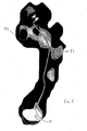
- Fig. 2 shows a typical pressure profile for a man.
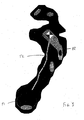
- Fig. 3 shows a typical pressure profile for a woman.
- both men and women exhibit a peak pressure zone P1 under the heel bone, or calcaneus, at foot strike. Women and men differ, however, in the way they compensate for the impact forces as they propel themselves into the next step. Women will typically exhibit another peak pressure zone P2 under the fifth metatarsal bone of the foot and along the lateral border of the foot. Men will typically exhibit a medial peak pressure zone P3 underneath the first metatarsal and big toe, or hallux.
- These pressure profiles also show traces T1 and T2 of the movement of the individuals' center of mass during the stride.
- these traces differ significantly between the male and female profiles.
- the difference between the pressure profiles is due to the anatomical structural differences between men and women.
- the Q-angle of a woman is greater than that of a man.
- a greater Q-angle results in greater stress at the medial knee joint.
- women will typically shift their center of gravity laterally. By shifting their weight to the outside, women naturally bring the leg into straighter alignment. This movement creates a peak pressure zone under the fifth metatarsal head and along the lateral border of the foot.
- This pressure pattern is a normal trend observed in a woman's gait pattern, but is not addressed in conventional shoe designs.
- Rotal impulse is also an important concept to be considered in understanding the natural movement of a woman through her stride.
- “Rotational impulse” is defined as the directional torque generated by the ground reaction forces that are experienced during foot strike. It is a biomechanical measure of how the body adjusts to changes in the center of gravity to maintain balanced alignment over the foot during movement. Because of the lateral shift in their center of gravity, women will typically exhibit a lateral rotational impulse. Arrows R1 and R2 representing typical rotational impulse in a woman's stride are shown in Fig. 7a . A significant number of women will exhibit a lateral rotational impulse trend. One recent study found that 70% of women exhibit a lateral rotational impulse that is significant enough to cause their shoes to prematurely breakdown to the outside and to predispose them to compensatory musculo-skeletal injuries.
- Biomechanical analysis of foot pressure profiles and rotational impulse patterns of women have made it possible to establish a "functional alignment zone" that can be used to improve the functional design of women's footwear.
- the present invention has been developed to incorporate this functional alignment zone into a midsole intended specifically for use in women's footwear.
- the present invention is designed for incorporation into an article of footwear.
- the present invention is described in connection with a conventional footwear sole having an outsole 12 for engaging the ground and a midsole 14 for providing the desired cushion and support.
- the present invention is, however, well-suited for use in essentially any type of sole.
- the footwear sole 10 may include an insole (not shown), sock liner (not shown) or other intermediate sole member disposed above the midsole 14.
- the footwear sole 10 is intended to be secured to an upper (not shown) using essentially any attachment construction, including cement, welt and direct attach constructions.
- the footwear sole 10 may also include a shank or other conventional sole insert, as desired.
- the foot such as the heel, arch and forefoot areas, as well as to specific elements of the foot architecture, such as the hallux, metatarsal bones and calcaneus.
- locations on the midsole these terms should be interpreted to include those areas of the midsole that are disposed generally (and not necessarily directly) beneath and provide support for the corresponding elements of the foot.
- the heel area is generally defined as that area behind (toward the rear of the heel of the sole 10) phantom line A1 (See Fig.
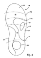
- the arch area is generally defined as that area between phantom lines A1 and A2 and the forefoot region is generally defined as that area ahead of (toward the tiptoe of the sole 10) phantom line A2. It should be understood, however, that the boundaries between the heel, arch and forefoot areas are not precise and that these terms should be interpreted loosely and with a great deal of flexibility.
- the midsole 14 is designed to provide a foot platform that affects the movement pattern of the entire body as a woman moves through her stride. As it is designed to support the foot and to be incorporated into conventional footwear, the midsole 14 is generally foot-shaped. The midsole 14 may, however, take on other shapes, as desired, to accommodate various alternative sole designs. In the illustrated embodiment, the midsole 14 includes a plurality of separate portions that are joined together in a compression molding process to define a continuous support platform. Alternatively, the midsole 14 may include separate and discrete elements that cooperatively support the foot. The midsole 14 includes a generally smooth upper surface 16 designed to support the wearer's foot. The upper surface 16 may include contours, if desired.
- the upper surface 16 of the midsole 14 may be contoured to match the natural contours of the wearer's foot, for example, by providing the upper surface 16 with a concave heel area, a raised arch area or essentially any other desired shape.
- the midsole 14 of the illustrated embodiment includes a peripheral lip 18 that extends upwardly around the peripheral edge of the midsole 14.
- the midsole 14 may directly engage the undersurface of the wearer's foot.
- an intermediate or upper sole member (not shown) will be incorporated into the sole 10.
- an insole (not shown), sock liner (not shown), footbed (not shown) or other sole element may be incorporated into the sole 10 above the midsole 14.
- the midsole 14 generally includes a neutral portion 20 that forms the majority of the foot platform.
- the neutral portion 20 is manufactured from a compression molded EVA with a compressibility of approximately 55 durometer on the Asker C-scale.
- the neutral portion 20 may, however, be manufactured from other cushioning materials and using other manufacturing techniques.
- the neutral portion 20 may be injection molded from polyurethane.
- the neutral portion 20 extends generally through the lateral region of the heel area, the central region of the arch area, the medial region of the forefoot area and throughout essentially the entire toe region.
- the neutral portion 20 preferably extends through the flex zone 60 defined forward of the distal heads of the metatarsals and underlying the proximal phalanges.
- the flex zone 60 is roughly defined as the region between lines F1 and F2 of Fig. 4 .
- the midsole 14 also includes a lateral alignment portion 22 that is positioned to address alignment as a woman moves through her stride. More specifically, the lateral alignment portion 22 is generally disposed on the lateral side of the midsole 14. As a woman moves through her stride, there is a natural tendency for her center of mass to migrate in a lateral direction. The lateral alignment portion 22 helps to control this lateral migration by affecting improved alignment from the foot through to the hip. The precise shape of the lateral alignment portion 22 will vary from application to application.
- the lateral alignment portion 22 is configured to extend from the proximal head of the fifth metatarsal to the distal head of the fifth metatarsal and from the distal head of the fifth metatarsal region to the distal head of the second metatarsal.
- the lateral alignment portion 22 of this embodiment is somewhat triangular in shape having a greater lateral width in the region of the distal heads of the metatarsals.
- the lateral alignment portion 22 preferably, but not necessarily, terminates behind the flex zone 60 so that it does not impair the ability of the sole to flex in that region.
- the flex zone 60 is that portion of the sole ahead of the distal heads of the metatarsals where a majority of the foot flex takes place.
- the flex zone 60 is roughly defined as the region between line F1 and F2 of Fig. 4 .
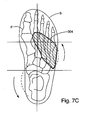
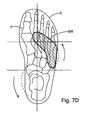
- Examples of alternatively shaped lateral alignment portions are shown in Figs. 7a-d .
- alternatively shaped lateral alignment portions are represented by cross-hatched regions 300, 302, 304 and 306.
- the illustrations also show the outline of the sole S and the general bone structure of the foot F to provide an understanding of the interrelationship between the foot and the alternative lateral alignment portions 300, 302, 304 and 306.
- any one of these alternative lateral alignment portions 300, 302, 304 and 306 can be provided with a forefoot fixing portion (as described in more detail below).
- the lateral alignment portion 22 is manufactured from a compression molded EVA with a compressibility of approximately 65 durometer on the Asker C-scale. Like the neutral portion 20, the lateral alignment portion 22 may, however, be manufactured from other cushioning materials and using other manufacturing techniques.
- the midsole 14 may also include a forefoot fixing portion 24 disposed within the lateral alignment portion 22.
- the forefoot fixing portion 24 is configured to extend beneath the distal head of the fifth metatarsal, which is a peak pressure zone for women.
- the forefoot fixing portion 24 provides less resistance to compression than the lateral alignment portion 22. By positioning it under a peak pressure zone, the forefoot fixing portion 24 not only helps to provide cushioning in a key region, but also to obtain and maintain proper position of the foot on the sole 10. As perhaps best shown in Fig.
- the forefoot fixing portion 24 of this particular embodiment is somewhat elliptical or "tear-drop" in shape extending not only beneath the distal head of the fifth metatarsal but also beneath a portion of the fifth metatarsal bone, thereby providing a line of increased compressibility under the metatarsal bone and further assisting proper alignment of the foot on the sole 10.
- the forefoot fixing portion 24 is manufactured from a compression molded EVA with a compressibility of approximately 40 durometer on the Asker C-scale. Like the neutral portion 20, the forefoot fixing 24 may be manufactured from other cushioning materials and using other manufacturing techniques.
- the midsole 14 of the illustrated embodiment also includes a medial alignment portion 26.
- the medial alignment portion 26 is intended to facilitate proper alignment during the initial stages of a woman's stride, for example, the period beginning at heel strike and extending until the woman's center of mass has migrated to the lateral side of the sole 10.
- the medial alignment portion 26 extends along the medial side of the sole 10 from the heel area through the arch area.
- the medial alignment portion 26 of this embodiment does not extend to the distal heads of the metatarsals.
- the medial alignment portion 26 is manufactured from a compression molded EVA with a compressibility of approximately 65 durometer on the Asker C-scale.
- the medial alignment portion 26 may, however, be manufactured from other cushioning materials and using other manufacturing techniques.
- the midsole 14 also includes a heel fixing portion 28.
- the heel fixing portion 28 cushions the peak pressure point in the heel and helps to center the foot on the sole 10 during the initial stages of each stride, including during heel strike.
- the heel fixing portion 28 includes a disc-shaped insert 50 that is fitted into a corresponding recess 52 in the heel area.
- the insert 50 is manufactured from a relatively soft cushioning material, such as a closed cell foam.
- the size, shape and configuration of the heel fixing portion 28 may vary from application to application.
- the disc-shaped insert 50 and recess 52 combination may be replaced by one or more perforations that reduce the resistance of the corresponding region to compression.
- the insert 50 may define a cutout (not shown), for example, a "star-shaped" cutout.
- the above description identifies certain approximate durometer values for the various portions of the midsole 14 of the illustrated embodiment.
- the recited values are merely exemplary and the present invention is not limited to midsole constructions of the specific recited durometer values.
- the present invention should be broadly interpreted to extend to midsole components having different compressibility values.
- the relative differences in the compressibility of the various portions of the midsole may also vary from application to application.
- the present invention extends to midsoles in which the difference between the compressibility of the neutral portion and the lateral alignment portion varies from the 10 points difference in the above described embodiment.
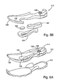
- a sole 110 in accordance with an alternative embodiment of the present invention is shown 5a-b and 6.
- the sole 110 includes an outsole 112 and a midsole 116 (See Fig. 5a ).
- the alternative sole 110 is generally identical to the sole 10 described above, except as specifically described in the following sentences.
- the midsole 114 generally includes a neutral portion 120, a lateral alignment portion 122, a forefoot fixing portion 124, a medial alignment portion 126 and a heel fixing portion 128.
- the forefoot fixing portion 124, medial alignment portion 126 and heel fixing portion 128 are optional.
- the forefoot fixing portion 124 includes an insert 140 that is fitted into a corresponding void 142 in the lateral alignment portion 122, rather than extending entirely through the midsole 114 as in the above described embodiment.
- the insert 140 is manufactured from a material having a substantially lower durometer than the surrounding lateral alignment portion 122.
- the insert 140 may be secured in the void 142 using conventional adhesive, compression molding or other conventional techniques.
- the heel fixing portion 128 is defined by a somewhat "star-shaped" cutout 144 formed in the center of the heel area.
- the cutout 144 may extend entirely or partially through the midsole material depending primarily on the desired compressibility. The size, shape and configuration of the cutout 144 may vary from application to application as desired.
- the midsole 114 may also include a substantially rigid shank 146 to provide support to the arch area of the sole 110.
- An exemplary shank 146 is shown in broken lines in Fig. 6 . The precise size, shape and configuration of the shank 146 may vary from application to application as desired.
- the present invention extends to essentially any midsole construction in which the resistance to compression is varied in accordance with the scope of the present invention as defined in the appended claims, regardless of the way in which varied compression is achieved.
- the compressibility of various regions of the sole is controlled by forming perforations in the midsole 214.
- the midsole 214 is manufactured from a single continuous mass, for example, by injection molding the midsole 214 from a single polyurethane material or by compression molding the midsole 214 from a single EVA material.
- the midsole 214 includes a neutral portion 220 that defines a plurality of perforations 250 in the upper surface of the midsole
- the perforations 250 extend to a depth of approximately one-half the thickness of the midsole 214 at that location.
- the depth of the perforations 250 may vary from application to application.
- the perforations 250 may extend entirely through the midsole 214.
- the perforations 250 may have essentially any cross-sectional shape, but in the illustrated embodiment are generally circular in cross-section.
- the perforations 250 are arranged in a regular pattern throughout a region that is essentially coextensive with the neutral portion 20 of the embodiment described above.
- the perforations 250 may, however, be arranged in an irregular pattern, with more or less perforations 250 in any given portion of the neutral portion 220.
- the perforations 250 in the neutral portion 220 are of about the same size (e.g. diameter), but the size may vary from perforation to perforation, if desired.
- the midsole 214 also includes a lateral alignment portion 222.
- the lateral alignment portion 222 of this embodiment does not include any perforations 250.
- the lateral alignment portion 222 could alternatively include perforations that are configured to give the lateral alignment portion 222 greater resistance to compression than the neutral portion 220.
- the lateral alignment portion 222 may include less perforations, perforations of small size or perforations of lesser depth than the neutral portion 220.
- the midsole 214 may also include a forefoot fixing portion 224 disposed within the lateral alignment portion 222.
- the forefoot fixing portion 224 of the illustrated embodiment is defined by a plurality of perforations 252 disposed within approximately the same location as the forefoot fixing portion 24 of the embodiment described above. That is to say that the forefoot fixing portion 224 is located under the distal head of the fifth metatarsal.
- the perforations 252 have a greater diameter than the perforations in the neutral portion 220 to provide less resistance to compression than either the lateral alignment portion 222 or the neutral portion 220.
- the perforations 252 may be placed closer together, have a greater depth or a different cross sectional shape so that the forefoot fixing portion 224 provides the desired resistance to compression.
- the precise size, shape and configuration of the perforations 252 may vary from application to application.
- the alternative midsole 214 may further include a medial alignment portion 226.
- the medial alignment portion 226 does not include any perforations 250 so that it provides greater resistance to compression than the neutral portion 220.
- the medial alignment portion 226 could alternatively include perforations that are configured to give the medial alignment portion 226 greater resistance to compression than the neutral portion 220.
- the medial alignment portion 226 may include less perforations, perforations of small size or perforations of lesser depth than the neutral portion 220.
- the alternative midsole 214 may also include a heel fixing portion 228.
- the heel fixing portion 228 cushions the peak pressure point in the heel and helps to center the foot on the sole 210 during the initial stages of each stride.
- the heel fixing portion 228 includes a disc-shaped insert 260 that is fitted into a corresponding recess 262 in the heel area.
- the disc-shaped insert 260 may define a somewhat star-shaped cutout 264.
- the size, shape and configuration of the heel fixing portion 228 may vary from application to application.
- the disc-shaped insert 260 may be replaced by one or more perforations that reduce the resistance of the central heel region.
- One specific alternative is to eliminate the disc-shaped insert 260 and to replace it with a somewhat "star-shaped" cutout (See, for example, Fig. 6 ) directly in the midsole material.
- the sole 210 is intended to function with a shank that is disposed above the midsole 114.
- the shank is not shown, the general outline of a shank 270 is shown in Fig. 8 in broken lines. As can be seen, the shank 270 extends through the arch area of the sole 210. Because of the rigidity of the shank 270, the portion of the midsole 214 underlying the shank 270 is not perforated in this embodiment. Although it is permissible to perforate the midsole 214 in the region of the shank 270, the shank's stiffness dramatically reduces the impact of any such perforations. The shank is not necessary and, if included, may be incorporated into the midsole 114 in different ways.
- the shank (not shown) may be secured to the undersurface of the midsole 214 or embedded within the midsole 214.
- perforations may or may not be formed in the shank region depending on the desired characteristics of the midsole 114.
- the midsole 214 may further define one or more flex grooves 280 intended to improve the flexibility of the sole 210. As shown in Fig. 8 , the midsole 214 may define three laterally extending flex grooves 280. In this embodiment, the grooves 280 have a depth of approximately 3.5 millimeters and extend in a line across a majority of the sole width. The size, shape, number and position of the flex grooves may vary from application to application as desired. Flex grooves may be incorporated into any of the embodiments described herein.
- the alternative midsole 214 is intended to be incorporated into an otherwise conventional sole 210.
- the sole 210 preferably includes an outsole (not shown) disposed below the midsole 214.
- a footbed (not shown) disposed above the midsole 214.
- the outsole and footbed may be secured to the midsole 214 by adhesive or other conventional methods.
- the upper (not shown) can be secured to the sole 210 using essentially any conventional techniques and apparatus.
Description
- The present invention relates to footwear, and more particularly to a sole construction for an article of footwear.
- Running shoes, as well as other footwear, have undergone tremendous evolutionary advances in technology over the past 20 years. Many of the technological advances have occurred in the midsole and are the result of knowledge gained from biomechanical studies of human motion. In most footwear, the midsole functions as the suspension system of the sole and it often provides both protective cushioning and a stable platform for the wearer's foot. Many conventional technologies have focused on cushioning the impact associated with foot strike by varying the spring coefficients in the midsole to disperse shock. Relatively recent research has also provided significant clinical guidance in understanding how the complex motions of the foot affect human motion. As a result of that research, many conventional running shoes incorporate some type of stability device in the sole to help provide support to the intricate architecture of the foot. These biomechanical studies and related technological improvements have focused primarily on males, largely ignoring the biomechanical differences between men and women. Accordingly, most conventional biomechanically-designed footwear technology is tailored to address the biomechanical characteristics of a man.
- As a result, studies show that women tend to suffer a disproportionate number of certain walking and running related injuries. For example, studies show that women have a higher incident of injury to the anterior cruciate ligament of the knee. It is believed by many that this is at least in part a result of the unique biomechanical characteristics of women. In many cases, these injuries are addressed by a podiatrist or an orthopaedist, who may prepare custom orthotics that are designed to be fitted into the women's shoes. These orthotics commonly address specific foot abnormalities by varying the shape of the foot using wedges, posts and other similar elements. The precise characteristics of the orthotic insert for a given person will vary based on the specific characteristics of that person's foot and the related injury. Although conventional wedges, posts and other similar elements may relieve pain and reduce the likelihood of repetitive injury for a person, they do so by reshaping the foot to address the specific abnormalities of that person's foot. Conventional orthotics do not properly address the issues raised by underlying differences in the body motion of women. In fact, podiatrists and orthopaedists typically analyze the foot while it is not in a load bearing situation, crafting orthodics or other inserts based on the profile of unloaded feet as well as input from the patient. Further, conventional orthotic inserts are relatively expensive, requiring a person to engage an orthopaedist or podiatrist. Additionally, orthotics and other conventional inserts are placed into the upper of a shoe. By occupying space intended for the foot, these inserts may have a negative impact on the fit and feel of the shoe. Orthotics are also unlikely to alleviate the problem of premature sole breakdown.
-
WO 02/11573 - The aforementioned problems are overcome by the present invention which provides a sole designed specifically to accommodate a woman's gait pattern. The midsole defines a foot platform that includes a neutral portion forming a majority of the foot platform and a lateral alignment portion disposed on the lateral side of the sole in the forefoot region. The lateral alignment portion is formed from a firmer material than the neutral portion. The lateral alignment portion is configured to extend generally from the proximal head of the fifth metatarsal to the distal head of the fifth metatarsal and from the distal head of the fifth metatarsal region to the distal head of the second metatarsal.
- In some applications, the midsole may further include a forefoot fixing portion disposed beneath the head of the fifth metatarsal within the boundaries of the lateral alignment portion. The forefoot fixing portion is manufactured from a softer material than the surrounding lateral alignment portion, and possibly also softer than the neutral portion, to aid in aligning the foot on the sole and provide cushioning to the fifth metatarsal head, which has been determined to be a peak pressure zone for women.
- In yet another embodiment, the midsole further includes a medial alignment portion that extends from a point near the back of the heel through the arch region. The medial alignment portion is manufactured from a firmer material than the neutral region, and possibly of the same firmness as the lateral alignment portion.
- The present invention provides a unique footwear sole that is specially configured to correspond with a woman's gait pattern. Unlike conventional footwear, the present invention is configured to address the biomechanical differences between men and women. Among other things, the footwear sole affects the motion, and more specifically, the angular motion of the foot to facilitate alignment of the leg and reduce the rate of migration of the woman's center of mass during each stride. The footwear sole helps to provide a woman with a more fluid and balanced stride. In doing so, the sole provides improved comfort and stability for a woman, and may reduce or eliminate the discomfort that can result when wearing conventional footwear that is not configured to match with the unique gait pattern of women. As a result of these benefits, the present invention may also extend the wear-life of the shoe by reinforcing those regions where sole break-down or deterioration is most likely to occur.
- These and other objects, advantages, and features of the invention will be readily understood and appreciated by reference to the detailed description of the preferred embodiment and the drawings. Embodiments of the invention will now be described, by way of
example, with reference to the drawings, of which: -
Fig. 1a is a partially exploded perspective view of a sole in accordance with a preferred embodiment of the present invention; -
Fig. 1b is an exploded perspective view of the midsole ofFig. 1a ; -
Fig. 2 is a male pressure profile; -
Fig. 3 is a female pressure profile; -
Fig. 4 is a top plan view of the midsole; -
Fig. 5a is a partially exploded perspective view of an alternative sole; -
Fig. 5b is an exploded perspective view of the midsole ofFig. 5a ; -
Fig. 6 is a top plan view of the alternative midsole; -
Fig. 7a is an illustration of a human foot showing the outline of a sole and an alternative lateral alignment portion; -
Fig. 7b is an illustration of a human foot showing the outline of a sole and a second alternative lateral alignment portion; -
Fig. 7c is an illustration of a human foot showing the outline of a sole and a third alternative lateral alignment portion; -
Fig. 7d is an illustration of a human foot showing the outline of a sole and a fourth alternative lateral alignment portion; and -
Fig. 8 is a top plan view of another alternative sole in which perforations provide differences in compressibility. - A footwear sole manufactured in accordance with a preferred embodiment of the present invention is shown in
Figs. 1a-b , and generally designated 10. Thefootwear sole 10 of the present invention is designed to meet needs specific to a woman's gait pattern and is intended specifically for use in women's footwear. In general, thefootwear sole 10 includes portions of varying resistance to compression, wherein the size, shape, location and other characteristics of these portions are selected to address biomechanical issues unique to the way in which a woman moves through her stride. In the embodiment ofFigs. 1a-b , thefootwear sole 10 includes anoutsole 12 for engaging the ground and amidsole 14 having different portions that provide different cushioning properties. More specifically, themidsole 14 of the illustrated embodiment includes aneutral portion 20 that forms the majority of the foot platform. Themidsole 14 also includes alateral alignment region 16 disposed on the lateral side of the forefoot portion of the sole 10. Thelateral alignment portion 16 is manufactured from a material that is firmer than theneutral portion 14. - Recent biomechanical studies have shown that a woman's gait pattern differs dramatically from that of a man. These differences are largely the result of physical differences in the anatomy of men and women. Perhaps the most dramatic and important difference in terms of gait pattern is the relative pelvic girdle width between men and women. Women generally have a broader pelvis than men. As a result, women typically have a greater angulation from the hip down to the knee, often referred to as the Quadriceps angle, or Q-angle. The degree of angulation of the thigh bone is further increased by the fact that women are generally shorter than men. These factors contribute to provide women with a lower center of gravity.
- Pressure profiles describe the topographical pattern of forces under the foot during human movement. The profiles describe the orientation of impact forces and how they are attenuated through the natural biomechanism of the human body. They also describe and locate peak concentrations of pressure that may contribute to over load injuries to the connective tissue of the human body, such as muscles, ligaments, tendons and bone. Pressure profiles provide a detailed "foot mapping" that is related to how the center of gravity is balanced and how efficiently it is aligned over the foot during human motion.
- The foot pressure profiles of women are significantly different than men because of their biomechanical differences.
Fig. 2 shows a typical pressure profile for a man.Fig. 3 shows a typical pressure profile for a woman. As shown, both men and women exhibit a peak pressure zone P1 under the heel bone, or calcaneus, at foot strike. Women and men differ, however, in the way they compensate for the impact forces as they propel themselves into the next step. Women will typically exhibit another peak pressure zone P2 under the fifth metatarsal bone of the foot and along the lateral border of the foot. Men will typically exhibit a medial peak pressure zone P3 underneath the first metatarsal and big toe, or hallux. These pressure profiles also show traces T1 and T2 of the movement of the individuals' center of mass during the stride. As can be seen, these traces differ significantly between the male and female profiles. The difference between the pressure profiles is due to the anatomical structural differences between men and women. As noted above, the Q-angle of a woman is greater than that of a man. A greater Q-angle results in greater stress at the medial knee joint. To compensate for this misalignment, women will typically shift their center of gravity laterally. By shifting their weight to the outside, women naturally bring the leg into straighter alignment. This movement creates a peak pressure zone under the fifth metatarsal head and along the lateral border of the foot. This pressure pattern is a normal trend observed in a woman's gait pattern, but is not addressed in conventional shoe designs. - The rotational impulse is also an important concept to be considered in understanding the natural movement of a woman through her stride. "Rotational impulse" is defined as the directional torque generated by the ground reaction forces that are experienced during foot strike. It is a biomechanical measure of how the body adjusts to changes in the center of gravity to maintain balanced alignment over the foot during movement. Because of the lateral shift in their center of gravity, women will typically exhibit a lateral rotational impulse. Arrows R1 and R2 representing typical rotational impulse in a woman's stride are shown in
Fig. 7a . A significant number of women will exhibit a lateral rotational impulse trend. One recent study found that 70% of women exhibit a lateral rotational impulse that is significant enough to cause their shoes to prematurely breakdown to the outside and to predispose them to compensatory musculo-skeletal injuries. - Biomechanical analysis of foot pressure profiles and rotational impulse patterns of women have made it possible to establish a "functional alignment zone" that can be used to improve the functional design of women's footwear. The present invention has been developed to incorporate this functional alignment zone into a midsole intended specifically for use in women's footwear.
- As noted above, the present invention is designed for incorporation into an article of footwear. For purposes of disclosure, the present invention is described in connection with a conventional footwear sole having an
outsole 12 for engaging the ground and amidsole 14 for providing the desired cushion and support. The present invention is, however, well-suited for use in essentially any type of sole. Thefootwear sole 10 may include an insole (not shown), sock liner (not shown) or other intermediate sole member disposed above themidsole 14. Thefootwear sole 10 is intended to be secured to an upper (not shown) using essentially any attachment construction, including cement, welt and direct attach constructions. Thefootwear sole 10 may also include a shank or other conventional sole insert, as desired. - To facilitate disclosure of the present invention, reference will be made to various general areas of the foot, such as the heel, arch and forefoot areas, as well as to specific elements of the foot architecture, such as the hallux, metatarsal bones and calcaneus. When used to refer to locations on the midsole, these terms should be interpreted to include those areas of the midsole that are disposed generally (and not necessarily directly) beneath and provide support for the corresponding elements of the foot. For purposes of general reference only, the heel area is generally defined as that area behind (toward the rear of the heel of the sole 10) phantom line A1 (See
Fig. 4 ), the arch area is generally defined as that area between phantom lines A1 and A2 and the forefoot region is generally defined as that area ahead of (toward the tiptoe of the sole 10) phantom line A2. It should be understood, however, that the boundaries between the heel, arch and forefoot areas are not precise and that these terms should be interpreted loosely and with a great deal of flexibility. - The
midsole 14 is designed to provide a foot platform that affects the movement pattern of the entire body as a woman moves through her stride. As it is designed to support the foot and to be incorporated into conventional footwear, themidsole 14 is generally foot-shaped. Themidsole 14 may, however, take on other shapes, as desired, to accommodate various alternative sole designs. In the illustrated embodiment, themidsole 14 includes a plurality of separate portions that are joined together in a compression molding process to define a continuous support platform. Alternatively, themidsole 14 may include separate and discrete elements that cooperatively support the foot. Themidsole 14 includes a generally smoothupper surface 16 designed to support the wearer's foot. Theupper surface 16 may include contours, if desired. For example, theupper surface 16 of themidsole 14 may be contoured to match the natural contours of the wearer's foot, for example, by providing theupper surface 16 with a concave heel area, a raised arch area or essentially any other desired shape. Themidsole 14 of the illustrated embodiment includes aperipheral lip 18 that extends upwardly around the peripheral edge of themidsole 14. Themidsole 14 may directly engage the undersurface of the wearer's foot. In most applications, however, an intermediate or upper sole member (not shown) will be incorporated into the sole 10. For example, an insole (not shown), sock liner (not shown), footbed (not shown) or other sole element may be incorporated into the sole 10 above themidsole 14. - The
midsole 14 generally includes aneutral portion 20 that forms the majority of the foot platform. In one embodiment, theneutral portion 20 is manufactured from a compression molded EVA with a compressibility of approximately 55 durometer on the Asker C-scale. Theneutral portion 20 may, however, be manufactured from other cushioning materials and using other manufacturing techniques. For example, theneutral portion 20 may be injection molded from polyurethane. In the illustrated embodiment, theneutral portion 20 extends generally through the lateral region of the heel area, the central region of the arch area, the medial region of the forefoot area and throughout essentially the entire toe region. To promote flexibility, theneutral portion 20 preferably extends through theflex zone 60 defined forward of the distal heads of the metatarsals and underlying the proximal phalanges. Theflex zone 60 is roughly defined as the region between lines F1 and F2 ofFig. 4 . - The
midsole 14 also includes alateral alignment portion 22 that is positioned to address alignment as a woman moves through her stride. More specifically, thelateral alignment portion 22 is generally disposed on the lateral side of themidsole 14. As a woman moves through her stride, there is a natural tendency for her center of mass to migrate in a lateral direction. Thelateral alignment portion 22 helps to control this lateral migration by affecting improved alignment from the foot through to the hip. The precise shape of thelateral alignment portion 22 will vary from application to application. According to the invention, thelateral alignment portion 22 is configured to extend from the proximal head of the fifth metatarsal to the distal head of the fifth metatarsal and from the distal head of the fifth metatarsal region to the distal head of the second metatarsal. As shown, thelateral alignment portion 22 of this embodiment is somewhat triangular in shape having a greater lateral width in the region of the distal heads of the metatarsals. Thelateral alignment portion 22 preferably, but not necessarily, terminates behind theflex zone 60 so that it does not impair the ability of the sole to flex in that region. Theflex zone 60 is that portion of the sole ahead of the distal heads of the metatarsals where a majority of the foot flex takes place. As noted above, theflex zone 60 is roughly defined as the region between line F1 and F2 ofFig. 4 . Examples of alternatively shaped lateral alignment portions are shown inFigs. 7a-d . In these illustrations, alternatively shaped lateral alignment portions are represented bycross-hatched regions lateral alignment portions lateral alignment portions lateral alignment portion 22 is manufactured from a compression molded EVA with a compressibility of approximately 65 durometer on the Asker C-scale. Like theneutral portion 20, thelateral alignment portion 22 may, however, be manufactured from other cushioning materials and using other manufacturing techniques. - The
midsole 14 may also include aforefoot fixing portion 24 disposed within thelateral alignment portion 22. Theforefoot fixing portion 24 is configured to extend beneath the distal head of the fifth metatarsal, which is a peak pressure zone for women. Theforefoot fixing portion 24 provides less resistance to compression than thelateral alignment portion 22. By positioning it under a peak pressure zone, theforefoot fixing portion 24 not only helps to provide cushioning in a key region, but also to obtain and maintain proper position of the foot on the sole 10. As perhaps best shown inFig. 4 , theforefoot fixing portion 24 of this particular embodiment is somewhat elliptical or "tear-drop" in shape extending not only beneath the distal head of the fifth metatarsal but also beneath a portion of the fifth metatarsal bone, thereby providing a line of increased compressibility under the metatarsal bone and further assisting proper alignment of the foot on the sole 10. In the described embodiment, theforefoot fixing portion 24 is manufactured from a compression molded EVA with a compressibility of approximately 40 durometer on the Asker C-scale. Like theneutral portion 20, the forefoot fixing 24 may be manufactured from other cushioning materials and using other manufacturing techniques. - The
midsole 14 of the illustrated embodiment also includes amedial alignment portion 26. Themedial alignment portion 26 is intended to facilitate proper alignment during the initial stages of a woman's stride, for example, the period beginning at heel strike and extending until the woman's center of mass has migrated to the lateral side of the sole 10. In the illustrated embodiment, themedial alignment portion 26 extends along the medial side of the sole 10 from the heel area through the arch area. Themedial alignment portion 26 of this embodiment does not extend to the distal heads of the metatarsals. In the described embodiment, themedial alignment portion 26 is manufactured from a compression molded EVA with a compressibility of approximately 65 durometer on the Asker C-scale. Themedial alignment portion 26 may, however, be manufactured from other cushioning materials and using other manufacturing techniques. - In the illustrated embodiment, the
midsole 14 also includes aheel fixing portion 28. Theheel fixing portion 28 cushions the peak pressure point in the heel and helps to center the foot on the sole 10 during the initial stages of each stride, including during heel strike. In the illustrated embodiment, theheel fixing portion 28 includes a disc-shapedinsert 50 that is fitted into acorresponding recess 52 in the heel area. Theinsert 50 is manufactured from a relatively soft cushioning material, such as a closed cell foam. The size, shape and configuration of theheel fixing portion 28 may vary from application to application. For example, the disc-shapedinsert 50 andrecess 52 combination may be replaced by one or more perforations that reduce the resistance of the corresponding region to compression. One specific alternative is to replace the disc-shapedinsert 50 andrecess 52 with a star shaped cutout (SeeFigs. 5a-b and6 ) having its center in approximate alignment with the center of the heel area and points that extend outwardly approximately the same distance as the radius of the disc-shapedinsert 50. An alternative embodiment incorporating this alternative construction is described in more detail below. In another alternative, theinsert 50 may define a cutout (not shown), for example, a "star-shaped" cutout. - The above description identifies certain approximate durometer values for the various portions of the
midsole 14 of the illustrated embodiment. The recited values are merely exemplary and the present invention is not limited to midsole constructions of the specific recited durometer values. To the contrary, the present invention should be broadly interpreted to extend to midsole components having different compressibility values. It should also be noted that the relative differences in the compressibility of the various portions of the midsole may also vary from application to application. For example, the present invention extends to midsoles in which the difference between the compressibility of the neutral portion and the lateral alignment portion varies from the 10 points difference in the above described embodiment. - A sole 110 in accordance with an alternative embodiment of the present invention is shown 5a-b and 6. In this embodiment, the sole 110 includes an
outsole 112 and a midsole 116 (SeeFig. 5a ). The alternative sole 110 is generally identical to the sole 10 described above, except as specifically described in the following sentences. In this embodiment, themidsole 114 generally includes aneutral portion 120, alateral alignment portion 122, aforefoot fixing portion 124, amedial alignment portion 126 and aheel fixing portion 128. As with the embodiment described above, theforefoot fixing portion 124,medial alignment portion 126 and heel fixingportion 128 are optional. Theforefoot fixing portion 124 includes an insert 140 that is fitted into a corresponding void 142 in thelateral alignment portion 122, rather than extending entirely through themidsole 114 as in the above described embodiment. The insert 140 is manufactured from a material having a substantially lower durometer than the surroundinglateral alignment portion 122. The insert 140 may be secured in the void 142 using conventional adhesive, compression molding or other conventional techniques. Theheel fixing portion 128 is defined by a somewhat "star-shaped" cutout 144 formed in the center of the heel area. The cutout 144 may extend entirely or partially through the midsole material depending primarily on the desired compressibility. The size, shape and configuration of the cutout 144 may vary from application to application as desired. Themidsole 114 may also include a substantially rigid shank 146 to provide support to the arch area of the sole 110. An exemplary shank 146 is shown in broken lines inFig. 6 . The precise size, shape and configuration of the shank 146 may vary from application to application as desired. - Although described above in connection with midsole constructions having different materials of different durometers, the present invention extends to essentially any midsole construction in which the resistance to compression is varied in accordance with the scope of the present invention as defined in the appended claims, regardless of the way in which varied compression is achieved. In one alternative embodiment, the compressibility of various regions of the sole is controlled by forming perforations in the midsole 214. In this embodiment, the midsole 214 is manufactured from a single continuous mass, for example, by injection molding the midsole 214 from a single polyurethane material or by compression molding the midsole 214 from a single EVA material.
- Referring now to
Fig. 8 , the midsole 214 includes aneutral portion 220 that defines a plurality ofperforations 250 in the upper surface of the midsole In this embodiment, theperforations 250 extend to a depth of approximately one-half the thickness of the midsole 214 at that location. The depth of theperforations 250 may vary from application to application. In some applications, theperforations 250 may extend entirely through the midsole 214. Theperforations 250 may have essentially any cross-sectional shape, but in the illustrated embodiment are generally circular in cross-section. As shown, theperforations 250 are arranged in a regular pattern throughout a region that is essentially coextensive with theneutral portion 20 of the embodiment described above. Theperforations 250 may, however, be arranged in an irregular pattern, with more orless perforations 250 in any given portion of theneutral portion 220. In the illustrated embodiment, theperforations 250 in theneutral portion 220 are of about the same size (e.g. diameter), but the size may vary from perforation to perforation, if desired. - The midsole 214 also includes a
lateral alignment portion 222. To provide greater resistance to compression than theneutral portion 220, thelateral alignment portion 222 of this embodiment does not include anyperforations 250. Thelateral alignment portion 222 could alternatively include perforations that are configured to give thelateral alignment portion 222 greater resistance to compression than theneutral portion 220. For example, thelateral alignment portion 222 may include less perforations, perforations of small size or perforations of lesser depth than theneutral portion 220. - The midsole 214 may also include a
forefoot fixing portion 224 disposed within thelateral alignment portion 222. Theforefoot fixing portion 224 of the illustrated embodiment is defined by a plurality ofperforations 252 disposed within approximately the same location as theforefoot fixing portion 24 of the embodiment described above. That is to say that theforefoot fixing portion 224 is located under the distal head of the fifth metatarsal. In this embodiment, theperforations 252 have a greater diameter than the perforations in theneutral portion 220 to provide less resistance to compression than either thelateral alignment portion 222 or theneutral portion 220. Alternatively or in addition, theperforations 252 may be placed closer together, have a greater depth or a different cross sectional shape so that theforefoot fixing portion 224 provides the desired resistance to compression. The precise size, shape and configuration of theperforations 252 may vary from application to application. - The alternative midsole 214 may further include a
medial alignment portion 226. Like thelateral alignment portion 222, themedial alignment portion 226 does not include anyperforations 250 so that it provides greater resistance to compression than theneutral portion 220. Themedial alignment portion 226 could alternatively include perforations that are configured to give themedial alignment portion 226 greater resistance to compression than theneutral portion 220. For example, themedial alignment portion 226 may include less perforations, perforations of small size or perforations of lesser depth than theneutral portion 220. - The alternative midsole 214 may also include a
heel fixing portion 228. As with the embodiment described above, theheel fixing portion 228 cushions the peak pressure point in the heel and helps to center the foot on the sole 210 during the initial stages of each stride. In the illustrated embodiment, theheel fixing portion 228 includes a disc-shapedinsert 260 that is fitted into acorresponding recess 262 in the heel area. The disc-shapedinsert 260 may define a somewhat star-shaped cutout 264. The size, shape and configuration of theheel fixing portion 228 may vary from application to application. For example, the disc-shapedinsert 260 may be replaced by one or more perforations that reduce the resistance of the central heel region. One specific alternative is to eliminate the disc-shapedinsert 260 and to replace it with a somewhat "star-shaped" cutout (See, for example,Fig. 6 ) directly in the midsole material. - In this alternative embodiment, the sole 210 is intended to function with a shank that is disposed above the
midsole 114. Although the shank is not shown, the general outline of ashank 270 is shown inFig. 8 in broken lines. As can be seen, theshank 270 extends through the arch area of the sole 210. Because of the rigidity of theshank 270, the portion of the midsole 214 underlying theshank 270 is not perforated in this embodiment. Although it is permissible to perforate the midsole 214 in the region of theshank 270, the shank's stiffness dramatically reduces the impact of any such perforations. The shank is not necessary and, if included, may be incorporated into themidsole 114 in different ways. For example, the shank (not shown) may be secured to the undersurface of the midsole 214 or embedded within the midsole 214. In these alternative embodiments, perforations may or may not be formed in the shank region depending on the desired characteristics of themidsole 114. - The midsole 214 may further define one or
more flex grooves 280 intended to improve the flexibility of the sole 210. As shown inFig. 8 , the midsole 214 may define three laterally extendingflex grooves 280. In this embodiment, thegrooves 280 have a depth of approximately 3.5 millimeters and extend in a line across a majority of the sole width. The size, shape, number and position of the flex grooves may vary from application to application as desired. Flex grooves may be incorporated into any of the embodiments described herein. - The alternative midsole 214 is intended to be incorporated into an otherwise conventional sole 210. The sole 210 preferably includes an outsole (not shown) disposed below the midsole 214. A footbed (not shown) disposed above the midsole 214. The outsole and footbed may be secured to the midsole 214 by adhesive or other conventional methods. The upper (not shown) can be secured to the sole 210 using essentially any conventional techniques and apparatus.
- The above description is that of a preferred embodiment of the invention. Various alterations and changes can be made without departing from the invention as defined in the appended claims.
- Any reference to claim elements in the singular, for example, using the articles "a," "an," "the" or "said," is not to be construed as limiting the element to the singular.
Claims (12)
- A midsole (14) for an article of footwear comprising:a forefoot area having a lateral region and a medial region;a neutral portion (20) extending through at least said medial region of said forefoot area; and a lateral alignment portion (22) disposed in at least said lateral region of said forefoot area;said lateral alignment portion extending from an area beneath a proximal head of a fifth metatarsal of a wearer's foot to an area beneath a distal head of a fifth metatarsal of a wearer's foot to an area beneath a distal head of a second metatarsal of a wearer's foot, said lateral alignment portion having a medial edge, all of said medial edge bordered by said neutral portion,said lateral alignment portion having a greater resistance to compression than said neutral portion.
- The midsole of claim 1 further comprising an arch area having a central region and a heel area having a medial region and a lateral region said neutral portion (20) extending at least through said central region, through said arch area and said lateral region of said heel area.
- The midsole (14) of claim 1 further comprising a forefoot fixing portion (24), in use, beneath a distal head of a fifth metatarsal of a wearer's foot, said forefoot fixing portion disposed with said lateral alignment portion (22) and not extending to a lateral edge of said forefoot area, said forefoot fixing portion (24) providing lesser resistance to compression than said lateral alignment portion (22).
- The midsole (14) of claim 3 wherein said forefoot fixing portion (24) provides lesser resistance to compression than said neutral portion (20), and/or further comprising a medial alignment portion (26) extending from said medial region of said heel area through said medial region of said arch area, said medial alignment portion (26) providing greater resistance to compression than said neutral portion (20), and preferably wherein said medial alignment portion (26) and said lateral alignment portion (22) provide substantially equal resistance to compression.
- The midsole (14) of claim 2 further including a flex line extending laterally across the midsole and defined by a natural flex line of a wearer's foot; and wherein said lateral alignment portion (22) does not extend into said flex line; and preferably further including a heel fixing portion (28) disposed in a center of said heel area, said heel fixing portion (28) providing less resistance to compression than said neutral portion (20).
- The midsole (14) of any of claims 1 to 5 wherein said neutral portion (20) is manufactured from a first material and said lateral alignment portion (22) is manufactured from a second material, said first material having a durometer that is less than a durometer of said second material, and preferably wherein said medial alignment portion (26) is manufactured from a third material, said third material having a durometer that is greater than said durometer of said first material or said first material having a durometer that is less than a durometer of said third material, and/or wherein said forefoot fixing portion (24) is manufactured from a fourth material, said fourth material having a durometer that is less than a durometer of said first or second material.
- The midsole (14) of any of claims I to 5 wherein said neutral portion (20) has a durometer value of approximately 55 on the Asker C-Scale, said lateral alignment portion (22) has a durometer value of approximately 65 on the Asker C-Scale, said medial alignment portion (26) has a durometer value of approximately 65 on the Asker C-Scale, and said forefoot fixing portion (24) has a durometer value of approximately 40 on the Asker C-Scale.
- The midsole (14) of any of claims 1 to 5 wherein said neutral portion (20) defines a plurality of perforations providing said neutral portion (20) with less resistance to compression than said lateral alignment portion (22), and preferably wherein said forefoot fixing portion (24) defines one or more perforations providing said forefoot fixing portion (24) with less resistance to compression than said lateral alignment portion (22) and said neutral portion (20).
- A midsole (14) as claimed in claim 1 further comprising a heel area and an arch area wherein said lateral alignment portion (22) extends at least through a lateral portion of the forefoot area.
- The midsole (14) of claim 9 wherein the midsole (14) includes a flex zone (60) extending through a portion of said forefoot area forward, in use, of the distal heads of the metatarsals, said lateral alignment portion (22) not extending into said flex zone (60), or wherein said neutral portion (20) extends at least through substantially all of said flex zone (60).
- The midsole (14) of claim 9 wherein each of said neutral portion (20), said lateral alignment portion (22) and said forefoot fixing portion (24) are compression molded from materials of different durometer values,
- An article of footwear comprising a midsole (14) as claimed in any one of the preceding claims.
Priority Applications (3)
| Application Number | Priority Date | Filing Date | Title |
|---|---|---|---|
| EP07004711A EP1795083B1 (en) | 2002-04-10 | 2003-04-10 | Footwear sole |
| SI200331346T SI1352579T1 (en) | 2002-04-10 | 2003-04-10 | Footwear sole |
| CY20081101011T CY1108353T1 (en) | 2002-04-10 | 2008-09-17 | SHOE SHOE |
Applications Claiming Priority (2)
| Application Number | Priority Date | Filing Date | Title |
|---|---|---|---|
| US37131502P | 2002-04-10 | 2002-04-10 | |
| US371315P | 2002-04-10 |
Related Child Applications (1)
| Application Number | Title | Priority Date | Filing Date |
|---|---|---|---|
| EP07004711A Division EP1795083B1 (en) | 2002-04-10 | 2003-04-10 | Footwear sole |
Publications (2)
| Publication Number | Publication Date |
|---|---|
| EP1352579A1 EP1352579A1 (en) | 2003-10-15 |
| EP1352579B1 true EP1352579B1 (en) | 2008-06-25 |
Family
ID=28454874
Family Applications (1)
| Application Number | Title | Priority Date | Filing Date |
|---|---|---|---|
| EP03252287A Expired - Lifetime EP1352579B1 (en) | 2002-04-10 | 2003-04-10 | Footwear sole |
Country Status (17)
| Country | Link |
|---|---|
| US (1) | US6880266B2 (en) |
| EP (1) | EP1352579B1 (en) |
| JP (1) | JP3942027B2 (en) |
| CN (1) | CN1231158C (en) |
| AR (1) | AR039627A1 (en) |
| AT (1) | ATE398942T1 (en) |
| AU (1) | AU2003203502B2 (en) |
| BR (1) | BR0300932A (en) |
| CA (1) | CA2424807C (en) |
| CY (1) | CY1108353T1 (en) |
| DE (1) | DE60321742D1 (en) |
| DK (1) | DK1352579T3 (en) |
| ES (1) | ES2306843T3 (en) |
| HK (1) | HK1099493A1 (en) |
| MX (1) | MXPA03003163A (en) |
| PT (1) | PT1352579E (en) |
| SI (1) | SI1352579T1 (en) |
Families Citing this family (95)
| Publication number | Priority date | Publication date | Assignee | Title |
|---|---|---|---|---|
| US20120198728A1 (en) * | 2011-02-04 | 2012-08-09 | Freeline Sports, Inc. | Athletic shoe sole for personal transportation device |
| US7549232B2 (en) | 2003-10-14 | 2009-06-23 | Amfit, Inc. | Method to capture and support a 3-D contour |
| DK176311B1 (en) * | 2004-11-08 | 2007-07-23 | Ecco Sko As | Shoes and method of making shoes |
| GB2425242A (en) * | 2005-04-22 | 2006-10-25 | Hi Tec Sports Ltd | Shoe sole product and method |
| WO2006125182A2 (en) * | 2005-05-19 | 2006-11-23 | Danner, Inc. | Footwear with a shank system |
| US7380353B2 (en) * | 2005-07-22 | 2008-06-03 | Ariat International, Inc. | Footwear sole with forefoot stabilizer, ribbed shank, and layered heel cushioning |
| DE202005013282U1 (en) * | 2005-08-22 | 2005-12-22 | Prototec Aktiengesellschaft | Shoe e.g. running shoe, sole for use during exercising sport, has front shoe sole area and rear shoe sole area, which are adhesively formed in single piece, and have clearly tapering width in area of torsion unit |
| DE202005016740U1 (en) * | 2005-10-25 | 2007-03-08 | Shoe Fashion Group Lorenz Ag | Footwear with integrated midfoot roller |
| KR20080066981A (en) * | 2005-11-02 | 2008-07-17 | 스펜코 메디칼 코포레이션 | Shoe insole |
| US7444767B2 (en) * | 2005-11-15 | 2008-11-04 | Nike, Inc. | Article of footwear with midsole having higher density peripheral portion |
| ITPD20060383A1 (en) * | 2006-10-16 | 2008-04-17 | Stilflex S R L | INSOLE FOR SPORTS SHOES, AND IN PARTICULAR FOR THE GOLF GAME |
| US9578922B2 (en) * | 2006-11-06 | 2017-02-28 | Newton Running Company, Inc. | Sole construction for energy storage and rebound |
| US7752773B2 (en) * | 2006-12-01 | 2010-07-13 | Ariat International, Inc. | Advanced torque stability footbed |
| ITTV20070046A1 (en) * | 2007-03-16 | 2008-09-17 | Angelo Scantamburlo | SOLE STRUCTURE OR INSIDE FOOTWEAR INSOLE. |
| US8819961B1 (en) | 2007-06-29 | 2014-09-02 | Frampton E. Ellis | Sets of orthotic or other footwear inserts and/or soles with progressive corrections |
| US20090076772A1 (en) * | 2007-09-18 | 2009-03-19 | Esoles, Llc | Footbeds and a Method and Apparatus for Producing Such Footbeds |
| US8256142B2 (en) * | 2008-02-04 | 2012-09-04 | Sashanaz Hashempour Igdari | Anatomically correct flexible contoured footbed insole |
| DK2247209T3 (en) * | 2008-02-27 | 2017-10-23 | Ecco Sko As | SMOOTHER FOR A SHOE, ESPECIALLY A RUN SHOE |
| US8621765B2 (en) * | 2008-12-09 | 2014-01-07 | Red Wing Shoe Company, Inc. | Molded insole for welted footwear |
| US8845944B2 (en) | 2009-09-02 | 2014-09-30 | Nike, Inc. | Method of manufacturing midsole for article of footwear |
| US8246881B2 (en) | 2009-09-02 | 2012-08-21 | Nike, Inc. | Method of manufacturing sole assembly for article of footwear |
| US20110099845A1 (en) * | 2009-11-03 | 2011-05-05 | Miller Michael J | Customized footwear and methods for manufacturing |
| US20110179675A1 (en) * | 2010-01-14 | 2011-07-28 | Miller Michael J | Sport specific footwear insole |
| US8991072B2 (en) * | 2010-02-22 | 2015-03-31 | Nike, Inc. | Fluid-filled chamber incorporating a flexible plate |
| EP2584928B1 (en) * | 2010-06-25 | 2018-02-14 | Implus Footcare, LLC | Contoured support insole |
| WO2012018744A1 (en) * | 2010-08-02 | 2012-02-09 | Brown Shoe Company, Inc. | Composite sole assembly |
| EP2454959A1 (en) * | 2010-11-19 | 2012-05-23 | Andreas Bennert | A multicomponent sole support assembly for sports footwear |
| US10010131B2 (en) | 2011-02-02 | 2018-07-03 | Implus Footcare, Llc | Flow insole |
| US9107474B2 (en) * | 2011-02-04 | 2015-08-18 | Nike, Inc. | Article of footwear with decoupled upper |
| US20120233877A1 (en) * | 2011-03-18 | 2012-09-20 | Columbia Sportswear North America, Inc. | High-stability multi-density midsole |
| DE102011051444A1 (en) * | 2011-06-29 | 2013-01-03 | Deeluxe Sportartikel Handels Gmbh | Sole for a shoe, especially a running shoe |
| US20130031809A1 (en) * | 2011-08-05 | 2013-02-07 | Roses & Rye LLC | Shoe having improved podiatric support |
| DK2768336T3 (en) * | 2011-10-20 | 2019-05-27 | Gvb Shoetech Ag | Shoe sole for correction or prevention |
| US9095190B2 (en) * | 2012-03-22 | 2015-08-04 | Nike, Inc. | Sole structure configured to allow relative heel/forefoot motion |
| US9936759B2 (en) | 2012-03-22 | 2018-04-10 | Nike, Inc. | Footwear and foot support member configured to allow relative heel/forefoot motion |
| WO2013168256A1 (en) * | 2012-05-10 | 2013-11-14 | 株式会社アシックス | Sole provided with outer sole and midsole |
| SG11201501487RA (en) | 2012-08-31 | 2015-03-30 | Spenco Medical Corp | Basketball insole |
| WO2014071977A1 (en) * | 2012-11-08 | 2014-05-15 | Gvb Shoetech Ag | Sole for pronation control |
| WO2014143692A1 (en) * | 2013-03-15 | 2014-09-18 | Javanscience Llc | Modular shoe systems and methods of using same |
| US9282785B2 (en) | 2013-03-15 | 2016-03-15 | New Balance Athletic Shoe, Inc. | Multi-density sole elements, and systems and methods for manufacturing same |
| US10238168B2 (en) * | 2013-03-15 | 2019-03-26 | Laurence James | Shoe construction |
| US20140325876A1 (en) * | 2013-05-02 | 2014-11-06 | Wolverine World Wide, Inc. | Sole assembly for article of footwear |
| US9622540B2 (en) * | 2013-06-11 | 2017-04-18 | K-Swiss, Inc. | Article of footwear, elements thereof, and related methods of manufacturing |
| USD752325S1 (en) * | 2014-02-07 | 2016-03-29 | New Balance Athletics, Inc. | Shoe sole |
| DK3229636T3 (en) | 2014-12-12 | 2021-07-12 | Harald Beck | Modular insole system for shoe soles |
| DE102015102157A1 (en) * | 2015-02-15 | 2016-08-18 | Jürgen Stumpf | Shoe sole, process for producing such a sole and shoe with such a sole |
| US9861159B2 (en) * | 2015-05-27 | 2018-01-09 | Nike, Inc. | Article of footwear comprising a sole member with apertures |
| CA2980463A1 (en) | 2015-05-28 | 2016-12-01 | Implus Footcare, Llc | Contoured support shoe insole |
| AU2016267588A1 (en) | 2015-05-28 | 2017-12-14 | Implus Footcare, Llc | Contoured support shoe insole |
| WO2016190998A1 (en) | 2015-05-28 | 2016-12-01 | Spenco Medical Corporation | Shoe insole |
| KR20180004126A (en) | 2015-05-28 | 2018-01-10 | 임플러스 풋케어 엘엘씨 | Outlined Shoe Insole |
| USD762366S1 (en) | 2015-06-25 | 2016-08-02 | Spenco Medical Corporation | Shoe insole |
| USD761543S1 (en) | 2015-06-25 | 2016-07-19 | Spenco Medical Corporation | Shoe insole |
| USD758058S1 (en) | 2015-06-25 | 2016-06-07 | Spenco Medical Corporation | Heel cup |
| USD766560S1 (en) | 2015-06-25 | 2016-09-20 | Implus Footcare, Llc | Shoe insole |
| USD762368S1 (en) | 2015-06-25 | 2016-08-02 | Spenco Medical Corporation | Shoe insole |
| USD762367S1 (en) | 2015-06-25 | 2016-08-02 | Spenco Medical Corporation | Shoe insole |
| USD771921S1 (en) | 2015-06-25 | 2016-11-22 | Implus Footcare, Llc | Shoe insole |
| USD797430S1 (en) | 2015-07-15 | 2017-09-19 | Implus Footcare, Llc | Shoe insole |
| USD797428S1 (en) | 2015-07-15 | 2017-09-19 | Implus Footcare, Llc | Shoe insole |
| USD797429S1 (en) | 2015-07-15 | 2017-09-19 | Implus Footcare, Llc | Shoe insole |
| USD771922S1 (en) | 2015-09-15 | 2016-11-22 | Implus Footcare, Llc | Shoe insole |
| USD778567S1 (en) | 2015-09-17 | 2017-02-14 | Implus Footcare, Llc | Shoe insole |
| USD814750S1 (en) | 2015-09-25 | 2018-04-10 | Fourfoot, Llc | Sandal |
| USD778040S1 (en) | 2015-09-25 | 2017-02-07 | Implus Footcare, Llc | Shoe insole |
| US20170164688A1 (en) * | 2015-12-14 | 2017-06-15 | Robert F. Weiss | Orthotic System |
| TWI569743B (en) * | 2016-01-15 | 2017-02-11 | 歐立達股份有限公司 | A device for foot three dimensional motion control and plantar pressure redistribution |
| US10582740B2 (en) | 2016-02-26 | 2020-03-10 | Nike, Inc. | Method of customizing stability in articles of footwear |
| US9867425B2 (en) | 2016-02-26 | 2018-01-16 | Nike, Inc. | Method of customizing forefoot cushioning in articles of footwear |
| US10032202B2 (en) * | 2016-02-26 | 2018-07-24 | Nike, Inc. | Method of custom manufacturing footwear according to a cycle |
| MY176442A (en) * | 2016-04-18 | 2020-08-10 | Lewre Holdings Sdn Bhd | A footwear with customized arch-support midsole and insole, and a method of shoe making |
| US10786040B2 (en) * | 2016-05-26 | 2020-09-29 | Nike, Inc. | Multi-durometer sole structure for an article of footwear |
| US10441028B2 (en) * | 2016-06-20 | 2019-10-15 | Fuerst Group, Inc. | Variable-density soles for articles of footwear |
| US20180020772A1 (en) * | 2016-07-20 | 2018-01-25 | Vionic Group LLC | Composite orthotic device |
| WO2018071301A1 (en) * | 2016-10-10 | 2018-04-19 | Nike Innovate C.V. | Sole structure for an article of footwear with first and second midsole bodies |
| US10485296B2 (en) * | 2016-10-27 | 2019-11-26 | Reebok International Limited | Article of footwear having a midsole with multiple portions and method of making the same |
| US10561199B2 (en) | 2016-11-14 | 2020-02-18 | Deckers Outdoor Corporation | Footwear including a stabilizing sole |
| US11344080B2 (en) * | 2016-11-14 | 2022-05-31 | Deckers Outdoor Corporation | Footwear including a stabilizing sole |
| USD842596S1 (en) | 2017-03-14 | 2019-03-12 | Wolverine Outdoors, Inc. | Footwear sole |
| USD841959S1 (en) | 2017-03-14 | 2019-03-05 | Wolverine Outdoors, Inc. | Footwear sole |
| CN107006931B (en) * | 2017-03-27 | 2019-06-11 | 李宁体育(上海)有限公司 | It is a kind of that the footwear structure of arch of foot dynamic support can be provided |
| EP3568034B1 (en) * | 2017-04-11 | 2022-03-02 | NIKE Innovate C.V. | Articles of footwear including a multi-part sole structure |
| KR20180115990A (en) * | 2017-04-14 | 2018-10-24 | 신관호 | Insole For Adjustment |
| US10932522B2 (en) * | 2017-10-23 | 2021-03-02 | Nike, Inc. | Drop-in unitary footwear sole with first and second cushioning bodies of differing hardness |
| CN108308789A (en) * | 2017-11-22 | 2018-07-24 | 广州万思拓材料科技有限公司 | A kind of personal customization foot based on 3D printing steps on component and preparation method thereof |
| KR102508755B1 (en) | 2018-07-31 | 2023-03-09 | 나이키 이노베이트 씨.브이. | Sole structures for articles of footwear |
| CA3018049A1 (en) | 2018-09-20 | 2020-03-20 | Beck, Harald | Modular insert system for shoe soles |
| US20200170338A1 (en) * | 2018-11-30 | 2020-06-04 | Footwear Unlimited Inc. | Three layer shoe construction with improved cushioning, flexibility, and shock absorption |
| USD916449S1 (en) | 2019-08-29 | 2021-04-20 | Wolverine Outdoors, Inc. | Footwear sole |
| US11000094B2 (en) | 2019-08-29 | 2021-05-11 | Wolverine Outdoors, Inc. | Pain prevention footwear sole |
| USD932157S1 (en) * | 2020-09-29 | 2021-10-05 | Nike, Inc. | Shoe |
| EP4011234A1 (en) * | 2020-12-14 | 2022-06-15 | Ecco Sko A/S | An article of footwear |
| CN114869011A (en) * | 2022-04-27 | 2022-08-09 | 四川大学华西医院 | Orthopedic shoes for foot valgus, flat foot and healthy people |
| CN114794649A (en) * | 2022-04-27 | 2022-07-29 | 四川大学华西医院 | Orthopedic shoes for foot varus and healthy people |
| US20240000185A1 (en) * | 2022-07-01 | 2024-01-04 | Honeywell International Inc. | Outsole for a footwear article |
Family Cites Families (84)
| Publication number | Priority date | Publication date | Assignee | Title |
|---|---|---|---|---|
| BE406522A (en) | 1933-11-30 | |||
| US2266369A (en) | 1939-05-25 | 1941-12-16 | Jules J Kohn | Foot correction |
| US2790254A (en) | 1955-12-06 | 1957-04-30 | William C Burns | Removable shoe pad construction |
| US2857689A (en) | 1956-10-19 | 1958-10-28 | Lorraine A Van Ostrom | Corrective foot support |
| US3081774A (en) | 1960-05-19 | 1963-03-19 | Lelyveld Joseph | Arch support with metatarsal support bar |
| US3985853A (en) | 1974-09-16 | 1976-10-12 | Alex Weisberg | Method of making a combined heel positioner and arch support for the foot |
| US3903621A (en) | 1974-09-26 | 1975-09-09 | Benjamin B Dubner | Conforming supportive innersole device |
| US4137654A (en) | 1977-02-07 | 1979-02-06 | Sports Safety, Inc. | Footwear device |
| DE2709546A1 (en) * | 1977-03-04 | 1978-09-07 | Hans Caesar Knellwolf | Shoe insole or sanitary insert - consists of flexible part and two hard areas and is made of two layers joined together |
| US4180924A (en) | 1978-05-22 | 1980-01-01 | Brooks Shoe Manufacturing Co., Inc. | Running shoe with wedged sole |
| US4219945B1 (en) | 1978-06-26 | 1993-10-19 | Robert C. Bogert | Footwear |
| IT7822471V0 (en) | 1978-07-28 | 1978-07-28 | Sottolana Giulio | INSOLE, ESPECIALLY FOR FEMALE FOOTWEAR. |
| US4235028A (en) | 1978-10-30 | 1980-11-25 | Riggs Donnie E | Orthotic stabilizer for athletic shoe |
| US4268980A (en) | 1978-11-06 | 1981-05-26 | Scholl, Inc. | Detorquing heel control device for footwear |
| US4232457A (en) | 1979-01-31 | 1980-11-11 | Mosher Mitchell R | Orthotic insert |
| US4333472A (en) | 1979-12-31 | 1982-06-08 | Tager Steven E | Compensatory-corrective orthopedic foot devices |
| US4302892A (en) | 1980-04-21 | 1981-12-01 | Sunstar Incorporated | Athletic shoe and sole therefor |
| US4364188A (en) | 1980-10-06 | 1982-12-21 | Wolverine World Wide, Inc. | Running shoe with rear stabilization means |
| US4364189A (en) | 1980-12-05 | 1982-12-21 | Bates Barry T | Running shoe with differential cushioning |
| US4446633A (en) | 1982-06-04 | 1984-05-08 | Scheinhaus Myron G J | Biomechanical footwear |
| JPS6036081Y2 (en) * | 1982-06-26 | 1985-10-26 | 美津濃株式会社 | shoe insole |
| US4910886B1 (en) | 1983-02-28 | 1995-05-09 | Atlantic Thermoplastics Co Inc | Shock-absorbing innersole |
| JPS602201A (en) | 1983-06-20 | 1985-01-08 | 株式会社アサヒコーポレーション | Athletic shoe sole |
| FR2553636B1 (en) | 1983-10-21 | 1986-04-25 | Adidas Chaussures | MIDSOLE AND FOOTWEAR COMPRISING SUCH A MIDSOLE |
| US4597195A (en) | 1984-04-11 | 1986-07-01 | Dananberg Howard J | Human shoe sole |
| JPS6113902A (en) | 1984-06-30 | 1986-01-22 | 株式会社アサヒコーポレーション | Athletic shoes |
| US4627177A (en) | 1984-07-02 | 1986-12-09 | Meyers Stuart R | Insole structure |
| US4615126A (en) | 1984-07-16 | 1986-10-07 | Mathews Dennis P | Footwear for physical exercise |
| US4620376A (en) | 1985-01-22 | 1986-11-04 | Talarico Ii Louis C | Forefoot valgus compensated footwear |
| US4642911A (en) | 1985-02-28 | 1987-02-17 | Talarico Ii Louis C | Dual-compression forefoot compensated footwear |
| US4702255A (en) | 1985-06-17 | 1987-10-27 | Schenkl Joseph L | Orthopedic apparatus |
| US4689898A (en) | 1985-09-11 | 1987-09-01 | Fahey Brian W | Running shoe |
| US4747410A (en) | 1985-11-26 | 1988-05-31 | Cohen Lee S | Cushioned anti-pronation insert |
| US4730402A (en) * | 1986-04-04 | 1988-03-15 | New Balance Athletic Shoe, Inc. | Construction of sole unit for footwear |
| DE3629264A1 (en) | 1986-08-28 | 1988-03-10 | Dassler Puma Sportschuh | HEEL CAP FOR A SHOE, ESPECIALLY SPORTSHOE |
| DE3629212A1 (en) * | 1986-08-28 | 1988-03-03 | Dassler Puma Sportschuh | MIDSOLE FOR SPORTSHOES |
| US4759135A (en) * | 1986-09-11 | 1988-07-26 | Scivoletto Joseph C | Air diffuser and hair lifter attachment for blow dryer |
| US4759136A (en) | 1987-02-06 | 1988-07-26 | Reebok International Ltd. | Athletic shoe with dynamic cradle |
| US5046267A (en) | 1987-11-06 | 1991-09-10 | Nike, Inc. | Athletic shoe with pronation control device |
| US5247742A (en) | 1987-11-06 | 1993-09-28 | Nike, Inc. | Athletic shoe with pronation rearfoot motion control device |
| FR2648707A2 (en) | 1988-07-08 | 1990-12-28 | Pecheux Jean Claude | PASSIVE ARTICULAR MOBILIZING APPARATUS CONTINUES ON THE FOOT |
| US6115941A (en) | 1988-07-15 | 2000-09-12 | Anatomic Research, Inc. | Shoe with naturally contoured sole |
| US5317819A (en) | 1988-09-02 | 1994-06-07 | Ellis Iii Frampton E | Shoe with naturally contoured sole |
| US6314662B1 (en) | 1988-09-02 | 2001-11-13 | Anatomic Research, Inc. | Shoe sole with rounded inner and outer side surfaces |
| US5014706A (en) * | 1988-09-15 | 1991-05-14 | C. Nicolai Gmbh & Co. Kg | Orthotic insole with regions of different hardness |
| US4918841A (en) | 1989-01-30 | 1990-04-24 | Turner Jerome P | Athletic shoe with improved midsole |
| US5077915A (en) | 1989-04-28 | 1992-01-07 | Converse, Inc. | Stress fracture reduction midsole |
| US4984376A (en) | 1989-06-15 | 1991-01-15 | E. I. Du Pont De Nemours And Company | Midsole for footwear |
| US6163982A (en) | 1989-08-30 | 2000-12-26 | Anatomic Research, Inc. | Shoe sole structures |
| ES2155052T3 (en) | 1989-10-03 | 2001-05-01 | Anatomic Res Inc | CORRECTING SOLE FOR SHOES, USING A CONTOUR GREATER THAN THE IDEAL TECHNICAL STABILITY PLAN. |
| US5042174A (en) | 1989-12-01 | 1991-08-27 | K-Swiss Inc. | Novel shoe sole construction |
| US5056535A (en) | 1990-01-22 | 1991-10-15 | Leonard Medical | Varus and valgus leg manipulator |
| US5233767A (en) | 1990-02-09 | 1993-08-10 | Hy Kramer | Article of footwear having improved midsole |
| US5197207A (en) | 1990-05-31 | 1993-03-30 | Tretorn Ab | Shoe, especially a sport or rehabilitation shoe |
| DE9013727U1 (en) * | 1990-10-02 | 1990-12-06 | Erbacher Ski- Und Tennis Ag, 7904 Erbach, De | |
| US5174052A (en) | 1991-01-03 | 1992-12-29 | Schoenhaus Harold D | Dynamic stabilizing inner sole system |
| US5224279A (en) | 1991-06-17 | 1993-07-06 | James Agnew | Athletic shoe sole design and construction |
| US5353523A (en) | 1991-08-02 | 1994-10-11 | Nike, Inc. | Shoe with an improved midsole |
| CA2051230C (en) | 1991-09-12 | 1997-11-18 | Robert Burke | Power midsole cushioning and stability concept |
| US5220737A (en) | 1991-09-27 | 1993-06-22 | Converse Inc. | Shoe sole having improved lateral and medial stability |
| FI924432A0 (en) | 1992-10-01 | 1992-10-01 | Karhu Titan Oy | SULKONSTRUKTION FOER SPORTSKO. |
| US5327663A (en) | 1993-03-18 | 1994-07-12 | Pryce Michael L | Supination control sole and shoe |
| US5878510A (en) | 1993-04-15 | 1999-03-09 | Schoesler; Henning R. | Fluid filled insole |
| DE9305884U1 (en) | 1993-04-21 | 1993-10-21 | Rothhaupt Dirk | Indoor sports shoe special insert |
| TW249196B (en) | 1993-07-23 | 1995-06-11 | James L Throneburg | |
| US5448839A (en) | 1993-10-27 | 1995-09-12 | Wolverine World Wide, Inc. | Stand easy shoe |
| US5771606A (en) | 1994-10-14 | 1998-06-30 | Reebok International Ltd. | Support and cushioning system for an article of footwear |
| KR970701999A (en) * | 1994-04-15 | 1997-05-13 | 스티븐 엘. 루조우 | INSOLE |
| US5611153A (en) | 1994-05-12 | 1997-03-18 | Schering-Plough Healthcare Products, Inc. | Insole for heel pain relief |
| IL111172A (en) | 1994-10-04 | 1998-06-15 | Yitzchak Zohar | Shoes for reducing stress in feet |
| US5718063A (en) | 1995-07-17 | 1998-02-17 | Asics Corporation | Midsole cushioning system |
| US5642575A (en) | 1995-08-25 | 1997-07-01 | Norton; Edward J. | Midsole construction |
| US5678329A (en) | 1996-04-03 | 1997-10-21 | Wilson Sporting Goods Co. | Athletic shoe with midsole side support |
| US5787610A (en) | 1996-05-29 | 1998-08-04 | Jeffrey S. Brooks, Inc. | Footwear |
| US6026599A (en) * | 1996-05-29 | 2000-02-22 | Blackwell; Terry Dean | Pseudo-planar insole insert |
| FR2765779B1 (en) * | 1997-07-11 | 1999-10-15 | Catherine Atlani | RELAXATION SOLE AND SHOE SO EQUIPPED |
| US5852887A (en) | 1997-08-14 | 1998-12-29 | Converse Inc. | Shoe with lateral support member |
| US6108943A (en) | 1998-01-30 | 2000-08-29 | Nike, Inc. | Article of footwear having medial and lateral sides with differing characteristics |
| US6131311A (en) * | 1998-04-17 | 2000-10-17 | Payless Shoesource, Inc. | Insole insert for footwear |
| US6070342A (en) * | 1998-11-16 | 2000-06-06 | Brown; Dennis N. | Contoured insole for footwear |
| DE19904744B4 (en) | 1999-02-05 | 2005-11-10 | Adidas International Marketing B.V. | shoe |
| DE29903764U1 (en) | 1999-03-02 | 1999-06-02 | Adidas Int Bv | shoe |
| US6401366B2 (en) | 1999-04-16 | 2002-06-11 | Nike, Inc. | Athletic shoe with stabilizing frame |
| DK174667B1 (en) * | 2000-08-09 | 2003-08-18 | Ecco Sko As | shoe midsole |
-
2003
- 2003-04-07 AU AU2003203502A patent/AU2003203502B2/en not_active Ceased
- 2003-04-09 AR ARP030101250A patent/AR039627A1/en active IP Right Grant
- 2003-04-09 BR BR0300932-7A patent/BR0300932A/en not_active Application Discontinuation
- 2003-04-09 CA CA002424807A patent/CA2424807C/en not_active Expired - Lifetime
- 2003-04-09 US US10/410,046 patent/US6880266B2/en not_active Expired - Lifetime
- 2003-04-10 DK DK03252287T patent/DK1352579T3/en active
- 2003-04-10 SI SI200331346T patent/SI1352579T1/en unknown
- 2003-04-10 MX MXPA03003163A patent/MXPA03003163A/en active IP Right Grant
- 2003-04-10 ES ES03252287T patent/ES2306843T3/en not_active Expired - Lifetime
- 2003-04-10 CN CNB031360130A patent/CN1231158C/en not_active Expired - Lifetime
- 2003-04-10 DE DE60321742T patent/DE60321742D1/en not_active Expired - Lifetime
- 2003-04-10 JP JP2003106888A patent/JP3942027B2/en not_active Expired - Lifetime
- 2003-04-10 EP EP03252287A patent/EP1352579B1/en not_active Expired - Lifetime
- 2003-04-10 PT PT03252287T patent/PT1352579E/en unknown
- 2003-04-10 AT AT03252287T patent/ATE398942T1/en active
-
2007
- 2007-06-30 HK HK07107018A patent/HK1099493A1/en not_active IP Right Cessation
-
2008
- 2008-09-17 CY CY20081101011T patent/CY1108353T1/en unknown
Also Published As
| Publication number | Publication date |
|---|---|
| ES2306843T3 (en) | 2008-11-16 |
| CN1452927A (en) | 2003-11-05 |
| ATE398942T1 (en) | 2008-07-15 |
| AU2003203502B2 (en) | 2005-05-19 |
| CA2424807C (en) | 2007-11-13 |
| AR039627A1 (en) | 2005-03-02 |
| AU2003203502A1 (en) | 2003-10-30 |
| PT1352579E (en) | 2008-08-05 |
| JP2004000548A (en) | 2004-01-08 |
| US6880266B2 (en) | 2005-04-19 |
| CN1231158C (en) | 2005-12-14 |
| MXPA03003163A (en) | 2004-10-15 |
| US20030192202A1 (en) | 2003-10-16 |
| HK1099493A1 (en) | 2007-08-17 |
| CY1108353T1 (en) | 2014-02-12 |
| CA2424807A1 (en) | 2003-10-10 |
| DE60321742D1 (en) | 2008-08-07 |
| BR0300932A (en) | 2004-06-08 |
| DK1352579T3 (en) | 2008-09-01 |
| JP3942027B2 (en) | 2007-07-11 |
| SI1352579T1 (en) | 2008-12-31 |
| EP1352579A1 (en) | 2003-10-15 |
Similar Documents
| Publication | Publication Date | Title |
|---|---|---|
| EP1352579B1 (en) | Footwear sole | |
| KR101287391B1 (en) | Shoe insole | |
| US6131311A (en) | Insole insert for footwear | |
| US9770066B2 (en) | Neutral posture orienting footbed system for footwear | |
| US6510626B1 (en) | Custom orthotic foot support assembly | |
| US8069586B2 (en) | Orthopedic foot appliance | |
| US20040194344A1 (en) | User-customizable insoles for footwear and method of customizing insoles | |
| US20010032400A1 (en) | Footwear outsole having arcuate inner-structure | |
| EP0164424A1 (en) | Sandal having side wall for preventing pronation | |
| US20110099842A1 (en) | Motion control insole with muscle strengthening component | |
| AU674283B2 (en) | Orthotic device | |
| US6854198B2 (en) | Footwear | |
| US6026599A (en) | Pseudo-planar insole insert | |
| WO2017053168A1 (en) | Sandal with cushioning and contoured support | |
| EP2454959A1 (en) | A multicomponent sole support assembly for sports footwear | |
| US9781971B2 (en) | Integrated medical shoe device | |
| WO2016014922A1 (en) | High heeled shoe with internal comfort and pronation control system | |
| JP5227713B2 (en) | Footwear and internal structure | |
| JP2005013682A (en) | Footwear and insole for footwear | |
| EP1795083B1 (en) | Footwear sole | |
| US20160286895A1 (en) | Footwear | |
| KR101920227B1 (en) | Shoe and method for the construction thereof | |
| CN114765944A (en) | Shoe with dynamic heel support sole | |
| WO1999053785A1 (en) | Insole insert having perforation-modified resiliency | |
| US20220233341A1 (en) | Dynamic Metatarsal Roll Bar |
Legal Events
| Date | Code | Title | Description |
|---|---|---|---|
| PUAI | Public reference made under article 153(3) epc to a published international application that has entered the european phase |
Free format text: ORIGINAL CODE: 0009012 |
|
| AK | Designated contracting states |
Kind code of ref document: A1 Designated state(s): AT BE BG CH CY CZ DE DK EE ES FI FR GB GR HU IE IT LI LU MC NL PT RO SE SI SK TR |
|
| AX | Request for extension of the european patent |
Extension state: AL LT LV MK |
|
| 17P | Request for examination filed |
Effective date: 20031030 |
|
| AKX | Designation fees paid |
Designated state(s): AT BE BG CH CY CZ DE DK EE ES FI FR GB GR HU IE IT LI LU MC NL PT RO SE SI SK TR |
|
| AXX | Extension fees paid |
Extension state: MK Payment date: 20031030 Extension state: AL Payment date: 20031030 Extension state: LT Payment date: 20031030 Extension state: LV Payment date: 20031030 |
|
| 17Q | First examination report despatched |
Effective date: 20050121 |
|
| GRAP | Despatch of communication of intention to grant a patent |
Free format text: ORIGINAL CODE: EPIDOSNIGR1 |
|
| GRAS | Grant fee paid |
Free format text: ORIGINAL CODE: EPIDOSNIGR3 |
|
| GRAA | (expected) grant |
Free format text: ORIGINAL CODE: 0009210 |
|
| RBV | Designated contracting states (corrected) |
Designated state(s): AT BE BG CH CY CZ DE DK EE ES FI FR GR HU IE IT LI LU MC NL PT RO SE SI SK TR |
|
| AK | Designated contracting states |
Kind code of ref document: B1 Designated state(s): AT BE BG CH CY CZ DE DK EE ES FI FR GR HU IE IT LI LU MC NL PT RO SE SI SK TR |
|
| AX | Request for extension of the european patent |
Extension state: AL LT LV MK |
|
| REG | Reference to a national code |
Ref country code: CH Ref legal event code: NV Representative=s name: KIRKER & CIE S.A. Ref country code: CH Ref legal event code: EP |
|
| REG | Reference to a national code |
Ref country code: PT Ref legal event code: SC4A Free format text: AVAILABILITY OF NATIONAL TRANSLATION Effective date: 20080724 |
|
| REF | Corresponds to: |
Ref document number: 60321742 Country of ref document: DE Date of ref document: 20080807 Kind code of ref document: P |
|
| REG | Reference to a national code |
Ref country code: SE Ref legal event code: TRGR |
|
| REG | Reference to a national code |
Ref country code: IE Ref legal event code: FG4D |
|
| REG | Reference to a national code |
Ref country code: DK Ref legal event code: T3 |
|
| REG | Reference to a national code |
Ref country code: RO Ref legal event code: EPE |
|
| REG | Reference to a national code |
Ref country code: GR Ref legal event code: EP Ref document number: 20080402328 Country of ref document: GR |
|
| REG | Reference to a national code |
Ref country code: ES Ref legal event code: FG2A Ref document number: 2306843 Country of ref document: ES Kind code of ref document: T3 |
|
| REG | Reference to a national code |
Ref country code: EE Ref legal event code: FG4A Ref document number: E002393 Country of ref document: EE Effective date: 20080923 |
|
| REG | Reference to a national code |
Ref country code: HU Ref legal event code: AG4A Ref document number: E004390 Country of ref document: HU |
|
| PLBE | No opposition filed within time limit |
Free format text: ORIGINAL CODE: 0009261 |
|
| STAA | Information on the status of an ep patent application or granted ep patent |
Free format text: STATUS: NO OPPOSITION FILED WITHIN TIME LIMIT |
|
| 26N | No opposition filed |
Effective date: 20090326 |
|
| REG | Reference to a national code |
Ref country code: DE Ref legal event code: R082 Ref document number: 60321742 Country of ref document: DE Representative=s name: HUSS, FLOSDORFF & PARTNER GBR, DE Ref country code: DE Ref legal event code: R081 Ref document number: 60321742 Country of ref document: DE Owner name: WOLVERINE OUTDOORS INC., ROCKFORD, US Free format text: FORMER OWNER: WOLVERINE WORLD WIDE INC., ROCKFORD, MICH., US |
|
| REG | Reference to a national code |
Ref country code: FR Ref legal event code: PLFP Year of fee payment: 14 |
|
| REG | Reference to a national code |
Ref country code: FR Ref legal event code: TP Owner name: WOLVERINE OUTDOORS, INC., US Effective date: 20160524 |
|
| REG | Reference to a national code |
Ref country code: CH Ref legal event code: PUE Owner name: WOLVERINE OUTDOORS, INC., US Free format text: FORMER OWNER: WOLVERINE WORLD WIDE, INC., US |
|
| REG | Reference to a national code |
Ref country code: EE Ref legal event code: GB1A Ref document number: E002393 Country of ref document: EE |
|
| REG | Reference to a national code |
Ref country code: HU Ref legal event code: GB9C Owner name: WOLVERINE OUTDOORS, INC., US Free format text: FORMER OWNER(S): WOLVERINE WORLD WIDE, INC., US |
|
| REG | Reference to a national code |
Ref country code: AT Ref legal event code: PC Ref document number: 398942 Country of ref document: AT Kind code of ref document: T Owner name: WOLVERINE OUTDOORS, INC., US Effective date: 20160630 |
|
| REG | Reference to a national code |
Ref country code: ES Ref legal event code: PC2A Owner name: WOLVERINE OUTDOORS, INC. Effective date: 20160824 |
|
| REG | Reference to a national code |
Ref country code: SI Ref legal event code: SP73 Owner name: WOLVERINE OUTDOORS, INC.; US Effective date: 20160706 |
|
| REG | Reference to a national code |
Ref country code: NL Ref legal event code: PD Owner name: WOLVERINE OUTDOORS, INC.; US Free format text: DETAILS ASSIGNMENT: VERANDERING VAN EIGENAAR(S), OVERDRACHT; FORMER OWNER NAME: WOLVERINE WORLD WIDE, INC. Effective date: 20160622 |
|
| REG | Reference to a national code |
Ref country code: SK Ref legal event code: PC4A Ref document number: E 4077 Country of ref document: SK Owner name: WOLVERINE OUTDOORS, INC., ROCKFORD, MI, US Free format text: FORMER OWNER: WOLVERINE WORLD WIDE, INC., ROCKFORD, MICHIGAN, US Effective date: 20161007 |
|
| REG | Reference to a national code |
Ref country code: FR Ref legal event code: PLFP Year of fee payment: 15 |
|
| REG | Reference to a national code |
Ref country code: CH Ref legal event code: NV Representative=s name: KATZAROV S.A., CH |
|
| REG | Reference to a national code |
Ref country code: CH Ref legal event code: PCAR Free format text: NEW ADDRESS: AVENUE DES MORGINES 12, 1213 PETIT-LANCY (CH) |
|
| REG | Reference to a national code |
Ref country code: FR Ref legal event code: PLFP Year of fee payment: 16 |
|
| PGFP | Annual fee paid to national office [announced via postgrant information from national office to epo] |
Ref country code: IE Payment date: 20220328 Year of fee payment: 20 Ref country code: FI Payment date: 20220328 Year of fee payment: 20 Ref country code: DK Payment date: 20220328 Year of fee payment: 20 Ref country code: CH Payment date: 20220318 Year of fee payment: 20 Ref country code: BG Payment date: 20220330 Year of fee payment: 20 |
|
| PGFP | Annual fee paid to national office [announced via postgrant information from national office to epo] |
Ref country code: SK Payment date: 20220329 Year of fee payment: 20 Ref country code: PT Payment date: 20220328 Year of fee payment: 20 Ref country code: NL Payment date: 20220322 Year of fee payment: 20 Ref country code: MC Payment date: 20220329 Year of fee payment: 20 Ref country code: LU Payment date: 20220327 Year of fee payment: 20 Ref country code: GR Payment date: 20220328 Year of fee payment: 20 Ref country code: FR Payment date: 20220324 Year of fee payment: 20 Ref country code: EE Payment date: 20220321 Year of fee payment: 20 Ref country code: CZ Payment date: 20220318 Year of fee payment: 20 Ref country code: BE Payment date: 20220322 Year of fee payment: 20 |
|
| PGFP | Annual fee paid to national office [announced via postgrant information from national office to epo] |
Ref country code: SE Payment date: 20220408 Year of fee payment: 20 Ref country code: RO Payment date: 20220401 Year of fee payment: 20 Ref country code: IT Payment date: 20220412 Year of fee payment: 20 Ref country code: HU Payment date: 20220326 Year of fee payment: 20 Ref country code: ES Payment date: 20220511 Year of fee payment: 20 Ref country code: DE Payment date: 20220318 Year of fee payment: 20 Ref country code: CY Payment date: 20220411 Year of fee payment: 20 |
|
| PGFP | Annual fee paid to national office [announced via postgrant information from national office to epo] |
Ref country code: TR Payment date: 20220406 Year of fee payment: 20 Ref country code: SI Payment date: 20220318 Year of fee payment: 20 Ref country code: AT Payment date: 20220328 Year of fee payment: 20 |
|
| REG | Reference to a national code |
Ref country code: DE Ref legal event code: R071 Ref document number: 60321742 Country of ref document: DE |
|
| REG | Reference to a national code |
Ref country code: NL Ref legal event code: MK Effective date: 20230409 |
|
| REG | Reference to a national code |
Ref country code: CH Ref legal event code: PL |
|
| REG | Reference to a national code |
Ref country code: DK Ref legal event code: EUP Expiry date: 20230410 |
|
| REG | Reference to a national code |
Ref country code: LT Ref legal event code: MM9A Effective date: 20230410 |
|
| REG | Reference to a national code |
Ref country code: SK Ref legal event code: MK4A Ref document number: E 4077 Country of ref document: SK Expiry date: 20230410 |
|
| PG25 | Lapsed in a contracting state [announced via postgrant information from national office to epo] |
Ref country code: CZ Free format text: LAPSE BECAUSE OF EXPIRATION OF PROTECTION Effective date: 20230410 |
|
| REG | Reference to a national code |
Ref country code: ES Ref legal event code: FD2A Effective date: 20230428 |
|
| REG | Reference to a national code |
Ref country code: BE Ref legal event code: MK Effective date: 20230410 |
|
| REG | Reference to a national code |
Ref country code: AT Ref legal event code: MK07 Ref document number: 398942 Country of ref document: AT Kind code of ref document: T Effective date: 20230410 |
|
| REG | Reference to a national code |
Ref country code: IE Ref legal event code: MK9A |
|
| REG | Reference to a national code |
Ref country code: SE Ref legal event code: EUG |
|
| PG25 | Lapsed in a contracting state [announced via postgrant information from national office to epo] |
Ref country code: SI Free format text: LAPSE BECAUSE OF EXPIRATION OF PROTECTION Effective date: 20230411 |
|
| P01 | Opt-out of the competence of the unified patent court (upc) registered |
Effective date: 20230522 |
|
| PG25 | Lapsed in a contracting state [announced via postgrant information from national office to epo] |
Ref country code: PT Free format text: LAPSE BECAUSE OF EXPIRATION OF PROTECTION Effective date: 20230420 Ref country code: IE Free format text: LAPSE BECAUSE OF EXPIRATION OF PROTECTION Effective date: 20230410 Ref country code: ES Free format text: LAPSE BECAUSE OF EXPIRATION OF PROTECTION Effective date: 20230411 |
|
| PG25 | Lapsed in a contracting state [announced via postgrant information from national office to epo] |
Ref country code: SK Free format text: LAPSE BECAUSE OF EXPIRATION OF PROTECTION Effective date: 20230410 |