EP1350955A2 - Peristaltic pump - Google Patents
Peristaltic pump Download PDFInfo
- Publication number
- EP1350955A2 EP1350955A2 EP03007783A EP03007783A EP1350955A2 EP 1350955 A2 EP1350955 A2 EP 1350955A2 EP 03007783 A EP03007783 A EP 03007783A EP 03007783 A EP03007783 A EP 03007783A EP 1350955 A2 EP1350955 A2 EP 1350955A2
- Authority
- EP
- European Patent Office
- Prior art keywords
- tubing
- pump
- platen
- occluder
- operatively arranged
- Prior art date
- Legal status (The legal status is an assumption and is not a legal conclusion. Google has not performed a legal analysis and makes no representation as to the accuracy of the status listed.)
- Granted
Links
- 230000002572 peristaltic effect Effects 0.000 title 1
- 239000012530 fluid Substances 0.000 claims abstract description 35
- 238000005086 pumping Methods 0.000 claims abstract description 8
- 238000001802 infusion Methods 0.000 claims description 20
- 238000000034 method Methods 0.000 claims description 11
- 239000003990 capacitor Substances 0.000 claims description 9
- 230000000881 depressing effect Effects 0.000 claims description 4
- 238000004891 communication Methods 0.000 claims description 3
- 238000001990 intravenous administration Methods 0.000 description 7
- 239000004800 polyvinyl chloride Substances 0.000 description 5
- 229920000915 polyvinyl chloride Polymers 0.000 description 4
- XUIMIQQOPSSXEZ-UHFFFAOYSA-N Silicon Chemical compound [Si] XUIMIQQOPSSXEZ-UHFFFAOYSA-N 0.000 description 3
- 230000008569 process Effects 0.000 description 3
- 229910052710 silicon Inorganic materials 0.000 description 3
- 239000010703 silicon Substances 0.000 description 3
- 238000012986 modification Methods 0.000 description 2
- 230000004048 modification Effects 0.000 description 2
- 230000008859 change Effects 0.000 description 1
- 230000008878 coupling Effects 0.000 description 1
- 238000010168 coupling process Methods 0.000 description 1
- 238000005859 coupling reaction Methods 0.000 description 1
- 230000005669 field effect Effects 0.000 description 1
- 230000005484 gravity Effects 0.000 description 1
- 238000002347 injection Methods 0.000 description 1
- 239000007924 injection Substances 0.000 description 1
- 231100000518 lethal Toxicity 0.000 description 1
- 230000001665 lethal effect Effects 0.000 description 1
- 239000007788 liquid Substances 0.000 description 1
- 238000005259 measurement Methods 0.000 description 1
Images


Classifications
-
- F—MECHANICAL ENGINEERING; LIGHTING; HEATING; WEAPONS; BLASTING
- F04—POSITIVE - DISPLACEMENT MACHINES FOR LIQUIDS; PUMPS FOR LIQUIDS OR ELASTIC FLUIDS
- F04B—POSITIVE-DISPLACEMENT MACHINES FOR LIQUIDS; PUMPS
- F04B43/00—Machines, pumps, or pumping installations having flexible working members
- F04B43/08—Machines, pumps, or pumping installations having flexible working members having tubular flexible members
- F04B43/082—Machines, pumps, or pumping installations having flexible working members having tubular flexible members the tubular flexible member being pressed against a wall by a number of elements, each having an alternating movement in a direction perpendicular to the axes of the tubular member and each having its own driving mechanism
Definitions
- This invention relates to a pump for providing fluid for injection into a patient. More specifically it relates to a method and apparatus for an ambulatory infusion pump for pumping liquid through standard intravenous (IV) tubing.
- IV intravenous
- Spring 52 shown on Figures 5 and 6, provides upward force on platen support 55 to lift occlusion platen 29 back to the first, unoccluded position.
- Cam 39 drives occlusion platen 22 through a similar cycle.
- Occlusion platen 22 is driven from a first, unoccluded position to a second, occluded position.
- occlusion platen 22 occludes tubing 21 at substantially different times than occlusion platen 29.
- Occlusion platen 22 is shown occluding tubing 21 in Figures 1 and 4.
- Spring 52 shown on Figures 5 and 6, provides upward force on platen support 55 to lift occlusion platen 22 back to the first, unoccluded position when cam 39 moves away from platen support 55 due to the rotation of shaft 38.
- pump assembly 50 is mounted in cabinet 70, as shown in Figures 8-16.
- Cabinet 70 comprises keyhole 73, case 74, display 75, keypad 76, and door 78.
- tubing 21 with an occluder 80 is also shown in Figure 8.
- Occluder 80 has a first end 81, a second end 82, and a slit 83.
- tubing 21 is routed through slit 83 proximate first end 81.
- Slit 83 is narrowest where the slit is closest to end 81.
- Slit 83 is wider proximate second end 82. Fluid flows freely through tubing 21 when the tubing is located proximate second end 82.
- tubing 21 is shown unoccluded in Figure 8. Fluid may flow freely through the tubing to a patient.
Abstract
Description
- This invention relates to a pump for providing fluid for injection into a patient. More specifically it relates to a method and apparatus for an ambulatory infusion pump for pumping liquid through standard intravenous (IV) tubing.
- Infusion pumps for delivering fluid to a patient are well known in the art. Two general categories of infusion pumps known in the art are ambulatory pumps and large volume parenteral (LVP) pumps. These pumps deliver fluid to a patient through tubing at higher accuracies than gravity drip tubing delivery systems.
- LVP pumps are relatively large infusion pumps that can provide a fluid to a patient for 24 hours or more on a single battery charge, or indefinitely from an AC power connection. They operate on standard IV polyvinyl chloride (PVC) tubing. This obviates the need for changing IV tubing sets when a decision has been made to change from a drip tubing delivery system to the more accurate infusion pump system. Most available LVP pumps completely collapse the PVC tubing during operation to ensure that there is no free flow to the patient or back flow to the fluid reservoir. This leads to very high power consumption when using standard tubing. Thus, a battery capable of powering the pump for 24 hours is very heavy and bulky. A patient receiving fluid from an LVP pump must stay within reach of a power cord, or push a wheeled stand with the LVP pump and battery mounted on it. In addition, fully collapsing the tubing deforms the tubing. The tubing cross section becomes more elliptical the longer the pump operates on it. Less fluid is discharged from the tubing as the cross section becomes more elliptical, leading to negative flow rate errors. The pump rate accuracy decays proportional to the amount of time an individual tubing set is used to deliver fluid to a patient. An example of an LVP infusion pump is shown in United States Patent No. 4,653,987 (Tsuji et al.).
- Ambulatory pumps are smaller infusion pumps that can be attached to a patient's belt, allowing them to move around without a bulky LVP pump. However, there are several drawbacks in comparison to the LVP pump. To reduce the weight to a level where a patient can carry the pump, the size of the battery is reduced considerably. The reduced battery cannot provide the power required to completely collapse standard PVC tubing. Instead, many ambulatory pumps require the use of special dedicated IV sets, or special silicon tubing threaded through a cassette to be inserted into the pump. This specialized equipment increases the cost of using the pumps. Even with special dedicated IV sets or silicon tubing and cassettes, many ambulatory pumps can only provide fluid to a patient for a few hours on a single battery charge. An example of an infusion pump that requires a dedicated IV set is shown in United States Patent No. 5,772,409 (Johnson). An example of an ambulatory infusion pump that requires silicon tubing and cassettes is shown in United States Patent No. 5,791,880 (Wilson).
- Another problem with the infusion pumps currently in the art is the danger of free flow of fluid when the tubing is inserted or removed from the pump. An occluder is used to completely collapse the tubing while the tubing is outside the pump. The occluder is disengaged when the tubing is installed in the pump. The tubing is occluded again before the tubing is taken out of the pump. However, there is no means currently in the art to ensure that the tubing is occluded before the tubing is installed into or removed from the pump. Thus, the tubing may accidentally become unoccluded while the tubing is outside the pump, allowing fluid to flow freely to the patient. This overdose of fluid may be harmful or even lethal.
- Clearly, then, there is a longfelt need for an ambulatory infusion pump that utilizes standard PVC tubing, operates for approximately 24 hours on one battery charge, and can prevent free flow of fluid into the patient.
- The present invention comprises an apparatus for pumping fluid through tubing comprising a stop platen. The stop platen is operatively arranged to depress a wall of the tubing along a section of a longitudinal axis of the tubing. The stop platen is narrower than the tubing along a transverse axis of the tubing. The invention further comprises a cabinet containing the stop platen, a door rotatably fixed to the cabinet, and locking means for preventing rotation of the door. The locking means are operatively arranged to be unlocked by a tubing occluder.
- A general object of the present invention is to provide an ambulatory pump that utilizes standard PVC tubing.
- Another object of the present invention is to provide an ambulatory pump with high accuracy, preferably better than ± 5% accuracy.
- It is a further object to provide an ambulatory pump that can deliver fluid to a patient at a high volume flow rate, for example 500 ml/hour, for at least 24 hours.
- It is yet another object to provide an ambulatory pump that prevents the free flow of fluid into the patient when the tubing is installed and removed.
- These and other objects, features and advantages of the present invention will become readily apparent to those having ordinary skill in the art upon a reading of the following detailed description of the invention in view of the drawings and claims.
- The nature and mode of operation of the present invention will now be more fully described in the following detailed description of the invention taken with the accompanying drawing figures, in which:
- Figure 1 is a side view of a first embodiment of the present invention, with the platens arranged to allow fluid flow from a reservoir;
- Figure 1a is a perspective view of an occlusion platen;
- Figure 1b is a perspective view of a pump platen with a stop platen thereon;
- Figure 2 is a side view of a first embodiment of the present invention, with the platens arranged to allow fluid flow to a patient;
- Figure 3 is a side view of a first embodiment of the present invention, with the platens arranged to pump fluid to a patient;
- Figure 4 is a side view of a first embodiment of the present invention, with the platens arranged at the end of a pump cycle;
- Figure 4a is a cross sectional view of the tubing and the pump platen showing the dimensions of the stop platen and the tubing;
- Figure 4b is a cross sectional view of the tubing and the pump platen, with the stop platen completely collapsing a portion of the width of the tubing;
- Figure 5 is a perspective view of the preferred embodiment of the present invention;
- Figure 6 is an exploded view of the preferred embodiment of the present invention;
- Figure 7 is an electrical schematic of the motor drive circuit of the preferred embodiment of the present invention;
- Figure 8 is a front perspective view of the preferred embodiment of the present invention, a section of tubing, and an occluder, with the door of the present invention closed, and the tubing unoccluded;
- Figure 9 is a front perspective view of the preferred embodiment of the present invention, a section of tubing, and an occluder, with the door of the present invention closed, and the occluder being inserted in the keyhole of the present invention;
- Figure 10 is a front perspective view of the preferred embodiment of the present invention, a section of tubing, and an occluder, with the door of the present invention open;
- Figure 11 is a front perspective view of the preferred embodiment of the present invention, a section of tubing, and an occluder, with the door of the present invention open, and the tubing installed in the pump;
- Figure 12 is a front perspective view of the preferred embodiment of the present invention, a section of tubing, and an occluder, with the door of the present invention closed, and the tubing installed in the pump;
- Figure 13 is a front perspective view of the preferred embodiment of the present arranged to pump fluid through the tubing;
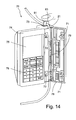
- Figure 14 is a front perspective view of the preferred embodiment of the present invention, a section of tubing, and an occluder, with the door of the present invention opened, and the tubing installed in the pump;
- Figure 15 is a front perspective view of the preferred embodiment of the present invention, a section of tubing, and an occluder, with the door of the present invention open, and the tubing uninstalled from the pump;
- Figure 16 is a front perspective view of the preferred embodiment of the present invention, a section of tubing, and an occluder, with the door of the present invention closed, and the tubing occluded.
-
- It should be appreciated that, in the detailed description of the invention which follows, like reference numbers on different drawing views are intended to identify identical structural elements of the invention in the respective views.
- A first embodiment of the present invention is shown in Figure 1 and generally designated 10.
Apparatus 10 is an infusion pump comprisingpump base 20 withtubing base 31 fixed thereto.Tubing 21 is routed overtubing base 31 underneathocclusion platens platen 25.Occlusion platen 22 is fixed toplaten support 55.Occlusion platen 29 is fixed toplaten support 55.Pump platen 25 comprisesstop platen 26, and is fixed toplaten support 55.Motor 42 is fixed to pumpbase 20.Motor 42drives camshaft 38.Camshaft 38 is supported by shaft supports 40 and 41.Cams camshaft 38. Ascamshaft 38 rotates when driven bymotor 42,cams Cam 35 is operatively arranged to cyclicallydrive occlusion platen 29 between a first, unoccluding position and a second, occluding position. The first position is shown in Figure 1, whereinocclusion platen 29 is not in contact withtubing 21. Ascam 35 is rotated byshaft 38,platen support 55 is driven down bycam 35. This drivesocclusion platen 29 towardstubing 21.Occlusion platen 29 is driven to a second position, shown in Figures 2, 3, and 4, whereocclusion platen 29 occludestubing 21. As the shaft continues to rotate,cam 35 moves away fromplaten support 55.Spring 52, shown on Figures 5 and 6, provides upward force onplaten support 55 to liftocclusion platen 29 back to the first, unoccluded position.Cam 39 drivesocclusion platen 22 through a similar cycle.Occlusion platen 22 is driven from a first, unoccluded position to a second, occluded position. However,occlusion platen 22 occludestubing 21 at substantially different times thanocclusion platen 29.Occlusion platen 22 is shown occludingtubing 21 in Figures 1 and 4.Spring 52, shown on Figures 5 and 6, provides upward force onplaten support 55 to liftocclusion platen 22 back to the first, unoccluded position whencam 39 moves away fromplaten support 55 due to the rotation ofshaft 38. -
Cam 36 drives pumpplaten 25 from a first position to a second position asshaft 38 rotates. The first position is shown in Figures 1, 2, and 4a. The pump platen is not in contact withtubing 21. As shown in Figure 4a, width d ofstop platen 26 is less than width w oftubing 21. Asshaft 38 rotates,cam 36 drives platensupport 55 to a second position, shown in Figures 3, 4, and 4b. In the second position, pumpplaten 25 depressestubing 21. Stopplaten 26 completely collapses a section of the width oftubing 21, as shown in Figure 4b. Stopplaten 26 preventspump platen 25 from occludingtubing 21. Stopplaten 26 does not occludetubing 21 becausestop platen 26 is narrower thantubing 21, as shown in Figure 4a. Occlusion by the pump platen is undesirable because it would require significantly more power than partially occluding the tubing, as shown in Figures 3, 4, and 4b. Further, the tubing does not deform as readily when partially deflected by the pump platen, as compared to the deformation caused by occluding the tubing. - In a preferred embodiment, the platens are spring loaded, to allow the platens to be overdriven. This ensures
tubing 21 is occluded by the occlusion platens or partially occluded by the stop platen, regardless of the dimension oftubing 21. This improves the accuracy of the pump when using tubing of varying dimensions. Otherwise expensive, complicated measurement devices are needed to ensure that the tubing is deflected the appropriate amount by each platen.Springs 51, shown in Figures 5 and 6, accomplish this spring loading. - As shown in Figures 1-4, 1b, 4a, and 4b, the preferred embodiment of
stop platen 26 is a platen that extends the length of the pump platen, and is centered along the width of the pump platen. However, it should be readily apparent to one skilled in the art that many other configurations of stop platens could be used and these modifications are intended to be within the spirit and scope of the invention as claimed. For example, the stop platen could extend only a portion of the length of the pump platen, or it could be located away from the center of the pump platen. A stop platen shorter than the pump platen could be off center along either the length or width of the pump platen, or both. - Figure 1 shows
platen 22 occludingtubing 21, andplatens tubing 21. This is the first position in the pump cycle, which allows fluid from a reservoir (not shown) in flow communication withend 14 oftubing 21 to flow into the tubing proximate the pump platen. Figure 2 showsplaten 29 occludingtubing 21, andplatens tubing 21. This position allows fluid to flow to a patient (not shown) in flow communication withend 12 oftubing 21. Figure 3 showsplaten 29 occludingtubing 21,platen 25 depressingtubing 21 untilstop platen 26 completely collapses the central portion of the width oftubing 21, andplaten 22 abovetubing 21. This configuration forces the fluid intubing 21 towardsend 12 of the tubing. Figure 4 showsplatens tubing 21, andplaten 25 depressingtubing 21 untilstop platen 26 completely collapses the central portion of the width oftubing 21. This is the end of the cycle. Platens 25 and 29 move up again to return to the first configuration of the pump cycle shown in Figure 1. - Figures 1-6 show a
single pump platen 25. However, it should be readily apparent to one skilled in the art that a plurality of pump platens may be used, and these configurations are intended to be within the spirit and scope of the invention as claimed. - Figure 1a is a perspective view of
occlusion platen 29. Figure 1b is a perspective view ofpump platen 25 withstop platen 26 thereon. - Figure 5 is a perspective view of the preferred embodiment of the present invention, designated 50. Figures 1-4
show motor 42 mounted in line withcamshaft 38 so that the platens are visible. To reduce the volume of the pumping assembly, the preferred embodiment locates the motor parallel to the camshaft, coupling them withgears 45 as shown in Figures 5 and 6. It should be readily apparent to one skilled in the art that many mechanical configurations are possible, and these modifications are within the spirit and scope of the invention as claimed. - Figure 6 is an exploded view of the preferred embodiment of the present invention in perspective.
Springs 52 provide an upward force on the platen supports to return them to an upper position when each cam moves away from the platen supports.Springs 52 are connected between the platen supports and thepump base 20.Springs 51 spring load the platens so that they may be overdriven. This enables the pump to be used with tubes of differing dimensions, as discussed above. - Figure 7 is an electrical schematic of the preferred embodiment of the pump.
Circuit 60 shown in Figure 7 is designed to provide power to motor 63 (corresponding tomotor 42 of Figures 1-6) to pump the fluid over a wide range of flow rates at high accuracy. In a preferred embodiment, the pump will deliver 0.1-500 ml/hr ± 2%. This is achieved at a low rate, for example, one revolution per hour, by the following process. N-type field effect transistor (FET) 64 is turned off and P-type FET 61 is turned on, chargingcapacitor 62. P-type FET 61 is then turned off.Capacitor 62 is discharged through motor 63 by turning on N-type FET 64. This discharge process allows a small motor movement. The amount of energy incapacitor 62 is controlled by the amount of time P-type FET 61 is turned on. This process is repeated to pump fluid through the tubing at the desired low rate. - For pumping at a high rate, for example, one revolution per second, P-type FET 61 is turned on and N-type FET 64 pulse width modulates motor 63 with a variable duty cycle. The motor has an average input power based on the duty cycle. The variable power allows higher speed positioning within the tolerances allowed.
Power supply 65 is the battery. In a preferred embodiment,capacitor 62 is a 470 µF capacitor, and resistor 66 is 0.1 ohms. - In the preferred embodiment,
pump assembly 50 is mounted incabinet 70, as shown in Figures 8-16.Cabinet 70 compriseskeyhole 73,case 74,display 75,keypad 76, anddoor 78. Also shown in Figure 8 istubing 21 with anoccluder 80.Occluder 80 has afirst end 81, asecond end 82, and aslit 83. To occludetubing 21,tubing 21 is routed throughslit 83 proximatefirst end 81.Slit 83 is narrowest where the slit is closest to end 81.Slit 83 is wider proximatesecond end 82. Fluid flows freely throughtubing 21 when the tubing is located proximatesecond end 82. Thus,tubing 21 is shown unoccluded in Figure 8. Fluid may flow freely through the tubing to a patient. - Free flow of fluid through the tubing is prevented with the present apparatus as follows. Figure 9 shows
occluder 80 being inserted intoslot 73 of the present invention.Second end 82 must be inserted toopen door 78, asfirst end 81 is too thick to fit intokeyhole 73. Asoccluder 80 is inserted intokeyhole 73,tubing 21 is forced towardsfirst end 81, as shown in Figure 10. Thus to opendoor 79,tubing 21 must be occluded byoccluder 80.Door 78 unlocks as shown in Figure 10, exposing the pump assembly.Door 78 is unlocked when hooks 72disengage loops 71.Tubing 21 is routed alongtubing channel 79, between the tubing base and the platens, as shown in Figure 11.Door 78 is closed, as shown in Figure 12.Occluder 80 is removed fromkeyhole 73, andtubing 21 is moved throughslot 83 until it is unoccluded. This is shown in Figure 13. The pump may now operate to deliver fluid to a patient. - To remove the tubing from
cabinet 70,occluder 80 is again inserted inkeyhole 73. This forcestubing 21 tofirst end 81, occluding the tubing.Door 78 opens, as shown in Figure 14. The tubing is removed from the pump in Figure 15. Figure 16 shows the tubing outside the pump and pumpdoor 78 closed.Tubing 21 is still occluded. In the above-described manner, the present invention requires the tubing to be occluded before the door can be opened. This will prevent medical personnel from forgetting to occlude the tubing before it is removed from the pump.
Claims (24)
- An apparatus for pumping fluid through tubing comprising:a stop platen, said stop platen operatively arranged to depress a wall of said tubing along a section of a longitudinal axis of said tubing, wherein said stop platen is narrower than said tubing along a transverse axis of said tubing; and,actuation means for moving said stop platen to depress said wall of said tubing.
- The apparatus recited in Claim 1 wherein said stop platen is centered with respect to said tubing along said transverse axis of said tubing.
- The apparatus recited in Claim 1 wherein said actuation means comprises a cam fixedly located on a camshaft, said camshaft operatively arranged to be rotated by a motor.
- The apparatus recited in Claim 1 further comprising means to constrain said tubing to remain proximate said stop platen.
- The apparatus recited in Claim 4 wherein said constraining means comprises:a cabinet containing said stop platen;a door rotatably fixed to said cabinet; and,locking means for preventing rotation of said door.
- The apparatus recited in Claim 5 wherein said locking means comprises a latch, said latch operatively arranged to be unlatched by a tubing occluder.
- The apparatus recited in Claim 6 wherein said latch is operatively arranged to be unlatched by a first end of said tubing occluder, wherein said tubing occluder is operatively arranged to occlude said tubing when said tubing is located proximate a second end of said tubing occluder.
- A control circuit for an infusion pump, comprising:a motor operatively arranged to drive said pump;an N-FET transistor having a gate, drain and source, said N-FET transistor arranged in series with said motor;a P-FET transistor having a gate, drain and source, said P-FET transistor arranged in series with said motor; and,a capacitor operatively arranged to store energy to drive said motor, said capacitor arranged in parallel with said motor, said capacitor having a first lead and a second lead, said first lead connected to a node connecting the drain of said P-FET transistor and a lead from said motor, and said second lead connected to the source of said N-FET transistor.
- The control circuit recited in Claim 8 wherein said N-FET transistor is operatively arranged to be turned off when said P-FET transistor is operatively arranged to be turned on to charge said capacitor, and, subsequently, said N-FET transistor is operatively arranged to be turned on and said P-FET transistor is operatively arranged to be turned off to drive said motor at a relatively low rate of speed.
- The control circuit recited in Claim 9 wherein said relatively low rate of speed is in the range of 1-10 revolutions per hour.
- The control circuit recited in Claim 8 wherein said motor is driven at a rate of speed in the range of 1 revolution per hour to 1 revolution per second.
- The control circuit recited in Claim 8 wherein said P-FET transistor is operatively arranged to be turned on while said N-FET transistor is operatively arranged to drive said motor with pulse width modulation at a relatively high rate of speed.
- The control circuit recited in Claim 12 wherein said relatively high rate of speed is at least 1 revolution per second.
- The control circuit recited in Claim 12 wherein said relatively high rate of speed approximates 1 revolution per second.
- An apparatus for preventing the free flow of fluid in tubing installed in a pump comprising:a cabinet containing said pump;a door rotatably fixed to said cabinet; and,locking means for preventing rotation of said door, said means operatively arranged to be unlocked by a tubing occluder.
- The apparatus recited in Claim 15 wherein said locking means comprises a latch, said latch operatively arranged to be unlatched by a first end of said tubing occluder, wherein said tubing occluder is operatively arranged to occlude said tubing when said tubing is located proximate a second end of said tubing occluder.
- A method for pumping fluid through tubing with a first end and a second end comprising:occluding said tubing at a first location, said first location between said pump and said first end of said tubing;delivering said fluid into said tubing from a reservoir in flow communication with said second end of said tubing;occluding said tubing at a second location, said second location between said reservoir and said pump;unoccluding said tubing at said first location; and,depressing a longitudinal section of said tubing with a stop platen of said pump that is narrower than said tubing along a transverse axis of said tubing.
- The method recited in Claim 17 wherein said stop platen is centered with respect to said tubing in a transverse direction.
- A method for installing tubing into an infusion comprising:occluding said tubing with an occluder with a first end and a second end, wherein said tubing is occluded when said tubing is proximate said first end;inserting said second end of said occluder into said infusion pump to unlock a door of said pump;installing said occluded tubing in said pump; and,locking said door.
- A method for removing tubing from an infusion pump comprising:occluding said tubing with an occluder with a first end and a second end, wherein said tubing is occluded when said tubing is proximate said first end;inserting said second end of said occluder into said infusion pump to release said tubing from constraining means of said pump; and,removing said occluded tubing from said pump.
- The method recited in Claim 20 wherein said constraining means comprises a door operatively arranged to prevent the removal of said tubing from said pump when said door is closed.
- An improvement to an infusion pump comprising:a stop platen, said stop platen operatively arranged to depress a wall of said tubing along a section of a longitudinal axis of said tubing, wherein said stop platen is narrower than said tubing along a transverse axis of said tubing.
- A method for unlocking a door of an infusion pump comprising:inserting a portion of an occluder into said infusion pump to unlock a door of said pump.
- An improvement to a method for pumping fluid through tubing comprising:depressing a longitudinal section of said tubing with a stop platen that is narrower than said tubing along a transverse axis of said tubing.
Applications Claiming Priority (2)
| Application Number | Priority Date | Filing Date | Title |
|---|---|---|---|
| US10/117,515 US7059840B2 (en) | 2002-04-05 | 2002-04-05 | Energy-saving, anti-free flow portable pump for use with standard PVC IV tubing |
| US117515 | 2002-04-05 |
Publications (3)
| Publication Number | Publication Date |
|---|---|
| EP1350955A2 true EP1350955A2 (en) | 2003-10-08 |
| EP1350955A3 EP1350955A3 (en) | 2004-04-14 |
| EP1350955B1 EP1350955B1 (en) | 2011-10-05 |
Family
ID=28041105
Family Applications (1)
| Application Number | Title | Priority Date | Filing Date |
|---|---|---|---|
| EP03007783A Expired - Fee Related EP1350955B1 (en) | 2002-04-05 | 2003-04-04 | Peristaltic pump |
Country Status (2)
| Country | Link |
|---|---|
| US (2) | US7059840B2 (en) |
| EP (1) | EP1350955B1 (en) |
Cited By (12)
| Publication number | Priority date | Publication date | Assignee | Title |
|---|---|---|---|---|
| WO2008038326A3 (en) * | 2006-09-26 | 2008-05-15 | Marina Anna Brivio | Peristaltic pump |
| US8678793B2 (en) | 2004-11-24 | 2014-03-25 | Q-Core Medical Ltd. | Finger-type peristaltic pump |
| US8920144B2 (en) | 2009-12-22 | 2014-12-30 | Q-Core Medical Ltd. | Peristaltic pump with linear flow control |
| US9056160B2 (en) | 2006-11-13 | 2015-06-16 | Q-Core Medical Ltd | Magnetically balanced finger-type peristaltic pump |
| US9333290B2 (en) | 2006-11-13 | 2016-05-10 | Q-Core Medical Ltd. | Anti-free flow mechanism |
| US9457158B2 (en) | 2010-04-12 | 2016-10-04 | Q-Core Medical Ltd. | Air trap for intravenous pump |
| US9657902B2 (en) | 2004-11-24 | 2017-05-23 | Q-Core Medical Ltd. | Peristaltic infusion pump with locking mechanism |
| US9674811B2 (en) | 2011-01-16 | 2017-06-06 | Q-Core Medical Ltd. | Methods, apparatus and systems for medical device communication, control and localization |
| US9726167B2 (en) | 2011-06-27 | 2017-08-08 | Q-Core Medical Ltd. | Methods, circuits, devices, apparatuses, encasements and systems for identifying if a medical infusion system is decalibrated |
| US9855110B2 (en) | 2013-02-05 | 2018-01-02 | Q-Core Medical Ltd. | Methods, apparatus and systems for operating a medical device including an accelerometer |
| US10113543B2 (en) | 2006-11-13 | 2018-10-30 | Q-Core Medical Ltd. | Finger type peristaltic pump comprising a ribbed anvil |
| US11679189B2 (en) | 2019-11-18 | 2023-06-20 | Eitan Medical Ltd. | Fast test for medical pump |
Families Citing this family (23)
| Publication number | Priority date | Publication date | Assignee | Title |
|---|---|---|---|---|
| FR2872554B1 (en) * | 2004-06-30 | 2008-09-19 | Millipore Corp | PERISTALTIC PUMP COMPRISING TUBE POSITIONING BODIES |
| ITBO20050203A1 (en) * | 2005-03-30 | 2006-09-30 | Medical Service S R L | DISPOSABLE MODULE, PERISTALTIC PUMP, EQUIPMENT FOR BLOOD TREATMENT AND SYSTEM CONSISTING OF THE ASSOCIATION OF THE DISPOSABLE MODULE AND OF THE EQUIPMENT |
| US8303275B2 (en) * | 2006-12-07 | 2012-11-06 | Seiko Epson Corporation | Micropump, tube unit, and control unit |
| JP5298699B2 (en) | 2008-08-20 | 2013-09-25 | セイコーエプソン株式会社 | Control unit, tube unit, micro pump |
| JP5282508B2 (en) | 2008-09-29 | 2013-09-04 | セイコーエプソン株式会社 | Control unit, tube unit, micro pump |
| JP5195368B2 (en) | 2008-12-05 | 2013-05-08 | セイコーエプソン株式会社 | Tube unit, control unit, micro pump |
| US8545451B2 (en) | 2009-03-30 | 2013-10-01 | Lifemedix Statfusion, Llc | Manual pump for intravenous fluids |
| US8337466B2 (en) * | 2009-03-30 | 2012-12-25 | Lifemedix, Llc | Manual pump for intravenous fluids |
| US9677555B2 (en) | 2011-12-21 | 2017-06-13 | Deka Products Limited Partnership | System, method, and apparatus for infusing fluid |
| WO2012112920A1 (en) | 2011-02-19 | 2012-08-23 | Shipman Douglas | Improved pump, method of operation, and method of manufacture |
| US11295846B2 (en) | 2011-12-21 | 2022-04-05 | Deka Products Limited Partnership | System, method, and apparatus for infusing fluid |
| US9675756B2 (en) | 2011-12-21 | 2017-06-13 | Deka Products Limited Partnership | Apparatus for infusing fluid |
| CN112138240B (en) * | 2012-05-24 | 2023-04-07 | 德卡产品有限公司 | Device for infusing fluid |
| WO2016044146A2 (en) | 2014-09-18 | 2016-03-24 | Deka Products Limited Partnership | Apparatus and method for infusing fluid through a tube by appropriately heating the tube |
| CA3062798A1 (en) | 2017-05-09 | 2018-11-15 | Baxter International Inc. | Parenteral nutrition diagnostic system, apparatus, and method |
| MX2020012007A (en) | 2018-05-11 | 2021-02-09 | Baxter Int | Medical device data back-association, system, apparatuses, and methods. |
| KR20210042378A (en) | 2018-08-16 | 2021-04-19 | 데카 프로덕츠 리미티드 파트너쉽 | Medical pump |
| IL273061B2 (en) | 2019-03-04 | 2024-01-01 | Avoset Health Ltd | In cycle pressure measurement |
| EP3934716A1 (en) | 2019-03-05 | 2022-01-12 | Eitan Medical Ltd. | Anti-free-flow valve |
| US11426515B2 (en) | 2019-07-25 | 2022-08-30 | Zevex, Inc. | Infusion pump cassette having integrated pinch clip occluder |
| US11446431B2 (en) | 2019-11-14 | 2022-09-20 | Zevex, Inc. | Infusion pump apparatus having convex platen surface |
| US20220054742A1 (en) * | 2020-08-24 | 2022-02-24 | Modular Medical, Inc. | Portable infusion pump with pinch/squeeze pumping action |
| WO2023129948A1 (en) | 2021-12-30 | 2023-07-06 | Baxter International Inc. | Pump interconnectivity for pain medication therapies |
Family Cites Families (50)
| Publication number | Priority date | Publication date | Assignee | Title |
|---|---|---|---|---|
| US1765360A (en) * | 1926-02-18 | 1930-06-24 | Bbc Brown Boveri & Cie | Rotary pump |
| US2406485A (en) * | 1944-05-05 | 1946-08-27 | Univ Tennessee Res Corp | Hose pump |
| US2987004A (en) * | 1955-07-29 | 1961-06-06 | Jerome L Murray | Fluid pressure device |
| US3295556A (en) * | 1963-08-26 | 1967-01-03 | Laurence W Gertsma | Foldable conduit |
| FR1401317A (en) | 1964-04-20 | 1965-06-04 | Alsacienne De Construction D A | Pump |
| US3875970A (en) * | 1971-03-25 | 1975-04-08 | Manostat Corp | Tubing |
| AT337005B (en) * | 1974-04-24 | 1977-06-10 | Sermem Sa | DOSING HOSE PUMP |
| FR2317526A1 (en) * | 1975-07-08 | 1977-02-04 | Rhone Poulenc Ind | PERISTALTIC PUMP |
| US4653987A (en) | 1984-07-06 | 1987-03-31 | Tsuyoshi Tsuji | Finger peristaltic infusion pump |
| US4559038A (en) * | 1984-10-19 | 1985-12-17 | Deltec Systems, Inc. | Drug delivery system |
| US4688753A (en) * | 1984-12-06 | 1987-08-25 | Baxter Travenol Laboratories, Inc. | Tubing occluder |
| US4616802A (en) * | 1984-12-06 | 1986-10-14 | Baxter Travenol Laboratories, Inc. | Tubing occluder |
| US4586882A (en) * | 1984-12-06 | 1986-05-06 | Baxter Travenol Laboratories, Inc. | Tubing occluder pump |
| JPS61228872A (en) * | 1985-04-01 | 1986-10-13 | シャープ株式会社 | Liquid drug injection apparatus |
| US5074756A (en) * | 1988-05-17 | 1991-12-24 | Patient Solutions, Inc. | Infusion device with disposable elements |
| GB8825816D0 (en) * | 1988-11-04 | 1988-12-07 | Danby Medical Eng Ltd | Pumping device |
| US4954055A (en) * | 1989-06-22 | 1990-09-04 | Baxter International, Inc. | Variable roller pump tubing |
| US4932629A (en) * | 1989-09-18 | 1990-06-12 | Nova Biomedical Corporation | Clamp for flexible tubing |
| US5215450A (en) * | 1991-03-14 | 1993-06-01 | Yehuda Tamari | Innovative pumping system for peristaltic pumps |
| US5033943A (en) * | 1990-01-08 | 1991-07-23 | Eldex Laboratories, Inc. | Low fluid shear pump |
| US5055001A (en) * | 1990-03-15 | 1991-10-08 | Abbott Laboratories | Volumetric pump with spring-biased cracking valves |
| JPH04101087A (en) * | 1990-08-13 | 1992-04-02 | Asahi Okuma Ind Co Ltd | Tube for tube pump |
| US5067879A (en) * | 1990-09-18 | 1991-11-26 | Carpenter Walter L | Peristaltic pump system |
| US5082025A (en) * | 1990-11-23 | 1992-01-21 | Dlp, Inc. | Antegrade-retrograde switch and occluder and system for using the same |
| US5281112A (en) * | 1992-02-25 | 1994-01-25 | The Regents Of The University Of Michigan | Self regulating blood pump with controlled suction |
| US5286176A (en) * | 1993-05-06 | 1994-02-15 | The United States Of America As Represented By The Secretary Of The Navy | Electromagnetic pump |
| US5817083A (en) * | 1993-05-31 | 1998-10-06 | Migda Inc. | Mixing device and clamps useful therein |
| US5772409A (en) | 1993-11-22 | 1998-06-30 | Sims Deltec, Inc. | Drug infusion device with pressure plate |
| GB9405523D0 (en) | 1994-03-21 | 1994-05-04 | Graseby Medical Ltd | Pumping and pressure detection using flexible tubes |
| US5695473A (en) * | 1994-07-27 | 1997-12-09 | Sims Deltec, Inc. | Occlusion detection system for an infusion pump |
| US5567120A (en) | 1994-10-13 | 1996-10-22 | Sigma International | Electronic infusion device and novel roller clamp holden therefor |
| US6234773B1 (en) * | 1994-12-06 | 2001-05-22 | B-Braun Medical, Inc. | Linear peristaltic pump with reshaping fingers interdigitated with pumping elements |
| JP3749277B2 (en) * | 1995-01-18 | 2006-02-22 | アラリス メディカル システムズ インコーポレイテッド | Infusion pump |
| US5628619A (en) | 1995-03-06 | 1997-05-13 | Sabratek Corporation | Infusion pump having power-saving modes |
| US5674052A (en) * | 1995-11-14 | 1997-10-07 | Coulter International Corp. | Pinch pump having selectable pressure plate sizes and a flexible tube with attachment ribs |
| JP3698277B2 (en) | 1995-11-28 | 2005-09-21 | テルモ株式会社 | Infusion pump |
| US5924852A (en) * | 1996-03-12 | 1999-07-20 | Moubayed; Ahmad-Maher | Linear peristaltic pump |
| US5791881A (en) * | 1996-10-18 | 1998-08-11 | Moubayed; Ahmad-Maher | Curvilinear peristaltic pump with occlusion detection means |
| GR1002892B (en) * | 1997-02-17 | 1998-04-10 | Micrel | Linear peristaltic pump |
| US5868712A (en) * | 1997-06-12 | 1999-02-09 | Abbott Laboratories | Pump with door-mounted mechanism for positioning tubing in the pump housing |
| AU742895B2 (en) * | 1997-07-03 | 2002-01-17 | Precision Dispensing Systems Limited | A flexible tube pinch mechanism |
| US6036166A (en) * | 1997-09-25 | 2000-03-14 | Imi Cornelius Inc. | Chamber valve |
| US5964583A (en) * | 1997-10-15 | 1999-10-12 | Baxter International Inc. | Elastomerically assisted peristaltic pump |
| US5853398A (en) * | 1997-12-19 | 1998-12-29 | Baxter International Inc. | Container with pivoting tube clamp |
| US6267559B1 (en) | 1999-12-21 | 2001-07-31 | Alaris Medical Systems, Inc. | Apparatus and method for reducing power consumption in a peristaltic pump mechanism |
| DE20003059U1 (en) | 2000-02-19 | 2001-06-28 | Braun Melsungen Ag | Peristaltic pump |
| US20030138335A1 (en) * | 2000-07-03 | 2003-07-24 | Yutaka Doi | Tube pump |
| IL141137A0 (en) * | 2001-01-28 | 2002-02-10 | Caesaria Med Electronics Ltd | Liquid pump |
| US6942473B2 (en) * | 2002-03-21 | 2005-09-13 | Hospira, Inc. | Pump and tube set thereof |
| US6731216B2 (en) * | 2002-05-20 | 2004-05-04 | B. Braun Medical, Inc. | Proper tubing installation testing method and apparatus for a peristaltic pump |
-
2002
- 2002-04-05 US US10/117,515 patent/US7059840B2/en not_active Expired - Lifetime
-
2003
- 2003-04-04 EP EP03007783A patent/EP1350955B1/en not_active Expired - Fee Related
-
2005
- 2005-05-17 US US11/131,058 patent/US20050214146A1/en not_active Abandoned
Non-Patent Citations (1)
| Title |
|---|
| None |
Cited By (16)
| Publication number | Priority date | Publication date | Assignee | Title |
|---|---|---|---|---|
| US9404490B2 (en) | 2004-11-24 | 2016-08-02 | Q-Core Medical Ltd. | Finger-type peristaltic pump |
| US8678793B2 (en) | 2004-11-24 | 2014-03-25 | Q-Core Medical Ltd. | Finger-type peristaltic pump |
| US10184615B2 (en) | 2004-11-24 | 2019-01-22 | Q-Core Medical Ltd. | Peristaltic infusion pump with locking mechanism |
| US9657902B2 (en) | 2004-11-24 | 2017-05-23 | Q-Core Medical Ltd. | Peristaltic infusion pump with locking mechanism |
| US8408887B2 (en) | 2006-09-26 | 2013-04-02 | Hemodec S.R.L. | Peristaltic pump |
| WO2008038326A3 (en) * | 2006-09-26 | 2008-05-15 | Marina Anna Brivio | Peristaltic pump |
| US9581152B2 (en) | 2006-11-13 | 2017-02-28 | Q-Core Medical Ltd. | Magnetically balanced finger-type peristaltic pump |
| US9333290B2 (en) | 2006-11-13 | 2016-05-10 | Q-Core Medical Ltd. | Anti-free flow mechanism |
| US9056160B2 (en) | 2006-11-13 | 2015-06-16 | Q-Core Medical Ltd | Magnetically balanced finger-type peristaltic pump |
| US10113543B2 (en) | 2006-11-13 | 2018-10-30 | Q-Core Medical Ltd. | Finger type peristaltic pump comprising a ribbed anvil |
| US8920144B2 (en) | 2009-12-22 | 2014-12-30 | Q-Core Medical Ltd. | Peristaltic pump with linear flow control |
| US9457158B2 (en) | 2010-04-12 | 2016-10-04 | Q-Core Medical Ltd. | Air trap for intravenous pump |
| US9674811B2 (en) | 2011-01-16 | 2017-06-06 | Q-Core Medical Ltd. | Methods, apparatus and systems for medical device communication, control and localization |
| US9726167B2 (en) | 2011-06-27 | 2017-08-08 | Q-Core Medical Ltd. | Methods, circuits, devices, apparatuses, encasements and systems for identifying if a medical infusion system is decalibrated |
| US9855110B2 (en) | 2013-02-05 | 2018-01-02 | Q-Core Medical Ltd. | Methods, apparatus and systems for operating a medical device including an accelerometer |
| US11679189B2 (en) | 2019-11-18 | 2023-06-20 | Eitan Medical Ltd. | Fast test for medical pump |
Also Published As
| Publication number | Publication date |
|---|---|
| EP1350955B1 (en) | 2011-10-05 |
| EP1350955A3 (en) | 2004-04-14 |
| US20050214146A1 (en) | 2005-09-29 |
| US20030190246A1 (en) | 2003-10-09 |
| US7059840B2 (en) | 2006-06-13 |
Similar Documents
| Publication | Publication Date | Title |
|---|---|---|
| EP1350955A2 (en) | Peristaltic pump | |
| US5131816A (en) | Cartridge fed programmable ambulatory infusion pumps powered by DC electric motors | |
| EP0813430B1 (en) | Cassette for an infusion pump | |
| US10888653B2 (en) | Feeding set with cassette and related methods therefor | |
| US4391600A (en) | Nonpulsating IV pump and disposable pump chamber | |
| US4410322A (en) | Nonpulsating TV pump and disposable pump chamber | |
| EP0090440B1 (en) | Nonpulsating intravenous pump | |
| EP1485149B1 (en) | Tube set for a pump | |
| CN1938061B (en) | Actuator system comprising detector means | |
| CN100586495C (en) | Actuator system comprising lever mechanism | |
| CA2038840C (en) | Infusion pump with dual position syringe locator | |
| US20020151846A1 (en) | Implantable drug delivery device with peristaltic pump having retracting roller | |
| HUE030577T2 (en) | System and methods for medicament infusion | |
| WO1991016933A1 (en) | Disposable infusion apparatus with peristaltic pump | |
| US20070048153A1 (en) | Thin and Foldable Fluid Pump Carried under User's Clothes | |
| WO2003081046A2 (en) | Pump and tube set thereof | |
| EP3810223B1 (en) | Cassette for a flow control apparatus | |
| CA1148824A (en) | Medical infusion system and method of operation |
Legal Events
| Date | Code | Title | Description |
|---|---|---|---|
| PUAI | Public reference made under article 153(3) epc to a published international application that has entered the european phase |
Free format text: ORIGINAL CODE: 0009012 |
|
| AK | Designated contracting states |
Kind code of ref document: A2 Designated state(s): AT BE BG CH CY CZ DE DK EE ES FI FR GB GR HU IE IT LI LU MC NL PT RO SE SI SK TR |
|
| AX | Request for extension of the european patent |
Extension state: AL LT LV MK |
|
| PUAL | Search report despatched |
Free format text: ORIGINAL CODE: 0009013 |
|
| AK | Designated contracting states |
Kind code of ref document: A3 Designated state(s): AT BE BG CH CY CZ DE DK EE ES FI FR GB GR HU IE IT LI LU MC NL PT RO SE SI SK TR |
|
| AX | Request for extension of the european patent |
Extension state: AL LT LV MK |
|
| 17P | Request for examination filed |
Effective date: 20041009 |
|
| AKX | Designation fees paid |
Designated state(s): DE FR GB IT |
|
| 17Q | First examination report despatched |
Effective date: 20081111 |
|
| GRAJ | Information related to disapproval of communication of intention to grant by the applicant or resumption of examination proceedings by the epo deleted |
Free format text: ORIGINAL CODE: EPIDOSDIGR1 |
|
| GRAP | Despatch of communication of intention to grant a patent |
Free format text: ORIGINAL CODE: EPIDOSNIGR1 |
|
| GRAS | Grant fee paid |
Free format text: ORIGINAL CODE: EPIDOSNIGR3 |
|
| GRAA | (expected) grant |
Free format text: ORIGINAL CODE: 0009210 |
|
| RAP1 | Party data changed (applicant data changed or rights of an application transferred) |
Owner name: SIGMA INTERNATIONAL GENERAL MEDICAL APPARATUS, LLC |
|
| AK | Designated contracting states |
Kind code of ref document: B1 Designated state(s): DE FR GB IT |
|
| REG | Reference to a national code |
Ref country code: GB Ref legal event code: FG4D |
|
| REG | Reference to a national code |
Ref country code: DE Ref legal event code: R096 Ref document number: 60338583 Country of ref document: DE Effective date: 20111201 |
|
| PLBE | No opposition filed within time limit |
Free format text: ORIGINAL CODE: 0009261 |
|
| STAA | Information on the status of an ep patent application or granted ep patent |
Free format text: STATUS: NO OPPOSITION FILED WITHIN TIME LIMIT |
|
| 26N | No opposition filed |
Effective date: 20120706 |
|
| REG | Reference to a national code |
Ref country code: DE Ref legal event code: R097 Ref document number: 60338583 Country of ref document: DE Effective date: 20120706 |
|
| REG | Reference to a national code |
Ref country code: DE Ref legal event code: R082 Ref document number: 60338583 Country of ref document: DE Representative=s name: REICHERT & KOLLEGEN, DE |
|
| REG | Reference to a national code |
Ref country code: DE Ref legal event code: R082 Ref document number: 60338583 Country of ref document: DE Representative=s name: REICHERT & LINDNER PARTNERSCHAFT PATENTANWAELT, DE Effective date: 20130206 Ref country code: DE Ref legal event code: R081 Ref document number: 60338583 Country of ref document: DE Owner name: BAXTER INTERNATIONAL INC., DEERFIELD, US Free format text: FORMER OWNER: SIGMA INTERNATIONAL GENERAL MEDICAL APPARATUS, LLC, MEDINA, N.Y., US Effective date: 20130206 Ref country code: DE Ref legal event code: R081 Ref document number: 60338583 Country of ref document: DE Owner name: BAXTER INTERNATIONAL INC., DEERFIELD, US Free format text: FORMER OWNER: SIGMA INTERNATIONAL, MEDINA, N.Y., US Effective date: 20111011 Ref country code: DE Ref legal event code: R081 Ref document number: 60338583 Country of ref document: DE Owner name: BAXTER HEALTHCARE S.A., CH Free format text: FORMER OWNER: SIGMA INTERNATIONAL GENERAL MEDICAL APPARATUS, LLC, MEDINA, N.Y., US Effective date: 20130206 Ref country code: DE Ref legal event code: R081 Ref document number: 60338583 Country of ref document: DE Owner name: BAXTER HEALTHCARE S.A., CH Free format text: FORMER OWNER: SIGMA INTERNATIONAL, MEDINA, N.Y., US Effective date: 20111011 Ref country code: DE Ref legal event code: R082 Ref document number: 60338583 Country of ref document: DE Representative=s name: REICHERT & KOLLEGEN, DE Effective date: 20130206 Ref country code: DE Ref legal event code: R081 Ref document number: 60338583 Country of ref document: DE Owner name: BAXTER HEALTHCARE S.A., CH Free format text: FORMER OWNER: SIGMA INTERNATIONAL, MEDINA, US Effective date: 20111011 Ref country code: DE Ref legal event code: R081 Ref document number: 60338583 Country of ref document: DE Owner name: BAXTER HEALTHCARE S.A., CH Free format text: FORMER OWNER: SIGMA INTERNATIONAL GENERAL MEDICAL APPARATUS, LLC, MEDINA, US Effective date: 20130206 Ref country code: DE Ref legal event code: R081 Ref document number: 60338583 Country of ref document: DE Owner name: BAXTER INTERNATIONAL INC., US Free format text: FORMER OWNER: SIGMA INTERNATIONAL GENERAL MEDICAL APPARATUS, LLC, MEDINA, US Effective date: 20130206 Ref country code: DE Ref legal event code: R081 Ref document number: 60338583 Country of ref document: DE Owner name: BAXTER INTERNATIONAL INC., US Free format text: FORMER OWNER: SIGMA INTERNATIONAL, MEDINA, US Effective date: 20111011 |
|
| REG | Reference to a national code |
Ref country code: GB Ref legal event code: 732E Free format text: REGISTERED BETWEEN 20130321 AND 20130327 |
|
| REG | Reference to a national code |
Ref country code: FR Ref legal event code: TQ Owner name: BAXTER INTERNATIONAL INC., US Effective date: 20130321 Ref country code: FR Ref legal event code: TQ Owner name: BAXTER HEALTHCARE SA, CH Effective date: 20130321 |
|
| REG | Reference to a national code |
Ref country code: FR Ref legal event code: PLFP Year of fee payment: 13 |
|
| REG | Reference to a national code |
Ref country code: DE Ref legal event code: R082 Ref document number: 60338583 Country of ref document: DE Representative=s name: REICHERT & LINDNER PARTNERSCHAFT PATENTANWAELT, DE |
|
| REG | Reference to a national code |
Ref country code: FR Ref legal event code: PLFP Year of fee payment: 14 |
|
| REG | Reference to a national code |
Ref country code: FR Ref legal event code: PLFP Year of fee payment: 15 |
|
| REG | Reference to a national code |
Ref country code: FR Ref legal event code: PLFP Year of fee payment: 16 |
|
| PGFP | Annual fee paid to national office [announced via postgrant information from national office to epo] |
Ref country code: DE Payment date: 20180321 Year of fee payment: 16 |
|
| PGFP | Annual fee paid to national office [announced via postgrant information from national office to epo] |
Ref country code: IT Payment date: 20180327 Year of fee payment: 16 Ref country code: FR Payment date: 20180420 Year of fee payment: 16 |
|
| PGFP | Annual fee paid to national office [announced via postgrant information from national office to epo] |
Ref country code: GB Payment date: 20180420 Year of fee payment: 16 |
|
| REG | Reference to a national code |
Ref country code: DE Ref legal event code: R119 Ref document number: 60338583 Country of ref document: DE |
|
| GBPC | Gb: european patent ceased through non-payment of renewal fee |
Effective date: 20190404 |
|
| PG25 | Lapsed in a contracting state [announced via postgrant information from national office to epo] |
Ref country code: DE Free format text: LAPSE BECAUSE OF NON-PAYMENT OF DUE FEES Effective date: 20191101 Ref country code: GB Free format text: LAPSE BECAUSE OF NON-PAYMENT OF DUE FEES Effective date: 20190404 |
|
| PG25 | Lapsed in a contracting state [announced via postgrant information from national office to epo] |
Ref country code: IT Free format text: LAPSE BECAUSE OF NON-PAYMENT OF DUE FEES Effective date: 20190404 |
|
| PG25 | Lapsed in a contracting state [announced via postgrant information from national office to epo] |
Ref country code: FR Free format text: LAPSE BECAUSE OF NON-PAYMENT OF DUE FEES Effective date: 20190430 |