EP1350457A2 - Domestic vacuum cleaner comprising a dust bag, and set of dust bags - Google Patents
Domestic vacuum cleaner comprising a dust bag, and set of dust bags Download PDFInfo
- Publication number
- EP1350457A2 EP1350457A2 EP03006333A EP03006333A EP1350457A2 EP 1350457 A2 EP1350457 A2 EP 1350457A2 EP 03006333 A EP03006333 A EP 03006333A EP 03006333 A EP03006333 A EP 03006333A EP 1350457 A2 EP1350457 A2 EP 1350457A2
- Authority
- EP
- European Patent Office
- Prior art keywords
- filter bag
- vacuum cleaner
- filter
- layer
- bag
- Prior art date
- Legal status (The legal status is an assumption and is not a legal conclusion. Google has not performed a legal analysis and makes no representation as to the accuracy of the status listed.)
- Pending
Links
Images

Classifications
-
- A—HUMAN NECESSITIES
- A47—FURNITURE; DOMESTIC ARTICLES OR APPLIANCES; COFFEE MILLS; SPICE MILLS; SUCTION CLEANERS IN GENERAL
- A47L—DOMESTIC WASHING OR CLEANING; SUCTION CLEANERS IN GENERAL
- A47L9/00—Details or accessories of suction cleaners, e.g. mechanical means for controlling the suction or for effecting pulsating action; Storing devices specially adapted to suction cleaners or parts thereof; Carrying-vehicles specially adapted for suction cleaners
- A47L9/10—Filters; Dust separators; Dust removal; Automatic exchange of filters
- A47L9/14—Bags or the like; Rigid filtering receptacles; Attachment of, or closures for, bags or receptacles
-
- A—HUMAN NECESSITIES
- A47—FURNITURE; DOMESTIC ARTICLES OR APPLIANCES; COFFEE MILLS; SPICE MILLS; SUCTION CLEANERS IN GENERAL
- A47L—DOMESTIC WASHING OR CLEANING; SUCTION CLEANERS IN GENERAL
- A47L7/00—Suction cleaners adapted for additional purposes; Tables with suction openings for cleaning purposes; Containers for cleaning articles by suction; Suction cleaners adapted to cleaning of brushes; Suction cleaners adapted to taking-up liquids
- A47L7/04—Suction cleaners adapted for additional purposes; Tables with suction openings for cleaning purposes; Containers for cleaning articles by suction; Suction cleaners adapted to cleaning of brushes; Suction cleaners adapted to taking-up liquids for using the exhaust air for other purposes, e.g. for distribution of chemicals in a room, for sterilisation of the air
-
- A—HUMAN NECESSITIES
- A47—FURNITURE; DOMESTIC ARTICLES OR APPLIANCES; COFFEE MILLS; SPICE MILLS; SUCTION CLEANERS IN GENERAL
- A47L—DOMESTIC WASHING OR CLEANING; SUCTION CLEANERS IN GENERAL
- A47L9/00—Details or accessories of suction cleaners, e.g. mechanical means for controlling the suction or for effecting pulsating action; Storing devices specially adapted to suction cleaners or parts thereof; Carrying-vehicles specially adapted for suction cleaners
- A47L9/10—Filters; Dust separators; Dust removal; Automatic exchange of filters
- A47L9/14—Bags or the like; Rigid filtering receptacles; Attachment of, or closures for, bags or receptacles
- A47L9/1409—Rigid filtering receptacles
-
- B—PERFORMING OPERATIONS; TRANSPORTING
- B01—PHYSICAL OR CHEMICAL PROCESSES OR APPARATUS IN GENERAL
- B01D—SEPARATION
- B01D39/00—Filtering material for liquid or gaseous fluids
- B01D39/14—Other self-supporting filtering material ; Other filtering material
- B01D39/16—Other self-supporting filtering material ; Other filtering material of organic material, e.g. synthetic fibres
- B01D39/1607—Other self-supporting filtering material ; Other filtering material of organic material, e.g. synthetic fibres the material being fibrous
- B01D39/1623—Other self-supporting filtering material ; Other filtering material of organic material, e.g. synthetic fibres the material being fibrous of synthetic origin
Definitions
- the invention first relates to a household vacuum cleaner with an electric motor and a multi-layer, air-permeable arranged on the vacuum cleaner and after filling, filter bags designed for disposal Absorbing dirt, whereby the electric motor is a suction fan drives, which on the one hand sucks the dirt through a vacuum cleaner nozzle and on the other hand blows the dirt into the filter bag.
- the electric motor is a suction fan drives, which on the one hand sucks the dirt through a vacuum cleaner nozzle and on the other hand blows the dirt into the filter bag.
- Household vacuum cleaners of the type in question are known. These point to fix and hold the filter bag a rigid or textile Filter bag chamber. To meet hygiene and allergy claims to become known, it is further known in the air flow path of the vacuum cleaner In addition to the filter bag, additional filter elements at various points in the Arrange device.
- a loose arrangement is preferred of activated carbon granules in the filter bag.
- the content of this patent application is hereby incorporated fully included in the disclosure of the present invention, too for the purpose of features of this patent application in claims of this Include invention.
- the adsorbent can directly in the Dust collection space of the filter bag in loose form or in its own, air-permeable casing can be arranged.
- activated carbon fibers with a fiber diameter of 0.01 to 0.1 mm and a fiber length from 10 to 100 mm or activated carbon powder with a grain size fraction between 0.15 and 0.25 preferred.
- the inventive exposed arrangement of the filter bag on the vacuum cleaner the advantage of a level control that is easier for the user.
- the filter bag has a holding plate, provided that the holding plate is a plastic plate is. This has the necessary stability for the direct connection of the filter bag on the vacuum cleaner or on its motor housing. So the determination the filter bag in the simplest way by a clamp on the motor housing reached which clamp holder acts on the holding plate. It is also proposed that all layers of the filter bag are at least partially consist of plastic fibers. A combination with one is also possible Paper Liner. As a result, the bag can preferably be made from Plastic-made mounting plate to be welded.
- the advantageous effect has the advantageous effect that a partial melting results in a Arrest of the layers among themselves is achieved so that the self-supporting trained position of the filter bag carries the other layers and thus the Filter bag holds in a predetermined shape.
- the plastic fibers can For example, melt blown, spit fiber or bicomponent fibers that are thermally, are chemically or mechanically cross-linked.
- the single ones Layers can also be laminated together. Because of this, that by the inventive design of the filter bag and its direct, exposed arrangement on the vacuum cleaner receiving it Filter chamber is omitted, a further advantageous effect results from the Vacuum cleaner thanks to different sized filter bags in its outer contour can be designed differently. So in the simplest possible way the circumstances different filter bag sizes can be arranged.
- the third layer can be, for example, a fine fiber fleece, such as an electrostatically charged one Melt blown fleece.
- The, the mechanical strength and thus the outermost layer forming the support layer is further preferred in Spun bond process produced to form a spunbond.
- this support layer of the filter bag elastically, so that the filter bag outer contour is adaptable to the recorded one Dust / debris volumes. Since according to the invention the filter bag is terminal, it is the last link in a possible filter chain, that the filter bag of one HEPA class is sufficient, at least H10, better H11 or H12, more preferably H13.
- the filter bag a degree of separation of more than 85%, preferably more than 95%, more preferably more than 99.5%, more preferably more than 99.95% based on the MPPS (Most Penetrating Particle Size) according to the standard EN 1822 has.
- the invention further relates to a set of filter bags for a specific one Household vacuum cleaner type.
- a set can be two, three, four, five or more different contain large filter bags for the same household vacuum cleaner type.
- Corresponding can be adapted to a normal change interval as required Filter bags can be selected.
- filter bag size depending on the upcoming cleaning task choose. If, for example, the suction of slightly moist substances is provided, a smaller filter bag from the set can be used to to dispose of it immediately after the end of the suction work.
- the bag can preferably be made from Plastic-made mounting plate to be welded. Furthermore follows from this the advantageous effect that an attachment by partial melting the layers are reached with each other, so that the self-supporting trained Layer of a filter bag carries the other layers and thus the filter bag holds in a predetermined form. It has proven to be particularly advantageous an embodiment in which only the outermost layer of a filter bag as Support layer is formed. This outermost position takes over at the same time the function of a protective layer against external mechanical influences.
- a filter bag have a degree of separation of more than 85%, preferably more than 95%, more preferably more than 99.5%, above furthermore preferably has more than 99.95% according to the standard EN 1822, which means that each filter bag in the set is sufficient for one HEPA class at least H10, better H11 or H12, preferably even H13.
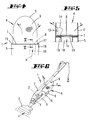
- a vacuum cleaner 1 is shown and described first with reference to FIG. 1, in particular a household vacuum cleaner with a not shown Electric motor 2, which drives a suction fan, the latter on the one hand Dirt sucks through a vacuum cleaner nozzle 3 (arrow a) and on the other hand the Blows dirt into a filter bag 4 arranged on the vacuum cleaner 1 (Arrow b).
- the filter bag 4 is directly on the vacuum cleaner 1 or on the electric motor 2 and the motor housing 5 containing the suction fan and forms part of the outer wall of the vacuum cleaner 1
- Filling designed filter bag 4 is multi-layer, as in Fig. 3rd shown four-ply, and air-permeable, so that the dirt-laden Air flow (arrow b) with complete filtration of all relevant Pollutants / contaminants through the filter bag wall 6 freely into the outside Environment can escape (arrow c).
- the filter bag 4 has one Holding plate 7, which in the illustrated embodiment is a plastic plate is. This is provided with a filling opening 8. On the bottom the holding plate 7 is the bag, the layers of which are at least partially made of plastic fibers exist, attached, for example. Welded to the holding plate 7.
- the filter bag 4 or its bag wall 6 is multi-layer, preferably four layers, one layer being self-supporting. In the exemplary embodiment shown, this is the flow direction c outermost layer 9 (see FIG. 3).
- This support layer 9 is preferably made of one Spun bond made. So is a relatively high mechanical strength Support the entire filter bag 4 given in a predetermined shape, so that no further measures to accommodate and protect against external Influences, such as by arranging one that receives the filter bag Chamber or the like are necessary.
- the innermost layer 12 a fleece with very high air permeability and a relatively low particulate matter separation rate. On the one hand, this serves to retain coarse dirt and on the other hand to prevent the build-up of a filter cake on the downstream filter layer 11.
- This layer 11 is one, preferably at least fleece layer partly made of plastic fibers with a high Dust storage capacity, which layer 11 in the flow direction c another Layer 10 is connected downstream. This preferably consists of a fine fiber fleece, like an electrostatically charged melt-blown fleece.
- the one already mentioned Outermost layer 9 is designed as a pure support medium and consists of a Plastic random fiber arrangement.
- the individual layers 9 to 12 are preferred arrested among themselves, e.g. laminated.
- an activated carbon granulate inside the filter bag 13 provided, which may be in bulk. How shown, this activated carbon granulate can also be in its own, air-permeable Envelope 14 may be present within the filter bag 4.
- the filter bag 4 is like already described, arranged directly on the motor housing 5, for example.
- the determination can be made such that the holding plate 7 with a narrow side area under a holding edge 15 arranged on the motor housing 5 occurs and the opposite narrow edge of the holding plate 7 for bracing the same against the motor housing 5 by one, with a handle 16 provided clamping element 17 is overlaid.
- the arrangement is chosen so that the filling opening 8 of the holding plate 7 is assigned to a flow channel 18 on the engine housing, the Interface is sealed by an annular seal 19.
- the filling opening 8 is on the inside of the bag from an automatically into a closed position when the vacuum cleaner is switched off 20 covered.
- the bag wall 6 of the filter bag 4 forms according to the above Embodiments part of the outer wall of the vacuum cleaner 1, wherein the support layer, preferably the outermost layer 9 of the filter bag 4, in shape holds. As a result, a significant weight reduction is more compact Design and slim design achieved. It is also exposed by the Filter bag 4 also a simplified level control by the user reached.
- the filter bag 4 is self-supporting and thus no receiving chamber or the like is needed, is also a variability in the filter bag size achieved in the simplest way.
- the bag volume can vary depending on the requirements. 6 is the Vacuum cleaner 1 with a volume compared to the configuration in Fig. 1 provided enlarged filter bag 4. Accordingly, depending on the application of the vacuum cleaner is adapted to a usual change interval volume Filter bag 4 can be arranged.
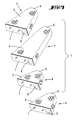
- the 7 shows a set of filter bags 4 of different sizes, which are provided with the same dimensioned holding plates 7.
- the bags of the filter bags 4 have at least essentially the same structure and have one Layer structure according to FIG. 3.
- the filter bags 4 are also corresponding of the set S is self-supporting.
- the filter bags 4 of the set S can also be different Bag size also through alternative layer structure and / or through different Differentiate amounts and / or types of absorbent material so that correspondingly large and / or corresponding for the most diverse vacuuming work Filter bags having filter properties are present.
- the main characteristics of this set S are the self-supporting layers of the filter bags 4 to form part of the outer wall of the vacuum cleaner 1, wherein preferably the outermost layer is designed as a support layer.
Abstract
Description
Die Erfindung betrifft zunächst einen Haushalt-Staubsauger mit einem Elektromotor und einem an dem Staubsauger angeordneten, mehrlagigen, luftdurchlässigen und nach Füllung zum Wegwerfen ausgelegten Filterbeutel zur Aufnahme von aufgesaugtem Schmutz, wobei der Elektromotor ein Sauggebläse antreibt, das einerseits den Schmutz durch eine Staubsaugerdüse ansaugt und andererseits den Schmutz in den Filterbeutel einbläst.The invention first relates to a household vacuum cleaner with an electric motor and a multi-layer, air-permeable arranged on the vacuum cleaner and after filling, filter bags designed for disposal Absorbing dirt, whereby the electric motor is a suction fan drives, which on the one hand sucks the dirt through a vacuum cleaner nozzle and on the other hand blows the dirt into the filter bag.
Haushalt-Staubsauger der in Rede stehenden Art sind bekannt. Diese weisen zur Festlegung und Aufnahme des Filterbeutels eine starre oder auch textile Filterbeutelkammer auf. Um den Hygiene- und Allergikeransprüchen gerecht zu werden, ist es weiter bekannt, in dem Luftströmungsweg des Staubsaugers zusätzlich zum Filterbeutel weitere Filterelemente an verschiedenen Stellen im Gerät anzuordnen.Household vacuum cleaners of the type in question are known. These point to fix and hold the filter bag a rigid or textile Filter bag chamber. To meet hygiene and allergy claims to become known, it is further known in the air flow path of the vacuum cleaner In addition to the filter bag, additional filter elements at various points in the Arrange device.
Im Hinblick auf den zuvor beschriebenen Stand der Technik wird eine technische Problematik der Erfindung darin gesehen, einen Haushalt-Staubsauger der in Rede stehenden Art insbesondere hinsichtlich einer verbesserten Handhabung in vorteilhafter Weise weiterzubilden.In view of the prior art described above, a technical Problems of the invention seen in a household vacuum cleaner Type in question in particular with regard to improved handling to train in an advantageous manner.
Diese Problematik ist zunächst durch den Gegenstand des Anspruches 1 gelöst,
wobei darauf abgestellt ist, dass der Filterbeutel einen Teil der Außenwandung
des Staubsaugers bildet, wobei mindestens eine Lage des Filterbeutels selbsttragend
ausgebildet ist. Zufolge dieser erfindungsgemäßen Ausgestaltung ist
ein Staubsauger geschaffen, welcher sich gegenüber einem vergleichbaren
Staubsauger mit, den Filterbeutel aufnehmender Filterkammer durch eine
deutliche Gewichtsreduktion bei kompakter Bauform und schlankem Design
auszeichnet. Durch die selbsttragende Ausbildung mindestens einer Lage des
Filterbeutels kann auf eine diesen aufnehmende, gegebenenfalls textile
Filterkammer verzichtet werden. Darüber hinaus ergeben sich Vorteile hinsichtlich
des Wechselns des direkt an dem Motorgehäuse des Staubsaugers angeschlossenen
Filterbeutels. Durch die mehrlagige Ausbildung des Filterbeutels
ist darüber hinaus ein System geschaffen, welches mit nur einem Filter,
nämlich dem endständig hinsichtlich des Luftströmungsweges angeordneten
Filterbeutels zur kompletten Filtration aller relevanten Stoffe, wie Grobstaub,
Feinstaub, Allergene, Pilzsporen, Bakterien, Motoremissionen, Geruch usw.
auskommt. Hierzu sind unterschiedliche, in Strömrichtung der Filterwandung
aufeinander folgende Filterlagen vorgesehen. Dementsprechend braucht der
Benutzer nicht auf verschiedene Wechselintervalle mehrerer in dem Staubsauger
angeordneter Filter zu achten. Vielmehr wird bei einem üblichen Filterbeutelwechsel
das gesamte Filtersystem des Staubsaugers erneuert. So kann weiter
vorgesehen sein, dass in dem Filterbeutel, bspw. in Form einer Beutellage Aktivkohle
angeordnet ist. Bevorzugt wird diesbezüglich eine lose Anordnung
von Aktivkohlegranulat in dem Filterbeutel. Diesbezüglich wird auf die
DE 100 30 958 A1 verwiesen. Der Inhalt dieser Patentanmeldung wird hiermit
vollinhaltlich in die Offenbarung vorliegender Erfindung mit einbezogen, auch
zu dem Zwecke, Merkmale dieser Patentanmeldung in Ansprüche vorliegender
Erfindung mit einzubeziehen. So kann das Adsorbens unmittelbar in dem
Staubsammelraum des Filterbeutels in loser Form oder auch in einer eigenen,
luftdurchlässigen Umhüllung angeordnet sein. Diesbezüglich werden Aktivkohlefasern
mit einem Faserdurchmesser von 0,01 bis 0,1 mm und einer Faserlänge
von 10 bis 100 mm oder Aktivkohlepulver mit einer Korngrößenfraktion
zwischen 0,15 und 0,25 bevorzugt. Des Weiteren ergibt sich durch die erfindungsgemäße,
freiliegende Anordnung des Filterbeutels an dem Staubsauger
der Vorteil einer für den Benutzer erleichterten Füllstandskontrolle. So kann
der Füllstand unmittelbar an dem freiliegenden, endständig angeordneten Filterbeutel
abgelesen werden. In einer Weiterbildung des Erfindungsgegenstandes
ist bei einem Staubsauger der in Rede stehenden Art, wobei der Filterbeutel
eine Halteplatte aufweist, vorgesehen, dass die Halteplatte eine Kunststoffplatte
ist. Diese weist die nötige Stabilität zum direkten Anschluss des Filterbeutels
an dem Staubsauger bzw. an dessen Motorgehäuse auf. So kann die Festlegung
des Filterbeutels in einfachster Weise durch eine Klemmhalterung auf dem Motorgehäuse
erreicht sein, welche Klemmhalterung auf die Halteplatte einwirkt.
Auch wird vorgeschlagen, dass alle Lagen des Filterbeutels zumindest teilweise
aus Kunststofffasern bestehen. Möglich ist auch eine Kombination mit einer
Papier-Zwischenlage. Demzufolge kann der Beutel an der bevorzugt aus
Kunststoff hergestellten Halteplatte angeschweißt sein. Des Weiteren ergibt
sich hieraus der vorteilhafte Effekt, dass durch partielles Anschmelzen eine
Verhaftung der Lagen untereinander erreicht wird, so dass die selbsttragend
ausgebildete Lage des Filterbeutels die weiteren Lagen mitträgt und somit den
Filterbeutel in einer vorbestimmten Form hält. Die Kunststofffasern können
bspw. Melt-Blown-, Spitfibre- oder auch Bicomponent-Fasern sein, die thermisch,
chemisch oder mechanisch miteinander vernetzt sind. Die einzelnen
Lagen können darüber hinaus miteinander laminiert sein. Dadurch bedingt,
dass durch die erfindungsgemäße Ausgestaltung des Filterbeutels und dessen
direkte, freiliegende Anordnung an dem Staubsauger eine diesen aufnehmende
Filterkammer entfällt, resultiert ein weiterer vorteilhafter Effekt, indem der
Staubsauger durch unterschiedlich große Filterbeutel in seiner Außenkontur
unterschiedlich gestaltbar ist. So können in einfachster Weise den Gegebenheiten
angepasst verschiedene Filterbeutelgrößen angeordnet werden. Auch die
Anordnung verschiedener Filterbeutel mit unterschiedlichen Filterqualitäten ist
denkbar. Zufolge dieser Ausgestaltung ist eine an ein übliches Wechselintervall
angepasste Filterbeutelgröße wählbar, so dass nicht, wie bei der üblichen Anordnung
stets gleich großer Filterbeutel üblich, der Wechselintervall, bspw. bei
Verwendung des Staubsaugers in kleineren Wohnungen, zwischen zwei und
drei Monaten und bei größeren Wohnungen oder im gewerblichen Bereich bei
ein bis zwei Tagen liegt, was einerseits bei zu langen Wechselintervallen unter
hygienischen Gesichtspunkten kritisch zu bewerten ist und andererseits bei
sehr kurzen Wechselintervallen hinsichtlich der Handhabung nicht erwünscht
ist. So würde bspw. beim Einsatz des Staubsaugers in kleineren Wohnungen
ein entsprechend kleinerer Filterbeutel angeordnet werden. Hingegen könnte
bei einem Einsatz in bspw. gewerblichen Räumen ein Filterbeutel mit einem
letzterem gegenüber vielfachen Volumen Anwendung finden. Als besonders
vorteilhaft erweist sich eine Ausgestaltung, bei welcher nur die äußerste Lage
des Filterbeutels als Stützschicht ausgebildet ist. Diese äußerste Lage übernimmt
hierbei zugleich die Funktion einer Schutzlage gegen äußere mechanische
Einflüsse. Hinsichtlich des Lagenaufbaus wird auf die DE 196 06 718 A1
verwiesen. Auch der Inhalt dieser Patentanmeldung wird hiermit vollinhaltlich
in die Offenbarung vorliegender Erfindung mit einbezogen, auch zu dem
Zwecke, Merkmale dieser Patentanmeldung in Ansprüche vorliegender Erfindung
mit einzubeziehen. So kann eine erste, in Durchströmrichtung betrachtete
innerste Lage aus einem Vlies mit sehr hoher Luftdurchlässigkeit bestehen, zur
Rückhaltung von Grobschmutz und zum Verhindern des Aufbauens eines Filterkuchens
auf der nachgeschalteten Filterlage. Diese nachgeschaltete Lage
weist eine hohe Staubspeicherfähigkeit auf. Eine in Durchströmrichtung nachfolgende
dritte Lage kann bspw. ein Feinfaservlies, wie ein elektrostatisch aufgeladenes
Melt-Blown-Vlies sein. Die, die mechanische Festigkeit und somit
die Stützschicht ausbildende äußerste Lage ist weiter bevorzugt im
Spun-Bond-Verfahren hergestellt, zur Bildung eines Spinnvlieses. Des Weiteren
ist auch denkbar, diese Stützlage des Filterbeutels elastisch auszuformen, so
dass die Filterbeutel-Außenkontur anpassbar ist an das aufgenommene
Staub-/Schmutzvolumen. Da erfindungsgemäß der Filterbeutel endständig,
demnach das letzte Glied in einer möglichen Filterkette ist, ist weiter vorgesehen,
dass der Filterbeutel einer HEPA-Klasse genügt, so mindestens H10, besser
H11 oder H12, weiter bevorzugt H13. So ist vorgesehen, dass der Filterbeutel
einen Abscheidegrad von mehr als 85%, bevorzugt mehr als 95%, weiter bevorzugt
von mehr als 99,5%, darüber hinaus weiter bevorzugt von mehr als 99,95%
bezogen auf den MPPS (Most Penetrating Particle Size) nach der Norm EN 1822
besitzt. This problem is first solved by the subject matter of
Die Erfindung betrifft des Weiteren ein Set von Filterbeuteln für einen bestimmten Haushalt-Staubsaugertyp. Um ein derartiges Set anzugeben, welches eine Anpassung auf verschiedene Gegebenheiten unter Berücksichtigung des üblichen Wechselintervalls bietet, werden Filterbeutel unterschiedlicher Größe vorgeschlagen. So kann bspw. ein Set zwei, drei, vier, fünf oder mehr unterschiedlich große Filterbeutel für denselben Haushalt-Staubsaugertyp beinhalten. Entsprechend kann nach Bedarf ein an ein übliches Wechselintervall angepasster Filterbeutel gewählt werden. Darüber hinaus besteht die Möglichkeit, die Filterbeutelgröße in Abhängigkeit von der bevorstehenden Reinigungsaufgabe zu wählen. Ist beispielsweise das Aufsaugen von leicht feuchten Substanzen vorgesehen, kann hierfür ein kleinerer Filterbeutel des Sets benutzt werden, um diesen nach Beendigung des Saugarbeit direkt zu entsorgen. Zum täglichen Saugen bspw. gewerblicher Räume hingegen wird ein auf ein übliches Wechselintervall angepasster größerer Filterbeutel des Sets genutzt. Als besonders vorteilhaft erweist sich hierbei ein Set von Filterbeuteln gemäß den Ansprüchen 1 bis 6. So wird bei einem erfindungsgemäßen Set, wobei ein Filterbeutel mehrlagig ausgebildet ist, vorgeschlagen, dass ein Filterbeutel des Filterbeutelsets zur Bildung eines Teils der Außenwandung des Staubsaugers mindestens eine selbsttragende Lage aufweist. Zufolge dieser erfindungsgemäßen Ausgestaltung ist ein Filterbeutelset geschaffen, welches gegenüber vergleichbaren Staubsauger/Filterbeutelkombinationen, bei welchen der Filterbeutel in einer Filterkammer aufgenommen ist, zur deutlichen Gewichtsreduktion bei kompakter Bauform und schlanken Design des Staubsaugers beiträgt. Durch die selbsttragende Ausbildung mindestens einer Lage des Filterbeutels kann auf eine diesen aufnehmende, gegebenenfalls textile Filterkammer verzichtet werden. Darüber hinaus ergeben sich Vorteile hinsichtlich des Wechselns des direkt an dem Motorgehäuse des Staubsaugers angeschlossenen Filterbeutels, was weiter den Wechsel von Filterbeuteln innerhalb des erfindungsgemäßen Sets vereinfacht. In einer Weiterbildung des Erfindungsgegenstandes ist bei einem Set der in Rede stehenden Art, wobei ein Filterbeutel eine Halteplatte aufweist, vorgesehen, dass die Halteplatte eine Kunststoffplatte ist. Diese weist die nötige Stabilität zum direkten Anschluss des Filterbeutels an dem Staubsauger bzw. an dessen Motorgehäuse auf. So kann die Festlegung des Filterbeutels in einfachster Weise durch eine Klemmhalterung auf dem Motorgehäuse erreicht sein. Auch wird vorgeschlagen, dass alle Lagen eines Filterbeutels zumindest teilweise aus Kunststofffasern bestehen. Möglich ist auch eine Kombination mit einer Papier-Zwischenlage. Demzufolge kann der Beutel an der bevorzugt aus Kunststoff hergestellten Halteplatte angeschweißt sein. Des Weiteren ergibt sich hieraus der vorteilhafte Effekt, dass durch partielles Anschmelzen eine Verhaftung der Lagen untereinander erreicht wird, so dass die selbsttragend ausgebildete Lage eines Filterbeutels die weiteren Lagen mitträgt und somit den Filterbeutel in einer vorbestimmten Form hält. Als besonders vorteilhaft erweist sich eine Ausgestaltung, bei welcher nur die äußerste Lage eines Filterbeutels als Stützschicht ausgebildet ist. Diese äußerste Lage übernimmt hierbei zugleich die Funktion einer Schutzlage gegen äußere mechanische Einflüsse. Schließlich wird vorgeschlagen, dass ein Filterbeutel einen Abscheidegrad von mehr als 85%, bevorzugt mehr als 95%, weiter bevorzugt von mehr als 99,5%, darüber hinaus weiter bevorzugt von mehr als 99,95% nach der Norm EN 1822 besitzt, womit bevorzugt jeder Filterbeutel des Sets einer HEPA-Klasse genügt, mit mindestens H10, besser H11 oder H12, bevorzugt sogar H13.The invention further relates to a set of filter bags for a specific one Household vacuum cleaner type. To specify such a set, which one Adaptation to different circumstances taking into account the usual Offers changing intervals, filter bags of different sizes are proposed. For example, a set can be two, three, four, five or more different contain large filter bags for the same household vacuum cleaner type. Corresponding can be adapted to a normal change interval as required Filter bags can be selected. There is also the option of filter bag size depending on the upcoming cleaning task choose. If, for example, the suction of slightly moist substances is provided, a smaller filter bag from the set can be used to to dispose of it immediately after the end of the suction work. For everyday Vacuuming, for example, commercial rooms, on the other hand, is changed to a normal change interval adapted larger filter bag of the set used. As special A set of filter bags according to the claims proves advantageous here 1 to 6. This is the case with a set according to the invention, with a filter bag is designed in multiple layers, it is proposed that a filter bag of the filter bag set to form part of the outer wall of the vacuum cleaner at least has a self-supporting position. As a result of this configuration according to the invention is a filter bag set created, which compared to comparable Vacuum cleaner / filter bag combinations, in which the filter bag in one Filter chamber is included, for significant weight reduction in a more compact Construction and slim design of the vacuum cleaner contributes. Through the self-supporting formation of at least one layer of the filter bag can a filter chamber accommodating this, if necessary textile, can be dispensed with. In addition, there are advantages with regard to changing the direct filter bag connected to the motor housing of the vacuum cleaner, what further the change of filter bags within the set according to the invention simplified. In a further development of the subject matter of the invention Set of the type in question, wherein a filter bag has a holding plate, provided that the holding plate is a plastic plate. This shows the necessary Stability for direct connection of the filter bag to the vacuum cleaner or to whose motor housing on. So the definition of the filter bag can be done in the simplest Be achieved by a clamp on the motor housing. It is also proposed that all layers of a filter bag are at least partially consist of plastic fibers. A combination with is also possible a paper liner. As a result, the bag can preferably be made from Plastic-made mounting plate to be welded. Furthermore follows from this the advantageous effect that an attachment by partial melting the layers are reached with each other, so that the self-supporting trained Layer of a filter bag carries the other layers and thus the filter bag holds in a predetermined form. It has proven to be particularly advantageous an embodiment in which only the outermost layer of a filter bag as Support layer is formed. This outermost position takes over at the same time the function of a protective layer against external mechanical influences. Finally it is proposed that a filter bag have a degree of separation of more than 85%, preferably more than 95%, more preferably more than 99.5%, above furthermore preferably has more than 99.95% according to the standard EN 1822, which means that each filter bag in the set is sufficient for one HEPA class at least H10, better H11 or H12, preferably even H13.
Nachstehend ist die Erfindung anhand der beigefügten Zeichnungen, welche lediglich ein Ausführungsbeispiel darstellen, näher erläutert. Es zeigt:
- Fig. 1
- einen erfindungsgemäßen Haushalt-Staubsauger in perspektivischer Darstellung;
- Fig. 2
- in perspektivischer Einzeldarstellung einen Filterbeutel des Staubsaugers;
- Fig. 3
- den stark vergrößerten Schnitt gemäß der Linie III-III in Fig. 2;
- Fig. 4
- den an dem Motorgehäuse des Staubsaugers angeordneten Filterbeutel in Ansicht;
- Fig. 5
- den Schnitt gemäß der Linie V-V in Fig. 4;
- Fig. 6
- eine der Fig. 1 entsprechende perspektivische Darstellung des Staubsaugers, jedoch bei Anordnung eines gegenüber Fig. 1 größeren Filterbeutels;
- Fig. 7
- in perspektivischer Darstellung ein Set von Filterbeuteln unterschiedlicher Größe für einen Staubsauger gemäß Fig. 1.
- Fig. 1
- a household vacuum cleaner according to the invention in a perspective view;
- Fig. 2
- in perspective individual representation of a filter bag of the vacuum cleaner;
- Fig. 3
- the greatly enlarged section along the line III-III in Fig. 2;
- Fig. 4
- the filter bag arranged on the motor housing of the vacuum cleaner in view;
- Fig. 5
- the section along the line VV in Fig. 4;
- Fig. 6
- 1 a perspective view of the vacuum cleaner corresponding to FIG. 1, but with the arrangement of a filter bag larger than that of FIG. 1;
- Fig. 7
- a perspective view of a set of filter bags of different sizes for a vacuum cleaner according to FIG. 1.
Dargestellt und beschrieben ist zunächst mit Bezug zu Fig. 1 ein Staubsauger 1,
insbesondere ein Haushalt-Staubsauger mit einem nicht näher dargestellten
Elektromotor 2, der ein Sauggebläse antreibt, welch letzteres einerseits den
Schmutz durch eine Staubsaugerdüse 3 ansaugt (Pfeil a) und andererseits den
Schmutz in einen an dem Staubsauger 1 angeordneten Filterbeutel 4 einbläst
(Pfeil b).A
Der Filterbeutel 4 ist unmittelbar an dem Staubsauger 1 bzw. an dem, den Elektromotor
2 und das Sauggebläse beinhaltenden Motorgehäuse 5 angeordnet
und bildet hierbei einen Teil der Außenwandung des Staubsaugers 1. Der nach
Füllung zum Wegwerfen ausgelegte Filterbeutel 4 ist mehrlagig, wie in Fig. 3
dargestellt vierlagig, und luftdurchlässig ausgebildet, so dass der schmutzbeladene
Luftstrom (Pfeil b) unter kompletter Filtration aller relevanten
Schad-/Schmutzstoffe durch die Filterbeutelwandung 6 frei nach außen in die
Umgebung austreten kann (Pfeil c). The
Wie in der Einzeldarstellung in Fig. 2 zu erkennen, weist der Filterbeutel 4 eine
Halteplatte 7 auf, welche in dem dargestellten Ausführungsbeispiel eine Kunststoffplatte
ist. Diese ist mit einer Einfüllöffnung 8 versehen. An der Unterseite
der Halteplatte 7 ist der Beutel, dessen Lagen zumindest teilweise aus Kunststofffasern
bestehen, befestigt, so bspw. mit der Halteplatte 7 verschweißt.As can be seen in the individual illustration in FIG. 2, the
Wie erwähnt, ist der Filterbeutel 4 bzw. dessen Beutelwandung 6 mehrlagig,
bevorzugt vierlagig ausgebildet, wobei eine Lage selbsttragend ausgeformt ist.
In dem dargestellten Ausführungsbeispiel ist dies die in Durchströmrichtung c
äußerste Lage 9 (vergl. Fig. 3). Diese Stützlage 9 ist vorzugsweise aus einem
Spun-Bond hergestellt. So ist eine relativ hohe mechanische Festigkeit zum
Stützen des gesamten Filterbeutels 4 in einer vorbestimmten Form gegeben, so
dass keine weiteren Maßnahmen zur Aufnahme und zum Schutz vor äußeren
Einflüssen, wie bspw. durch Anordnung einer, den Filterbeutel aufnehmenden
Kammer oder dergleichen notwendig sind.As mentioned, the
Die in Durchströmrichtung c innenseitig der Stützlage 9 angeordneten weiteren
Lagen dienen der Filtration, wobei den weiteren Lagen 10 bis 12 unterschiedliche
Aufgaben zukommen. So handelt es sich bspw. bei der innersten Lage 12
um ein Vlies mit sehr hoher Luftdurchlässigkeit und relativ geringer Feinststaub-Abscheideleistung.
Diese dient zum einen der Rückhaltung von Grobschmutz
und zum anderen zur Verhinderung des Aufbaus eines Filterkuchens
auf der nachgeschalteten Filterlage 11. Diese Lage 11 ist eine, bevorzugt zumindest
teilweise aus Kunststofffasern bestehende Vlieslage mit einer hohen
Staubspeicherfähigkeit, welcher Lage 11 in Durchströmrichtung c eine weitere
Lage 10 nachgeschaltet ist. Diese besteht bevorzugt aus einem Feinfaservlies,
wie ein elektrostatisch aufgeladenes Melt-Blown-Vlies. Die bereits erwähnte
äußerste Lage 9 ist als reines Stützmedium ausgebildet und besteht aus einer
Kunststoff-Wirrfaser-Anordnung. Die einzelnen Lagen 9 bis 12 sind bevorzugt
untereinander verhaftet, bspw. laminiert.The others arranged in the flow direction c on the inside of the
Zur Geruchsadsorption ist des Weiteren im Filterbeutelinneren ein Aktivkohle-Granulat
13 vorgesehen, welches in loser Form vorhanden sein kann. Wie
dargestellt, kann dieses Aktivkohle-Granulat auch in einer eigenen, luftdurchlässigen
Umhüllung 14 innerhalb des Filterbeutels 4 vorhanden sein.For odor adsorption there is also an activated carbon granulate inside the filter bag
13 provided, which may be in bulk. How
shown, this activated carbon granulate can also be in its own, air-
Zufolge der zuvor beschriebenen Ausgestaltung des Filterbeutels 4 übernimmt
dieser die komplette Filtration aller relevanten Schadstoffe, so dass mit einem
Austausch des Filterbeutels 4 zur Entsorgung desselben zugleich sämtliche Filter
des Systems ausgetauscht werden.As a result of the previously described design of the
Wie insbesondere aus den Fig. 4 und 5 zu erkennen, wird der Filterbeutel 4, wie
bereits beschrieben, direkt an dem Motorgehäuse 5 angeordnet, wobei bspw.
die Festlegung derart erfolgen kann, dass die Halteplatte 7 mit einem Schmalseitenbereich
unter eine an dem Motorgehäuse 5 angeordnete Haltekante 15
tritt und die gegenüberliegende Schmalrandkante der Halteplatte 7 zur Verspannung
derselben gegen das Motorgehäuse 5 von einem, mit einer Handhabe
16 versehenen Spannelement 17 überfangen wird.As can be seen in particular from FIGS. 4 and 5, the
Die Anordnung ist hierbei so gewählt, dass die Einfüllöffnung 8 der Halteplatte
7 einem motorgehäuseseitigen Strömungskanal 18 zugeordnet ist, wobei die
Schnittstelle durch eine Ringdichtung 19 abgedichtet ist.The arrangement is chosen so that the filling
Die Einfüllöffnung 8 ist beutelinnenseitig von einer selbsttätig in eine Verschlussstellung
bei einem Ausschalten des Staubsaugers sich verlagernden Verschlussklappe
20 überdeckt. The filling
Die Beutelwandung 6 des Filterbeutels 4 bildet zufolge der vorbeschriebenen
Ausgestaltungen einen Teil der Außenwandung des Staubsaugers 1 aus, wobei
die Stützlage, bevorzugt die äußerste Lage 9 des Filterbeutels 4 diesen in Form
hält. Zufolge dessen ist eine deutliche Gewichtsreduktion bei kompakter
Bauform und schlankem Design erreicht. Darüber hinaus ist durch den freiliegenden
Filterbeutel 4 auch eine vereinfachte Füllstandskontrolle durch den Benutzer
erreicht.The
Dadurch bedingt, dass der Filterbeutel 4 selbsttragend ausgebildet ist und somit
keine diesen aufnehmende Kammer oder dergleichen benötigt wird, ist auch
eine Variabilität hinsichtlich der Filterbeutelgröße in einfachster Weise erreicht.
So kann das Beutelvolumen je nach Anforderung variieren. In Fig. 6 ist der
Staubsauger 1 mit einem gegenüber der Konfiguration in Fig. 1 volumenmäßig
vergrößerten Filterbeutel 4 versehen. Demzufolge ist je nach Anwendungsbereich
des Staubsaugers ein an ein übliches Wechselintervallvolumen angepasster
Filterbeutel 4 anordbar.This means that the
In Fig. 7 ist ein Set von Filterbeuteln 4 unterschiedlicher Größe dargestellt, welche
mit gleichdimensionierten Halteplatten 7 versehen sind. Die Beutel der Filterbeutel
4 sind zumindest im Wesentlichen gleich aufgebaut und weisen einen
Lagenaufbau gemäß Fig. 3 auf. Dementsprechend sind auch die Filterbeutel 4
des Sets S selbsttragend ausgeformt.7 shows a set of
Die Filterbeutel 4 des Sets S können sich zudem neben der unterschiedlichen
Beutelgröße auch durch alternativen Lagenaufbau und/oder durch verschiedene
Mengen und/oder Arten von Absorptionsmaterial unterscheiden, so dass
für die verschiedensten Staubsaugarbeiten entsprechend große und/oder entsprechende
Filtereigenschaften aufweisende Filterbeutel vorliegen. The
Wesentliche Merkmale dieses Sets S sind die selbsttragenden Lagen der Filterbeutel
4 zur Bildung eines Teils der Außenwandung des Staubsaugers 1, wobei
bevorzugt die äußerste Lage als Stützschicht ausgebildet ist.The main characteristics of this set S are the self-supporting layers of the
Alle offenbarten Merkmale sind (für sich) erfindungswesentlich. In die Offenbarung der Anmeldung wird hiermit auch der Offenbarungsinhalt der zugehörigen/beigefügten Prioritätsunterlagen (Abschrift der Voranmeldung) vollinhaltlich mit einbezogen, auch zu dem Zweck, Merkmale dieser Unterlagen in Ansprüche vorliegender Anmeldung mit aufzunehmen.All of the features disclosed are (in themselves) essential to the invention. In the revelation the disclosure also hereby includes the disclosure content of the associated / attached Priority documents (copy of the pre-registration) in full included, also for the purpose, characteristics of these documents in To include claims of the present application.
Claims (12)
Applications Claiming Priority (4)
| Application Number | Priority Date | Filing Date | Title |
|---|---|---|---|
| DE10213226 | 2002-03-25 | ||
| DE10213226 | 2002-03-25 | ||
| DE10228034A DE10228034A1 (en) | 2002-03-25 | 2002-06-24 | Household vacuum cleaner with a filter bag and set of filter bags |
| DE10228034 | 2002-06-24 |
Publications (2)
| Publication Number | Publication Date |
|---|---|
| EP1350457A2 true EP1350457A2 (en) | 2003-10-08 |
| EP1350457A3 EP1350457A3 (en) | 2004-01-02 |
Family
ID=28042860
Family Applications (1)
| Application Number | Title | Priority Date | Filing Date |
|---|---|---|---|
| EP03006333A Pending EP1350457A3 (en) | 2002-03-25 | 2003-03-20 | Domestic vacuum cleaner comprising a dust bag, and set of dust bags |
Country Status (1)
| Country | Link |
|---|---|
| EP (1) | EP1350457A3 (en) |
Cited By (3)
| Publication number | Priority date | Publication date | Assignee | Title |
|---|---|---|---|---|
| DE102004013263A1 (en) * | 2004-03-18 | 2005-09-29 | Vorwerk & Co. Interholding Gmbh | Electric vacuum cleaner |
| EP1695649A1 (en) * | 2005-02-28 | 2006-08-30 | Matsushita Electric Industrial Co., Ltd. | Vacuum cleaner and dust bag for vacuum cleaner |
| CN100387176C (en) * | 2005-02-28 | 2008-05-14 | 松下电器产业株式会社 | Vacuum cleaner and dust bag for vacuum cleaner |
Citations (11)
| Publication number | Priority date | Publication date | Assignee | Title |
|---|---|---|---|---|
| DE1428431A1 (en) * | 1962-02-05 | 1969-01-23 | Licentia Gmbh | Vacuum cleaner outer bag |
| DE3234837A1 (en) * | 1982-09-21 | 1984-03-22 | Progress-Elektrogeräte Mauz & Pfeiffer GmbH & Co, 7000 Stuttgart | Fastener for a dust filter and dust collection part of a cleaning apparatus |
| EP0134395A1 (en) * | 1983-07-19 | 1985-03-20 | Vorwerk & Co. Interholding GmbH | Filter receptacle for a hand suction cleaner |
| JPH06284995A (en) * | 1993-03-30 | 1994-10-11 | Mitsubishi Electric Home Appliance Co Ltd | Vacuum cleaner |
| JPH06284996A (en) * | 1993-03-31 | 1994-10-11 | Nec Home Electron Ltd | Vacuum cleaner and set of dust bags |
| US5522908A (en) * | 1994-05-27 | 1996-06-04 | Hmi Industries, Inc. | Filter bag for a vacuum cleaner |
| DE19606718A1 (en) * | 1996-02-23 | 1997-08-28 | Vorwerk Co Interholding | Multi-layer filter bag |
| DE10030958A1 (en) * | 1999-07-29 | 2001-02-01 | Vorwerk Co Interholding | Hand vacuum cleaner which retains smell, comprises dust collection chamber, and adsorber, e.g. active charcoal, which is placed in Collection chamber |
| DE19948563A1 (en) * | 1999-10-08 | 2001-04-12 | Roland Kuhblank | Dust filter bag for vacuum cleaners has dust collection filter bag with connection openings, air tight cover elements, adapter plate with deformable connecting element for insertion in opening |
| US6277163B1 (en) * | 1999-04-06 | 2001-08-21 | Oreck Holdings Llc | Vacuum cleaner outer bag |
| DE10137064A1 (en) * | 2001-07-28 | 2003-02-13 | Vorwerk Co Interholding | Electric power vacuum cleaner has suction fan to feed air to variable volume collection chamber |
-
2003
- 2003-03-20 EP EP03006333A patent/EP1350457A3/en active Pending
Patent Citations (11)
| Publication number | Priority date | Publication date | Assignee | Title |
|---|---|---|---|---|
| DE1428431A1 (en) * | 1962-02-05 | 1969-01-23 | Licentia Gmbh | Vacuum cleaner outer bag |
| DE3234837A1 (en) * | 1982-09-21 | 1984-03-22 | Progress-Elektrogeräte Mauz & Pfeiffer GmbH & Co, 7000 Stuttgart | Fastener for a dust filter and dust collection part of a cleaning apparatus |
| EP0134395A1 (en) * | 1983-07-19 | 1985-03-20 | Vorwerk & Co. Interholding GmbH | Filter receptacle for a hand suction cleaner |
| JPH06284995A (en) * | 1993-03-30 | 1994-10-11 | Mitsubishi Electric Home Appliance Co Ltd | Vacuum cleaner |
| JPH06284996A (en) * | 1993-03-31 | 1994-10-11 | Nec Home Electron Ltd | Vacuum cleaner and set of dust bags |
| US5522908A (en) * | 1994-05-27 | 1996-06-04 | Hmi Industries, Inc. | Filter bag for a vacuum cleaner |
| DE19606718A1 (en) * | 1996-02-23 | 1997-08-28 | Vorwerk Co Interholding | Multi-layer filter bag |
| US6277163B1 (en) * | 1999-04-06 | 2001-08-21 | Oreck Holdings Llc | Vacuum cleaner outer bag |
| DE10030958A1 (en) * | 1999-07-29 | 2001-02-01 | Vorwerk Co Interholding | Hand vacuum cleaner which retains smell, comprises dust collection chamber, and adsorber, e.g. active charcoal, which is placed in Collection chamber |
| DE19948563A1 (en) * | 1999-10-08 | 2001-04-12 | Roland Kuhblank | Dust filter bag for vacuum cleaners has dust collection filter bag with connection openings, air tight cover elements, adapter plate with deformable connecting element for insertion in opening |
| DE10137064A1 (en) * | 2001-07-28 | 2003-02-13 | Vorwerk Co Interholding | Electric power vacuum cleaner has suction fan to feed air to variable volume collection chamber |
Non-Patent Citations (2)
| Title |
|---|
| PATENT ABSTRACTS OF JAPAN vol. 1995, no. 01, 28. Februar 1995 (1995-02-28) -& JP 06 284995 A (MITSUBISHI ELECTRIC HOME APPLIANCE CO LTD ET AL), 11. Oktober 1994 (1994-10-11) * |
| PATENT ABSTRACTS OF JAPAN vol. 1995, no. 01, 28. Februar 1995 (1995-02-28) -& JP 06 284996 A (NEC HOME ELECTRON LTD), 11. Oktober 1994 (1994-10-11) * |
Cited By (3)
| Publication number | Priority date | Publication date | Assignee | Title |
|---|---|---|---|---|
| DE102004013263A1 (en) * | 2004-03-18 | 2005-09-29 | Vorwerk & Co. Interholding Gmbh | Electric vacuum cleaner |
| EP1695649A1 (en) * | 2005-02-28 | 2006-08-30 | Matsushita Electric Industrial Co., Ltd. | Vacuum cleaner and dust bag for vacuum cleaner |
| CN100387176C (en) * | 2005-02-28 | 2008-05-14 | 松下电器产业株式会社 | Vacuum cleaner and dust bag for vacuum cleaner |
Also Published As
| Publication number | Publication date |
|---|---|
| EP1350457A3 (en) | 2004-01-02 |
Similar Documents
| Publication | Publication Date | Title |
|---|---|---|
| EP1795248B1 (en) | Vacuum cleaner bag | |
| DE10120223B4 (en) | Multi-layer air filter and its use | |
| EP2215951B1 (en) | Filter bag | |
| EP1725153A1 (en) | Adsorbing agent, dust collection chamber, and method for the adsorption of smells | |
| EP1694188B1 (en) | Vacuum cleaner bag and method for extending the service life thereof | |
| DE202005007503U1 (en) | filter bag | |
| WO2001008543A1 (en) | Method for vacuum-cleaning using a hand vacuum cleaner and dust filter bags or dust collection compartment, especially for use in a method of this type | |
| EP1495709B1 (en) | Dust filter bag for a vacuum cleaner | |
| DE29924781U1 (en) | Vacuum cleaner bag and improved vacuum cleaner bag | |
| DE102008011723A1 (en) | Method for operation of vacuum cleaner, particularly household vacuum cleaner, involves forming filter layer in dust receiver at beginning or before dust eyes of wall | |
| EP1350457A2 (en) | Domestic vacuum cleaner comprising a dust bag, and set of dust bags | |
| EP1493372B1 (en) | Dust filter bag comprising adsorbent material for a vacuum cleaner | |
| DE102007006502A1 (en) | Single- or multi-layer designed dust filter bag for e.g. hand-operated stick device, has loosely recovered substance free from separately brought adsorber particles and having high roughness and /or texturizing or bagginess regarding fibers | |
| DE10228034A1 (en) | Household vacuum cleaner with a filter bag and set of filter bags | |
| WO2003073902A1 (en) | Filter bag with scent element | |
| DE102008018189B4 (en) | Electrically operated vacuum cleaner | |
| DE19615209C1 (en) | Vacuum cleaner bag | |
| DE4322222A1 (en) | Filter for vacuum cleaners | |
| WO1996019935A1 (en) | Filter and filter bag for vacuum cleaners | |
| DE19820153C1 (en) | Filter unit for a dirt sucking apparatus | |
| EP2066214B1 (en) | Dust filter bag in multi-layer design | |
| DE102009009324A1 (en) | Particulate matter-filter cassette for vacuum cleaner i.e. bag-less vacuum cleaner, has container arranged at distance from inner contour of filter cassette, and dust binding medium accommodated in container in swirling manner | |
| DE102007029040B4 (en) | Dust bag and nonwoven material for producing a dust bag | |
| DE19709061A1 (en) | Air filter, in particular for dust-laden air from a vacuum cleaner | |
| DE20023762U1 (en) | Hand vacuum cleaner which retains smell, comprises dust collection chamber, and adsorber, e.g. active charcoal, which is placed in Collection chamber |
Legal Events
| Date | Code | Title | Description |
|---|---|---|---|
| PUAI | Public reference made under article 153(3) epc to a published international application that has entered the european phase |
Free format text: ORIGINAL CODE: 0009012 |
|
| AK | Designated contracting states |
Kind code of ref document: A2 Designated state(s): AT BE BG CH CY CZ DE DK EE ES FI FR GB GR HU IE IT LI LU MC NL PT RO SE SI SK TR |
|
| AX | Request for extension of the european patent |
Extension state: AL LT LV MK |
|
| PUAL | Search report despatched |
Free format text: ORIGINAL CODE: 0009013 |
|
| AK | Designated contracting states |
Kind code of ref document: A3 Designated state(s): AT BE BG CH CY CZ DE DK EE ES FI FR GB GR HU IE IT LI LU MC NL PT RO SE SI SK TR |
|
| AX | Request for extension of the european patent |
Extension state: AL LT LV MK |
|
| RIN1 | Information on inventor provided before grant (corrected) |
Inventor name: SAUER, RALF Inventor name: RODEMANN, THOMAS |
|
| STAA | Information on the status of an ep patent application or granted ep patent |
Free format text: STATUS: REQUEST FOR EXAMINATION WAS MADE |
|
| 17P | Request for examination filed |
Effective date: 20040630 |
|
| AKX | Designation fees paid |
Designated state(s): AT DE ES FR IT |