EP1349091A2 - LSI mask manufacturing system, LSI mask manufacturing method and LSI mask manufacturing program - Google Patents
LSI mask manufacturing system, LSI mask manufacturing method and LSI mask manufacturing program Download PDFInfo
- Publication number
- EP1349091A2 EP1349091A2 EP03006732A EP03006732A EP1349091A2 EP 1349091 A2 EP1349091 A2 EP 1349091A2 EP 03006732 A EP03006732 A EP 03006732A EP 03006732 A EP03006732 A EP 03006732A EP 1349091 A2 EP1349091 A2 EP 1349091A2
- Authority
- EP
- European Patent Office
- Prior art keywords
- lithography
- unit
- mask manufacturing
- user terminal
- data
- Prior art date
- Legal status (The legal status is an assumption and is not a legal conclusion. Google has not performed a legal analysis and makes no representation as to the accuracy of the status listed.)
- Granted
Links
Images


Classifications
-
- G—PHYSICS
- G03—PHOTOGRAPHY; CINEMATOGRAPHY; ANALOGOUS TECHNIQUES USING WAVES OTHER THAN OPTICAL WAVES; ELECTROGRAPHY; HOLOGRAPHY
- G03F—PHOTOMECHANICAL PRODUCTION OF TEXTURED OR PATTERNED SURFACES, e.g. FOR PRINTING, FOR PROCESSING OF SEMICONDUCTOR DEVICES; MATERIALS THEREFOR; ORIGINALS THEREFOR; APPARATUS SPECIALLY ADAPTED THEREFOR
- G03F1/00—Originals for photomechanical production of textured or patterned surfaces, e.g., masks, photo-masks, reticles; Mask blanks or pellicles therefor; Containers specially adapted therefor; Preparation thereof
- G03F1/68—Preparation processes not covered by groups G03F1/20 - G03F1/50
-
- G—PHYSICS
- G06—COMPUTING; CALCULATING OR COUNTING
- G06F—ELECTRIC DIGITAL DATA PROCESSING
- G06F30/00—Computer-aided design [CAD]
-
- G—PHYSICS
- G06—COMPUTING; CALCULATING OR COUNTING
- G06F—ELECTRIC DIGITAL DATA PROCESSING
- G06F2111/00—Details relating to CAD techniques
- G06F2111/04—Constraint-based CAD
Definitions
- the present invention relates to methods, systems and programs for manufacturing masks of a large scale integrated (LSI) system.
- LSI large scale integrated
- masks or reticles are needed to be produced depending on each semiconductor manufacturing process. Therefore, first, mask data, corresponding to each of a plural number of masks, are generated by using a computer-aided design (CAD) system based on design of an LSI. Then, masks that can be put on top of one another are generated by using a pattern generator, such as an electron beam writer, and a mask set is completed. Furthermore, each of the masks is checked. Finally, the masks, after the examination, are going to be used in a semiconductor manufacturing process.
- CAD computer-aided design
- customers such as semiconductor manufacturing makers and semiconductor foundry, specifies a mask specification, specific numbers, and delivery time to order masks to a mask house, and the mask house delivers masks before the delivery time.
- a schedule and machines such as pattern generators
- all the selection of a schedule and machines is entrusted to a decision of the mask manufacturing house side, where a customer is not able to choose any schedule or machines.
- An LSI mask manufacturing system includes: a network; a portal site server configured to be connected to the network; a user terminal configured to be connected to the portal site server; a host terminal configured to be connected to the network; and a lithography units configured to be connected to the host terminal.
- An LSI mask manufacturing system includes: a network; a portal site server configured to be connected to the network; a user terminal configured to connected to the portal site server; a host terminal configured to connected to the network; and a mask manufacturing unit configured to connected to the host terminal.
- a computer implemented method for LSI mask manufacturing includes : storing performance information of a lithography unit, connected to a network, in a lithography unit database; receiving a lithography data and a lithography reservation condition from a user terminal connected to the network; storing the lithography data in a lithography data database; searching for a lithography unit matching to the lithography reservation condition, generating a list of lithography units, and sending the list to the user terminal; and receiving information of a lithography unit specified by the user terminal and sending a lithography request to the lithography unit specified by the user terminal.
- a computer implemented method for LSI mask manufacturing includes: storing performance information of a mask manufacturing unit, connected to a network, in a mask manufacturing unit database; receiving data and a reservation condition from a user terminal connected to the network; storing the data in a mask manufacturing data database; determining a ordered range based on the reservation condition; searching for a mask manufacturing unit marching to the reservation condition, generating a list of mask manufacturing units, and sending the list to the user terminal; and receiving information of a mask manufacturing unit specified by the user terminal and sending a request to the mask manufacturing unit specified by the user terminal.
- a computer program product for use with a mask manufacturing unit includes: instructions to store performance information of a lithography unit, connected to a network, in a lithography unit database; instructions to receive a lithography data and a lithography reservation condition from a user terminal connected to the network; instructions to store the lithography data in a lithography data database; instructions to search for a lithography unit matching to the lithography reservation condition, generate a list of lithography units, and send the list to the user terminal; and instructions to receive information of a lithography unit specified by the user terminal and send a lithography request to the lithography unit specified by the user terminal.
- a computer program product for use with a mask manufacturing unit includes: instructions to store performance information of a mask manufacturing unit, connected to a network, in amaskmanufacturing unit database; instructions to receive data and a reservation condition from a user terminal connected to the network; instructions to store the data in a mask manufacturing data database; instructions to determine a ordered range based on the reservation condition; instructions to search for a mask manufacturing unit matching to the reservation condition, generate a list of mask manufacturing units, and send the list to the user terminal; and instructions to receive information of a mask manufacturing unit specified by the user terminal and send a request to the mask manufacturing unit specified by the user terminal.
- FIG.1 is a conceptual diagram illustrating the LSI mask manufacturing system according to the first embodiment of the present invention.
- FIG.2 is a block diagram illustrating a portal site server 1 shown in FIG.1.
- FIG.3A and FIG.3B are flowcharts illustrating the LSI mask manufacturing method according to the first embodiment of the present invention.
- FIG.4 is a flowchart illustrating a lithography data forwarding process shown in FIG.3B.
- FIG.5 is an example of the forwarding process window of the first embodiment of the present invention.
- FIG. 6 is a flowchart illustrating a lithography reservation process shown in FIG.3B.
- FIG.7 is an example of the lithography unit reservation window of the first embodiment of the present invention.
- FIG.8 is an example of the time prediction process window of the first embodiment of the present invention.
- FIG.9 is an example of the search result display window of the first embodiment of the present invention.
- FIG.10 is a flowchart illustrating a configuration process shown in FIG.3B.
- FIG.11 is an example of the lithography starting up menu of the first embodiment of the present invention.
- FIG.12 is a flowchart illustrating the monitoring process shown in FIG.3B.
- FIG.13 is an example of the lithography state monitoring window of the first embodiment of the present invention.
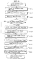
- FIG.14 is a flowchart illustrating the termination process shown in FIG.3B.
- FIG.15 is a chart illustrating a relationship between the reservation time and the charging time according to the first embodiment of the present invention.
- FIG.16 is a conceptual diagram illustrating the mask manufacturing system according to the second embodiment of the present invention.
- FIG.17 is a block diagram illustrating the mask manufacturing system shown in FIG.16.
- FIG.18, FIG.19A, and FIG.19B are flowcharts illustrating the mask manufacturing method according to the second embodiment of the present invention.
- FIG.19C is a flowchart illustrating the termination process shown in FIG.19B.
- FIG.20 is an example of the selection window of the second embodiment of the present invention.
- an LSI mask manufacturing system includes a portal site server 1, a first user terminal 3a, a second user terminal 3b, a third user terminal 3c,a first host terminal 4a having a first lithography unit 5a 1 , a second lithography unit 5a 2 , and a third lithography unit 5a 3 , a second host terminal 4b having a fourth lithography unit 5b 1 , a fifth lithography unit 5b 2 and a sixth lithography unit 5b 3 , a third host terminal 4c having a seventh lithography unit 5c 1 , an eighth lithography unit 5c 2 and a ninth lithography unit 5c 3 , a fourth host terminal 4d having a tenth lithography unit 5d 1 , an eleventh lithography unit 5d 2 and a twelfth lithography unit 5d 3 , and a network 6 connecting the portal site server 1, the user terminals 3a-3c and
- Internet is proposed as one example of network 6.
- other networks such as LAN or a personal computer communication network are alternatives and preferable.
- all of the first host terminal 4a, the second host terminal 4b, the third host terminal 4c, and the fourth host terminal 4d may be connected to network 6 in one country or in a plural countries.
- the first host terminal 4a and the second host terminal 4b are connected to network 6 in Japan
- the third host terminal 4c is connected to network 6 in the U.S.A.
- the fourth host terminal 4d may be connected to network 6 in Germany.
- the portal site server 1 accepts request of the first user terminal 3a, the second user terminal 3b, and the third user terminal 3c, and reserves one of the first lithography unit 5a1 through the twelfth lithography unit 5a12, which is connected to the first host terminal 4a through the fourth host terminal 4d and conforming the user request.
- the first user terminal 3a, the second user terminal 3b, and the third user terminal 3c are possible to communicate with the portal site server 1.
- the portal site server 1 the first user terminal 3a, the second user terminal 3b, and the third user terminal 3c search lithography units, further connected to the first host terminal 4a through the fourth host terminal 4d, and request for a reservation.
- Each of the first lithography unit 5a 1 through the twelfth lithography unit 5d 3 are connected to one of the first host terminal 4a through the fourth host terminal 4d.
- the first host terminal 4a through the fourth host terminal 4d accepts an order of the user from portal site server 1 by using the network 6.
- a completed mask is delivered to the user using a conveyance by land or air.
- Each of the portal site server 1, the first through the third user terminals 3a-3c, the first through fourth host terminal 4a-4d includes CPU, an input device, output device, main memory unit, and an secondary memory (a hard disk). Then, each of the CPU analyzes received message from the network 6 and includes an online control unit, which executes the requested processes. In addition, the CPU also includes a communication control unit to transmit received messages to this online control unit through the network 6. Furthermore, CPU 2, located on the portal site server 1, includes a database management unit. When the inputs and outputs is needed for the user ID database 30, the lithography data database 31, the lithography unit database 32, and the window database 33, the database control unit searches for the place to store files, retrieves requested files and edit the files.
- the portal site server 1 includes an input unit 35, an output unit 36, a main memory 37, an input/output control unit 38, a communication control unit 39, the user ID database 30, the lithography data database 31, the lithography unit database 32, the window database 33, and CPU 2.
- the user ID database 30, the lithography data database 31, the lithography unit database 32 and the window database 33 are stored in the portal site server 1.
- the user ID database 30, the lithography data database 31, the lithography unit database 32 and the window database 33 may be connected through the database servers.
- User ID database 30 stores an identification number given to each user. From the identification number stored in the user ID database 30, it is possible to acquire information where the data is stored.
- the lithography data database 31 is a memory storage to temporary store a lithography data of the LSI masks that the user received from the first through third user terminal 3a - 3c.
- the lithography unit 32 stores the information of each of the lithography unit 5a 1 -5d 3 connected to one of the host terminals 4a-4d, and searches for lithography unit, which meets the user needs.
- the window database 33 is a data storage device to store windows for various services providing at the portal site server 1.
- CPU 2 of portal site server 1 comprises sending unit 9, order receiving unit 10, lithography data receiving unit 11, lithography time prediction unit 12, lithography unit searching unit 13, lithography unit reservation unit 14, lithography configuration unit 15, lithography monitoring unit 16, lithography data deleting unit 17, lithography unit charging unit 18.
- the sending unit 9 selects each window stored in the window database 33 based on a request from the first user terminal 3a through the third user terminal 3c appropriately and sends selected window to one of the user terminals 3a-3c.
- the order receiving unit 10 receives a mask lithography request from the user terminals 3a-3c.
- the lithography data receiving unit 11 receives a lithography data from the user terminals 3a-3c.
- the lithography time prediction unit 12 estimates the time required for a mask lithography in the lithography unit 5x 1 .
- the user determines the reservation time of the lithography unit 5x 1 based on the duration, which the lithography time prediction unit 12 predicted.
- the lithography unit searching unit 13 searches for the most suitable lithography unit 5x 1 based on the lithography conditions received from the user terminals 3a through 3c.
- the lithography unit reservation unit 14 reserves the lithography unit 5x 1 based on the request from the first through third user terminals 3a-3c.
- the lithography configuration unit 15 configures the mask lithography conditions at the lithography unit 5x 1 .
- the user may manually configure the lithography configuration unit 15 by using the first user terminal 3a through the third user terminal 3c.
- the user is also able to select automatically the configurations the lithography conditions.
- the lithography monitoring unit 16 receives lithography state from the lithography unit 5x 1 , and send the lithography states to the first user terminal 3a through the third user terminal 3c.
- the lithography data deleting unit 17 receives the deleting data from the first user terminal 3a through the third user terminal 3c based on the request, and deletes the lithography data stored in the lithography data database 31.
- Lithography unit charging unit 18 charges to the first user terminal 3a through the third user terminal 3c based on an actual time the lithography unit 5x 1 was in use, and clear the mask lithography service provided by the LSI mask lithographing system.
- the input unit 35 may include a key board, a mouse and an optical character reader (OCR) or similar recognition device a graphics input unit such as an image scanner, or a special input unit such as a voice pattern recognition unit, while the output unit 36 may include a display unit such as a liquid crystal display, a cathode ray tube (CRT) display, or a printer such as an ink jet printer or a laser printer.
- OCR optical character reader
- a graphics input unit such as an image scanner
- a special input unit such as a voice pattern recognition unit
- the output unit 36 may include a display unit such as a liquid crystal display, a cathode ray tube (CRT) display, or a printer such as an ink jet printer or a laser printer.
- CTR optical character reader
- printer such as an ink jet printer or a laser printer.
- the input/output control unit (the input/output interface unit) 38 is an interface which connects the input unit 35, output unit 36, reading unit which reads data from storage media such as a compact disk read only memory (CD-ROM), a magnetic optical disk (MO) or a flexible disk (FD), to the CPU 2.
- the main memory 37 includes a read only memory (ROM) and a random access memory (RAM).
- the ROM functions as a program memory for storing programs to be executed in the CPU2.
- the RAM functions as a temporary data memory used as a working area for temporarily storing data used during program execution in the CPU2.
- the communication control device 24 is an interface for connecting with the network 6. Accordingly, this may be, for example, a Terminal Adapter (TA), a dial-up router, or a LAN board. In addition, this may even be data circuit- terminating equipment such as a modem, a digital service unit (DSU), a communication control unit (CCU), or a communication control processor (CCP).
- TA Terminal
- step S23 of FIG.3B As shown in FIG.14, the termination process in step S23 of FIG.3B will be explained.
- the function of the LSI mask manufacturing system and method of the first embodiment of the present invention may be programmed and saved in a computer-readable recording medium.
- the programs saved in the recording medium is transferred to a memory in a computer system and then operated by its operating unit, thus putting the method in practice.
- the recording medium may be selected from semiconductor memories, magnetic disks, optical disks, optomagnetic disks, magnetic tapes, and any of the computer-readable recording mediums.
- the LSI mask manufacturing system, method and program according to the first embodiment of the present invention provides a system, a method and a program that a user can select and control the schedules and the lithography units.
- the LSI mask manufacturing system, method and program according to the first embodiment of the present invention also provides a system, a method and a program that is able to manufacture masks without leaking confidential information, related to lithography data and process conditions for mask manufacturing, to a third person.
- the LSI mask manufacturing system, method and program according to the first embodiment of the present invention also provides a system, a method and a program that is able to reduce the personnel expenses to provide the LSI mask manufacturing system, method and program by introducing an online ordering system.
- the LSI mask manufacturing system, method and program according to the first embodiment of the present invention may also provides a system, a method and a program that is able to reduce costs for mask manufacturing since the user does not have to own units, low in the rate of operation, for a special use or for applying high technologies. The user may share these special units with other users by using the LSI mask manufacturing system, method and program according to the first embodiment of the present invention.
- the LSI mask manufacturing system, method and program according to the first embodiment of the present invention may also provides a system, a method and a program to a wide range of users from small business users to major users (large business users).
- an LSI mask manufacturing system includes a portal site server 1, a first user terminal 3a, a second user terminal 3b, a third user terminal 3c,a first host terminal 4a having a first lithography unit 5a 1 , a second lithography unit 5a 2 , a third lithography unit 5a 3 , a first computer-aided design unit (CAD) 5a 4 and a second CAD 5a 5 , a second host terminal 4b having a fourth lithography unit 5b 1 , a fifth lithography unit 5b 2 and a sixth lithography unit 5b 3 , a third host terminal 4c having a seventh lithography unit 5c 1 , an eighth lithography unit 5c 2 , a ninth lithography unit 5c 3 , a first developing unit5c 4 , a first ashing unit5c 5 , a first mask check unit 5c 6 and a first etching unit 5c 8 , a
- Internet is proposed as one example of network 6.
- other networks such as LAN or a personal computer communication network are alternatives and preferable.
- all of the first host terminal 4a, the second host terminal 4b, the third host terminal 4c, the fourth host terminal 4d, the fifth host terminal 4e and the sixth host terminal 4f may be connected to network 6 in one country or in a plural countries.
- the first host terminal 4a and the second host terminal 4b are connected to network 6 in Japan
- the third host terminal 4c is connected to network 6 in the U.S.A.
- the fourth host terminal 4d may be connected to network 6 in Germany.
- the LSI mask manufacturing system in the second embodiment of the present invention has many structures that the LSI mask manufacturing system in the first embodiment of the present invention shown in FIG.1 and FIG.2. Therefore, only the different structures of the LSI mask manufacturing system in the second embodiment of the present invention will be explained.
- the portal site server 1 in the second embodiment of the present invention is different from the portal site server 1 in the first embodiment shown in FIG.2 since the portal site server 1 in the second embodiment of the present invention has a central processing unit (CPU) 2 including a sending unit 9, a data receiving unit 21, a time prediction unit 22, a mask manufacturing machine searchingunit 23, a mask manufacturing machine reservation unit, a configuration unit 25, a monitoring unit 26, a data deletion unit 27, a charging unit 28 and an ordered range determination unit 29.
- the portal site server 1 of the second embodiment of the present invention includes a mask manufacturing data database 95 and a mask manufacturing unit database 96 as well as an ID database 30 and a window database 33.
- the portal site server 1 of the second embodiment of the present invention is connected to a mask manufacturing related unit group 5 through a network 6.
- the mask manufacturing related unit group 5 has a CAD 5x 2 which generate drawing data for masks from design data, a lithography unit 5x 1 which draws a mask based on a drawing data, a developing unit 5x 3 which develops resist patterns, an ashing unit 5x 4 an etching unit 5x 6 which etches a resist which is a film shielded by chrome or chromic oxide as an etching mask, an ashing unit 5x 4 which ashes the etched resist, a mask check unit 5x 5 which detects for errors on the mask pattern, and an adjustment unit 5x 7 which adjusts the mask pattern.
- the mask manufacturing related unit group may be a machine having one of the above functions or a plural numbers of the above functions.
- the mask manufacturing related unit group may include only the lithography unit 5x 1 , or the mask manufacturing related unit group may include the CAD 5x 2 , the lithography unit 5x 1 , the developing unit 5x 3 , the ashing unit 5x 4 , the mask check unit 5x 5 , the etching unit 5x 6 and the adjustment unit 5x 7 .
- the CAD 5x2 may be a CAD system having various functions such as correcting optic proximity effect, converting data and generating mask layouts.
- the receiving unit 20 receives a mask manufacturing request from the user terminals 3a-3c.
- the data receiving unit 21 receives data and a reservation information from the user terminals 3a-3c.
- the time prediction unit 22 estimates the time required for an ordered process, which is a mask manufacturing. For instance, the time prediction unit 22 estimates design time required at the CAD 5x 2 and lithography time at the lithography unit 5x 1 .
- the mask manufacturing machine searching unit 23 searches for the most suitable machines based on the reservation conditions received from the user terminals 3a-3c, create a list of the possible selection of the machines, and sends the list to the user terminals 3a-3c. For example, if the user select the processes up to the developing process, the mask manufacturing machine searching unit 23 searches for lithography units, CADs and developing units which satisfy the ordered conditions, create a list and sends the list to the user terminals 3a-3c.
- the mask manufacturing machine reservation unit 24 reserves at least one of the mask manufacturing units based on the request from the first through the third user terminals 3a-3c. For instance, when the user specifies the fifth CAD 5e 2 , the fourth lithography unit 5b 1 , the second developing unit 5d 4 , the second ashing unit 5d 3 and the second mask check unit 5d 6 , the mask manufacturing machine reservation unit 24 reserves the fifth CAD 5e 2 , the fourth lithography unit 5b 1 , the second developing unit 5d 4 , the second ashing unit 5d 3 and the second mask check unit 5d 6 for each processes.
- the user does not need to select machines or units from the same host terminal. The user may select machines or units from a plural number of host terminals.
- all of the first host terminal 4a through the sixth host terminal 4f may not be connected to the network 6 in a domestic level, but in an international level.
- the configuration unit 25 configures detailed conditions at each of the units specified by the user. For instance, the user may specify the first CAD 5a 4 and the first lithography unit 5a 1 , and the configuration unit 25 configures detailed conditions at each of the first CAD 5a 4 and the first lithography unit 5a 1 .
- the monitoring unit 26 receives progress reports from each of the units and sends the progress reports to the user terminals 3a-3c. For example, if the user selects the first CAD 5a 4 and the first lithography unit 5a 1 , the monitoring unit 26 receives progress reports from the first CAD 5a 4 and sends the progress reports to the user terminals 3a-3c first. When the design process is finished at the first CAD 5a 4 , the monitoring unit 26 receives progress reports from the first lithography unit 5a 1 and sends the progress reports to the user terminals 3a-3c.
- the data deleting unit 27 receives the deleting data from the user terminals 3a-3c based on the request, and deletes the data sent and stored at each of the specified machines and units.
- the charging unit 28 charges to the user terminals 3a-3c based on an actual time the machines and units are used. Then, the collected charges are paid to owners of the each machines and units.
- the ordered range determination unit 29 determines the ordered range based on received reservation information from the user terminals 3a-3c.
- the mask manufacturing data database 95 is connected to the portal site server 1 and stores data needed for mask manufacturing.
- the "data needed for mask manufacturing” may be data needed for each ordered processes. Therefore, if the ordered process starts from the design process, design specification data is one of the "data needed for mask manufacturing.”
- the mask manufacturing unit database 96 is connected to the portal site server 1 and stores performance information of the first through the third lithography units 5a 1 -5a 3 , the fourth through the sixth lithography unit 5b 1 -5b 3 , the seventh through the ninth lithography unit 5c 1 -5c 3 , the tenth through the twelfth lithography unit 5d 1 -5d 3 , the first CAD 5a 4 , the second CAD 5a 5 , the third CAD 5d 7 , the fourth CAD 5e 1 through the sixth CAD 5e 3 , the seventh CAD 5f 1 through the ninth CAD 5f 3 , the first developing unit 5c 4 , the second developing unit 5d 4 , the first ashing unit 5
- FIG.18 As shown in FIG.18, FIG.19A and FIG.19B, an LSI mask manufacturing method of the second embodiment of the present invention will be explained.
- the function of the LSI mask manufacturing system and method of the second embodiment of the present invention may be programmed and saved in a computer-readable recording medium.
- the programs saved in the recording medium is transferred to a memory in a computer system and then operated by its operating unit, thus putting the method in practice.
- the recording medium may be selected from semiconductor memories, magnetic disks, optical disks, optomagnetic disks, magnetic tapes, and any of the computer-readable recording mediums.
- the LSI mask manufacturing system, method and program according to the second embodiment of the present invention provides a system, a method and a program that a user can select and control the schedules and the lithography units.
- the LSI mask manufacturing system, method and program according to the second embodiment of the present invention also provides a system, a method and a program that is able to manufacture masks without leaking confidential information, related to lithography data and process conditions for LSI mask manufacturing, to a third person.
- the LSI mask manufacturing system, method and program according to the second embodiment of the present invention also provides a system, a method and a program that is able to reduce the personnel expenses to provide an LSI mask manufacturing system by introducing an online ordering system.
- the LSI mask manufacturing system, method and program according to the second embodiment of the present invention may also provide a system, a method and a program that is able to reduce costs for LSI mask manufacturing since the user does not have to own units and machines, although low in the rate of operation, but needed for a special use or for applying high technologies. The user may share these special units with other users by using the LSI mask manufacturing system, method and program according to the first embodiment of the present invention.
- the LSI mask manufacturing system, method and program according to the second embodiment of the present invention may also provide a system, a method and a program to a wide range of users from small business users to major users (large business users).
- the first lithography unit 5a 1 through the third lithography unit 5a 3 , the first CAD 5a 4 , the second CAD 5a 5 , the fourth lithography unit 5b 1 - the sixth lithography unit 5b 3 , the seventh lithography unit 5c 1 - the ninth lithography unit 5c 3 , the first developing unit 5c 4 , the first ashing unit 5c 5 , the first mask check unit 5c 6 , the first etching unit 5c 8 , the tenth lithography unit 5d 1 - the twelfth lithography unit 5d 3 , the second developing unit 5d 4 , the second ashing unit 5d 5 , the second mask check unit 5d 6 , the third CAD 5d 7 , the second etching unit 5d 8 , the adjustment unit 5d 9 , the fourth CAD 5e 1 - the sixth CAD 5e 3 and the seventh CAD 5f 1 - the ninth CAD 5f 3 may be connected to the first through the sixth host terminal
- the first host terminal 4a through the sixth host terminal 4f may be connected to the network 6 in domestic level or in the international level. In other words, some of the host terminals may be connected to the network 6 in different countries.
Abstract
Description
- This application is based upon and claims the benefit of priority from prior Japanese Patent Application P2002-090029 filed on March 27, 2002; the entire contents of which are incorporated by reference herein.
- The present invention relates to methods, systems and programs for manufacturing masks of a large scale integrated (LSI) system.
- Generally, masks or reticles are needed to be produced depending on each semiconductor manufacturing process. Therefore, first, mask data, corresponding to each of a plural number of masks, are generated by using a computer-aided design (CAD) system based on design of an LSI. Then, masks that can be put on top of one another are generated by using a pattern generator, such as an electron beam writer, and a mask set is completed. Furthermore, each of the masks is checked. Finally, the masks, after the examination, are going to be used in a semiconductor manufacturing process.
- Generally, customers, such as semiconductor manufacturing makers and semiconductor foundry, specifies a mask specification, specific numbers, and delivery time to order masks to a mask house, and the mask house delivers masks before the delivery time. However, in such a conventional mask manufacturing methods and system, all the selection of a schedule and machines (such as pattern generators) is entrusted to a decision of the mask manufacturing house side, where a customer is not able to choose any schedule or machines. Thus, it has been difficult for the manufacturer to prepare masks urgently when the mask design has changed or other things happen.
- In addition, conventional method and system for procuring masks are provided for big customers, who order and entrust a large quantity of mask manufacturing. Therefore, small customers, who order a small quantity of mask manufacturing, are difficult to order, and they may loose business chances.
- Furthermore, there is a security problem concerning a mask manufacturing. Therefore, masks to be manufactured in an absolute secrecy in the research and development may not be possible in the conventional mask manufacturing method and system. In addition, in a mask house, a factor for raising a cost price of a semiconductor manufacturing is personnel expenses for operating manufacturing devices in a plural number of places (or sites).
- An LSI mask manufacturing system includes: a network; a portal site server configured to be connected to the network; a user terminal configured to be connected to the portal site server; a host terminal configured to be connected to the network; and a lithography units configured to be connected to the host terminal.
- An LSI mask manufacturing system, includes: a network; a portal site server configured to be connected to the network; a user terminal configured to connected to the portal site server; a host terminal configured to connected to the network; and a mask manufacturing unit configured to connected to the host terminal.
- A computer implemented method for LSI mask manufacturing includes : storing performance information of a lithography unit, connected to a network, in a lithography unit database; receiving a lithography data and a lithography reservation condition from a user terminal connected to the network; storing the lithography data in a lithography data database; searching for a lithography unit matching to the lithography reservation condition, generating a list of lithography units, and sending the list to the user terminal; and receiving information of a lithography unit specified by the user terminal and sending a lithography request to the lithography unit specified by the user terminal.
- A computer implemented method for LSI mask manufacturing, the method includes: storing performance information of a mask manufacturing unit, connected to a network, in a mask manufacturing unit database; receiving data and a reservation condition from a user terminal connected to the network; storing the data in a mask manufacturing data database; determining a ordered range based on the reservation condition; searching for a mask manufacturing unit marching to the reservation condition, generating a list of mask manufacturing units, and sending the list to the user terminal; and receiving information of a mask manufacturing unit specified by the user terminal and sending a request to the mask manufacturing unit specified by the user terminal.
- A computer program product for use with a mask manufacturing unit, the computer program product includes: instructions to store performance information of a lithography unit, connected to a network, in a lithography unit database; instructions to receive a lithography data and a lithography reservation condition from a user terminal connected to the network; instructions to store the lithography data in a lithography data database; instructions to search for a lithography unit matching to the lithography reservation condition, generate a list of lithography units, and send the list to the user terminal; and instructions to receive information of a lithography unit specified by the user terminal and send a lithography request to the lithography unit specified by the user terminal.
- A computer program product for use with a mask manufacturing unit the computer program product includes: instructions to store performance information of a mask manufacturing unit, connected to a network, in amaskmanufacturing unit database; instructions to receive data and a reservation condition from a user terminal connected to the network; instructions to store the data in a mask manufacturing data database; instructions to determine a ordered range based on the reservation condition; instructions to search for a mask manufacturing unit matching to the reservation condition, generate a list of mask manufacturing units, and send the list to the user terminal; and instructions to receive information of a mask manufacturing unit specified by the user terminal and send a request to the mask manufacturing unit specified by the user terminal.
- FIG.1 is a conceptual diagram illustrating the LSI mask manufacturing system according to the first embodiment of the present invention.
- FIG.2 is a block diagram illustrating a
portal site server 1 shown in FIG.1. - FIG.3A and FIG.3B are flowcharts illustrating the LSI mask manufacturing method according to the first embodiment of the present invention.
- FIG.4 is a flowchart illustrating a lithography data forwarding process shown in FIG.3B.
- FIG.5 is an example of the forwarding process window of the first embodiment of the present invention.
- FIG. 6 is a flowchart illustrating a lithography reservation process shown in FIG.3B.
- FIG.7 is an example of the lithography unit reservation window of the first embodiment of the present invention.
- FIG.8 is an example of the time prediction process window of the first embodiment of the present invention.
- FIG.9 is an example of the search result display window of the first embodiment of the present invention.
- FIG.10 is a flowchart illustrating a configuration process shown in FIG.3B.
- FIG.11 is an example of the lithography starting up menu of the first embodiment of the present invention.
- FIG.12 is a flowchart illustrating the monitoring process shown in FIG.3B.
- FIG.13 is an example of the lithography state monitoring window of the first embodiment of the present invention.
- FIG.14 is a flowchart illustrating the termination process shown in FIG.3B.
- FIG.15 is a chart illustrating a relationship between the reservation time and the charging time according to the first embodiment of the present invention.
- FIG.16 is a conceptual diagram illustrating the mask manufacturing system according to the second embodiment of the present invention.
- FIG.17 is a block diagram illustrating the mask manufacturing system shown in FIG.16.
- FIG.18, FIG.19A, and FIG.19B are flowcharts illustrating the mask manufacturing method according to the second embodiment of the present invention.
- FIG.19C is a flowchart illustrating the termination process shown in FIG.19B.
- FIG.20 is an example of the selection window of the second embodiment of the present invention.
- Various embodiments of the present invention will be described with reference to the accompanying drawings. It is to be noted that the same or similar reference numerals are applied to the same or similar parts and elements throughout the drawings, and the description of the same or similar parts and elements will be omitted or simplified.
- In the following descriptions, numerous specific details are set fourth such as specific signal values, etc. to provide a thorough understanding of the present invention. However, it will be obvious to those skilled in the art that the present invention may be practiced without such specific details in other instances, well-known circuits have been shown in block diagram form in order not to obscure the present invention in unnecessary detail.
- As shown in FIG.1 and FIG.2, an LSI mask manufacturing system according to the first embodiment of the present invention includes a
portal site server 1, afirst user terminal 3a, asecond user terminal 3b, athird user terminal 3c,afirst host terminal 4a having a first lithography unit 5a1, a second lithography unit 5a2, and a third lithography unit 5a3, asecond host terminal 4b having a fourth lithography unit 5b1, a fifth lithography unit 5b2 and a sixth lithography unit 5b3, athird host terminal 4c having a seventh lithography unit 5c1, an eighth lithography unit 5c2 and a ninth lithography unit 5c3, afourth host terminal 4d having a tenth lithography unit 5d1, an eleventh lithography unit 5d2 and a twelfth lithography unit 5d3, and anetwork 6 connecting theportal site server 1, theuser terminals 3a-3c and thehost terminals 4a-4d. - In the first embodiment of the present invention, Internet is proposed as one example of
network 6. However, other networks such as LAN or a personal computer communication network are alternatives and preferable. In addition, all of thefirst host terminal 4a, thesecond host terminal 4b, thethird host terminal 4c, and thefourth host terminal 4d may be connected tonetwork 6 in one country or in a plural countries. For example, it is possible to do that thefirst host terminal 4a and thesecond host terminal 4b are connected tonetwork 6 in Japan, thethird host terminal 4c is connected tonetwork 6 in the U.S.A., and thefourth host terminal 4d may be connected tonetwork 6 in Germany. - The
portal site server 1 accepts request of thefirst user terminal 3a, thesecond user terminal 3b, and thethird user terminal 3c, and reserves one of the first lithography unit 5a1 through the twelfth lithography unit 5a12, which is connected to thefirst host terminal 4a through thefourth host terminal 4d and conforming the user request. Thefirst user terminal 3a, thesecond user terminal 3b, and thethird user terminal 3c are possible to communicate with theportal site server 1. Through theportal site server 1, thefirst user terminal 3a, thesecond user terminal 3b, and thethird user terminal 3c search lithography units, further connected to thefirst host terminal 4a through thefourth host terminal 4d, and request for a reservation. Each of the first lithography unit 5a1 through the twelfth lithography unit 5d3 are connected to one of thefirst host terminal 4a through thefourth host terminal 4d. Thefirst host terminal 4a through thefourth host terminal 4d accepts an order of the user fromportal site server 1 by using thenetwork 6. A completed mask is delivered to the user using a conveyance by land or air. - Each of the
portal site server 1, the first through thethird user terminals 3a-3c, the first throughfourth host terminal 4a-4d includes CPU, an input device, output device, main memory unit, and an secondary memory (a hard disk). Then, each of the CPU analyzes received message from thenetwork 6 and includes an online control unit, which executes the requested processes. In addition, the CPU also includes a communication control unit to transmit received messages to this online control unit through thenetwork 6. Furthermore,CPU 2, located on theportal site server 1, includes a database management unit. When the inputs and outputs is needed for theuser ID database 30, thelithography data database 31, thelithography unit database 32, and thewindow database 33, the database control unit searches for the place to store files, retrieves requested files and edit the files. - As is shown in FIG.2, the
portal site server 1 includes aninput unit 35, anoutput unit 36, amain memory 37, an input/output control unit 38, acommunication control unit 39, theuser ID database 30, thelithography data database 31, thelithography unit database 32, thewindow database 33, andCPU 2. Theuser ID database 30, thelithography data database 31, thelithography unit database 32 and thewindow database 33 are stored in theportal site server 1. In addition, theuser ID database 30, thelithography data database 31, thelithography unit database 32 and thewindow database 33 may be connected through the database servers. -
User ID database 30 stores an identification number given to each user. From the identification number stored in theuser ID database 30, it is possible to acquire information where the data is stored. Thelithography data database 31 is a memory storage to temporary store a lithography data of the LSI masks that the user received from the first throughthird user terminal 3a - 3c. Thelithography unit 32 stores the information of each of the lithography unit 5a1-5d3 connected to one of thehost terminals 4a-4d, and searches for lithography unit, which meets the user needs. Thewindow database 33 is a data storage device to store windows for various services providing at theportal site server 1. - Furthermore,
CPU 2 ofportal site server 1 comprises sendingunit 9,order receiving unit 10, lithographydata receiving unit 11, lithographytime prediction unit 12, lithographyunit searching unit 13, lithographyunit reservation unit 14,lithography configuration unit 15,lithography monitoring unit 16, lithographydata deleting unit 17, lithographyunit charging unit 18. - The sending
unit 9 selects each window stored in thewindow database 33 based on a request from thefirst user terminal 3a through thethird user terminal 3c appropriately and sends selected window to one of theuser terminals 3a-3c. Theorder receiving unit 10 receives a mask lithography request from theuser terminals 3a-3c. The lithographydata receiving unit 11 receives a lithography data from theuser terminals 3a-3c. The lithographytime prediction unit 12 estimates the time required for a mask lithography in the lithography unit 5x1. The user determines the reservation time of the lithography unit 5x1 based on the duration, which the lithographytime prediction unit 12 predicted. The lithographyunit searching unit 13 searches for the most suitable lithography unit 5x1 based on the lithography conditions received from theuser terminals 3a through 3c. The lithographyunit reservation unit 14 reserves the lithography unit 5x1 based on the request from the first throughthird user terminals 3a-3c. Thelithography configuration unit 15 configures the mask lithography conditions at the lithography unit 5x1. In addition, the user may manually configure thelithography configuration unit 15 by using thefirst user terminal 3a through thethird user terminal 3c. In addition, the user is also able to select automatically the configurations the lithography conditions. Thelithography monitoring unit 16 receives lithography state from the lithography unit 5x1, and send the lithography states to thefirst user terminal 3a through thethird user terminal 3c. The lithographydata deleting unit 17 receives the deleting data from thefirst user terminal 3a through thethird user terminal 3c based on the request, and deletes the lithography data stored in thelithography data database 31. Lithographyunit charging unit 18 charges to thefirst user terminal 3a through thethird user terminal 3c based on an actual time the lithography unit 5x1 was in use, and clear the mask lithography service provided by the LSI mask lithographing system. - The
input unit 35 may include a key board, a mouse and an optical character reader (OCR) or similar recognition device a graphics input unit such as an image scanner, or a special input unit such as a voice pattern recognition unit, while theoutput unit 36 may include a display unit such as a liquid crystal display, a cathode ray tube (CRT) display, or a printer such as an ink jet printer or a laser printer. - The input/output control unit (the input/output interface unit) 38 is an interface which connects the
input unit 35,output unit 36, reading unit which reads data from storage media such as a compact disk read only memory (CD-ROM), a magnetic optical disk (MO) or a flexible disk (FD), to theCPU 2. Themain memory 37 includes a read only memory (ROM) and a random access memory (RAM). The ROM functions as a program memory for storing programs to be executed in the CPU2. The RAM functions as a temporary data memory used as a working area for temporarily storing data used during program execution in the CPU2. Thecommunication control device 24 is an interface for connecting with thenetwork 6. Accordingly, this may be, for example, a Terminal Adapter (TA), a dial-up router, or a LAN board. In addition, this may even be data circuit- terminating equipment such as a modem, a digital service unit (DSU), a communication control unit (CCU), or a communication control processor (CCP). - As shown in FIG.3A and FIG.3B, the LSI mask lithographing method of the first embodiment of the present invention will be explained.
- (a) First, in step 8 of FIG.3A, the
portal site server 1 receives the detailed performance information of the lithography unit from each of the first to the twelfth lithography unit 5a1-5d3, connected to one of the first to the fourth host terminals. Then, in step S9, theportal site server 1 stores the detailed performance information of the first to the twelfth lithography unit 5a1-5d3 in thelithography unit database 32. In step S10, it is determined whether or not there is a next lithography unit, and when there is the next lithography unit, which thelithography unit database 32 does not yet receives performance information, processes from step S8 to step S10 are repeated. If thelithography unit database 32 receives all of the performance information of the lithography unit, the receiving process of the lithography unit is finished, and the process proceeds to a process in step S11. - (b) In step S11 of FIG.3B, the
portal site server 1 accepts a connection request from one of the first through thethird user terminal 3a-3c. In the first embodiment of the present invention, theportal site server 1 accepts connection from thefirst user terminal 3a in order to make the description easier. Then, in step S12, the sendingunit 9 of theportal site server 1 transmits a service selection window to thefirst user terminal 3a. In this service selection window, the user may select a service, such as a forwarding lithography data (S15), lithography reservation (S17), lithography condition configuration (S19), lithography monitoring (S21), and the termination process (s23), through thefirst user terminal 3a. In step S13, theorder receiving unit 10 receives a user selected service information from thefirst user terminal 3a, and executes the user selected service. - (c) In step S14, the
portal site server 1 determines whether or not the selected information in step S13 is forwarding of the lithography data. If it is the forwarding of the lithography data, the process proceeds to the process in step S15, and starts the lithography data forwarding process. Then, theportal site server 1 also executes the process for receiving the lithography data sent from thefirst user terminal 3a. If it is not the forwarding of the lithography data, the process proceeds to step S16. - (d) In step S16, the
portal site server 1 determines whether or not it is the selected information received in step S13. If it is the lithography reservation, the process proceeds to step S17, a lithography reservation process is started, and the reservation process of the lithography unit is executed based on the request of thefirst user terminal 3a. If it is not the lithography reservation, process proceeds to step S18. - (e) In step S18, the
portal site server 1 determines whether or not the selected information is the configuration of the lithography conditions. If it is the lithography condition configuration, the process proceeds to step S19, and the lithography condition configuration process of the lithography unit 5x1 is executed based on the request from thefirst user terminal 3a. If it is not the lithography condition configuration, the process proceeds to step S20. - (f) In the step S20, the
portal site server 1 determines whether or not the selected information received in step S13 is the lithography monitoring or not. If it is the lithography monitoring, process proceeds to step S21, and the lithography monitoring process, where the lithography state at the lithography unit 5x1 is sent to thefirst user terminal 3a, is executed. - (g) In step S22, the
portal site server 1 determines whether or not the selected information received in step S13 is the termination process. If it is the termination process, the process proceeds to step S23, and lithography data is deleted based on thefirst user terminal 3a. If it is not the termination process, theportal site server 1 disconnects thefirst user terminal 3a and ends the process. -
- As shown in Fig.4, a process for forwarding lithography data in step S15 of FIG.3B will be explained.
- (a) When the selection information, received by the
first user terminal 3a, is the "forwarding lithography data" in step S13 of FIG.3B, theportal site server 1 starts a forwarding lithography data process in step S104 of FIG.4. - (b) In step S105, sending
unit 9 sends a forwardingwindow 41 to thefirst user terminal 3a. An example of the forwardingwindow 41 is shown in FIG.5. In the forwardingwindow 41, auser ID 51, given for each of the users, is displayed. Then, the user may specify a directory of the portal site server as aserver directory 52. In the forwardingwindow 41 shown in FIG.5 shows that a user directory in a top directory of theportal site server 1 is specified. The user may also specify a mask data file(s) for mask pattern inpattern data 53. In FIG.5, two files such as a "patternFile 1" and "patternFile 2" are specified as thepattern data 53. Inlayout data 54, a file or files for layout data, such as a pattern layout, an alignment mark pattern and a mark position may be specified. In FIG.5, two files such as a "layoutFile and a "layoutFile2" are selected as thelayout data 54. In amark library 55, a library for a mark or marks generally used for an alignment mark pattern and a measurement may be specified. In adrawing recipe 56, a recipe file or recipe files, including parameters for set-up conditions and exposure conditions that the user would like to control. Then, in anencryption 57, the user may select to send the specified data whether or not encrypted. - (c) When the data (in
server directory 52 through the encryption 57) are selected and sent from thefirst user terminals 3a to theportal site server 1, theportal site server 1 receives a requested data, including the pattern data, by using the lithographydata receiving unit 11, stores in thelithography data database 31, and ends the process for forwarding lithography data. -
- As shown in FIG.6, the reservation process in step S17 of FIG.3B will be explained.
- (a) When "lithography reservation" is selected in step S13
of FIG.3B, the
portal site server 1 starts the reservation process in step S114 of FIG.6. Then, in step S115, the sendingunit 9 sends areservation window 42 to thefirst user terminal 3a. An example of thereservation window 42 is shown in FIG. 7. First, in thereservation window 42, auser ID 51 is displayed. Then, at a requestedsite 58, the user may specify and request a site, where the lithography units are connected. In addition, at anitem 58b, the user may also specify "priority" which has some flexibility or "fixed" which does not have any flexibility. In FIG.7, a site called "Domestic B" is selected and listed as asite name 58a, and in theitem 58b, "priority" is specified. Therefore, in the example shown in FIG.7, a domestic site B is specified to be selected as prioritized. Although it is not shown in FIG.7, an item to select a lithography unit may be possibly placed in thereservation window 42. - (b) As a lithography type (electron beam (EB)/laser) 59,
an electron beam (EB) exposure or a laser exposure may be selected
at an
item 59a. Then, in anitem 59b "priority" or "fixed" may also be selected. In addition, a wavelength for the laser may be indirectly selected at adrawing resolution 59c. A size and number of masks may also be specified in thereservation window 42. A mask size may be typed in inches at anitem 60a, and numbers of masks may also be typed in at anitem 60b. Then, the user may specify a requestedstart time 61 and a requestedend time 62, and the user may set up areservation time 63. As thereservation time 63, fixed time in anitem 63a may be set up, but the user may set up a drawing time prediction process at anitem 63b to predict a lithography time and use this predicted time as the reservation time. - (c) When all of the items in the
reservation window 42 are filled up, a reservation data is sent from thefirst user terminal 3a to theportal site server 1, and theportal site server 1 receives the reservation data in a step S116 of FIG.6. - (d) Then, in step S117, the
portal site server 1 determines whether or not anitem 63b, the drawing time prediction, is selected. If the drawing time prediction is not selected, process proceeds to step S120. If the drawing time prediction is selected, the sendingunit 9 sends a timeprediction process window 43 to thefirst user terminal 3a in step S118. The timeprediction process window 43 is shown in FIG.8. As shown in FIG.8, in the timeprediction process window 43, theuser ID 51 is displayed first, as other windows explained above do. Then, items, such as thepattern data 53, thelayout data 54, themark library 55, thedrawing recipe 56,mask size 60a, andmask numbers 60b are displayed. In anitem 64a, the user may select whether or not to execute an EB proximity effect correction, and the user may also select a type in anitem 64b when the user selects to execute EB proximity effect correction. In an example shown in FIG.8, the user selects to execute the EB proximity effect correction, and its type is a dose amount correction. When the user fills up all of the information, thefirst user terminal 3a sends data for the time prediction to theportal site server 1. - (e) In step S119, the
portal site server 1 receives the data for the time prediction from thefirst user terminal 3a. Then, in step S120, the lithographytime prediction unit 12 executes the lithography reservation process. In step S121, the lithographyunit searching unit 13 searches for at least a lithography unit 5x1 as a candidate lithography unit. - (f) In step S122, the
portal site server 1 sends a searchresult display window 44, which includes a list of searched result in step S120, to thefirst user terminal 3a. An example of the searchresult display window 44 is shown in FIG.9. As shown in FIG.9, theuser ID 51 is displayed in the searchresult display window 44. Further, the searchresult display window 44 shows a list including asite name 65a, aunit name 65b, atype name 65c, aresolution 65d, a startingtime 65e, a predictedtime 65f, alithography price 65g for each of the lithography units that match to the conditions given by the user. Then, the user selects one lithography unit, such as the lithography unit 5x1. Then, the user reserves the lithography unit 5x1 as a candidate by selecting areservation number 66 in the searchresult display window 44 at thefirst user terminal 3a. In FIG.9, the user select "1" for thereservation number 66. It means that the user select the first lithography unit shown in the searchresult display window 44. Corresponding to this user's action, theportal site server 1 receives the selected data from thefirst user terminal 3a in step S123. - (g) In step S124, the lithography
unit reservation unit 14 sends reservation information to the lithography unit 5x1, which is selected by the user, and theportal site server 1 ends the reservation process (S17). -
- As shown in FIG. 10, the lithography condition configuration process in step S19 of FIG.3B will be explained.
- (a) When the "configuration process (S19)" is selected by
the user, the
portal site server 1 sends a lithography starting upmenu 45 to thefirst user terminal 3a in step S134 of FIG.10. In the lithography starting upmenu 45, as shown in FIG.11, theuser ID 51 is displayed. The user may use thefirst terminal 3a to select or input information, such as apattern data 53, alayout data 54, amark library 55, adrawing recipe 56, areservation number 66a, aunit operation mode 60b, and a reservation time (start time) 67. In FIG.11, "patternFilel" and "patternFile2" stored in a directory, called "draw1" in are selected as thepattern data 53. As thelayout data 54, "layoutFile1" and "layoutFile2" in the "draw1" are selected. As themark library 55, "mark_lib" in the "draw1" is selected. As thedrawing recipe 56, "draw_recipe" in the "draw1" is selected. Thereservation number 66a is "1", and theunit operating mode 60b is set up to the "manual" mode. Then, the reserved (start)time 67 is set up at "10 am on June 3, 2001" in FIG.11. - (c) In step S135, the
portal site server 1 receives the starting up data, which the user input to the lithography starting upmenu 45, from theuser terminal 3a. Then, in step S136, theportal site server 1 certifies if theunit operating mode 60b is selected "manual" or "automatic" for specifying whether or not a "prior operation" is selected. If theunit operating mode 60b is in a "manual" mode, the "prior operation" is selected, and theportal site server 1 sends a lithography condition configuration window to thefirst user terminal 3a in step S138. Then, in step S139, theportal site server 1 receives a configuration data from thefirst user terminal 3a. If theunit operating mode 60b is in an "automatic" mode, the "prior operation" is not selected, so the process proceeds to a process in step S137, and theportal site server 1 configures the lithography condition. Then, the process proceeds to a process in Step S140. - (d) In step S140, the
portal site server 1 connects to the lithography unit 5x1, selected by the user. Then, in step S141, theportal site server 1 sends the configuration data, manually or automatically configured, to the lithography unit 5x1. The lithography unit 5x1 receives the configuration data and starts the lithography process at the reserved time based on the configuration data. During the lithography process, theportal site server 1 receives lithography progress reports from the lithography unit 5x1. -
- As shown in FIG.12, the lithography monitoring process in step S21 of FIG.3B will be explained.
- (a) In step S142 shown in FIG.12, the
lithography monitoring unit 16 receives the lithography progress reports from the lithography unit 5x1. Then, in step S143, thelithography monitoring unit 16 sends the lithography progress reports to thefirst user terminal 3a within a lithographystate monitoring window 46, shown in FIG. 13. In the lithographystate monitoring window 46, the user may figure out which mask is in which process, or how far the process goes on at the present time. In this lithographystate monitoring window 46, theuser ID 51, a startingtime 68, a predicted endingtime 69, anitem 70a to show which mask is on the process, an orderedmask number 70b, anitem 71a showing a progress statement within a proportion of a lithography area (an item illustrating a progress state of the mask lithography in a proportion of a lithography area), anitem 71b showing a progress statement within a frame number, and agraphic monitor 72 are displayed. In thegraphic monitor 72, the lithography process is divided into a plural number of processes or variety. Therefore, the user may easily understand how far the process goes. In thegraphic monitor 72, shown in FIG.13, the lithography process is divided into eight control systems, such as a beam-deflection system 73, alaser measuring system 74, anelectron beam generator 75, aspecimen chamber 75a, astage driving system 76, avacuum pumping system 77, anelectronic control system 78 and acontrol computer 79. When all of the ordered masks go on the process and the mask drawing ends, the process proceeds to a process in step S144. - (b) In step S144, the
portal site server 1 determines whether or not the lithography process ends. If the lithography process does not end, the process goes back to a process in step S142 and continues to receive the lithography state from the lithography unit 5x1. If the lithography process ends, the configuration data, sent to the lithography unit 5x1 as ordered information, is deleted. However, theportal site server 1 still has the configuration data. Therefore, the lithography unit 5x1 may receive the configuration data when something happens and the lithography unit 5x1 needs deleted data. Therefore, in order to cope with a security problem, all of the data, sent from thefirst user terminal 3a and temporally stored in the lithography unit 5x1, is completely deleted. -
- As shown in FIG.14, the termination process in step S23 of FIG.3B will be explained.
- (a) First, when the "termination process" in step S13 FIG. 3B
is selected, the sending
unit 9 sends a deleting data window to thefirst user terminal 3a in step S154 of FIG.14. The user may select data to delete and input information about the deleting data on the deleting data window. Then, theportal site server 1 receives the information about the deleting data from thefirst user terminal 3a. - (b) In step S156, the lithography
data deleting unit 17 destroys the deleting data based on received information about the deleting data from thefirst user terminal 3a. This deleting data is data stored in theportal site server 1 and sent to the lithography unit 5x1, which the user selected. The data sent and stored in the lithography unit 5x1 is destroyed when the lithography process is done at the lithography unit 5x1. - (c) When the deleting process of data is ended, the
lithography charging unit 18 sends a transaction window to thefirst user terminal 3a and charges the user for use of the lithography unit 5x1. The user is generally charged to an actual time that the lithography unit 5x1 is in use. For example, as shown in FIG.15, when the lithography reservation is made, areserved time 85 is calculated by adding amargin time 83 to an expecteddrawing time 82. Then, after this drawing, only an actual time, that the lithography unit 5x1 is in use, is charged. For instance, acase 1 in FIG.15 shows that time up to anending time 86 is going to be charged. Acase 2 shows that anexcess time 84 is going to be exempted when the reserved time is exceeded. In other words, in thecase 2, although the time required includes the expecteddrawing time 82,margin 83, and theexcess time 84 in FIG.15, a maximum charging time is only the reserved time and theexcess time 84, which is a payment exempted time, is exempted. When the time prediction process is in use, theexcess time 84 is exempted from charging time for reducing inaccuracy of the time prediction. - (d) In step S158, the
portal site server 1 receives a transaction data from thefirst user terminal 3a and ends the termination process of step S23 in FIG.3B. -
- The function of the LSI mask manufacturing system and method of the first embodiment of the present invention may be programmed and saved in a computer-readable recording medium. For the LSI mask manufacturing method of the first embodiment of the present invention, the programs saved in the recording medium is transferred to a memory in a computer system and then operated by its operating unit, thus putting the method in practice. The recording medium may be selected from semiconductor memories, magnetic disks, optical disks, optomagnetic disks, magnetic tapes, and any of the computer-readable recording mediums.
- The LSI mask manufacturing system, method and program according to the first embodiment of the present invention provides a system, a method and a program that a user can select and control the schedules and the lithography units. In addition, the LSI mask manufacturing system, method and program according to the first embodiment of the present invention also provides a system, a method and a program that is able to manufacture masks without leaking confidential information, related to lithography data and process conditions for mask manufacturing, to a third person. Furthermore, the LSI mask manufacturing system, method and program according to the first embodiment of the present invention also provides a system, a method and a program that is able to reduce the personnel expenses to provide the LSI mask manufacturing system, method and program by introducing an online ordering system. In addition, the LSI mask manufacturing system, method and program according to the first embodiment of the present invention may also provides a system, a method and a program that is able to reduce costs for mask manufacturing since the user does not have to own units, low in the rate of operation, for a special use or for applying high technologies. The user may share these special units with other users by using the LSI mask manufacturing system, method and program according to the first embodiment of the present invention. In addition, the LSI mask manufacturing system, method and program according to the first embodiment of the present invention may also provides a system, a method and a program to a wide range of users from small business users to major users (large business users).
- As shown in FIG.16, an LSI mask manufacturing system according to the second embodiment of the present invention includes a portal site server 1, a first user terminal 3a, a second user terminal 3b, a third user terminal 3c,a first host terminal 4a having a first lithography unit 5a1, a second lithography unit 5a2, a third lithography unit 5a3, a first computer-aided design unit (CAD) 5a4 and a second CAD 5a5, a second host terminal 4b having a fourth lithography unit 5b1, a fifth lithography unit 5b2 and a sixth lithography unit 5b3, a third host terminal 4c having a seventh lithography unit 5c1, an eighth lithography unit 5c2, a ninth lithography unit 5c3, a first developing unit5c4, a first ashing unit5c5, a first mask check unit 5c6 and a first etching unit 5c8, a fourth host terminal 4d having a tenth lithography unit 5d1, an eleventh lithography unit 5d2 and a twelfth lithography unit 5d3, a second developing unit 5d4, a second ashing unit 5d5, a second mask check unit 5d6, a third CAD 5d7, a second etching unit 5d8 and an adjustment unit 5d9, a fifth host terminal 4e having a fourth CAD 5e1, a fifth CAD 5e2 and a sixth CAD 5e3, a sixth host terminal 4f having a seventh CAD 5f1, a eighth CAD 5f2 and a ninth CAD 5f3, and a network 6 connecting the portal site server 1, the user terminals 3a-3c, and the host terminals 4a-4f.
- In the second embodiment of the present invention, Internet is proposed as one example of
network 6. However, other networks such as LAN or a personal computer communication network are alternatives and preferable. In addition, all of thefirst host terminal 4a, thesecond host terminal 4b, thethird host terminal 4c, thefourth host terminal 4d, thefifth host terminal 4e and thesixth host terminal 4f may be connected tonetwork 6 in one country or in a plural countries. For example, it is possible to do that thefirst host terminal 4a and thesecond host terminal 4b are connected tonetwork 6 in Japan, thethird host terminal 4c is connected tonetwork 6 in the U.S.A., and thefourth host terminal 4d may be connected tonetwork 6 in Germany. - As shown in FIG.16 and FIG.17, the LSI mask manufacturing system in the second embodiment of the present invention has many structures that the LSI mask manufacturing system in the first embodiment of the present invention shown in FIG.1 and FIG.2. Therefore, only the different structures of the LSI mask manufacturing system in the second embodiment of the present invention will be explained. As shown in FIG.17, the
portal site server 1 in the second embodiment of the present invention is different from theportal site server 1 in the first embodiment shown in FIG.2 since theportal site server 1 in the second embodiment of the present invention has a central processing unit (CPU) 2 including a sendingunit 9, adata receiving unit 21, atime prediction unit 22, a maskmanufacturing machine searchingunit 23, a mask manufacturing machine reservation unit, a configuration unit 25, amonitoring unit 26, adata deletion unit 27, a chargingunit 28 and an orderedrange determination unit 29. In addition, theportal site server 1 of the second embodiment of the present invention includes a maskmanufacturing data database 95 and a maskmanufacturing unit database 96 as well as anID database 30 and awindow database 33. Further more, theportal site server 1 of the second embodiment of the present invention is connected to a mask manufacturing relatedunit group 5 through anetwork 6. The mask manufacturing relatedunit group 5 has a CAD 5x2 which generate drawing data for masks from design data, a lithography unit 5x1 which draws a mask based on a drawing data, a developing unit 5x3 which develops resist patterns, an ashing unit 5x4 an etching unit 5x6 which etches a resist which is a film shielded by chrome or chromic oxide as an etching mask, an ashing unit 5x4 which ashes the etched resist, a mask check unit 5x5 which detects for errors on the mask pattern, and an adjustment unit 5x7 which adjusts the mask pattern. Then the mask manufacturing related unit group may be a machine having one of the above functions or a plural numbers of the above functions. For instance, the mask manufacturing related unit group may include only the lithography unit 5x1, or the mask manufacturing related unit group may include the CAD 5x2, the lithography unit 5x1, the developing unit 5x3, the ashing unit 5x4, the mask check unit 5x5, the etching unit 5x6 and the adjustment unit 5x7. Further more, the CAD 5x2 may be a CAD system having various functions such as correcting optic proximity effect, converting data and generating mask layouts. - The receiving
unit 20 receives a mask manufacturing request from theuser terminals 3a-3c. Thedata receiving unit 21 receives data and a reservation information from theuser terminals 3a-3c. Thetime prediction unit 22 estimates the time required for an ordered process, which is a mask manufacturing. For instance, thetime prediction unit 22 estimates design time required at the CAD 5x2 and lithography time at the lithography unit 5x1. The mask manufacturingmachine searching unit 23 searches for the most suitable machines based on the reservation conditions received from theuser terminals 3a-3c, create a list of the possible selection of the machines, and sends the list to theuser terminals 3a-3c. For example, if the user select the processes up to the developing process, the mask manufacturingmachine searching unit 23 searches for lithography units, CADs and developing units which satisfy the ordered conditions, create a list and sends the list to theuser terminals 3a-3c. - The mask manufacturing
machine reservation unit 24 reserves at least one of the mask manufacturing units based on the request from the first through thethird user terminals 3a-3c. For instance, when the user specifies the fifth CAD 5e2, the fourth lithography unit 5b1, the second developing unit 5d4, the second ashing unit 5d3 and the second mask check unit 5d6, the mask manufacturingmachine reservation unit 24 reserves the fifth CAD 5e2, the fourth lithography unit 5b1, the second developing unit 5d4, the second ashing unit 5d3 and the second mask check unit 5d6 for each processes. The user does not need to select machines or units from the same host terminal. The user may select machines or units from a plural number of host terminals. In addition, all of thefirst host terminal 4a through thesixth host terminal 4f may not be connected to thenetwork 6 in a domestic level, but in an international level. - The configuration unit 25 configures detailed conditions at each of the units specified by the user. For instance, the user may specify the first CAD 5a4 and the first lithography unit 5a1, and the configuration unit 25 configures detailed conditions at each of the first CAD 5a4 and the first lithography unit 5a1. The
monitoring unit 26 receives progress reports from each of the units and sends the progress reports to theuser terminals 3a-3c. For example, if the user selects the first CAD 5a4 and the first lithography unit 5a1, themonitoring unit 26 receives progress reports from the first CAD 5a4 and sends the progress reports to theuser terminals 3a-3c first. When the design process is finished at the first CAD 5a4, themonitoring unit 26 receives progress reports from the first lithography unit 5a1 and sends the progress reports to theuser terminals 3a-3c. - The
data deleting unit 27 receives the deleting data from theuser terminals 3a-3c based on the request, and deletes the data sent and stored at each of the specified machines and units. The chargingunit 28 charges to theuser terminals 3a-3c based on an actual time the machines and units are used. Then, the collected charges are paid to owners of the each machines and units. The orderedrange determination unit 29 determines the ordered range based on received reservation information from theuser terminals 3a-3c. - The mask
manufacturing data database 95 is connected to theportal site server 1 and stores data needed for mask manufacturing. The "data needed for mask manufacturing" may be data needed for each ordered processes. Therefore, if the ordered process starts from the design process, design specification data is one of the "data needed for mask manufacturing." The maskmanufacturing unit database 96 is connected to theportal site server 1 and stores performance information of the first through the third lithography units 5a1-5a3, the fourth through the sixth lithography unit 5b1-5b3, the seventh through the ninth lithography unit 5c1-5c3, the tenth through the twelfth lithography unit 5d1-5d3, the first CAD 5a4, the second CAD 5a5, the third CAD 5d7, the fourth CAD 5e1 through the sixth CAD 5e3, the seventh CAD 5f1 through the ninth CAD 5f3, the first developing unit 5c4, the second developing unit 5d4, the first ashing unit 5c5, the second ashing unit 5d5, the first mask check unit 5c6, the second mask check unit 5d6, the first etching unit 5c8, the second etching unit 5d8 and the adjustment unit 5d9. - As shown in FIG.18, FIG.19A and FIG.19B, an LSI mask manufacturing method of the second embodiment of the present invention will be explained.
-
- (a) In step S190 shown in FIG.18, the
portal site server 1 receives the detailed performance information from the each of the units connected to the first through thesixth host terminals 4a-4f. For instance, these units connected to thehost terminals 4a-4f are the first through the twelfth lithography unit 5a1-5d3, the first through the ninth CAD 5a4-5f3, the first and developing unit 5c4 and the second developing unit 5d4, the first ashing unit 5c5, the second ashing unit 5d5, the first mask check unit 5c6, the second mask check unit 5d6, the first etching unit 5c8, the second etching unit 5d8 and an adjustment unit 5d9. - (b) Then, in step S191, the
portal site server 1 stores the detailed performance information of the units connected to thehost terminals 4a-4f are stored in the maskmanufacturing unit database 95. - (c) In step S192, the
portal site server 1 determines whether or not there is a next unit to receive detailed performance information, and if there is a next unit, a process goes back to a process in step S190 to repeat the processes from step S190 to step S192. If there is not a next unit to receive the detailed information, receiving process is finished, and the process proceeds to a process in step S201 shown in FIG.19A. -
-
- (a) In step S201, the
portal site server 1 receives and accepts a connection request from one of the first through thethird user terminals 3a-3c. In the second embodiment of the present invention, theportal site server 1 accepts connection from thesecond user terminal 3b in order to make the description easier. In step S202, the sendingunit 9 of theportal site server 1 transmits aservice selection window 47 to thesecond user terminal 3b. In addition to a various services for the LSI mask manufacturing process explained in the first embodiment of the present invention (S15-S23 in FIG.3B), the user may also select a various services of the mask manufacturing process inselection windows selection window 47a, the user may select services, such as a generating lithography data (S310), a mask lithography (S311), a mask developing (S312), an etching (S313), an ashing (S314), a mask check (S315) and a mask adjustment (S316). In theselection window 47b, the user may select a design process, such as an OPC (S320), a data conversion (S321) and a generating mask layout (S322). On the top of theservice selection window 47, theuser ID 51 is displayed, and initems 90a (starting process) and 90b (ending process), the user may select and input regions for the selection. For example, the user selects regions from "IN4" to "OUT2" as shown in FIG.20. It means that the user select processes from the mask lithography (S311) through the mask developing (S312) in theservice selection window 47. Theseitems items portal site server 1 receives service selection information from thesecond user terminal 3b in step S203. - (b) In step S204, the ordered
range determination unit 29 determines the selection information received from thesecond user terminal 3b to recognize which services are selected and what kinds of data must be received from thesecond user terminal 3b. - (c) When all the information is recognized, the sending
unit 9 of theportal site server 1 adjusts a data request window for the selected range and sends the data request window to thesecond user terminal 3b in step S205. Then, in step S206, theportal site server 1 receives the requested data from thesecond user terminal 3b. - (d) In step S207, the sending
unit 9 adjusts a reservation window for the selected range and sends the reservation window to thesecond user terminal 3b. Then, in step S208, thedata receiving unit 21 receives detailed reservation information from thesecond user terminal 3b. - (e) In step S209, the
portal site server 1 determines whether or not the expecting time process is selected. If the expecting time process is selected, thetime prediction unit 22 predicts how long it takes to complete the requested processes based on the detailed reservation information in step S210. If the requested processes require a plural number of units, thetime prediction unit 22 estimates the time required at each of the units and includes the time required for each of the units to communicate, such as transfer of data. For example, as shown in FIG.20, the user select range from "IN4" to "OUT2". Therefore, the system requires a lithography unit and a developing unit, and thetime prediction unit 22 estimates time needed at the lithography unit to perform a mask lithography process (S311) and time needed at the developing unit to perform amask developing process(S312). Then, thetime prediction unit 22 also estimates time needed for the lithography unit and the developing unit to transmit data to estimate how long it takes to finish the requested processes as an estimated result. Then, thetime prediction unit 22 sends the estimated result to thesecond user terminal 3b. If the time prediction process is not selected in step S209, the process proceeds to a process in step S211. - (f) In step S211, the mask manufacturing
machine searching unit 23 accesses to the maskmanufacturing unit database 96 and searches for some mask manufacturing unit which fulfills the requested conditions based on the detailed reservation data. For instance, in the second embodiment of the present invention, the lithography unit and the developing unit are required to complete the requested processes. Therefore, based on the detailed reservation information, the mask manufacturingmachine searching unit 23 searches for various varieties of units and machines stored in the maskmanufacturing unit database 96. For example, as shown in FIG.16, thethird host terminal 4c and thefourth host terminal 4d have lithography units and developing units. Therefore, the mask manufacturingmachine searching unit 23 may select a combination of one of the seventh through the ninth lithography units 5c1-5c2 and the first developing unit 5c4 connected to thethird host terminal 4c or another combination of one of the tenth through the twelfth lithography units 5d1-5d3 and the second developing unit 5d4 connected to thefourth host terminal 4d. If only the first lithography unit 5a1 can perform the requested lithography process, the mask manufacturingmachine searching unit 23 may select the first lithography nit 5a1 and one of the first or second developing units 5c4 and 5d4. After the mask manufacturingmachine searching unit 23 searches and select combinations of the mask manufacturing machines and units, the mask manufacturingmachine searching unit 23 sends a search result to thesecond user terminal 3b in step S212. - (g) In step S213 shown in FIG.19B, the
portal site server 1 receives the selection data from thesecond user terminal 3b. Then, in step S214, the mask manufacturingmachine reservation unit 24 make a reservation to the selected machines based on received selection data from thesecond user terminal 3b in step S213 and sends all data needed for the processes to the selected machines or units. For instance, in the second embodiment of the present invention, the user selects the combination of the first lithography unit 5a1 and the second developing unit 5d4 as a first choice. Therefore, the mask manufacturingmachine reservation unit 24 tries to reserve the use of the first lithography unit 5a1 and the second developing unit 5d4. If the mask manufacturingmachine reservation unit 24 is able to make a reservation at each of the first lithography unit 5a1 and the second developing unit 5d4, the mask manufacturingmachine reservation unit 24 sends the reservation data and other data needed for the requested process are sent to each of the first lithography unit 5a1 and the second developing unit 5d4. - (h) In step S215, the configuration unit 25 determines
whether or not the
second user terminal 3b requests for a manual set up. IF thesecond user terminal 3b does not request for the manual set up, theportal site server 1 executes for an automatic setup in step S219, and the process proceeds to a process in step S220. If thesecond user terminal 3b requests for the manual setup, the sendingunit 9 sends the configuration window to thesecond user terminal 3b in step S216. Then, in step S217, theportal site server 1 receives configuration information from thesecond user terminal 3b and sends the configuration information to each of the mask manufacturing units, such as the first lithography unit 5a1 and the second developing unit 5d4. - (i) In step S221, the
monitoring unit 26 receives progress reports from each of the first lithography unit 5a1 and the second developing unit 5d4. Then, in step S222, themonitoring unit 26 sends the progress reports to thesecond user terminal 3b. In step S223, themonitoring unit 26 determines whether or not processes in each of the mask manufacturing units are finished. For instance, in theselection window 47 shown in FIG.20, the user requests for the processes from "IN4" through "OUT2." Therefore, in step S223, themonitoring unit 26 determines whether the lithography process (S311) is finished at first. - (j) If the lithography process (S311) is finished, the
monitoring unit 26 determines whether or not there is a next process to execute. If there is a next process to execute, the process goes back to the process in step S221, and themonitoring unit 26 receives progress reports from a next mask manufacturing unit and sends the progress reports to thesecond user terminal 3b. In other words, if the lithography process (S311) is finished, the processes in step S221 through step S224 are executed for the developing process (S312). When the process hits the end of the specified range, the process ends and proceeds to the termination process in step S225. -
- As shown in FIG.19C, the termination process will be explained.
- (a) In step S231, the sending
unit 9 sends the data deletion window to thesecond user terminal 3b. Then, at the data deletion window, the user selects and inputs information about data, which the user wants to delete. Then, the user sends the information to theportal site server 1 when theportal site server 1 receives the information from thesecond user terminal 3b. - (b) Based on received information, the
data deleting unit 27 deletes specified data in specified mask manufacturing unit in step S233. These deleted data are stored in theportal site server 1, but deleted from the mask manufacturing unit in step S233. - (c) when the deletion process of the data is finished, the
charging
unit 28 sends the charging window to thesecond user terminal 3b and requests user for a payment in step S234. Generally, the user is charged for an actual time period, in which the mask manufacturing unit is in work. - (d) In step S235, the
portal site server 1 finishes with the processes for the second embodiment of the present invention, when theportal site server 1 receives the payment data from thesecond user terminal 3b. -
- The function of the LSI mask manufacturing system and method of the second embodiment of the present invention may be programmed and saved in a computer-readable recording medium. For the LSI mask manufacturing method of the second embodiment of the present invention, the programs saved in the recording medium is transferred to a memory in a computer system and then operated by its operating unit, thus putting the method in practice. The recording medium may be selected from semiconductor memories, magnetic disks, optical disks, optomagnetic disks, magnetic tapes, and any of the computer-readable recording mediums.
- The LSI mask manufacturing system, method and program according to the second embodiment of the present invention provides a system, a method and a program that a user can select and control the schedules and the lithography units. In addition, the LSI mask manufacturing system, method and program according to the second embodiment of the present invention also provides a system, a method and a program that is able to manufacture masks without leaking confidential information, related to lithography data and process conditions for LSI mask manufacturing, to a third person. Furthermore, the LSI mask manufacturing system, method and program according to the second embodiment of the present invention also provides a system, a method and a program that is able to reduce the personnel expenses to provide an LSI mask manufacturing system by introducing an online ordering system. In addition, the LSI mask manufacturing system, method and program according to the second embodiment of the present invention may also provide a system, a method and a program that is able to reduce costs for LSI mask manufacturing since the user does not have to own units and machines, although low in the rate of operation, but needed for a special use or for applying high technologies. The user may share these special units with other users by using the LSI mask manufacturing system, method and program according to the first embodiment of the present invention. In addition, the LSI mask manufacturing system, method and program according to the second embodiment of the present invention may also provide a system, a method and a program to a wide range of users from small business users to major users (large business users).
- Although the embodiments of the present invention have been described in detail, the invention may be embodied in other specific forms without departing from the spirit or essential characteristics thereof.
- The first lithography unit 5a1 through the third lithography unit 5a3, the first CAD 5a4, the second CAD 5a5, the fourth lithography unit 5b1 - the sixth lithography unit 5b3, the seventh lithography unit 5c1 - the ninth lithography unit 5c3, the first developing unit 5c4, the first ashing unit 5c5, the first mask check unit 5c6, the first etching unit 5c8, the tenth lithography unit 5d1 - the twelfth lithography unit 5d3, the second developing unit 5d4, the second ashing unit 5d5, the second mask check unit 5d6, the third CAD 5d7, the second etching unit 5d8, the adjustment unit 5d9, the fourth CAD 5e1 - the sixth CAD 5e3 and the seventh CAD 5f1 - the ninth CAD 5f3 may be connected to the first through the sixth host terminals, which is connected to the
network 6 or may be directly connected to thenetwork 6. - The
first host terminal 4a through thesixth host terminal 4f may be connected to thenetwork 6 in domestic level or in the international level. In other words, some of the host terminals may be connected to thenetwork 6 in different countries. - The present embodiment is therefore to be considered in all respects as illustrative and not restrictive, the scope of the invention being indicated by the appended claims rather than by the foregoing description and all changes which come within the meaning and range of equivalency of the claims are therefore intended to be embraced therein.
Claims (22)
- An LSI mask manufacturing system, comprising:a network;a portal site server configured to be connected to the network;a user terminal configured to be connected to the portal site server;a host terminal configured to be connected to the network; andlithography units configured to be connected to the host terminal.
- The system of claim 1, wherein the portal site server comprises:a lithography data receiving unit configured to receive lithography data and a lithography reservation condition for a lithography process from the user terminal;a lithography data database configured to store the lithography data;a lithography unit database configured to store a performance information of the lithography unit;a lithography unit searching unit configured to search for a lithography unit matching to the lithography reservation condition, generate a list of lithography units, and send the list to the user terminal; anda lithography unit reservation unit configured to receive information of a lithography unit specified by the user terminal and send a lithography request to the lithography unit specified by the user terminal.
- The system of claim 2 further comprising a lithography charging unit configured to calculate a charging amount based on an actual used time at the lithography unit and send a bill to the user terminal.
- The system of claim 2 further comprising a lithography data deleting unit configured to delete the lithography data from the lithography data database.
- The system of claim 2 further comprising:a lithography time prediction unit configured to estimate a lithography time based on the lithography reservation condition;a lithography configuration unit configured to setup detail of a lithography condition for LSI mask manufacturing at the lithography unit; anda lithography monitoring unit configured to receive a lithography state from the lithography unit and send the lithography state to the user terminal.
- An LSI mask manufacturing system, comprising:a network;a portal site server configured to be connected to the network;a user terminal configured to be connected to the portal site server;a host terminal configured to be connected to the network; anda mask manufacturing unit configured to be connected to the host terminal.
- The system of claim 5, wherein the portal site server comprises:a data receiving unit configured to receive data and a reservation condition for LSI mask manufacturing from the user terminal;a mask manufacturing data database configured to store the data and the reservation condition;a mask manufacturing unit database configured to store performance information of the mask manufacturing unit;an ordered range determination unit configured to determine an ordered range based on the reservation condition;a mask manufacturing machine searching unit configured to search for a mask manufacturing unit matches to the reservation condition, generate a list of mask manufacturing units, and send the list to the user terminal; anda mask manufacturing machine reservation unit configured to receive information of information of a mask manufacturing unit specified by the user terminal and send a request to the mask manufacturing unit specified by the user terminal.
- The system of claim 7 further comprising a charging unit configured to calculate a charging amount based on an actual used time at the mask manufacturing unit and send a bill to the user terminal.
- The system of claim 7 further comprising a data deleting unit configured to delete the data from the mask manufacturing unit.
- The system of claim 7 further comprising:a time prediction unit configured to estimate a mask manufacturing time at the mask manufacturing unit specified by the user terminal based on the reservation condition;a configuration unit configured to setup detail of a condition for mask manufacturing at the mask manufacturing unit specified by the user terminal; andamonitoring unit configured to receive a mask manufacturing state from the mask manufacturing unit specified by the user terminal and send the mask manufacturing state to the user terminal.
- The system of claim 6, wherein the mask manufacturing unit comprises:a CAD unit configured to design a mask pattern based on a design data and generate a lithography data for a mask;a lithography unit configured to expose the mask pattern on to a resist film of the mask;a developing unit configured to develop the resist film exposed at the lithography unit;an etching unit configured to etch a shielded layer of the mask based on the resist film developed by the developing unit;an ashing unit configured to remove the resist film from the mask;a mask check unit configured to check for an error of the mask pattern; andan adjusting unit configured to adjust the error of the mask pattern.
- The system of claim 7, wherein the ordered range comprises at least one of the design unit, the lithography unit, the developing unit, the etching unit, the ashing unit, the mask check unit and the adjusting unit.
- A computer implemented method for LSI mask manufacturing comprising:storing performance information of a lithography unit, connected to a network, in a lithography unit database;receiving a lithography data and a lithography reservation condition from a user terminal connected to the network;storing the lithography data in a lithography data database;searching for a lithography unit matching to the lithography reservation condition, generating a list of lithography units, and sending the list to the user terminal; andreceiving information of a lithography unit specified by the user terminal and sending a lithography request to the lithography unit specified by the user terminal.
- The method of claim 13 further comprising:calculating a charging amount based on an actual used time of the lithography unit; andsending a bill to the user terminal.
- The method of claim 13 further comprising deleting the lithography data from the lithography data database.
- The method of claim 13 further comprising:estimating a lithography time based on the lithography reservation condition;setting up detail of a lithography condition for LSI mask manufacturing at the lithography unit; andreceiving a lithography state from the lithography unit and sending the lithography state to the user terminal.
- A computer implemented method for LSI mask manufacturing, the method comprising:storing performance information of a mask manufacturing unit, connected to a network, in a mask manufacturing unit database;receiving data and a reservation condition from a user terminal connected to the network;storing the data in a mask manufacturing data database;determining a ordered range based on the reservation condition;searching for a mask manufacturing unit marching to the reservation condition, generating a list of mask manufacturing units, and sending the list to the user terminal; andreceiving information of a mask manufacturing unit specified by the user terminal and sending a request to the mask manufacturing unit specified by the user terminal.
- The method of claim 17, further comprising:calculating a charging amount based on an actual used time of the mask manufacturing unit;sending a bill to the user terminal; anddeleting the data from the mask manufacturing unit specified by the user terminal.
- The method of claim 17, further comprising:estimating a mask manufacturing time based on the reservation condition;setting up detail of a mask manufacturing condition at the mask manufacturing unit; andreceiving a mask manufacturing state from the mask manufacturing unit and sending the mask manufacturing state to the user terminal.
- The method of claim 17, wherein the mask manufacturing unit comprises:a CAD unit configured to design a mask pattern based on a design data and generate a lithography data for a mask;a lithography unit configured to expose the mask pattern on to a resist film of the mask;a developing unit configured to develop the resist film exposed at the lithography unit;an etching unit configured to etch a shielded layer of the mask based on the resist film developed by the developing unit;an ashing unit configured to remove the resist film from the mask;a mask check unit configured to check for an error of the mask pattern; andan adjusting unit configured to adjust the error of the mask pattern.
- A computer program product for use with a mask manufacturing unit, the computer program product comprising:instructions to store performance information of a lithography unit, connected to a network, in a lithography unit database;instructions to receive a lithography data and a lithography reservation condition from a user terminal connected to the network;instructions to store the lithography data in a lithography data database;instructions to search for a lithography unit matching to the lithography reservation condition, generate a list of lithography units, and send the list to the user terminal; andinstructions to receive information of a lithography unit specified by the user terminal and send a lithography request to the lithography unit specified by the user terminal.
- A computer program product for use with a mask manufacturing unit the computer program product comprising:instructions to store performance information of a mask manufacturing unit, connected to a network, in a mask manufacturing unit database;instructions to receive data and a reservation condition from a user terminal connected to the network;instructions to store the data in a mask manufacturing data database;instructions to determine an ordered range based on the reservation condition;instructions to search for a mask manufacturing unit matching to the reservation condition, generate a list of mask manufacturing units, and send the list to the user terminal; andinstructions to receive information of amaskmanufacturing unit specified by the user terminal and send a request to the mask manufacturing unit specified by the user terminal.
Applications Claiming Priority (2)
| Application Number | Priority Date | Filing Date | Title |
|---|---|---|---|
| JP2002090029A JP2003288496A (en) | 2002-03-27 | 2002-03-27 | Plotting support system, plotting support method, mask manufacture support system, and mask manufacture support method |
| JP2002090029 | 2002-03-27 |
Publications (3)
| Publication Number | Publication Date |
|---|---|
| EP1349091A2 true EP1349091A2 (en) | 2003-10-01 |
| EP1349091A3 EP1349091A3 (en) | 2003-12-17 |
| EP1349091B1 EP1349091B1 (en) | 2006-08-02 |
Family
ID=27800498
Family Applications (1)
| Application Number | Title | Priority Date | Filing Date |
|---|---|---|---|
| EP03006732A Expired - Lifetime EP1349091B1 (en) | 2002-03-27 | 2003-03-25 | LSI mask manufacturing system, LSI mask manufacturing method and LSI mask manufacturing program |
Country Status (6)
| Country | Link |
|---|---|
| US (1) | US7047094B2 (en) |
| EP (1) | EP1349091B1 (en) |
| JP (1) | JP2003288496A (en) |
| CN (1) | CN1447384A (en) |
| DE (1) | DE60307154T2 (en) |
| TW (1) | TWI221570B (en) |
Families Citing this family (6)
| Publication number | Priority date | Publication date | Assignee | Title |
|---|---|---|---|---|
| EP1257924A4 (en) * | 2000-02-16 | 2007-06-20 | Cymer Inc | Process monitoring system for lithography lasers |
| US7260442B2 (en) * | 2004-03-03 | 2007-08-21 | Taiwan Semiconductor Manufacturing Co., Ltd. | Method and system for mask fabrication process control |
| US20060129821A1 (en) * | 2004-12-13 | 2006-06-15 | Microsoft Corporation | Believably trustworthy enforcement of privacy enhancing technologies in data processing |
| TWI576670B (en) | 2011-04-22 | 2017-04-01 | 瑪波微影Ip公司 | Network architecture for lithography machine cluster |
| JP6128744B2 (en) * | 2012-04-04 | 2017-05-17 | キヤノン株式会社 | Drawing apparatus, drawing method, and article manufacturing method |
| JP6396200B2 (en) * | 2014-12-19 | 2018-09-26 | 株式会社ニューフレアテクノロジー | Charged particle beam drawing apparatus and charged particle beam drawing method |
Citations (4)
| Publication number | Priority date | Publication date | Assignee | Title |
|---|---|---|---|---|
| EP0507589A2 (en) * | 1991-04-02 | 1992-10-07 | Nikon Corporation | System for processing lithographic information |
| EP0782068A1 (en) * | 1995-12-29 | 1997-07-02 | Deluxe Corporation | Remote printing system |
| US5694325A (en) * | 1990-08-14 | 1997-12-02 | Kabushiki Kaisha Toshiba | Semiconductor production system |
| EP1150187A2 (en) * | 2000-04-28 | 2001-10-31 | Applied Materials, Inc. | Wafer fabrication data acquisition and management systems |
Family Cites Families (8)
| Publication number | Priority date | Publication date | Assignee | Title |
|---|---|---|---|---|
| JPS5821422B2 (en) * | 1980-12-26 | 1983-04-30 | 株式会社東芝 | Charged beam exposure equipment |
| JPS57180128A (en) * | 1981-04-30 | 1982-11-06 | Toshiba Corp | Equipment for electron beam exposure |
| JP3431387B2 (en) * | 1996-03-14 | 2003-07-28 | 株式会社東芝 | Exposure intensity distribution display method and mask pattern editing device |
| US6051347A (en) * | 1999-03-18 | 2000-04-18 | Taiwan Semiconductor Manufacturing Company | Application of e-beam proximity over-correction to compensate optical proximity effect in optical lithography process |
| US6347258B1 (en) * | 1999-09-23 | 2002-02-12 | Taiwan Semiconductor Manufacturing Co., Ltd. | Data structure of a product technology and a method of preparing the same |
| JP2002075820A (en) | 2000-08-24 | 2002-03-15 | Hitachi Ltd | Use permission system and use permission method of semiconductor production device |
| JP2002092062A (en) | 2000-09-13 | 2002-03-29 | Yamaha Corp | Device for designing integrated circuit and method for the same and storage medium with its program stored therein |
| JP2002149754A (en) | 2000-11-07 | 2002-05-24 | Toshiba Microelectronics Corp | System and method for operation management |
-
2002
- 2002-03-27 JP JP2002090029A patent/JP2003288496A/en active Pending
-
2003
- 2003-03-21 TW TW092106366A patent/TWI221570B/en not_active IP Right Cessation
- 2003-03-25 EP EP03006732A patent/EP1349091B1/en not_active Expired - Lifetime
- 2003-03-25 DE DE60307154T patent/DE60307154T2/en not_active Expired - Lifetime
- 2003-03-26 US US10/397,543 patent/US7047094B2/en not_active Expired - Fee Related
- 2003-03-27 CN CN03121241A patent/CN1447384A/en active Pending
Patent Citations (4)
| Publication number | Priority date | Publication date | Assignee | Title |
|---|---|---|---|---|
| US5694325A (en) * | 1990-08-14 | 1997-12-02 | Kabushiki Kaisha Toshiba | Semiconductor production system |
| EP0507589A2 (en) * | 1991-04-02 | 1992-10-07 | Nikon Corporation | System for processing lithographic information |
| EP0782068A1 (en) * | 1995-12-29 | 1997-07-02 | Deluxe Corporation | Remote printing system |
| EP1150187A2 (en) * | 2000-04-28 | 2001-10-31 | Applied Materials, Inc. | Wafer fabrication data acquisition and management systems |
Non-Patent Citations (8)
| Title |
|---|
| BAI X ET AL: "Hierarchical real-time scheduling of a semiconductor fabrication facility" IEEE/CHMT '90 IEMT SYMPOSIUM, 1 October 1990 (1990-10-01), pages 312-317, XP010092204 * |
| FAN-TIEN CHENG ET AL: "Modeling and analysis for an equipment manager of the manufacturing execution system in semiconductor packaging factories" SYSTEMS, MAN, AND CYBERNETICS, 1998. 1998 IEEE INTERNATIONAL CONFERENCE ON SAN DIEGO, CA, USA 11-14 OCT. 1998, NEW YORK, NY, USA,IEEE, US, 11 October 1998 (1998-10-11), pages 469-474, XP010310522 ISBN: 0-7803-4778-1 * |
| HU A ET AL: "Concurrent deployment of run by run controller using SCC framework" SEMICONDUCTOR MANUFACTURING SCIENCE SYMPOSIUM, 1993. ISMSS 1993., IEEE/SEMI INTERNATIONAL SAN FRANCISCO, CA, USA 19-20 JULY 1993, NEW YORK, NY, USA,IEEE, US, 19 July 1993 (1993-07-19), pages 125-132, XP010068452 ISBN: 0-7803-1212-0 * |
| MCILRATH M B ET AL: "CAFE-the MIT computer aided fabrication environment" IEEE CHMT '90 IEMT SYMPOSIUM, 1 October 1990 (1990-10-01), pages 297-305, XP010092202 * |
| MEIERAN E S ET AL: "Applications of artificial intelligence in factory management" IEEE/CHMT '89 IEMT SYMPOSIUM, 25 September 1989 (1989-09-25), pages 18-22, XP010085260 * |
| OU-YANG C ET AL: "Developing a computer shop floor control model for a CIM system - using object modeling technique" COMPUTERS IN INDUSTRY, ELSEVIER SCIENCE PUBLISHERS. AMSTERDAM, NL, vol. 41, no. 3, May 2000 (2000-05), pages 213-238, XP004194248 ISSN: 0166-3615 * |
| SCOTT D: "Fab automation - where's the payback?" IEEE/SEMI ADVANCED SEMICONDUCTOR MANUFACTURING CONFERENCE, 12 September 2000 (2000-09-12), pages 168-174, XP010531540 * |
| SEMICONDUCTOR EQUIPMENT AND MATERIALS INTERNATIONAL: "SEMI P10-0301 Standard, pages 1-3,14,17,23,26-27" March 2001 (2001-03) , SEMICONDUCTOR EQUIPMENT AND MATERIALS INTERNATIONAL , SAN JOSE, CA XP002258143 * page 1, column 1, paragraphs 1-4 * * page 14, column 1, paragraphs 15,16 * * page 17, column 1, paragraphs 3,4 * * page 23, column 1, paragraphs 15-18 * * page 26, column 1, paragraphs 13-16 * * page 26, column 2, paragraph 17 - page 27, column 1, paragraph 2 * * |
Also Published As
| Publication number | Publication date |
|---|---|
| JP2003288496A (en) | 2003-10-10 |
| US7047094B2 (en) | 2006-05-16 |
| EP1349091B1 (en) | 2006-08-02 |
| US20030188289A1 (en) | 2003-10-02 |
| DE60307154D1 (en) | 2006-09-14 |
| CN1447384A (en) | 2003-10-08 |
| EP1349091A3 (en) | 2003-12-17 |
| TW200305093A (en) | 2003-10-16 |
| DE60307154T2 (en) | 2007-10-25 |
| TWI221570B (en) | 2004-10-01 |
Similar Documents
| Publication | Publication Date | Title |
|---|---|---|
| KR101151958B1 (en) | Comprehensive front end method and system for automatically generating and processing photomask orders | |
| CN101470344B (en) | Method for performing pattern decomposition for a full chip design | |
| US6968530B2 (en) | Network-based photomask data entry interface and instruction generator for manufacturing photomasks | |
| JP4104574B2 (en) | Improved method and apparatus for sub-micron IC design using edge fragment tagging to correct edge placement distortion | |
| US6868355B2 (en) | Automatic calibration of a masking process simulator | |
| US6842881B2 (en) | Rule based system and method for automatically generating photomask orders in a specified order format | |
| TWI278766B (en) | Rule based system and method for automatically generating photomask orders | |
| CN101520810A (en) | System and method for multi-exposure pattern decomposition | |
| EP1349091A2 (en) | LSI mask manufacturing system, LSI mask manufacturing method and LSI mask manufacturing program | |
| JP2008523498A (en) | System and method for automatically generating tooling specifications using a logical operations utility that can be used to generate photomask orders | |
| US20060271443A1 (en) | System and method for automatically generating and/or processing a photomask order using a script profiler | |
| US20030187750A1 (en) | Photomask supply system with photomask production period shortened | |
| US7669167B2 (en) | Rule based system and method for automatically generating photomask orders by conditioning information from a customer's computer system | |
| US20040039584A1 (en) | Method of selecting mask manufacturer of photomask | |
| JP2003188089A (en) | Method and program for calculating exposure condition, recording medium, method for manufacturing reticle, method and device for manufacturing structure, and method for providing calculation service of exposure condition | |
| EA009013B1 (en) | Comprehensive front end method and system for automatically generating and processing photomask orders | |
| JP3603027B6 (en) | Improved method and apparatus for sub-micron IC design using edge fragment tagging to correct edge placement distortion | |
| KR101131120B1 (en) | Particle generation factor determining system, charging method and storage medium | |
| KR20070030920A (en) | Rule based system and method for automatically generating photomask orders | |
| EA008878B1 (en) | Rule based system and method for automatically generating photomask orders |
Legal Events
| Date | Code | Title | Description |
|---|---|---|---|
| PUAI | Public reference made under article 153(3) epc to a published international application that has entered the european phase |
Free format text: ORIGINAL CODE: 0009012 |
|
| 17P | Request for examination filed |
Effective date: 20030325 |
|
| AK | Designated contracting states |
Kind code of ref document: A2 Designated state(s): AT BE BG CH CY CZ DE DK EE ES FI FR GB GR HU IE IT LI LU MC NL PT RO SE SI SK TR |
|
| AX | Request for extension of the european patent |
Extension state: AL LT LV MK |
|
| PUAL | Search report despatched |
Free format text: ORIGINAL CODE: 0009013 |
|
| AK | Designated contracting states |
Kind code of ref document: A3 Designated state(s): AT BE BG CH CY CZ DE DK EE ES FI FR GB GR HU IE IT LI LU MC NL PT RO SE SI SK TR |
|
| AX | Request for extension of the european patent |
Extension state: AL LT LV MK |
|
| 17Q | First examination report despatched |
Effective date: 20040226 |
|
| AKX | Designation fees paid |
Designated state(s): DE FR GB |
|
| GRAP | Despatch of communication of intention to grant a patent |
Free format text: ORIGINAL CODE: EPIDOSNIGR1 |
|
| GRAS | Grant fee paid |
Free format text: ORIGINAL CODE: EPIDOSNIGR3 |
|
| GRAA | (expected) grant |
Free format text: ORIGINAL CODE: 0009210 |
|
| AK | Designated contracting states |
Kind code of ref document: B1 Designated state(s): DE FR GB |
|
| REG | Reference to a national code |
Ref country code: GB Ref legal event code: FG4D |
|
| REF | Corresponds to: |
Ref document number: 60307154 Country of ref document: DE Date of ref document: 20060914 Kind code of ref document: P |
|
| EN | Fr: translation not filed | ||
| PLBE | No opposition filed within time limit |
Free format text: ORIGINAL CODE: 0009261 |
|
| STAA | Information on the status of an ep patent application or granted ep patent |
Free format text: STATUS: NO OPPOSITION FILED WITHIN TIME LIMIT |
|
| 26N | No opposition filed |
Effective date: 20070503 |
|
| PG25 | Lapsed in a contracting state [announced via postgrant information from national office to epo] |
Ref country code: FR Free format text: LAPSE BECAUSE OF FAILURE TO SUBMIT A TRANSLATION OF THE DESCRIPTION OR TO PAY THE FEE WITHIN THE PRESCRIBED TIME-LIMIT Effective date: 20070511 |
|
| PG25 | Lapsed in a contracting state [announced via postgrant information from national office to epo] |
Ref country code: FR Free format text: LAPSE BECAUSE OF FAILURE TO SUBMIT A TRANSLATION OF THE DESCRIPTION OR TO PAY THE FEE WITHIN THE PRESCRIBED TIME-LIMIT Effective date: 20060802 |
|
| PGFP | Annual fee paid to national office [announced via postgrant information from national office to epo] |
Ref country code: GB Payment date: 20120321 Year of fee payment: 10 |
|
| PGFP | Annual fee paid to national office [announced via postgrant information from national office to epo] |
Ref country code: DE Payment date: 20120411 Year of fee payment: 10 |
|
| GBPC | Gb: european patent ceased through non-payment of renewal fee |
Effective date: 20130325 |
|
| REG | Reference to a national code |
Ref country code: DE Ref legal event code: R119 Ref document number: 60307154 Country of ref document: DE Effective date: 20131001 |
|
| PG25 | Lapsed in a contracting state [announced via postgrant information from national office to epo] |
Ref country code: GB Free format text: LAPSE BECAUSE OF NON-PAYMENT OF DUE FEES Effective date: 20130325 Ref country code: DE Free format text: LAPSE BECAUSE OF NON-PAYMENT OF DUE FEES Effective date: 20131001 |