EP1348506B1 - Method of making sintered object by selective laser sintering - Google Patents
Method of making sintered object by selective laser sintering Download PDFInfo
- Publication number
- EP1348506B1 EP1348506B1 EP02026502A EP02026502A EP1348506B1 EP 1348506 B1 EP1348506 B1 EP 1348506B1 EP 02026502 A EP02026502 A EP 02026502A EP 02026502 A EP02026502 A EP 02026502A EP 1348506 B1 EP1348506 B1 EP 1348506B1
- Authority
- EP
- European Patent Office
- Prior art keywords
- laminated body
- trimming
- sintered
- zone
- powdery material
- Prior art date
- Legal status (The legal status is an assumption and is not a legal conclusion. Google has not performed a legal analysis and makes no representation as to the accuracy of the status listed.)
- Expired - Lifetime
Links
- 238000004519 manufacturing process Methods 0.000 title claims description 8
- 238000000110 selective laser sintering Methods 0.000 title 1
- 238000009966 trimming Methods 0.000 claims abstract description 140
- 238000000034 method Methods 0.000 claims abstract description 63
- 238000005245 sintering Methods 0.000 claims abstract description 48
- 239000000463 material Substances 0.000 claims abstract description 47
- 230000003287 optical effect Effects 0.000 claims abstract description 25
- 230000002093 peripheral effect Effects 0.000 claims description 13
- 238000010030 laminating Methods 0.000 claims 2
- 230000015572 biosynthetic process Effects 0.000 abstract description 13
- 238000003754 machining Methods 0.000 description 33
- 238000010586 diagram Methods 0.000 description 24
- 230000004048 modification Effects 0.000 description 15
- 238000012986 modification Methods 0.000 description 15
- 238000011960 computer-aided design Methods 0.000 description 12
- 238000000151 deposition Methods 0.000 description 4
- 230000003028 elevating effect Effects 0.000 description 4
- 238000000926 separation method Methods 0.000 description 4
- 238000005520 cutting process Methods 0.000 description 3
- 125000004122 cyclic group Chemical group 0.000 description 3
- 230000001678 irradiating effect Effects 0.000 description 3
- 239000007769 metal material Substances 0.000 description 3
- 239000002245 particle Substances 0.000 description 3
- XEEYBQQBJWHFJM-UHFFFAOYSA-N Iron Chemical compound [Fe] XEEYBQQBJWHFJM-UHFFFAOYSA-N 0.000 description 2
- 230000008021 deposition Effects 0.000 description 2
- 238000000227 grinding Methods 0.000 description 2
- 238000005498 polishing Methods 0.000 description 2
- 230000000284 resting effect Effects 0.000 description 2
- 208000031872 Body Remains Diseases 0.000 description 1
- 238000005422 blasting Methods 0.000 description 1
- 238000001311 chemical methods and process Methods 0.000 description 1
- 238000010276 construction Methods 0.000 description 1
- 230000004927 fusion Effects 0.000 description 1
- 238000010438 heat treatment Methods 0.000 description 1
- 229910052742 iron Inorganic materials 0.000 description 1
- 239000000843 powder Substances 0.000 description 1
- 239000007787 solid Substances 0.000 description 1
- 239000000126 substance Substances 0.000 description 1
Images


Classifications
-
- B—PERFORMING OPERATIONS; TRANSPORTING
- B22—CASTING; POWDER METALLURGY
- B22F—WORKING METALLIC POWDER; MANUFACTURE OF ARTICLES FROM METALLIC POWDER; MAKING METALLIC POWDER; APPARATUS OR DEVICES SPECIALLY ADAPTED FOR METALLIC POWDER
- B22F3/00—Manufacture of workpieces or articles from metallic powder characterised by the manner of compacting or sintering; Apparatus specially adapted therefor ; Presses and furnaces
- B22F3/10—Sintering only
- B22F3/105—Sintering only by using electric current other than for infrared radiant energy, laser radiation or plasma ; by ultrasonic bonding
-
- B—PERFORMING OPERATIONS; TRANSPORTING
- B29—WORKING OF PLASTICS; WORKING OF SUBSTANCES IN A PLASTIC STATE IN GENERAL
- B29C—SHAPING OR JOINING OF PLASTICS; SHAPING OF MATERIAL IN A PLASTIC STATE, NOT OTHERWISE PROVIDED FOR; AFTER-TREATMENT OF THE SHAPED PRODUCTS, e.g. REPAIRING
- B29C64/00—Additive manufacturing, i.e. manufacturing of three-dimensional [3D] objects by additive deposition, additive agglomeration or additive layering, e.g. by 3D printing, stereolithography or selective laser sintering
- B29C64/10—Processes of additive manufacturing
- B29C64/141—Processes of additive manufacturing using only solid materials
- B29C64/153—Processes of additive manufacturing using only solid materials using layers of powder being selectively joined, e.g. by selective laser sintering or melting
-
- B—PERFORMING OPERATIONS; TRANSPORTING
- B22—CASTING; POWDER METALLURGY
- B22F—WORKING METALLIC POWDER; MANUFACTURE OF ARTICLES FROM METALLIC POWDER; MAKING METALLIC POWDER; APPARATUS OR DEVICES SPECIALLY ADAPTED FOR METALLIC POWDER
- B22F10/00—Additive manufacturing of workpieces or articles from metallic powder
- B22F10/20—Direct sintering or melting
- B22F10/28—Powder bed fusion, e.g. selective laser melting [SLM] or electron beam melting [EBM]
-
- B—PERFORMING OPERATIONS; TRANSPORTING
- B29—WORKING OF PLASTICS; WORKING OF SUBSTANCES IN A PLASTIC STATE IN GENERAL
- B29C—SHAPING OR JOINING OF PLASTICS; SHAPING OF MATERIAL IN A PLASTIC STATE, NOT OTHERWISE PROVIDED FOR; AFTER-TREATMENT OF THE SHAPED PRODUCTS, e.g. REPAIRING
- B29C64/00—Additive manufacturing, i.e. manufacturing of three-dimensional [3D] objects by additive deposition, additive agglomeration or additive layering, e.g. by 3D printing, stereolithography or selective laser sintering
- B29C64/10—Processes of additive manufacturing
- B29C64/188—Processes of additive manufacturing involving additional operations performed on the added layers, e.g. smoothing, grinding or thickness control
-
- B—PERFORMING OPERATIONS; TRANSPORTING
- B33—ADDITIVE MANUFACTURING TECHNOLOGY
- B33Y—ADDITIVE MANUFACTURING, i.e. MANUFACTURING OF THREE-DIMENSIONAL [3-D] OBJECTS BY ADDITIVE DEPOSITION, ADDITIVE AGGLOMERATION OR ADDITIVE LAYERING, e.g. BY 3-D PRINTING, STEREOLITHOGRAPHY OR SELECTIVE LASER SINTERING
- B33Y10/00—Processes of additive manufacturing
-
- B—PERFORMING OPERATIONS; TRANSPORTING
- B29—WORKING OF PLASTICS; WORKING OF SUBSTANCES IN A PLASTIC STATE IN GENERAL
- B29K—INDEXING SCHEME ASSOCIATED WITH SUBCLASSES B29B, B29C OR B29D, RELATING TO MOULDING MATERIALS OR TO MATERIALS FOR MOULDS, REINFORCEMENTS, FILLERS OR PREFORMED PARTS, e.g. INSERTS
- B29K2995/00—Properties of moulding materials, reinforcements, fillers, preformed parts or moulds
- B29K2995/0037—Other properties
- B29K2995/0072—Roughness, e.g. anti-slip
- B29K2995/0073—Roughness, e.g. anti-slip smooth
-
- Y—GENERAL TAGGING OF NEW TECHNOLOGICAL DEVELOPMENTS; GENERAL TAGGING OF CROSS-SECTIONAL TECHNOLOGIES SPANNING OVER SEVERAL SECTIONS OF THE IPC; TECHNICAL SUBJECTS COVERED BY FORMER USPC CROSS-REFERENCE ART COLLECTIONS [XRACs] AND DIGESTS
- Y02—TECHNOLOGIES OR APPLICATIONS FOR MITIGATION OR ADAPTATION AGAINST CLIMATE CHANGE
- Y02P—CLIMATE CHANGE MITIGATION TECHNOLOGIES IN THE PRODUCTION OR PROCESSING OF GOODS
- Y02P10/00—Technologies related to metal processing
- Y02P10/25—Process efficiency
Abstract
Description
- The present invention relates to a method of forming a sintered object of a predetermined shape by stacking a plurality of sintered layers (hardened layers) each formed by irradiating a layer of inorganic or organic powdery material with an optical sintering beam.
- This sort of the sintered object forming method is disclosed in, for example,
Japanese Laid-open Patent Publication No. 2000-73108 - In this known method, a laminated body M of a size larger by a predetermined quantity than the eventually formed sintered object, each consisting of a predetermined number of the sintered layers, is formed as shown in
Fig. 20A , followed by trimming the resultant laminated body M with the use of amachining tool 3 such as a ball end mill to remove an unwanted surface area or any other unwanted portion from around the laminated body M as shown inFig. 20B . Thus, each time the laminated body is formed, the trimming is effected to remove the unwanted surface area or any other unwanted portion from around such laminated body. - Since when upon completion of the trimming process a new laminated body is to be formed above the underlying laminated body M, irradiation with the optical sintering beam L is effected so that the subsequently formed laminated body can have a size larger by a predetermined quantity than the underlying laminated body M, an excessively sintered growth M1 tends to be formed as a result of application of laser energy to form a sintered layer, which forms the lowermost one of a plurality of sintered layers of a laminated body, immediately above the uppermost one of a plurality of sintered layers of the underlying laminated body as shown in
Fig. 20C . This excessively sintered growth M1 generally represents a shape similar to the shape of icicles and results from an excessive portion of the powdery metallic material having been sintered. - However, it has been found that since in the prior art method a zone A to be removed and a zone B in which each laminated body is formed, that is, a zone of the laminated body are set to exactly align with each other, that is, to lie in the same zone, a trimming path designed to encompass such zone A to be removed will not reach down to the site where the excessively sintered growth M has been formed. Accordingly, as shown in
Fig. 20D , the excessively sintered growth M1 tends to be left unremoved, making it difficult to finish the three-dimensional sintered object having a smooth surface. - Also, since as shown in
Figs. 21A and 21B , the trimming step is carried out to the laminated body N after the layers of the powdery material have been sintered successively to complete the laminated body N and the trimming step is similarly carried out to the laminated body N+1 after the layers of the powdery material have been sintered successively to complete the laminated body N+1 above the laminated body N, one or some of the sintered layers of the laminated body N immediately below the laminated body N+1 are already trimmed at the time the lowermost sintered layer of the laminated body N+1 has been formed as shown inFig. 21C . Accordingly, when the laminated body N+1 is formed, the necessity arises to create a CAD (computer aided design) data for implementing sintering of the powdery material at a portion B of the laminated body N removed by trimming. In addition, considering that a partially or incompletely sintered layer is left during sintering of the sintered layer M1 at a location immediately below the sintered layer M1 of the laminated body N+1 and this laminated body N+1 lies outside the zone to be trimmed, the sintered layer M1 remains on the eventually formed object even after completion of formation of the laminated body N+1. - In
Figs. 21A to 21C , reference character H represents the thickness of each sintered layer, reference character Hz represents an area to be removed by trimming, reference character A represents a zone to be trimmed of the laminated body N, reference character S represents a contour of the sintered layer to be formed, and reference character Sf represents a contour of a final cross-sectional shape of the eventually formed object. -
Fig. 22 illustrates conceptually a relation in dimension between the contour S of the sintered layer and the final contour Sf of the cross-sectional shape of the eventually formedsintered object 1. -
DE 100 65 960 A1 discloses a method of making a three dimensional object by forming sintered layers and trimming the outer peripheral portion of at least one or more of said sintered layers. - The present invention has been developed to substantially eliminate the various problems inherent in the prior art methods and is intended to provide a method of making a three-dimensional sintered object wherein the excessively sintered growth developed during formation of the laminated body above the previously formed laminated body can be assuredly removed to render the eventually formed object to have a smooth surface.
- Another object of the present invention is to provide the method of efficiently making the three-dimensional sintered object, wherein no sintering of the powdery material at an area where the trimming has been finished is required and time-consuming and complicated procedures to create the CAD data anew are substantially alleviated.
- In order to accomplish these objects, the present invention provides a method of making a three-dimensional object, which includes forming a first integral laminated body including a plurality of sintered layers of powdery material that are interlocked with each other one above the other. Each of said sintered layers referred to above is formed by successive processes of dispensing a quantity of the powdery material over a target surface, and directing an optical sintering beam to the dispensed powdery material so as to scan at least a portion of the dispensed powdery material to thereby form the respective sintered layer. Thereafter, the successive processes are cyclically repeated until a predetermined number of the integral laminated bodies are formed. After the formation of the laminated bodies, trimming is applied according to
claim - According to the present invention, since the area to be removed of the laminated body remains unremoved when the zone to be removed by trimming that lies below the zone of the laminated block is trimmed, subsequent deposition of the powdery material to form the next succeeding laminated body can be carried out.
- If, during the step of trimming, a first zone is defined to encompass an excessively sintered growth developed as a result of formation of the laminated body, the machining tool can reach to a position where the excessively sintered growth resides, even though the excessively sintered growth formed as a result of formation of the sintered layer solidifies at a location outside the laminated body, for example, around a wall surface of the underlying laminated body which has already been trimmed. Accordingly, the excessively sintered growth can be effectively removed and, therefore, the eventually formed object can have a smooth surface, making it possible to provide the three-dimensional sintered object of a high quality.
- The trimming step is performed to remove the unwanted surface portion while leaving an upper portion of the laminated body untrimmed, the upper portion of the laminated body that has been previously formed is left untrimmed at the time of formation of the next succeeding laminated body and, accordingly, the excessively sintered growth would hardly be developed at the wall surface of the laminated body which has already been trimmed. Accordingly, a load which may be imposed on the machining tool can be lessened.
- Yet, if the trimming step is initiated from below the laminated body and further below at least a margin of the laminated body that is to be trimmed, subsequent sintering of the powdery material can be carried out since the overlying laminated body after the trimming still has an area to be removed.
- In a second embodiment, the trimming step may be performed to one of the laminated bodies that is positioned below the next succeeding laminated body. According to this technique, since even when one or more the laminated bodies positioned below the predetermined laminated body have been trimmed to removed the unwanted portion, the predetermined laminated body still has the area to be removed, subsequent deposition and sintering of the powdery material above the predetermined laminated body can be carried out.
- If when a beam travel path and a trimming path are to be created from a three-dimensional profile data of the object to be formed, data on the trimming path are split at a position different from that of the beam travel path, the excessively sintered growth can be removed assuredly.
- In addition, if the data on the trimming path are split so as to expand downwardly to encompass an excessively sintered growth than the data on the beam travel path, the excessively sintered growth can be assuredly removed during the trimming step.
- The present invention also provides a method of making a three-dimensional object, which includes forming a first integral laminated body including a plurality of sintered layers of powdery material that are interlocked with each other one above the other. Each of said sintered layers is formed by successive processes of dispensing a quantity of the powdery material over a target surface, and directing an optical sintering beam to the dispensed powdery material so as to scan at least a portion of the dispensed powdery material to thereby form the respective sintered layer. These successive processes are cyclically repeated until a predetermined number of the integral laminated bodies are formed. Each time the single laminated body is formed, an unwanted surface portion is trimmed from around the respective laminated body according to
claim - If a lower layer of the surface area of the shape of the expected laminated body that is to be formed above the zone to be removed when the predetermined zone to be removed is trimmed is left untrimmed as the zone to be left untrimmed, the lower layer (the zone to be left untrimmed) left untrimmed when the laminated body is to be formed can be formed above the overlying laminated body. Accordingly, there is no need to dispense and sinter the powder material at a portion where the trimming has already been made such as practiced in the prior art and, therefore, there is no need to create anew the CAD data for carrying out the subsequent dispensing and sintering of the powdery material. Also, it is possible to avoid the trimming being effected to a zone where the sintering step has not yet been completed and, therefore, the surface finishing can be assuredly carried out.
- Also, if in the predetermined zone to be removed, a portion of the laminated body immediately thereabove and not encompassed within a pattern of irradiation by the optical sintering beam is determined as a zone to be removed, it is possible to determine the zone to be trimmed based on the pattern of irradiation. It is also possible to prevent the machining tool to enter the zone to be trimmed when the trimming pulses are created.
- In addition, in the split zones to be removed, a decision may be made to determine if a portion of the zone to be first removed that is determined as an area to be left untrimmed can be trimmed during trimming of the zone to be removed that is subsequently removed and, only if it is determined that it can be removed, the zone left untrimmed is added to the zone to be removed during the subsequent trimming. In this case, it is possible to form the subsequently formed laminated body above the zone to be left unremoved and then by removing the preceding zone to be left untrimmed, which was determined unnecessary when the next succeeding zone to be trimmed, it is possible to avoid the possibility that the zone to be left untrimmed which has been determined unnecessary may be left untrimmed.
- Also, comparison may be made between a contour of the laminated body immediately above a predetermined trimming zone and cross-sectional contour of an expected laminated body to be subsequently formed, which is at the same height as the contour of the laminated body, so that an area outside a region encompassed within the contour of the laminated body can be determined as the region to be trimmed. In the comparison is carried out, it is possible to determine the zone to be trimmed within the predetermined area to be trimmed. It is also possible to prevent the machining tool to enter the zone to be trimmed when the trimming pulses are created.
- The present invention will become readily understood from the following description of preferred embodiments thereof made with reference to the accompanying drawings, through which like parts are designated by like reference numeral, and wherein:
-
Figs. 1A to 1D illustrates a method of making a sintered object not according to the present invention, in whichFig. 1A is an explanatory diagram when the lowermost sintered layer is formed,Fig. 1B is an explanatory diagram when the lowermost sintered layer is trimmed,Fig. 1C is an explanatory diagram when the next succeeding laminated body is formed, andFig. 1D is an explanatory diagram when the overlying laminate body is trimmed; -
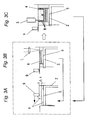
Fig. 2 is a perspective view of an object forming machine pertaining to the present invention; -
Figs. 3A to 3C are explanatory diagrams showing a process ranging from supply of a powdery material to high speed machining in the object making method of according to the first embodiment of the present invention, respectively; -
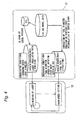
Fig. 4 is an explanatory diagram showing a process ranging from data generation to trimming through sintering in the object making method according to the first embodiment of the present invention; -
Figs. 5A and 5B are explanatory diagram showing a modification of the first embodiment of the present invention; -
Fig. 6 is an explanatory diagram showing the modification ofFigs. 5A and 5B in a simplified fashion; -
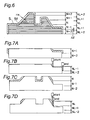
Figs. 7A to 7D are explanatory diagrams showing the modification ofFigs. 5A and 5B , shown in sequence of process steps, respectively; -
Figs. 8A and 8B are explanatory diagrams showing another modification of the first embodiment of the present invention, respectively; -
Figs. 9A and 9B are explanatory diagrams showing a further modification of the first embodiment of the present invention, respectively; -
Figs. 10A to 10C are explanatory diagrams showing a still further modification of the first embodiment of the present invention, respectively; -
Figs. 11A and 11B are explanatory diagrams showing a yet further modification of the second embodiment of the present invention, respectively; -
Fig. 12 is an explanatory diagram used to explain the modification shown inFigs. 11A and 11B ; -
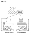
Fig. 13 is a conceptual diagram showing respective data on a trimming path and the path of travel of a sintering beam that are created from profile data of a three-dimensional model; -
Fig. 14 is a conceptual diagram showing a relation between the respective data on the trimming path and the path of travel of the sintering beam; -
Fig. 15 is an explanatory diagram showing the object making method according to a second preferred embodiment of the present invention; -
Fig. 16 is an explanatory diagram showing a modification of the second embodiment of the present invention; -
Figs. 17A and 17B are explanatory diagrams showing another modification of the second embodiment of the present invention, respectively; -
Figs. 18A and 18B are explanatory diagrams showing a further modification of the second embodiment of the present invention, respectively; -
Figs. 19A and 19B are conceptual diagrams showing a zone to be removed and a zone to be left untrimmed in the practice of the modified object making method shown above, respectively; -
Figs. 20A to 20D are explanatory diagrams showing the prior art object making method, respectively; -
Figs. 21A to 21C are different explanatory diagrams showing the prior art object making method, respectively; and -
Fig. 22 is an explanatory diagram conceptually showing a relationship in dimension between a contour of a laminated body and a contour of a cross-sectional shape of one of the laminated bodies that is finally finished. - Various preferred embodiments of the present invention will now be described with reference to the accompanying drawings.
-
Figs. 1A to 1D illustrate a conception of a process of removing, with amachining tool 3, an excessively sintered growth M1 formed as a result of application of laser energy to form a sintered layer, which forms the lowermost one of a plurality of sintered layers of a laminated body Mb, immediately above the uppermost one of a plurality of sintered layers of the underlying laminated body Ma. As is well known to those skilled in the art, an integral three-dimensional object can be obtained by forming a desired or required number of individually contoured sintered layers of the same or gradually varying shape on a support base. However, the physical limitation inherent in and/or imposed on themachining tool 3 does not allow unwanted portions to be removed from around the entire number of the sintered layers all at a time and, accordingly, removal of those unwanted portions of the sintered layers is generally practiced for each of the laminated bodies each consisting a predetermined number of, for example, 60 sintered layers. So far shown inFigs. 1A and 1B , the three-dimensional object desired to be produced is assumed to be a solid cylinder made up of two laminated bodies Ma and Mb each consisting of, for example, 60 sintered layers. -
Fig. 2 schematically illustrates an object forming apparatus including atrimming mechanism 8 including themachining tool 3 such as, for example, a ball end mill, an optical beam projector 7, abeam deflector 8, and aleveling blade 9 for leveling a top surface of a layer of organic or inorganic powdery material dispensed over a target surface which may be a support base or one or more sintered layers deposited on the support base. The object forming apparatus so far shown inFig. 2 may be of any known construction and, briefly speaking, operates to performs sequential processes of supplying a quantity of the powdery material over thesupport base 5 mounted atop an elevating table 2 to form apowdery layer 4 that is subsequently leveled by the leveling blade 9 (Fig. 3A ); irradiating, with a sintering beam L such as a laser beam, the leveled layer of the powdery material so as to scan and sinter at least a portion of the leveled layer of the powdery material substantially in a raster scan fashion to thereby form a sintered layer of a cross-sectional configuration generally matching with that of a corresponding portion of an eventually formed object (Fig. 3B ); and, after a cycle of the dispensing and irradiating processes have been performed in a number of times, corresponding to the number of the sintered layers in one laminated body, to form the respective sintered layers to thereby form that single laminated body M with the adjoining sintered layers having been interlocked with each other, removing unwanted portions of the sintered layers from around the entire number to thereby render the respective sintered layers to have a cross-sectional configuration substantially matching with the corresponding cross-sectional configurations of the object (Fig. 3C ). Where the laminated body is desired to be formed in a plural number, that is, where the object desired or required to be formed is made up of a plurality of the laminated bodies, a cycle of these successive processes discussed above may be repeated a number of times corresponding to the number of the laminated bodies so desired or required. -
Fig. 4 illustrates an object forming system made up of a CAD (computer aided design)data generating unit 11 and an object forming station 12 linked with the CADdata generating unit 11. - Referring now to
Figs. 3A to 3C , and particularly toFigs. 2 and3A , a quantity of organic or inorganicpowdery material 4 is dispensed over thebase 5 resting atop the elevating table 2, which is then leveled by a traversal of theleveling blade 9 to render thepowdery layer 4 to have a predetermined thickness Δt. Subsequently, as shown inFig. 3B the optical beam L from the optical beam projector 7 is directed towards thepowdery layer 4 through thebeam deflector 8 so as to impinge upon at least that portion of the leveledpowdery layer 4 which, when the directed optical beam L scan thepowdery layer 4 substantially in a raster scan fashion, form a sintered layer of a cross-sectional configuration generally matching with that of a corresponding portion of an eventually formed object. This cycle of dispensing the powdery material, leveling the dispensed powdery material and sintering the leveled powdery material to form a single sintered layer is repeated a number of times corresponding to the number of the sintered layers desired or required to form a single laminated body M. The elevating table 2 with thebase 5 mounted thereon is lowered stepwise each time a single sintered layer is formed to allow the underlying sintered layer to accommodate another quantity of the powdery material that is dispensed to eventually form the next succeeding sintered layer.Fig. 3C illustrates the condition in which the above discussed cycles has been performed eight times to form a stack of eight laminated bodies M firmly fusion bonded together. - It is, however, to be noted that considering the single sintered layer having a fairly small thickness, say, about 0.05 mm, the object desired to be formed may require a stack of a plurality of
laminated bodies 4. By way of example, if the object desired to be formed has a height of about 10 cm, the number of the sintered layers to be formed would amounts to about 2000 which would define about 34 laminated bodies M if each laminated body M consists of about 60 sintered layers. -
Fig. 3C also illustrates the condition in which, in order to complete the object of a configuration made up of a cylindrical wall and a bottom wall with a protrusion formed on an inner surface of the bottom wall, the object resting on thebase 5 is subjected to the trimming process. This trimming process is performed to remove not only the unwanted portions of the sintered layers from around the entire number, but also the excessively sintered growth M1 formed as a result of application of laser energy to form a sintered layer, which forms the lowermost one of a plurality of sintered layers of the laminated body Mb, immediately above the uppermost one of a plurality of sintered layers of the underlying laminated body Ma as discussed with reference toFig. 1C . In accordance with the present invention, this trimming process is performed in a manner as will be described in detail later, each time a single laminated body M is formed to remove not only the unwanted portions of the laminated body M from therearound, but a relatively fragile outer surface area of each laminated body M that contains a low density of particles of the powdery material. - In the practice of the present invention, the powdery material that can be employed may be a mass of globular iron particles having an average particle size of about 20 µm, with each sintered layer being about 0.05 mm in thickness, and the optical sintering beam L may be a CO2 laser. The
leveling blade 9 is supported for movement in a plane parallel to the target surface that is scanned by the optical sintering beam L. If themachining tool 3 in the form of a ball end mill of 1 mm in diameter and having an effective blade length of 5 mm is used to trim a depth of 3 mm during the trimming process, a single pass of trimming would be sufficient to remove unwanted portions from around the laminated body M consisting of 60 sintered layers (i.e., = (Machining Depth)/(Thickness of Each Sintered Layer)). Themachining tool 3 is drivingly associated with an X-Y table such that themachining tool 3 can be relatively moved horizontally when the X-Y table is moved in a plane defined by a Cartesian coordinate system and can also be moved relatively vertically, i.e., in a Z-axis direction when the elevating table 2 is moved vertically in a direction perpendicular to the plane in which it moves horizontally. - It is to be noted that other than grinding by the use of the ball end mill referred to above, the trimming process may be performed by grinding with the use of a flat end mill, polishing or blasting. Also, the trimming process can may be accomplished by the use of a thermal means such as heating by irradiation of a laser beam or by the use of any other chemical technique such as a chemical polishing.
- The path of travel of the optical sintering beam L and the trace of travel of the
machining tool 3 are programmed in the form of a 3D CAD data with a suitable 3D CAD software in the CADdata generating unit 11. Specifically, the path of travel of the optical sintering beam L utilizes a contour data descriptive of a cross-sectional configuration of slices obtained by cutting a 3D CAD model, represented by the 3D CAD data, at the pitch of for example, 0.05 mm. On the other hand, the object forming unit 12 adopts a contour machining technique and generates data on the path of travel of the sintering laser and trimming path data using the same 3D CAD model discussed above. It is to be noted that the pitch in the vertical direction, that is, the Z-axis direction of the contour machining path may not be always limited to the direction in which the sintered layers are laminated and that where a gentle slope exists, interpolation may be effected that the pitch in the Z-axis direction may be so small as to enable the entire surface of the eventually obtained object to be ground. - Hereinafter, the sintering process and the trimming process will be discussed. As discussed above, the optical sintering beam L is directed towards a layer of
powdery material 4 dispensed over thesupport base 5, which may form a part of the eventually formed object, so as to irradiate at least that portion of the layer of the powdery material to form a sintered layer as shown inFig. 1A . This sintering is repeatedly performed until a single laminated block Ma consisting of a predetermined number of, for example, 60 sintered layers is formed as shown inFig. 1B . Referring still toFig. 1B , after the formation of the single laminated body M, an outer peripheral surface area of the laminated body Ma and unwanted portions thereof are removed by themachining tool 3 to thereby complete the first laminated body Ma. This formation of the single laminated body Ma may be similar to that practiced by the known object forming method. - Then, as shown in
Fig. 1C , an overlaying laminated body Mb similar in structure to the underlying laminated body Ma is formed on the underlying laminated body Ma by repeating the process used to form the underlying laminated body Ma with reference toFigs. 1A and 1B . However, a process different from that used for trimming the outer peripheral surface area of the first laminated body Ma is employed for trimming an outer peripheral surface area of the second laminated body Mb. Specifically, when the overlaying laminated body Mb is to be trimmed to remove the outer peripheral surface area thereof, a trimming zone A in which themachining tool 3 works on the outer peripheral surface area of the overlaying laminated body Mb is so defined as to encompass the size of the growth M1 protruding downwardly beyond a sintered zone B corresponding to the thickness of the overlaying laminated body Mb. As discussed hereinbefore, the growth M1 is formed as a result of application of laser energy to form a sintered layer, which forms the lowermost sintered layer of the overlaying laminated body Mb, immediately above the uppermost sintered layer of the underlying laminated body Ma. Specifically, the trimming path data U is created in anticipation of formation of the growth M1 formed from an excessive powdery material sintered around the underlying laminated body Ma which has already been trimmed so that themachining tool 3 can start trimming in the trimming zone A so defined to remove not only the outer peripheral surface area of the overlaying laminated body Mb, but also the growth M1. - With the trimming zone A so defined ad discussed above, the
machining tool 3 can be set in position to start trimming not only the outer peripheral surface area of the overlaying laminated body Mb, but also the growth M1 as shown inFig. 1D . Accordingly, the growth M1 resulting from sintering of that excessive powdery material which is, according to the prior art, left unremoved, but is machined after completion of the object, can be removed and, therefore, theobject 1 so formed can have a smooth surface enough to alleviate the use of a post machining process that is otherwise subjected after the object has been completely formed. - As discussed above, in the embodiment shown in
Figs. 1A to 1D , the height AH of the trimming zone A is chosen to be greater than the height BH of the sintered zone B, i.e., the thickness of the overlaying laminated body Mb with the lowermost limit A1 of the trimming zone A set to a position downwardly of the lowermost limit B1 of the sintered zone B, that is, a level flush with a bottom surface of the overlaying laminated body Mb, so that the excessively sintered growth M1 can be encompassed within a margin a bound between the lowermost limits A1 and B1 of the trimming and sintered zones A and B, to thereby ensure that the excessively sintered growth M1 can be removed during the trimming process. - However, as a modification shown in
Figs. 5A and 5B , the trimming zone A may have a height AH that is equal to the height BH of the sintered zone B, but is defined displaced downwardly from the sintered zone B so that the growth M1 can be encompassed within the trimming zone A at a location above the lowermost limit A1 thereof. It is to be noted that while each of the underlying and overlaying laminated bodies Ma and Mb is shown having an outer peripheral surface tapering upwardly as indicated by C, it may have a cylindrical outer peripheral surface as shown in D inFigs. 1A to 1D . - According to the embodiment shown in
Figs. 5A and 5B , the trimming path is so defined as to start the trimming process from a level generally intermediate of the height of the sintered zone B and then to proceeds to a level below the lowermost limit B1 of the sintered zone B. Accordingly, the excessively sintered growth M1 can be removed satisfactorily. In addition, since as clearly shown inFig. 5B , an upper portion B3 of the sintered zone B of the overlying laminated body Mb is left unremoved, the presence of that upper portion B3 makes it difficult for a similar excessively sintered growth to be formed during subsequent formation of a third formed laminated body (not shown ) overlying the laminated body Mb and, accordingly, the size of the subsequently formed growth M1 can be reduced. As a matter of course, an outer peripheral surface area of the upper portion B3 of the second laminated body Mb may be trimmed after a third formed laminated body has been formed above the second laminated body Mb. - Referring now to
Fig. 6 , a sintered object shown therein is made up of a plurality of laminated bodies each consisting of a plurality of sintered layers and, for the trimming process, a plurality of trimming blocks are defined, with each trimming block having a heightwise range different from that of the corresponding laminated body. - In the example shown in
Fig. 6 , after formation of the laminated body N-1 as shown inFig. 7A , the trimming process is applied to a NL-1 block defined below the laminated body N-1 as shown inFig. 7B and, after formation of the laminated body N above the laminated body N-1 as shown inFig. 7C , the trimming process is applied to the next adjacent NL block defined below the laminated body N. as shown inFig. 7D . - The difference in level between each laminated body and the corresponding trimming block, indicated by ΔZ, that is, the lowering increment over which the
machining tool 3 is lowered is preferably set to a value greater than the thickness Hz of that outer surface area to be removed. By way of example, if Hz = 0.2, the difference ΔZ is preferably within the range of 0.25 to 0.30 mm. This choice is effective to avoid a problem associated with the optical sintering beam being undesirably redirected to a finished surface of the object from which the unwanted surface area has been removed. - In the embodiments shown in
Figs. 5A and 5B , respectively, in creating the machining data, a plane of separation W between the sintered zone B and the trimming zone A has been set to extend horizontally and parallel to thesupport base 5. However, the present invention may not be always limited thereto and the plane of separation W may be inclined as shown inFigs. 8A and 8B . -
Figs. 9A and 9B illustrate a modified form of the example shown in and described with reference toFigs. 5A and 5B . In these figures, the uppermost limit A2 of the trimming zone A is positioned above the uppermost limit B2 of the sintered zone B and the lowermost limit A1 of the trimming zone A is positioned below the lowermost limit B1 of the sintered zone B, so as to encompass the excessively sintered growth M1, whereby the height BH of the sintered zone B is smaller than the height AH of the trimming zone A. - According to the example shown in
Figs. 9A and 9B , since the trimming zone A encompasses the excessively sintered growth M1 above the lowermost limit A1 of the trimming zone A, as is the case with that shown in and described with reference toFigs. 5A and 5B , the excessively sintered growth M1 can be removed assuredly at the end of trimming. Also, since the uppermost limit A2 of the trimming zone A is defined at a level above the uppermost limit B2 of the sintered zone B, at the beginning of cutting performed from above, themachining tool 3 may rotate idle because of the absence of the laminated body, but as the trimming proceeds, themachining tool 3 can remove the excessively sintered growth M1. Accordingly, at the beginning of trimming an abrupt cutting resistance will not act on themachining tool 3, thereby minimizing damage to themachining tool 3. -
Figs. 10A to 10C illustrate an example in which the trimming process is performed while only a predetermined thickness of an upper portion B3' of the sintered zone B defining the underlying laminated body Ma is left unremoved. Although the example shown inFigs. 10A to 10C is basically similar to that shown in and described with reference toFigs. 5A and 5B , this example is not limited to the height BH of the sintered zone B being equal to the height AH of the trimming zone A. - Specifically, after an outer surface area of a lower portion of the underlying laminated body Ma other than an upper portion B3' thereof has been removed and the overlaying laminated body Mb has subsequently been formed as shown in
Fig. 10A , an outer surface area of a lower portion of the overlying laminated body Mb other than an upper portion B3 thereof is removed by the trimming process as shown inFig. 10B . Then, as shown inFig. 10C , a third laminated body Mc is formed above and on the second laminated body Mb. According to the example shown inFigs. 10A to 10C , since at the time the second or third laminated body Mb or Mc is formed, the corresponding upper portion B3' or B3 of the second or third laminated body Mb or Mc is left unremoved, the possibility can be substantially eliminated or minimized that an excessively sintered growth would be formed sticking to the trimmed outer surface of the previously laminated body Ma or Mb. Accordingly, a load acting on themachining tool 3 during the trimming process can be lessened and a high efficiency can be appreciated. - It is to be noted that in any one of the foregoing embodiments the trimming zone A has been defined so as to overlap the sintered zone B, but the present invention may not be always limited thereto and at least one sintered zone below or above the sintered zone B occupied by the laminated body M for which the trimming process has finished may be defined as the trimming zone A as shown in
Figs. 11A and 11B . In the example shown inFigs. 11A and 11B , no trimming process is performed to the sintered zone B after sintering to form the laminated body Mb has been finished, but the trimming process is applied to the previously formed laminated body after the next succeeding laminated body has been formed above such previously formed laminated body. For example, trimming may be applied to the laminated body Mb or Ma after the laminated body Mc has been formed on the laminated body Mb. - Thus, according to the embodiment shown in
Figs. 11A and 11B , trimming is effected to the previously formed laminated body that is different from the laminated body having just been formed by sintering and, accordingly, there is no overlap between the laminated zone B and the trimming zone A. This means that there is no possibility that a part of the underlying laminated body and a part of the overlaying laminated body immediately above that part of the underlying laminated body would not be trimmed simultaneously, with efficiency consequently increased. - In another embodiment shown in
Fig. 12 , after the laminated body N+1 has been formed by cyclic repetition of sintering, the trimming zone A of the laminated body N positioned immediately below such laminated body N+1 is subjected to the trimming process. According to this embodiment, since at the time trimming had been effected to the laminated body N, the trimming zone A1 of the overlaying laminated body N+1 is left having not yet been trimmed, sintering of layers of the powdery material successively deposited above the trimming zone A1 can be performed, resulting in reduction in length of time required to calculate a machining data. In such case, however, themachining tool 3 such as a ball end mill is required to have an effective blade length greater than the sum of the respective thickness of the two adjoining laminated bodies. -
Fig. 13 illustrates a method in which when the data on the path of travel of the sintering laser (hereinafter referred to as "beam travel path data") and trimming path data are to be created from 3D profile data of the object desired to be formed, the trimming path data U is at a position (height and width) different from the beam travel path data V so that the excessively sintered growth M1 can be encompassed. - More concretely, as shown in
Fig. 14 , the trimming path data U is so split that it increases downwardly by addition of at least a region Mu encompassing the excessively sintered growth (SeeFigs. 1A to 1D ,Figs. 5A and 5B ,Figs. 8A and 8B, or Figs. 9A and 9B ) than the beam travel path data V. Thus, since a lower region of the trimming path data U includes the region Mu encompassing the excessively sintered growth, the latter can be assuredly removed by trimming. It is to be noted that the width of separation of the path data may not be equal such as shown inFigs. 13 and14 , and separation may be made to a different width depending on the 3D model profile and the machining tool used. - A further embodiment is featured in that as shown in
Fig. 15 , alower surface portion 13 of the outer surface area of the shape of the expected laminated body M, which would be subsequently formed by cyclic repetition of sintering, at a location above the predetermined trimming zone A is defined as an untrimmed area F while the trimming is applied only to a region E exclusive of the untrimmed area F. In other words, thelower surface portion 13 of the outer surface area of the shape of the expected laminated body M, which would be subsequently formed is represented by a portion of the projection formed immediately below the surface area of the shape of the expected laminated body M when the optical sintering beam is directed thereto. Without thelower surface portion 13 being trimmed, and by effecting the trimming only to the region E excluding thelower surface portion 13, successive sintered layers of the laminated body M can be formed above the untrimmed area F. - Specifically, when the predetermined trimming zone A is to be trimmed, the
lower surface portion 13 of the outer surface area of the shape of the laminated body M, which would be subsequently formed above the trimming zone A is left untrimmed, so that when the laminated body M is to be formed by cyclic repetition of sintering, successive sintered layers of the laminated body M above the trimming zone A can be deposited in overlapping relation with thelower surface portion 13 that is defined as the untrimmed portion F. Accordingly, sintering of the powdery material will not be effected at a location where the trimming has been completed will not take place such as occurring in the prior art and, therefore, there is no area that is left untrimmed. - As one method to determine the trimming zone A discussed above, as shown in
Fig. 16 , a portion of the laminated body M immediately above the trimming zone A, which is not included within a target surface area L1 that is to be irradiated with the optical sintering beam may be defined as the region E to be trimmed. In such case, it is possible to define the region E to be trimmed based on the target surface area L1 that is to be irradiated with the optical sintering beam. Also, when trimming pulses are to be generated, they may be so generated that themachining tool 3 will not enter the region F to be left untrimmed. - A modification of the embodiment shown in
Figs. 15 and16 is shown inFigs. 17A and 17B , in which that portion defined as the region F to be left untrimmed during the previous trimming applied to the trimming zone A is determined if it can be trimmed during the subsequent trimming applied to the trimming zone A of the subsequently formed laminated body and, only when it is determined as trimmable, the region F left untrimmed during the previous trimming is added to the region E to be trimmed subsequently. It is to be noted that thearea 30 indicated by the dotted line inFig. 17B represents the area which has already been trimmed. - In this embodiment, as shown in
Fig. 17A , decision is made to determine if that portion defined as the region F to be left unremoved during the trimming of the trimming zone A to which the trimming has already been effected can be trimmed during the subsequently performed trimming applied to the trimming zone A1 of the subsequently formed laminated body. At this time, a portion of the laminated body M1 immediately above the trimming zone A1 that is to be subsequently trimmed, which is not encompassed within the target surface area L1 that is to be irradiated with the optical sintering beam is determined as the region E1 to be trimmed during the subsequent trimming applied to the trimming zone A1, while a portion other than the region E1 is determined as the region F1 to be left untrimmed. In the event that it is determined that the region F left untrimmed during the previous trimming can be trimmed during the subsequent trimming to be effected to remove the region E1, the region F left untrimmed during the previous trimming is removed together with the region E1 being trimmed. - Thus, it will readily be seen that as shown in
Fig. 17A , it is possible to successively form the laminated bodies M and M1 over the region F left untrimmed during the previous trimming. Also, by removing the region F left untrimmed during the previous trimming, which has been determined unnecessary during the subsequent trimming applied to the region E1 to be subsequently trimmed, it is possible to avoid the possibility that the region F determined unnecessary during the previous trimming may be left untrimmed. - Another modification of the embodiment shown in
Figs. 15 and16 is shown inFigs. 18A and 18B , in which comparison is made between the contour S of the laminated body M immediately above a predetermined trimming zone A and cross-sectional contour Sf of an expected laminated body to be subsequently formed or finished, which is at the same height as the contour S of the laminated body M, so that an area outside a region encompassed within the contour S of the laminated body M can be determined as the region E to be trimmed. InFig. 18A , reference character N represents a position at which the trimming is to be effected (for example, a contour path). In this modification, the contour S of the laminated body M immediately thereabove is determined in reference to the pattern L1 of irradiation with the optical sintering beam, followed by comparison of the contour S with the cross-sectional contour Sf of that expected laminated body to be subsequently formed or finished, which is at the same height as the contour S of the laminated body M, so that the area E (Fig. 18B ) outside the region encompassed within the contour S of the laminated body M can be determined as the region E to be trimmed. In this way, it is possible to determine the region E to be trimmed of the predetermined trimming zone A. Also, at the time of generation of the trimming path, it is possible to prevent themachining tool 3 from entering the region F to be left untrimmed. - Where as shown in
Fig. 19A the object desired to be formed has some surface irregularities and/or a generally round end face inside the cross-sectional contour of the object taken in an X-Y plane, an area hatched inFig. 19B is to be defined as the region F to be left untrimmed while the remaining portion is defined as the region E to be trimmed.
Claims (8)
- A method of making a three-dimensional object, which comprises:a) forming an integral laminated body including a plurality of sintered layers of powdery material that are interlocked with each other one above the other, each of said sintered layers being formed by successive processes of dispensing a quantity of the powdery material over a target surface, and directing an optical sintering beam to the dispensed powdery material so as to scan at least a portion of the dispensed powdery material to thereby form the respective sintered layer;b) repeating said successive processes until a predetermined number of the integral laminated bodies are formed; andc) each time the single laminated body is formed, trimming by removing unwanted portions is applied to the lower portion of the outer peripheral surface area of the respective laminated body and sintered protrusion protruding downwardly beyond said laminating body resulting from sintering of excessive powdery material while leaving an upper portion of said overlying laminated body unremoved.
- A method of making a three-dimensional object, which comprises:a) forming an integral laminated body including a plurality of sintered layers of powdery material that are interlocked with each other one above the other, each of said sintered layers being formed by successive processes of dispensing a quantity of the powdery material over a target surface, and directing an optical sintering beam to the dispensed powdery material so as to scan at least a portion of the dispensed powdery material to thereby form the respective sintered layer;b) repeating said successive processes until a predetermined number of the integral laminated bodies are formed; andc) each time the single laminated body is formed, trimming by removing unwanted portions is applied only to the outer peripheral surface area of the previously formed laminated body being different from the laminating body just been formed by sintering.
- The method as claimed in claim 1 or 2, wherein the step c) is initiated from below the laminated body and further below at least a margin of the laminated body that is to be trimmed.
- The method as claimed in claim 1 or 2, wherein when a beam travel path and a trimming path are to be created from a three-dimensional profile data of the object to be formed, data on the trimming path are split at a position different from that of the beam travel path.
- The method as claimed in claim 34, wherein the data on the trimming path are split so as to expand downwardly to encompass an excessively sintered growth that the data on the beam travel path.
- The method as claimed in claim 1 or 2, wherein in the predetermined zone to be removed, a portion of the laminated body immediately there above and that is not encompassed with a pattern of irradiation by the optical sintering beam is determined as a range that can be removed.
- The method as claimed in claim 3, wherein in a split zone to be removed, a decision is made to determine if a portion of the zone to be first removed that is determined as an area to be left untrimmed can be trimmed during trimming of the zone to be removed that is subsequently removed and, only if it is determined that it can be removed, the zone left untrimmed is added to the zone to be removed during the subsequent trimming.
- The method as claimed in claim 1 or 2, wherein comparison is made between a contour of the laminated body immediately above a predetermined trimming zone and cross-sectional contour of an expected laminated body to be subsequently formed, which is at the same height as the contour of the laminated body, so that an area outside a region encompassed with the contour of the laminated body can be determined as the region to be trimmed.
Applications Claiming Priority (4)
| Application Number | Priority Date | Filing Date | Title |
|---|---|---|---|
| JP2002086310 | 2002-03-26 | ||
| JP2002086310 | 2002-03-26 | ||
| JP2002121410A JP3405357B1 (en) | 2002-04-23 | 2002-04-23 | Manufacturing method of metal powder sintered parts |
| JP2002121410 | 2002-04-23 |
Publications (3)
| Publication Number | Publication Date |
|---|---|
| EP1348506A2 EP1348506A2 (en) | 2003-10-01 |
| EP1348506A3 EP1348506A3 (en) | 2005-12-07 |
| EP1348506B1 true EP1348506B1 (en) | 2010-07-28 |
Family
ID=27807015
Family Applications (1)
| Application Number | Title | Priority Date | Filing Date |
|---|---|---|---|
| EP02026502A Expired - Lifetime EP1348506B1 (en) | 2002-03-26 | 2002-11-27 | Method of making sintered object by selective laser sintering |
Country Status (7)
| Country | Link |
|---|---|
| US (1) | US7172724B2 (en) |
| EP (1) | EP1348506B1 (en) |
| KR (1) | KR100499677B1 (en) |
| CN (1) | CN1238140C (en) |
| AT (1) | ATE475502T1 (en) |
| DE (1) | DE60237139D1 (en) |
| TW (1) | TW583042B (en) |
Cited By (2)
| Publication number | Priority date | Publication date | Assignee | Title |
|---|---|---|---|---|
| EP1974688B1 (en) | 2007-03-28 | 2016-01-13 | Institut Straumann AG | Method for manufacturing teeth replacements, method for producing a data record and computer readable medium |
| EP3046702B1 (en) * | 2013-09-20 | 2022-09-28 | Arcam Ab | Method for additive manufacturing of a plurality of three-dimensional articles |
Families Citing this family (27)
| Publication number | Priority date | Publication date | Assignee | Title |
|---|---|---|---|---|
| DE10124795A1 (en) * | 2001-05-21 | 2002-12-12 | Bu St Gmbh Beratungsunternehme | Device and method for producing a workpiece with an exact geometry |
| DE10344902B4 (en) * | 2002-09-30 | 2009-02-26 | Matsushita Electric Works, Ltd., Kadoma | Method for producing a three-dimensional object |
| JP3687677B1 (en) | 2004-10-26 | 2005-08-24 | 松下電工株式会社 | Stereolithography method, stereolithography system, and stereolithography program |
| JP4791745B2 (en) * | 2005-03-28 | 2011-10-12 | パナソニック電工株式会社 | Method of processing light incident / exit part of optical medium |
| TW200815278A (en) | 2006-06-28 | 2008-04-01 | Univ Northwestern | DPN generated hole nanoarrays |
| CN100446897C (en) * | 2006-08-02 | 2008-12-31 | 南昌航空工业学院 | Method for precinct laser sintering fast manufacture metal die |
| WO2009054445A1 (en) * | 2007-10-26 | 2009-04-30 | Panasonic Electric Works Co., Ltd. | Production device and production method of metal powder sintered component |
| DE102008031925B4 (en) * | 2008-07-08 | 2018-01-18 | Bego Medical Gmbh | Dual manufacturing process for small series products |
| DE102008031926A1 (en) | 2008-07-08 | 2010-01-14 | Bego Medical Gmbh | Process for layering steeply inclined surfaces |
| DE102008047118B4 (en) * | 2008-09-15 | 2024-02-01 | Dürr Systems Ag | Painting system component |
| CN102458722B (en) * | 2009-06-23 | 2015-03-18 | 松下电器产业株式会社 | Method for producing three-dimensional formed shapes, and three-dimensional formed shapes obtained thereby |
| JP4566286B1 (en) * | 2010-04-14 | 2010-10-20 | 株式会社松浦機械製作所 | Manufacturing equipment for 3D modeling products |
| US9592554B2 (en) * | 2011-05-23 | 2017-03-14 | Panasonic Intellectual Property Management Co., Ltd. | Method for manufacturing three-dimensional shaped object |
| WO2013167904A1 (en) | 2012-05-10 | 2013-11-14 | Renishaw Plc | Method of manufacturing an article |
| ES2873179T3 (en) | 2012-05-10 | 2021-11-03 | Renishaw Plc | Method of making an item |
| DE102013203936A1 (en) * | 2013-03-07 | 2014-09-11 | Airbus Operations Gmbh | Generative layer building method for producing a three-dimensional object and three-dimensional object |
| DE102013203938A1 (en) * | 2013-03-07 | 2014-09-25 | Airbus Operations Gmbh | Generative layer building method for producing a three-dimensional object and three-dimensional object |
| WO2015039817A1 (en) * | 2013-09-20 | 2015-03-26 | Arcam Ab | Method for additive manufacturing of three-dimensional article(s) |
| TWI535554B (en) * | 2014-01-06 | 2016-06-01 | 財團法人工業技術研究院 | Stereo shaped object and appratus and manufacturing method for stereo shaped object |
| CN104741609B (en) * | 2015-03-31 | 2017-05-03 | 深圳市圆梦精密技术研究院 | Electron beam melting and cutting combined 3D printing equipment |
| EP3127635A1 (en) * | 2015-08-06 | 2017-02-08 | TRUMPF Laser-und Systemtechnik GmbH | Additive manufacturing of down-skin layers |
| DE102015119746A1 (en) * | 2015-11-16 | 2017-05-18 | Cl Schutzrechtsverwaltungs Gmbh | Method for producing a support structure for supporting a generatively traceable three-dimensional object |
| WO2017123995A1 (en) * | 2016-01-14 | 2017-07-20 | Arconic Inc. | Methods for producing forged products and other worked products |
| WO2017124097A1 (en) * | 2016-01-14 | 2017-07-20 | Arccinic Inc. | Methods for producing additively manufactured products |
| US10737326B2 (en) * | 2016-05-19 | 2020-08-11 | Sodick Co., Ltd. | Metal 3D printer |
| GB2557346B (en) * | 2016-12-08 | 2019-01-16 | Betatype Group Ltd | Additive manufacturing |
| JP7213744B2 (en) * | 2019-04-23 | 2023-01-27 | オークマ株式会社 | 3D shape processing method |
Family Cites Families (13)
| Publication number | Priority date | Publication date | Assignee | Title |
|---|---|---|---|---|
| US155384A (en) * | 1874-09-29 | Improvement in | ||
| US62655A (en) * | 1867-03-05 | Moses s | ||
| US5286573A (en) * | 1990-12-03 | 1994-02-15 | Fritz Prinz | Method and support structures for creation of objects by layer deposition |
| US5207371A (en) * | 1991-07-29 | 1993-05-04 | Prinz Fritz B | Method and apparatus for fabrication of three-dimensional metal articles by weld deposition |
| JP3376163B2 (en) | 1995-04-13 | 2003-02-10 | ローランドディー.ジー.株式会社 | Three-dimensional printing apparatus and method |
| DE19533960C2 (en) | 1995-09-13 | 1997-08-28 | Fraunhofer Ges Forschung | Method and device for producing metallic workpieces |
| JP3446618B2 (en) | 1998-08-26 | 2003-09-16 | 松下電工株式会社 | Surface finishing method for metal powder sintered parts |
| DE10065960C5 (en) * | 2000-06-07 | 2005-10-06 | (bu:st) GmbH Beratungsunternehmen für Systeme und Technologien | Method for producing a workpiece with exact geometry |
| US6682688B1 (en) * | 2000-06-16 | 2004-01-27 | Matsushita Electric Works, Ltd. | Method of manufacturing a three-dimensional object |
| JP3446733B2 (en) * | 2000-10-05 | 2003-09-16 | 松下電工株式会社 | Method and apparatus for manufacturing three-dimensional shaped object |
| TW506868B (en) | 2000-10-05 | 2002-10-21 | Matsushita Electric Works Ltd | Method of and apparatus for making a three-dimensional object |
| DE10124795A1 (en) | 2001-05-21 | 2002-12-12 | Bu St Gmbh Beratungsunternehme | Device and method for producing a workpiece with an exact geometry |
| JP3433745B2 (en) * | 2001-11-29 | 2003-08-04 | 松下電工株式会社 | Manufacturing method and manufacturing apparatus for three-dimensional shaped object |
-
2002
- 2002-11-27 US US10/304,963 patent/US7172724B2/en not_active Expired - Lifetime
- 2002-11-27 DE DE60237139T patent/DE60237139D1/en not_active Expired - Lifetime
- 2002-11-27 EP EP02026502A patent/EP1348506B1/en not_active Expired - Lifetime
- 2002-11-27 AT AT02026502T patent/ATE475502T1/en not_active IP Right Cessation
- 2002-11-29 KR KR10-2002-0075286A patent/KR100499677B1/en active IP Right Grant
- 2002-11-29 TW TW091134831A patent/TW583042B/en not_active IP Right Cessation
- 2002-12-02 CN CNB021548293A patent/CN1238140C/en not_active Expired - Lifetime
Cited By (2)
| Publication number | Priority date | Publication date | Assignee | Title |
|---|---|---|---|---|
| EP1974688B1 (en) | 2007-03-28 | 2016-01-13 | Institut Straumann AG | Method for manufacturing teeth replacements, method for producing a data record and computer readable medium |
| EP3046702B1 (en) * | 2013-09-20 | 2022-09-28 | Arcam Ab | Method for additive manufacturing of a plurality of three-dimensional articles |
Also Published As
| Publication number | Publication date |
|---|---|
| EP1348506A3 (en) | 2005-12-07 |
| US7172724B2 (en) | 2007-02-06 |
| TW200304398A (en) | 2003-10-01 |
| CN1446652A (en) | 2003-10-08 |
| KR20030077933A (en) | 2003-10-04 |
| TW583042B (en) | 2004-04-11 |
| KR100499677B1 (en) | 2005-07-05 |
| CN1238140C (en) | 2006-01-25 |
| EP1348506A2 (en) | 2003-10-01 |
| ATE475502T1 (en) | 2010-08-15 |
| DE60237139D1 (en) | 2010-09-09 |
| US20030185697A1 (en) | 2003-10-02 |
Similar Documents
| Publication | Publication Date | Title |
|---|---|---|
| EP1348506B1 (en) | Method of making sintered object by selective laser sintering | |
| US9550325B2 (en) | Method and apparatus for the production of a workpiece of exact geometry | |
| US6694207B2 (en) | Selective laser sintering with interleaved fill scan | |
| KR100436121B1 (en) | Method of and apparatus for making a three-dimensional object | |
| JP3724437B2 (en) | Manufacturing method and manufacturing apparatus for three-dimensional shaped object | |
| US5398193A (en) | Method of three-dimensional rapid prototyping through controlled layerwise deposition/extraction and apparatus therefor | |
| US7255830B2 (en) | Method of making a three-dimensional sintered product | |
| US6657155B2 (en) | Method of and apparatus for making a three-dimensional object | |
| US6677554B2 (en) | Selective laser sintering with optimized raster scan direction | |
| US7754135B2 (en) | Three dimensional structure producing method and producing device | |
| CN101048273B (en) | Photo-shaping method, photo-shaping system, and photo-shaping program | |
| JP6778883B2 (en) | Manufacturing method of 3D shaped object | |
| JP4487636B2 (en) | Manufacturing method of three-dimensional shaped object | |
| JP2004508222A (en) | Procedures for rapid assembly and improved surface properties in laminate manufacturing | |
| JP3803223B2 (en) | Stereolithography method and apparatus for three-dimensional object shaping using recoating parameters for layers | |
| JP6683809B2 (en) | Method and equipment for additionally manufacturing objects | |
| US7941241B2 (en) | Optical fabrication method | |
| JP2002066844A (en) | Method of manufacturing discharge machining electrode using metal powder sintering type laminated molding | |
| JP2004122490A (en) | Method for manufacturing three-dimensionally shaped article | |
| JP3433745B2 (en) | Manufacturing method and manufacturing apparatus for three-dimensional shaped object | |
| JP3405357B1 (en) | Manufacturing method of metal powder sintered parts | |
| CN111790908B (en) | Method for manufacturing layered product, layered product manufacturing apparatus, and layered product | |
| JP3601535B1 (en) | Manufacturing method of three-dimensional shaped object | |
| JP3446756B1 (en) | Surface finishing method for powder sintered parts | |
| CN113732309A (en) | Additive manufacturing method capable of simultaneously improving forming precision and forming efficiency |
Legal Events
| Date | Code | Title | Description |
|---|---|---|---|
| PUAI | Public reference made under article 153(3) epc to a published international application that has entered the european phase |
Free format text: ORIGINAL CODE: 0009012 |
|
| 17P | Request for examination filed |
Effective date: 20021127 |
|
| AK | Designated contracting states |
Kind code of ref document: A2 Designated state(s): AT BE BG CH CY CZ DE DK EE ES FI FR GB GR IE IT LI LU MC NL PT SE SK TR |
|
| AX | Request for extension of the european patent |
Extension state: AL LT LV MK RO SI |
|
| PUAL | Search report despatched |
Free format text: ORIGINAL CODE: 0009013 |
|
| AK | Designated contracting states |
Kind code of ref document: A3 Designated state(s): AT BE BG CH CY CZ DE DK EE ES FI FR GB GR IE IT LI LU MC NL PT SE SK TR |
|
| AX | Request for extension of the european patent |
Extension state: AL LT LV MK RO SI |
|
| RIC1 | Information provided on ipc code assigned before grant |
Ipc: 7B 23K 26/34 B Ipc: 7B 22F 3/105 A Ipc: 7B 29C 67/00 B |
|
| AKX | Designation fees paid |
Designated state(s): AT BE BG CH CY CZ DE DK EE ES FI FR GB GR IE IT LI LU MC NL PT SE SK TR |
|
| 17Q | First examination report despatched |
Effective date: 20070301 |
|
| RAP1 | Party data changed (applicant data changed or rights of an application transferred) |
Owner name: PANASONIC ELECTRIC WORKS CO., LTD. |
|
| GRAP | Despatch of communication of intention to grant a patent |
Free format text: ORIGINAL CODE: EPIDOSNIGR1 |
|
| GRAS | Grant fee paid |
Free format text: ORIGINAL CODE: EPIDOSNIGR3 |
|
| GRAA | (expected) grant |
Free format text: ORIGINAL CODE: 0009210 |
|
| RIN1 | Information on inventor provided before grant (corrected) |
Inventor name: TAKENAMI, MASATAKA Inventor name: MACHIDA, SEIZO Inventor name: YOSHIDA, NORIO Inventor name: TOGEYAMA, HIROHIKO Inventor name: HIGASHI, YOSHIKAZU Inventor name: ABE, SATOSHI Inventor name: FUWA, ISAO Inventor name: UENAGA, SHUSHI |
|
| RAP1 | Party data changed (applicant data changed or rights of an application transferred) |
Owner name: PANASONIC ELECTRIC WORKS CO., LTD. |
|
| AK | Designated contracting states |
Kind code of ref document: B1 Designated state(s): AT BE BG CH CY CZ DE DK EE ES FI FR GB GR IE IT LI LU MC NL PT SE SK TR |
|
| REG | Reference to a national code |
Ref country code: GB Ref legal event code: FG4D |
|
| REG | Reference to a national code |
Ref country code: CH Ref legal event code: EP |
|
| REG | Reference to a national code |
Ref country code: IE Ref legal event code: FG4D |
|
| REF | Corresponds to: |
Ref document number: 60237139 Country of ref document: DE Date of ref document: 20100909 Kind code of ref document: P |
|
| REG | Reference to a national code |
Ref country code: NL Ref legal event code: VDEP Effective date: 20100728 |
|
| PG25 | Lapsed in a contracting state [announced via postgrant information from national office to epo] |
Ref country code: FI Free format text: LAPSE BECAUSE OF FAILURE TO SUBMIT A TRANSLATION OF THE DESCRIPTION OR TO PAY THE FEE WITHIN THE PRESCRIBED TIME-LIMIT Effective date: 20100728 Ref country code: NL Free format text: LAPSE BECAUSE OF FAILURE TO SUBMIT A TRANSLATION OF THE DESCRIPTION OR TO PAY THE FEE WITHIN THE PRESCRIBED TIME-LIMIT Effective date: 20100728 Ref country code: AT Free format text: LAPSE BECAUSE OF FAILURE TO SUBMIT A TRANSLATION OF THE DESCRIPTION OR TO PAY THE FEE WITHIN THE PRESCRIBED TIME-LIMIT Effective date: 20100728 |
|
| PG25 | Lapsed in a contracting state [announced via postgrant information from national office to epo] |
Ref country code: BG Free format text: LAPSE BECAUSE OF FAILURE TO SUBMIT A TRANSLATION OF THE DESCRIPTION OR TO PAY THE FEE WITHIN THE PRESCRIBED TIME-LIMIT Effective date: 20101028 Ref country code: CY Free format text: LAPSE BECAUSE OF FAILURE TO SUBMIT A TRANSLATION OF THE DESCRIPTION OR TO PAY THE FEE WITHIN THE PRESCRIBED TIME-LIMIT Effective date: 20100728 Ref country code: PT Free format text: LAPSE BECAUSE OF FAILURE TO SUBMIT A TRANSLATION OF THE DESCRIPTION OR TO PAY THE FEE WITHIN THE PRESCRIBED TIME-LIMIT Effective date: 20101129 |
|
| PG25 | Lapsed in a contracting state [announced via postgrant information from national office to epo] |
Ref country code: SE Free format text: LAPSE BECAUSE OF FAILURE TO SUBMIT A TRANSLATION OF THE DESCRIPTION OR TO PAY THE FEE WITHIN THE PRESCRIBED TIME-LIMIT Effective date: 20100728 Ref country code: GR Free format text: LAPSE BECAUSE OF FAILURE TO SUBMIT A TRANSLATION OF THE DESCRIPTION OR TO PAY THE FEE WITHIN THE PRESCRIBED TIME-LIMIT Effective date: 20101029 Ref country code: BE Free format text: LAPSE BECAUSE OF FAILURE TO SUBMIT A TRANSLATION OF THE DESCRIPTION OR TO PAY THE FEE WITHIN THE PRESCRIBED TIME-LIMIT Effective date: 20100728 |
|
| PG25 | Lapsed in a contracting state [announced via postgrant information from national office to epo] |
Ref country code: DK Free format text: LAPSE BECAUSE OF FAILURE TO SUBMIT A TRANSLATION OF THE DESCRIPTION OR TO PAY THE FEE WITHIN THE PRESCRIBED TIME-LIMIT Effective date: 20100728 |
|
| PG25 | Lapsed in a contracting state [announced via postgrant information from national office to epo] |
Ref country code: SK Free format text: LAPSE BECAUSE OF FAILURE TO SUBMIT A TRANSLATION OF THE DESCRIPTION OR TO PAY THE FEE WITHIN THE PRESCRIBED TIME-LIMIT Effective date: 20100728 Ref country code: IT Free format text: LAPSE BECAUSE OF FAILURE TO SUBMIT A TRANSLATION OF THE DESCRIPTION OR TO PAY THE FEE WITHIN THE PRESCRIBED TIME-LIMIT Effective date: 20100728 Ref country code: CZ Free format text: LAPSE BECAUSE OF FAILURE TO SUBMIT A TRANSLATION OF THE DESCRIPTION OR TO PAY THE FEE WITHIN THE PRESCRIBED TIME-LIMIT Effective date: 20100728 Ref country code: EE Free format text: LAPSE BECAUSE OF FAILURE TO SUBMIT A TRANSLATION OF THE DESCRIPTION OR TO PAY THE FEE WITHIN THE PRESCRIBED TIME-LIMIT Effective date: 20100728 |
|
| PLBE | No opposition filed within time limit |
Free format text: ORIGINAL CODE: 0009261 |
|
| STAA | Information on the status of an ep patent application or granted ep patent |
Free format text: STATUS: NO OPPOSITION FILED WITHIN TIME LIMIT |
|
| PG25 | Lapsed in a contracting state [announced via postgrant information from national office to epo] |
Ref country code: MC Free format text: LAPSE BECAUSE OF NON-PAYMENT OF DUE FEES Effective date: 20101130 Ref country code: ES Free format text: LAPSE BECAUSE OF FAILURE TO SUBMIT A TRANSLATION OF THE DESCRIPTION OR TO PAY THE FEE WITHIN THE PRESCRIBED TIME-LIMIT Effective date: 20101108 |
|
| REG | Reference to a national code |
Ref country code: CH Ref legal event code: PL |
|
| 26N | No opposition filed |
Effective date: 20110429 |
|
| GBPC | Gb: european patent ceased through non-payment of renewal fee |
Effective date: 20101127 |
|
| PG25 | Lapsed in a contracting state [announced via postgrant information from national office to epo] |
Ref country code: LI Free format text: LAPSE BECAUSE OF NON-PAYMENT OF DUE FEES Effective date: 20101130 Ref country code: CH Free format text: LAPSE BECAUSE OF NON-PAYMENT OF DUE FEES Effective date: 20101130 |
|
| REG | Reference to a national code |
Ref country code: FR Ref legal event code: ST Effective date: 20110801 |
|
| REG | Reference to a national code |
Ref country code: DE Ref legal event code: R097 Ref document number: 60237139 Country of ref document: DE Effective date: 20110429 |
|
| PG25 | Lapsed in a contracting state [announced via postgrant information from national office to epo] |
Ref country code: FR Free format text: LAPSE BECAUSE OF NON-PAYMENT OF DUE FEES Effective date: 20101130 Ref country code: IE Free format text: LAPSE BECAUSE OF NON-PAYMENT OF DUE FEES Effective date: 20101127 |
|
| PG25 | Lapsed in a contracting state [announced via postgrant information from national office to epo] |
Ref country code: GB Free format text: LAPSE BECAUSE OF NON-PAYMENT OF DUE FEES Effective date: 20101127 |
|
| PG25 | Lapsed in a contracting state [announced via postgrant information from national office to epo] |
Ref country code: LU Free format text: LAPSE BECAUSE OF NON-PAYMENT OF DUE FEES Effective date: 20101127 |
|
| PG25 | Lapsed in a contracting state [announced via postgrant information from national office to epo] |
Ref country code: TR Free format text: LAPSE BECAUSE OF FAILURE TO SUBMIT A TRANSLATION OF THE DESCRIPTION OR TO PAY THE FEE WITHIN THE PRESCRIBED TIME-LIMIT Effective date: 20100728 |
|
| PGFP | Annual fee paid to national office [announced via postgrant information from national office to epo] |
Ref country code: DE Payment date: 20211005 Year of fee payment: 20 |
|
| REG | Reference to a national code |
Ref country code: DE Ref legal event code: R071 Ref document number: 60237139 Country of ref document: DE |