EP1347058A2 - Electrochemical biosensor with connector windows - Google Patents
Electrochemical biosensor with connector windows Download PDFInfo
- Publication number
- EP1347058A2 EP1347058A2 EP03006031A EP03006031A EP1347058A2 EP 1347058 A2 EP1347058 A2 EP 1347058A2 EP 03006031 A EP03006031 A EP 03006031A EP 03006031 A EP03006031 A EP 03006031A EP 1347058 A2 EP1347058 A2 EP 1347058A2
- Authority
- EP
- European Patent Office
- Prior art keywords
- support substrate
- biosensor
- electrodes
- electrode
- sensor support
- Prior art date
- Legal status (The legal status is an assumption and is not a legal conclusion. Google has not performed a legal analysis and makes no representation as to the accuracy of the status listed.)
- Withdrawn
Links
Images


Classifications
-
- G—PHYSICS
- G01—MEASURING; TESTING
- G01N—INVESTIGATING OR ANALYSING MATERIALS BY DETERMINING THEIR CHEMICAL OR PHYSICAL PROPERTIES
- G01N27/00—Investigating or analysing materials by the use of electric, electrochemical, or magnetic means
- G01N27/26—Investigating or analysing materials by the use of electric, electrochemical, or magnetic means by investigating electrochemical variables; by using electrolysis or electrophoresis
- G01N27/28—Electrolytic cell components
- G01N27/30—Electrodes, e.g. test electrodes; Half-cells
- G01N27/327—Biochemical electrodes, e.g. electrical or mechanical details for in vitro measurements
- G01N27/3271—Amperometric enzyme electrodes for analytes in body fluids, e.g. glucose in blood
- G01N27/3272—Test elements therefor, i.e. disposable laminated substrates with electrodes, reagent and channels
Definitions
- the present invention is directed to a biosensor and a method of forming same. More particularly, the present invention is directed to a biosensor with connector windows that expose electrode contacts for engagement with a meter.
- Electrochemical biosensors are known. They have been used to determine the concentration of various analytes from biological samples, particularly from blood. Electrochemical biosensors are described in U.S. Patent Nos. 5,413,690; 5,762,770; 5,798,031; and 5,997,817 the disclosure of each of which is expressly incorporated herein by reference.
- a biosensor comprising an electrode support substrate, electrodes positioned on the electrode support, each electrode including a meter-contact portion and a measurement portion, and a sensor support substrate.
- the sensor support substrate cooperates with the electrode support substrate to define a channel in alignment with the measurement portion of the electrodes.
- the sensor support substrate includes opposite ends and at least one window. The at least one window is spaced-apart from the ends and in alignment with the meter-contact portion of at least one of the electrodes.
- a method of forming a biosensor comprises the steps of forming electrodes on a surface of an electrode support substrate, each electrode including a meter-contact portion and a measurement portion, forming a sensor support substrate having opposite ends and at least one window spaced apart from the opposite ends, coupling the sensor support and the electrode support substrate together so that the at least one window is aligned with the meter-contact portion of the electrodes, and applying a reagent to the measurement portion of the electrodes.
- a biosensor in accordance with another aspect of the invention, comprises an electrode support substrate, electrodes positioned on the electrode support substrate, each electrode including a meter-contact portion and a measurement portion, a sensor support substrate coupled to the electrode support substrate, the sensor support substrate including opposite ends, an opening in alignment with the measurement portion of the electrodes and at least one window spaced-apart from the ends and in alignment with the meter-contact portion of the electrodes, and a cover coupled to the sensor support substrate.
- the present invention relates to a biosensor and method of manufacturing said biosensor.
- This biosensor of the present invention includes opposite ends and is beneficially formed to enable a user to grasp ends without touching electrode contacts, which are themselves formed to electrically connect with a meter.
- Biosensors of the present invention include at least one discrete window spaced-apart from the end of the biosensor.
- the at least one window serves as a built-in fiducial for alignment of the biosensor, enabling easy automated process control during assembly.
- the at least one discrete window is a significant advantage for an integrated strip handling system, since each window creates a detent, providing mechanical feedback for strip mating with meter contacts.
- strip alignment problems are eliminated enabling multiple strip configurations to be used with a single meter. That is, the discrete windows of the biosensor prevent problems associated with closely spaced electrode pads touching the wrong meter contact. Aspects of the invention are presented in Figs. 1-15, which are not drawn to scale and wherein like components in the several views are numbered alike.
- a biosensor 10 is shown in Figs. 1-4.
- the term analyte refers to the molecule or compound to be quantitatively determined.
- Non-limiting examples of analytes include carbohydrates, proteins, such as hormones and other secreted proteins, enzymes, and cell surface proteins; glycoproteins; peptides; small molecules; polysaccharides; antibodies (including monoclonal or polyclonal Ab); nucleic acids; drugs; toxins; viruses of virus particles; portions of a cell wall; and other compounds processing epitopes.
- the analyte of interest preferably comprises glucose.
- Biosensor 10 is shown in Fig. 1 and includes opposite ends 11, 13, either of which is available to be grasped by a user without contact with electrodes of the biosensor 10. As shown in Fig. 2A, the biosensor 10 includes an electrode support substrate 12 and an electrical conductor 14 positioned on the substrate 12. The conductor 14 is disrupted to define electrodes 16, 18, 20. Biosensor 10 also includes a sensor support substrate 22 positioned on the substrate 12 and a cover substrate 24 positioned on the sensor support substrate 22. Biosensor 10 is in the form of a disposable test strip. It is appreciated however, that biosensor 10 can assume any number of forms and shapes in accordance with this disclosure.
- Biosensor 10 is preferably produced from rolls of material. It is understood that biosensor 10 also can be constructed from individual sheets in accordance with this disclosure. When biosensors 10 are produced from rolls, the selection of materials necessitates the use of materials that are sufficiently flexible for roll processing, but which are still rigid enough to give a useful stiffness to finished biosensor 10.
- the electrode support substrate 12 includes a first surface 26 facing the sensor support substrate 22 and a second surface 28.
- substrate 12 has opposite first and second ends 30, 32 and opposite edges 34, 36 extending between the first and second ends 30, 32.
- Edge 34 of substrate 12 is formed to include a generally concave-shaped notch 38. It is appreciated that substrate 12 may be formed without a notch, or that the notch may take on any number of shapes and sizes in accordance with the present disclosure.
- Electrode support substrate 12 is generally rectangular in shape, it is appreciated however, that support 12 may be formed in a variety of shapes and sizes in accordance with this disclosure. It is also appreciated that the substrate 12 need not necessarily extend the length of the substrate 22 as shown in Figs. 1 and 2A. In fact, the substrate 12 can have a shorter length so long as it is of sufficient length to position the electrodes with a channel and windows as will be described hereafter.
- Substrate 12 may be constructed from a wide variety of insulative materials. Non-limiting examples of insulative materials that provide desirable electrical and structural properties include glass, ceramics, vinyl polymers, polyimides, polyesters, and styrenics.
- substrate 12 is a flexible polymer, such as a polyester or polyimide.
- a non-limiting example of a suitable material is 5 mil (125 um) thick KALADEX®, a polyethylene naphthalate film commercially available from E.I. DuPont de Nemours, Wilmington, Delaware, which is coated with gold by ROWO Coating, Henbolzhelm, Germany. It is appreciated that the thickness of the support 12 can be greater or less than 5 mil (125 um) and may be suitable for a number of assembly processes (e.g., lamination, etc.).
- Electrodes 16, 18, 20 are created or isolated from conductor 14 on first surface. 26 of electrode support substrate 12. See Figs. 2A and 3. It is appreciated that electrodes 16, 18, 20 can be formed from multiple layers of same or different electrically conductive materials.
- a suitable electrical conductor 14 include aluminum, carbon (such as graphite), cobalt, copper, gallium, gold, indium, iridium, iron, lead, magnesium, mercury (as an amalgam), nickel, niobium, osmium, palladium, platinum, rhenium, rhodium, selenium, silicon (such as highly doped polycrystalline silicon), silver, tantalum; tin, titanium, tungsten, uranium, vanadium, zinc, zirconium, mixtures thereof, and alloys, oxides, or metallic compounds of these elements.
- electrical conductor 14 is selected from the following materials: gold, platinum, palladium, iridium, or alloys of these metals, since such noble metals and their alloys are unreactive in biological systems. Most preferably, the electrical conductor 14 is gold.
- Electrodes 16, 18, 20 are isolated from the rest of the electrical conductor 14 by laser ablation. Techniques for forming electrodes on a surface using laser ablation are known. See, for example, U.S. Patent Application Serial No. 09/411,940, titled “Laser Defined Features for Patterned Laminates and Electrodes", the disclosure of which is expressly incorporated herein by reference.
- electrodes 16, 18, 20 are created by removing the electrical conductor 14 from an area extending around the electrodes to form a gap 40 of exposed support substrate 12. Therefore, electrodes 16, 18, 20 are isolated from the rest of the electrically-conductive material on substrate 12.
- the gap 40 has a width of about 25 ⁇ m to about 500 ⁇ m, preferably the gap has a width of about 100 ⁇ m to about 200 ⁇ m.
- electrodes 16, 18, 20 may be created by laser ablation alone on substrate 12. It is appreciated that while laser ablation is the preferred method for forming electrodes 16, 18, 20 given its precision and sensitivity, other techniques such as lamination, screen-printing, photolithography, or contact printing may be used in accordance with this disclosure.
- electrodes 16, 18, 20 cooperate with one another to define an electrode array 42.
- electrodes 16, 18, 20 each include a meter-contact portion 44, a measurement portion positioned in the array 42, and a lead 46 extending between the contact 44 and the measurement portion.
- Contacts 44 are spaced apart from end 32. It is appreciated that the contacts 44 can be formed to have many lengths and can extend to end 32 or to edges 34, 36, or to any number of locations on substrate 12.
- the leads 38 that extend from the array 34 can be formed to have many lengths and extend to a variety of locations on the electrode support substrate 12. It is appreciated that the configuration of the electrode array, the number of electrodes, as well as the spacing between the electrodes may vary in accordance with this disclosure and that greater than one array may be formed as will be appreciated by one of skill in the art.
- electrodes 16, 18, 20 are used with a reagent to determine the concentration of at least one analyte in a fluid sample. It is appreciated, however, that at least one of the electrodes may be used for purposes other than a reagent-based measurement.
- electrodes are enabled to be used as an antenna for telemetry, or to signify an expiration date, code number, analyte, etc.). It is also contemplated by the present disclosure to use the electrodes to examine a ratio of currents at one or more time points to determine if the biosensor 10 has been exposed to inappropriate temperature, humidity, interferents, etc.).
- the sensor support substrate 22 of biosensor 10 extends to the end 32 of substrate 12 to permit a user to grasp the end 11 of biosensor 10 without contacting the electrodes 16, 18, 20. It is appreciated, however, that substrate 32 may extend past end 32 in accordance with this disclosure.
- the sensor support substrate 22 is positioned to lie between the electrode support substrate 12 and the cover substrate 24. Referring now to Fig. 4, the sensor support substrate 22 cooperates with the support substrate 12 and the cover 24 to expose the electrode array 42 to a liquid sample (not shown) being applied to the biosensor 10.
- Sensor support substrate 22 can be formed from any number of commercially available insulative materials.
- Non-limiting examples of insulative materials that provide desirable electrical and structural properties include vinyl polymers, polyimides, polyesters, and styrenics.
- the sensor support substrate 22 is 10 mil (250 um) thick opaque white MELINEX® 329 plastic, a polyester commercially available from E.I. DuPont de Nemours, Wilmington, Delaware, which is coated with a thermoplastic resin (Griltex D 1698 E), commercially available from EMS-Chemie (North America) Inc., Sumter, South Carolina.
- sensor support substrate 22 may be formed of a double-sided adhesive tape covered by an insulative material in accordance with the disclosure, so long as it is of a sufficient thickness to create a detent about at least one window 64, as will be described below.
- the sensor support substrate 22 includes a first surface 48 and a second surface 50 facing the electrode support substrate 12.
- a first end 52 of the sensor support substrate 22 is aligned with end 30, a second end 54 is aligned with end 32, an edge 56 is aligned with edge 34, and an opposite edge 58 is aligned with edge 36.
- the edge 56 is formed to include a notch 60 that is shaped so as to be aligned with notch 38 of the substrate 12. It is appreciated that substrate 12 may be formed without a notch, or that the notch may take on any number of shapes and sizes in accordance with the present disclosure.
- An opening 62 extends from the notch 60 toward the edge 58.
- the substrates 12, 22 cooperate to define a channel aligned with the electrodes.
- the measurement portion of the electrodes that cooperate to form the electrode array 42 are positioned to lie in general alignment with the opening 62 and are thus positioned in the channel 78 to expose at least a portion of the electrodes 16, 18, 20 of the electrode array 42.
- An interior border 80 defines the opening 62. The width of the interior border 80 can vary in accordance with this disclosure.
- sensor support substrate 22 extends to the end 32 of substrate 12 and is formed to expose the electrode contacts 44 for engagement with a meter 124.
- a meter A non-limiting example of such a meter is shown diagrammatically in Fig. 10.
- sensor support substrate 22 includes windows 64 that extend between first and second surfaces 48, 50. Each window 64 creates a detent in sensor support substrate 22 and is spaced apart from end 54. This detent provides mechanical feedback for strip mating with meter contacts and increases the rigidity of the substrate 22. Further, the positioning of the windows 64 enables a user to grasp the end 11 of the biosensor 10 without touching the electrode contacts 44. Thus, the inadvertent deposit of skin oils, dirt, skin cells, etc. onto the electrical contacts 44 through simple handling of the biosensor 10 is prevented.
- At least one window 64 may be used to perform alignment of the substrates 12 and 22. It is also appreciated that at least one window 64 may be used to perform alignment for other manufacturing processes such as dispensing, labeling, cutting, punching, etc. Moreover, it is appreciated that windows 64 can take on a variety of shapes and sizes in accordance with the present disclosure. Illustratively, windows 64 are formed to be slightly larger than the respective contacts 44. A non-limiting example of dimensions of suitable windows 64 when contacts have a width of about 1mm and a length of about 2mm, is a width of about 1.5 mm and a length of about 2.5mm. In addition, while three windows 64 are shown, it is appreciated that biosensor 10 can be formed with greater than three windows or as few as one window in accordance with the present disclosure. Non-limiting examples of which include windows illustrated in Figs. 8-10, and 13-15.
- Sensor support substrate 22 is coupled to the electrode support substrate 12 as shown in Fig. 1.
- the thermoplastic resin on surface 48 permits the substrate 22 to be heat-sealed to the conductor 14 coating substrate 12. It is appreciated that substrates 12 and 22 may be coupled together using a wide variety of commercially available adhesives or with welding (heat or ultrasonic on portions of substrate 12 where the conductor 14 has been removed) in accordance with this disclosure. It is also appreciated that first surface 50 of substrate 22 may be printed with, for example, product labeling or instructions for use in accordance with this disclosure.
- the cover substrate 24 is coupled to the spacer support 22 across the opening 62. See Fig. 1.
- the cover substrate 24 of biosensor 10 includes a first surface 66 facing substrate 12, an opposite second surface 68 and a vent 69 extending between surfaces 66, 68.
- cover substrate 24 has opposite first and second ends 70, 72 and edges 74, 76 extending between ends 70, 72.
- Edge 74 is preferably generally concave shape for alignment with notches 38, 60 of substrates 12, 22 respectively. It is appreciated, however, that the edge 74 may take on any number of shapes and sizes in order to be in general alignment with the shape of notches 38, 60.
- the cover substrate 24 is formed of a flexible polymer and preferably from a polymer such as an adhesive coated polyethylene terephthalate (PET) ⁇ polyester.
- PET polyethylene terephthalate
- a non-limiting example of a suitable PET is 2 mil (50 um) thick clear PET film one side of which is coated with a hydrophilic pressure-sensitive adhesive (Product # ARcare 8877) commercially available from Adhesives Research, Inc. Glen Rock, Pennsylvania.
- the cover substrate 24 is formed to cooperate with the sensor support substrate 22 and the support substrate 12 to define a channel 78 extending from edges 34, 56, 74 and across the electrode array 42.
- the channel 78 is preferably a capillary channel that is formed to transport a fluid sample from the user to the electrode array 42. As shown in Fig. 4, the channel 78 extends from edges 34, 56, 74 and is defined by the interior border 80 of the opening 62. It is appreciated that the channel 78 can extend from any number of locations of biosensor 10 to the array 42. It is also appreciated that channel 78 may also be formed from cooperation between only the sensor support substrate 22 and the support substrate 12.
- An electrochemical reagent 82 is positioned on the array 42.
- the reagent 82 provides electrochemical probes for specific analytes.
- the choice of the specific reagent 82 depends on the specific analyte or analytes to be measured, and are well known to those of ordinary skill in the art.
- An example of a reagent that may be used in biosensor 10 of the present invention is a reagent for measuring glucose from a whole blood sample.
- a non-limiting example of a reagent for measurement of glucose in a human blood sample contains 62.2 mg polyethylene oxide (mean molecular weight of 100-900 kilo Daltons), 3.3 mg NATROSOL 244M, 41.5 mg AVICEL RC-591 F, 89.4 mg monobasic potassium phosphate, 157.9 mg dibasic potassium phosphate, 437.3 mg potassium ferricyanide, 46.0 mg sodium succinate, 148.0 mg trehalose, 2.6 mg TRITON X-100 surfactant, and 2,000 to 9,000 units of enzyme activity per gram of reagent.
- the enzyme is prepared as an enzyme solution from 12.5 mg coenzyme PQQ and 1.21 million units of the apoenzyme of quinoprotein glucose dehydrogenase. This reagent is further described in U.S. Patent No. 5,997,817, the disclosure of which is expressly incorporated herein by reference.
- Non-limiting examples of enzymes and mediators that may be used in measuring particular analytes in biosensor 10 are listed below in Table 1.
- At least one additional enzyme is used as a reaction catalyst.
- some of the examples shown in Table 1 may utilize an additional mediator, which facilitates electron transfer to the oxidized form of the mediator.
- the additional mediator may be provided to the reagent in lesser amount than the oxidized form of the mediator.
- a plurality of biosensors 10 are typically packaged in a vial, usually with a stopper formed to seal the vial. It is appreciated, however, that biosensors 10 may be packaged individually, or biosensors can be folded upon one another, rolled in a coil, stacked in a cassette magazine, or packed in blister packaging.
- Biosensor 10 is used in conjunction with the following:
- the meter will normally be adapted to apply an algorithm to the current measurement, whereby an analyte concentration is provided and visually displayed. Improvements in such power source, meter, and biosensor system are the subject of commonly assigned U.S. Pat. No. 4,963,814, issued Oct. 16, 1990; U.S. Pat. No. 4,999,632, issued Mar. 12, 1991; U.S. Pat. No. 4,999,582, issued Mar. 12, 1991; U.S. Pat. No. 5,243,516, issued Sep. 7, 1993; U.S. Pat. No. 5,352,351, issued Oct. 4, 1994; U.S. Pat. No. 5,366,609, issued Nov. 22, 1994; White et al., U.S. Pat. No. 5,405,511, issued Apr. 11, 1995; and White et al., U.S. Pat. No. 5,438,271, issued Aug. 1, 1995, the disclosures of each of which are expressly hereby incorporated by reference.
- fluid samples may be analyzed.
- human body fluids such as whole blood, plasma, sera, lymph, bile, urine, semen, cerebrospinal fluid, spinal fluid, lacrimal fluid and stool specimens as well as other biological fluids readily apparent to one skilled in the art may be measured.
- Fluid preparations of tissues can also be assayed, along with foods, fermentation products and environmental substances, which potentially contain environmental contaminants.
- whole blood is assayed with this invention.
- biosensor 10 is manufactured using six distinct processes.
- a roll of sensor support substrate material 84 is fed into a window punch and web slit station 86.
- the windows 64 and the opening 62 are created through the sensor support substrates in the web and the web is slit to its final dimension in the station.
- the trim, from the edges of the web of material is removed from the material and wound into a roll 88.
- the punched sensor support substrates connected to one another via a web are wound into a roll 90.
- a roll of metallized electrode support material 92 is fed into an ablation/washing and drying station 94.
- a laser system capable of ablating support 12 is known to those of ordinary skill in the art. Non-limiting examples of which include excimer lasers, with the pattern of ablation controlled by mirrors, lenses, and masks.
- a non-limiting example of such a custom fit system is the LPX-300 or LPX-200 both commercially available from LPKF Laser Electronic GmbH, of Garbsen, Germany.
- the metallic layer of the metallized film is ablated in a pre-determined pattern, to form a ribbon of support material with isolated electrode patterns 96.
- 90 mJ/cm 2 energy is applied to ablate electrodes 16, 18, 20 isolated by gaps 40 in 50 nm thick gold conductor 14, 90 mJ/cm 2 energy is applied. It is appreciated, however, that the amount of energy required may vary from material to material, metal to metal, or thickness to thickness. If however, any seed layer or other metallic layer such as Crominium or Titanium or any other metal is used for any purpose, and then gold is put down, the total thickness of all composite metals is still preferred to be about 50 nm. It is appreciated that the total thickness may vary between about 30 and about 80 nm in accordance with this disclosure.
- the ribbon is also passed through an optional inspection system where both optical and electrical inspection can be made. The system is used for quality control in order to check for defects.
- the roll of punched sensor support substrates 90 is fed into a cutting and lamination station 98.
- the ribbon of support material with isolated electrode patterns 96 is fed into the station 98.
- the thermoplastic resin coated first surface of the sensor support substrates 90 is applied to the electrode support substrate material so that the windows 64 are in general alignment with the respective contacts 44 and the openings 62 are in general alignment with the arrays 42. It is appreciated that the windows 64 may in fact be used as a built-in fiducial for alignment the sensor support substrates 90 with the ribbon of support material.
- the web of sensor support substrates 90 is heat-sealed to the ribbon of support material 96 to form subassembly 100.
- the subassembly 100 is fed into a reagent dispensing station 102.
- a reagent that has been compounded is fed, as shown by arrow 104, into the dispensing station 102 where it is applied in a liquid form in multiple shots to the array 42.
- the reagent can be applied in a single shot by a custom fit precision dispensing station available from Fluilogic Systems Oy, Espoo, Findland.
- Reagent application techniques are well known to one of ordinary skill in the art as described in U.S. Patent No. 5,762,770, the disclosure of which is expressly incorporated herein by reference. It is appreciated that reagents may be applied to the array 42 in a liquid or other form and dried or semi-dried onto the array 42 in accordance with this disclosure.
- a reagent-coated subassembly 106 then exits the station 102.
- the reagent-coated subassembly 106 is fed into a second cutting and lamination station 108.
- a ribbon of cover material 110 is fed into station 108.
- a liner on one side of the ribbon 110 is removed in the station 108 and rewound over guide roll 112 into a roll 114 for discard.
- the ribbon of cover material 110 and the subassembly 106 are aligned so that the cover material 110 lies across the electrode arrays 42 to form an assembled material 116.
- the assembled material 116 is fed into a sensor punch/pack station 120 where the material 116 is cut to form individual biosensors 10.
- the biosensors 110 are sorted and packed into vials. Each vial is then closed with a stopper to give packaged biosensor strips as shown by arrow 122.
- a user of biosensor 10 places a finger having a blood collection incision against respective notches 38, 60 and edge 74 adjacent opening 62. Capillary forces pull a liquid sample flowing from the incision into the opening 62 and through the capillary channel 78 across the reagent 82 and the array 42. The liquid sample dissolves the reagent 82 and engages the array 42 where the electrochemical reaction takes place.
- Meter contact 126 includes an electrode engagement portion 128 that is formed of an electrically conductive material and a pivot portion 130. Each meter contact 126 is spring-loaded so that it pivots over the edge 54 of the spacer support substrate 22 when the biosensor 10 is moved into the meter 124, as shown for example by arrow 132, and rides across the surface 50 of said substrate.
- the meter contact 126 pivots on the pivot portion 130 so that the portion 128 engages a corresponding electrode exposed by the window 64 and creates an electrically conductive connection between the exposed electrode and the contact.
- the illustrated meter 124 includes greater than three meter contacts 126, two of which will rest upon the second surface 50 of the spacer substrate 22 when the biosensor 10 is inserted into the meter 124. It is appreciated that biosensor 10 may be used with a variety of meters, which may include greater or less than five meter contacts in accordance with this disclosure.
- the biosensor 10 also may be inserted into the meter 124 at a variety of time periods including prior to the sample flowing into the opening 62.
- a power source e.g., a battery
- the amount of oxidized form of the mediator at the reference electrode and the potential difference must be sufficient to cause diffusion limited electro-oxidation of the reduced form of the mediator at the surface of the working electrode.
- the current measuring meter 124 measures the diffusion-limited current generated by the oxidation of the reduced form of the mediator at the surface of the working electrode as described above.
- the measured current may be accurately correlated to the concentration of the analyte in sample when the following requirements are satisfied:
- the meter 124 can be designed to be utilized with a number of different biosensors with a variety of different electrodes or contacts.
- Non-limiting examples of alternative biosensors may require temperature or hematocrit compensation, others might utilize a one, two, four, five or more electrode configuration, others might require coding or expiration information exchange with the meter, etc.
- the meter 124 may be formed to measure multiple analytes simultaneously on a single strip (e.g., glucose and fructosamine, glucose and ketones, HDL and total cholesterol, etc.).
- the presence and location of the contacts 44 exposed through the windows 64 could readily identify such a biosensor to the meter as a glucose/ketone assay).
- new analytes may easily be added to the meter's applications.
- Biosensor 210 is provided in accordance with the present invention.
- Biosensor 210 is shown in Figs. 6-7 and includes opposite ends 211, 213, either of which is available to be grasped by a user without contact with electrodes of the biosensor 210.
- Biosensor 210 includes an electrode support substrate 212 that supports the electrical conductor 14 described above with reference to biosensor 10. The conductor 14 is disrupted to define electrodes 216, 218.
- Biosensor 210 also includes a sensor support substrate 222 positioned on the substrate 212 and a cover substrate 224 positioned on the sensor support substrate 222.
- Biosensor 210 is formed in a variety of shapes and sizes and from materials similar to biosensor 10 as described above.
- the edge 34 of the electrode support substrate 212 is formed to include a notch 238. It is appreciated that substrate 212 may be formed without a notch, or that the notch may take on any number of shapes and sizes in accordance with the present disclosure. Electrodes 216, 218 are created or isolated from conductor 14 similar to electrodes 16, 18, 20 as described above. Electrodes 216, 218 cooperate with one another to define an electrode array 242. In addition, electrodes 216, 218 each include a contact 244 and a lead 246 extending between the contact 244 and the array 242. Contacts 244 are spaced apart from end 32.
- the contacts 244 can be formed to have many lengths and can extend to end 32 or to edges 34, 36, or to any number of locations on substrate 212.
- the leads 246 that extend from the array 242 can be formed to have many lengths and extend to a variety of locations on the electrode support substrate 12. It is appreciated that the configuration of the electrode array, the number of electrodes, as well as the spacing between the electrodes may vary in accordance with this disclosure and that a greater than one array may be formed as will be appreciated by one of skill in the art.
- Sensor support substrate 222 of biosensor 210 is positioned to lie between support substrate 212 and cover substrate 224.
- Sensor support substrate 222 extends to the end 32 to permit a user to grasp the end 213 of the biosensor 210 without touching the electrodes 216, 218.
- the sensor support substrate 222 cooperates with the support substrate 212 and the cover 224 to expose the electrode array 242 to a liquid sample being applied to the biosensor 210.
- Sensor support substrate 222 may have a variety of lengths and is formed from materials similar to substrate 22, as described above.
- the edge 56 of the sensor support substrate 22 is formed to include a notch 260. It is appreciated that substrate 212 may be formed without a notch, or that the notch may take on any number of shapes and sizes in accordance with the present disclosure.
- An opening 262 extends from the notch 260 toward the edge 58. When the sensor support substrate 222 is coupled to substrate 212, the electrode array 242 is positioned to lie in general alignment with the opening 262, exposing at least a portion of the electrode array 242.
- An interior border 280 defines the opening 262. The width of the interior border 280 can vary in accordance with this disclosure.
- the sensor support substrate 222 extends to the end 32 of substrate 212 and is formed to expose the electrode contacts 244 for engagement with a meter 282, as shown for example in Fig. 9.
- the sensor support substrate 222 includes discrete windows 264 that extend between first and second surfaces 48, 50. Each window 264 is spaced apart from end 54 in order to enable a user to grasp the end 54 of the sensor support substrate 222 without touching the electrode contacts 244. Thus, the inadvertent deposit of skin oils, dirt, skin cells, etc. onto the electrical contacts 244 through simple handling of the biosensor 210 is prevented.
- at least one window 264 may be used to perform alignment of the substrates 212 and 222.
- At least one window 264 may be used to perform alignment for other manufacturing processes such as dispensing, labeling, cutting, punching, etc.
- windows 264 can take on a variety of shapes and sizes as described above with reference to windows 64 in accordance with the present disclosure.
- the cover substrate 224 is coupled to the spacer support 222 and extends across the opening 262.
- the edge 74 of the cover substrate 224 formed to include a notch 276. It is appreciated that substrate 224 may be formed without a notch, or that the notch may take on any number of shapes and sizes in accordance with the present disclosure.
- an interior border 282 is aligned with the entrance to the opening 262. The width of the interior border 282 can vary in accordance with this disclosure.
- Biosensor 210 is manufactured in a similar manner to biosensor 10, except for the following differences: First, in the window punch and web slit station 86, two windows 264 and an opening 262 that has a border 280 with corners are formed in the web of the sensor support substrate 90. Second, in the ablation/washing and drying station 94, two electrodes 216, 218 are formed on the substrate 212. Cover material 110 is then fed into the second cutting and lamination station 108 along with the reagent-coated subassembly 106 as discussed above with reference to biosensor 10. In addition, the ribbon of the cover material 110 and the subassembly 106 are aligned to form an assembled material 116. The assembled material 116 is then fed into the sensor punch/pack station 120 where the material 116 is cut to form individual biosensors 210 and packed as described above with reference to biosensors 10.
- a user of biosensor 210 places a finger having a blood collection incision against array 242 exposed by opening 262.
- the liquid sample flowing from the incision dissolves the reagent 82 and engages the array 42 where the electrochemical reaction takes place.
- Cooperation between the biosensor 210 and the meter 282 are similar to that described above with reference to biosensor 10.
- Meter 282, however, includes two meter contacts 126. Each meter contact 126 is formed to pivot over edge 54 of the sensor support substrate 222 when the biosensor 210 is inserted into the meter 282. These meter contacts 126 ride across the surface 50 and pivot into aligned windows 264 so that the portion 128 engages a corresponding electrode exposed by the window 264 and creates an electrically conductive connection between the exposed electrode and the contact.
- a biosensor 310 is provided and is illustrated in Fig. 8.
- the biosensor 310 is constructed and manufactured identically to biosensor 210 except its spacer support substrate 222 is formed to include one window 364.
- This window 364 exposes both electrodes 216, 218 to a meter, such as the meter 282 illustrated in Fig. 9.
- Biosensor 310 is also used in a manner similar to biosensor 210, except that upon insertion of the biosensor 310 into the meter 282, the meter contacts 126 each pivot into the single window 264 for engagement with an aligned electrode to create an electrically conductive connection between the exposed electrode and the contact.
- a biosensor 410 is provided and is illustrated in Figs. 10-12.
- biosensor 410 includes an electrode support substrate 412 that supports the electrical conductor 14 as described above with reference to biosensor 10.
- the conductor 14 is disrupted to define electrodes 416, 418, 420, 422, 426.
- Biosensor 410 also includes a sensor support substrate 422 positioned on the substrate 412.
- Biosensor 410 may also include a cover substrate, as shown for example in Figs. 2 and 7, positioned on the sensor support substrate 422.
- Biosensor 410 is formed in a variety of shapes and sizes and from materials similar to biosensor 10 as described above.
- Electrodes 416, 418, 420, 422, 426 are created or isolated from conductor 14 similar to electrodes 16, 18, 20 as described above.
- Each electrode 416, 418, 420, 422, 426 includes a contact 444 spaced apart from end 32 and a lead 446 extending from the contact 444.
- the contacts 444 can be formed to have many lengths and can extend to any number of locations on substrate 212.
- the leads 246 that extend from the contacts 444 can be formed to have many lengths and extend to a variety of locations on the electrode support substrate 412. It is appreciated that the configuration of the electrodes may vary as discussed above with reference to biosensors 10, 210, 310.
- Sensor support substrate 422 of biosensor 410 extends to the end 32 of the electrode support substrate 412.
- Substrate 422 may however have a variety of lengths and be formed from materials similar to substrate 22, as described above.
- the sensor support substrate 422 is formed to expose the electrode contacts 444 for engagement with the meter 124.
- the sensor support substrate 422 includes five discrete windows 464. Windows 464 extend between first and second surfaces 48, 50. Each window 264 is spaced apart from end 54. Similar to windows 64, 264, at least one window 264 may be used to perform alignment for a variety of manufacturing processes.
- windows 464 can take on a variety of shapes and sizes as described above with reference to windows 64 in accordance with the present disclosure.
- Biosensor 410 is manufactured in a similar manner to biosensor 210, except for the following differences: First, in the window punch and web slit station 86, five windows 464 are formed in the web of the sensor support substrate 90. Second, in the ablation/washing and drying station 94, five electrodes 416, 418, 420, 424, 426 are formed on the substrate 412.
- the biosensor 410 is used in a manner similar to biosensors 10, 210, 310. In addition, cooperation between the biosensor 410 and the meter 124 are similar to that described above with reference to biosensor 10.
- Each meter contact 126 is formed to pivot over edge 54 of the sensor support substrate 422 when the biosensor 410 is inserted into the meter 124. These meter contacts 126 ride across the surface 50 and pivot into aligned windows 464 so that the portion 128 engages a corresponding electrode exposed by the window 464 and creates an electrically conductive connection between the exposed electrode and the contact.
- the alternative meter contact 466 may be a mechanical switch or an optical (LED) switch. Contact 466 may be used for an automatic on/off switch, to signify which type of biosensor has been inserted into the meter, as a fail safe for the meter contact, and/or as a positive mating mechanism. It is appreciated that a variety of commercially available mechanical switches and LED switches may be used in accordance with this disclosure.
- the meter In use, the meter is turned on and the biosensor is inserted into the meter. It is appreciated that the user may turn on the meter, or it may turn on automatically upon insertion of the biosensor.
- the LED emits a light that is directed through a lens towards the biosensor. The light is reflected off of the exposed conductor 14, through the lens, and toward the photodiode.
- the photodiode measures the intensity of the light that is reflected back from the conductor 14 and generates a corresponding voltage waveform.
- a decoder deciphers this waveform and translates it into a reading of the conductor. It is appreciated that many commercially available optical readers may be used in accordance with the present invention. Preferably, the optical reader will be a custom fit reader.
- a biosensor 510 is provided and is illustrated in Fig. 13.
- the biosensor 510 is constructed and manufactured identically to biosensor 410 except its spacer support substrate 522 is formed to include four windows 564 instead of five.
- one electrode a non-limiting example of which is electrode 416, remains covered by the spacer support substrate 522. It is appreciated that greater than one electrode may be covered by the substrate 522.
- Biosensor 510 is used in a manner similar to biosensor 410, except that upon insertion of the biosensor 510 into the meter 124, four meter contacts 126 pivot into corresponding windows 464 for engagement with aligned electrodes 418, 420, 424, 426 to create an electrically conductive connection between the exposed electrodes and the contacts.
- the meter contact 126 that is aligned with electrode 416 remains resting upon the second surface 50 of the spacer support substrate 522.
- Biosensor 610 is provided in accordance with the present invention.
- Biosensor 610 is shown in Figs. 14 and 15 and includes an electrode support substrate 612 that includes first and second surfaces 626, 628 each of which supports an electrical conductor 14 formed as described above with reference to biosensor 10.
- the conductor 14 is disrupted to define electrodes 616, 618 on the first surface 626 and electrodes 620, 622 on the second surface 628.
- Biosensor 610 also includes sensor support substrates 630, 632.
- the substrate 630 extends across electrodes 616, 618 and the substrate 632 extends across the electrodes 620, 622.
- Biosensor 610 may be formed in a variety of shapes and sizes and from materials similar to biosensor 10 as described above.
- Electrodes 616, 618 and the electrodes 620, 622 are created or isolated from conductor 14 similar to electrodes 216, 218 as described above with reference to biosensor 210. Electrodes 616, 618 and electrodes 620, 622 each include a contact 644 and a lead 646 extending from the contact 644. See Fig. 14. Contacts 644 are spaced apart from end 32. It is appreciated that the contacts 644 can be formed to have many lengths and can extend to end 32 or to edges 34, 36, or to any number of locations on substrates 630, 632. Likewise, the leads 646 can be formed to have many lengths and extend to a variety of locations on the electrode support substrate 612.
- the number of electrodes as well as the spacing between the electrodes may vary in accordance with this disclosure as will be appreciated by one of skill in the art. It is also appreciated that the electrodes 616, 618 and the electrodes 620, 622 may cooperate to form a variety of electrode arrays in accordance with this disclosure.
- Sensor support substrates 630, 632 of biosensor 610 each extend to the end 32 of the electrode support substrate 612. It is appreciated, however, the relative positioning between the substrates 630, 632 and the electrode support substrate 612 may vary in accordance with this disclosure. Moreover, the sensor support substrates 630, 632 are formed from materials similar to substrate 22, as described above. As shown in Fig. 15, the sensor support substrate 630 is formed to expose the contacts 644 of the electrodes 616, 618 for engagement with meter contacts 126. Likewise, the sensor support substrate 632 is formed to expose the contacts 644 of the electrodes 620, 622 for engagement with meter contacts 126.
- the support substrates 630, 632 are formed to include discrete windows 648, 650 respectively. Each window 648, 650 extends between first and second surfaces 48, 50 and is spaced-apart from end 54. It is appreciated that at least one of the windows may be used to perform alignment of the sensor support substrate 630 with the electrode support substrate 612 and the sensor support substrate 632 with the electrode support substrate 612. It is also appreciated that at least one window may be used to perform alignment for other manufacturing processes such as dispensing, labeling, cutting, punching, etc. Moreover, it is appreciated that the windows 648, 650 can take on a variety of shapes and sizes as described above with reference to windows 64 in accordance with the present disclosure.
- Biosensor 610 is manufactured in a similar manner to biosensor 10, except for the following differences:
- two windows 648 are formed in the web of the sensor support substrate.
- two windows 650 are formed in a second web of a sensor support substrate.
- a roll of electrode support material that is metallized on first and second surfaces 626, 628 is fed into an ablation/washing and drying station 94.
- each metallic layer of the metallized film is ablated in a pre-determined pattern, to form a ribbon of support material with isolated electrode patterns on surfaces 626, 628.
- the energy required for ablation is similar to that described above with reference to biosensor 10.
- the first and second rolls of punched sensor support substrates are fed into a cutting and lamination station 98.
- the ribbon of support material with isolated electrode patterns is fed into the station 98.
- the thermoplastic resin coated first surface of the sensor support substrates are each applied to the first and second surfaces 626, 628 of the electrode support substrate material so that the windows 648, 650 are in general alignment with the contacts 644. It is appreciated that the windows 648, 650 may in fact be used as a built-in fiducial for alignment the sensor support substrates with the ribbon of support material. Once aligned, the web of sensor support substrates is heat-sealed to the ribbon of support material to form a subassembly.
- the subassembly is fed into a first reagent dispensing station 102.
- a reagent that has been compounded is fed, as shown by arrow 104, into the dispensing station 102 where it is applied in a liquid form in multiple shots to the array on the first surface 626.
- the subassembly is then fed into a second reagent dispensing station (not shown) where a second reagent that has been compounded is fed into the dispensing station where it is applied in a liquid form in multiple shots to the array on the second surface 628.
- the reagent can be applied in a single shot by a custom fit precision dispensing station available from Fluilogic Systems Oy, Espoo, Findland.
- Reagent application techniques are as described above with reference to biosensor 10. It is appreciated that reagents may be applied to the arrays in a liquid or other form and dried or semi-dried onto the arrays in accordance with this disclosure. A reagent-coated subassembly then exits the second station.
- the reagent-coated subassembly is fed into a second cutting and lamination station 108.
- two ribbons of cover material are fed into the station 108.
- a liner on one side of each ribbon is removed in the station 108.
- the ribbons of cover material and the subassembly are aligned so that one ribbon of cover material lies across a portion of the electrodes 616, 618 and that the second ribbon of cover material lies across a portion of the electrodes 620, 622 to form an assembled material.
- the assembled material is cut to form individual biosensors 610 as described above with reference to biosensor 10.
- Biosensor 610 is used in a manner similar to biosensor 210. Likewise, cooperation between the biosensor 610 and a meter are similar to that described above with reference to biosensor 10.
- a meter suitable for use with biosensor 610 will include meter contacts that will become aligned with windows 648, 650 when the biosensor 610 is inserted into the meter.
- biosensors 10, 210, 310, 410, 510, and 610 especially for use in diagnostic devices. Also included, however, are electrochemical sensors for non-diagnostic uses, such as measuring an analyte in any biological, environmental, or other sample.
- biosensor 10 can be manufactured in a variety of shapes and sizes and be used to perform a variety of assays, non-limiting examples of which include current, charge, impedance conductance, potential or other electrochemical indicative property of the sample applied to biosensor.
Abstract
Description
- The present invention is directed to a biosensor and a method of forming same. More particularly, the present invention is directed to a biosensor with connector windows that expose electrode contacts for engagement with a meter.
- Electrochemical biosensors are known. They have been used to determine the concentration of various analytes from biological samples, particularly from blood. Electrochemical biosensors are described in U.S. Patent Nos. 5,413,690; 5,762,770; 5,798,031; and 5,997,817 the disclosure of each of which is expressly incorporated herein by reference.
- According to the present invention a biosensor is provided. The biosensor comprises an electrode support substrate, electrodes positioned on the electrode support, each electrode including a meter-contact portion and a measurement portion, and a sensor support substrate. The sensor support substrate cooperates with the electrode support substrate to define a channel in alignment with the measurement portion of the electrodes. Additionally, the sensor support substrate includes opposite ends and at least one window. The at least one window is spaced-apart from the ends and in alignment with the meter-contact portion of at least one of the electrodes.
- According to another aspect of the invention a method of forming a biosensor is provided. The method comprises the steps of forming electrodes on a surface of an electrode support substrate, each electrode including a meter-contact portion and a measurement portion, forming a sensor support substrate having opposite ends and at least one window spaced apart from the opposite ends, coupling the sensor support and the electrode support substrate together so that the at least one window is aligned with the meter-contact portion of the electrodes, and applying a reagent to the measurement portion of the electrodes.
- In accordance with another aspect of the invention a biosensor is provided. The biosensor comprises an electrode support substrate, electrodes positioned on the electrode support substrate, each electrode including a meter-contact portion and a measurement portion, a sensor support substrate coupled to the electrode support substrate, the sensor support substrate including opposite ends, an opening in alignment with the measurement portion of the electrodes and at least one window spaced-apart from the ends and in alignment with the meter-contact portion of the electrodes, and a cover coupled to the sensor support substrate.
- Additional features of the invention will become apparent to those skilled in the art upon consideration of the following detailed description of the preferred embodiment exemplifying the best mode of carrying out the invention as presently perceived.
- The detailed description particularly refers to the accompanying figures in which:
- Fig. 1 is a perspective view of a biosensor in accordance with the present invention.
- Fig. 2A is an exploded view of the biosensor of Fig. 1.
- Fig. 2B is an enlarged assembled view of a portion of the biosensor of Fig. 2 illustrating three discrete windows.
- Fig. 3 is a view taken along lines 3-3 of Fig. 1.
- Fig. 4 is a view taken alone lines 4-4 of Fig. 1.
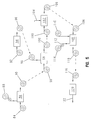
- Fig. 5 is a diagrammatic view of the method of manufacturing the biosensor of the present invention.
- Fig. 6 is a perspective view of a biosensor in accordance with another aspect of the present invention.
- Fig. 7 is an exploded view of the biosensor of Fig. 6.
- Fig. 8 is an enlarged top diagrammatic view of a biosensor in accordance with another aspect of the present invention showing one window exposing two electrode contacts.
- Fig. 9 is an enlarged top diagrammatic view of a biosensor of Fig. 8 and a diagrammatic view of a corresponding meter showing the meter including two contacts for engagement with the two exposed electrode contacts of the biosensor.
- Fig. 10 is a view similar to Fig. 8 of a biosensor in accordance with another aspect of the present invention showing five windows exposing five electrode contacts and showing a diagrammatic view of a corresponding meter including five contacts for engagement with the five exposed electrode contacts.
- Fig. 11 is an enlarged cross-sectional view of one window of the biosensor of Fig. 10 and showing one meter contact sequenced in time in order to illustrate the relative positioning of the electrode contact and the meter contact during insertion of the biosensor in the meter.
- Fig. 12 is an enlarged cross-sectional view of one window of the biosensor of Fig. 10 and showing a diagrammatic view of a switch in accordance with another aspect of the present invention.
- Fig. 13 is a view similar to Fig. 8 of a biosensor in accordance with another aspect of the present invention showing four windows exposing four electrode contacts with one closed window in phantom and showing a diagrammatic view of a corresponding meter including five contacts.
- Fig. 14 is an enlarged perspective view of a biosensor in accordance with another aspect of the present invention.
- Fig. 15 is a view taken along lines 15-15 of Fig. 14.
-
- The present invention relates to a biosensor and method of manufacturing said biosensor. This biosensor of the present invention includes opposite ends and is beneficially formed to enable a user to grasp ends without touching electrode contacts, which are themselves formed to electrically connect with a meter. Biosensors of the present invention include at least one discrete window spaced-apart from the end of the biosensor. The at least one window serves as a built-in fiducial for alignment of the biosensor, enabling easy automated process control during assembly. Further, the at least one discrete window is a significant advantage for an integrated strip handling system, since each window creates a detent, providing mechanical feedback for strip mating with meter contacts. Furthermore, when biosensor includes discrete windows, strip alignment problems are eliminated enabling multiple strip configurations to be used with a single meter. That is, the discrete windows of the biosensor prevent problems associated with closely spaced electrode pads touching the wrong meter contact. Aspects of the invention are presented in Figs. 1-15, which are not drawn to scale and wherein like components in the several views are numbered alike.
- A
biosensor 10 is shown in Figs. 1-4. The term analyte, as used herein, refers to the molecule or compound to be quantitatively determined. Non-limiting examples of analytes include carbohydrates, proteins, such as hormones and other secreted proteins, enzymes, and cell surface proteins; glycoproteins; peptides; small molecules; polysaccharides; antibodies (including monoclonal or polyclonal Ab); nucleic acids; drugs; toxins; viruses of virus particles; portions of a cell wall; and other compounds processing epitopes. The analyte of interest preferably comprises glucose. -
Biosensor 10 is shown in Fig. 1 and includesopposite ends 11, 13, either of which is available to be grasped by a user without contact with electrodes of thebiosensor 10. As shown in Fig. 2A, thebiosensor 10 includes anelectrode support substrate 12 and anelectrical conductor 14 positioned on thesubstrate 12. Theconductor 14 is disrupted to defineelectrodes Biosensor 10 also includes asensor support substrate 22 positioned on thesubstrate 12 and acover substrate 24 positioned on thesensor support substrate 22.Biosensor 10 is in the form of a disposable test strip. It is appreciated however, thatbiosensor 10 can assume any number of forms and shapes in accordance with this disclosure. -
Biosensor 10 is preferably produced from rolls of material. It is understood thatbiosensor 10 also can be constructed from individual sheets in accordance with this disclosure. Whenbiosensors 10 are produced from rolls, the selection of materials necessitates the use of materials that are sufficiently flexible for roll processing, but which are still rigid enough to give a useful stiffness to finishedbiosensor 10. - Referring to Fig. 2A, the
electrode support substrate 12 includes afirst surface 26 facing thesensor support substrate 22 and asecond surface 28. In addition,substrate 12 has opposite first andsecond ends opposite edges second ends Edge 34 ofsubstrate 12 is formed to include a generally concave-shaped notch 38. It is appreciated thatsubstrate 12 may be formed without a notch, or that the notch may take on any number of shapes and sizes in accordance with the present disclosure. -
Electrode support substrate 12 is generally rectangular in shape, it is appreciated however, thatsupport 12 may be formed in a variety of shapes and sizes in accordance with this disclosure. It is also appreciated that thesubstrate 12 need not necessarily extend the length of thesubstrate 22 as shown in Figs. 1 and 2A. In fact, thesubstrate 12 can have a shorter length so long as it is of sufficient length to position the electrodes with a channel and windows as will be described hereafter.Substrate 12 may be constructed from a wide variety of insulative materials. Non-limiting examples of insulative materials that provide desirable electrical and structural properties include glass, ceramics, vinyl polymers, polyimides, polyesters, and styrenics. Preferably,substrate 12 is a flexible polymer, such as a polyester or polyimide. A non-limiting example of a suitable material is 5 mil (125 um) thick KALADEX®, a polyethylene naphthalate film commercially available from E.I. DuPont de Nemours, Wilmington, Delaware, which is coated with gold by ROWO Coating, Henbolzhelm, Germany. It is appreciated that the thickness of thesupport 12 can be greater or less than 5 mil (125 um) and may be suitable for a number of assembly processes (e.g., lamination, etc.). -
Electrodes conductor 14 on first surface. 26 ofelectrode support substrate 12. See Figs. 2A and 3. It is appreciated thatelectrodes electrical conductor 14 include aluminum, carbon (such as graphite), cobalt, copper, gallium, gold, indium, iridium, iron, lead, magnesium, mercury (as an amalgam), nickel, niobium, osmium, palladium, platinum, rhenium, rhodium, selenium, silicon (such as highly doped polycrystalline silicon), silver, tantalum; tin, titanium, tungsten, uranium, vanadium, zinc, zirconium, mixtures thereof, and alloys, oxides, or metallic compounds of these elements. Preferably,electrical conductor 14 is selected from the following materials: gold, platinum, palladium, iridium, or alloys of these metals, since such noble metals and their alloys are unreactive in biological systems. Most preferably, theelectrical conductor 14 is gold. -
Electrodes electrical conductor 14 by laser ablation. Techniques for forming electrodes on a surface using laser ablation are known. See, for example, U.S. Patent Application Serial No. 09/411,940, titled "Laser Defined Features for Patterned Laminates and Electrodes", the disclosure of which is expressly incorporated herein by reference. Preferably,electrodes electrical conductor 14 from an area extending around the electrodes to form agap 40 of exposedsupport substrate 12. Therefore,electrodes substrate 12. Illustratively, thegap 40 has a width of about 25 µm to about 500 µm, preferably the gap has a width of about 100 µm to about 200 µm. Alternatively, it is appreciated thatelectrodes substrate 12. It is appreciated that while laser ablation is the preferred method for formingelectrodes - As shown in Fig. 2A,
electrodes electrode array 42. In addition,electrodes contact portion 44, a measurement portion positioned in thearray 42, and a lead 46 extending between thecontact 44 and the measurement portion.Contacts 44 are spaced apart fromend 32. It is appreciated that thecontacts 44 can be formed to have many lengths and can extend to end 32 or toedges substrate 12. Likewise, theleads 38 that extend from thearray 34 can be formed to have many lengths and extend to a variety of locations on theelectrode support substrate 12. It is appreciated that the configuration of the electrode array, the number of electrodes, as well as the spacing between the electrodes may vary in accordance with this disclosure and that greater than one array may be formed as will be appreciated by one of skill in the art. - As described below,
electrodes sensor support substrate 22, electrodes are enabled to be used as an antenna for telemetry, or to signify an expiration date, code number, analyte, etc.). It is also contemplated by the present disclosure to use the electrodes to examine a ratio of currents at one or more time points to determine if thebiosensor 10 has been exposed to inappropriate temperature, humidity, interferents, etc.). - As shown in Fig. 2B, the
sensor support substrate 22 ofbiosensor 10 extends to theend 32 ofsubstrate 12 to permit a user to grasp the end 11 ofbiosensor 10 without contacting theelectrodes substrate 32 may extendpast end 32 in accordance with this disclosure. Thesensor support substrate 22 is positioned to lie between theelectrode support substrate 12 and thecover substrate 24. Referring now to Fig. 4, thesensor support substrate 22 cooperates with thesupport substrate 12 and thecover 24 to expose theelectrode array 42 to a liquid sample (not shown) being applied to thebiosensor 10.Sensor support substrate 22 can be formed from any number of commercially available insulative materials. Non-limiting examples of insulative materials that provide desirable electrical and structural properties include vinyl polymers, polyimides, polyesters, and styrenics. Preferably, thesensor support substrate 22 is 10 mil (250 um) thick opaque white MELINEX® 329 plastic, a polyester commercially available from E.I. DuPont de Nemours, Wilmington, Delaware, which is coated with a thermoplastic resin (Griltex D 1698 E), commercially available from EMS-Chemie (North America) Inc., Sumter, South Carolina. It is further appreciated thatsensor support substrate 22 may be formed of a double-sided adhesive tape covered by an insulative material in accordance with the disclosure, so long as it is of a sufficient thickness to create a detent about at least onewindow 64, as will be described below. - Referring now to Fig. 2A, the
sensor support substrate 22 includes afirst surface 48 and asecond surface 50 facing theelectrode support substrate 12. When thesensor support substrate 22 is coupled to the substrate 12 afirst end 52 of thesensor support substrate 22 is aligned withend 30, asecond end 54 is aligned withend 32, anedge 56 is aligned withedge 34, and anopposite edge 58 is aligned withedge 36. - Further, the
edge 56 is formed to include anotch 60 that is shaped so as to be aligned withnotch 38 of thesubstrate 12. It is appreciated thatsubstrate 12 may be formed without a notch, or that the notch may take on any number of shapes and sizes in accordance with the present disclosure. Anopening 62 extends from thenotch 60 toward theedge 58. When thesensor support substrate 22 is coupled to thesubstrate 12, as shown in Figs. 1 and 4, thesubstrates electrode array 42 are positioned to lie in general alignment with theopening 62 and are thus positioned in the channel 78 to expose at least a portion of theelectrodes electrode array 42. An interior border 80 defines theopening 62. The width of the interior border 80 can vary in accordance with this disclosure. - The
sensor support substrate 22 extends to theend 32 ofsubstrate 12 and is formed to expose theelectrode contacts 44 for engagement with ameter 124. A non-limiting example of such a meter is shown diagrammatically in Fig. 10. Referring now to Fig. 1,sensor support substrate 22 includeswindows 64 that extend between first andsecond surfaces window 64 creates a detent insensor support substrate 22 and is spaced apart fromend 54. This detent provides mechanical feedback for strip mating with meter contacts and increases the rigidity of thesubstrate 22. Further, the positioning of thewindows 64 enables a user to grasp the end 11 of thebiosensor 10 without touching theelectrode contacts 44. Thus, the inadvertent deposit of skin oils, dirt, skin cells, etc. onto theelectrical contacts 44 through simple handling of thebiosensor 10 is prevented. - In addition, at least one
window 64 may be used to perform alignment of thesubstrates window 64 may be used to perform alignment for other manufacturing processes such as dispensing, labeling, cutting, punching, etc. Moreover, it is appreciated thatwindows 64 can take on a variety of shapes and sizes in accordance with the present disclosure. Illustratively,windows 64 are formed to be slightly larger than therespective contacts 44. A non-limiting example of dimensions ofsuitable windows 64 when contacts have a width of about 1mm and a length of about 2mm, is a width of about 1.5 mm and a length of about 2.5mm. In addition, while threewindows 64 are shown, it is appreciated thatbiosensor 10 can be formed with greater than three windows or as few as one window in accordance with the present disclosure. Non-limiting examples of which include windows illustrated in Figs. 8-10, and 13-15. -
Sensor support substrate 22 is coupled to theelectrode support substrate 12 as shown in Fig. 1. The thermoplastic resin onsurface 48 permits thesubstrate 22 to be heat-sealed to theconductor 14coating substrate 12. It is appreciated thatsubstrates substrate 12 where theconductor 14 has been removed) in accordance with this disclosure. It is also appreciated thatfirst surface 50 ofsubstrate 22 may be printed with, for example, product labeling or instructions for use in accordance with this disclosure. - The
cover substrate 24 is coupled to thespacer support 22 across theopening 62. See Fig. 1. Thecover substrate 24 ofbiosensor 10 includes afirst surface 66 facingsubstrate 12, an oppositesecond surface 68 and a vent 69 extending betweensurfaces cover substrate 24 has opposite first and second ends 70, 72 andedges Edge 74 is preferably generally concave shape for alignment withnotches substrates edge 74 may take on any number of shapes and sizes in order to be in general alignment with the shape ofnotches cover substrate 24 is formed of a flexible polymer and preferably from a polymer such as an adhesive coated polyethylene terephthalate (PET)―polyester. A non-limiting example of a suitable PET is 2 mil (50 um) thick clear PET film one side of which is coated with a hydrophilic pressure-sensitive adhesive (Product # ARcare 8877) commercially available from Adhesives Research, Inc. Glen Rock, Pennsylvania. - The
cover substrate 24 is formed to cooperate with thesensor support substrate 22 and thesupport substrate 12 to define a channel 78 extending fromedges electrode array 42. The channel 78 is preferably a capillary channel that is formed to transport a fluid sample from the user to theelectrode array 42. As shown in Fig. 4, the channel 78 extends fromedges opening 62. It is appreciated that the channel 78 can extend from any number of locations ofbiosensor 10 to thearray 42. It is also appreciated that channel 78 may also be formed from cooperation between only thesensor support substrate 22 and thesupport substrate 12. - An
electrochemical reagent 82 is positioned on thearray 42. Thereagent 82 provides electrochemical probes for specific analytes. The choice of thespecific reagent 82 depends on the specific analyte or analytes to be measured, and are well known to those of ordinary skill in the art. An example of a reagent that may be used inbiosensor 10 of the present invention is a reagent for measuring glucose from a whole blood sample. A non-limiting example of a reagent for measurement of glucose in a human blood sample contains 62.2 mg polyethylene oxide (mean molecular weight of 100-900 kilo Daltons), 3.3 mg NATROSOL 244M, 41.5 mg AVICEL RC-591 F, 89.4 mg monobasic potassium phosphate, 157.9 mg dibasic potassium phosphate, 437.3 mg potassium ferricyanide, 46.0 mg sodium succinate, 148.0 mg trehalose, 2.6 mg TRITON X-100 surfactant, and 2,000 to 9,000 units of enzyme activity per gram of reagent. The enzyme is prepared as an enzyme solution from 12.5 mg coenzyme PQQ and 1.21 million units of the apoenzyme of quinoprotein glucose dehydrogenase. This reagent is further described in U.S. Patent No. 5,997,817, the disclosure of which is expressly incorporated herein by reference. - Non-limiting examples of enzymes and mediators that may be used in measuring particular analytes in
biosensor 10 are listed below in Table 1.Analyte Enzymes Mediator (Oxidized Form) Additional Mediator Glucose Glucose Dehydrogenase and Diaphorase Ferricyanide Glucose Glucose-Dehydrogenase (Quinoprotein) Ferricyanide Cholesterol Cholesterol Esterase and Cholesterol Oxidase Ferricyanide 2,6-Dimethyl-1,4-Benzoquinone 2,5-Dichloro-1,4-Benzoquinone or Phenazine Ethosulfate HDL Cholesterol Cholesterol Esterase and Cholesterol Oxidase Ferricyanide 2,6-Dimethyl-1,4 Benzoquinone 2,5-Dichloro-1,4-Benzoquinone or Phenazine Ethosulfate Triglycerides Lipoprotein Lipase, Glycerol Kinase, and Glycerol-3-Phosphate Oxidase Ferricyanide or Phenazine Ethosulfate Phenazine Methosulfate Lactate Lactate Oxidase Ferricyanide 2,6-Dichloro-1,4-Benzoquinone Lactate Lactate Dehydrogenase and Diaphorase Ferricyanide Phenazine Ethosulfate, or Phenazine Methosulfate Lactate Dehydrogenase Diaphorase Ferricyanide Phenazine Ethosulfate, or Phenazine Methosulfate Pyruvate Pyruvate Oxidase Ferricyanide Alcohol Alcohol Oxidase Phenylenediamine Bilirubin Bilirubin Oxidase 1-Methoxy-Phenazine Methosulfate Uric Acid Uricase Ferricyanide - In some of the examples shown in Table 1, at least one additional enzyme is used as a reaction catalyst. Also, some of the examples shown in Table 1 may utilize an additional mediator, which facilitates electron transfer to the oxidized form of the mediator. The additional mediator may be provided to the reagent in lesser amount than the oxidized form of the mediator. While the above assays are described, it is contemplated that current, charge, impedance, conductance, potential, or other electrochemically indicated property of the sample might be accurately correlated to the concentration of the analyte in the sample with
biosensor 10 in accordance with this disclosure. - A plurality of
biosensors 10 are typically packaged in a vial, usually with a stopper formed to seal the vial. It is appreciated, however, thatbiosensors 10 may be packaged individually, or biosensors can be folded upon one another, rolled in a coil, stacked in a cassette magazine, or packed in blister packaging. -
Biosensor 10 is used in conjunction with the following: - 1. a power source in electrical connection with
contacts 44 and capable of supplying an electrical potential difference betweenelectrodes - 2. a meter in electrical connection with
contacts 44 and capable of measuring the diffusion limited current produced by oxidation of the reduced form of the mediator with the above-stated electrical potential difference is applied. -
- The meter will normally be adapted to apply an algorithm to the current measurement, whereby an analyte concentration is provided and visually displayed. Improvements in such power source, meter, and biosensor system are the subject of commonly assigned U.S. Pat. No. 4,963,814, issued Oct. 16, 1990; U.S. Pat. No. 4,999,632, issued Mar. 12, 1991; U.S. Pat. No. 4,999,582, issued Mar. 12, 1991; U.S. Pat. No. 5,243,516, issued Sep. 7, 1993; U.S. Pat. No. 5,352,351, issued Oct. 4, 1994; U.S. Pat. No. 5,366,609, issued Nov. 22, 1994; White et al., U.S. Pat. No. 5,405,511, issued Apr. 11, 1995; and White et al., U.S. Pat. No. 5,438,271, issued Aug. 1, 1995, the disclosures of each of which are expressly hereby incorporated by reference.
- Many fluid samples may be analyzed. For example, human body fluids such as whole blood, plasma, sera, lymph, bile, urine, semen, cerebrospinal fluid, spinal fluid, lacrimal fluid and stool specimens as well as other biological fluids readily apparent to one skilled in the art may be measured. Fluid preparations of tissues can also be assayed, along with foods, fermentation products and environmental substances, which potentially contain environmental contaminants. Preferably, whole blood is assayed with this invention.
- As shown in Fig. 5,
biosensor 10 is manufactured using six distinct processes. In process one, a roll of sensorsupport substrate material 84 is fed into a window punch andweb slit station 86. In thestation 86, thewindows 64 and theopening 62 are created through the sensor support substrates in the web and the web is slit to its final dimension in the station. The trim, from the edges of the web of material is removed from the material and wound into aroll 88. Upon leaving thestation 86, the punched sensor support substrates connected to one another via a web are wound into aroll 90. - In process two, a roll of metallized
electrode support material 92 is fed into an ablation/washing and dryingstation 94. A laser system capable of ablatingsupport 12 is known to those of ordinary skill in the art. Non-limiting examples of which include excimer lasers, with the pattern of ablation controlled by mirrors, lenses, and masks. A non-limiting example of such a custom fit system is the LPX-300 or LPX-200 both commercially available from LPKF Laser Electronic GmbH, of Garbsen, Germany. - In the
ablation station 94, the metallic layer of the metallized film is ablated in a pre-determined pattern, to form a ribbon of support material withisolated electrode patterns 96. To ablateelectrodes gaps 40 in 50 nmthick gold conductor ablation station 94, the ribbon is also passed through an optional inspection system where both optical and electrical inspection can be made. The system is used for quality control in order to check for defects. - Next, in process three, the roll of punched
sensor support substrates 90 is fed into a cutting andlamination station 98. At the same time, the ribbon of support material withisolated electrode patterns 96 is fed into thestation 98. The thermoplastic resin coated first surface of thesensor support substrates 90 is applied to the electrode support substrate material so that thewindows 64 are in general alignment with therespective contacts 44 and theopenings 62 are in general alignment with thearrays 42. It is appreciated that thewindows 64 may in fact be used as a built-in fiducial for alignment thesensor support substrates 90 with the ribbon of support material. Once aligned, the web ofsensor support substrates 90 is heat-sealed to the ribbon ofsupport material 96 to formsubassembly 100. - In process four, the
subassembly 100 is fed into areagent dispensing station 102. A reagent that has been compounded is fed, as shown byarrow 104, into the dispensingstation 102 where it is applied in a liquid form in multiple shots to thearray 42. It is appreciated, however, that the reagent can be applied in a single shot by a custom fit precision dispensing station available from Fluilogic Systems Oy, Espoo, Findland. Reagent application techniques are well known to one of ordinary skill in the art as described in U.S. Patent No. 5,762,770, the disclosure of which is expressly incorporated herein by reference. It is appreciated that reagents may be applied to thearray 42 in a liquid or other form and dried or semi-dried onto thearray 42 in accordance with this disclosure. A reagent-coatedsubassembly 106 then exits thestation 102. - In process five, the reagent-coated
subassembly 106 is fed into a second cutting andlamination station 108. At the same time, a ribbon ofcover material 110 is fed intostation 108. A liner on one side of theribbon 110 is removed in thestation 108 and rewound overguide roll 112 into a roll 114 for discard. The ribbon ofcover material 110 and thesubassembly 106 are aligned so that thecover material 110 lies across theelectrode arrays 42 to form an assembledmaterial 116. - In process six, the assembled
material 116 is fed into a sensor punch/pack station 120 where thematerial 116 is cut to formindividual biosensors 10. Thebiosensors 110 are sorted and packed into vials. Each vial is then closed with a stopper to give packaged biosensor strips as shown byarrow 122. - In use, for example, a user of
biosensor 10 places a finger having a blood collection incision againstrespective notches edge 74adjacent opening 62. Capillary forces pull a liquid sample flowing from the incision into theopening 62 and through the capillary channel 78 across thereagent 82 and thearray 42. The liquid sample dissolves thereagent 82 and engages thearray 42 where the electrochemical reaction takes place. - The user then inserts the
biosensor 10 into the meter 124 (see, for example Fig. 10) where an electrical connection is made between theelectrode contacts 44 exposed bywindows 64 and threecorresponding meter contacts 126 of themeter 124. Referring now to Fig. 11, a non-limiting example of asuitable meter contact 126 is illustrated.Meter contact 126 includes anelectrode engagement portion 128 that is formed of an electrically conductive material and apivot portion 130. Eachmeter contact 126 is spring-loaded so that it pivots over theedge 54 of thespacer support substrate 22 when thebiosensor 10 is moved into themeter 124, as shown for example byarrow 132, and rides across thesurface 50 of said substrate. When, however, theelectrode engagement portion 128 encounters awindow 64, themeter contact 126 pivots on thepivot portion 130 so that theportion 128 engages a corresponding electrode exposed by thewindow 64 and creates an electrically conductive connection between the exposed electrode and the contact. It is appreciated that the illustratedmeter 124 includes greater than threemeter contacts 126, two of which will rest upon thesecond surface 50 of thespacer substrate 22 when thebiosensor 10 is inserted into themeter 124. It is appreciated thatbiosensor 10 may be used with a variety of meters, which may include greater or less than five meter contacts in accordance with this disclosure. - Moreover, it is appreciated that the
biosensor 10 also may be inserted into themeter 124 at a variety of time periods including prior to the sample flowing into theopening 62. Once the electrochemical reaction is complete, a power source (e.g., a battery) applies a potential difference between theelectrodes current measuring meter 124 measures the diffusion-limited current generated by the oxidation of the reduced form of the mediator at the surface of the working electrode as described above. - The measured current may be accurately correlated to the concentration of the analyte in sample when the following requirements are satisfied:
- 1. The rate of oxidation of the reduced form of the mediator is governed by the rate of diffusion of the reduced form of the mediator to the surface of the working electrode.
- 2. The current produced is limited by the oxidation of reduced form of the mediator at the surface of the working electrode.
-
- It is appreciated that the
meter 124 can be designed to be utilized with a number of different biosensors with a variety of different electrodes or contacts. Non-limiting examples of alternative biosensors may require temperature or hematocrit compensation, others might utilize a one, two, four, five or more electrode configuration, others might require coding or expiration information exchange with the meter, etc. Furthermore, themeter 124 may be formed to measure multiple analytes simultaneously on a single strip (e.g., glucose and fructosamine, glucose and ketones, HDL and total cholesterol, etc.). For example, the presence and location of thecontacts 44 exposed through thewindows 64 could readily identify such a biosensor to the meter as a glucose/ketone assay). Thus, by using different combinations of window placement onbiosensor 10, new analytes may easily be added to the meter's applications. - In another aspect of the invention, a
biosensor 210 is provided in accordance with the present invention.Biosensor 210 is shown in Figs. 6-7 and includes opposite ends 211, 213, either of which is available to be grasped by a user without contact with electrodes of thebiosensor 210.Biosensor 210 includes anelectrode support substrate 212 that supports theelectrical conductor 14 described above with reference tobiosensor 10. Theconductor 14 is disrupted to defineelectrodes Biosensor 210 also includes asensor support substrate 222 positioned on thesubstrate 212 and acover substrate 224 positioned on thesensor support substrate 222.Biosensor 210 is formed in a variety of shapes and sizes and from materials similar tobiosensor 10 as described above. - Referring to Fig. 7, the
edge 34 of theelectrode support substrate 212 is formed to include anotch 238. It is appreciated thatsubstrate 212 may be formed without a notch, or that the notch may take on any number of shapes and sizes in accordance with the present disclosure.Electrodes conductor 14 similar toelectrodes Electrodes electrode array 242. In addition,electrodes contact 244 and a lead 246 extending between thecontact 244 and thearray 242.Contacts 244 are spaced apart fromend 32. It is appreciated that thecontacts 244 can be formed to have many lengths and can extend to end 32 or toedges substrate 212. Likewise, theleads 246 that extend from thearray 242 can be formed to have many lengths and extend to a variety of locations on theelectrode support substrate 12. It is appreciated that the configuration of the electrode array, the number of electrodes, as well as the spacing between the electrodes may vary in accordance with this disclosure and that a greater than one array may be formed as will be appreciated by one of skill in the art. -
Sensor support substrate 222 ofbiosensor 210 is positioned to lie betweensupport substrate 212 andcover substrate 224.Sensor support substrate 222 extends to theend 32 to permit a user to grasp theend 213 of thebiosensor 210 without touching theelectrodes sensor support substrate 222 cooperates with thesupport substrate 212 and thecover 224 to expose theelectrode array 242 to a liquid sample being applied to thebiosensor 210.Sensor support substrate 222 may have a variety of lengths and is formed from materials similar tosubstrate 22, as described above. - As shown in Fig. 7, the
edge 56 of thesensor support substrate 22 is formed to include anotch 260. It is appreciated thatsubstrate 212 may be formed without a notch, or that the notch may take on any number of shapes and sizes in accordance with the present disclosure. Anopening 262 extends from thenotch 260 toward theedge 58. When thesensor support substrate 222 is coupled tosubstrate 212, theelectrode array 242 is positioned to lie in general alignment with theopening 262, exposing at least a portion of theelectrode array 242. Aninterior border 280 defines theopening 262. The width of theinterior border 280 can vary in accordance with this disclosure. - The
sensor support substrate 222 extends to theend 32 ofsubstrate 212 and is formed to expose theelectrode contacts 244 for engagement with ameter 282, as shown for example in Fig. 9. Referring now to Figs. 7 and 9, thesensor support substrate 222 includesdiscrete windows 264 that extend between first andsecond surfaces window 264 is spaced apart fromend 54 in order to enable a user to grasp theend 54 of thesensor support substrate 222 without touching theelectrode contacts 244. Thus, the inadvertent deposit of skin oils, dirt, skin cells, etc. onto theelectrical contacts 244 through simple handling of thebiosensor 210 is prevented. In addition, at least onewindow 264 may be used to perform alignment of thesubstrates window 264 may be used to perform alignment for other manufacturing processes such as dispensing, labeling, cutting, punching, etc. Moreover, it is appreciated thatwindows 264 can take on a variety of shapes and sizes as described above with reference towindows 64 in accordance with the present disclosure. - As show in Fig. 6, the
cover substrate 224 is coupled to thespacer support 222 and extends across theopening 262. Theedge 74 of thecover substrate 224 formed to include anotch 276. It is appreciated thatsubstrate 224 may be formed without a notch, or that the notch may take on any number of shapes and sizes in accordance with the present disclosure. When thecover substrate 224 is coupled to thesensor support substrate 222, aninterior border 282 is aligned with the entrance to theopening 262. The width of theinterior border 282 can vary in accordance with this disclosure. -
Biosensor 210 is manufactured in a similar manner tobiosensor 10, except for the following differences: First, in the window punch andweb slit station 86, twowindows 264 and anopening 262 that has aborder 280 with corners are formed in the web of thesensor support substrate 90. Second, in the ablation/washing and dryingstation 94, twoelectrodes substrate 212.Cover material 110 is then fed into the second cutting andlamination station 108 along with the reagent-coatedsubassembly 106 as discussed above with reference tobiosensor 10. In addition, the ribbon of thecover material 110 and thesubassembly 106 are aligned to form an assembledmaterial 116. The assembledmaterial 116 is then fed into the sensor punch/pack station 120 where thematerial 116 is cut to formindividual biosensors 210 and packed as described above with reference tobiosensors 10. - In use, for example, a user of
biosensor 210 places a finger having a blood collection incision againstarray 242 exposed by opening 262. The liquid sample flowing from the incision dissolves thereagent 82 and engages thearray 42 where the electrochemical reaction takes place. Cooperation between thebiosensor 210 and themeter 282 are similar to that described above with reference tobiosensor 10.Meter 282, however, includes twometer contacts 126. Eachmeter contact 126 is formed to pivot overedge 54 of thesensor support substrate 222 when thebiosensor 210 is inserted into themeter 282. Thesemeter contacts 126 ride across thesurface 50 and pivot into alignedwindows 264 so that theportion 128 engages a corresponding electrode exposed by thewindow 264 and creates an electrically conductive connection between the exposed electrode and the contact. - In accordance with another aspect of the present invention, a
biosensor 310 is provided and is illustrated in Fig. 8. Thebiosensor 310 is constructed and manufactured identically tobiosensor 210 except itsspacer support substrate 222 is formed to include onewindow 364. Thiswindow 364 exposes bothelectrodes meter 282 illustrated in Fig. 9.Biosensor 310 is also used in a manner similar tobiosensor 210, except that upon insertion of thebiosensor 310 into themeter 282, themeter contacts 126 each pivot into thesingle window 264 for engagement with an aligned electrode to create an electrically conductive connection between the exposed electrode and the contact. - In accordance with another aspect of the present invention, a
biosensor 410 is provided and is illustrated in Figs. 10-12. As shown in Figs. 11 and 12,biosensor 410 includes anelectrode support substrate 412 that supports theelectrical conductor 14 as described above with reference tobiosensor 10. Referring now to Fig. 10, theconductor 14 is disrupted to defineelectrodes Biosensor 410 also includes asensor support substrate 422 positioned on thesubstrate 412.Biosensor 410 may also include a cover substrate, as shown for example in Figs. 2 and 7, positioned on thesensor support substrate 422.Biosensor 410 is formed in a variety of shapes and sizes and from materials similar tobiosensor 10 as described above. -
Electrodes conductor 14 similar toelectrodes electrode contact 444 spaced apart fromend 32 and a lead 446 extending from thecontact 444. It is appreciated that thecontacts 444 can be formed to have many lengths and can extend to any number of locations onsubstrate 212. Likewise, theleads 246 that extend from thecontacts 444 can be formed to have many lengths and extend to a variety of locations on theelectrode support substrate 412. It is appreciated that the configuration of the electrodes may vary as discussed above with reference tobiosensors -
Sensor support substrate 422 ofbiosensor 410 extends to theend 32 of theelectrode support substrate 412.Substrate 422, may however have a variety of lengths and be formed from materials similar tosubstrate 22, as described above. In addition, thesensor support substrate 422 is formed to expose theelectrode contacts 444 for engagement with themeter 124. As shown in Fig. 10, thesensor support substrate 422 includes fivediscrete windows 464.Windows 464 extend between first andsecond surfaces window 264 is spaced apart fromend 54. Similar towindows window 264 may be used to perform alignment for a variety of manufacturing processes. Moreover, it is appreciated thatwindows 464 can take on a variety of shapes and sizes as described above with reference towindows 64 in accordance with the present disclosure. -
Biosensor 410 is manufactured in a similar manner tobiosensor 210, except for the following differences: First, in the window punch andweb slit station 86, fivewindows 464 are formed in the web of thesensor support substrate 90. Second, in the ablation/washing and dryingstation 94, fiveelectrodes substrate 412. - The
biosensor 410 is used in a manner similar tobiosensors biosensor 410 and themeter 124 are similar to that described above with reference tobiosensor 10. Eachmeter contact 126 is formed to pivot overedge 54 of thesensor support substrate 422 when thebiosensor 410 is inserted into themeter 124. Thesemeter contacts 126 ride across thesurface 50 and pivot into alignedwindows 464 so that theportion 128 engages a corresponding electrode exposed by thewindow 464 and creates an electrically conductive connection between the exposed electrode and the contact. - A non-limiting example of an alternative to
meter contact 126 is illustrated diagrammatically in Fig. 12. Thealternative meter contact 466 may be a mechanical switch or an optical (LED) switch. Contact 466 may be used for an automatic on/off switch, to signify which type of biosensor has been inserted into the meter, as a fail safe for the meter contact, and/or as a positive mating mechanism. It is appreciated that a variety of commercially available mechanical switches and LED switches may be used in accordance with this disclosure. - In use, the meter is turned on and the biosensor is inserted into the meter. It is appreciated that the user may turn on the meter, or it may turn on automatically upon insertion of the biosensor. The LED emits a light that is directed through a lens towards the biosensor. The light is reflected off of the exposed
conductor 14, through the lens, and toward the photodiode. The photodiode measures the intensity of the light that is reflected back from theconductor 14 and generates a corresponding voltage waveform. A decoder deciphers this waveform and translates it into a reading of the conductor. It is appreciated that many commercially available optical readers may be used in accordance with the present invention. Preferably, the optical reader will be a custom fit reader. - In addition, in accordance with another aspect of the present invention, a
biosensor 510 is provided and is illustrated in Fig. 13. Thebiosensor 510 is constructed and manufactured identically tobiosensor 410 except itsspacer support substrate 522 is formed to include four windows 564 instead of five. Thus, one electrode, a non-limiting example of which iselectrode 416, remains covered by thespacer support substrate 522. It is appreciated that greater than one electrode may be covered by thesubstrate 522.Biosensor 510 is used in a manner similar tobiosensor 410, except that upon insertion of thebiosensor 510 into themeter 124, fourmeter contacts 126 pivot into correspondingwindows 464 for engagement with alignedelectrodes meter contact 126 that is aligned withelectrode 416 remains resting upon thesecond surface 50 of thespacer support substrate 522. - In another aspect of the invention, a
biosensor 610 is provided in accordance with the present invention.Biosensor 610 is shown in Figs. 14 and 15 and includes anelectrode support substrate 612 that includes first andsecond surfaces electrical conductor 14 formed as described above with reference tobiosensor 10. Theconductor 14 is disrupted to defineelectrodes first surface 626 andelectrodes second surface 628.Biosensor 610 also includessensor support substrates substrate 630 extends acrosselectrodes substrate 632 extends across theelectrodes Biosensor 610 may be formed in a variety of shapes and sizes and from materials similar tobiosensor 10 as described above. - Referring to Fig. 15, the
electrodes electrodes conductor 14 similar toelectrodes biosensor 210.Electrodes electrodes contact 644 and a lead 646 extending from thecontact 644. See Fig. 14.Contacts 644 are spaced apart fromend 32. It is appreciated that thecontacts 644 can be formed to have many lengths and can extend to end 32 or toedges substrates leads 646 can be formed to have many lengths and extend to a variety of locations on theelectrode support substrate 612. It is appreciated that the number of electrodes as well as the spacing between the electrodes may vary in accordance with this disclosure as will be appreciated by one of skill in the art. It is also appreciated that theelectrodes electrodes -
Sensor support substrates biosensor 610 each extend to theend 32 of theelectrode support substrate 612. It is appreciated, however, the relative positioning between thesubstrates electrode support substrate 612 may vary in accordance with this disclosure. Moreover, thesensor support substrates substrate 22, as described above. As shown in Fig. 15, thesensor support substrate 630 is formed to expose thecontacts 644 of theelectrodes meter contacts 126. Likewise, thesensor support substrate 632 is formed to expose thecontacts 644 of theelectrodes meter contacts 126. - The support substrates 630, 632 are formed to include
discrete windows window second surfaces end 54. It is appreciated that at least one of the windows may be used to perform alignment of thesensor support substrate 630 with theelectrode support substrate 612 and thesensor support substrate 632 with theelectrode support substrate 612. It is also appreciated that at least one window may be used to perform alignment for other manufacturing processes such as dispensing, labeling, cutting, punching, etc. Moreover, it is appreciated that thewindows windows 64 in accordance with the present disclosure. -
Biosensor 610 is manufactured in a similar manner tobiosensor 10, except for the following differences: - First, in the window punch and
web slit station 86, twowindows 648 are formed in the web of the sensor support substrate. Likewise, either in thestation 86, or in a second slit station, twowindows 650 are formed in a second web of a sensor support substrate. Second, in process two, a roll of electrode support material that is metallized on first andsecond surfaces station 94. In theablation station 94, each metallic layer of the metallized film is ablated in a pre-determined pattern, to form a ribbon of support material with isolated electrode patterns onsurfaces biosensor 10. - Next, in process three, the first and second rolls of punched sensor support substrates are fed into a cutting and
lamination station 98. At the same time, the ribbon of support material with isolated electrode patterns is fed into thestation 98. The thermoplastic resin coated first surface of the sensor support substrates are each applied to the first andsecond surfaces windows contacts 644. It is appreciated that thewindows - In process four, the subassembly is fed into a first
reagent dispensing station 102. A reagent that has been compounded is fed, as shown byarrow 104, into the dispensingstation 102 where it is applied in a liquid form in multiple shots to the array on thefirst surface 626. The subassembly is then fed into a second reagent dispensing station (not shown) where a second reagent that has been compounded is fed into the dispensing station where it is applied in a liquid form in multiple shots to the array on thesecond surface 628. It is appreciated that the reagent can be applied in a single shot by a custom fit precision dispensing station available from Fluilogic Systems Oy, Espoo, Findland. Reagent application techniques are as described above with reference tobiosensor 10. It is appreciated that reagents may be applied to the arrays in a liquid or other form and dried or semi-dried onto the arrays in accordance with this disclosure. A reagent-coated subassembly then exits the second station. - In process five, the reagent-coated subassembly is fed into a second cutting and
lamination station 108. At the same time, two ribbons of cover material are fed into thestation 108. A liner on one side of each ribbon is removed in thestation 108. The ribbons of cover material and the subassembly are aligned so that one ribbon of cover material lies across a portion of theelectrodes electrodes individual biosensors 610 as described above with reference tobiosensor 10. -
Biosensor 610 is used in a manner similar tobiosensor 210. Likewise, cooperation between thebiosensor 610 and a meter are similar to that described above with reference tobiosensor 10. A meter suitable for use withbiosensor 610 will include meter contacts that will become aligned withwindows biosensor 610 is inserted into the meter. - The processes and products described above include
disposable biosensors biosensor 10 can be manufactured in a variety of shapes and sizes and be used to perform a variety of assays, non-limiting examples of which include current, charge, impedance conductance, potential or other electrochemical indicative property of the sample applied to biosensor. - Although the invention has been described in detail with reference to a preferred embodiment, variations and modifications exist within the scope and spirit of the invention, on as described and defined in the following claims.
Claims (26)
- A biosensor (10) comprising:an electrode support substrate (12),electrodes (16, 18, 20) positioned on the electrode support, each electrode including a meter-contact portion and a measurement portion, anda sensor support substrate (22) cooperating with the electrode support substrate to define a channel in alignment with the measurement portion of the electrodes, the sensor support substrate including opposite ends and at least one window (64), the at least one window being spaced-apart from the ends and in alignment with the meter-contact portion of at least one of the electrodes.
- The biosensor of claim 1 further comprising a cover substrate (24) coupled to the sensor support substrate.
- The biosensor of claim 2 wherein the cover substrate cooperates with the electrode support substrate and the sensor support substrate to define the channel.
- The biosensor of claim 1 further comprising a reagent (82) positioned on the electrode support substrate and spaced-apart from the meter-contact portion of the electrodes.
- The biosensor of claim 1 wherein the dimensions of at least one of the windows are greater than the dimensions of the meter-contact portion of the respective electrodes.
- The biosensor of claim 1 wherein the electrode support substrate includes a greater number of electrodes than the sensor support substrate includes windows.
- The biosensor of claim 1 further comprising a second sensor support substrate coupled to the electrode support substrate, the second sensor support substrate including opposite ends and at least one window, the at least one window being spaced-apart from the ends and in alignment with the meter-contact portion of at least one of the electrodes.
- A method of forming a biosensor (10), the method comprising the steps of:forming electrodes (16, 18, 20) on a first surface of an electrode support substrate (12), each electrode including a meter-contact portion and a measurement portion,forming a sensor support substrate (22) having opposite ends and at least one window (64) spaced apart from the opposite ends,coupling the sensor support and the electrode support substrate together so that the at least one window is aligned with the meter-contact portion of the electrodes, andapplying a reagent to the measurement portion of the electrodes.
- The method of claim 8 wherein the windows are used to perform alignment of the sensor support substrate with the sensor support substrate.
- The method of claim 8 further comprising the step of forming electrodes on a second surface of the electrode support substrate.
- The method of claim 10 further comprising the steps of forming a second sensor support substrate and coupling the second sensor support substrate to the second surface of the electrode support substrate.
- The method of claim 11 wherein the sensor support substrate includes windows and the coupling step includes aligning the windows of the sensor support substrate with the electrodes on the second surface.
- The method of claim 8 wherein the electrodes are formed on the electrode support substrate with a laser.
- The method of claim 8 wherein an equal number of electrodes are formed on the electrode support substrate as are windows formed in the sensor support substrate.
- The method of claim 8 wherein a greater number of electrodes are formed on the electrode support substrate than are windows formed in the sensor support substrate.
- The method of claim 15 wherein at least one window is formed to expose greater than one electrode.
- The method of claim 8 wherein an equal number of electrodes are formed on the electrode support substrate as are windows formed in the sensor support substrate.
- The method of claim 8 wherein a greater number of windows are formed on the electrode support substrate as are electrodes formed on the electrode support substrate
- The method of claim 8 further comprising forming an opening in the sensor support substrate and the coupling step includes aligning the opening with the measurement portion of the electrodes.
- The method of claim 19 further comprising coupling a cover substrate to the spacer support substrate so that the cover extends across the opening.
- A biosensor (10) comprising:an electrode support substrate (12),electrodes (16, 18, 20) positioned on the electrode support substrate (12), each electrode including a meter-contact portion and a measurement portion,a sensor support substrate (22) coupled to the electrode support substrate, the sensor support substrate including opposite ends, an opening in alignment with the measurement portion of the electrodes and at least one window (64) spaced-apart from the ends and in alignment with the meter-contact portion of the electrodes, anda cover coupled to the sensor support substrate.
- The biosensor of claim 21 wherein the cover extends across the opening.
- The biosensor of claim 21 wherein the electrode support substrate includes opposite first and second ends and the meter-contact portions are spaced apart from ends.
- The biosensor of claim 21 wherein the electrode support substrate includes a greater number of electrodes than the sensor support substrate includes windows.
- The method of claim 21 wherein the electrode support substrate includes an equal number of electrodes as windows formed in the sensor support substrate.
- The biosensor of claim 21 further comprising a second sensor support substrate coupled to the electrode support substrate, the second sensor support substrate including opposite ends and at least one window, the at least one window being spaced-apart from the ends and in alignment with the meter-contact portion of at least one of the electrodes.
Applications Claiming Priority (2)
| Application Number | Priority Date | Filing Date | Title |
|---|---|---|---|
| US103027 | 2002-03-21 | ||
| US10/103,027 US6866758B2 (en) | 2002-03-21 | 2002-03-21 | Biosensor |
Publications (2)
| Publication Number | Publication Date |
|---|---|
| EP1347058A2 true EP1347058A2 (en) | 2003-09-24 |
| EP1347058A3 EP1347058A3 (en) | 2009-12-30 |
Family
ID=27788362
Family Applications (1)
| Application Number | Title | Priority Date | Filing Date |
|---|---|---|---|
| EP03006031A Withdrawn EP1347058A3 (en) | 2002-03-21 | 2003-03-19 | Electrochemical biosensor with connector windows |
Country Status (2)
| Country | Link |
|---|---|
| US (2) | US6866758B2 (en) |
| EP (1) | EP1347058A3 (en) |
Cited By (10)
| Publication number | Priority date | Publication date | Assignee | Title |
|---|---|---|---|---|
| WO2011127905A1 (en) * | 2010-04-13 | 2011-10-20 | Fraunhofer-Gesellschaft Zur Förderung Der Angewandten Forschung E.V. Angewandten Forschung E.V. | Ion-sensitive sensor element |
| CN104160035A (en) * | 2012-03-02 | 2014-11-19 | 西拉格国际有限责任公司 | Test strip with stacked unidirectional contact |
| US9977039B2 (en) | 2011-02-15 | 2018-05-22 | Hemosonics Llc | Devices, systems and methods for evaluation of hemostasis |
| US10578579B2 (en) | 2014-11-26 | 2020-03-03 | Universitat Autonoma De Barcelona | Probe for the continuous monitoring in real time of chemical parameters of interest directly in the ground and system for the continuous monitoring in real time of said chemical parameters of interest |
| US10962524B2 (en) | 2011-02-15 | 2021-03-30 | HomoSonics LLC | Characterization of blood hemostasis and oxygen transport parameters |
| US10996230B2 (en) | 2008-12-23 | 2021-05-04 | C A Casyso Gmbh | Cartridge device for a measuring system for measuring viscoelastic characteristics of a sample liquid, a corresponding measuring system, and a corresponding method |
| US11054396B2 (en) | 2011-05-19 | 2021-07-06 | Hemosonics Llc | Hemostasis analyzer |
| US11327069B2 (en) | 2014-09-29 | 2022-05-10 | Ca Casyso Gmbh | Blood testing system and method |
| US11366093B2 (en) | 2017-04-20 | 2022-06-21 | Hemosonics, Llc | Disposable system for analysis of hemostatic function |
| US11456071B2 (en) | 2010-04-08 | 2022-09-27 | Hemosonics Llc | Hemostatic parameter display |
Families Citing this family (98)
| Publication number | Priority date | Publication date | Assignee | Title |
|---|---|---|---|---|
| US6036924A (en) | 1997-12-04 | 2000-03-14 | Hewlett-Packard Company | Cassette of lancet cartridges for sampling blood |
| US6391005B1 (en) | 1998-03-30 | 2002-05-21 | Agilent Technologies, Inc. | Apparatus and method for penetration with shaft having a sensor for sensing penetration depth |
| US6616819B1 (en) * | 1999-11-04 | 2003-09-09 | Therasense, Inc. | Small volume in vitro analyte sensor and methods |
| US20060091006A1 (en) * | 1999-11-04 | 2006-05-04 | Yi Wang | Analyte sensor with insertion monitor, and methods |
| US8641644B2 (en) | 2000-11-21 | 2014-02-04 | Sanofi-Aventis Deutschland Gmbh | Blood testing apparatus having a rotatable cartridge with multiple lancing elements and testing means |
| US7025774B2 (en) | 2001-06-12 | 2006-04-11 | Pelikan Technologies, Inc. | Tissue penetration device |
| CA2448902C (en) | 2001-06-12 | 2010-09-07 | Pelikan Technologies, Inc. | Self optimizing lancing device with adaptation means to temporal variations in cutaneous properties |
| WO2002100254A2 (en) | 2001-06-12 | 2002-12-19 | Pelikan Technologies, Inc. | Method and apparatus for lancet launching device integrated onto a blood-sampling cartridge |
| US8337419B2 (en) | 2002-04-19 | 2012-12-25 | Sanofi-Aventis Deutschland Gmbh | Tissue penetration device |
| US9795747B2 (en) | 2010-06-02 | 2017-10-24 | Sanofi-Aventis Deutschland Gmbh | Methods and apparatus for lancet actuation |
| US7981056B2 (en) | 2002-04-19 | 2011-07-19 | Pelikan Technologies, Inc. | Methods and apparatus for lancet actuation |
| CA2448905C (en) | 2001-06-12 | 2010-09-07 | Pelikan Technologies, Inc. | Blood sampling apparatus and method |
| AU2002344825A1 (en) | 2001-06-12 | 2002-12-23 | Pelikan Technologies, Inc. | Method and apparatus for improving success rate of blood yield from a fingerstick |
| US9226699B2 (en) | 2002-04-19 | 2016-01-05 | Sanofi-Aventis Deutschland Gmbh | Body fluid sampling module with a continuous compression tissue interface surface |
| ES2352998T3 (en) | 2001-06-12 | 2011-02-24 | Pelikan Technologies Inc. | LANCETA ELECTRIC ACTUATOR. |
| US9427532B2 (en) | 2001-06-12 | 2016-08-30 | Sanofi-Aventis Deutschland Gmbh | Tissue penetration device |
| US6866758B2 (en) * | 2002-03-21 | 2005-03-15 | Roche Diagnostics Corporation | Biosensor |
| US7229458B2 (en) | 2002-04-19 | 2007-06-12 | Pelikan Technologies, Inc. | Method and apparatus for penetrating tissue |
| US7717863B2 (en) | 2002-04-19 | 2010-05-18 | Pelikan Technologies, Inc. | Method and apparatus for penetrating tissue |
| US7901362B2 (en) | 2002-04-19 | 2011-03-08 | Pelikan Technologies, Inc. | Method and apparatus for penetrating tissue |
| US7713214B2 (en) | 2002-04-19 | 2010-05-11 | Pelikan Technologies, Inc. | Method and apparatus for a multi-use body fluid sampling device with optical analyte sensing |
| US8579831B2 (en) | 2002-04-19 | 2013-11-12 | Sanofi-Aventis Deutschland Gmbh | Method and apparatus for penetrating tissue |
| US7648468B2 (en) | 2002-04-19 | 2010-01-19 | Pelikon Technologies, Inc. | Method and apparatus for penetrating tissue |
| US7232451B2 (en) | 2002-04-19 | 2007-06-19 | Pelikan Technologies, Inc. | Method and apparatus for penetrating tissue |
| US7297122B2 (en) | 2002-04-19 | 2007-11-20 | Pelikan Technologies, Inc. | Method and apparatus for penetrating tissue |
| US7892183B2 (en) | 2002-04-19 | 2011-02-22 | Pelikan Technologies, Inc. | Method and apparatus for body fluid sampling and analyte sensing |
| US7976476B2 (en) | 2002-04-19 | 2011-07-12 | Pelikan Technologies, Inc. | Device and method for variable speed lancet |
| US8360992B2 (en) | 2002-04-19 | 2013-01-29 | Sanofi-Aventis Deutschland Gmbh | Method and apparatus for penetrating tissue |
| US7491178B2 (en) | 2002-04-19 | 2009-02-17 | Pelikan Technologies, Inc. | Method and apparatus for penetrating tissue |
| US8372016B2 (en) | 2002-04-19 | 2013-02-12 | Sanofi-Aventis Deutschland Gmbh | Method and apparatus for body fluid sampling and analyte sensing |
| US7331931B2 (en) | 2002-04-19 | 2008-02-19 | Pelikan Technologies, Inc. | Method and apparatus for penetrating tissue |
| US9314194B2 (en) | 2002-04-19 | 2016-04-19 | Sanofi-Aventis Deutschland Gmbh | Tissue penetration device |
| US7674232B2 (en) | 2002-04-19 | 2010-03-09 | Pelikan Technologies, Inc. | Method and apparatus for penetrating tissue |
| US9248267B2 (en) | 2002-04-19 | 2016-02-02 | Sanofi-Aventis Deustchland Gmbh | Tissue penetration device |
| US8221334B2 (en) | 2002-04-19 | 2012-07-17 | Sanofi-Aventis Deutschland Gmbh | Method and apparatus for penetrating tissue |
| US7547287B2 (en) | 2002-04-19 | 2009-06-16 | Pelikan Technologies, Inc. | Method and apparatus for penetrating tissue |
| US7175642B2 (en) | 2002-04-19 | 2007-02-13 | Pelikan Technologies, Inc. | Methods and apparatus for lancet actuation |
| US7909778B2 (en) | 2002-04-19 | 2011-03-22 | Pelikan Technologies, Inc. | Method and apparatus for penetrating tissue |
| US8267870B2 (en) | 2002-04-19 | 2012-09-18 | Sanofi-Aventis Deutschland Gmbh | Method and apparatus for body fluid sampling with hybrid actuation |
| US7371247B2 (en) | 2002-04-19 | 2008-05-13 | Pelikan Technologies, Inc | Method and apparatus for penetrating tissue |
| US9795334B2 (en) | 2002-04-19 | 2017-10-24 | Sanofi-Aventis Deutschland Gmbh | Method and apparatus for penetrating tissue |
| US8702624B2 (en) | 2006-09-29 | 2014-04-22 | Sanofi-Aventis Deutschland Gmbh | Analyte measurement device with a single shot actuator |
| US8784335B2 (en) | 2002-04-19 | 2014-07-22 | Sanofi-Aventis Deutschland Gmbh | Body fluid sampling device with a capacitive sensor |
| US7291117B2 (en) | 2002-04-19 | 2007-11-06 | Pelikan Technologies, Inc. | Method and apparatus for penetrating tissue |
| US8574895B2 (en) | 2002-12-30 | 2013-11-05 | Sanofi-Aventis Deutschland Gmbh | Method and apparatus using optical techniques to measure analyte levels |
| US20040149578A1 (en) * | 2003-01-30 | 2004-08-05 | Chun-Mu Huang | Method for manufacturing electrochemical sensor and structure thereof |
| EP2238892A3 (en) | 2003-05-30 | 2011-02-09 | Pelikan Technologies Inc. | Apparatus for body fluid sampling |
| US7850621B2 (en) | 2003-06-06 | 2010-12-14 | Pelikan Technologies, Inc. | Method and apparatus for body fluid sampling and analyte sensing |
| WO2006001797A1 (en) | 2004-06-14 | 2006-01-05 | Pelikan Technologies, Inc. | Low pain penetrating |
| JP2007504438A (en) * | 2003-09-01 | 2007-03-01 | インバーネス・メデイカル・スウイツツアーランド・ゲゼルシヤフト・ミツト・ベシユレンクテル・ハフツング | Sampling device using capillary action |
| WO2005033659A2 (en) | 2003-09-29 | 2005-04-14 | Pelikan Technologies, Inc. | Method and apparatus for an improved sample capture device |
| WO2005037095A1 (en) | 2003-10-14 | 2005-04-28 | Pelikan Technologies, Inc. | Method and apparatus for a variable user interface |
| US8668656B2 (en) | 2003-12-31 | 2014-03-11 | Sanofi-Aventis Deutschland Gmbh | Method and apparatus for improving fluidic flow and sample capture |
| US9012232B2 (en) * | 2005-07-15 | 2015-04-21 | Nipro Diagnostics, Inc. | Diagnostic strip coding system and related methods of use |
| US7822454B1 (en) | 2005-01-03 | 2010-10-26 | Pelikan Technologies, Inc. | Fluid sampling device with improved analyte detecting member configuration |
| EP1751546A2 (en) | 2004-05-20 | 2007-02-14 | Albatros Technologies GmbH & Co. KG | Printable hydrogel for biosensors |
| WO2005120365A1 (en) | 2004-06-03 | 2005-12-22 | Pelikan Technologies, Inc. | Method and apparatus for a fluid sampling device |
| US9775553B2 (en) | 2004-06-03 | 2017-10-03 | Sanofi-Aventis Deutschland Gmbh | Method and apparatus for a fluid sampling device |
| US20070191716A1 (en) * | 2004-09-29 | 2007-08-16 | Daniel Goldberger | Blood monitoring system |
| US20060229531A1 (en) * | 2005-02-01 | 2006-10-12 | Daniel Goldberger | Blood monitoring system |
| ATE491936T1 (en) * | 2004-11-22 | 2011-01-15 | Nipro Diagnostics Inc | BIOSENSORS WITH MEDIATORS CONTAINING RUTHENIUM AND METHOD FOR THE USE THEREOF |
| US8652831B2 (en) | 2004-12-30 | 2014-02-18 | Sanofi-Aventis Deutschland Gmbh | Method and apparatus for analyte measurement test time |
| US8999125B2 (en) | 2005-07-15 | 2015-04-07 | Nipro Diagnostics, Inc. | Embedded strip lot autocalibration |
| US7955856B2 (en) * | 2005-07-15 | 2011-06-07 | Nipro Diagnostics, Inc. | Method of making a diagnostic test strip having a coding system |
| US7510985B1 (en) | 2005-10-26 | 2009-03-31 | Lpkf Laser & Electronics Ag | Method to manufacture high-precision RFID straps and RFID antennas using a laser |
| US20080200838A1 (en) * | 2005-11-28 | 2008-08-21 | Daniel Goldberger | Wearable, programmable automated blood testing system |
| US20070123801A1 (en) * | 2005-11-28 | 2007-05-31 | Daniel Goldberger | Wearable, programmable automated blood testing system |
| US7955484B2 (en) * | 2005-12-14 | 2011-06-07 | Nova Biomedical Corporation | Glucose biosensor and method |
| US8092385B2 (en) * | 2006-05-23 | 2012-01-10 | Intellidx, Inc. | Fluid access interface |
| AU2012254906B2 (en) * | 2006-11-09 | 2015-01-29 | Trividia Health, Inc. | Diagnostic strip test system and related methods of use |
| US7802467B2 (en) | 2006-12-22 | 2010-09-28 | Abbott Diabetes Care Inc. | Analyte sensors and methods of use |
| EP2156348B1 (en) | 2007-05-30 | 2018-08-01 | Ascensia Diabetes Care Holdings AG | System and method for managing health data |
| US8241488B2 (en) * | 2007-11-06 | 2012-08-14 | Bayer Healthcare Llc | Auto-calibrating test sensors |
| TW200925594A (en) * | 2007-12-07 | 2009-06-16 | Apex Biotechnology Corp | Biochemical test system, measurement device, biochemical test strip and method of making the same |
| JP4944083B2 (en) * | 2007-12-12 | 2012-05-30 | パナソニック株式会社 | Biological sample measuring specimen and biological sample measuring device |
| US9386944B2 (en) | 2008-04-11 | 2016-07-12 | Sanofi-Aventis Deutschland Gmbh | Method and apparatus for analyte detecting device |
| JP5405916B2 (en) * | 2008-06-24 | 2014-02-05 | パナソニック株式会社 | Biosensor, method for manufacturing the same, and detection system including the same |
| EP2169391B1 (en) * | 2008-09-30 | 2013-04-03 | ibidi GmbH | Device for mounting a sample chamber and system consisting of the sample chamber and the mounting device |
| WO2010052849A1 (en) | 2008-11-04 | 2010-05-14 | パナソニック株式会社 | Measurement device, insulin infusion device, measurement method, method for controlling insulin infusion device, and program |
| US9375169B2 (en) | 2009-01-30 | 2016-06-28 | Sanofi-Aventis Deutschland Gmbh | Cam drive for managing disposable penetrating member actions with a single motor and motor and control system |
| US8753290B2 (en) * | 2009-03-27 | 2014-06-17 | Intellectual Inspiration, Llc | Fluid transfer system and method |
| WO2010151592A1 (en) | 2009-06-23 | 2010-12-29 | Bayer Healthcare Llc | System and apparatus for determining temperatures in a fluid analyte system |
| US8965476B2 (en) | 2010-04-16 | 2015-02-24 | Sanofi-Aventis Deutschland Gmbh | Tissue penetration device |
| JP5698085B2 (en) * | 2010-07-12 | 2015-04-08 | アークレイ株式会社 | Biosensor and manufacturing method thereof |
| US8956518B2 (en) * | 2011-04-20 | 2015-02-17 | Lifescan, Inc. | Electrochemical sensors with carrier field |
| US8920628B2 (en) | 2012-11-02 | 2014-12-30 | Roche Diagnostics Operations, Inc. | Systems and methods for multiple analyte analysis |
| JP2014194411A (en) * | 2013-02-28 | 2014-10-09 | Aisin Seiki Co Ltd | Modified electrode, method of manufacturing the modified electrode, bio battery including the modified electrode, and bio sensor |
| CA2900694C (en) | 2013-03-15 | 2017-10-24 | F. Hoffmann-La Roche Ag | Methods of using information from recovery pulses in electrochemical analyte measurements as well as devices, apparatuses and systems incorporating the same |
| JP6356707B2 (en) | 2013-03-15 | 2018-07-11 | エフ.ホフマン−ラ ロシュ アーゲーF. Hoffmann−La Roche Aktiengesellschaft | Method for detecting high antioxidant levels during electrochemical measurements and then fail-safe analyte concentration and devices, apparatus and systems incorporating the same |
| ES2634896T3 (en) | 2013-03-15 | 2017-09-29 | F. Hoffmann-La Roche Ag | Anti-error methods for electrochemical measurements of an analyte, as well as devices, devices and systems that incorporate them |
| KR101727448B1 (en) | 2013-03-15 | 2017-04-14 | 에프. 호프만-라 로슈 아게 | Methods of scaling data used to construct biosensor algorithms as well as devices, apparatuses and systems incorporating the same |
| KR101526495B1 (en) * | 2013-04-29 | 2015-06-05 | 주식회사 인포피아 | Apparatus for recognizing identification information on a biosensor |
| US10451606B2 (en) * | 2013-10-21 | 2019-10-22 | The Regents Of The University Of Michigan | Nanoporous bioelectrochemical sensors for measuring redox potential in biological samples |
| US20150176053A1 (en) * | 2013-12-23 | 2015-06-25 | Cilag Gmbh International | Test strip insertion drive mechanism for analyte meter |
| US20150176049A1 (en) | 2013-12-23 | 2015-06-25 | Cilag Gmbh International | Determining usability of analytical test strip |
| TWI491875B (en) * | 2013-12-26 | 2015-07-11 | Taiwan Green Point Entpr Co | Electrochemical sensing test piece and its manufacturing method |
| WO2018005710A1 (en) * | 2016-06-29 | 2018-01-04 | Click Diagnostics, Inc. | Devices and methods for the detection of molecules using a flow cell |
| CN109804240A (en) | 2016-10-05 | 2019-05-24 | 豪夫迈·罗氏有限公司 | Detection reagent and electrode arrangement and its application method for multiple analyte diagnostic test element |
Citations (8)
| Publication number | Priority date | Publication date | Assignee | Title |
|---|---|---|---|---|
| JPH01284748A (en) * | 1988-05-11 | 1989-11-16 | Omron Tateisi Electron Co | Connector for connecting sensor |
| US5502396A (en) * | 1993-09-21 | 1996-03-26 | Asulab S.A. | Measuring device with connection for a removable sensor |
| EP0735363A1 (en) * | 1991-10-18 | 1996-10-02 | Matsushita Electric Industrial Co., Ltd. | A biosensor and a method for measuring a concentration of a substrate in a sample |
| EP0787984A1 (en) * | 1996-01-31 | 1997-08-06 | Asulab S.A. | Electrochemical sensor without calibration |
| WO1998043073A1 (en) * | 1997-03-21 | 1998-10-01 | Usf Filtration And Separations Group Inc. | Sensor connection means |
| WO1999030152A1 (en) * | 1997-12-05 | 1999-06-17 | Roche Diagnostics Corporation | Improved electrochemical biosensor test strip |
| US20010050228A1 (en) * | 2000-06-07 | 2001-12-13 | Gerard Jaeger | Electrochemical sensor with increased reproducibility |
| US6352630B1 (en) * | 1999-02-23 | 2002-03-05 | Asulab S.A. | Electrochemical system for determining blood coagulation time |
Family Cites Families (53)
| Publication number | Priority date | Publication date | Assignee | Title |
|---|---|---|---|---|
| US4131484A (en) * | 1978-02-13 | 1978-12-26 | Western Electric Company, Inc. | Frequency adjusting a piezoelectric device by lasering |
| US4298237A (en) * | 1979-12-20 | 1981-11-03 | Bell Telephone Laboratories, Incorporated | Printed wiring board interconnection apparatus |
| JPS56100451A (en) | 1980-01-14 | 1981-08-12 | Matsushita Electric Ind Co Ltd | Manufacture of electrode of semiconductor device |
| US4303291A (en) * | 1980-11-24 | 1981-12-01 | Western Electric Company, Inc. | Method of seating connector terminals on circuit board contact pads |
| US4874500A (en) * | 1987-07-15 | 1989-10-17 | Sri International | Microelectrochemical sensor and sensor array |
| GB8927377D0 (en) | 1989-12-04 | 1990-01-31 | Univ Edinburgh | Improvements in and relating to amperometric assays |
| DE69020908T2 (en) * | 1989-12-15 | 1996-02-15 | Boehringer Mannheim Corp | REDOX MEDIATION REAGENT AND BIOSENSOR. |
| US4999582A (en) * | 1989-12-15 | 1991-03-12 | Boehringer Mannheim Corp. | Biosensor electrode excitation circuit |
| US5243516A (en) * | 1989-12-15 | 1993-09-07 | Boehringer Mannheim Corporation | Biosensing instrument and method |
| US5358619A (en) * | 1990-09-17 | 1994-10-25 | Fujitsu Limited | Oxygen electrode |
| US5104480A (en) * | 1990-10-12 | 1992-04-14 | General Electric Company | Direct patterning of metals over a thermally inefficient surface using a laser |
| US5236372A (en) * | 1991-02-20 | 1993-08-17 | Nec Corporation | No-insertion force connector assembly |
| US5414224A (en) * | 1991-04-01 | 1995-05-09 | Filial Vsesojuznogo Nauchno Issledovatelskogo Instituta | Multilayer printed circuit board and method of manufacturing same |
| DE69218344T2 (en) * | 1991-11-29 | 1997-10-23 | Hitachi Chemical Co Ltd | Manufacturing process for a printed circuit |
| US5336388A (en) * | 1991-12-26 | 1994-08-09 | Ppg Industries, Inc. | Analyte and pH measuring sensor assembly and method |
| GB9221099D0 (en) | 1992-10-07 | 1992-11-18 | Ecossensors Ltd | Improvements in and relating to gas permeable membranes for amperometric gas electrodes |
| FR2701117B1 (en) * | 1993-02-04 | 1995-03-10 | Asulab Sa | Electrochemical measurement system with multizone sensor, and its application to glucose measurement. |
| DE4310106C1 (en) * | 1993-03-27 | 1994-10-06 | Bruker Saxonia Analytik Gmbh | Manufacturing process for switching grids of an ion mobility spectrometer and switching grids manufactured according to the process |
| US5390412A (en) * | 1993-04-08 | 1995-02-21 | Gregoire; George D. | Method for making printed circuit boards |
| US5413690A (en) * | 1993-07-23 | 1995-05-09 | Boehringer Mannheim Corporation | Potentiometric biosensor and the method of its use |
| US5762770A (en) | 1994-02-21 | 1998-06-09 | Boehringer Mannheim Corporation | Electrochemical biosensor test strip |
| JP3633622B2 (en) | 1994-02-22 | 2005-03-30 | コーニンクレッカ フィリップス エレクトロニクス エヌ ヴィ | Laser etching method |
| US5437999A (en) * | 1994-02-22 | 1995-08-01 | Boehringer Mannheim Corporation | Electrochemical sensor |
| US5391250A (en) * | 1994-03-15 | 1995-02-21 | Minimed Inc. | Method of fabricating thin film sensors |
| JPH07290751A (en) | 1994-04-22 | 1995-11-07 | Matsushita Electric Ind Co Ltd | Powder flying recording apparatus |
| DE4417245A1 (en) | 1994-04-23 | 1995-10-26 | Lpkf Cad Cam Systeme Gmbh | High resolution structured metallisation prodn. |
| EP0727925A1 (en) | 1995-02-14 | 1996-08-21 | Lpkf Cad/Cam Systeme Gmbh | Process for structured metallizing of the surface of substrates |
| US5582697A (en) * | 1995-03-17 | 1996-12-10 | Matsushita Electric Industrial Co., Ltd. | Biosensor, and a method and a device for quantifying a substrate in a sample liquid using the same |
| KR970705839A (en) | 1995-06-27 | 1997-10-09 | 제이.쥐.에이.롤페즈 | METHOD OF MANUFACTURING MULTILAYER ELECTRONIC COMPONENTS |
| JP3365184B2 (en) | 1996-01-10 | 2003-01-08 | 松下電器産業株式会社 | Biosensor |
| JP3100897B2 (en) | 1996-03-26 | 2000-10-23 | 三洋電機株式会社 | Manufacturing method of integrated solar cell device |
| US5800690A (en) | 1996-07-03 | 1998-09-01 | Caliper Technologies Corporation | Variable control of electroosmotic and/or electrophoretic forces within a fluid-containing structure via electrical forces |
| JP3305206B2 (en) | 1996-08-09 | 2002-07-22 | 三菱重工業株式会社 | Laser processing equipment |
| JP3510740B2 (en) | 1996-08-26 | 2004-03-29 | シャープ株式会社 | Manufacturing method of integrated thin-film solar cell |
| JPH10241992A (en) | 1997-02-24 | 1998-09-11 | Taiyo Yuden Co Ltd | Laminated capacitor and its trimming method |
| JPH10303444A (en) | 1997-04-25 | 1998-11-13 | Sharp Corp | Manufacture of solar battery |
| GB9708585D0 (en) | 1997-04-29 | 1997-06-18 | Eastman Kodak Co | Apparatus, magazine and method for electrochemical detection or measurement |
| AU7172398A (en) | 1997-04-30 | 1998-11-24 | Whitaker Corporation, The | High frequency surface acoustic wave devices for radio frequency applications and the method of fabricating the same |
| US5798031A (en) | 1997-05-12 | 1998-08-25 | Bayer Corporation | Electrochemical biosensor |
| JPH1114582A (en) | 1997-06-23 | 1999-01-22 | Hitachi Ltd | Diagnostic method for corrosion resistance or structure material |
| US6309526B1 (en) | 1997-07-10 | 2001-10-30 | Matsushita Electric Industrial Co., Ltd. | Biosensor |
| US6165594A (en) | 1998-01-15 | 2000-12-26 | 3M Innovative Properties Company | Multilayer, temperature resistant, composite label |
| US6134461A (en) | 1998-03-04 | 2000-10-17 | E. Heller & Company | Electrochemical analyte |
| JP3867284B2 (en) | 1998-04-13 | 2007-01-10 | 千住金属工業株式会社 | Method of forming solder bump |
| US6175752B1 (en) | 1998-04-30 | 2001-01-16 | Therasense, Inc. | Analyte monitoring device and methods of use |
| GB2337122B (en) * | 1998-05-08 | 2002-11-13 | Medisense Inc | Test strip |
| US6338790B1 (en) | 1998-10-08 | 2002-01-15 | Therasense, Inc. | Small volume in vitro analyte sensor with diffusible or non-leachable redox mediator |
| JP2000121594A (en) | 1998-10-15 | 2000-04-28 | Kdk Corp | Biosensor |
| US6287451B1 (en) | 1999-06-02 | 2001-09-11 | Handani Winarta | Disposable sensor and method of making |
| US6258229B1 (en) | 1999-06-02 | 2001-07-10 | Handani Winarta | Disposable sub-microliter volume sensor and method of making |
| US6560471B1 (en) * | 2001-01-02 | 2003-05-06 | Therasense, Inc. | Analyte monitoring device and methods of use |
| US6863800B2 (en) * | 2002-02-01 | 2005-03-08 | Abbott Laboratories | Electrochemical biosensor strip for analysis of liquid samples |
| US6866758B2 (en) * | 2002-03-21 | 2005-03-15 | Roche Diagnostics Corporation | Biosensor |
-
2002
- 2002-03-21 US US10/103,027 patent/US6866758B2/en not_active Expired - Fee Related
-
2003
- 2003-03-19 EP EP03006031A patent/EP1347058A3/en not_active Withdrawn
-
2005
- 2005-02-03 US US11/050,348 patent/US20050136471A1/en not_active Abandoned
Patent Citations (8)
| Publication number | Priority date | Publication date | Assignee | Title |
|---|---|---|---|---|
| JPH01284748A (en) * | 1988-05-11 | 1989-11-16 | Omron Tateisi Electron Co | Connector for connecting sensor |
| EP0735363A1 (en) * | 1991-10-18 | 1996-10-02 | Matsushita Electric Industrial Co., Ltd. | A biosensor and a method for measuring a concentration of a substrate in a sample |
| US5502396A (en) * | 1993-09-21 | 1996-03-26 | Asulab S.A. | Measuring device with connection for a removable sensor |
| EP0787984A1 (en) * | 1996-01-31 | 1997-08-06 | Asulab S.A. | Electrochemical sensor without calibration |
| WO1998043073A1 (en) * | 1997-03-21 | 1998-10-01 | Usf Filtration And Separations Group Inc. | Sensor connection means |
| WO1999030152A1 (en) * | 1997-12-05 | 1999-06-17 | Roche Diagnostics Corporation | Improved electrochemical biosensor test strip |
| US6352630B1 (en) * | 1999-02-23 | 2002-03-05 | Asulab S.A. | Electrochemical system for determining blood coagulation time |
| US20010050228A1 (en) * | 2000-06-07 | 2001-12-13 | Gerard Jaeger | Electrochemical sensor with increased reproducibility |
Cited By (22)
| Publication number | Priority date | Publication date | Assignee | Title |
|---|---|---|---|---|
| US10996230B2 (en) | 2008-12-23 | 2021-05-04 | C A Casyso Gmbh | Cartridge device for a measuring system for measuring viscoelastic characteristics of a sample liquid, a corresponding measuring system, and a corresponding method |
| US11892459B2 (en) | 2008-12-23 | 2024-02-06 | C A Casyso Gmbh | Cartridge device for a measuring system for measuring viscoelastic characteristics of a sample liquid, a corresponding measuring system, and a corresponding method |
| US11879899B2 (en) | 2008-12-23 | 2024-01-23 | C A Casyso Gmbh | Cartridge device for a measuring system for measuring viscoelastic characteristics of a sample liquid, a corresponding measuring system, and a corresponding method |
| US11360106B2 (en) | 2008-12-23 | 2022-06-14 | C A Casyso Gmbh | Cartridge device for a measuring system for measuring viscoelastic characteristics of a sample liquid, a corresponding measuring system, and a corresponding method |
| US11131680B2 (en) | 2008-12-23 | 2021-09-28 | C A Casyso Gmbh | Cartridge device for a measuring system for measuring viscoelastic characteristics of a sample liquid, a corresponding measuring system, and a corresponding method |
| US11061038B2 (en) | 2008-12-23 | 2021-07-13 | C A Casyso Gmbh | Cartridge device for a measuring system for measuring viscoelastic characteristics of a sample liquid, a corresponding measuring system, and a corresponding method |
| US11768211B2 (en) | 2008-12-23 | 2023-09-26 | C A Casyso Gmbh | Cartridge device for a measuring system for measuring viscoelastic characteristics of a sample liquid, a corresponding measuring system, and a corresponding method |
| US11456071B2 (en) | 2010-04-08 | 2022-09-27 | Hemosonics Llc | Hemostatic parameter display |
| WO2011127905A1 (en) * | 2010-04-13 | 2011-10-20 | Fraunhofer-Gesellschaft Zur Förderung Der Angewandten Forschung E.V. Angewandten Forschung E.V. | Ion-sensitive sensor element |
| US9977039B2 (en) | 2011-02-15 | 2018-05-22 | Hemosonics Llc | Devices, systems and methods for evaluation of hemostasis |
| US10962524B2 (en) | 2011-02-15 | 2021-03-30 | HomoSonics LLC | Characterization of blood hemostasis and oxygen transport parameters |
| US10481168B2 (en) | 2011-02-15 | 2019-11-19 | Hemosonics Llc | Devices, systems and methods for evaluation of hemostasis |
| US10161944B2 (en) | 2011-02-15 | 2018-12-25 | Hemosonics Llc | Methods for evaluation of hemostasis |
| US11680940B2 (en) | 2011-02-15 | 2023-06-20 | Hemosonics Llc | Characterization of blood hemostasis and oxygen transport parameters |
| US10031144B2 (en) | 2011-02-15 | 2018-07-24 | Hemosonics Llc | Devices, systems and methods for evaluation of hemostasis |
| US11054396B2 (en) | 2011-05-19 | 2021-07-06 | Hemosonics Llc | Hemostasis analyzer |
| US9217723B2 (en) | 2012-03-02 | 2015-12-22 | Cilag Gmbh International | Co-facial analytical test strip with stacked unidirectional contact pads |
| CN104160035A (en) * | 2012-03-02 | 2014-11-19 | 西拉格国际有限责任公司 | Test strip with stacked unidirectional contact |
| US11327069B2 (en) | 2014-09-29 | 2022-05-10 | Ca Casyso Gmbh | Blood testing system and method |
| US11719688B2 (en) | 2014-09-29 | 2023-08-08 | C A Casyso Gmbh | Blood testing system and method |
| US10578579B2 (en) | 2014-11-26 | 2020-03-03 | Universitat Autonoma De Barcelona | Probe for the continuous monitoring in real time of chemical parameters of interest directly in the ground and system for the continuous monitoring in real time of said chemical parameters of interest |
| US11366093B2 (en) | 2017-04-20 | 2022-06-21 | Hemosonics, Llc | Disposable system for analysis of hemostatic function |
Also Published As
| Publication number | Publication date |
|---|---|
| US20050136471A1 (en) | 2005-06-23 |
| EP1347058A3 (en) | 2009-12-30 |
| US6866758B2 (en) | 2005-03-15 |
| US20030178302A1 (en) | 2003-09-25 |
Similar Documents
| Publication | Publication Date | Title |
|---|---|---|
| US6866758B2 (en) | Biosensor | |
| CA2399887C (en) | Biosensor | |
| CA2387283C (en) | Biosensor | |
| CA2407353C (en) | Biosensor | |
| US7479211B2 (en) | Biosensor | |
| US6911621B2 (en) | Biosensor | |
| US6814843B1 (en) | Biosensor | |
| CA2357968C (en) | Biosensor | |
| EP1211321A1 (en) | Biosensor | |
| CA2547681C (en) | Biosensor |
Legal Events
| Date | Code | Title | Description |
|---|---|---|---|
| PUAI | Public reference made under article 153(3) epc to a published international application that has entered the european phase |
Free format text: ORIGINAL CODE: 0009012 |
|
| AK | Designated contracting states |
Kind code of ref document: A2 Designated state(s): AT BE BG CH CY CZ DE DK EE ES FI FR GB GR HU IE IT LI LU MC NL PT RO SE SI SK TR |
|
| AX | Request for extension of the european patent |
Extension state: AL LT LV MK |
|
| PUAL | Search report despatched |
Free format text: ORIGINAL CODE: 0009013 |
|
| AK | Designated contracting states |
Kind code of ref document: A3 Designated state(s): AT BE BG CH CY CZ DE DK EE ES FI FR GB GR HU IE IT LI LU MC NL PT RO SE SI SK TR |
|
| AX | Request for extension of the european patent |
Extension state: AL LT LV MK |
|
| RIC1 | Information provided on ipc code assigned before grant |
Ipc: G01N 33/487 20060101ALI20091126BHEP Ipc: G01N 27/327 20060101ALI20091126BHEP Ipc: G01N 27/49 20060101ALI20091126BHEP Ipc: C12Q 1/00 20060101AFI20030619BHEP |
|
| RAP1 | Party data changed (applicant data changed or rights of an application transferred) |
Owner name: F.HOFFMANN-LA ROCHE AG Owner name: ROCHE DIAGNOSTICS GMBH |
|
| 17P | Request for examination filed |
Effective date: 20100630 |
|
| AKX | Designation fees paid |
Designated state(s): AT BE BG CH CY CZ DE DK EE ES FI FR GB GR HU IE IT LI LU MC NL PT RO SE SI SK TR |
|
| 17Q | First examination report despatched |
Effective date: 20101008 |
|
| STAA | Information on the status of an ep patent application or granted ep patent |
Free format text: STATUS: THE APPLICATION IS DEEMED TO BE WITHDRAWN |
|
| 18D | Application deemed to be withdrawn |
Effective date: 20110219 |