EP1345546B1 - Suture screw - Google Patents
Suture screw Download PDFInfo
- Publication number
- EP1345546B1 EP1345546B1 EP01985134A EP01985134A EP1345546B1 EP 1345546 B1 EP1345546 B1 EP 1345546B1 EP 01985134 A EP01985134 A EP 01985134A EP 01985134 A EP01985134 A EP 01985134A EP 1345546 B1 EP1345546 B1 EP 1345546B1
- Authority
- EP
- European Patent Office
- Prior art keywords
- suture
- sleeve
- shaft
- bore
- screw
- Prior art date
- Legal status (The legal status is an assumption and is not a legal conclusion. Google has not performed a legal analysis and makes no representation as to the accuracy of the status listed.)
- Expired - Lifetime
Links
Images


Classifications
-
- A—HUMAN NECESSITIES
- A61—MEDICAL OR VETERINARY SCIENCE; HYGIENE
- A61B—DIAGNOSIS; SURGERY; IDENTIFICATION
- A61B17/00—Surgical instruments, devices or methods, e.g. tourniquets
- A61B17/04—Surgical instruments, devices or methods, e.g. tourniquets for suturing wounds; Holders or packages for needles or suture materials
- A61B17/0401—Suture anchors, buttons or pledgets, i.e. means for attaching sutures to bone, cartilage or soft tissue; Instruments for applying or removing suture anchors
-
- A—HUMAN NECESSITIES
- A61—MEDICAL OR VETERINARY SCIENCE; HYGIENE
- A61B—DIAGNOSIS; SURGERY; IDENTIFICATION
- A61B17/00—Surgical instruments, devices or methods, e.g. tourniquets
- A61B17/04—Surgical instruments, devices or methods, e.g. tourniquets for suturing wounds; Holders or packages for needles or suture materials
- A61B17/0487—Suture clamps, clips or locks, e.g. for replacing suture knots; Instruments for applying or removing suture clamps, clips or locks
-
- A—HUMAN NECESSITIES
- A61—MEDICAL OR VETERINARY SCIENCE; HYGIENE
- A61B—DIAGNOSIS; SURGERY; IDENTIFICATION
- A61B17/00—Surgical instruments, devices or methods, e.g. tourniquets
- A61B17/04—Surgical instruments, devices or methods, e.g. tourniquets for suturing wounds; Holders or packages for needles or suture materials
- A61B17/0401—Suture anchors, buttons or pledgets, i.e. means for attaching sutures to bone, cartilage or soft tissue; Instruments for applying or removing suture anchors
- A61B2017/0409—Instruments for applying suture anchors
-
- A—HUMAN NECESSITIES
- A61—MEDICAL OR VETERINARY SCIENCE; HYGIENE
- A61B—DIAGNOSIS; SURGERY; IDENTIFICATION
- A61B17/00—Surgical instruments, devices or methods, e.g. tourniquets
- A61B17/04—Surgical instruments, devices or methods, e.g. tourniquets for suturing wounds; Holders or packages for needles or suture materials
- A61B17/0401—Suture anchors, buttons or pledgets, i.e. means for attaching sutures to bone, cartilage or soft tissue; Instruments for applying or removing suture anchors
- A61B2017/0412—Suture anchors, buttons or pledgets, i.e. means for attaching sutures to bone, cartilage or soft tissue; Instruments for applying or removing suture anchors having anchoring barbs or pins extending outwardly from suture anchor body
-
- A—HUMAN NECESSITIES
- A61—MEDICAL OR VETERINARY SCIENCE; HYGIENE
- A61B—DIAGNOSIS; SURGERY; IDENTIFICATION
- A61B17/00—Surgical instruments, devices or methods, e.g. tourniquets
- A61B17/04—Surgical instruments, devices or methods, e.g. tourniquets for suturing wounds; Holders or packages for needles or suture materials
- A61B17/0401—Suture anchors, buttons or pledgets, i.e. means for attaching sutures to bone, cartilage or soft tissue; Instruments for applying or removing suture anchors
- A61B2017/0414—Suture anchors, buttons or pledgets, i.e. means for attaching sutures to bone, cartilage or soft tissue; Instruments for applying or removing suture anchors having a suture-receiving opening, e.g. lateral opening
-
- A—HUMAN NECESSITIES
- A61—MEDICAL OR VETERINARY SCIENCE; HYGIENE
- A61B—DIAGNOSIS; SURGERY; IDENTIFICATION
- A61B17/00—Surgical instruments, devices or methods, e.g. tourniquets
- A61B17/04—Surgical instruments, devices or methods, e.g. tourniquets for suturing wounds; Holders or packages for needles or suture materials
- A61B17/0401—Suture anchors, buttons or pledgets, i.e. means for attaching sutures to bone, cartilage or soft tissue; Instruments for applying or removing suture anchors
- A61B2017/044—Suture anchors, buttons or pledgets, i.e. means for attaching sutures to bone, cartilage or soft tissue; Instruments for applying or removing suture anchors with a threaded shaft, e.g. screws
-
- A—HUMAN NECESSITIES
- A61—MEDICAL OR VETERINARY SCIENCE; HYGIENE
- A61B—DIAGNOSIS; SURGERY; IDENTIFICATION
- A61B17/00—Surgical instruments, devices or methods, e.g. tourniquets
- A61B17/04—Surgical instruments, devices or methods, e.g. tourniquets for suturing wounds; Holders or packages for needles or suture materials
- A61B17/0401—Suture anchors, buttons or pledgets, i.e. means for attaching sutures to bone, cartilage or soft tissue; Instruments for applying or removing suture anchors
- A61B2017/0446—Means for attaching and blocking the suture in the suture anchor
- A61B2017/0448—Additional elements on or within the anchor
- A61B2017/045—Additional elements on or within the anchor snug fit within the anchor
Definitions
- the present disclosure relates to a suture screw. Such may be useful as suture anchors and, more particularly, as self-tapping screw type suture anchors.
- prosthetic implants or soft tissue such as muscle tissue, ligament, or tendons
- hard tissue such as bone.
- Various types of surgical fasteners are employed for accomplishing this function, including staples, screw and washer systems, suture anchoring devices, and tissue anchors.
- Fasteners included in the second of these types are available as screw-washer combinations wherein the screw is fabricated from a surgically suitable metal, such as titanium or stainless steel alloy, and is usually of self-tapping design.
- Suture anchors are adapted to be inserted into predrilled holes in bone and can be made of bioabsorbable material. When securing a ligament or suture within a bore drilled in bone, the self tapping screws may abrade the ligament or suture if the ligament or suture is positioned adjacent the screw within the bore as the screw is threaded into the bone.
- Suture anchors are also used to draw tissue adjacent bone.
- the anchor having a first end and a suture fixedly attached thereto, is anchored in bone and a second end of the suture is threaded through tissue and a knot is tied to secure the tissue to bone.
- US 5,911,721 and US 5,948,001 disclose suture screws in which an outer threaded sleeve is inserted into bone before an inner pin member carrying suture material is inserted therein so as to deform the outer sleeve to fix it within the bone.
- US 5,702,397 discloses a suture screw having a threaded outer sleeve.
- An inner member inserted into the sleeve serves to compressively engage and fix sutures within the sleeve.
- a suture screw comprising a sleeve having a threaded outer surface and a longitudinal bore; and a pin having a tip and a shaft extending proximally from the tip, the tip having interrupted threads formed in an outer surface thereof and the shaft having at least one transverse bore extending from a first side of the shaft to a second side of the shaft for receiving a suture to be freely slidable therethrough, wherein the shaft is configured to be positionable within the longitudinal bore of the sleeve.
- Embodiments of the invention are able to provide a suture screw capable of freely receiving lengths of suture material therein so as to draw tissue adjacent bone and/or provide the ability to add or substitute suture material after the suture screw has been positioned within the bone.
- the examples of the device and methods disclosed herein are applicable to a wide variety of procedures including, but not limited to, tissue to bone fastening, ligament repair, joint repair or replacement, non-union fractures, facial reconstruction, etc.
- tissue to bone fastening including, but not limited to, tissue to bone fastening, ligament repair, joint repair or replacement, non-union fractures, facial reconstruction, etc.
- the present device finds application in both open and minimally invasive procedures wherein access to the surgical site is achieved through a cannula or small incision.
- proximal as is traditional, will refer to the portion of the device or structure which is closest to the operator or user, while the term “distal” refers to the portion which is further from the user.
- a two part suture screw for anchoring tissue and bone is disclosed.
- the suture screw includes a threaded outer sleeve having a longitudinal bore extending therethrough.
- a distal end of the sleeve threads are interrupted to form cutting edges making the suture screw self-tapping.
- the longitudinal bore has a hexagonal shape and includes a countersunk portion at its proximal end to receive an insertion tool.
- a pin having a conical insertion tip includes a proximally extending shaft configured for insertion in the longitudinal bore of the outer sleeve.
- An insertion tip of the pin preferably has a smooth conical surface to ease insertion in a pilot hole in bone.
- Proximal interrupted cutting threads may be formed on the insertion tip and mate with the interrupted threads on the sleeve.
- the shaft includes at least one transverse bore though the pin for slidingly receiving a length of suture.
- a pair of channels extend from the transverse bore proximally along the outer surfaces of the shaft forming half a suture receiving channel.
- the sleeve is provided with corresponding channels which extend proximally from a point adjacent the throughbore in the pin to form a complete bore for free sliding receipt of the suture within the suture screw.
- the suture contemplated for use with the disclosed suture screw has a diameter smaller than that of the transverse bore and the bores formed by the channels of the pin and sleeve to allow the suture to freely slide therein.
- a method of using the suture screw to anchor tissue to bone includes providing the disclosed suture screw with a length of suture slidably positioned within the throughbore and channels.
- the self-tapping suture screw is threaded into bone, preferably with the assistance of a pilot hole drilled in the bone.
- a free end of the suture is affixed to tissue and the opposite end of the suture tensioned to draw the tissue against the bone.
- the suture can then be tied off or passed back through the tissue and tied off to secure the tissue to bone.
- the device and method described herein is specifically configured for self-tapping into hard structure, such as bone, and slidably receiving lengths of suture material so as to draw tissue, affixed to one end of the suture material, adjacent the suture screw. Additionally, the ability to slidably receive suture material allows the addition or exchange of one type of suture material for another.
- suture screw 10 includes a pin component 12 and a sleeve component 14 extending proximally from pin component 12.
- Pin component 12 and/or sleeve component 14 are preferably formed of a biocompatible material.
- the Material may be bioabsorbable, nonbioabsorbable, an allograft or a xenograft.
- Suitable bioabsorbable materials include glycolide, lactide, trimethilene carbonate, dioxanone, dioxatanone, and copolymers and blends thereof.
- Suitable nonbioabsorbable materials include polypropylene, polyethylene, and metals.
- Pin component 12 has a smooth conical distal tip 16 and interrupted threads 18. Interrupted threads 18 are separated by opposing faces 20 and 22. Faces 20 and 22 form cutting surfaces which allow distal tip 16 of pin component 12 to be self-tapping with respect to hard structure such as, for example, bone.
- Sleeve component 14 also has interrupted threads 24 at a distal end thereof which are separated by opposing faces 26 and 28 which allow the distal end of sleeve component 14 to be self-tapping.
- Sleeve component 14 also includes a continuous thread 30 on the outer surface thereof. Thread 30 extends from a proximal end of interrupted thread 24 to a proximal end of sleeve component 14. As shown, when assembled, interrupted threads 18 of pin component 12 match with the interrupted threads 24 of sleeve component 14.
- pin component 12 includes an elongated shaft 32 extending proximally from a distal end of tip 16.
- shaft 32 is hexagonal in cross-section and includes opposed pairs of parallel channels 34a and 34b and 36a and 36b.
- Channels 34a and 34b are connected by a transverse bore 38 through shaft 32 and channels 36a and 36b are connected by a transverse bore 40 through a different face or part of shaft 32.
- transverse bores 38 and 40 are angled in a proximal/distal direction relative to the longitudinal axis of the shaft. Additionally, bores 38 and 40 are angled relative to each other.
- Channels 34a, 34b and 36a, 36b are preferably semi cylindrical and of greater diameter than the largest diameter suture to be used therein.
- transverse bores 38 and 40 are also of a greater diameter than the largest suture to be used therein.
- the sutures used with suture screw 10 are freely slidable therein. While the cross section of shaft 32 is shown to be hexagonal, other configurations of non-circular cross sections, such as, for example, oval or square, are also contemplated. The non-circular cross sections prevent rotation of pin 12 relative to sleeve 14 during insertion into bone.
- Tip 16 of pin component 12 has a flat face 42 at a proximal end thereof which mates flush with a similar flat face on a distal end of sleeve component 14.
- Pin component 12 also has a 'chamfered or rounded proximal end 44 to prevent fraying of sutures.
- Sleeve component 14 is shown with interrupted threads 24 and continuous threads 30.
- Sleeve component 14 has a longitudinal throughbore 46 having a hexagonal cross section for receipt of elongated shaft 32 of pin component 12. When assembled, a flat distal face 48 of sleeve component 14 mates flush with flat face 42 of pin component 12.
- Sleeve component 14 includes opposed pairs of semi cylindrical channels 50a, 50b and 52a, 52b which are complementary to channels 34a, 34b and 36a, 36b to form cylindrical longitudinal bores in a distal section of assembled suture screw 10.
- the bores so formed are of a constant diameter larger than the largest suture to be used there through.
- Sleeve component 14 has an enlarged countersunk hexagonal bore 54 configured to receive and mate with a driver tip of an installation tool for driving suture screw 10 into bone.
- the sutures running through suture screw 10 would pass through a hollow bore in the tip of the installation tool and out of the tool so as to be freely manipulated.
- suture screw 10 to secure a tissue section adjacent a.portion of bone.
- the desired location on the bone to which the tissue section is to be secured is located and appropriately prepared by scraping, etc. It may be helpful to form a small diameter pilot hole into which screw 10 can be threaded.
- suture screw 10 is prepared by disassembling pin component 12 from sleeve component 14. Sutures 100 and 120 are then threaded through bores 30 and/or 40 and the sutures are positioned in channels 34a, 34b and 36a, 36b. The free ends of the sutures are threaded through longitudinal throughbore 46 of sleeve component 14 and pin component 12.
- sleeve component 14 and pin component 12 are assembled by inserting shaft 32 into longitudinal throughbore 46 until flat faces 42, 48 meet flush. Care should be taken to ensure channels 50a, 50b and 52a, 52b align with the corresponding channels in pin component 12 so that the sutures remain freely slidable within suture screw 10.
- the free ends of the sutures 100, 120 are then passed through a bore 130 in installation tool 140 and a hexagonal tip 150 of tool 140 is positioned in hexagonal counter bore 54 of sleeve component 14. Proximal tension on the sutures and distal pressure on sleeve component 14 by the installation tool help maintain suture screw 10 in its assembled state.
- the installation tool is then used to drive suture screw 10 into a predrilled pilot hole B in bone A.
- suture screw 10 is self-tapping.
- installation tool 140 is removed and one set of the free ends of sutures 100,120 are affixed to tissue C. Thereafter, the opposing free ends of the sutures not attached to tissue are tensioned or pulled through suture screw to draw the attached tissue adjacent the bone.
- additional or substitute suture material may be attached to the original sutures and pulled into and through suture screw 10 to provide more or a different type of suture for attachment to the tissue section.
- sutures 100,120 are reinserted through tissue C ( FIG. 11 ), tensioned to draw tissue C tight ( FIG.12 ) and tied off ( FIG.13 ) to secure the tissue to bone A.
- tool 170 for use with suture screw 10
- tool 170 includes a proximal shaft 172 and a distal hexagonal driving head 174 to fit in countersunk bore 54 of sleeve component 12. Cutouts 176a, 176b and 178a, 178b are provided for suture clearance.
- FIG. 15 there is shown an alternative sleeve component 56 having interrupted threads (not shown) separated by faces (not shown) and continuous thread 64 along a proximal section thereof similar to that of sleeve component 14.
- Sleeve component 56 also has a hexagonal longitudinal bore 66 which extends completely through sleeve component 56.
- sleeve component 56 does not have a countersunk bore and includes channels 68a, 68b and 70a, 70b which extend completely along the inner surface of bore 66. Similar to that of sleeve component 14, channels 68a, 68b and 70a, 70b cooperate with the corresponding channels in pin component 12 to form bores for sliding receipt of sutures.
- the installation tool used with sleeve component 56 would have a corresponding hexagonal shaped driving tip for driving insertion in bore 66. To allow sutures to remain slidable, it would be necessary to form complementary channels in the outer surface of the installation tool tip.
- Suture screw 72 utilizes pin component 12 but has an alternative embodiment of a sleeve component 74.
- Sleeve component 74 has similar outer surface characteristics as previously described sleeve components but has a proximal hexagonal shaped projection 76 for engagement with driver tool 160.
- suture channels 78 etc. extend along the outer surface of projection 76 for free receipt of sutures positioned therein.
- a modified pin component having an elongated proximally extending shaft, having suture channels could be assembled with a corresponding sleeve component such that the proximal end of the shaft extends proximally out of the proximal end of the sleeve component.
- the threads of the pin and/or sleeve component may be partially or completely threaded or continuous.
- the connecting and driving hexagonal bores may be substituted by bores of other cross sections as well as providing corresponding substitute driving tools.
Description
- The present disclosure relates to a suture screw. Such may be useful as suture anchors and, more particularly, as self-tapping screw type suture anchors.
- During surgery it is often necessary to attach prosthetic implants or soft tissue such as muscle tissue, ligament, or tendons to hard tissue such as bone. Various types of surgical fasteners are employed for accomplishing this function, including staples, screw and washer systems, suture anchoring devices, and tissue anchors.
- The first of these types is illustrated in
U. S. Patent Nos. 4,454,875 and4,570,623 , which show metal staples with spikes on the underside of the crosspiece to secure ligaments. - Fasteners included in the second of these types are available as screw-washer combinations wherein the screw is fabricated from a surgically suitable metal, such as titanium or stainless steel alloy, and is usually of self-tapping design. Suture anchors are adapted to be inserted into predrilled holes in bone and can be made of bioabsorbable material. When securing a ligament or suture within a bore drilled in bone, the self tapping screws may abrade the ligament or suture if the ligament or suture is positioned adjacent the screw within the bore as the screw is threaded into the bone.
- Suture anchors are also used to draw tissue adjacent bone. The anchor, having a first end and a suture fixedly attached thereto, is anchored in bone and a second end of the suture is threaded through tissue and a knot is tied to secure the tissue to bone.
-
US 5,911,721 andUS 5,948,001 disclose suture screws in which an outer threaded sleeve is inserted into bone before an inner pin member carrying suture material is inserted therein so as to deform the outer sleeve to fix it within the bone. -
US 5,702,397 discloses a suture screw having a threaded outer sleeve. An inner member inserted into the sleeve serves to compressively engage and fix sutures within the sleeve. - According to a first aspect of the present invention, there is provided a suture screw comprising a sleeve having a threaded outer surface and a longitudinal bore; and a pin having a tip and a shaft extending proximally from the tip, the tip having interrupted threads formed in an outer surface thereof and the shaft having at least one transverse bore extending from a first side of the shaft to a second side of the shaft for receiving a suture to be freely slidable therethrough, wherein the shaft is configured to be positionable within the longitudinal bore of the sleeve.
- Embodiments of the invention are able to provide a suture screw capable of freely receiving lengths of suture material therein so as to draw tissue adjacent bone and/or provide the ability to add or substitute suture material after the suture screw has been positioned within the bone.
- To enable a better understanding of the present invention, and to show how the same may be carried into effect, reference will now be made, by way of example only, to the accompanying drawings, in which:
-
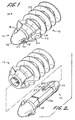
FIG.1 is a perspective view of a self-tapping two part suture screw; -
FIG.2 is a perspective view of the two part suture screw with parts separated; -
FIG.3 is another perspective view of the two part suture screw with parts separated; -
FIG. 4 is a rear perspective view of a first embodiment of the assembled sleeve component and pin component of the suture screw; -
FIG.5 is a side view, partially shown in section, of the pin component taken along line 55 ofFIG. 3 ; -
FIG. 6 is a side view, partially shown in section, taken along line 6-6 ofFIG. 3 ; -
FIG.7 is a perspective view of the two part suture screw being assembled with lengths of suture; -
FIG. 8 is a perspective view similar toFIG. 7 with tension on the sutures; -
FIG. 9 is a side view of the assembled two part suture screw being inserted in a pilot hole in bone; -
FIG. 10 is a side view of the suture screw fully seated in the bone; -
FIG. 11 is a side view of the suture being passed back through tissue; -
FIG.12 is a side view similar toFIG. 11 with the suture tensioned; -
FIG. 13 is a side view of the suture screw and suture tied to anchor and the tissue to the bone; -
FIG. 14 is a perspective view of the suture screw and an insertion tool ; -
FIG. 15 is a rear end view of a second embodiment of the sleeve component of the suture screw; and -
FIG. 16 is a perspective view of a self-tapping suture screw with a third embodiment of a sleeve component. - The examples of the device and methods disclosed herein are applicable to a wide variety of procedures including, but not limited to, tissue to bone fastening, ligament repair, joint repair or replacement, non-union fractures, facial reconstruction, etc. In addition, it is believed that the present device finds application in both open and minimally invasive procedures wherein access to the surgical site is achieved through a cannula or small incision.
- In the description which follows, the term "proximal", as is traditional, will refer to the portion of the device or structure which is closest to the operator or user, while the term "distal" refers to the portion which is further from the user.
- A two part suture screw for anchoring tissue and bone is disclosed. The suture screw includes a threaded outer sleeve having a longitudinal bore extending therethrough. Preferably a distal end of the sleeve threads are interrupted to form cutting edges making the suture screw self-tapping. The longitudinal bore has a hexagonal shape and includes a countersunk portion at its proximal end to receive an insertion tool.
- A pin having a conical insertion tip is provided and includes a proximally extending shaft configured for insertion in the longitudinal bore of the outer sleeve. An insertion tip of the pin preferably has a smooth conical surface to ease insertion in a pilot hole in bone. Proximal interrupted cutting threads may be formed on the insertion tip and mate with the interrupted threads on the sleeve. The shaft includes at least one transverse bore though the pin for slidingly receiving a length of suture.
- A pair of channels extend from the transverse bore proximally along the outer surfaces of the shaft forming half a suture receiving channel. The sleeve is provided with corresponding channels which extend proximally from a point adjacent the throughbore in the pin to form a complete bore for free sliding receipt of the suture within the suture screw. The suture contemplated for use with the disclosed suture screw has a diameter smaller than that of the transverse bore and the bores formed by the channels of the pin and sleeve to allow the suture to freely slide therein.
- A method of using the suture screw to anchor tissue to bone is also disclosed and includes providing the disclosed suture screw with a length of suture slidably positioned within the throughbore and channels. The self-tapping suture screw is threaded into bone, preferably with the assistance of a pilot hole drilled in the bone. A free end of the suture is affixed to tissue and the opposite end of the suture tensioned to draw the tissue against the bone. The suture can then be tied off or passed back through the tissue and tied off to secure the tissue to bone.
- The device and method described herein is specifically configured for self-tapping into hard structure, such as bone, and slidably receiving lengths of suture material so as to draw tissue, affixed to one end of the suture material, adjacent the suture screw. Additionally, the ability to slidably receive suture material allows the addition or exchange of one type of suture material for another.
- Referring now to
FIG.1 ,suture screw 10 includes apin component 12 and asleeve component 14 extending proximally frompin component 12.Pin component 12 and/orsleeve component 14 are preferably formed of a biocompatible material. The Material may be bioabsorbable, nonbioabsorbable, an allograft or a xenograft. Suitable bioabsorbable materials include glycolide, lactide, trimethilene carbonate, dioxanone, dioxatanone, and copolymers and blends thereof. Suitable nonbioabsorbable materials include polypropylene, polyethylene, and metals.Pin component 12 has a smooth conicaldistal tip 16 and interruptedthreads 18.Interrupted threads 18 are separated by opposingfaces Faces distal tip 16 ofpin component 12 to be self-tapping with respect to hard structure such as, for example, bone. -
Sleeve component 14 also has interruptedthreads 24 at a distal end thereof which are separated by opposingfaces sleeve component 14 to be self-tapping.Sleeve component 14 also includes acontinuous thread 30 on the outer surface thereof.Thread 30 extends from a proximal end of interruptedthread 24 to a proximal end ofsleeve component 14. As shown, when assembled, interruptedthreads 18 ofpin component 12 match with the interruptedthreads 24 ofsleeve component 14. - Referring to
FIGS. 2 and3 ,pin component 12 includes anelongated shaft 32 extending proximally from a distal end oftip 16. As shown,shaft 32 is hexagonal in cross-section and includes opposed pairs ofparallel channels Channels 34a and 34b are connected by atransverse bore 38 throughshaft 32 andchannels transverse bore 40 through a different face or part ofshaft 32. Preferably transverse bores 38 and 40 are angled in a proximal/distal direction relative to the longitudinal axis of the shaft. Additionally, bores 38 and 40 are angled relative to each other.Channels suture screw 10 are freely slidable therein. While the cross section ofshaft 32 is shown to be hexagonal, other configurations of non-circular cross sections, such as, for example, oval or square, are also contemplated. The non-circular cross sections prevent rotation ofpin 12 relative tosleeve 14 during insertion into bone. -
Tip 16 ofpin component 12 has aflat face 42 at a proximal end thereof which mates flush with a similar flat face on a distal end ofsleeve component 14.Pin component 12 also has a 'chamfered or roundedproximal end 44 to prevent fraying of sutures. - Referring now to
FIG. 3 ,sleeve component 14 is shown with interruptedthreads 24 andcontinuous threads 30.Sleeve component 14 has alongitudinal throughbore 46 having a hexagonal cross section for receipt ofelongated shaft 32 ofpin component 12. When assembled, a flatdistal face 48 ofsleeve component 14 mates flush withflat face 42 ofpin component 12. - Referring now to
FIG. 4 , there is shown a rear perspective view of assembledpin component 12 andsleeve component 14.Sleeve component 14 includes opposed pairs of semicylindrical channels channels suture screw 10. Preferably, the bores so formed are of a constant diameter larger than the largest suture to be used there through.Sleeve component 14 has an enlarged countersunkhexagonal bore 54 configured to receive and mate with a driver tip of an installation tool for drivingsuture screw 10 into bone. In this embodiment, it is envisioned that the sutures running throughsuture screw 10 would pass through a hollow bore in the tip of the installation tool and out of the tool so as to be freely manipulated. - The use of
suture screw 10 to secure a tissue section adjacent a.portion of bone will now be described. The desired location on the bone to which the tissue section is to be secured is located and appropriately prepared by scraping, etc. It may be helpful to form a small diameter pilot hole into which screw 10 can be threaded. Referring toFIG. 7 ,suture screw 10 is prepared by disassemblingpin component 12 fromsleeve component 14.Sutures bores 30 and/or 40 and the sutures are positioned inchannels longitudinal throughbore 46 ofsleeve component 14 andpin component 12. - Referring to
FIG. 8 ,sleeve component 14 andpin component 12 are assembled by insertingshaft 32 intolongitudinal throughbore 46 until flat faces 42, 48 meet flush. Care should be taken to ensurechannels pin component 12 so that the sutures remain freely slidable withinsuture screw 10. - Referring to
FIG. 9 , the free ends of thesutures bore 130 ininstallation tool 140 and a hexagonal tip 150 oftool 140 is positioned in hexagonal counter bore 54 ofsleeve component 14. Proximal tension on the sutures and distal pressure onsleeve component 14 by the installation tool help maintainsuture screw 10 in its assembled state. The installation tool is then used to drivesuture screw 10 into a predrilled pilot hole B in bone A. - Referring to
FIG. 10 , as discussed above,suture screw 10 is self-tapping. When suturescrew 10 has been fully inserted in bone B,installation tool 140 is removed and one set of the free ends of sutures 100,120 are affixed to tissue C. Thereafter, the opposing free ends of the sutures not attached to tissue are tensioned or pulled through suture screw to draw the attached tissue adjacent the bone. Alternatively, additional or substitute suture material of the same or differing type may be attached to the original sutures and pulled into and throughsuture screw 10 to provide more or a different type of suture for attachment to the tissue section. Once the tissue section has been properly positioned adjacent the bone the opposing ends of sutures may be tied off adjacent the proximal end ofsuture screw 10 in known manner or otherwise securedadjacent screw 10 and the remaining excess suture material trimmed. Preferably, sutures 100,120 are reinserted through tissue C (FIG. 11 ), tensioned to draw tissue C tight (FIG.12 ) and tied off (FIG.13 ) to secure the tissue to bone A. - Referring to
FIG. 14 , there is disclosed analternative driving tool 170 for use withsuture screw 10,tool 170 includes aproximal shaft 172 and a distalhexagonal driving head 174 to fit in countersunk bore 54 ofsleeve component 12. Cutouts 176a, 176b and 178a, 178b are provided for suture clearance. - Referring now to
FIG. 15 , there is shown an alternative sleeve component 56 having interrupted threads (not shown) separated by faces (not shown) andcontinuous thread 64 along a proximal section thereof similar to that ofsleeve component 14. Sleeve component 56 also has a hexagonallongitudinal bore 66 which extends completely through sleeve component 56. In contrast tosleeve component 14, sleeve component 56 does not have a countersunk bore and includes channels 68a, 68b and 70a, 70b which extend completely along the inner surface ofbore 66. Similar to that ofsleeve component 14, channels 68a, 68b and 70a, 70b cooperate with the corresponding channels inpin component 12 to form bores for sliding receipt of sutures. It is envisioned that the installation tool used with sleeve component 56 would have a corresponding hexagonal shaped driving tip for driving insertion inbore 66. To allow sutures to remain slidable, it would be necessary to form complementary channels in the outer surface of the installation tool tip. - Referring now to
FIG. 16 , there is disclosed an alternative embodiment of an assembledsuture screw 72.Suture screw 72 utilizespin component 12 but has an alternative embodiment of asleeve component 74.Sleeve component 74 has similar outer surface characteristics as previously described sleeve components but has a proximal hexagonal shapedprojection 76 for engagement withdriver tool 160. As shown,suture channels 78 etc. extend along the outer surface ofprojection 76 for free receipt of sutures positioned therein. - Alternatively, a modified pin component having an elongated proximally extending shaft, having suture channels, could be assembled with a corresponding sleeve component such that the proximal end of the shaft extends proximally out of the proximal end of the sleeve component.
- It will be understood that various modifications may be made to the embodiments disclosed herein. For example, the threads of the pin and/or sleeve component may be partially or completely threaded or continuous. Additionally, there may be provided only a single pair of channels and accompanying through bore or many complementary pairs greater than the two disclosed. As discussed, the connecting and driving hexagonal bores may be substituted by bores of other cross sections as well as providing corresponding substitute driving tools. The above description should not be construed as limiting, but merely as exemplifications of preferred embodiments and methods. Those skilled in the art will envision other modifications and uses within the scope of the claims appended hereto.
Claims (14)
- A suture screw (10) comprising:a sleeve (14) having a threaded (24,30) outer surface and a longitudinal bore (46,66); anda pin (12) having a tip (16) and a shaft (32) extending proximally from the tip, the shaft having at least one transverse bore (38, 40) extending from a first side of the shaft to a second side of the shaft for receiving a suture (100,120) to be freely slidable therethrough, whereinthe shaft is configured to be positionable within the longitudinal bore of the sleeve,characterised in that the tip has interrupted threads (18) formed in an outer surface thereof.
- The suture screw as recited in Claim 1 wherein the pin (12) has channels (34a,34b,36a,36b) in the first and second sides of the shaft (32) extending from the transverse bore (38,40) along the first and second sides to a proximal end (44) of the shaft.
- The suture screw as recited in Claim 2 wherein the sleeve (14) has channels (50a,50b,52a,52b) formed on an inner surface of the longitudinal bore (46,66) which extend in complementary fashion with the channels (34a,34b,36a,36b) in the shaft (32) of the pin (12).
- The suture screw of any preceding claim, wherein the shaft (32) is configured to be positionable within the longitudinal bore (46, 66) of the sleeve (14) with a suture (110,120) threaded through said transverse bore, with the free ends of the suture extending proximally of said transverse bore, thereby to assemble said suture screw so that said suture remains freely slidable within the suture screw.
- The suture screw, as recited in any preceding claim, wherein:the longitudinal bore (46) of the sleeve (14) has a predetermined cross-sectional shape; andthe shaft (32) of the pin (12) has a cross-sectional shape similar to the cross-sectional shape of the longitudinal bore (46,66) such that, when the shaft is inserted into the longitudinal bore, there is minimal rotation between the pin (12) and the sleeve (14).
- The suture screw as recited in Claim 5 wherein the shaft (32) has a hexagonal cross-section and the longitudinal bore (46,66) of the sleeve has a hexagonal cross-section to receive the shaft such that the shaft (32) cannot rotate within the sleeve (24).
- The suture screw as recited in any preceding claim, wherein the threaded surface (24) of the sleeve is interrupted at the distal end of the sleeve.
- The suture screw as recited in any preceding claim, as dependent directly or indirectly from Claim 3, further comprising a length of suture (110,120) having a diameter less than that of the transverse bore (38, 40) and being positioned through the transverse bore and within the channels (34a,34b,36a,36b) of the shaft and the channels (50a,50b,52a,52b) of the sleeve such that the suture is freely slidable therethrough.
- The suture screw as recited in any preceding claim, wherein the threads (18) of the tip (16) of the pin (12) are interrupted by cutting surfaces (20,22) which allow the tip of the pin to be self-tapping with respect to hard structure such as bone.
- The suture screw as recited in any preceding claim, wherein when said suture screw is assembled, a proximal face (42) of pin (12) mates with a distal face (48) of sleeve (14) to prevent further proximal retraction of the pin (12) relative to the sleeve (14).
- The suture screw as recited in any preceding claim, wherein the at least one transverse bore includes a first bore (38) and a second bore (40) longitudinally spaced from the first bore, and wherein the first bore and the second bore are non-intersecting.
- The suture screw as recited in any preceding claim in combination with an installation tool (140,170) for installing the suture screw, wherein said tool has a driving head (150,174) having an external cross section configured to fit in a countersunk bore (54) or a proximal portion of longitudinal bore (66) of said sleeve (14) for driving said sleeve.
- The suture screw as recited in Claim 12, wherein the installation tool includes a bore (130) or cutouts (176a,176b,178a,178b) in said driving head (150,174) to allow proximal tension to be applied to sutures assembled with said suture screw as said suture screw (10) is driven by the installation tool.
- The suture screw as recited in any one of Claims 1 to 10 in combination with an installation tool (160) for installing the suture screw, wherein said tool has a driving head for engagement with a proximal projection (76) at the proximal end of said sleeve (14), or with a proximally extending end of said shaft (32) of pin (12), for driving said sleeve by said projection (76) or by said proximally extending end of shaft (32).
Priority Applications (1)
| Application Number | Priority Date | Filing Date | Title |
|---|---|---|---|
| EP09155592A EP2070481B1 (en) | 2000-12-22 | 2001-12-22 | Suture screw |
Applications Claiming Priority (3)
| Application Number | Priority Date | Filing Date | Title |
|---|---|---|---|
| US25781300P | 2000-12-22 | 2000-12-22 | |
| US257813P | 2000-12-22 | ||
| PCT/US2001/050281 WO2002051325A2 (en) | 2000-12-22 | 2001-12-22 | Suture screw |
Related Child Applications (1)
| Application Number | Title | Priority Date | Filing Date |
|---|---|---|---|
| EP09155592A Division EP2070481B1 (en) | 2000-12-22 | 2001-12-22 | Suture screw |
Publications (2)
| Publication Number | Publication Date |
|---|---|
| EP1345546A2 EP1345546A2 (en) | 2003-09-24 |
| EP1345546B1 true EP1345546B1 (en) | 2009-03-25 |
Family
ID=22977856
Family Applications (2)
| Application Number | Title | Priority Date | Filing Date |
|---|---|---|---|
| EP09155592A Expired - Lifetime EP2070481B1 (en) | 2000-12-22 | 2001-12-22 | Suture screw |
| EP01985134A Expired - Lifetime EP1345546B1 (en) | 2000-12-22 | 2001-12-22 | Suture screw |
Family Applications Before (1)
| Application Number | Title | Priority Date | Filing Date |
|---|---|---|---|
| EP09155592A Expired - Lifetime EP2070481B1 (en) | 2000-12-22 | 2001-12-22 | Suture screw |
Country Status (7)
| Country | Link |
|---|---|
| US (2) | US6840953B2 (en) |
| EP (2) | EP2070481B1 (en) |
| AU (1) | AU2002234112B2 (en) |
| CA (1) | CA2432216C (en) |
| DE (1) | DE60138135D1 (en) |
| ES (2) | ES2378608T3 (en) |
| WO (1) | WO2002051325A2 (en) |
Cited By (1)
| Publication number | Priority date | Publication date | Assignee | Title |
|---|---|---|---|---|
| CN106137288A (en) * | 2016-07-19 | 2016-11-23 | 上海交通大学医学院附属第九人民医院 | A kind of magnesium-base metal band line holdfast and implanted device thereof |
Families Citing this family (194)
| Publication number | Priority date | Publication date | Assignee | Title |
|---|---|---|---|---|
| ATE324072T1 (en) | 1998-12-30 | 2006-05-15 | Ethicon Inc | THREAD SECURING DEVICE |
| US8343186B2 (en) * | 2004-04-06 | 2013-01-01 | Arthrex, Inc. | Fully threaded suture anchor with transverse anchor pin |
| US9521999B2 (en) | 2005-09-13 | 2016-12-20 | Arthrex, Inc. | Fully-threaded bioabsorbable suture anchor |
| US6319252B1 (en) | 1999-07-23 | 2001-11-20 | Mcdevitt Dennis | System and method for attaching soft tissue to bone |
| US6527794B1 (en) | 1999-08-10 | 2003-03-04 | Ethicon, Inc. | Self-locking suture anchor |
| US7153312B1 (en) | 1999-12-02 | 2006-12-26 | Smith & Nephew Inc. | Closure device and method for tissue repair |
| US7887551B2 (en) | 1999-12-02 | 2011-02-15 | Smith & Nephew, Inc. | Soft tissue attachment and repair |
| US7993369B2 (en) | 2000-06-22 | 2011-08-09 | Arthrex, Inc. | Graft fixation using a plug against suture |
| US6994725B1 (en) * | 2000-10-03 | 2006-02-07 | Medicinelodge, Inc. | Method and apparatus for reconstructing a ligament |
| US6733506B1 (en) | 2000-11-16 | 2004-05-11 | Ethicon, Inc. | Apparatus and method for attaching soft tissue to bone |
| US20100312292A1 (en) * | 2001-10-18 | 2010-12-09 | Orthoip, Llc | Lagwire system and method for the fixation of bone fractures |
| US20100268285A1 (en) * | 2001-10-18 | 2010-10-21 | Orthoip, Llc | Bone screw system and method for the fixation of bone fractures |
| US8702768B2 (en) | 2001-10-18 | 2014-04-22 | Orthoip, Llc | Cannulated bone screw system and method |
| US8679167B2 (en) | 2001-10-18 | 2014-03-25 | Orthoip, Llc | System and method for a cap used in the fixation of bone fractures |
| US6736819B2 (en) | 2001-10-18 | 2004-05-18 | Kishore Tipirneni | System and method for fixation of bone fractures |
| US9060809B2 (en) | 2001-10-18 | 2015-06-23 | Orthoip, Llc | Lagwire system and method for the fixation of bone fractures |
| US20080147126A1 (en) * | 2001-10-18 | 2008-06-19 | Fxdevices, Llc | System and method for a cap used in the fixation of bone fractures |
| US20090306718A1 (en) * | 2001-10-18 | 2009-12-10 | Orthoip, Llc | Filament and cap systems and methods for the fixation of bone fractures |
| US8828067B2 (en) | 2001-10-18 | 2014-09-09 | Orthoip, Llc | Bone screw system and method |
| US6685728B2 (en) * | 2002-01-25 | 2004-02-03 | Stryker Endoscopy | Threaded suture anchor and method of use |
| ES2363454T3 (en) | 2002-06-11 | 2011-08-04 | Tyco Healthcare Group Lp | MALE TIGHTS FOR HERNIAS. |
| US7517357B2 (en) * | 2003-01-09 | 2009-04-14 | Linvatec Biomaterials | Knotless suture anchor |
| US9314235B2 (en) * | 2003-02-05 | 2016-04-19 | Smith & Nephew, Inc. | Tissue anchor and insertion tool |
| CA2527778C (en) | 2003-06-13 | 2011-11-08 | Tyco Healthcare Group Lp | Multiple member interconnect for surgical instrument and absorbable screw fastener |
| US7713285B1 (en) | 2003-07-02 | 2010-05-11 | Biomet Sports Medicine, Llc | Method and apparatus for suture anchors with a vertical eyelet |
| US7780701B1 (en) | 2003-08-13 | 2010-08-24 | Biomet Sports Medicine, Llc | Suture anchor |
| US7331982B1 (en) | 2003-09-08 | 2008-02-19 | Biomet Sports Medicine, Inc. | Suture anchor and associated method |
| US7481832B1 (en) * | 2003-09-09 | 2009-01-27 | Biomet Sports Medicine, Llc | Method and apparatus for use of a self-tapping resorbable screw |
| US7837710B2 (en) * | 2003-09-10 | 2010-11-23 | Linvatec Corporation | Knotless suture anchor |
| US8016865B2 (en) | 2003-09-29 | 2011-09-13 | Depuy Mitek, Inc. | Method of performing anterior cruciate ligament reconstruction using biodegradable interference screw |
| US7608092B1 (en) | 2004-02-20 | 2009-10-27 | Biomet Sports Medicince, LLC | Method and apparatus for performing meniscus repair |
| US7645293B2 (en) | 2004-04-21 | 2010-01-12 | United States Surgical Corporation | Suture anchor installation system and method |
| US7819898B2 (en) | 2004-06-09 | 2010-10-26 | Biomet Sports Medicine, Llc | Method and apparatus for soft tissue fixation |
| US8109965B2 (en) | 2004-06-09 | 2012-02-07 | Biomet Sports Medicine, LLP | Method and apparatus for soft tissue fixation |
| US7500983B1 (en) | 2004-06-09 | 2009-03-10 | Biomet Sports Medicine, Llc | Apparatus for soft tissue attachment |
| US7695503B1 (en) * | 2004-06-09 | 2010-04-13 | Biomet Sports Medicine, Llc | Method and apparatus for soft tissue attachment |
| US7322978B2 (en) * | 2004-06-22 | 2008-01-29 | Hs West Investments, Llc | Bone anchors for use in attaching soft tissue to a bone |
| US8114127B2 (en) * | 2004-06-22 | 2012-02-14 | Hs West Investments, Llc | Bone anchors for use in attaching soft tissue to bone |
| US7914538B2 (en) * | 2004-06-28 | 2011-03-29 | Depuy Mitek, Inc. | Suture anchor inserter |
| US20180228621A1 (en) | 2004-08-09 | 2018-08-16 | Mark A. Reiley | Apparatus, systems, and methods for the fixation or fusion of bone |
| US7857830B2 (en) | 2006-02-03 | 2010-12-28 | Biomet Sports Medicine, Llc | Soft tissue repair and conduit device |
| US7905903B2 (en) | 2006-02-03 | 2011-03-15 | Biomet Sports Medicine, Llc | Method for tissue fixation |
| US8088130B2 (en) | 2006-02-03 | 2012-01-03 | Biomet Sports Medicine, Llc | Method and apparatus for coupling soft tissue to a bone |
| US8137382B2 (en) | 2004-11-05 | 2012-03-20 | Biomet Sports Medicine, Llc | Method and apparatus for coupling anatomical features |
| US7601165B2 (en) * | 2006-09-29 | 2009-10-13 | Biomet Sports Medicine, Llc | Method and apparatus for forming a self-locking adjustable suture loop |
| US7749250B2 (en) | 2006-02-03 | 2010-07-06 | Biomet Sports Medicine, Llc | Soft tissue repair assembly and associated method |
| US8128658B2 (en) | 2004-11-05 | 2012-03-06 | Biomet Sports Medicine, Llc | Method and apparatus for coupling soft tissue to bone |
| US8361113B2 (en) | 2006-02-03 | 2013-01-29 | Biomet Sports Medicine, Llc | Method and apparatus for coupling soft tissue to a bone |
| US9017381B2 (en) | 2007-04-10 | 2015-04-28 | Biomet Sports Medicine, Llc | Adjustable knotless loops |
| US7905904B2 (en) | 2006-02-03 | 2011-03-15 | Biomet Sports Medicine, Llc | Soft tissue repair device and associated methods |
| US8303604B2 (en) | 2004-11-05 | 2012-11-06 | Biomet Sports Medicine, Llc | Soft tissue repair device and method |
| US7909851B2 (en) | 2006-02-03 | 2011-03-22 | Biomet Sports Medicine, Llc | Soft tissue repair device and associated methods |
| US9801708B2 (en) | 2004-11-05 | 2017-10-31 | Biomet Sports Medicine, Llc | Method and apparatus for coupling soft tissue to a bone |
| US8840645B2 (en) | 2004-11-05 | 2014-09-23 | Biomet Sports Medicine, Llc | Method and apparatus for coupling soft tissue to a bone |
| US20060189993A1 (en) | 2004-11-09 | 2006-08-24 | Arthrotek, Inc. | Soft tissue conduit device |
| US8298262B2 (en) | 2006-02-03 | 2012-10-30 | Biomet Sports Medicine, Llc | Method for tissue fixation |
| US8118836B2 (en) | 2004-11-05 | 2012-02-21 | Biomet Sports Medicine, Llc | Method and apparatus for coupling soft tissue to a bone |
| US8998949B2 (en) | 2004-11-09 | 2015-04-07 | Biomet Sports Medicine, Llc | Soft tissue conduit device |
| US8986345B2 (en) | 2004-12-07 | 2015-03-24 | Biomet Sports Medicine, Llc | Expanding suture anchor having an actuator pin |
| JP2008535544A (en) * | 2005-03-10 | 2008-09-04 | タイコ ヘルスケア グループ リミテッド パートナーシップ | Suture anchor |
| US11801043B2 (en) | 2005-03-30 | 2023-10-31 | Arthrex, Inc. | Suture anchor for knotless fixation of tissue |
| US20080208253A1 (en) | 2006-05-18 | 2008-08-28 | Dreyfuss Peter J | Self-punching swivel anchor and method for knotless fixation of tissue |
| US20090187216A1 (en) | 2006-05-18 | 2009-07-23 | Arthrex, Inc. | Fenestrated swivel anchor for knotless fixation of tissue |
| DE602006019016D1 (en) * | 2005-03-30 | 2011-02-03 | Arthrex Inc | High-strength chain-like seam with loops for knotless attachment |
| US7862585B2 (en) * | 2005-06-23 | 2011-01-04 | Johnson & Johnson | Tissue repair device and fabrication thereof |
| US20060293675A1 (en) * | 2005-06-23 | 2006-12-28 | Zhigang Li | Tissue repair device and fabrication thereof |
| US20060293709A1 (en) | 2005-06-24 | 2006-12-28 | Bojarski Raymond A | Tissue repair device |
| EP1762186B1 (en) * | 2005-09-12 | 2011-02-16 | Arthrex, Inc. | Suture anchor with eyelet |
| GB0524360D0 (en) * | 2005-11-30 | 2006-01-04 | Biocomposites Ltd | Suture anchor |
| US7695495B2 (en) * | 2005-12-13 | 2010-04-13 | Arthrex, Inc. | Peek threaded suture anchor |
| US8323338B2 (en) * | 2005-12-22 | 2012-12-04 | Smith & Nephew, Inc. | Tissue graft fixation |
| EP2465473B1 (en) * | 2005-12-22 | 2014-06-25 | Hugh S. West Jr. | Bone anchors having thread design optimized for fixation in cortical and cancellous bone tissues |
| US8968364B2 (en) * | 2006-02-03 | 2015-03-03 | Biomet Sports Medicine, Llc | Method and apparatus for fixation of an ACL graft |
| US7959650B2 (en) | 2006-09-29 | 2011-06-14 | Biomet Sports Medicine, Llc | Adjustable knotless loops |
| US8562645B2 (en) | 2006-09-29 | 2013-10-22 | Biomet Sports Medicine, Llc | Method and apparatus for forming a self-locking adjustable loop |
| US8771352B2 (en) | 2011-05-17 | 2014-07-08 | Biomet Sports Medicine, Llc | Method and apparatus for tibial fixation of an ACL graft |
| US9271713B2 (en) | 2006-02-03 | 2016-03-01 | Biomet Sports Medicine, Llc | Method and apparatus for tensioning a suture |
| US11311287B2 (en) | 2006-02-03 | 2022-04-26 | Biomet Sports Medicine, Llc | Method for tissue fixation |
| US8251998B2 (en) | 2006-08-16 | 2012-08-28 | Biomet Sports Medicine, Llc | Chondral defect repair |
| US9078644B2 (en) | 2006-09-29 | 2015-07-14 | Biomet Sports Medicine, Llc | Fracture fixation device |
| US10517587B2 (en) | 2006-02-03 | 2019-12-31 | Biomet Sports Medicine, Llc | Method and apparatus for forming a self-locking adjustable loop |
| US8562647B2 (en) | 2006-09-29 | 2013-10-22 | Biomet Sports Medicine, Llc | Method and apparatus for securing soft tissue to bone |
| US9149267B2 (en) | 2006-02-03 | 2015-10-06 | Biomet Sports Medicine, Llc | Method and apparatus for coupling soft tissue to a bone |
| US8574235B2 (en) | 2006-02-03 | 2013-11-05 | Biomet Sports Medicine, Llc | Method for trochanteric reattachment |
| US9538998B2 (en) | 2006-02-03 | 2017-01-10 | Biomet Sports Medicine, Llc | Method and apparatus for fracture fixation |
| US8801783B2 (en) | 2006-09-29 | 2014-08-12 | Biomet Sports Medicine, Llc | Prosthetic ligament system for knee joint |
| US11259792B2 (en) | 2006-02-03 | 2022-03-01 | Biomet Sports Medicine, Llc | Method and apparatus for coupling anatomical features |
| US8506597B2 (en) | 2011-10-25 | 2013-08-13 | Biomet Sports Medicine, Llc | Method and apparatus for interosseous membrane reconstruction |
| US8597327B2 (en) | 2006-02-03 | 2013-12-03 | Biomet Manufacturing, Llc | Method and apparatus for sternal closure |
| US8936621B2 (en) | 2006-02-03 | 2015-01-20 | Biomet Sports Medicine, Llc | Method and apparatus for forming a self-locking adjustable loop |
| US8652172B2 (en) | 2006-02-03 | 2014-02-18 | Biomet Sports Medicine, Llc | Flexible anchors for tissue fixation |
| US8652171B2 (en) | 2006-02-03 | 2014-02-18 | Biomet Sports Medicine, Llc | Method and apparatus for soft tissue fixation |
| US20070213730A1 (en) * | 2006-03-09 | 2007-09-13 | Jonathan Martinek | Cannulated suture anchor system |
| US20070219558A1 (en) * | 2006-03-15 | 2007-09-20 | Allen Deutsch | Method and apparatus for arthroscopic surgery using suture anchors |
| US20080009904A1 (en) * | 2006-03-17 | 2008-01-10 | Bourque Barnard J | Soft Tissue Fixation |
| US20070219557A1 (en) * | 2006-03-17 | 2007-09-20 | Bourque Bernard J | Soft tissue fixation |
| EP1836996A1 (en) * | 2006-03-20 | 2007-09-26 | Inion Oy | Implant for securing a flexible piece to bone |
| US7828820B2 (en) * | 2006-03-21 | 2010-11-09 | Biomet Sports Medicine, Llc | Method and apparatuses for securing suture |
| AU2007202269B2 (en) | 2006-05-18 | 2013-01-24 | Arthrex, Inc. | Swivel anchor and method for knotless fixation of tissue |
| AU2007275351B2 (en) * | 2006-07-20 | 2013-10-24 | Lee D. Kaplan | Surgical instruments |
| US8202295B2 (en) | 2006-07-20 | 2012-06-19 | Kaplan Lee D | Surgical instruments |
| US9788825B2 (en) | 2006-08-04 | 2017-10-17 | Depuy Mitek, Llc | Suture anchor with relief mechanism |
| US9750492B2 (en) | 2006-08-04 | 2017-09-05 | Depuy Mitek, Llc | Suture anchor system with tension relief mechanism |
| US20080033487A1 (en) * | 2006-08-07 | 2008-02-07 | Bioduct, Llc | Medical device for repair of tissue and method for implantation and fixation |
| US11259794B2 (en) | 2006-09-29 | 2022-03-01 | Biomet Sports Medicine, Llc | Method for implanting soft tissue |
| US8672969B2 (en) | 2006-09-29 | 2014-03-18 | Biomet Sports Medicine, Llc | Fracture fixation device |
| US9918826B2 (en) | 2006-09-29 | 2018-03-20 | Biomet Sports Medicine, Llc | Scaffold for spring ligament repair |
| US8500818B2 (en) | 2006-09-29 | 2013-08-06 | Biomet Manufacturing, Llc | Knee prosthesis assembly with ligament link |
| US8083769B2 (en) | 2006-11-01 | 2011-12-27 | Depuy Mitek, Inc. | Wired sutures |
| US20080109037A1 (en) * | 2006-11-03 | 2008-05-08 | Musculoskeletal Transplant Foundation | Press fit suture anchor and inserter assembly |
| US20080167660A1 (en) * | 2007-01-04 | 2008-07-10 | Nathan Ryan Moreau | Suture anchor and inserter arrangement |
| WO2008134504A1 (en) * | 2007-04-25 | 2008-11-06 | Alaska Hand Research, Llc | Method and device for stabilizing joints with limited axial movement |
| US7794484B2 (en) | 2007-05-07 | 2010-09-14 | Biomet Sports Medicine, Llc | Fixation device for delivery of biological material between soft tissue and bone |
| EP2150183B1 (en) * | 2007-05-31 | 2013-03-20 | Cook Medical Technologies LLC | Suture lock |
| US8882801B2 (en) * | 2007-09-14 | 2014-11-11 | Depuy Mitek, Llc | Dual thread cannulated suture anchor |
| US8702754B2 (en) | 2007-09-14 | 2014-04-22 | Depuy Mitek, Llc | Methods for anchoring suture to bone |
| US8632568B2 (en) * | 2007-09-24 | 2014-01-21 | Stryker Corporation | Suture anchor having a suture engaging structure and inserter arrangement |
| US8197511B2 (en) * | 2007-09-24 | 2012-06-12 | Miller M Todd | Suture anchor having a suture engaging structure and inserter arrangement |
| US9072509B2 (en) * | 2007-10-12 | 2015-07-07 | Howmedica Osteonics Corp. | Toggle bolt suture anchor kit |
| WO2009055800A1 (en) | 2007-10-25 | 2009-04-30 | Smith & Nephew, Inc. | Anchor assembly |
| EP2214565A4 (en) * | 2007-10-27 | 2015-08-26 | Parcus Medical Llc | Suture anchor |
| WO2014189605A1 (en) | 2013-03-15 | 2014-11-27 | Mark Brunsvold | Suture anchor |
| US8454654B2 (en) * | 2007-12-13 | 2013-06-04 | Smith & Nephew, Inc. | Anchoring system |
| WO2009114316A2 (en) * | 2008-03-03 | 2009-09-17 | Alaska Hand Research, Llc | Cannulated anchor and system |
| US8162978B2 (en) * | 2008-03-25 | 2012-04-24 | Linvatec Corporation | Non-metallic knotless suture anchor |
| EP2323588A1 (en) * | 2008-05-14 | 2011-05-25 | Smith & Nephew, Inc. | Arthroscopic biceps tenodesis repair |
| CN102098968B (en) | 2008-07-17 | 2015-07-22 | 史密夫和内修有限公司 | Anchor |
| CN102098969B (en) | 2008-07-17 | 2013-07-17 | 史密夫和内修有限公司 | Surgical devices |
| US20100049249A1 (en) * | 2008-08-25 | 2010-02-25 | Linvatec Corporation | Suture anchor extension |
| US8790368B2 (en) * | 2008-09-18 | 2014-07-29 | Smith & Nephew, Inc. | Tenodesis implant |
| US8858606B2 (en) | 2008-12-09 | 2014-10-14 | Smith & Nephew, Inc. | Tissue repair assembly |
| JP5904794B2 (en) | 2008-12-09 | 2016-04-20 | スミス アンド ネフュー インコーポレーテッドSmith & Nephew,Inc. | Tissue repair assembly |
| AU2009327446B2 (en) | 2008-12-15 | 2015-10-15 | Smith & Nephew, Inc. | Composite anchor |
| US8523902B2 (en) | 2009-01-30 | 2013-09-03 | Kfx Medical Corporation | System and method for attaching soft tissue to bone |
| WO2010115072A1 (en) | 2009-04-03 | 2010-10-07 | Wilson-Cook Medical, Inc. | Tissue anchors and medical devices for rapid deployment of tissue anchors |
| AU2010232485B2 (en) * | 2009-04-03 | 2013-11-07 | Cook Medical Technologies Llc | Medical devices, systems, and methods for rapid deployment and fixation of tissue anchors |
| US8343227B2 (en) | 2009-05-28 | 2013-01-01 | Biomet Manufacturing Corp. | Knee prosthesis assembly with ligament link |
| ES2908450T3 (en) * | 2009-10-13 | 2022-04-29 | Conmed Corp | System to fix tissue to bone |
| AU2010315413B2 (en) * | 2009-10-28 | 2016-02-18 | Smith & Nephew, Inc. | Threaded suture anchor |
| US8613756B2 (en) | 2009-10-30 | 2013-12-24 | Depuy Mitek, Llc | Knotless suture anchor |
| CN102711632B (en) | 2009-11-10 | 2015-11-25 | 史密夫和内修有限公司 | Tissue repair apparatus |
| US20120083841A1 (en) * | 2010-09-30 | 2012-04-05 | Depuy Mitek, Inc. | Suture anchor with suture management |
| US9044313B2 (en) | 2010-10-08 | 2015-06-02 | Kfx Medical Corporation | System and method for securing tissue to bone |
| EP2637577B1 (en) * | 2010-11-09 | 2017-10-18 | Cook Medical Technologies LLC | Clip system having tether segments for closure |
| US9713463B2 (en) * | 2011-01-13 | 2017-07-25 | Howmedica Osteonics Corp | Toggle bolt assembly and method of assembly |
| BR112013024058A2 (en) * | 2011-03-22 | 2016-12-13 | Smith & Nephew Inc | anchor system and shipping device for your use |
| ES2873024T3 (en) | 2011-04-13 | 2021-11-03 | Conmed Corp | Tissue-to-bone fixation system |
| EP3791797A1 (en) | 2011-10-04 | 2021-03-17 | ConMed Corporation | Dual expansion anchor |
| US9357991B2 (en) | 2011-11-03 | 2016-06-07 | Biomet Sports Medicine, Llc | Method and apparatus for stitching tendons |
| US9370350B2 (en) | 2011-11-10 | 2016-06-21 | Biomet Sports Medicine, Llc | Apparatus for coupling soft tissue to a bone |
| US9381013B2 (en) | 2011-11-10 | 2016-07-05 | Biomet Sports Medicine, Llc | Method for coupling soft tissue to a bone |
| US9357992B2 (en) | 2011-11-10 | 2016-06-07 | Biomet Sports Medicine, Llc | Method for coupling soft tissue to a bone |
| EP2775937B1 (en) * | 2011-11-11 | 2016-07-20 | Venture MD | Transosseous attachment anchor |
| US9782165B2 (en) | 2011-11-11 | 2017-10-10 | VentureMD Innovations, LLC | Transosseous attachment |
| US10548585B2 (en) | 2011-11-16 | 2020-02-04 | VentureMD Innovations, LLC | Soft tissue attachment |
| US10136883B2 (en) | 2011-11-16 | 2018-11-27 | VentureMD Innovations, LLC | Method of anchoring a suture |
| US10470756B2 (en) | 2011-11-16 | 2019-11-12 | VentureMD Innovations, LLC | Suture anchor and method |
| US10675014B2 (en) | 2011-11-16 | 2020-06-09 | Crossroads Extremity Systems, Llc | Knotless soft tissue attachment |
| US9259217B2 (en) | 2012-01-03 | 2016-02-16 | Biomet Manufacturing, Llc | Suture Button |
| US10363140B2 (en) | 2012-03-09 | 2019-07-30 | Si-Bone Inc. | Systems, device, and methods for joint fusion |
| CN104334102A (en) | 2012-03-09 | 2015-02-04 | 西-博恩公司 | Integrated implant |
| US8858596B2 (en) | 2012-03-20 | 2014-10-14 | Stryker Corporation | Suture anchor having a suture engaging structure |
| EP2846705B1 (en) | 2012-05-04 | 2018-12-26 | SI-Bone, Inc. | Fenestrated implant |
| US9687221B2 (en) | 2013-02-13 | 2017-06-27 | Venture MD Innovations, LLC | Method of anchoring a suture |
| JP6382237B2 (en) | 2013-03-06 | 2018-08-29 | スミス アンド ネフュー インコーポレーテッドSmith & Nephew,Inc. | Micro anchor |
| US9757119B2 (en) | 2013-03-08 | 2017-09-12 | Biomet Sports Medicine, Llc | Visual aid for identifying suture limbs arthroscopically |
| ES2959496T3 (en) | 2013-03-14 | 2024-02-26 | Conmed Corp | Tissue Capture Bone Anchor |
| US9918827B2 (en) | 2013-03-14 | 2018-03-20 | Biomet Sports Medicine, Llc | Scaffold for spring ligament repair |
| BR112015022461B1 (en) | 2013-03-15 | 2021-11-23 | Conmed Corporation | EXPANDABLE BONE ANCHOR |
| US9572563B2 (en) | 2013-07-08 | 2017-02-21 | Biomet Sports Medicine, LLC. | Suture anchor and related method |
| US10136886B2 (en) | 2013-12-20 | 2018-11-27 | Biomet Sports Medicine, Llc | Knotless soft tissue devices and techniques |
| EP3113690B1 (en) * | 2014-03-06 | 2022-01-05 | Smith & Nephew, Inc. | Two-piece knotless suture anchor |
| US9615822B2 (en) | 2014-05-30 | 2017-04-11 | Biomet Sports Medicine, Llc | Insertion tools and method for soft anchor |
| US9700291B2 (en) | 2014-06-03 | 2017-07-11 | Biomet Sports Medicine, Llc | Capsule retractor |
| US10039543B2 (en) | 2014-08-22 | 2018-08-07 | Biomet Sports Medicine, Llc | Non-sliding soft anchor |
| US10166033B2 (en) | 2014-09-18 | 2019-01-01 | Si-Bone Inc. | Implants for bone fixation or fusion |
| WO2016044053A1 (en) | 2014-09-19 | 2016-03-24 | Crossroads Extremity Systems, Llc | Bone fixation implant and means of fixation |
| US10575883B2 (en) | 2014-12-15 | 2020-03-03 | Smith & Nephew, Inc. | Active fracture compression implants |
| US9955980B2 (en) | 2015-02-24 | 2018-05-01 | Biomet Sports Medicine, Llc | Anatomic soft tissue repair |
| US9974534B2 (en) | 2015-03-31 | 2018-05-22 | Biomet Sports Medicine, Llc | Suture anchor with soft anchor of electrospun fibers |
| US9924935B2 (en) | 2015-10-23 | 2018-03-27 | Smith & Nephew, Inc. | Suture anchor assembly with slip fit tip |
| CA2995787A1 (en) * | 2017-02-22 | 2018-08-22 | Stryker Corporation | Fixation member with separate eyelet and methods of use thereof |
| US10893933B2 (en) | 2017-02-24 | 2021-01-19 | James Jastifer | Tissue anchors, kits, and associated methods |
| AU2018310776B2 (en) | 2017-08-03 | 2021-07-01 | 9384-4934 Québec Inc. | Plug for bone tissue |
| WO2019067584A1 (en) | 2017-09-26 | 2019-04-04 | Si-Bone Inc. | Systems and methods for decorticating the sacroiliac joint |
| WO2019217970A1 (en) * | 2018-05-11 | 2019-11-14 | Dunamis, LLC | Knotless anchor assembly and methods thereof |
| US11369419B2 (en) | 2019-02-14 | 2022-06-28 | Si-Bone Inc. | Implants for spinal fixation and or fusion |
| EP3923829A4 (en) | 2019-02-14 | 2022-12-14 | SI-Bone, Inc. | Implants for spinal fixation and or fusion |
| WO2021108590A1 (en) | 2019-11-27 | 2021-06-03 | Si-Bone, Inc. | Bone stabilizing implants and methods of placement across si joints |
| US11723647B2 (en) * | 2019-12-17 | 2023-08-15 | Globus Medical, Inc. | Syndesmosis fixation assembly |
| DE212021000375U1 (en) * | 2020-05-08 | 2023-03-01 | Lifespans Limited | Bone fixation system and elements thereof |
| CA3183696A1 (en) * | 2020-06-02 | 2021-12-09 | Conmed Corporation | Self-punching lateral row anchor and anchor driver |
| JP2023553120A (en) | 2020-12-09 | 2023-12-20 | エスアイ-ボーン・インコーポレイテッド | Sacroiliac joint stabilization implants and implant methods |
| CN113425350B (en) * | 2021-05-13 | 2023-03-17 | 花沐医疗科技(上海)有限公司 | Composite absorbable suture anchor and preparation method thereof |
Family Cites Families (75)
| Publication number | Priority date | Publication date | Assignee | Title |
|---|---|---|---|---|
| US4259072A (en) * | 1977-04-04 | 1981-03-31 | Kyoto Ceramic Co., Ltd. | Ceramic endosseous implant |
| US4454875A (en) | 1982-04-15 | 1984-06-19 | Techmedica, Inc. | Osteal medical staple |
| US4570623A (en) | 1983-06-02 | 1986-02-18 | Pfizer Hospital Products Group Inc. | Arched bridge staple |
| US4738255A (en) | 1986-04-07 | 1988-04-19 | Biotron Labs, Inc. | Suture anchor system |
| US4895148A (en) * | 1986-05-20 | 1990-01-23 | Concept, Inc. | Method of joining torn parts of bodily tissue in vivo with a biodegradable tack member |
| US4772286A (en) * | 1987-02-17 | 1988-09-20 | E. Marlowe Goble | Ligament attachment method and apparatus |
| USRE34293F1 (en) * | 1987-02-17 | 1998-04-07 | Globe Marlowe E | Ligament attachment method and apparatus |
| US4870957A (en) * | 1988-12-27 | 1989-10-03 | Marlowe Goble E | Ligament anchor system |
| US4950270A (en) * | 1989-02-03 | 1990-08-21 | Boehringer Mannheim Corporation | Cannulated self-tapping bone screw |
| US4927421A (en) * | 1989-05-15 | 1990-05-22 | Marlowe Goble E | Process of endosteal fixation of a ligament |
| US5019080A (en) * | 1990-02-13 | 1991-05-28 | Trextron Inc. | Drive system for prosthetic fasteners |
| US5013316A (en) | 1990-03-26 | 1991-05-07 | Marlowe Goble E | Soft tissue anchor system |
| US5100417A (en) * | 1990-07-13 | 1992-03-31 | American Cyanamid Company | Suture anchor and driver assembly |
| US5258016A (en) * | 1990-07-13 | 1993-11-02 | American Cyanamid Company | Suture anchor and driver assembly |
| EP0547134B1 (en) | 1990-09-04 | 1997-10-15 | Hip Developments Pty. Ltd. | Surgical screw |
| US5725529A (en) * | 1990-09-25 | 1998-03-10 | Innovasive Devices, Inc. | Bone fastener |
| US5122133A (en) * | 1990-10-26 | 1992-06-16 | Smith & Nephew Richards Inc. | Compression screw for a joint endoprosthesis |
| US5320115A (en) * | 1991-01-16 | 1994-06-14 | Applied Biological Concepts | Method and apparatus for arthroscopic knee surgery |
| US5354298A (en) * | 1991-03-22 | 1994-10-11 | United States Surgical Corporation | Suture anchor installation system |
| US5480403A (en) * | 1991-03-22 | 1996-01-02 | United States Surgical Corporation | Suture anchoring device and method |
| CA2073266A1 (en) * | 1991-07-09 | 1993-01-10 | Mehmet Rona | Distal targeting system |
| US5258001A (en) | 1991-09-05 | 1993-11-02 | Baylor College Of Medicine | Retractable scalpel with blade-activated lock |
| US5156616A (en) * | 1992-02-10 | 1992-10-20 | Meadows Bruce F | Apparatus and method for suture attachment |
| US5425733A (en) * | 1992-02-19 | 1995-06-20 | Arthrex, Inc. | Interference screw with rounded back end and cannulated sheath for endosteal fixation of ligaments |
| US5176682A (en) | 1992-06-01 | 1993-01-05 | Chow James C Y | Surgical implement |
| GB9212732D0 (en) * | 1992-06-16 | 1992-07-29 | Amp Gmbh | Sealed electrical connector and method of making the same |
| US5354299A (en) * | 1992-12-07 | 1994-10-11 | Linvatec Corporation | Method of revising a screw in a tunnel |
| US5443509A (en) * | 1992-12-10 | 1995-08-22 | Linvatec Corporation | Interference bone-fixation screw with multiple interleaved threads |
| US5372599A (en) | 1993-03-12 | 1994-12-13 | Mitek Surgical Products, Inc. | Surgical anchor and method for deploying the same |
| US5824011A (en) | 1993-06-23 | 1998-10-20 | Kevin R. Stone | Suture anchor assembly |
| US5370662A (en) * | 1993-06-23 | 1994-12-06 | Kevin R. Stone | Suture anchor assembly |
| US5540718A (en) | 1993-09-20 | 1996-07-30 | Bartlett; Edwin C. | Apparatus and method for anchoring sutures |
| US5584835A (en) * | 1993-10-18 | 1996-12-17 | Greenfield; Jon B. | Soft tissue to bone fixation device and method |
| US5456685A (en) * | 1994-02-14 | 1995-10-10 | Smith & Nephew Dyonics, Inc. | Interference screw having a tapered back root |
| US5417712A (en) | 1994-02-17 | 1995-05-23 | Mitek Surgical Products, Inc. | Bone anchor |
| US5573548A (en) * | 1994-06-09 | 1996-11-12 | Zimmer, Inc. | Suture anchor |
| US5472452A (en) | 1994-08-30 | 1995-12-05 | Linvatec Corporation | Rectilinear anchor for soft tissue fixation |
| US5522845A (en) * | 1994-09-27 | 1996-06-04 | Mitek Surgical Products, Inc. | Bone anchor and bone anchor installation |
| US6235057B1 (en) * | 1995-01-24 | 2001-05-22 | Smith & Nephew, Inc. | Method for soft tissue reconstruction |
| US5603716A (en) * | 1995-02-16 | 1997-02-18 | Arthrex Inc. | Method of ligament reconstruction using double socket graft placement and fixation |
| US5571139A (en) * | 1995-05-19 | 1996-11-05 | Jenkins, Jr.; Joseph R. | Bidirectional suture anchor |
| US5904704A (en) | 1995-08-14 | 1999-05-18 | Mitek Surgical Products, Inc. | Suture anchor assembly |
| BR9707531A (en) * | 1996-02-16 | 1999-07-27 | Smith & Nephew Inc | graft anchor |
| US5702397A (en) | 1996-02-20 | 1997-12-30 | Medicinelodge, Inc. | Ligament bone anchor and method for its use |
| US5690672A (en) * | 1996-06-12 | 1997-11-25 | Dignity Wear, Ltd. | Tourniquet apparatus with replaceable cover |
| FR2750595B1 (en) | 1996-07-02 | 1998-12-04 | Dev Sed Soc Et | MEDICAL SCREWS ESPECIALLY FOR SURGERY AND ANCILLARY OF POSITION |
| US5951559A (en) * | 1996-07-25 | 1999-09-14 | Arthrex, Inc. | Method for installing a threaded suture anchor with a cannulated suture anchor drill guide |
| US6117162A (en) * | 1996-08-05 | 2000-09-12 | Arthrex, Inc. | Corkscrew suture anchor |
| US5733307A (en) | 1996-09-17 | 1998-03-31 | Amei Technologies, Inc. | Bone anchor having a suture trough |
| US5948000A (en) | 1996-10-03 | 1999-09-07 | United States Surgical Corporation | System for suture anchor placement |
| US5948001A (en) * | 1996-10-03 | 1999-09-07 | United States Surgical Corporation | System for suture anchor placement |
| US6436124B1 (en) * | 1996-12-19 | 2002-08-20 | Bionx Implants Oy | Suture anchor |
| US5918604A (en) * | 1997-02-12 | 1999-07-06 | Arthrex, Inc. | Method of loading tendons into the knee |
| US5782866A (en) | 1997-03-25 | 1998-07-21 | Ethicon, Inc. | System for anchoring tissue to bone |
| US5884294A (en) * | 1997-04-18 | 1999-03-16 | Northrop Grumman Corporation | System and method for functional recognition of emitters |
| US5899921A (en) * | 1997-07-25 | 1999-05-04 | Innovasive Devices, Inc. | Connector device and method for surgically joining and securing flexible tissue repair members |
| US6010525A (en) * | 1997-08-01 | 2000-01-04 | Peter M. Bonutti | Method and apparatus for securing a suture |
| US5871504A (en) * | 1997-10-21 | 1999-02-16 | Eaton; Katulle Koco | Anchor assembly and method for securing ligaments to bone |
| US5944724A (en) * | 1997-10-30 | 1999-08-31 | Mitek Surgical Products, Inc. | Suture anchor insertion system |
| US6149669A (en) | 1997-10-30 | 2000-11-21 | Li Medical Technologies, Inc. | Surgical fastener assembly method of use |
| US6387129B2 (en) * | 1998-03-18 | 2002-05-14 | Arthrex, Inc. | Bicortical tibial fixation of ACL grafts |
| US6436100B1 (en) * | 1998-08-07 | 2002-08-20 | J. Lee Berger | Cannulated internally threaded bone screw and reduction driver device |
| US6146407A (en) * | 1998-09-11 | 2000-11-14 | Bio Innovation, Ltd. | Suture anchor installation devices and methods |
| US6045573A (en) * | 1999-01-21 | 2000-04-04 | Ethicon, Inc. | Suture anchor having multiple sutures |
| US6096060A (en) | 1999-05-20 | 2000-08-01 | Linvatec Corporation | Bioabsorbable threaded soft tissue anchor system |
| US6517542B1 (en) * | 1999-08-04 | 2003-02-11 | The Cleveland Clinic Foundation | Bone anchoring system |
| US6592609B1 (en) * | 1999-08-09 | 2003-07-15 | Bonutti 2003 Trust-A | Method and apparatus for securing tissue |
| US6527794B1 (en) * | 1999-08-10 | 2003-03-04 | Ethicon, Inc. | Self-locking suture anchor |
| EP1101459B1 (en) * | 1999-11-15 | 2006-02-22 | Arthrex, Inc. | Tapered bioabsorbable interference screw for endosteal fixation of ligaments |
| US6461373B2 (en) * | 2000-05-26 | 2002-10-08 | Arthrex, Inc. | Biointerference screw fixation technique |
| US6666877B2 (en) * | 2000-09-12 | 2003-12-23 | Axya Medical, Inc. | Apparatus and method for securing suture to bone |
| US6692516B2 (en) * | 2000-11-28 | 2004-02-17 | Linvatec Corporation | Knotless suture anchor and method for knotlessly securing tissue |
| US6508830B2 (en) * | 2001-04-30 | 2003-01-21 | Musculoskeletal Transplant Foundation | Suture anchor |
| US6652563B2 (en) * | 2001-10-02 | 2003-11-25 | Arthrex, Inc. | Suture anchor with internal suture loop |
| US20030125749A1 (en) * | 2001-12-27 | 2003-07-03 | Ethicon, Inc. | Cannulated screw and associated driver system |
-
2001
- 2001-12-22 US US10/033,951 patent/US6840953B2/en not_active Expired - Fee Related
- 2001-12-22 ES ES09155592T patent/ES2378608T3/en not_active Expired - Lifetime
- 2001-12-22 EP EP09155592A patent/EP2070481B1/en not_active Expired - Lifetime
- 2001-12-22 CA CA002432216A patent/CA2432216C/en not_active Expired - Fee Related
- 2001-12-22 EP EP01985134A patent/EP1345546B1/en not_active Expired - Lifetime
- 2001-12-22 WO PCT/US2001/050281 patent/WO2002051325A2/en not_active Application Discontinuation
- 2001-12-22 ES ES01985134T patent/ES2325612T3/en not_active Expired - Lifetime
- 2001-12-22 DE DE60138135T patent/DE60138135D1/en not_active Expired - Lifetime
- 2001-12-22 AU AU2002234112A patent/AU2002234112B2/en not_active Ceased
-
2005
- 2005-01-06 US US11/030,633 patent/US20050119698A1/en not_active Abandoned
Cited By (2)
| Publication number | Priority date | Publication date | Assignee | Title |
|---|---|---|---|---|
| CN106137288A (en) * | 2016-07-19 | 2016-11-23 | 上海交通大学医学院附属第九人民医院 | A kind of magnesium-base metal band line holdfast and implanted device thereof |
| CN106137288B (en) * | 2016-07-19 | 2019-11-19 | 上海交通大学医学院附属第九人民医院 | A kind of magnesium-base metal band line holdfast and its implanted device |
Also Published As
| Publication number | Publication date |
|---|---|
| US6840953B2 (en) | 2005-01-11 |
| DE60138135D1 (en) | 2009-05-07 |
| AU2002234112B2 (en) | 2006-12-14 |
| WO2002051325A2 (en) | 2002-07-04 |
| EP2070481A1 (en) | 2009-06-17 |
| EP2070481B1 (en) | 2012-02-08 |
| EP1345546A2 (en) | 2003-09-24 |
| CA2432216A1 (en) | 2002-07-04 |
| ES2325612T3 (en) | 2009-09-10 |
| US20050119698A1 (en) | 2005-06-02 |
| CA2432216C (en) | 2009-03-10 |
| US20020147463A1 (en) | 2002-10-10 |
| ES2378608T3 (en) | 2012-04-16 |
| WO2002051325A3 (en) | 2002-12-12 |
Similar Documents
| Publication | Publication Date | Title |
|---|---|---|
| EP1345546B1 (en) | Suture screw | |
| AU2002234112A1 (en) | Suture screw | |
| US11576664B2 (en) | Methods for anchoring suture to bone | |
| AU2018203826B2 (en) | Self-cinching suture anchors, systems and methods | |
| US20200315775A1 (en) | Fixation Member With Separate Eyelet And Methods Of Use Thereof | |
| EP1530951B1 (en) | Suture loop anchor | |
| EP2036501B1 (en) | Dual Thread Cannulated Suture Anchor | |
| US6673094B1 (en) | System and method for attaching soft tissue to bone | |
| US20020115999A1 (en) | System and method for attaching soft tissue to bone | |
| US20080109037A1 (en) | Press fit suture anchor and inserter assembly |
Legal Events
| Date | Code | Title | Description |
|---|---|---|---|
| PUAI | Public reference made under article 153(3) epc to a published international application that has entered the european phase |
Free format text: ORIGINAL CODE: 0009012 |
|
| 17P | Request for examination filed |
Effective date: 20030715 |
|
| AK | Designated contracting states |
Kind code of ref document: A2 Designated state(s): AT BE CH CY DE DK ES FI FR GB GR IE IT LI LU MC NL PT SE TR |
|
| AX | Request for extension of the european patent |
Extension state: AL LT LV MK RO SI |
|
| RBV | Designated contracting states (corrected) |
Designated state(s): AT BE CH CY DE ES FR GB IT LI |
|
| 17Q | First examination report despatched |
Effective date: 20061228 |
|
| GRAP | Despatch of communication of intention to grant a patent |
Free format text: ORIGINAL CODE: EPIDOSNIGR1 |
|
| GRAP | Despatch of communication of intention to grant a patent |
Free format text: ORIGINAL CODE: EPIDOSNIGR1 |
|
| RIC1 | Information provided on ipc code assigned before grant |
Ipc: A61B 17/04 20060101AFI20081008BHEP |
|
| RBV | Designated contracting states (corrected) |
Designated state(s): DE ES FR GB IT |
|
| GRAS | Grant fee paid |
Free format text: ORIGINAL CODE: EPIDOSNIGR3 |
|
| GRAA | (expected) grant |
Free format text: ORIGINAL CODE: 0009210 |
|
| AK | Designated contracting states |
Kind code of ref document: B1 Designated state(s): DE ES FR GB IT |
|
| REG | Reference to a national code |
Ref country code: GB Ref legal event code: FG4D |
|
| REF | Corresponds to: |
Ref document number: 60138135 Country of ref document: DE Date of ref document: 20090507 Kind code of ref document: P |
|
| REG | Reference to a national code |
Ref country code: ES Ref legal event code: FG2A Ref document number: 2325612 Country of ref document: ES Kind code of ref document: T3 |
|
| REG | Reference to a national code |
Ref country code: GB Ref legal event code: 732E Free format text: REGISTERED BETWEEN 20090827 AND 20090902 |
|
| RAP2 | Party data changed (patent owner data changed or rights of a patent transferred) |
Owner name: TYCO HEALTHCARE GROUP LP |
|
| PLBE | No opposition filed within time limit |
Free format text: ORIGINAL CODE: 0009261 |
|
| STAA | Information on the status of an ep patent application or granted ep patent |
Free format text: STATUS: NO OPPOSITION FILED WITHIN TIME LIMIT |
|
| 26N | No opposition filed |
Effective date: 20091229 |
|
| PGFP | Annual fee paid to national office [announced via postgrant information from national office to epo] |
Ref country code: IT Payment date: 20101223 Year of fee payment: 10 |
|
| PGFP | Annual fee paid to national office [announced via postgrant information from national office to epo] |
Ref country code: ES Payment date: 20111226 Year of fee payment: 11 |
|
| PGFP | Annual fee paid to national office [announced via postgrant information from national office to epo] |
Ref country code: GB Payment date: 20121227 Year of fee payment: 12 |
|
| PGFP | Annual fee paid to national office [announced via postgrant information from national office to epo] |
Ref country code: FR Payment date: 20130110 Year of fee payment: 12 |
|
| PGFP | Annual fee paid to national office [announced via postgrant information from national office to epo] |
Ref country code: DE Payment date: 20121231 Year of fee payment: 12 |
|
| PG25 | Lapsed in a contracting state [announced via postgrant information from national office to epo] |
Ref country code: IT Free format text: LAPSE BECAUSE OF NON-PAYMENT OF DUE FEES Effective date: 20121222 |
|
| REG | Reference to a national code |
Ref country code: ES Ref legal event code: FD2A Effective date: 20140307 |
|
| PG25 | Lapsed in a contracting state [announced via postgrant information from national office to epo] |
Ref country code: ES Free format text: LAPSE BECAUSE OF NON-PAYMENT OF DUE FEES Effective date: 20121223 |
|
| REG | Reference to a national code |
Ref country code: DE Ref legal event code: R119 Ref document number: 60138135 Country of ref document: DE |
|
| GBPC | Gb: european patent ceased through non-payment of renewal fee |
Effective date: 20131222 |
|
| REG | Reference to a national code |
Ref country code: DE Ref legal event code: R119 Ref document number: 60138135 Country of ref document: DE Effective date: 20140701 |
|
| REG | Reference to a national code |
Ref country code: FR Ref legal event code: ST Effective date: 20140829 |
|
| PG25 | Lapsed in a contracting state [announced via postgrant information from national office to epo] |
Ref country code: DE Free format text: LAPSE BECAUSE OF NON-PAYMENT OF DUE FEES Effective date: 20140701 |
|
| PG25 | Lapsed in a contracting state [announced via postgrant information from national office to epo] |
Ref country code: GB Free format text: LAPSE BECAUSE OF NON-PAYMENT OF DUE FEES Effective date: 20131222 Ref country code: FR Free format text: LAPSE BECAUSE OF NON-PAYMENT OF DUE FEES Effective date: 20131231 |