EP1342479A1 - Assembly for controlling and regulating flow of a dialysis solution in a haemodiafiltration process - Google Patents
Assembly for controlling and regulating flow of a dialysis solution in a haemodiafiltration process Download PDFInfo
- Publication number
- EP1342479A1 EP1342479A1 EP03005118A EP03005118A EP1342479A1 EP 1342479 A1 EP1342479 A1 EP 1342479A1 EP 03005118 A EP03005118 A EP 03005118A EP 03005118 A EP03005118 A EP 03005118A EP 1342479 A1 EP1342479 A1 EP 1342479A1
- Authority
- EP
- European Patent Office
- Prior art keywords
- dialysis solution
- filter
- assembly
- blood
- flow
- Prior art date
- Legal status (The legal status is an assumption and is not a legal conclusion. Google has not performed a legal analysis and makes no representation as to the accuracy of the status listed.)
- Granted
Links
Images

Classifications
-
- A—HUMAN NECESSITIES
- A61—MEDICAL OR VETERINARY SCIENCE; HYGIENE
- A61M—DEVICES FOR INTRODUCING MEDIA INTO, OR ONTO, THE BODY; DEVICES FOR TRANSDUCING BODY MEDIA OR FOR TAKING MEDIA FROM THE BODY; DEVICES FOR PRODUCING OR ENDING SLEEP OR STUPOR
- A61M1/00—Suction or pumping devices for medical purposes; Devices for carrying-off, for treatment of, or for carrying-over, body-liquids; Drainage systems
- A61M1/14—Dialysis systems; Artificial kidneys; Blood oxygenators ; Reciprocating systems for treatment of body fluids, e.g. single needle systems for hemofiltration or pheresis
- A61M1/16—Dialysis systems; Artificial kidneys; Blood oxygenators ; Reciprocating systems for treatment of body fluids, e.g. single needle systems for hemofiltration or pheresis with membranes
- A61M1/1601—Control or regulation
- A61M1/1603—Regulation parameters
- A61M1/1605—Physical characteristics of the dialysate fluid
-
- A—HUMAN NECESSITIES
- A61—MEDICAL OR VETERINARY SCIENCE; HYGIENE
- A61M—DEVICES FOR INTRODUCING MEDIA INTO, OR ONTO, THE BODY; DEVICES FOR TRANSDUCING BODY MEDIA OR FOR TAKING MEDIA FROM THE BODY; DEVICES FOR PRODUCING OR ENDING SLEEP OR STUPOR
- A61M1/00—Suction or pumping devices for medical purposes; Devices for carrying-off, for treatment of, or for carrying-over, body-liquids; Drainage systems
- A61M1/14—Dialysis systems; Artificial kidneys; Blood oxygenators ; Reciprocating systems for treatment of body fluids, e.g. single needle systems for hemofiltration or pheresis
- A61M1/16—Dialysis systems; Artificial kidneys; Blood oxygenators ; Reciprocating systems for treatment of body fluids, e.g. single needle systems for hemofiltration or pheresis with membranes
- A61M1/1601—Control or regulation
- A61M1/1617—Control or regulation using measurements made during a temporary variation of a characteristic of the fresh dialysis fluid
-
- A—HUMAN NECESSITIES
- A61—MEDICAL OR VETERINARY SCIENCE; HYGIENE
- A61M—DEVICES FOR INTRODUCING MEDIA INTO, OR ONTO, THE BODY; DEVICES FOR TRANSDUCING BODY MEDIA OR FOR TAKING MEDIA FROM THE BODY; DEVICES FOR PRODUCING OR ENDING SLEEP OR STUPOR
- A61M1/00—Suction or pumping devices for medical purposes; Devices for carrying-off, for treatment of, or for carrying-over, body-liquids; Drainage systems
- A61M1/14—Dialysis systems; Artificial kidneys; Blood oxygenators ; Reciprocating systems for treatment of body fluids, e.g. single needle systems for hemofiltration or pheresis
- A61M1/16—Dialysis systems; Artificial kidneys; Blood oxygenators ; Reciprocating systems for treatment of body fluids, e.g. single needle systems for hemofiltration or pheresis with membranes
- A61M1/1694—Dialysis systems; Artificial kidneys; Blood oxygenators ; Reciprocating systems for treatment of body fluids, e.g. single needle systems for hemofiltration or pheresis with membranes with recirculating dialysing liquid
- A61M1/1696—Dialysis systems; Artificial kidneys; Blood oxygenators ; Reciprocating systems for treatment of body fluids, e.g. single needle systems for hemofiltration or pheresis with membranes with recirculating dialysing liquid with dialysate regeneration
-
- A—HUMAN NECESSITIES
- A61—MEDICAL OR VETERINARY SCIENCE; HYGIENE
- A61M—DEVICES FOR INTRODUCING MEDIA INTO, OR ONTO, THE BODY; DEVICES FOR TRANSDUCING BODY MEDIA OR FOR TAKING MEDIA FROM THE BODY; DEVICES FOR PRODUCING OR ENDING SLEEP OR STUPOR
- A61M1/00—Suction or pumping devices for medical purposes; Devices for carrying-off, for treatment of, or for carrying-over, body-liquids; Drainage systems
- A61M1/34—Filtering material out of the blood by passing it through a membrane, i.e. hemofiltration or diafiltration
- A61M1/3413—Diafiltration
-
- A—HUMAN NECESSITIES
- A61—MEDICAL OR VETERINARY SCIENCE; HYGIENE
- A61M—DEVICES FOR INTRODUCING MEDIA INTO, OR ONTO, THE BODY; DEVICES FOR TRANSDUCING BODY MEDIA OR FOR TAKING MEDIA FROM THE BODY; DEVICES FOR PRODUCING OR ENDING SLEEP OR STUPOR
- A61M2205/00—General characteristics of the apparatus
- A61M2205/33—Controlling, regulating or measuring
- A61M2205/3306—Optical measuring means
-
- A—HUMAN NECESSITIES
- A61—MEDICAL OR VETERINARY SCIENCE; HYGIENE
- A61M—DEVICES FOR INTRODUCING MEDIA INTO, OR ONTO, THE BODY; DEVICES FOR TRANSDUCING BODY MEDIA OR FOR TAKING MEDIA FROM THE BODY; DEVICES FOR PRODUCING OR ENDING SLEEP OR STUPOR
- A61M2205/00—General characteristics of the apparatus
- A61M2205/33—Controlling, regulating or measuring
- A61M2205/3331—Pressure; Flow
- A61M2205/3334—Measuring or controlling the flow rate
Definitions
- the present invention relates to an assembly for controlling and regulating flow of a dialysis solution in a haemodiafiltration process.
- Dialysis is a blood purifying process whereby toxic substances accumulated in the organism as a result of kidney failure are eliminated by transfer to a fluid with an electrolytic content similar to that of normal plasma containing no toxic substances, and which here and hereinafter is referred to as a "dialysis solution".
- the blood and dialysis solution are brought into contact in a filtering member comprising a semipermeable membrane. More specifically, the blood is circulated on one side of the membrane, and the dialysis solution is circulated in the opposite flow direction on the other side. That is, when drawn from the patient's arm, the blood flows along the so-called artery line into the dialysis filter, in which the dialysis solution circulates in the opposite direction and, by diffusion through the membrane, withdraws surplus toxic substances from the blood; and the purified blood issuing from the filter is restored to the patient along the so-called vein line.
- the blood is also purified by convection.
- Convection occurs whenever a pressure gradient is produced between the dialysis solution compartment and the blood compartment and in favour of the latter, so that plasma water flows through the semipermeable membrane, taking with it the toxic substances dissolved in it.
- a large amount of plasma water must be filtered, which means reinfusing a salt solution into the blood to maintain a suitable water balance.
- the dialysis solution circuit is normally regulated by a first and second pumping system upstream and downstream from the filter respectively, and reinfusion is performed along the vein line using a third pumping system which reinfuses a solution similar to the dialysis solution into the blood to restore the blood to its original volume minus the required weight loss.
- a major drawback of machines with the above equipment lies in failure of the first and second pumping systems to provide for both accurately regulating the dialysis solution, and accurate reinfusion calculated also as a function of the weight loss.
- the need for a third pumping system also has obvious drawbacks in terms of maintenance, size, and the limited extent to which the equipment can be used for more complex treatment.
- an assembly for controlling and regulating flow of a dialysis solution in a haemodiafiltration process comprising at least a first pump and a second pump located respectively along a dialysis solution inlet branch and outlet branch of a haemodialysis filter; said assembly being characterized by comprising differential reading means for reading the difference in flow of the dialysis solution in and out of said filter; and a central control unit for receiving information from said differential reading means, and making a calculated variation in the delivery of one of said pumps, so as to periodically regulate the pressure of the dialysis solution in said filter, and impose alternate calculated flow, through a membrane of the filter, of both the dialysis solution and the plasma water in the blood for purification.
- the central control unit acts on a pump located along the dialysis solution outlet branch of the filter.
- the assembly according to the present invention and as defined above provides for accurately reading and regulating the pressure of the dialysis solution in the haemodialysis filter, and so causing accurate, calculated convection of both the plasma water towards' the dialysis solution compartment, and of the dialysis solution towards the blood compartment.
- the amount of reinfusion into the blood is therefore calculated accurately by working on the pressure of the dialysis solution in the filter, while at the same time releasing one pump for use in other types of dialysis treatment.
- Number 1 in Figure 1 indicates as a whole a known dialysis machine (shown only partly), of which are shown schematically a haemodialysis filter 2 comprising a semipermeable membrane 3 dividing filter 2 into a dialysis solution compartment 2a and a blood compartment 2b; an artery line 4 for feeding blood into filter 2; a vein line 5 for feeding blood from filter 2 to the patient; and the assembly 6 for controlling and regulating dialysis solution flow according to the present invention.
- Assembly 6 comprises an inlet branch 7 and an outlet branch 8 for feeding the dialysis solution to and from filter 2 respectively; a differential flowmeter 9 employing the Coriolis principle (known and therefore not described in detail) and involving portions of inlet branch 7 and outlet branch 8; and a central control unit 10 for receiving information from differential flowmeter 9 and accordingly operating (in known manner) a pumping system 11 acting on outlet branch 8.
- a second pumping system 17 controlling dialysis solution flow to compartment 2a of filter 2
- regulating outflow by regulating the delivery of pumping system 11 it is possible to regulate the pressure of the dialysis solution in compartment 2a of filter 2, and so regulate the amount and direction of fluid flowing by convection through membrane 3.
- central control unit 10 operates pumping system 11 to produce, inside filter 2, a calculated, periodic gradient inversion of the pressure in compartment 2a and the pressure in compartment 2b, and so produce a calculated, periodic flow of dialysis solution or plasma water through membrane 3.
- the weight loss determined by the specific requirements of the patient must be taken into account.
- Assembly 6 also comprises a detector 12 located along dialysis solution outlet branch 8 to detect any damage to semipermeable membrane 3, by detecting the presence or absence of traces of haemoglobin along dialysis solution outlet branch 8 of filter 2. Since dialysis is compromised by any damage to semipermeable membrane 3, the membrane must be constantly monitored, and the entire filter 2 replaced if necessary.
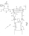
- Figure 2 shows an assembly in accordance with the present invention applied to a combined haemodiafiltration-haemolipodialysis system, and any parts of which similar to those described with reference to Figure 1 are indicated using the same numbering system with no further description.
- Artery line 4 is fitted with a haemolipodialysis filter 13, which produces purified blood using liposomes, which are brought into contact with the blood via a membrane in filter 13 as described in the Applicant's Patent Application EP 0966980.
- the combination described herein employs a peristaltic pump 15, which may advantageously be the one forming part of the known reinfusion system and made redundant by replacing the system with the assembly according to the present invention.
- the assembly according to the present invention ensures reinfusion of a precise quantity of dialysis solution into the blood, while at the same time eliminating a pump and the dialysis solution circuit of which the pump forms part.
- the pump made redundant by the assembly according to the invention may be put to other uses to enhance the efficiency of the dialysis operation as a whole.
- Differential flowmeter 9 provides for determining the difference in flow in and out of filter 2 and vice versa, i.e. for determining extremely accurately the amount of fluid flowing from compartment 2a to compartment 2b, and vice versa.
Abstract
Description
- The present invention relates to an assembly for controlling and regulating flow of a dialysis solution in a haemodiafiltration process.
- Dialysis is a blood purifying process whereby toxic substances accumulated in the organism as a result of kidney failure are eliminated by transfer to a fluid with an electrolytic content similar to that of normal plasma containing no toxic substances, and which here and hereinafter is referred to as a "dialysis solution".
- In conventional haemodialysis, the blood and dialysis solution are brought into contact in a filtering member comprising a semipermeable membrane. More specifically, the blood is circulated on one side of the membrane, and the dialysis solution is circulated in the opposite flow direction on the other side. That is, when drawn from the patient's arm, the blood flows along the so-called artery line into the dialysis filter, in which the dialysis solution circulates in the opposite direction and, by diffusion through the membrane, withdraws surplus toxic substances from the blood; and the purified blood issuing from the filter is restored to the patient along the so-called vein line.
- In the haemodiafiltration process to which the invention refers, in addition to diffusion, by balancing the concentrations of two solutions brought into contact as described above, the blood is also purified by convection. Convection occurs whenever a pressure gradient is produced between the dialysis solution compartment and the blood compartment and in favour of the latter, so that plasma water flows through the semipermeable membrane, taking with it the toxic substances dissolved in it. For convection to be effective in terms of blood purification, a large amount of plasma water must be filtered, which means reinfusing a salt solution into the blood to maintain a suitable water balance. By the end of dialysis, however, a certain amount of fluid that the kidneys are no longer capable of eliminating in urine has been withdrawn from the patient, and which, known as "weight loss", must be taken into account when reinfusing the salt solution into the blood.
- In haemodiafiltration, the dialysis solution circuit is normally regulated by a first and second pumping system upstream and downstream from the filter respectively, and reinfusion is performed along the vein line using a third pumping system which reinfuses a solution similar to the dialysis solution into the blood to restore the blood to its original volume minus the required weight loss.
- A major drawback of machines with the above equipment lies in failure of the first and second pumping systems to provide for both accurately regulating the dialysis solution, and accurate reinfusion calculated also as a function of the weight loss. The need for a third pumping system also has obvious drawbacks in terms of maintenance, size, and the limited extent to which the equipment can be used for more complex treatment.
- It is an object of the present invention to provide a dialysis machine designed to calculate, to an adequate degree of precision, the amount of dialysis solution reinfused into the blood, and at the same to reduce the size of the machine itself.
- According to the present invention, there is provided an assembly for controlling and regulating flow of a dialysis solution in a haemodiafiltration process, comprising at least a first pump and a second pump located respectively along a dialysis solution inlet branch and outlet branch of a haemodialysis filter; said assembly being characterized by comprising differential reading means for reading the difference in flow of the dialysis solution in and out of said filter; and a central control unit for receiving information from said differential reading means, and making a calculated variation in the delivery of one of said pumps, so as to periodically regulate the pressure of the dialysis solution in said filter, and impose alternate calculated flow, through a membrane of the filter, of both the dialysis solution and the plasma water in the blood for purification.
- In a preferred embodiment of the assembly according to the present invention, the central control unit acts on a pump located along the dialysis solution outlet branch of the filter.
- The assembly according to the present invention and as defined above provides for accurately reading and regulating the pressure of the dialysis solution in the haemodialysis filter, and so causing accurate, calculated convection of both the plasma water towards' the dialysis solution compartment, and of the dialysis solution towards the blood compartment. The amount of reinfusion into the blood is therefore calculated accurately by working on the pressure of the dialysis solution in the filter, while at the same time releasing one pump for use in other types of dialysis treatment.
- A non-limiting embodiment of the present invention will be described by way of example with reference to the accompanying drawings, in which:
- Figure 1 shows a schematic diagram of a preferred embodiment of the assembly for controlling and regulating flow of a dialysis solution in a haemodiafiltration process;
- Figure 2 shows a schematic diagram of the Figure 1 assembly applied to a combined haemodiafiltration-haemolipodialysis process.
- Number 1 in Figure 1 indicates as a whole a known dialysis machine (shown only partly), of which are shown schematically a
haemodialysis filter 2 comprising asemipermeable membrane 3 dividingfilter 2 into adialysis solution compartment 2a and ablood compartment 2b; an artery line 4 for feeding blood intofilter 2; avein line 5 for feeding blood fromfilter 2 to the patient; and theassembly 6 for controlling and regulating dialysis solution flow according to the present invention. -
Assembly 6 comprises aninlet branch 7 and anoutlet branch 8 for feeding the dialysis solution to and fromfilter 2 respectively; adifferential flowmeter 9 employing the Coriolis principle (known and therefore not described in detail) and involving portions ofinlet branch 7 andoutlet branch 8; and acentral control unit 10 for receiving information fromdifferential flowmeter 9 and accordingly operating (in known manner) apumping system 11 acting onoutlet branch 8. By maintaining a fixed delivery of asecond pumping system 17 controlling dialysis solution flow tocompartment 2a offilter 2, and by regulating outflow by regulating the delivery ofpumping system 11, it is possible to regulate the pressure of the dialysis solution incompartment 2a offilter 2, and so regulate the amount and direction of fluid flowing by convection throughmembrane 3. - In actual use,
central control unit 10 operatespumping system 11 to produce, insidefilter 2, a calculated, periodic gradient inversion of the pressure incompartment 2a and the pressure incompartment 2b, and so produce a calculated, periodic flow of dialysis solution or plasma water throughmembrane 3. Obviously, in determining the pressure gradient causing the plasma water to flow from the blood to the dialysis solution in the blood, the weight loss determined by the specific requirements of the patient must be taken into account. -
Assembly 6 also comprises adetector 12 located along dialysissolution outlet branch 8 to detect any damage tosemipermeable membrane 3, by detecting the presence or absence of traces of haemoglobin along dialysissolution outlet branch 8 offilter 2. Since dialysis is compromised by any damage tosemipermeable membrane 3, the membrane must be constantly monitored, and theentire filter 2 replaced if necessary. - Figure 2 shows an assembly in accordance with the present invention applied to a combined haemodiafiltration-haemolipodialysis system, and any parts of which similar to those described with reference to Figure 1 are indicated using the same numbering system with no further description.
- Artery line 4 is fitted with a
haemolipodialysis filter 13, which produces purified blood using liposomes, which are brought into contact with the blood via a membrane infilter 13 as described in the Applicant's Patent Application EP 0966980. - Combining haemodiafiltration and haemolipodialysis enhances the effectiveness of dialysis as a whole. The combination described herein employs a peristaltic pump 15, which may advantageously be the one forming part of the known reinfusion system and made redundant by replacing the system with the assembly according to the present invention.
- As will be obvious from the foregoing description, the assembly according to the present invention ensures reinfusion of a precise quantity of dialysis solution into the blood, while at the same time eliminating a pump and the dialysis solution circuit of which the pump forms part. Moreover, as shown in the combined haemodiafiltration-haemolipodialysis process in Figure 2, the pump made redundant by the assembly according to the invention may be put to other uses to enhance the efficiency of the dialysis operation as a whole.
-
Differential flowmeter 9 provides for determining the difference in flow in and out offilter 2 and vice versa, i.e. for determining extremely accurately the amount of fluid flowing fromcompartment 2a tocompartment 2b, and vice versa. - Clearly, changes may be made to the assembly for controlling and regulating flow of a dialysis solution in a haemodiafiltration process as described herein without, however, departing from the scope of the accompanying Claims.
Claims (7)
- An assembly (6) for controlling and regulating flow of a dialysis solution in a haemodiafiltration process, comprising at least a first pump (17) and a second pump (11) located respectively along a dialysis solution inlet branch (7) and outlet branch (8) of a haemodialysis filter (2); said assembly being characterized by comprising differential reading means (9) for reading the difference in flow of the dialysis solution in and out of said filter (2); and a central control unit (10) for receiving information from said differential reading means (9), and making a calculated variation in the delivery of one of said pumps (11, 17), so as to periodically regulate the pressure of the dialysis solution in said filter (2), and impose alternate calculated flow, through a' membrane (3) of the filter (2), of both the dialysis solution and the plasma water in the blood for purification.
- An assembly as claimed in Claim 1, characterized in that said pump (11) is located along said dialysis solution outlet branch (8) of the haemodialysis filter (2).
- An assembly as claimed in Claim 1 and/or 2, characterized in that said differential reading means (9) read both the quantity of plasma water withdrawn from the blood, and the quantity of dialysis solution fed into the blood.
- An assembly as claimed in any one of the foregoing Claims, characterized in that said differential reading means (9) are defined by a differential flowmeter (9) .
- An assembly as claimed in Claim 4, characterized in that said differential flowmeter (9) works on the Coriolis principle.
- An assembly as claimed in any one of the foregoing Claims, characterized by comprising a detector (12) located along the dialysis solution outlet branch (8) to detect the presence of haemoglobin along the dialysis solution outlet branch (8).
- An assembly as claimed in any one of the foregoing Claims, characterized by comprising a haemolipodialysis filter (13) upstream from said haemodialysis filter (2).
Applications Claiming Priority (2)
| Application Number | Priority Date | Filing Date | Title |
|---|---|---|---|
| ITBO20020119 | 2002-03-08 | ||
| IT2002BO000119A ITBO20020119A1 (en) | 2002-03-08 | 2002-03-08 | GROUP FOR THE CONTROL AND VARIATION OF THE FLOW OF A DIALIZING SOLUTION IN A HEMODIAFILTRATION PROCESS |
Publications (2)
| Publication Number | Publication Date |
|---|---|
| EP1342479A1 true EP1342479A1 (en) | 2003-09-10 |
| EP1342479B1 EP1342479B1 (en) | 2004-12-15 |
Family
ID=11439965
Family Applications (1)
| Application Number | Title | Priority Date | Filing Date |
|---|---|---|---|
| EP03005118A Expired - Lifetime EP1342479B1 (en) | 2002-03-08 | 2003-03-07 | Assembly for controlling and regulating flow of a dialysis solution in a haemodiafiltration process |
Country Status (5)
| Country | Link |
|---|---|
| EP (1) | EP1342479B1 (en) |
| AT (1) | ATE284719T1 (en) |
| DE (1) | DE60300202T2 (en) |
| ES (1) | ES2235121T3 (en) |
| IT (1) | ITBO20020119A1 (en) |
Cited By (5)
| Publication number | Priority date | Publication date | Assignee | Title |
|---|---|---|---|---|
| ITBO20110444A1 (en) * | 2011-07-26 | 2013-01-27 | Bellco Srl | DIALYSIS MACHINE WITH EMOLYSIS CONTROL |
| US8398859B2 (en) | 2007-04-23 | 2013-03-19 | Fundacion Para La Investigacion Biomedica Del Hospital Gregorio Maranon | Haemodialfiltration method and apparatus |
| US8485999B2 (en) | 2008-10-14 | 2013-07-16 | Gambro Lundia Ab | Blood treatment apparatus and method |
| EP2799097A2 (en) | 2013-05-02 | 2014-11-05 | B. Braun Avitum AG | Device for treating blood outside the body |
| WO2015121403A1 (en) * | 2014-02-17 | 2015-08-20 | Bayer Technology Services Gmbh | Ultrafiltration unit for continuous buffer or media exchange from a protein solution |
Citations (4)
| Publication number | Priority date | Publication date | Assignee | Title |
|---|---|---|---|---|
| EP0516152A1 (en) * | 1991-05-29 | 1992-12-02 | BELLCO S.p.A. | Apparatus for hemodiafiltration treatment |
| US5660722A (en) * | 1994-07-13 | 1997-08-26 | Fresenius Ag | Hemo(dia)filtration apparatus and filtrate flow regulator |
| EP0966980A2 (en) * | 1995-12-22 | 1999-12-29 | BELLCO S.p.A. | Method of rapidly removing liposoluble target molecules from a colloidal solution and wash solution for such a method |
| WO2000006217A1 (en) * | 1998-07-31 | 2000-02-10 | Althin Medical, Inc. | Methods and apparatus for performing controlled ultrafiltration during hemodialysis |
-
2002
- 2002-03-08 IT IT2002BO000119A patent/ITBO20020119A1/en unknown
-
2003
- 2003-03-07 DE DE60300202T patent/DE60300202T2/en not_active Expired - Lifetime
- 2003-03-07 ES ES03005118T patent/ES2235121T3/en not_active Expired - Lifetime
- 2003-03-07 EP EP03005118A patent/EP1342479B1/en not_active Expired - Lifetime
- 2003-03-07 AT AT03005118T patent/ATE284719T1/en active
Patent Citations (4)
| Publication number | Priority date | Publication date | Assignee | Title |
|---|---|---|---|---|
| EP0516152A1 (en) * | 1991-05-29 | 1992-12-02 | BELLCO S.p.A. | Apparatus for hemodiafiltration treatment |
| US5660722A (en) * | 1994-07-13 | 1997-08-26 | Fresenius Ag | Hemo(dia)filtration apparatus and filtrate flow regulator |
| EP0966980A2 (en) * | 1995-12-22 | 1999-12-29 | BELLCO S.p.A. | Method of rapidly removing liposoluble target molecules from a colloidal solution and wash solution for such a method |
| WO2000006217A1 (en) * | 1998-07-31 | 2000-02-10 | Althin Medical, Inc. | Methods and apparatus for performing controlled ultrafiltration during hemodialysis |
Cited By (12)
| Publication number | Priority date | Publication date | Assignee | Title |
|---|---|---|---|---|
| US8398859B2 (en) | 2007-04-23 | 2013-03-19 | Fundacion Para La Investigacion Biomedica Del Hospital Gregorio Maranon | Haemodialfiltration method and apparatus |
| US8485999B2 (en) | 2008-10-14 | 2013-07-16 | Gambro Lundia Ab | Blood treatment apparatus and method |
| US8545427B2 (en) | 2008-10-14 | 2013-10-01 | Gambro Lundia Ab | Blood treatment apparatus and method |
| ITBO20110444A1 (en) * | 2011-07-26 | 2013-01-27 | Bellco Srl | DIALYSIS MACHINE WITH EMOLYSIS CONTROL |
| EP2550987A1 (en) * | 2011-07-26 | 2013-01-30 | Bellco S.r.l. | Dialysis machine with haemolysis control |
| EP2799097A2 (en) | 2013-05-02 | 2014-11-05 | B. Braun Avitum AG | Device for treating blood outside the body |
| DE102013104501A1 (en) | 2013-05-02 | 2014-11-06 | B. Braun Avitum Ag | Device for extracorporeal blood treatment |
| US9700662B2 (en) | 2013-05-02 | 2017-07-11 | B. Braun Avitum Ag | Device for extracorporeal blood treatment |
| WO2015121403A1 (en) * | 2014-02-17 | 2015-08-20 | Bayer Technology Services Gmbh | Ultrafiltration unit for continuous buffer or media exchange from a protein solution |
| TWI632156B (en) * | 2014-02-17 | 2018-08-11 | 拜耳廠股份有限公司 | Ultrafiltration unit for continuous buffer or medium exchange from a protein solution |
| AU2015217006B2 (en) * | 2014-02-17 | 2019-09-12 | Bayer Aktiengesellschaft | Ultrafiltration unit for continuous buffer or media exchange from a protein solution |
| US10421042B2 (en) | 2014-02-17 | 2019-09-24 | Bayer Aktiengesellschaft | Ultrafiltration unit for continuous buffer or medium exchange from a protein solution |
Also Published As
| Publication number | Publication date |
|---|---|
| EP1342479B1 (en) | 2004-12-15 |
| ITBO20020119A1 (en) | 2003-09-08 |
| DE60300202T2 (en) | 2006-01-12 |
| ES2235121T3 (en) | 2005-07-01 |
| DE60300202D1 (en) | 2005-01-20 |
| ATE284719T1 (en) | 2005-01-15 |
| ITBO20020119A0 (en) | 2002-03-08 |
Similar Documents
| Publication | Publication Date | Title |
|---|---|---|
| JP4584959B2 (en) | Two-stage diafiltration method and apparatus | |
| JP4098624B2 (en) | Multistage hemodiafiltration / blood filtration method and apparatus | |
| JP5543049B2 (en) | Method of operating blood purification apparatus and blood purification apparatus | |
| EP1729836B1 (en) | Blood treatment equipment and software program for controlling infusion. | |
| AU750282B2 (en) | Methods and apparatus for performing controlled ultrafiltration during hemodialysis | |
| US6042784A (en) | Method and apparatus for ultrafiltration in hemodialysis | |
| KR101047970B1 (en) | In vitro treatment apparatus of blood for selectively extracting solutes | |
| US6280632B1 (en) | Device and method for preparation of substitution solution | |
| JPS6247366A (en) | Blood dialyzing and filtering apparatus | |
| US20040045881A1 (en) | Method and apparatus for generating a sterile infusion fluid | |
| EP2452705B1 (en) | Device for the treatment of blood with selective extraction of solutes | |
| SE9703403L (en) | Method and Device for Monitoring Infusion Pump in a Hemo or Hemodia Filtration Machine | |
| JP2003320023A (en) | Method for continuing extracorporeal blood treatment at flow speed of suspending or modifying extracorporeal blood treatment and apparatus for extracorporeal blood | |
| JP4757168B2 (en) | Method for feeding back-filtered dialysate in hemodialyzer and hemodialyzer | |
| EP1342479B1 (en) | Assembly for controlling and regulating flow of a dialysis solution in a haemodiafiltration process | |
| EP2550987B1 (en) | Dialysis machine with haemolysis control | |
| EP1779880A1 (en) | Hemodialyzer capable of intermittent repetition of infusion and water removal operation | |
| US10821216B1 (en) | Method and apparatus for a hemodiafiltration module for use with a dialysis machine | |
| CN111936179A (en) | Set of blood tubes, open-loop or closed-loop control device, blood treatment apparatus and method for single-needle treatment | |
| EP1810703B1 (en) | Dialysis machine with arterial pressure monitoring by measuring blood oxygen saturation and sodium concentration | |
| US11806458B2 (en) | Blood treatment device with automatic reduction of a substitution-solution flow rate | |
| JP6953162B2 (en) | Blood purifier | |
| JPH06134031A (en) | Blood dialyzing and filtering device | |
| CN109641096B (en) | Blood treatment device and method for operating a blood treatment device | |
| CN117838961A (en) | Blood purification device and storage medium |
Legal Events
| Date | Code | Title | Description |
|---|---|---|---|
| PUAI | Public reference made under article 153(3) epc to a published international application that has entered the european phase |
Free format text: ORIGINAL CODE: 0009012 |
|
| AK | Designated contracting states |
Kind code of ref document: A1 Designated state(s): AT BE BG CH CY CZ DE DK EE ES FI FR GB GR HU IE IT LI LU MC NL PT RO SE SI SK TR |
|
| AX | Request for extension of the european patent |
Extension state: AL LT LV MK |
|
| 17P | Request for examination filed |
Effective date: 20040308 |
|
| AKX | Designation fees paid |
Designated state(s): AT BE BG CH CY CZ DE DK EE ES FI FR GB GR HU IE IT LI LU MC NL PT RO SE SI SK TR |
|
| GRAP | Despatch of communication of intention to grant a patent |
Free format text: ORIGINAL CODE: EPIDOSNIGR1 |
|
| GRAS | Grant fee paid |
Free format text: ORIGINAL CODE: EPIDOSNIGR3 |
|
| GRAA | (expected) grant |
Free format text: ORIGINAL CODE: 0009210 |
|
| AK | Designated contracting states |
Kind code of ref document: B1 Designated state(s): AT BE BG CH CY CZ DE DK EE ES FI FR GB GR HU IE IT LI LU MC NL PT RO SE SI SK TR |
|
| PG25 | Lapsed in a contracting state [announced via postgrant information from national office to epo] |
Ref country code: LI Free format text: LAPSE BECAUSE OF FAILURE TO SUBMIT A TRANSLATION OF THE DESCRIPTION OR TO PAY THE FEE WITHIN THE PRESCRIBED TIME-LIMIT Effective date: 20041215 Ref country code: SI Free format text: LAPSE BECAUSE OF FAILURE TO SUBMIT A TRANSLATION OF THE DESCRIPTION OR TO PAY THE FEE WITHIN THE PRESCRIBED TIME-LIMIT Effective date: 20041215 Ref country code: RO Free format text: LAPSE BECAUSE OF FAILURE TO SUBMIT A TRANSLATION OF THE DESCRIPTION OR TO PAY THE FEE WITHIN THE PRESCRIBED TIME-LIMIT Effective date: 20041215 Ref country code: NL Free format text: LAPSE BECAUSE OF FAILURE TO SUBMIT A TRANSLATION OF THE DESCRIPTION OR TO PAY THE FEE WITHIN THE PRESCRIBED TIME-LIMIT Effective date: 20041215 Ref country code: FI Free format text: LAPSE BECAUSE OF FAILURE TO SUBMIT A TRANSLATION OF THE DESCRIPTION OR TO PAY THE FEE WITHIN THE PRESCRIBED TIME-LIMIT Effective date: 20041215 Ref country code: EE Free format text: LAPSE BECAUSE OF FAILURE TO SUBMIT A TRANSLATION OF THE DESCRIPTION OR TO PAY THE FEE WITHIN THE PRESCRIBED TIME-LIMIT Effective date: 20041215 Ref country code: CZ Free format text: LAPSE BECAUSE OF FAILURE TO SUBMIT A TRANSLATION OF THE DESCRIPTION OR TO PAY THE FEE WITHIN THE PRESCRIBED TIME-LIMIT Effective date: 20041215 Ref country code: BG Free format text: LAPSE BECAUSE OF FAILURE TO SUBMIT A TRANSLATION OF THE DESCRIPTION OR TO PAY THE FEE WITHIN THE PRESCRIBED TIME-LIMIT Effective date: 20041215 Ref country code: CH Free format text: LAPSE BECAUSE OF FAILURE TO SUBMIT A TRANSLATION OF THE DESCRIPTION OR TO PAY THE FEE WITHIN THE PRESCRIBED TIME-LIMIT Effective date: 20041215 Ref country code: TR Free format text: LAPSE BECAUSE OF FAILURE TO SUBMIT A TRANSLATION OF THE DESCRIPTION OR TO PAY THE FEE WITHIN THE PRESCRIBED TIME-LIMIT Effective date: 20041215 Ref country code: SK Free format text: LAPSE BECAUSE OF FAILURE TO SUBMIT A TRANSLATION OF THE DESCRIPTION OR TO PAY THE FEE WITHIN THE PRESCRIBED TIME-LIMIT Effective date: 20041215 |
|
| REG | Reference to a national code |
Ref country code: GB Ref legal event code: FG4D Ref country code: CH Ref legal event code: EP |
|
| REG | Reference to a national code |
Ref country code: IE Ref legal event code: FG4D |
|
| REF | Corresponds to: |
Ref document number: 60300202 Country of ref document: DE Date of ref document: 20050120 Kind code of ref document: P |
|
| PG25 | Lapsed in a contracting state [announced via postgrant information from national office to epo] |
Ref country code: LU Free format text: LAPSE BECAUSE OF NON-PAYMENT OF DUE FEES Effective date: 20050307 Ref country code: IE Free format text: LAPSE BECAUSE OF NON-PAYMENT OF DUE FEES Effective date: 20050307 Ref country code: CY Free format text: LAPSE BECAUSE OF FAILURE TO SUBMIT A TRANSLATION OF THE DESCRIPTION OR TO PAY THE FEE WITHIN THE PRESCRIBED TIME-LIMIT Effective date: 20050307 |
|
| PG25 | Lapsed in a contracting state [announced via postgrant information from national office to epo] |
Ref country code: DK Free format text: LAPSE BECAUSE OF FAILURE TO SUBMIT A TRANSLATION OF THE DESCRIPTION OR TO PAY THE FEE WITHIN THE PRESCRIBED TIME-LIMIT Effective date: 20050315 Ref country code: GR Free format text: LAPSE BECAUSE OF FAILURE TO SUBMIT A TRANSLATION OF THE DESCRIPTION OR TO PAY THE FEE WITHIN THE PRESCRIBED TIME-LIMIT Effective date: 20050315 Ref country code: SE Free format text: LAPSE BECAUSE OF FAILURE TO SUBMIT A TRANSLATION OF THE DESCRIPTION OR TO PAY THE FEE WITHIN THE PRESCRIBED TIME-LIMIT Effective date: 20050315 |
|
| PG25 | Lapsed in a contracting state [announced via postgrant information from national office to epo] |
Ref country code: HU Free format text: LAPSE BECAUSE OF FAILURE TO SUBMIT A TRANSLATION OF THE DESCRIPTION OR TO PAY THE FEE WITHIN THE PRESCRIBED TIME-LIMIT Effective date: 20050316 |
|
| PG25 | Lapsed in a contracting state [announced via postgrant information from national office to epo] |
Ref country code: MC Free format text: LAPSE BECAUSE OF NON-PAYMENT OF DUE FEES Effective date: 20050331 |
|
| NLV1 | Nl: lapsed or annulled due to failure to fulfill the requirements of art. 29p and 29m of the patents act | ||
| REG | Reference to a national code |
Ref country code: CH Ref legal event code: PL |
|
| REG | Reference to a national code |
Ref country code: ES Ref legal event code: FG2A Ref document number: 2235121 Country of ref document: ES Kind code of ref document: T3 |
|
| PLBE | No opposition filed within time limit |
Free format text: ORIGINAL CODE: 0009261 |
|
| STAA | Information on the status of an ep patent application or granted ep patent |
Free format text: STATUS: NO OPPOSITION FILED WITHIN TIME LIMIT |
|
| 26N | No opposition filed |
Effective date: 20050916 |
|
| REG | Reference to a national code |
Ref country code: IE Ref legal event code: MM4A |
|
| ET | Fr: translation filed | ||
| PG25 | Lapsed in a contracting state [announced via postgrant information from national office to epo] |
Ref country code: PT Free format text: LAPSE BECAUSE OF NON-PAYMENT OF DUE FEES Effective date: 20050515 |
|
| PGFP | Annual fee paid to national office [announced via postgrant information from national office to epo] |
Ref country code: AT Payment date: 20130312 Year of fee payment: 11 |
|
| REG | Reference to a national code |
Ref country code: AT Ref legal event code: MM01 Ref document number: 284719 Country of ref document: AT Kind code of ref document: T Effective date: 20140307 |
|
| PG25 | Lapsed in a contracting state [announced via postgrant information from national office to epo] |
Ref country code: AT Free format text: LAPSE BECAUSE OF NON-PAYMENT OF DUE FEES Effective date: 20140307 |
|
| REG | Reference to a national code |
Ref country code: FR Ref legal event code: PLFP Year of fee payment: 14 |
|
| REG | Reference to a national code |
Ref country code: FR Ref legal event code: PLFP Year of fee payment: 15 |
|
| REG | Reference to a national code |
Ref country code: FR Ref legal event code: PLFP Year of fee payment: 16 |
|
| PGFP | Annual fee paid to national office [announced via postgrant information from national office to epo] |
Ref country code: PL Payment date: 20190123 Year of fee payment: 8 |
|
| GBPC | Gb: european patent ceased through non-payment of renewal fee |
Effective date: 20200307 |
|
| PG25 | Lapsed in a contracting state [announced via postgrant information from national office to epo] |
Ref country code: GB Free format text: LAPSE BECAUSE OF NON-PAYMENT OF DUE FEES Effective date: 20200307 |
|
| PGFP | Annual fee paid to national office [announced via postgrant information from national office to epo] |
Ref country code: IT Payment date: 20210217 Year of fee payment: 19 Ref country code: FR Payment date: 20210218 Year of fee payment: 19 |
|
| PGFP | Annual fee paid to national office [announced via postgrant information from national office to epo] |
Ref country code: BE Payment date: 20210224 Year of fee payment: 19 |
|
| PGFP | Annual fee paid to national office [announced via postgrant information from national office to epo] |
Ref country code: ES Payment date: 20210401 Year of fee payment: 19 |
|
| PGFP | Annual fee paid to national office [announced via postgrant information from national office to epo] |
Ref country code: DE Payment date: 20220217 Year of fee payment: 20 |
|
| REG | Reference to a national code |
Ref country code: BE Ref legal event code: MM Effective date: 20220331 |
|
| PG25 | Lapsed in a contracting state [announced via postgrant information from national office to epo] |
Ref country code: FR Free format text: LAPSE BECAUSE OF NON-PAYMENT OF DUE FEES Effective date: 20220331 |
|
| PG25 | Lapsed in a contracting state [announced via postgrant information from national office to epo] |
Ref country code: BE Free format text: LAPSE BECAUSE OF NON-PAYMENT OF DUE FEES Effective date: 20220331 |
|
| REG | Reference to a national code |
Ref country code: DE Ref legal event code: R071 Ref document number: 60300202 Country of ref document: DE |
|
| REG | Reference to a national code |
Ref country code: ES Ref legal event code: FD2A Effective date: 20230428 |
|
| PG25 | Lapsed in a contracting state [announced via postgrant information from national office to epo] |
Ref country code: IT Free format text: LAPSE BECAUSE OF NON-PAYMENT OF DUE FEES Effective date: 20220307 |
|
| PG25 | Lapsed in a contracting state [announced via postgrant information from national office to epo] |
Ref country code: ES Free format text: LAPSE BECAUSE OF NON-PAYMENT OF DUE FEES Effective date: 20220308 |