EP1341402A2 - Lighting device with a LED-module - Google Patents
Lighting device with a LED-module Download PDFInfo
- Publication number
- EP1341402A2 EP1341402A2 EP03004441A EP03004441A EP1341402A2 EP 1341402 A2 EP1341402 A2 EP 1341402A2 EP 03004441 A EP03004441 A EP 03004441A EP 03004441 A EP03004441 A EP 03004441A EP 1341402 A2 EP1341402 A2 EP 1341402A2
- Authority
- EP
- European Patent Office
- Prior art keywords
- led
- led module
- lighting arrangement
- power supply
- arrangement according
- Prior art date
- Legal status (The legal status is an assumption and is not a legal conclusion. Google has not performed a legal analysis and makes no representation as to the accuracy of the status listed.)
- Withdrawn
Links
Images


Classifications
-
- H—ELECTRICITY
- H05—ELECTRIC TECHNIQUES NOT OTHERWISE PROVIDED FOR
- H05B—ELECTRIC HEATING; ELECTRIC LIGHT SOURCES NOT OTHERWISE PROVIDED FOR; CIRCUIT ARRANGEMENTS FOR ELECTRIC LIGHT SOURCES, IN GENERAL
- H05B45/00—Circuit arrangements for operating light-emitting diodes [LED]
- H05B45/50—Circuit arrangements for operating light-emitting diodes [LED] responsive to malfunctions or undesirable behaviour of LEDs; responsive to LED life; Protective circuits
- H05B45/58—Circuit arrangements for operating light-emitting diodes [LED] responsive to malfunctions or undesirable behaviour of LEDs; responsive to LED life; Protective circuits involving end of life detection of LEDs
-
- H—ELECTRICITY
- H05—ELECTRIC TECHNIQUES NOT OTHERWISE PROVIDED FOR
- H05B—ELECTRIC HEATING; ELECTRIC LIGHT SOURCES NOT OTHERWISE PROVIDED FOR; CIRCUIT ARRANGEMENTS FOR ELECTRIC LIGHT SOURCES, IN GENERAL
- H05B45/00—Circuit arrangements for operating light-emitting diodes [LED]
- H05B45/10—Controlling the intensity of the light
- H05B45/12—Controlling the intensity of the light using optical feedback
-
- H—ELECTRICITY
- H05—ELECTRIC TECHNIQUES NOT OTHERWISE PROVIDED FOR
- H05B—ELECTRIC HEATING; ELECTRIC LIGHT SOURCES NOT OTHERWISE PROVIDED FOR; CIRCUIT ARRANGEMENTS FOR ELECTRIC LIGHT SOURCES, IN GENERAL
- H05B45/00—Circuit arrangements for operating light-emitting diodes [LED]
- H05B45/40—Details of LED load circuits
- H05B45/44—Details of LED load circuits with an active control inside an LED matrix
- H05B45/46—Details of LED load circuits with an active control inside an LED matrix having LEDs disposed in parallel lines
-
- H—ELECTRICITY
- H05—ELECTRIC TECHNIQUES NOT OTHERWISE PROVIDED FOR
- H05B—ELECTRIC HEATING; ELECTRIC LIGHT SOURCES NOT OTHERWISE PROVIDED FOR; CIRCUIT ARRANGEMENTS FOR ELECTRIC LIGHT SOURCES, IN GENERAL
- H05B47/00—Circuit arrangements for operating light sources in general, i.e. where the type of light source is not relevant
- H05B47/20—Responsive to malfunctions or to light source life; for protection
- H05B47/25—Circuit arrangements for protecting against overcurrent
Abstract
Description
Die Erfindung bezieht sich auf eine Beleuchtungsanordnung mit
einem LED-Modul nach dem Oberbegriff des Patentanspruchs 1,
insbesondere in Form eines Signalgebers einer Signal- oder
Ampelanlage.The invention relates to a lighting arrangement
an LED module according to the preamble of
Signalgebers für Signal- oder Ampelanlagen werden in zunehmendem Maße mit LED-Lichtquellen ausgestattet. Eine LED-Lichtquelle unterscheidet sich von einer herkömmlichen Lichtquelle, etwa einer Glühlampe, im Wesentlichen in folgenden Punkten:
- Die Effizienz der LEDs nimmt mit zunehmender Temperatur ab. Im Gegensatz dazu steigt bei herkömmlichen Lichtquellen wie Glühlampen die Effizienz. Daher ist bei LED-Lichtquellen eine gewisse Reserve an Lichtleistung vorzusehen, um die Helligkeitsvorgaben über einen spezifizierten Temperaturbereich und insbesondere auch bei einer Temperaturerhöhung erfüllen zu können.
- Die Effizienz der LEDs nimmt während der LED-Lebensdauer aufgrund von Alterung langsam ab. Diese Effizienzabnahme wird bei herkömmlichen LED-Lichtquellen durch eine Überdimensionierung, also ebenfalls eine Reserve an Lichtleistung zu Beginn der Lebensdauer kompensiert.
- Eine LED-Lichtquelle besteht aus einer Vielzahl von einzelnen Lichtpunkten. Durch diese Vielzahl an Lichtpunkten ergeben sich neue Formen von Fehlerzuständen (Ausfallbilder). So kann gegenüber herkömmlichen Lichtquellen bei einer LED-Lichtquelle beispielsweise die Hälfte der LEDs ausgefallen sein, während die andere Hälfte noch intakt ist und weiterhin leuchtet. Bei einer herkömmlichen Lichtquelle mit einer Glühlampe bedeutet ein Ausfall hingegen in der Regel einen Totalausfall.
- The efficiency of the LEDs decreases with increasing temperature. In contrast, efficiency increases with conventional light sources such as incandescent lamps. Therefore, a certain reserve of light output must be provided for LED light sources in order to be able to meet the brightness requirements over a specified temperature range and in particular also when the temperature rises.
- The efficiency of the LEDs slowly decreases during the LED life due to aging. With conventional LED light sources, this decrease in efficiency is compensated for by overdimensioning, i.e. also a reserve of light output at the beginning of the service life.
- An LED light source consists of a large number of individual light points. This large number of light points results in new forms of error states (failure images). Compared to conventional light sources, for example, half of the LEDs in an LED light source may have failed, while the other half is still intact and continues to shine. In the case of a conventional light source with an incandescent lamp, on the other hand, a failure generally means a total failure.
Damit kann bei herkömmlichen Lichtquellen mit Glühlampen von zwei Zuständen, dem ordnungsgemäßen Betrieb und dem Totalausfall ausgegangen werden, wobei letzterer vergleichsweise sicher detektiert werden kann, da dann kein Strom mehr durch die Glühlampe fließt. Bei LED-Lichtquellen hingegen existieren neben dem ordnungsgemäßen Betrieb und dem Totalausfall eine Mehrzahl von Zwischenzuständen, bei denen einerseits nur ein Teil der LEDs defekt ist oder andererseits die Lichtleistung aufgrund von Alterung zwar deutlich abgesunken, aber die LED-Lichtquelle immer noch funktionsfähig ist. Dabei besteht nur mit gewisser - wenn auch großer - Wahrscheinlichkeit ein direkter Zusammenhang zwischen Stromfluss und Lichtabgabe.With conventional light sources with incandescent lamps from two states, the proper operation and the Total failure can be assumed, the latter can be detected comparatively reliably, since then none More electricity flows through the light bulb. With LED light sources on the other hand, in addition to the proper operation and the Total failure a plurality of intermediate states in which on the one hand only a part of the LEDs is defective or on the other hand the light output clearly due to aging dropped, but the LED light source still is functional. There is only a certain - if also great - probability a direct connection between current flow and light emission.
Bei zahlreichen Anwendungen, insbesondere in Ampel- und Signalanlagen, ist es erforderlich, daß LED-Lichtquellen vorgegebene Mindestanforderungen bezüglich ihrer optischen Ausgangsgrößen erfüllen. Aufgrund der beschriebenen Alterung sowie der zahlreichen Fehler-Zwischenzustände kann aber im Gegensatz zu einer Glühlampe nicht davon ausgegangen werden, daß diese zu Beginn des Betriebs überprüften Mindestanforderungen eingehalten sind, solange die LED-Lichtquelle nicht komplett ausgefallen ist.In numerous applications, especially in traffic lights and Signaling systems, it is required that LED light sources specified minimum requirements with regard to their optical Meet output variables. Because of the aging described as well as the numerous intermediate error states can Unlike an incandescent lamp cannot be assumed that they checked at the beginning of the operation Minimum requirements are met as long as the LED light source has not completely failed.
Zwar ist es bei Ampel- oder Signalanlagen grundsätzlich wegen der genannten unterschiedlichen Fehlermechanismen wünschenswert, daß bei LED-Lichtquellen Fehler unterschiedlichen Grades beziehungsweise verschiedener Schwere (zum Beispiel "20% Lichtabnahme", "40% Lichtabnahme", etc.) differenziert detektiert werden. Dies erfordert aber entsprechend aufwendigere Schnittstellen zwischen den übrigen Komponenten der Ampel- oder Signalanlage. Die kann bei bestehenden Anlagen eine aufwendige Umrüstung der gesamten Anlage erforderlich machen. Vorteilhafter wäre hier eine LED-Lichtquelle, die möglichst weitgehend mit einer Glühlampe kompatibel ist.It is basically because of traffic light or signal systems of the different error mechanisms mentioned desirable that errors in LED light sources differ Degree or different severity (for Example "20% light absorption", "40% light absorption", etc.) be detected differentiated. But this requires correspondingly more complex interfaces between the others Components of the traffic light or signal system. It can with existing systems a complex conversion of the entire Make the system necessary. An LED light source would be more advantageous here, the most possible with a light bulb is compatible.
Weiterhin ist wie bereits erwähnt aufgrund der Alterung bei herkömmlichen LED-Lichtquellen zu Beginn des Betriebs eine vergleichsweise hohe Lichtstärke vorgesehen, die insbesondere deutlich über der erforderlichen Mindestlichtstärke liegt, um trotz der Alterung möglichst lange die geforderten Mindestwerte einzuhalten. Bei LED-Lichtquellen nach dem Stand der Technik wird diese hohe Anfangslichtstärke, typischerweise in der Größenordnung von 100% über den Mindestanforderungen, dadurch erreicht, daß entweder eine entsprechende Vielzahl von LEDs eingesetzt oder die LEDs mit vergleichsweise hohen Strömen betrieben werden. Die erstgenannte Alternative ist mit erhöhten Kosten verbunden, die letztgenannte kann selbst wiederum zu einer beschleunigten Alterung beziehungsweise einer kürzeren Lebensdauer führen. Außerdem können derartige LED-Lichtquellen dem Verkehrsteilnehmer zu Beginn des Betriebs unangenehm hell erscheinen.Furthermore, as already mentioned, due to aging conventional LED light sources at the start of operation comparatively high light intensity provided, in particular is significantly above the required minimum light intensity in order to the required as long as possible despite the aging To comply with minimum values. For state-of-the-art LED light sources technology, this high initial light intensity typically on the order of 100% above Minimum requirements achieved by either appropriate variety of LEDs used or the LEDs with comparatively high currents are operated. The the former alternative is associated with increased costs, the latter can itself turn into one accelerated aging or a shorter one Lead life. In addition, such LED light sources the road user at the beginning of the operation appear uncomfortably bright.
Insgesamt sollte ein Signalgeber mit einer LED-Lichtquelle, beispielsweise eine Ampel- oder Signalanlage, vorzugsweise folgende Eigenschaften aufweisen:
- Die geforderten Mindesthelligkeiten und Leuchtdichteverteilungen, zum Beispiel gemäß EN 12368, werden über die gesamte Einsatzdauer erfüllt.
- Die geforderten Mindesthelligkeiten, zum Beispiel gemäß EN 12368, werden nur geringfügig, bevorzugt um etwa 20%, überschritten, damit der Signalgeber nicht zu hell wirkt.
- Die Lebensdauer des Signalgebers soll möglichst groß sein und insbesodnere nicht durch eine nachteiligen Betrieb weit über den Mindestanforderungen zusätzlich beeinträchtigt werden.
- Der Signalgeber weist eine Dimmvorrichtung auf, die zum Beispiel die Lichtstärke um die Hälfte reduziert. Dies wird von einigen Ländern oder Gemeinden für Ampel- und Signalanlagen gefordert.
- Der Signalgeber schaltet ab, sobald die Mindestanforderungen, beispielsweise bezüglich Helligkeit, Lichtstärkeverteilung oder Leuchtdichte, unterschritten werden.
- Der Signalgeber besitzt einen möglichst einfachen Aufbau, insbesondere ohne komplexe Schnittstellen. Vorzugsweise ist der Signalgeber mit herkömmlichen Steuerschaltungen kompatibel.
- Der Signalgeber hat einen niedrigen Energieverbrauch.
- The required minimum brightness levels and luminance distributions, for example in accordance with EN 12368, are met over the entire period of use.
- The required minimum brightness levels, for example in accordance with EN 12368, are exceeded only slightly, preferably by about 20%, so that the signal transmitter does not appear too bright.
- The lifespan of the signal generator should be as long as possible and, in particular, should not be adversely affected by disadvantageous operation well above the minimum requirements.
- The signal transmitter has a dimming device that, for example, reduces the light intensity by half. This is required by some states or municipalities for traffic light and signal systems.
- The signal transmitter switches off as soon as the minimum requirements, for example with regard to brightness, light intensity distribution or luminance, are not met.
- The signal generator has the simplest possible structure, in particular without complex interfaces. The signal generator is preferably compatible with conventional control circuits.
- The signal generator has a low energy consumption.
Bei herkömmlichen LED-Lichtquellen wird zur Sicherstellung dieser Anforderungen unter anderem der Stromfluss durch die einzelnen LED-Ketten überwacht. Wird eine oder werden mehrere Ketten im Fehlerfall unterbrochen, so erfolgt eine Abschaltung der LED-Lichtquelle. Bei manchen Ausführungsformen werden hierfür aufwendige und komplexe elektronischen Schaltungen eingesetzt.With conventional LED light sources is used to ensure These requirements include the flow of electricity through the individual LED chains monitored. Will be one or more If chains are interrupted in the event of an error, one occurs Shutdown of the LED light source. With some Embodiments become complex and complex for this electronic circuits used.
Teilweise wird bei herkömmlichen LED-Lichtquellen auch davon ausgegangen, daß aufgrund der Vielzahl der LEDs ein Ausfall einzelner Lichtpunkte nicht oder nur geringfügig zur Unterschreitung der Mindesthelligkeit führt. Dabei werden bewußt Anforderungsverletzungen in Kauf genommen, wenn die möglichen Fehler keinen schwerwiegenden Schaden zu verursachen scheinen.This is also partly the case with conventional LED light sources assumed that a failure due to the large number of LEDs individual light spots not or only slightly Below the minimum brightness leads. In doing so consciously accepted violations of requirements if the possible mistakes do not cause serious harm seem to cause.
Es ist Aufgabe der vorliegenden Erfindung, eine verbesserte Beleuchtungsanordnung mit einer LED-Lichtquelle zu schaffen, die insbesondere für den Einsatz als Signalgeber einer Ampeloder Signalanlage geeignet ist. It is an object of the present invention to provide an improved To create a lighting arrangement with an LED light source, which in particular for use as a signal transmitter for a traffic light or Signal system is suitable.
Bei der Erfindung ist eine Beleuchtungsanordnung mit einem LED-Modul und einem Netzteil zur elektrischen Versorgung des LED-Moduls vorgesehen, wobei ein von einer optischen Ausgangsgröße des LED-Moduls abhängiges Meßsignal erzeugt wird, das Meßsignal in das Netzteil eingespeist wird, und das Netzteil die elektrische Versorgung des LED-Moduls mittels des Meßsignals so regelt, daß im Betrieb das LED-Modul eine vorgegebene Soll-Ausgangsgröße einhält. Ebenson kann im Rahmen der Erfindung vorgesehen sein, daß das Netzteil die elektrische Versorgung des LED-Moduls in Abhängigkeit des Meßsignals unterbricht, um zum Beispiel einen Betrieb außerhalb der Normvorgaben zu vermeiden.In the invention, a lighting arrangement with a LED module and a power supply unit for the electrical supply of the LED module provided, one of an optical Output variable of the LED module-dependent measurement signal generated the measurement signal is fed into the power supply, and the power supply unit for the electrical supply of the LED module regulates by means of the measurement signal so that the LED module during operation maintains a predetermined target output variable. Ebenson can be provided within the scope of the invention that Power supply the electrical supply of the LED module in Dependency of the measurement signal interrupts, for example to avoid operation outside the norms.
Als optische Ausgangsgröße kann zum Beispeil die Helligkeit herangezogen werden. Dabei generiert das LED-Modul als Meßsignal vorzugsweise ein Signal, wenn eine bestimmte vorgegebene Helligkeitsstufe erreicht ist. Optional können auch mehrere Helligkeitsstufen mit unterschiedlichen Signalen vorgegeben werden. Das Netzteil, das das LED-Modul mit Strom versorgt, wertet dieses Meßsignal aus und stellt damit den Betriebsstrom für das LED-Modul so ein, daß die gewünschte Helligkeitsstufe gerade erreicht und die Helligkeit des LED-Moduls konstant gehalten wird.For example, the brightness can be used as an optical output variable be used. The LED module generates as Measuring signal preferably a signal when a certain predetermined brightness level is reached. Optionally, you can also several brightness levels with different signals be specified. The power supply that powers the LED module supplies, evaluates this measurement signal and thus provides the Operating current for the LED module so that the desired Brightness level just reached and the brightness of the LED module is kept constant.
Die Erfindung eignet sich insbesondere für Signalgeber einer Ampel- oder Signalanlagen und weist folgende Vorteile auf:
- Das LED-Modul hält die geforderte Mindesthelligkeit ein, wobei zweckmäßigerweise die Helligkeitsstufe des LED-Moduls entsprechend dieser Mindesthelligkeit gewählt ist.
- Das LED-Modul ist nur noch geringfügig, etwa 20%, heller, als vorgegeben und erscheint insbesondere nicht unangenehm hell. Damit lassen sich Normvorgabe sehr genau einhalten.
- Das LED-Modul wird gerade mit der Leistung betrieben, die zur Einhaltung der Normvorgaben erforderlich ist. Dies führt zu einem niedrigen Energieverbrauch und einer hohen Lebensdauer.
- The LED module complies with the required minimum brightness, the brightness level of the LED module being expediently selected in accordance with this minimum brightness.
- The LED module is only slightly, about 20%, brighter than specified and in particular does not appear uncomfortably bright. This means that the standard can be adhered to very precisely.
- The LED module is currently being operated at the power required to comply with the standards. This leads to low energy consumption and a long service life.
Insgesamt wird mit der Rückkoppelung der optischen Ausgangsgröße, zum Beispiel der Helligkeit des LED-Moduls, sowohl der Alterungseinfluss als auch das thermische Verhalten der LEDs kompensiert. Zugleich wird der Energieverbrauch minimiert und die Lebensdauer maximiert.Overall, with the feedback of the optical Output variable, for example the brightness of the LED module, both the influence of aging and the thermal Behavior of the LEDs compensated. At the same time the Minimizes energy consumption and maximizes lifespan.
Verzugsweise werden bei der Erfindung als optische Ausgangsgröße beziehungsweise optische Soll-Ausgangsgröße die Helligkeit, die gesamte optische Ausgangsleistung, die Lichtstärkeverteilung, die Leuchtdichte oder eine Funktion dieser Größen herangezogen.Are preferred in the invention as optical Output variable or optical target output variable Brightness, the total optical output power that Luminous intensity distribution, the luminance or a function of these sizes.
Dies ermöglicht insbesondere die Einhaltung von Normvorgaben für Ampel- und Signalanlagen, die sich auch auf die Lichtstärkeverteilung und die Leuchtdichteverteilung erstrecken können.This enables compliance with standards in particular for traffic light and signal systems that also affect the Luminous intensity distribution and the luminance distribution can extend.
Dabei ist zwischen einer flächigen LED-Lichtquelle und einer punktförmigen LED-Lichtquelle zu unterscheiden. Bei einer flächigen LED-Lichtquelle sind die LEDs über die gesamte Lichtaustrittsfläche verteilt, wobei jeder LED oder jeder LED-Gruppe ein eigener Kondensor zugeordnet ist. Bei einer punktförmigen LED-Lichtquelle hingegen sind die LEDs, bevorzugt dicht gepackt, im Zentrum eines gemeinsamen Kondensors angeordnet. Der Kondensor stellt dabei ein optisches Element, zum Beispiel eine Linse, zur Abbildung des von den LEDs erzeugten Lichts, etwa in Richtung der Verkehrsteilnehmer bei einer Ampel- oder Signalanlage, dar.There is between a flat LED light source and one to distinguish punctiform LED light source. At a Flat LED light source, the LEDs are all over Light exit surface distributed, each LED or everyone LED group is assigned its own condenser. At a punctiform LED light source, however, are the LEDs, preferably tightly packed, in the center of a common one Condenser arranged. The condenser adjusts optical element, for example a lens, for imaging the light generated by the LEDs, for example in the direction of Road users at a traffic light or signal system.
Eine derartige flächige LED-Lichtquelle hat dabei die Eigenschaft, daß bereits jede einzelne LED oder LED-Gruppe mit dem zugehörigen Kondensor, gegebenenfalls mit nachgeschalteter Streuscheibe, die vorgeschriebene Lichtstärkeverteilung aufweist. Daher ist bei dieser LED-Lichtquelle zur Sicherstellung der Lichtstärkeverteilung keine Überwachung der Funktion der LEDs erforderlich.Such a flat LED light source has the Property that every single LED or LED group with the associated condenser, if necessary with downstream lens, the prescribed Luminous intensity distribution. Therefore, with this LED light source to ensure the light intensity distribution no monitoring of the function of the LEDs required.
Bei einer punktförmigen LED-Lichtquelle hingegen sind verschiedenen LEDs beziehungsweise Bereichen des LED-Moduls verschiedene Abstrahlrichtungen zugeordnet, so daß eine Funktionskontrolle der entsprechenden LEDs nötig ist.In the case of a punctiform LED light source, however different LEDs or areas of the LED module assigned different radiation directions, so that a Functional check of the corresponding LEDs is necessary.
Für die Leuchtdichteverteilung ist eine derartige Unterscheidung ebenfalls zweckmäßig. Hier ist allerdings bei der flächigen Lichtquelle eine Funktionskontrolle der LEDs notwendig, da jede LED oder LED-Gruppe einen bestimmten Bereich der Lichtaustrittsfläche des Signalgebers abdeckt. Bei der punktförmigen Lichtquelle hingegen beleuchtet jede LED nahezu den gesamten Lichtaustrittsbereich, wodurch etwaige Inhomogenitäten aufgrund ausgefallener LEDs hier kaum auftreten und daher die Funktion der LEDs nicht überprüft werden muß.Such is for the luminance distribution Differentiation is also useful. However, here is at a functional check of the LEDs of the flat light source necessary because each LED or LED group has a specific one Area of the light emitting surface of the signal generator covers. With the punctiform light source, however, everyone illuminates LED almost the entire light exit area, which there are hardly any inhomogeneities due to failed LEDs occur and therefore the function of the LEDs is not checked must become.
Eine Funktionskontrolle der LEDs muß also bei einer punktförmigen LED-Lichtquelle zur Sicherstellung der Lichtstärkeverteilung, bei einer flächigen LED-Lichtquelle zur Sicherstellung der Leuchtdichteverteilung durchgeführt werden.A function check of the LEDs must therefore be carried out with a punctiform LED light source to ensure the Luminous intensity distribution with a flat LED light source carried out to ensure the luminance distribution become.
Diese Funktionkontrolle der LEDs wird vorzugsweise optisch anhand des erzeugten Lichts durchgeführt. Auch eine Funktionkontrolle anhand der elektrischen LED-Parameter, zum Beispiel des Betriebsstroms der einzelnen LEDs oder von LED-Gruppen ist möglich, wobei allerdings aufgrund der oben beschriebenen Alterung und der damit einhergehenden Verminderung der Effizienz eine zusätzliche optische Funktionskontrolle zweckmäßig ist.This function control of the LEDs is preferred performed optically based on the generated light. Also one Functional control based on the electrical LED parameters, for Example of the operating current of the individual LEDs or of LED groups is possible, although due to the above described aging and the associated Reducing the efficiency of an additional optical Functional check is appropriate.
Bei einer bevorzugten Weiterbildung der Erfindung ist vorgesehen, daß ein Ansteuermodul (Controller) die optische Soll-Ausgangsgröße vorgibt. Ein derartiges Ansteuermodul dient zur Ansteuerung des Netzteils und bestimmt den generellen Funktionszustand der Beleuchtungsanordnung, etwa, ob die Beleuchtungsanordnung an- oder ausgeschaltet ist oder in gedimmtem Zutand betrieben wird. Das Netzteil ist dabei zur elektrischen Versorgung des LED-Moduls zwischen Ansteuermodul und LED-Modul geschaltet. Vorzugsweise ist bei der Erfindung die Beleuchtungsanordung so ausgeführt, daß herkömmliche Ansteuerschaltungen, die insbesondere für Glühlampen vorgesehen sind, verwendet werden können. Dies erfordert, daß keine zusätzlichen, für LED-Module spezifischen Schnittstellen nötig sind.In a preferred development of the invention provided that a control module (controller) the optical Specifies target output variable. Such a control module is used to control the power supply and determines the general functional state of the lighting arrangement, for example, whether the lighting arrangement is switched on or off or is operated in a dimmed state. The power supply is included for the electrical supply of the LED module between Control module and LED module switched. Preferably at the invention the lighting arrangement executed so that conventional control circuits, in particular for Incandescent lamps are provided, can be used. This requires no additional, for LED modules specific interfaces are necessary.
Weiterhin ist es vorteilhaft, das Netzteil so auszuführen, daß das Netzteil im Fehlerfall die Versorgung des LED-Moduls so unterbricht, daß kein Strom mehr durch das Netzteil fließt. Für das Ansteuermodul entspricht dies einem Ausfall einer herkömmlichen Glühlampe: wenn Strom fließt, ist die Glühlampe funktionstüchtig, wenn dagegen kein Strom fließt, ist die Glühlampe defekt. Seitens des Ansteuermoduls kann dies detektiert werden, ohne daß zusätzlichen Steuerleitungen zwischen Ansteuermodul und Netzteil notwendig wären. Dies führt zu einer vorteilhaften Kostenersparnis. Bei der Erfindung genügt beispielsweise eine konventionelle Zweidrahtleitung als Verbindung zwischen Ansteuermodul und Netzteil.It is also advantageous to design the power supply unit that the power supply unit supplies the LED module in the event of a fault so interrupts that no more current through the power supply flows. For the control module, this corresponds to a failure a conventional light bulb: when electricity flows, it is Incandescent lamp works if no current is flowing, the light bulb is defective. On the part of the control module this can be detected without additional control lines between control module and power supply would be necessary. This leads to advantageous cost savings. In the For example, a conventional invention is sufficient Two-wire line as a connection between the control module and Power adapter.
Bei einer bevorzugten Weiterbildung der Erfindung enthält das Netzteil eine Vergleichsvorrichtung zum Vergleich der optischen Ausgangsgröße mit der optischen Soll-Ausgangsgröße, wobei bei einer vorgegebenen Abweichung der optischen Ausgangsgröße von der optischen Soll-Ausgangsgröße das Netzteil die elektrische Versorgung des LED-Moduls unterbricht. Damit wird sichergestellt, daß das LED-Modul definiert abgeschaltet wird, sobald etwaige Normvorgaben nicht mehr erfüllt werden. Vorteilhafterweise ist diese Abschaltung auch von außen unmittelbar erkennbar, so daß ein längerdauernder Betrieb, beispielsweise mit unzureichender Helligkeit, vermieden wird.In a preferred development of the invention, this contains Power supply a comparison device to compare the optical output variable with the optical target output variable, with a given deviation of the optical Output variable from the optical target output variable Power supply unit for the electrical supply of the LED module interrupts. This ensures that the LED module defined is switched off as soon as any standards can no longer be met. This is advantageous Shutdown immediately recognizable from the outside, so that a long-term operation, for example with insufficient Brightness, is avoided.
Das LED-Modul kann auch ein Fehlersignal an das Netzteil geben, sobald die entsprechende optische Ausgangsgröße vorgegebene Mindestanforderungen unterschreitet, so daß Netzteil dann die elektrische Versorgung des LED-Moduls unterbricht.The LED module can also send an error signal to the power supply give as soon as the corresponding optical output quantity falls below predetermined minimum requirements, so that Power supply then the electrical supply of the LED module interrupts.
Die Unterbrechung der elektrischen Versorgung erfolgt bevorzugt durch die definierte und irreversible Zerstörung eines Bauelements, zum Beispiel einer Schmelzsicherung. Diese Ausgestaltung ist sowohl kostengünstig als auch ohne großen Aufwand wieder instandzusetzen. Besonders bevorzugt wird dabei der Stromfluß durch das Netzteil unterbrochen, so daß dann das Netzteil keinen Strom mehr aufnimmt. Wie bereits beschrieben kann diese Unterbrechung von einem vorgeschalteten Ansteuermodul leicht detektiert werden. Somit sind insbesondere herkömmliche Ansteuerschaltungen bei der Erfindung verwendbar, ohne daß zusätzliche Steuerleitungen zwischen dem Ansteuermodul und dem Netzteil erforderlich wären.The electrical supply is interrupted preferred by the defined and irreversible destruction of a component, for example a fuse. This Design is both inexpensive and without large Repair effort again. Is particularly preferred the current flow through the power supply is interrupted, so that then the power supply no longer draws power. As before this interruption can be described by one upstream control module can be easily detected. Consequently are in particular conventional control circuits in the Invention usable without additional control lines required between the control module and the power supply would.
Zwischen dem Netzteil und dem LED-Modul sind bei der Erfindung keine aufwendigen Schnittstellen notwendig. Zum Beispiel kann mit nur zwei zusätzlichen Leitungen zwischen LED-Lichtquelle und Netzteil die Rückmeldung der Helligkeitsstufe erfolgen, die dann zur Bestromung des LED-Moduls ausgewertet wird.Between the power supply and the LED module are at the Invention no complex interfaces necessary. To the Example can be done with just two additional lines between LED light source and power supply the feedback of the Brightness level take place, which then for energizing the LED module is evaluated.
Wenn seitens des LED-Moduls ein Fehler vorliegt, der zur Verletzung der Normvorgaben führt, kann weitergehend das anhand der optischen Ausgangsgrößen erzeugte Meßsignal über die Versorgungsleitungen an das Netzteil übertragen werden. Es könnte zum Beispiel ein "künstlicher Kurzschluß" der LED-Lichtquelle erzeugt werden, der wiederum vom Netzteil erkannt wird und dann mittels einer Überstromsicherung wie etwa einer Schmelzsicherung zur Unterbrechung der Versorgung und Abschaltung des Netzteils führt. In diesem Fall ist als Meßsignal die Gesamtstromaufnahme beziehungsweise der Gesamtwiderstand des LED-Moduls zu verstehen.If there is an error on the part of the LED module, which leads to If this leads to a violation of the standards, this can go further measurement signal generated on the basis of the optical output variables transmitted to the power supply via the supply lines become. For example, an "artificial short circuit" the LED light source are generated, which in turn is from the power supply is recognized and then by means of an overcurrent fuse such as such as a fuse to interrupt the supply and switching off the power supply leads. In this case, as Measurement signal the total current consumption or Understand the total resistance of the LED module.
Insgesamt wird durch das Zusammenwirken von LED-Modul und Netzteil, das insbesondere darauf beruht, daß das LED-Modul ein Meßsignal, gegebenenfalls in mehreren Stufen, generiert, und das Netzteil dieses Meßsignal auswertet und entsprechend reagiert, ein effizienter und sicherer Betrieb der Beleuchtungsanordung gewährleistet. Dabei können beispielsweise für den Normalbetrieb, den gedimmten Betrieb, für den Fehlerfall oder die Überschreitung der Lebensdauer, falls also trotz erhöhten Betriebsstroms aufgrund von Alterungserscheinungen die optische Leistung der LEDs nicht mehr ausreicht, unterschiedliche Meßsignale erzeugt werden.Overall, the interaction of the LED module and Power supply, which is based in particular on the fact that the LED module generates a measurement signal, possibly in several stages, and the power supply unit evaluates this measurement signal and accordingly responds, an efficient and safe operation of the Illumination arrangement guaranteed. You can for example for normal operation, dimmed operation, in the event of a fault or if the service life is exceeded, if so despite increased operating current due to Signs of aging do not affect the optical performance of the LEDs sufficient, different measurement signals are generated.
Weitere Merkmale, Vorzüge und Zweckmäßigkeiten der Erfindung werden nachfolgend anhand von Ausführungsbeispielen in Verbindung mit den Figuren 1 bis 7 erläutert.Further features, advantages and advantages of the invention are described below using exemplary embodiments in Connection explained with Figures 1 to 7.
Es zeigen
Gleiche oder gleichwirkende Elemente sind in den Figuren mit denselben Bezugszeichen versehen.The same or equivalent elements are in the figures provided the same reference numerals.
Die in Figur 1 im Blockschaltbild gezeigte
Beleuchtungsanordnung, vorzugsweise eine Ampelanlage, umfaßt
ein LED-Modul 1 mit einer Mehrzahl von LEDs, ein Netzteil 2
und ein Ansteuermodul 3.The one shown in Figure 1 in the block diagram
Lighting arrangement, preferably a traffic light system
an
Das Ansteuermodul 3 gibt dabei den Soll-Betriebzustand 4 des
LED-Moduls vor, beispielsweise einen Normalbetrieb oden einen
gedimmten Betrieb. Vorzugsweise wird diese Vorgabe anhand der
der Ausgangsspannung des Ansteuermoduls 3 an das Netzteil 2
übertragen.The
Das Netzteil wertet diese Vorgabe über den Betriebszustand
aus, beispielsweise anhand der Höhe der Eingangsspannung.
Weiterhin dient das Netzteil 2 der elektrischen Versorgung 5
des LED-Moduls 1, wobei es diese Versorgung 5 entsprechend
dem Soll-Betriebszustand einstellt.The power supply evaluates this specification via the operating status
off, for example based on the level of the input voltage.
The
Das LED-Modul 1 generiert anhand einer optischen
Ausgangsgröße, beispielsweise der Helligkeit, ein Meßsignal
6, das an das Netzteil 2 übertragen wird. Damit kann
insbesondere eine Abnahme der optischen Ausgangsgröße wie
etwa der Helligkeit und/oder ein Ausfall von LEDs an das
Netzteil 2 signalisiert werden.The
Das Netzteil 2 regelt die elektrische Versorgung 5
entsprechend dem Meßsignal 6 nach, so daß eine vorgegebene
optische Soll-Ausgangsgröße, etwa eine Mindesthelligkeit,
eingehalten wird. Die optische Soll-Ausgangsgröße wird
vorzugsweise durch das Ansteuermodul vorgegeben, indem zum
Beispiel für den jeweiligen Betriebszustand eine
entsprechende optische Soll-Ausgangsgröße definiert ist.The
Falls ein Betrieb unter Einhaltung der vorgegebenen optische
Soll-Ausgangsgröße nicht mehr möglich ist, weil
beispielsweise zu viele LEDs defekt sind, oder nicht mehr
sinnvoll ist, weil etwa die elektrische Versorgung 5 zur
Kompensation von alterungsbedingter Leistungsminderung auf zu
hohe Werte ansteigen müßte, unterbricht das Netzteil 2 die
elektrische Versorgung 5 des LED-Moduls 2. Damit wird das
LED-Modul definiert abgeschaltet. Dies ist unmittelbar von
außen erkennbar, so daß ein längerdauernder Betrieb außerhalb
der Normvorgaben, der bei einer Ampelanlage den Verkehr
gefährden könnte, vermieden wird.If an operation in compliance with the specified optical
Target output variable is no longer possible because
for example, too many LEDs are defective or no longer
is useful because about the
Weiterhin wird eine solche Abschaltung 7 an das Ansteuermodul
weitergegeben. Dies kann beispielsweise dadurch realisiert
werden, daß eine Schmelzsicherung durchbrennt und so das
Netzteil insgesamt abgeschaltet wird. Seitens des
Ansteuermoduls kann diese Abschaltung 7 dadurch erkannt
werden, daß das Netzteil keinen Strom mehr aufnimmt. Dies
entspricht dem Ausfall einer Glühlampe, so daß herkömmliche
Ansteuermodule für Glühlampen verwendet werden können.
Weitergehend kann das Ansteuermodul den Ausfall anderweitig
signalisieren, bei einer Ampel beispielsweise durch Blinken
mit einem intakten LED-Modul gelber Emissionsfarbe.Furthermore, such a
Diese Beleuchtungsvorrichtung weist folgende Vorteile auf:
- Die Einhaltung der Normvorgaben ist mit hoher Sicherheit gewährleistet. Es sind keine Stufen-Fehlermeldungen wie etwa "20% ausgefallen", "40% ausgefallen" notwendig.
detektiert das Netzteil 2, ob die vorgegebenen Anforderungen erfüllt werden, andernfalls erfolgt eine Abschaltung durchdas Netzteil 2 beziehungsweise desNetzteils 2.- Die Lichtquelle erscheint nicht nicht unangenehm hell, da Mindestanforderungen während der gesamten Betriebsdauer nur knapp überschritten werden.
Das Netzteil 2 kann unabhängig von der eingesetzten Farbe und der eingesetzten LED-Helligkeitsklasse verwendet werden.- Die Lebensdauer wird gegenüber herkömmlichen Vorrichtungen erhöht.
- Der Energieverbrauch wird gegenüber herkömmlichen Vorrichtungen verringert.
- Compliance with the standards is guaranteed with a high degree of certainty. No level error messages such as "20% failed", "40% failed" are necessary.
- the
power supply unit 2 detects whether the specified requirements are met, otherwise thepower supply unit 2 or thepower supply unit 2 switches off. - The light source does not appear uncomfortably bright, since minimum requirements are only slightly exceeded during the entire operating time.
- The
power supply unit 2 can be used regardless of the color used and the LED brightness class used. - The service life is increased compared to conventional devices.
- Energy consumption is reduced compared to conventional devices.
Figur 2 zeigt ein Blockschaltbild eines weiteren Ausführungsbeispiels der der Erfindung.Figure 2 shows a block diagram of another Embodiment of the invention.
Das LED-Modul 1 umfaßt ein LED-Array 1a mit einer Mehrzahl
parallel geschalteter LED-Ketten (LED-Serienschaltungen), auf
die der Betriebsstrom mittels einer geeigneten elektronischen
Schaltung 22 gleichmäßig aufgeteilt wird. Eine solche
Schaltung wird im Zusammenhang mit Figur 6 genauer erläutert.The
Eine optische Überwachung aller LEDs wäre vergleichsweise
aufwendig. Daher wird von einer Referenz-LED-Kette, die
vorzugsweise zur Unterdrückung von Streulicht zusammen mit
einem photoempfindlichen Bauelement unter einer Abdeckung
untergebracht ist, mit Hilfe dieses photoempfindlichen
Bauelements die Helligkeit ermittelt und mit einer geeigneten
elektronischen Schaltung 1b in ein Meßsignal 6 umgewandelt,
das dann an das Netzteil weitergeleitet wird.Visual monitoring of all LEDs would be comparative
consuming. Therefore, from a reference LED chain that
preferably to suppress stray light together with
a photosensitive device under a cover
is housed with the help of this photosensitive
Component determines the brightness and with a suitable
electronic circuit 1b converted into a
Die LEDs in der Referenz-LED-Kette und die LEDs des LED-Arrays stammen bevorzugt aus demselben Fertigungslos. Da weiterhin die Referenz-LED-Kette mit dem gleichen Strom bestromt wird und sowohl die Referenz-LED-Kette und das LED-Array den gleichen thermischen und chemischen Einflüssen ausgesetzt sind, liefert die Referenz-LED-Kette eine sehr zuverlässige Aussage über die Gesamthelligkeit des LED-Arrays.The LEDs in the reference LED chain and the LEDs of the LED array preferably come from the same production lot. There continue the reference LED chain with the same current is energized and both the reference LED chain and the LED array the same thermal and chemical influences exposed, the reference LED chain provides a very reliable statement about the overall brightness of the LED array.
Das an das Netzteil übertragene Meßsignal 6 ist vorzugsweise
so gebildet, daß als optische Ausgangsgröße auch verschiedene
Helligkeitsstufen des LED-Moduls, zum Beispiel für den
Normalbetrieb oder einen gedimmten Betrieb, signalisiert
werden können. Das Netzteil steuert den Betriebsstrom für das
LED-Modul 1 beziehungsweise LED-Array 1a so, daß die
entsprechende optische Soll-Ausgangsgröße, etwa eine Soll-Helligkeitsstufe,
die beispielsweise vom Controller
vorgegeben wird, erreicht und knapp überschritten wird.The
Um die Einhaltung der Vorgaben bezüglich Leuchtdichte und
Lichtstärkeverteilung sicherzustellen, werden im LED-Array
die einzelnen LED-Ketten oder entsprechende LED-Bereiche
elektrisch überwacht. Sind die Normvorgaben nicht mehr
erfüllt, dann wird eine Rückmeldung 23 an das Netzteil
ausgelöst, zum Beispiel durch einen künstlich erzeugten
Kurzschluss der LED-Lichtquelle. Das Netzteil reagiert auf
diesen Fehlerfall beispielsweise mit dem Durchschmelzen einer
Schmelzsicherung, so daß eingangsseitig kein Strom mehr
fließt. Dieser Rückgang des eingangseitigen Stroms dient
zugleich als Signal an das Ansteuermodul (nicht dargestellt).To comply with the requirements regarding luminance and
Luminous intensity distribution are ensured in the LED array
the individual LED chains or corresponding LED areas
electrically monitored. Are the norms no longer
is satisfied, then a
In Figur 3 sind die Helligkeit 8 als optische Ausgangsgröße P
und der Betriebsstrom 9 (I) eines LED-Moduls bei einem
Ausführungsbeispiel der Erfindung in Abhängigkeit der
Betriebsdauer t gezeigt. Die Helligkeit 8 wird konstant über
einer vorgegebenen Mindesthelligkeit 10 gehalten. Dazu wird
der Betriebsstrom 9 im Laufe der Zeit erhöht, um eine
alterungsbedingte Abnahme der Helligkeit zu kompensieren.
Beim Überschreiten eines vorgegebenen Maximalstroms 24
schaltet das Netzteil das LED-Modul schließlich ab.In Figure 3, the
Figur 4 zeigt die entsprechenden Größen einer
Beleuchtungsvorrichtung nach dem Stand der Technik. Hier ist
der Betriebsstrom 9 konstant, es findet keine Regelung statt.
Um die alterungsbedingte Abnahme der Helligkeit 8 unter die
Mindesthelligkeit 10 zu vermeiden, ist zu Beginn des Betriebs
eine sehr viel größere Anfangshelligkeit erforderlich.
Dennoch sinkt die Helligkeit nach einer gewissen
Betriebsdauer unter die vorgegebene Mindesthelligkeit, ohne
daß eine Abschaltung erfolgt. Die erreichbare Betriebsdauer
ist hierbei deutlich kürzer als bei der Erfindung.Figure 4 shows the corresponding sizes of a
Lighting device according to the prior art. Here is
the operating current 9 constant, there is no regulation.
To reduce the age-related decrease in
Figur 5a zeigt beispielhaft eine Teilschaltung eines weiteren
Ausführungsbeispiels der Erfindung für ein LED-Modul zur
Rückmeldung der Helligkeitsstufen. Das LED-Modul umfaßt eine
Mehrzahl von parallel geschalteten LED-Ketten (nicht
dargestellt), wobei eine dieser LED-Serienschaltungen als
Referenz-LED-Kette 11 vorgesehen ist.
Vorzugsweise dient diese Referenz-LED-Kette 11 nur zur
Rückmeldung der Helligkeitsstufe und nicht zur Beleuchtung.
Vermittels einer Stromverteilungsschaltung 12 wird die
Referenz-LED-Kette 11 mit dem gleichen Betriebsstrom wie die
übrigen LED-Ketten des LED-Moduls betrieben.FIG. 5a shows an example of a partial circuit of a further exemplary embodiment of the invention for an LED module for reporting back the brightness levels. The LED module comprises a plurality of LED chains (not shown) connected in parallel, one of these LED series circuits being provided as a reference LED chain 11.
This reference LED chain 11 is preferably used only for feedback of the brightness level and not for lighting. By means of a
Eine Photodiode PD detektiert die optische Ausgangsleistung
der Referenzkette. Der durch die Photodiode erzeugte
Photostrom erzeugt an den Widerständen R1 und R2
unterschiedliche Spannungen, mit denen die Gate-Anschlüsse
der Transistoren T1 und T2 angesteuert werden. Über diese
beiden Transistoren T1 und T2 sowie die nachgeschalteten
Optokoppler OC1 und OC2 wird aus dem Photostrom der
Photodiode ein zweistufiges Helligkeitssignal erzeugt, das
beispielsweise die Zustände "Dimmen" und "Normal"
signalisieren kann. Dieses Signal liegt in Form eines
Widerstands zwischen den Anschlüssen 13a und 13b an.A photodiode PD detects the optical output power
the reference chain. The one generated by the photodiode
Photocurrent generated at resistors R1 and R2
different voltages with which the gate connections
of the transistors T1 and T2 can be controlled. About these
two transistors T1 and T2 and the downstream ones
The OC1 and OC2 optocouplers are converted from the photocurrent
Photodiode generates a two-stage brightness signal that
for example the states "dimming" and "normal"
can signal. This signal is in the form of a
Resistance between the
Der Signalverlauf ist in Figur 5b dargestellt. Aufgetragen
ist der Widerstand zwischen den Anschlüssen 13a und 13b in
Abhängigkeit der Helligkeit des LED-Modul beziehungsweise der
Referenz-LED-Ketten. Mit steigender Helligkeit, entsprechend
dem Übergang vom ausgeschalteten Zustand A über den gedimmten
Zustand B bis zum Normalzustand C steigt der Photostrom durch
die Widerstände R1 und R2 und damit die Gate-Source-Spannung
an den Transistoren T1 und T2, wobei die Gate-Source-Spannung
an T1 größer als die Gate-Spannung an T2 ist. Mit steigender
Gate-Source-Spannung steigt auch der jeweilige Drain-Source-Strom,
so daß der Strom durch die zur Drain-Source-Strecke
jeweils parallel geschalteten LEDs der Optokoppler OC1 und
OC2 entsprechend verringert wird. Damit vergrößert sich
wiederum der ausgangsseitige Widerstand der Optokoppler OC1
und OC2, der in Serie - bei OC1 unter weiterer
Parallelschaltung von RC - zwischen den Anschlüssen 13a und
13b anliegt.The signal curve is shown in Figure 5b. applied
is the resistance between the
Der in Figur 5b gezeigte zweistufige Signalverlauf kommt
dadurch zustande, daß bei geringer Helligkeit zunächst nur
der Strom durch T1 steigt, da dessen Gate-Source-Spannung
aufgrund der Serienschaltung von R1 und R2 größer ist als bei
T2 und insbesondere die Schwellspannung nur bei T1 und noch
nicht bei T2 erreicht ist, so daß der Optokoppler OC2 maximal
angesteuert bleibt. Wird mit zunehmender Helligkeit
schließlich auch die Schwellspannung von T2 überschritten, so
steigt ab diesem Punkt auch der Ausgangswiderstand des
Optokopplers 2.The two-stage signal curve shown in FIG. 5b comes
due to the fact that at low brightness initially only
the current through T1 increases because of its gate-source voltage
due to the series connection of R1 and R2 is larger than for
T2 and especially the threshold voltage only at T1 and still
is not reached at T2, so that the optocoupler OC2 maximum
remains controlled. Will with increasing brightness
finally also exceeded the threshold voltage of T2, see above
from this point the output resistance of the
Die Widerstände R1 und R2 sind zusammen mit der jeweiligen Schwellspannung so bemessen, daß der zweistufige Signalverlauf an die Betriebszustände "gedimmter Betrieb" und "Normalbetrieb" angepaßt ist.The resistors R1 and R2 are together with the respective ones Dimension the threshold voltage so that the two-stage Signal curve to the operating states "dimmed operation" and "Normal operation" is adjusted.
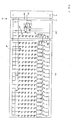
In Figur 6 ist ein Gesamtschaltbild eines
Ausführungsbeispiels der Erfindung, umfassend ein Netzteil 2
und ein LED-Modul 1 mit einem LED-Array 1a und der in Figur 5
gezeigten Schaltung 1b zur Rückmeldung der Helligkeitsstufe
an das Netzteil 2 dargestellt. Optional können weitere Module
zwischen dem Netzteil und dem LED-Array (Pfeil X) vorgesehen
sein. Dies wird im Zusammenhang mit Figur 7 genauer
erläutert.In Figure 6 is an overall circuit diagram of a
Embodiment of the invention, comprising a
Das LED-Array 1a weist eine Mehrzahl parallelgeschalteter
LED-Ketten 14 auf. Die LED-Ketten 14 und die Referenz-LED-Kette
11 werden jeweils mit dem gleichen Strom betrieben.
Hierzu die dient jeweils die anodenseitigen Serienschaltung
der LED-Kette mit der Basis-Emitterstrecke eines Transistors
TK und eines Emitterwiderstands RE sowie die Verbindung der
Basisanschlüsse dieser Transistoren. Die Emitterwiderstände
weisen dabei denselben Wert auf. Alternativ können auch
unterschiedliche Emitterwiderstände vorgesehen sein, wobei
dann eine Aufteilung der Ströme in den LED-Ketten
entsprechend den reziproken Emitterwiderstandswerten erfolgt.
Durch die Verbindung des jeweiligen Kollektors mit der Basis
bei den Transistoren TK über die Dioden DK und die
Widerstände RK wird ein für den stabilen Betrieb der
Transistoren TK erforderlicher Basisstrom aus den LED-Ketten
abgezweigt. Wenn eine LED-Kette unterbrochen wird, bleibt
vorteilhafterweise die eingestellte Stromverteilung auf die
anderen LED-Ketten aufrechterhalten. Ebenso wird der
Kurzschluß einzelner LEDs kompensiert. Insgesamt wird damit
ein Defekt von LEDs in Form eines Kurzschlusses oder einer
Unterbrechung ("Durchbrennen") wirkungsvoll abgefangen.The LED array 1a has a plurality of parallel ones
LED
Wie bereits im Zusammenhang mit den Figuren 5a und 5b
beschrieben wird mittels der Referenz-LED-Kette 11 des LED-Moduls
ein Meßsignal erzeugt, daß von einer optischen
Ausgangsgröße des LED-Moduls, beispielsweise der Helligkeit
abhängt und in Form eines Widerstands zwischen den
Anschlüssen 13a und 13b in das Netzteil 2 eingespeist wird.
Entsprechend regelt das Netzteil 2 den Betriebsstrom und/oder
die Betriebsspannung des LED-Moduls so, daß eine vorgegebene
optische Soll-Ausgangsgröße, etwa eine Mindesthelligkeit,
eingehalten wird, oder es schaltet das LED-Array ab.As already in connection with Figures 5a and 5b
is described by means of the reference LED chain 11 of the LED module
generates a measurement signal that from an optical
Output variable of the LED module, for example the brightness
depends and in the form of a resistance between the
In Figur 7 sind weitere Schaltungsmodule 16, 17, 18 und 19
dargestellt, die jeweils kumulativ oder alternativ bei der
Erfindung, insbesondere bei einer Schaltung gemäß Figur 6
(Pfeil X), verwendet werden können.7 shows
Modul 16 umfaßt einen Transistor, der einen "künstlichen
Kurzschluß" hervorrufen kann. Seitens des Netzteils 2 wird
bei einem solchen künstlichen Kurzschluß die elektrische
Versorgung des LED-Moduls unterbrochen oder sogar das gesamte
Netzteil abgeschaltet. Vorzugsweise ist hierfür eine
Schmelzsicherung vorgesehen, die die Versorgungsleitung
irreversibel unterbricht.
Dieses Modul 16 wird bevorzugt mit einer Schaltung gemäß
Modul 18 angesteuert, in das wiederum mittels einer
Signalleitung 20 (vgl. Figur 6) ein Signal eingespeist wird,
das den Ausfall einer oder mehrerer LED-Ketten des LED-Arrays
anzeigt.This
Falls das Netzteil nicht zur Verarbeitung eines "künstlichen
Kurzschlusses" ausgelegt ist, kann auch mittels Modul 16 und
17 ein entsprechendes, den Ausfall von LED-Ketten anzeigendes
Signal für die Steuerleitung 13a, 13b des Netzteils generiert
werden.If the power supply is not for processing an "artificial
Short circuit "is also designed using
In Modul 18 ist schließlich ein Einstellwiderstand und/oder
ein thermischer Widerstand vorgesehen, der ebenfalls in das
Meßsignal zwischen den Steuerleitungen 13a und 13b einfließt.
Hiermit können beispielsweise Änderungen der
Betriebstemperatur und eine damit verbundene Änderung der
Helligkeit des LED-Array berücksichtigt werden.Finally, in
Die Erläuterung der Erfindung anhand der Ausführungsbeispiele ist selbstverständlich nicht als Beschränkung der Erfindung hierauf zu verstehen. Vielmehr können einzelne Aspekte der verschiedenen Ausführungsbeispiele im Rahmen der Erfindung frei kombiniert werden.The explanation of the invention using the exemplary embodiments is of course not a limitation of the invention to understand this. Rather, individual aspects of the various embodiments within the scope of the invention can be freely combined.
Claims (13)
dadurch gekennzeichnet, daß
ein von einer optischen Ausgangsgröße des LED-Moduls (1) abhängiges Meßsignal (6) erzeugt wird, das Meßsignal (6) in das Netzteil (2) eingespeist wird, und das Netzteil (2) die elektrische Versorgung des LED-Moduls (2) so anhand des Meßsignals (6) regelt, daß im Betrieb das LED-Modul (1) eine vorgegebene optische Soll-Ausgangsgröße einhält, und/oder das Netzteil (2) in Abhängigkeit des Meßsignals (6) die elektrische Versorgung des LED-Moduls (1) unterbricht.Lighting arrangement with an LED module (1) and a power pack (2) for the electrical supply of the LED module,
characterized in that
a measurement signal (6) which is dependent on an optical output variable of the LED module (1) is generated, the measurement signal (6) is fed into the power pack (2), and the power pack (2) supplies the electrical power to the LED module (2) regulates on the basis of the measurement signal (6) that during operation the LED module (1) complies with a predetermined optical target output variable and / or the power supply unit (2) depending on the measurement signal (6) regulates the electrical supply to the LED module ( 1) interrupts.
dadurch gekennzeichnet, daß
die optische Ausgangsgröße beziehungsweise die optische Soll-Ausgangsgröße die Helligkeit, die gesamte optische Ausgangsleistung, die Gesamtlichtstärke, die Lichtstärkeverteilung, die Leuchtdichte oder eine Funktion dieser Größen ist.Lighting arrangement according to claim 1,
characterized in that
the optical output variable or the optical target output variable is the brightness, the total optical output power, the total light intensity, the light intensity distribution, the luminance or a function of these variables.
dadurch gekennzeichnet, daß
die optische Soll-Ausgangsgröße mittels eines Ansteuermoduls (3) für das Netzteil (2) vorgegeben wird.Lighting arrangement according to claim 1 or 2,
characterized in that
the optical target output variable is specified by means of a control module (3) for the power pack (2).
dadurch gekennzeichnet, daß
das Netzteil (2) eine Vergleichsvorrichtung zum Vergleich der optischen Ausgangsgröße mit der optischen Soll-Ausgangsgröße enthält, wobei bei einer vorgegebenen Abweichung der optischen Ausgangsgröße von der optischen Soll-Ausgangsgröße das Netzteil die elektrische Versorgung des LED-Moduls (1) unterbricht.Lighting arrangement according to claim 3,
characterized in that
the power supply unit (2) contains a comparison device for comparing the optical output variable with the optical target output variable, the power supply unit interrupting the electrical supply to the LED module (1) in the event of a predetermined deviation of the optical output variable from the optical target output variable.
dadurch gekennzeichnet, daß
das Netzteil (2) beim Erreichen eines vorgegebenen Maximalwertes der elektrischen Versorgung die elektrische Versorgung des LED-Moduls (1) unterbricht.Lighting arrangement according to one of claims 1 to 4,
characterized in that
the power supply unit (2) interrupts the electrical supply of the LED module (1) when a predetermined maximum value of the electrical supply is reached.
dadurch gekennzeichnet, daß
das LED-Modul (1) eine Vorrichtung zum Erzeugen eines eine Fehlfunktion des LED-Moduls (1) anzeigenden Signals umfaßt, das in das Netzteil eingespeist wird, und
das Netzteil vermittels dieses Signals die elektrische Versorgung des LED-Moduls (1) unterbricht.Lighting arrangement according to one of claims 1 to 5,
characterized in that
the LED module (1) comprises a device for generating a signal indicating a malfunction of the LED module (1), which is fed into the power supply unit, and
the power supply unit uses this signal to interrupt the electrical supply to the LED module (1).
dadurch gekennzeichnet, daß
das Netzteil (2) die elektrische Versorgung des LED-Moduls (1) irreversibel, insbesondere vermittels einer Zerstörung eines definierten Bauteils, unterbricht.Lighting arrangement according to one of claims 4 to 6,
characterized in that
the power supply unit (2) irreversibly interrupts the electrical supply to the LED module (1), in particular by destroying a defined component.
dadurch gekennzeichnet, daß
zur Unterbrechung der elektrischen Versorgung des LED-Moduls (1) eine Schmelzsicherung vorgesehen ist.Lighting arrangement according to claim 7,
characterized in that
A fuse is provided to interrupt the electrical supply to the LED module (1).
dadurch gekennzeichnet, daß
das LED-Modul eine Mehrzahl von parallel geschalteten LED-Ketten (14) umfaßt.Lighting arrangement according to one of claims 1 to 8,
characterized in that
the LED module comprises a plurality of LED chains (14) connected in parallel.
dadurch gekennzeichnet, daß
zur Erzeugung des Meßsignals (6) eine Referenz-LED-Kette (11) vorgesehen ist, die vorzugsweise nur zur Erzeugung des Meßsignals (6) dient.Lighting arrangement according to claim 9,
characterized in that
a reference LED chain (11) is provided for generating the measurement signal (6), which is preferably only used to generate the measurement signal (6).
dadurch gekennzeichnet, daß
das LED-Modul (1) eine Schaltung (22) zur Aufteilung der jeweiligen Betriebsströme der einzelnen LED-Ketten (14) und gegebenenfalls der Referenz-LED-Kette (11) gemäß einer vorgegebenen Stromverteilung umfaßt.Lighting arrangement according to claim 9 or 10,
characterized in that
the LED module (1) comprises a circuit (22) for dividing the respective operating currents of the individual LED chains (14) and optionally the reference LED chain (11) according to a predetermined current distribution.
dadurch gekennzeichnet, daß
die Referenz-LED-Kette (11) und mindestens eine andere LED-Kette (14) mit dem gleichen Betriebsstrom betrieben werden.Lighting arrangement according to one of claims 9 to 11,
characterized in that
the reference LED chain (11) and at least one other LED chain (14) are operated with the same operating current.
dadurch gekennzeichnet, daß
die Beleuchtungsanordnung eine Signalanlage oder ein Ampelanlage ist.Lighting arrangement according to one of claims 1 to 8,
characterized in that
the lighting arrangement is a signal system or a traffic light system.
Applications Claiming Priority (2)
| Application Number | Priority Date | Filing Date | Title |
|---|---|---|---|
| DE10208462A DE10208462A1 (en) | 2002-02-27 | 2002-02-27 | lighting arrangement |
| DE10208462 | 2002-02-27 |
Publications (2)
| Publication Number | Publication Date |
|---|---|
| EP1341402A2 true EP1341402A2 (en) | 2003-09-03 |
| EP1341402A3 EP1341402A3 (en) | 2008-07-16 |
Family
ID=27675050
Family Applications (1)
| Application Number | Title | Priority Date | Filing Date |
|---|---|---|---|
| EP03004441A Withdrawn EP1341402A3 (en) | 2002-02-27 | 2003-02-27 | Lighting device with a LED-module |
Country Status (2)
| Country | Link |
|---|---|
| EP (1) | EP1341402A3 (en) |
| DE (1) | DE10208462A1 (en) |
Cited By (4)
| Publication number | Priority date | Publication date | Assignee | Title |
|---|---|---|---|---|
| EP1753267A1 (en) * | 2005-08-04 | 2007-02-14 | Hella KG Hueck & Co. | Lighting device for vehicle lamps |
| DE102009056809A1 (en) * | 2009-12-04 | 2011-06-09 | Westiform Holding Ag | Neon sign i.e. neon character, has memory storing signal representative of initial brightness of LEDs, and control device controlling current supply device for LEDs so that actual value is brought closer to target value |
| WO2013160446A1 (en) * | 2012-04-26 | 2013-10-31 | Zumtobel Lighting Gmbh | Assembly and method for evaluating the state of an electronic unit used for illumination purposes |
| WO2016050521A1 (en) * | 2014-09-29 | 2016-04-07 | Siemens Aktiengesellschaft | Apparatus and method for monitoring a signal transmitter of a traffic control signal installation, which signal transmitter comprises a light-emitting diode |
Families Citing this family (3)
| Publication number | Priority date | Publication date | Assignee | Title |
|---|---|---|---|---|
| DE10245626A1 (en) * | 2002-09-30 | 2004-04-08 | Osram Opto Semiconductors Gmbh | Circuitry to reduce ripple for LED arrangement, uses detected light intensity of LEDs to adjust to nominal light intensity for LED traffic lights |
| JP4439457B2 (en) | 2005-02-14 | 2010-03-24 | 株式会社小糸製作所 | Vehicle lamp system |
| DE102005023295A1 (en) * | 2005-05-12 | 2006-11-16 | Siemens Ag | Circuit for controlling and monitoring a light signal |
Citations (2)
| Publication number | Priority date | Publication date | Assignee | Title |
|---|---|---|---|---|
| US6095661A (en) | 1998-03-19 | 2000-08-01 | Ppt Vision, Inc. | Method and apparatus for an L.E.D. flashlight |
| US6236331B1 (en) | 1998-02-20 | 2001-05-22 | Newled Technologies Inc. | LED traffic light intensity controller |
Family Cites Families (3)
| Publication number | Priority date | Publication date | Assignee | Title |
|---|---|---|---|---|
| US4983884A (en) * | 1989-08-29 | 1991-01-08 | Amp Incorporated | Constant intensity light source for fiber optic testing |
| US6153985A (en) * | 1999-07-09 | 2000-11-28 | Dialight Corporation | LED driving circuitry with light intensity feedback to control output light intensity of an LED |
| US6344641B1 (en) * | 1999-08-11 | 2002-02-05 | Agilent Technologies, Inc. | System and method for on-chip calibration of illumination sources for an integrated circuit display |
-
2002
- 2002-02-27 DE DE10208462A patent/DE10208462A1/en not_active Withdrawn
-
2003
- 2003-02-27 EP EP03004441A patent/EP1341402A3/en not_active Withdrawn
Patent Citations (2)
| Publication number | Priority date | Publication date | Assignee | Title |
|---|---|---|---|---|
| US6236331B1 (en) | 1998-02-20 | 2001-05-22 | Newled Technologies Inc. | LED traffic light intensity controller |
| US6095661A (en) | 1998-03-19 | 2000-08-01 | Ppt Vision, Inc. | Method and apparatus for an L.E.D. flashlight |
Cited By (5)
| Publication number | Priority date | Publication date | Assignee | Title |
|---|---|---|---|---|
| EP1753267A1 (en) * | 2005-08-04 | 2007-02-14 | Hella KG Hueck & Co. | Lighting device for vehicle lamps |
| DE102009056809A1 (en) * | 2009-12-04 | 2011-06-09 | Westiform Holding Ag | Neon sign i.e. neon character, has memory storing signal representative of initial brightness of LEDs, and control device controlling current supply device for LEDs so that actual value is brought closer to target value |
| WO2013160446A1 (en) * | 2012-04-26 | 2013-10-31 | Zumtobel Lighting Gmbh | Assembly and method for evaluating the state of an electronic unit used for illumination purposes |
| WO2016050521A1 (en) * | 2014-09-29 | 2016-04-07 | Siemens Aktiengesellschaft | Apparatus and method for monitoring a signal transmitter of a traffic control signal installation, which signal transmitter comprises a light-emitting diode |
| US10006616B2 (en) | 2014-09-29 | 2018-06-26 | Siemens Aktiengesellschaft | Device and method for monitoring a signal emitter comprising a light-emitting diode in a light-signal system |
Also Published As
| Publication number | Publication date |
|---|---|
| EP1341402A3 (en) | 2008-07-16 |
| DE10208462A1 (en) | 2003-09-04 |
Similar Documents
| Publication | Publication Date | Title |
|---|---|---|
| DE10323437B4 (en) | Vehicle lighting device | |
| DE102005047610B4 (en) | Lighting control circuit for vehicle lamps | |
| DE102006006778B4 (en) | Vehicle lighting system | |
| EP1161121A2 (en) | Lighting device for a vehicle | |
| DE19707986B4 (en) | Circuit arrangement for operating a discharge lamp | |
| DE102009060791A1 (en) | Light module for a lighting device of a motor vehicle and lighting device of a motor vehicle with such a light module | |
| DE10103611B4 (en) | Circuit arrangement for operating a plurality of bulbs | |
| WO1995012512A1 (en) | Circuit for emitting optical signals | |
| EP0992961B1 (en) | Circuit for operating an illuminated sign | |
| DE602005004167T2 (en) | Electrical circuit for LED signal lamps with a switching threshold for switching between daytime and nighttime operation | |
| EP1233654A1 (en) | Circuit and method for adapting the characteristic curve of an LED | |
| DE102006056148B4 (en) | Method for monitoring the operation of a traffic signal system and traffic control traffic signal system | |
| EP1341402A2 (en) | Lighting device with a LED-module | |
| DE102008034524B4 (en) | emergency pack | |
| EP3124988B1 (en) | Light emitting diode control circuit for a signal generator of an illuminating signal system | |
| DE10329367B4 (en) | LED array, LED module and use of the LED module in a signaling system | |
| EP2947962A1 (en) | Motor vehicle illumination system | |
| DE102010055296A1 (en) | Lamp used in building automation system, has control and/or regulating unit that adjusts power supply voltage as function of signals transmitted through contact terminals, electric current values, type and working stress level | |
| DE10114908A1 (en) | dimmer | |
| DE10121380A1 (en) | Monitoring of LED type displays to ensure they are operating correctly, e.g. for signal displays used with railway switching and control, by monitoring the current drawn by individual display units and the whole unit | |
| DE102007047847B4 (en) | Traffic signal system with signal transmitters and a control device for controlling lights in the signalers | |
| DE10257184B4 (en) | LED array and LED module | |
| DE10206649A1 (en) | display device | |
| EP1286571A2 (en) | Electronically secured power supply for a circuit group and display for variable information | |
| EP3038433A2 (en) | Led light module, signal light with such a light module and method for operating such a light module |
Legal Events
| Date | Code | Title | Description |
|---|---|---|---|
| PUAI | Public reference made under article 153(3) epc to a published international application that has entered the european phase |
Free format text: ORIGINAL CODE: 0009012 |
|
| AK | Designated contracting states |
Kind code of ref document: A2 Designated state(s): AT BE BG CH CY CZ DE DK EE ES FI FR GB GR HU IE IT LI LU MC NL PT SE SI SK TR |
|
| AX | Request for extension of the european patent |
Extension state: AL LT LV MK RO |
|
| RAP1 | Party data changed (applicant data changed or rights of an application transferred) |
Owner name: OSRAM OPTO SEMICONDUCTORS GMBH |
|
| RAP1 | Party data changed (applicant data changed or rights of an application transferred) |
Owner name: OSRAM OPTO SEMICONDUCTORS GMBH |
|
| PUAL | Search report despatched |
Free format text: ORIGINAL CODE: 0009013 |
|
| AK | Designated contracting states |
Kind code of ref document: A3 Designated state(s): AT BE BG CH CY CZ DE DK EE ES FI FR GB GR HU IE IT LI LU MC NL PT SE SI SK TR |
|
| AX | Request for extension of the european patent |
Extension state: AL LT LV MK RO |
|
| 17P | Request for examination filed |
Effective date: 20081114 |
|
| 17Q | First examination report despatched |
Effective date: 20090112 |
|
| AKX | Designation fees paid |
Designated state(s): CH DE FR GB LI |
|
| APBK | Appeal reference recorded |
Free format text: ORIGINAL CODE: EPIDOSNREFNE |
|
| APBN | Date of receipt of notice of appeal recorded |
Free format text: ORIGINAL CODE: EPIDOSNNOA2E |
|
| APBR | Date of receipt of statement of grounds of appeal recorded |
Free format text: ORIGINAL CODE: EPIDOSNNOA3E |
|
| APAV | Appeal reference deleted |
Free format text: ORIGINAL CODE: EPIDOSDREFNE |
|
| APBT | Appeal procedure closed |
Free format text: ORIGINAL CODE: EPIDOSNNOA9E |
|
| STAA | Information on the status of an ep patent application or granted ep patent |
Free format text: STATUS: THE APPLICATION IS DEEMED TO BE WITHDRAWN |
|
| 18D | Application deemed to be withdrawn |
Effective date: 20150901 |