EP1340468B1 - Anterior cervical plating system - Google Patents
Anterior cervical plating system Download PDFInfo
- Publication number
- EP1340468B1 EP1340468B1 EP03076485A EP03076485A EP1340468B1 EP 1340468 B1 EP1340468 B1 EP 1340468B1 EP 03076485 A EP03076485 A EP 03076485A EP 03076485 A EP03076485 A EP 03076485A EP 1340468 B1 EP1340468 B1 EP 1340468B1
- Authority
- EP
- European Patent Office
- Prior art keywords
- plate
- holes
- screw
- washer
- bone
- Prior art date
- Legal status (The legal status is an assumption and is not a legal conclusion. Google has not performed a legal analysis and makes no representation as to the accuracy of the status listed.)
- Expired - Lifetime
Links
Images


Classifications
-
- A—HUMAN NECESSITIES
- A61—MEDICAL OR VETERINARY SCIENCE; HYGIENE
- A61B—DIAGNOSIS; SURGERY; IDENTIFICATION
- A61B17/00—Surgical instruments, devices or methods, e.g. tourniquets
- A61B17/56—Surgical instruments or methods for treatment of bones or joints; Devices specially adapted therefor
- A61B17/58—Surgical instruments or methods for treatment of bones or joints; Devices specially adapted therefor for osteosynthesis, e.g. bone plates, screws, setting implements or the like
- A61B17/68—Internal fixation devices, including fasteners and spinal fixators, even if a part thereof projects from the skin
- A61B17/80—Cortical plates, i.e. bone plates; Instruments for holding or positioning cortical plates, or for compressing bones attached to cortical plates
- A61B17/8033—Cortical plates, i.e. bone plates; Instruments for holding or positioning cortical plates, or for compressing bones attached to cortical plates having indirect contact with screw heads, or having contact with screw heads maintained with the aid of additional components, e.g. nuts, wedges or head covers
- A61B17/8042—Cortical plates, i.e. bone plates; Instruments for holding or positioning cortical plates, or for compressing bones attached to cortical plates having indirect contact with screw heads, or having contact with screw heads maintained with the aid of additional components, e.g. nuts, wedges or head covers the additional component being a cover over the screw head
-
- A—HUMAN NECESSITIES
- A61—MEDICAL OR VETERINARY SCIENCE; HYGIENE
- A61B—DIAGNOSIS; SURGERY; IDENTIFICATION
- A61B17/00—Surgical instruments, devices or methods, e.g. tourniquets
- A61B17/56—Surgical instruments or methods for treatment of bones or joints; Devices specially adapted therefor
- A61B17/58—Surgical instruments or methods for treatment of bones or joints; Devices specially adapted therefor for osteosynthesis, e.g. bone plates, screws, setting implements or the like
- A61B17/68—Internal fixation devices, including fasteners and spinal fixators, even if a part thereof projects from the skin
- A61B17/70—Spinal positioners or stabilisers ; Bone stabilisers comprising fluid filler in an implant
- A61B17/7059—Cortical plates
-
- A—HUMAN NECESSITIES
- A61—MEDICAL OR VETERINARY SCIENCE; HYGIENE
- A61B—DIAGNOSIS; SURGERY; IDENTIFICATION
- A61B17/00—Surgical instruments, devices or methods, e.g. tourniquets
- A61B17/56—Surgical instruments or methods for treatment of bones or joints; Devices specially adapted therefor
- A61B17/58—Surgical instruments or methods for treatment of bones or joints; Devices specially adapted therefor for osteosynthesis, e.g. bone plates, screws, setting implements or the like
- A61B17/68—Internal fixation devices, including fasteners and spinal fixators, even if a part thereof projects from the skin
- A61B17/80—Cortical plates, i.e. bone plates; Instruments for holding or positioning cortical plates, or for compressing bones attached to cortical plates
- A61B17/8033—Cortical plates, i.e. bone plates; Instruments for holding or positioning cortical plates, or for compressing bones attached to cortical plates having indirect contact with screw heads, or having contact with screw heads maintained with the aid of additional components, e.g. nuts, wedges or head covers
- A61B17/8047—Cortical plates, i.e. bone plates; Instruments for holding or positioning cortical plates, or for compressing bones attached to cortical plates having indirect contact with screw heads, or having contact with screw heads maintained with the aid of additional components, e.g. nuts, wedges or head covers wherein the additional element surrounds the screw head in the plate hole
Definitions
- the present invention concerns spinal instrumentation systems, most particularly for use in fixation of the cervical spine. More particularly, the invention pertains to a plating system for use in the treatment of various spinal pathologies.
- the spine is subject to various pathologies that compromise its load bearing and support capabilities.
- the spine is subject to degenerative diseases, the effects of tumors and, of course, fractures and dislocations attributable to physical trauma.
- spinal surgeons have tackled the thorny problems associated with addressing and correcting these pathologies using a wide variety of instrumentation and a broad range of surgical techniques.
- the use of elongated rigid plates has been helpful in the stabilization and fixation of the lower spine, most particularly the thoracic and lumbar spine. These same plating techniques have found a tougher road towards acceptance by surgeons specializing in treatment of the cervical spine.
- the cervical spine can be approached either anteriorly or posteriorly, depending upon the spinal disorder or pathology to be treated.
- Many of the well known surgical exposure and fusion techniques of the cervical spine are described in a publication entitled Spinal Instrumentation , edited by Drs. Howard An and Jerome Cotler. This text also describes instrumentation that has been developed in recent years for application to the cervical spine, most frequently from an anterior approach.
- the anterior approach to achieving fusion of the cervical spine has become the most popular approach.
- the fusions occurred without internal instrumentation, relying instead upon external corrective measures such as prolonged recumbent traction, the use of halo devices or minerva casts, or other external stabilization.
- plating systems have become predominant for this type of spinal surgery.
- fixation plates can be useful in stabilizing the upper or lower cervical spine in traumatic, degenerative, tumorous or infectious processes. Moreover, these plates provide the additional benefits of allowing simultaneous knurled decompression with immediate stability.
- the plate must provide strong mechanical fixation that can control movement of each vertebral motion segment in six degrees of freedom.
- the plate must also be able to withstand axial loading in continuity with each of the three columns of the spine.
- the plating system must be able to maintain stress levels below the endurance limits of the material, while at the same time exceeding the strength of the anatomic structures or vertebrae to which the plating system is engaged.
- the thickness of the plate must be small to lower its prominence, particularly in the smaller spaces of the cervical spine.
- the screws used to connect the plate to the vertebrae must not loosen over time or back out from the plate.
- the plate should be designed to contact the vertebrae for greater stability.
- the plate must satisfy certain mechanical requirements, it must also satisfy certain anatomic and surgical considerations.
- the cervical plating system must minimize the intrusion into the patient and reduce the trauma to the surrounding soft tissue.
- the complications can be very devastating, such as injury to the brain stem, spinal cord or vertebral arteries. It has also been found that optimum plating systems permit the placement of more than one screw in each of the instrumented vertebrae.
- bone screws can be supported in a spinal plate in either a rigid or a semi-rigid fashion.
- the bone screws are not permitted any micro-motion or angular movement relative to the plate.
- the bone screw can move somewhat relative, to the plate during the healing process of the spine.
- semi-rigid fixation is preferable for the treatment of degenerative diseases of the spine.
- the presence of a screw capable of some rotation ensures continual loading of the graft. This continual loading avoids stress shielding of the graft, which in turn increases the rate of fusion and incorporation of the graft into the spine.
- rigid screw fixation is believed to be preferable in the treatment of tumors or trauma to the spine, particularly in the cervical region. It is believed that tumor and trauma conditions are better treated in this way because the rigid placement of bone screws preserves the neuro-vascular space and provides for immediate stabilization. It can certainly be appreciated in the case of a burst fracture or large tumorous destruction of a vertebra that immediate stabilization and preservation of the disc space and neuro space is essential.
- the semi-rigid fixation is preferable for degenerative diseases because this type of fixation allows for a dynamic construct.
- a bone graft is universally utilized to maintain either the disc space and/or the vertebral body itself. In most cases, the graft will settle or be at least partially reabsorbed into the adjacent bone.
- a dynamic construct such as that provided by semi-rigid bone screw fixation, will compensate for this phenomenon.
- WO-A-941774 discloses an anterior cervical plating system including an elongated plate having pairs of screw bores at opposite ends to accommodate fixed angle bone screws. A single locking screw is provided at each end to engage heads of said bone screws to firmly and rigidly fix the screws to the plate.
- WO-A-9629948 discloses a bone plate defining a plurality of holes for accommodating bone screws. Fixed and variable angle screws are described. Fixing means in the form of a screw connection is described which rigidly fixes the fixed angle screws to the plate.
- the present invention contemplates a novel system for anterior fixation of the spine utilizing an elongated fixation plate.
- the fixation plate is provided with a plurality of holes through which bone screws extend for engagement into a number of vertebrae.
- the screw holes include a spherical portion to receive a complementary formed spherical head of the bone screw.
- the screw holes further include a cylindrical portion integral with the cylindrical portion and opening to the bottom of the plate.
- the flexibility of the present invention anterior fixation plating system is accomplished by the provision of a fixed angle and a variable angle screw that can be supported within the same screw hole in the plate.
- Each of the screws includes a threaded shank for screwing into a vertebra and in the preferred embodiment a spherical head to seat within the spherical recess. Both screws include an intermediate portion between the spherical head and the threaded shank that is configured to reside within the cylindrical portion of the screw hole when the screw is fixed to the plate.
- the intermediate portion of the fixed angle screw preferably is cylindrical and has an outer diameter sized for a close fit within the cylindrical portion of the screw hole. In this manner, the fixed angle screw is prevented from rotating or pivoting within the screw hole.
- a locking assembly for locking the bone screws in the plate, thereby preventing screw back-out.
- the locking assembly includes a washer that resides within a recess in the plate. The recess overlaps at least one screw hole in the plate so that the washer can be seated above the head of the bone screw to hold the screw in place.
- the locking assembly further includes a threaded set screw that is engaged within a tapped bore concentrically situated within the washer recess.
- the locking washer is itself configured with a recess so that the head of the locking screw can reside essentially flush within the locking washer.
- the locking assembly includes a locking washer having cut-outs formed in its outer surface facing the bone screw head.
- the cut-outs preferably correspond to the shape of the screw hole so that the washer does not overlap the screw hole in the region of the cut-out.
- the washer is held to the plate by a set screw to permit rotation of the washer from a first position in which the cut-outs are aligned with the screw holes, to a second position in which the outer surface of the washer overlaps the screw holes to lock the screw heads in position.
- the washer includes a number of keys projecting from its underside that are configured to mate within corresponding notches formed in the locking washer recess. The notch and key configuration essentially locks the washer in its position overlapping the screw holes.
- the fixation plate assembly of the present invention further contemplates various screw hole arrangements that permit clamping of multiple screws by a single locking assembly.
- Other hole arrangements are provided that offer several screw fixation options to the surgeon when instrumenting one or more vertebrae. For instance, a four hole arrangement is set forth in which four screw holes a spaced at 90° intervals around a single locking washer and screw assembly. The surgeon can insert either fixed or variable angle screws into any one or more of the four screw holes depending upon the vertebral anatomy.
- fixation plate and locking assembly maintain a low profile within the spine.
- a further benefit is accomplished by the ability to select either a fixed angle or a variable angle screw at any instrumented level and within a single fixation plate.
- the plating system includes an elongated plate 31 and a number of bone screws 32.
- the bone screws are held to the plate 31 by way of a plurality of locking assemblies 33.
- the elongated plate 31 is provided with a plurality of screw holes 34 in a variety of arrangements.
- the plate also can be divided into vertebral level nodes 35 so that the sides of the plate give a serpentine appearance.
- the plate 31 includes recesses between each of the nodes 35 to reduce the outer contour and size of the plate.
- the reduced width portion between each of the nodes 35 provides an area of reduced material for additional bending of the plate as may be required by the spinal anatomy.
- the plate 31 preferably includes a rounded upper edge 36 that would be in contact with the soft tissue surrounding the spine.
- the rounded edge 36 reduces the amount of trauma that would be experienced by the surrounding soft tissue.
- the bottom surface 37 of the plate 31 is preferably configured to contact and engage the vertebral bodies at each of the instrumented levels of the spine. In some embodiments, the bottom surface can be textured to enhance its grip on the vertebral body.
- FIGS. 3(a)-3(g) several variations of the elongated plate 31 are depicted.
- the plate depicted in FIGS. 1, 2 and 3(a) includes five vertebral level nodes 35a so that the plate can be engaged to five vertebrae of the spine.
- the plate 31a of FIG. 3(a) could be used to fix the vertebrae C1-C5.
- the elongated plates 31b depicted in FIG. 3(b) is sized and configured to span three or four vertebrae, depending upon the instrumented vertebral levels.
- the plate 31b includes four vertebral level nodes 35b, with two nodes at the opposite ends of the plate and two nodes offset from each other in the middle portion of the plate.
- the elongated plates 31a-31g provide a variety of hole patterns at each of the vertebral level nodes 35a-35g. These hole patterns provide, at a minimum, for at least two bone screws to be engaged into each respective vertebra. As discussed above, it has been found that the placement of two or more screws in each vertebral body improves the stability of the construct. It is one object of the present invention not only to provide for multiple screw placement in each vertebral body, but also to provide means for locking the screws to the elongated plate to prevent backout or loosening of the bone screws. Consequently, various hole patterns are contemplated that address these objects.
- One pattern is an end hole pattern 38, as shown at the ends of plate 31 in FIG. 1 and plate 31a in FIG.
- two screw holes 34 are laterally disposed at a single node 35a.
- a single locking assembly is disposed between the two screw holes 34 and is configured to lock bone screws disposed within each respective hole.
- a similar arrangement is provided by the middle hole pattern 39 in which two screw holes are situated at a single vertebral level.
- a locking assembly is disposed between the two bone screw holes and is configured to lock bone screws within the respective holes in the same manner as screws are locked in the end hole pattern 38.
- the present invention contemplates a plate carrying four-hole patterns.
- the four-hole pattern 40 illustrated in FIG. 1 and FIGS. 3(a) and 3(b), provides four bone screw holes 34 in a diamond pattern.
- a single locking assembly 33 is centrally disposed between all of the bone screw holes so that bone screws within the respective holes are simultaneously locked by the single locking assembly.
- two such four-hole patterns 40 are provided in the five node plate 31a of FIG. 3(a).
- two such four-hole patterns 40 are provided in the three-node plate 31d of FIG. 3(d) only a single four-hole pattern 40 is required. It can be appreciated that the four-hole pattern 40 provides a great degree of flexibility to the surgeon in determining how many bone screws 32 will be engaged into a single vertebra, and in what arrangement. For example, as shown in FIG.
- two screws are situated in the laterally opposite screw holes at the vertebral level node 35.
- bone screws could be placed in the longitudinally opposite screw holes oriented along the length of the plate 31a.
- Less conventional arrangements contemplate bone screws being placed in immediately adjacent screw holes 34, or placing three bone screws in three of the holes of the four-hole pattern 40. Again, the selection of bone screws and their arrangement can be left to the surgeon and will be based upon the type of correction or fixation required and the anatomy of the particular instrumented vertebra.
- a further arrangement for screw holes 34 is provided by the four-hole cluster 41 depicted in FIGS. 3(b) and 3(c).
- the four-hole cluster 41 in plate 31b two hole pairs 41a and 41b are provided.
- Each of the hole pairs includes its own locking assembly to lock the two screws into the screw bores of the respective hole pairs.
- the orientation of the particular hole pairs provides one screw hole from each pair generally laterally relative to each other in a single vertebra.
- the other of the bone screw holes in each respective pair is longitudinally offset from the central screw holes, being disposed closer to the ends of the plate 31b.
- each of the screw holes in the four-hole cluster 41 is generally oriented over or slightly offset from a single vertebra. The surgeon then has the option to selected any of the screw holes in the two hole pairs 41a or 41b that is optimally aligned over the vertebra.
- the plate 31C which includes a four-hole cluster 42.
- the four-hole cluster 42 includes two hole pairs 42a and 42b, in a manner similar to the four-hole cluster 41 of FIG. 3(b); however in this case, the hole pairs are arranged closer to each other, principally because the plate 31c is shorter than the plate 31b.
- the locking assemblies are provided to lock only a pair of bone screw holes rather than all four holes with a single locking assembly.
- the invention further contemplates a three-hole pattern, such as pattern 43 provided in the plate 31f in FIG. 3(f).
- a single locking assembly is used to fix three bone screws within the respective screw holes.
- a five-hole pattern 44 is provided on plate 31g, as shown in FIG. 3(g).
- a single hole is arranged centrally between four outlying holes.
- Two locking assemblies 33 are provided to lock a pair of the outlying four screw holes together with the central hole. In this configuration, the central hole is held in place by two locking assemblies, while each of the outlying four holes is held in place by a single locking assembly.
- the bone screw 32 can either constitute a fixed angle screw 50, as shown in FIG. 4, or a variable angle screw 60, as shown in FIG 5.
- the fixed angle screw 50 includes a threaded shank 51.
- the threaded shank is preferably configured to engage the cancellous bone of a vertebral body.
- the threaded shank can also include self tapping threads, although the specific illustrated embodiment requires prior drilling and tapping of the vertebral body for insertion of the fixed angle screw 50.
- the screw 50 includes an intermediate portion 52 that is disposed between the threaded shank 51 and the head 54 of the screw.
- the threaded shank 51 extends into the intermediate portion 52 by a thread run-out 53, according to standard thread machining practices.
- the intermediate portion 52 includes a short segment that does not bear any threads. This short segment has an outer diameter D 1 that will assume significance during consideration of the details of the elongated plate 31 discussed herein.
- the head 54 of the fixed angle screw 50 includes a tool recess 55 that is configured to receive a driving tool.
- the tool recess 55 can be a hex recess, or in an alternative embodiment, a TORX* Registered trade mark of Textron Inc. type recess.
- the head 54 includes a truncated or flattened top surface 56 and a spherical surface 57 between the top surface 56 and the intermediate portion 52.
- the head 54 includes a height H 1 between the top surface 56 and the intermediate portion 52.
- the intermediate portion 52 and more specifically the segment between the thread run-out 53 and the head 54, has a height of 1.2mm and a diameter of 4.05mm.
- the height H 1 of the head 54 in this specific embodiment has a dimension of 2.6mm.
- the dimensions of the head 54 and intermediate portion 52 are calibrated for length of the threaded shank 51 of between 10mm and 20mm.
- the bone screws are preferably configured for engagement in the cervical spine.
- the root diameter of the threaded shank 51 is tapered over the first four convolutions to the final root diameter, which is about 2.43mm in the specific embodiment.
- variable angle screw 60 Like the fixed angle screw 50, the variable angle screw 60 includes a threaded shank 61 and an intermediate portion 62. However, in contrast to the fixed angle screw 50, the intermediate portion 62 has an outer diameter D 2 that is approximately equal to the root diameter of the threaded shank 61. In other words, the diameter D 2 of the intermediate portion 62 of the variable angle screw 60 is less than the diameter D 1 of the intermediate portion 52 of the fixed angle screw 50. Like the fixed angle screw 50, the threads of the shank 61 run out into the intermediate portion 62, leaving the portion 62 with a threaded height of about 0.8mm.
- the head 64 has a height ⁇ 2 of about 3.3mm. This greater height is attributable to the smaller diameter D 2 of the intermediate portion 64 relative to the diameter D 1 of the intermediate portion 52 of the fixed angle screw 50. Both the head 54 and the head 64 of the respective screws have a comparable outer diameter, which is 4.88mm in the specific embodiment.
- the diameter of the spherical surface 67 continues around a greater arc because the intermediate portion 62 has a smaller diameter.
- the intermediate portion 62 has a diameter D 2 of 2.9mm, compared to the 4.05mm diameter D 1 for the fixed angle screw 50.
- variable angle screw 60 can be preferably provided in lengths between 10mm and 20mm, for use at different locations in the spine.
- the holes are oriented in end hole patterns 38 at opposite ends of the plate, middle hole pattern 39 centrally located in the plate, and two four-hole patterns 40 disposed between the end hole patterns 38 and the middle hole pattern 39.
- the hole patterns require a locking screw assembly 33.
- the plate 31a along with all the other plate design contemplated by the present invention, includes tapped bore 70 situated within a concentric locking recess 71. (See FIG. 7).
- the locking recess 71 intersects or overlaps adjacent bone screw holes 34.
- the locking recess 71 overlaps the two screw holes
- the locking recess 71 overlaps the four holes 34 arranged in a diamond pattern.
- the plate is curved in two degrees of freedom.
- the bottom surface 37 of the plate can be curved along a large radius R, as shown in FIG. 7, to accommodate the kyphotic curvature of the cervical spine.
- the bottom surface 37 forms a medial/lateral curvature L, as shown in FIG. 9, to correspond to the curvature of the vertebral body.
- the plate 31a can be bent along its longitudinal length between the vertebral level nodes 35, as required to accommodate the particular spinal anatomy and vertebral pathology.
- each screw hole 34 in the plate 31a is defined by a spherical recess 75 (see FIGS. 7 and 9) having a diameter measured about an axis 75a intersecting the elongated plate 31a. (See FIGS. 11 and 12).
- the screw holes 34 include a cylindrical bore 77 communicating between the spherical recess 75 and the bottom surface 37 of the plate 31.
- the cylindrical bore 77 defines a diameter along the axis 75a.
- each screw hole 34 includes a flared recess 79.
- the flared recess is preferably formed as a tapered counter-sink along an axis 79a (see FIGS. 11 and 13). This flared recess 79 overlaps the locking recess 71 of the locking assembly 33 at a recess overlap 80, shown best in FIGS. 7, 9 and 13.
- the spherical recess 75 is defined at a diameter of 5.0mm, which is slightly larger than the diameter of the heads 54, 64 of the bone screws 50, 60.
- the cylindrical portion of the screw holes 34 is defined at a diameter of 4.1mm, in the specific embodiment, which is again slightly larger than the diameter D 1 of the intermediate portion 52 of the fixed angle screw 50. It should be understood, of course, that the diameter of the cylindrical bore 77 is significantly larger than the diameter D 2 of the intermediate portion 62 of the variable angle screw 60.
- the axis 75a of both the spherical recess 25 and the cylindrical bore 77 is oriented generally normal to the bottom surface 37 of the plate 31a, when viewed in the direction of the longitudinal axis of the plate. In other words, the axis 75 is normal to the plate in the direction of the medial/lateral curvature L of the plate.
- the orientation of the screw holes 34 can vary between the vertebral level nodes 35, and most particularly when considering the end hole patterns 38.
- the flared recess 79, and specifically its axis 79a can be colinear with the axis 75a of the recess 75, for the hole patterns in the interior of the elongated plate 31a.
- the flared recess 79 can be approximately concentric with the screw holes 34 for the middle hole pattern 39.
- the flared recess 79, and specifically the axis 79a, at the end hole patterns 38, are offset at an angle A, as depicted in FIG. 14.
- the axis 75a of the spherical recess is offset at an angle A of about 12 degrees relative to a perpendicular from the bottom surface 37 of the plate 31a. In this manner, the bone screws will be directed outwardly toward the end of the plate upon insertion into the screw holes 34.
- the locking assembly 33 includes a locking screw 85 having machine threads 86.
- the locking screw 85 terminates in a sharp point 86a to permit penetration of the vertebral body.
- the head 87 of the locking screw 85 includes a lower conical surface 88 and a tool recess 89 defined therein for receiving a driving tool.
- the locking assembly 33 also includes a washer 90 having an outer surface 91.
- the outer surface 91 is defined by a curved convex surface 92.
- the washer 90 also includes a screw bore 93 extending therethrough in communication with a tapered bore 94.
- the tapered bore 94 has a complementary mating configuration relative to the conical surface 88 of the head 87 of locking screw 85.
- the mating conical features between the locking screw and washer provides a self-centering capability for the washer as the locking screw is tightened onto the plate.
- the screw bore 93 is sized to receive the machine threads 86 therethrough for engagement with the tapped bore 70 of the plate 31a, as shown in FIG. 17. As illustrated in FIG.
- the outer surface 91 of the washer 90 intersects the recess overlap 80 between the flared recess 79 and the respective spherical recess 75 of the adjacent screw holes 34.
- the locking recess 71 has a diameter of 6mm to accept the washer 90 having an outer diameter of 5.3mm.
- the curved convex surface 92 of the washer 90 is curved at a radius of about 2.5mm so that the lowermost portion of the washer has a smaller diameter of about 4.3mm.
- the locking assembly 33 is tightened onto the heads 54 of the two bone screws 50.
- the locking screw 85 is threaded into the tapped bore 70 to draw the washer 90 into contact with the screw heads.
- the convex surface 92 seats against the spherical surface 57 of the bone screw heads 54 to firmly seat the screw heads within the plate spherical recess 75.
- the locking washer 90 will advance sufficiently far into the locking recess 71 to rest substantially flush with the top surfaces 56 of the bone screws 50. In the locked position, the washer 90 does not bottom out within the locking recess 71.
- the locking assembly 33 is loosely fixed on the plate 31 so that the surgeon need not fiddle with the locking assembly when the plate is engaged to a vertebra.
- the locking screw 85 is pre-threaded through the locking washer 90 and into the tapped bore 70 until about three or fewer threads of the locking screw project below the bottom surface 37 of the plate.
- the locking screw 85 is then staked at the thread nearest the plate so that the screw cannot be removed or backed out through the tapped bore 70.
- the locking screw 85 can be advanced further through the bore 70- when it is necessary to enable the locking assembly 33.
- the sharp point 86a of the locking screw 85 is preferably configured to penetrate the cortical bone.
- the locking screw 85 helps locate and temporarily stabilize the plate on the vertebra V as the bone screws 50 are implanted into the bone. This temporary location feature provided by the locking screw 85 can also be used when a drill guide is used to drill and tap the vertebra to receive the bone screws 50.
- the locking assembly 33 is configured so that the washer 90 can be moved clear of the screw holes 34 when the locking screw 85 is staked to the plate 31. Thus, even with the locking assembly 33 in its loosened position, the bone screws 50, 60 can still be inserted into the screw holes 34, preferably by pulling the washer 90 away from the plate 31.
- the degree of angulation is restricted by the difference in diameters between the cylindrical bore 77 and the intermediate portion 62 of the variable angle screw 60.
- the relative diameters permit angulation of up to 20° from the axis 75a of the recess 75 and bore 77.
- FIGS. 20-23 A further embodiment of the present invention is depicted in FIGS. 20-23.
- an alternative locking mechanism is provided.
- a plate assembly 100 includes an elongated plate 101 receiving bone screws 102.
- a locking assembly 103 is provided to lock the bone screw within the plate.
- the plate 101 defines a spherical recess 105 to receive the spherical head 115 of the bone screw.
- the threaded shank 114 of the bone screw projects through the recess. It is understood that the bone screw 102 and spherical recess 105 can be similar to the like components described above.
- the locking assembly 103 includes a locking washer 120 and locking screw 121.
- the screw 121 includes machine threads 122 and an enlarged head 123. The head sits within a recess 124 in the washer 120, with the machine threads 122 projecting through a bore 125.
- the machine threads 122 are configured to engage the tapped bore 106 of the plate 101.
- the locking screw 121 can be staked onto the plate 101 as discussed with respect to the prior embodiment.
- the locking washer 120 while functioning similar to the washer of the prior embodiment, offers a different construction than the previous washer.
- the locking washer 120 includes an outer circumferential surface 127 that is preferably convex to mate with a spherical head of the bone screw 102.
- the washer 120 includes cut-outs 128 in the circumferential surface 127. The cut-outs 128 are arranged to coincide with the screw recesses 105 when the locking washer is in a first position, as illustrated in FIG. 21. This structure of the washer 120 allows the washer to remain clear of the recess 105 for unimpeded insertion of the bone screw 102.
- the washer 120 is provided with two such cut-outs at diametrically opposite positions on the washer.
- the cut-outs 128 are aligned with the relative orientation of screw holes 105 in the plate 101.
- a washer 120 adapted for a three hole pattern 43, as depicted in FIG. 3(f) would have three cut-outs 128 at 120° intervals.
- a locking washer 120 modified for use with the four hole pattern 40 of FIG. 3(a) would have four cut-outs 128 spaced 90° apart on the circumferential surface 127 of the washer.
- the locking washer 120 can be rotated into its locking position shown in FIG. 22. In this position, the cut-outs 128 are rotated away from the screw recesses 105 so that the washer, and more particularly the outer circumferential surface 127, overlaps the screw recess 105.
- the washer 120 includes a number of keys 129 an the underside of the washer. The keys are configured to sit within a corresponding notch 110 in the plate 101 when the locking washer is in the locking position shown in FIG. 22. Once the bone screws have been implanted and the locking washer 120 has been rotated into it locking position, the keys 129 fall into the notches 110 to fix the position of the washer while the locking screw 121 is tightened.
Abstract
Description
- The present invention concerns spinal instrumentation systems, most particularly for use in fixation of the cervical spine. More particularly, the invention pertains to a plating system for use in the treatment of various spinal pathologies.
- As with any bony structure, the spine is subject to various pathologies that compromise its load bearing and support capabilities. The spine is subject to degenerative diseases, the effects of tumors and, of course, fractures and dislocations attributable to physical trauma. Throughout the last century, spinal surgeons have tackled the thorny problems associated with addressing and correcting these pathologies using a wide variety of instrumentation and a broad range of surgical techniques. For many years, the use of elongated rigid plates has been helpful in the stabilization and fixation of the lower spine, most particularly the thoracic and lumbar spine. These same plating techniques have found a tougher road towards acceptance by surgeons specializing in treatment of the cervical spine.
- The cervical spine can be approached either anteriorly or posteriorly, depending upon the spinal disorder or pathology to be treated. Many of the well known surgical exposure and fusion techniques of the cervical spine are described in a publication entitled Spinal Instrumentation, edited by Drs. Howard An and Jerome Cotler. This text also describes instrumentation that has been developed in recent years for application to the cervical spine, most frequently from an anterior approach.
- The anterior approach to achieving fusion of the cervical spine has become the most popular approach. During the early years of cervical spine fusion, the fusions occurred without internal instrumentation, relying instead upon external corrective measures such as prolonged recumbent traction, the use of halo devices or minerva casts, or other external stabilization. However, with the advent of the elongated plate customized for use in the cervical spine, plating systems have become predominant for this type of spinal surgery.
- It has been found that many plate designs allow for a mono-cortically or bi-cortically intrinsically stable implant. It has also been found that fixation plates can be useful in stabilizing the upper or lower cervical spine in traumatic, degenerative, tumorous or infectious processes. Moreover, these plates provide the additional benefits of allowing simultaneous knurled decompression with immediate stability.
- During the many years of development of cervical plating systems, particularly for the anterior approach, various needs for such a system have been recognized. For instance, the plate must provide strong mechanical fixation that can control movement of each vertebral motion segment in six degrees of freedom. The plate must also be able to withstand axial loading in continuity with each of the three columns of the spine. The plating system must be able to maintain stress levels below the endurance limits of the material, while at the same time exceeding the strength of the anatomic structures or vertebrae to which the plating system is engaged.
- Another recognized requirements for a plating system is that the thickness of the plate must be small to lower its prominence, particularly in the smaller spaces of the cervical spine. The screws used to connect the plate to the vertebrae must not loosen over time or back out from the plate. Preferably the plate should be designed to contact the vertebrae for greater stability.
- On the other hand, while the plate must satisfy certain mechanical requirements, it must also satisfy certain anatomic and surgical considerations. For example, the cervical plating system must minimize the intrusion into the patient and reduce the trauma to the surrounding soft tissue. In the Spinal Instrumentation text, as well as in other documentation in this field, it is stressed that complications associated with any spinal procedure, and most particularly within the tight confines of cervical procedures, the complications can be very devastating, such as injury to the brain stem, spinal cord or vertebral arteries. It has also been found that optimum plating systems permit the placement of more than one screw in each of the instrumented vertebrae.
- Many spinal plating systems have been developed in the last couple of decades that address some of the needs and requirements for cervical fixation systems. However, even with the more refined plating system designs, there still remains a need for a system that has universal applicability to all pathologies that can be faced by a spinal surgeon in treating the spine. For example, it has been demonstrated that different degrees of fixation of a bone screw relative to the plate are more advantageous for treating certain pathologies as opposed to other pathologies.
- More specifically, it is known that bone screws can be supported in a spinal plate in either a rigid or a semi-rigid fashion. In a rigid fashion, the bone screws are not permitted any micro-motion or angular movement relative to the plate. In the case of a semi-rigid fixation, the bone screw can move somewhat relative, to the plate during the healing process of the spine. It has been determined that semi-rigid fixation is preferable for the treatment of degenerative diseases of the spine. In cases where a graft is implanted to replace the diseased vertebral body, the presence of a screw capable of some rotation ensures continual loading of the graft. This continual loading avoids stress shielding of the graft, which in turn increases the rate of fusion and incorporation of the graft into the spine.
- Similarly, rigid screw fixation is believed to be preferable in the treatment of tumors or trauma to the spine, particularly in the cervical region. It is believed that tumor and trauma conditions are better treated in this way because the rigid placement of bone screws preserves the neuro-vascular space and provides for immediate stabilization. It can certainly be appreciated in the case of a burst fracture or large tumorous destruction of a vertebra that immediate stabilization and preservation of the disc space and neuro space is essential. On the other hand, the semi-rigid fixation is preferable for degenerative diseases because this type of fixation allows for a dynamic construct. In degenerative conditions, a bone graft is universally utilized to maintain either the disc space and/or the vertebral body itself. In most cases, the graft will settle or be at least partially reabsorbed into the adjacent bone. A dynamic construct, such as that provided by semi-rigid bone screw fixation, will compensate for this phenomenon.
- WO-A-941774 discloses an anterior cervical plating system including an elongated plate having pairs of screw bores at opposite ends to accommodate fixed angle bone screws. A single locking screw is provided at each end to engage heads of said bone screws to firmly and rigidly fix the screws to the plate.
- WO-A-9629948 discloses a bone plate defining a plurality of holes for accommodating bone screws. Fixed and variable angle screws are described. Fixing means in the form of a screw connection is described which rigidly fixes the fixed angle screws to the plate.
- At present, no plating system is known that allows for the placement of bone screws in either a semi-rigid or a rigid construct with a single plate. While some plates will provide for either one of these screw fixations, no plating system allows the surgeon to use a single plate and to select which of the two types of fixation is desired for the particular spinal pathology and anatomy.
- According to the present invention there is provided a bone fixation system comprising:
- an elongated fixation plate having a top surface and a bottom surface and defining a plurality of holes through which bone screws may be inserted for engagement into a number of vertebrae, at least one of said plurality of holes including a cylindrical portion opening to the bottom of the plate;
- a first bone engaging fastener having a first threaded shank for screwing into a vertebra, a first enlarged head and a first intermediate portion between the first head and the first shank that is configured to reside within the cylindrical portion of any of the holes when the screw is fixed to the plate, the first intermediate portion having an outer diameter that is significantly smaller than the diameter of the cylindrical portion of the hole such that it is able to assume a range of angles relative to the bottom surface of the plate even when the screw is locked in position in the plate
- a second bone engaging fastener having a second enlarged head, a second threaded shank for screwing into a vertebra and a second intermediate portion between the second head and the second threaded shank, the second intermediate portion being configured to reside within the cylindrical portion of any of the holes when the screw is fixed to the plate such that it is prevented from rotating or pivoting within the hole; and
- In order to address the needs left unfulfilled by prior systems, the present invention contemplates a novel system for anterior fixation of the spine utilizing an elongated fixation plate. In the invention, the fixation plate is provided with a plurality of holes through which bone screws extend for engagement into a number of vertebrae. In the preferred embodiment, the screw holes include a spherical portion to receive a complementary formed spherical head of the bone screw. The screw holes further include a cylindrical portion integral with the cylindrical portion and opening to the bottom of the plate.
- The flexibility of the present invention anterior fixation plating system is accomplished by the provision of a fixed angle and a variable angle screw that can be supported within the same screw hole in the plate. Each of the screws includes a threaded shank for screwing into a vertebra and in the preferred embodiment a spherical head to seat within the spherical recess. Both screws include an intermediate portion between the spherical head and the threaded shank that is configured to reside within the cylindrical portion of the screw hole when the screw is fixed to the plate. The intermediate portion of the fixed angle screw preferably is cylindrical and has an outer diameter sized for a close fit within the cylindrical portion of the screw hole. In this manner, the fixed angle screw is prevented from rotating or pivoting within the screw hole.
- The variable angle bone screw includes an intermediate portion that is also preferably cylindrical. However, the cylindrical intermediate portion of the variable angle screw has an outer diameter that is significantly smaller than the diameter of the cylindrical portion of the screw hole. This relative difference in diameters between the screw intermediate portion and the screw hole allows the screw to assume a range of angles relative to the bottom surface of the plate, even when the screw is locked in position in the plate.
- In the invention, a locking assembly is provided for locking the bone screws in the plate, thereby preventing screw back-out. In one embodiment of the invention, the locking assembly includes a washer that resides within a recess in the plate. The recess overlaps at least one screw hole in the plate so that the washer can be seated above the head of the bone screw to hold the screw in place. The locking assembly further includes a threaded set screw that is engaged within a tapped bore concentrically situated within the washer recess. The locking washer is itself configured with a recess so that the head of the locking screw can reside essentially flush within the locking washer.
- In a further embodiment, the locking assembly includes a locking washer having cut-outs formed in its outer surface facing the bone screw head. The cut-outs preferably correspond to the shape of the screw hole so that the washer does not overlap the screw hole in the region of the cut-out. The washer is held to the plate by a set screw to permit rotation of the washer from a first position in which the cut-outs are aligned with the screw holes, to a second position in which the outer surface of the washer overlaps the screw holes to lock the screw heads in position. In a further aspect, the washer includes a number of keys projecting from its underside that are configured to mate within corresponding notches formed in the locking washer recess. The notch and key configuration essentially locks the washer in its position overlapping the screw holes.
- The fixation plate assembly of the present invention further contemplates various screw hole arrangements that permit clamping of multiple screws by a single locking assembly. Other hole arrangements are provided that offer several screw fixation options to the surgeon when instrumenting one or more vertebrae. For instance, a four hole arrangement is set forth in which four screw holes a spaced at 90° intervals around a single locking washer and screw assembly. The surgeon can insert either fixed or variable angle screws into any one or more of the four screw holes depending upon the vertebral anatomy.
- It is one object of the invention to provide a fixation plate assembly that accommodates either fixed or variable angle screw fixation in a single plate. Another object resides in the provision of a locking assembly that can lock one or more bone screws within the plate.
- One benefit achieved by the present invention is that the fixation plate and locking assembly maintain a low profile within the spine. A further benefit is accomplished by the ability to select either a fixed angle or a variable angle screw at any instrumented level and within a single fixation plate.
- Other objects and benefits of the invention will become apparent upon consideration of the following written description of the invention, together with the accompanying figures.
-
- FIG. 1 is a top perspective view of an anterior plating system according to one embodiment of the present invention.
- FIG. 2 is a side elevational view of the plating system shown in FIG. 1.
- FIGS. 3(a)-3(g) are top elevational views of a fixation plate in accordance with the present invention provided in different sizes and configuration.
- FIG. 4 is a side elevational view of a fixed-angle bone screw forming part of one embodiment of the present invention.
- FIG. 5 is a side elevational view of a variable angle bone screw forming part of another embodiment of the present invention.
- FIG. 6 is a top elevational view of one embodiment of an elongated plate for use in the anterior plating system according to the present invention.
- FIG. 7 is a side cross-sectional view of the plate shown in FIG. 6 taken along line 7-7 as viewed in the direction of the arrows.
- FIG. 8 is an end elevational view of the plate shown in FIG. 6.
- FIG. 9 is an end cross-sectional view of the plate shown in FIG. 6 taken along line 9-9 as viewed in the direction of the arrows.
- FIG. 10 is a partial side view of a portion of the plate shown in FIG. 6, particularly illustrating the four-hole pattern for the bone screw holes.
- FIG. 11 is a partial side view of an end of the plate in FIG. 6, particularly showing the end hole pattern of bone screw holes.
- FIG. 12 is a transverse cross-sectional view of the end hole pattern of the plate in FIG. 6, particularly taken along line 12-12 in FIG. 11 as viewed in the direction of the arrows.
- FIG. 13 is an end transverse cross-sectional view of the end of the plate shown in FIG. 6, particularly taken along line 13-13 in FIG. 11 as viewed in the direction of the arrows.
- FIG. 14 is a cross-sectional view of one bone screw opening in the end hole pattern of the plate shown in FIG. 6, particularly taken along line 14-14 in FIG. 8 as viewed in the direction of the arrows.
- FIG. 15 is an enlarged side elevational view of a locking screw forming part of one embodiment of the present invention.
- FIG. 16 is an enlarged side elevational view of a locking washer forming part of another embodiment of the present invention.
- FIG. 17 is a partial cross-sectional view of an end hole pattern of the plate shown in FIG. 6, with the screw and washer of FIGS. 15 and 16, respectively shown in their operative position.
- FIG. 18 is a partial cross-sectional view of a plate according to the present invention with the fixed angle bone screws disposed within bone holes in a plate and engaged within a vertebra.
- FIG. 19 is an enlarged end cross-sectional view of the plate according to the present invention with variable angle screws disposed in the plate and engaged in a vertebra.
- FIG. 20 is an exploded view of an alternative embodiment of a locking screw assembly for use in an anterior plating system according to a further embodiment of the invention.
- FIG. 21 is a top perspective view of the components shown in FIG. 20 in the assembled condition with the locking washer shown in its first position.
- FIG. 22 is a top perspective view of the locking screw as depicted in FIG. 20, with the locking washer in its second position.
- FIG. 23 is a side elevational view of one embodiment of the locking washer used in the assembly of FIGS. 20-22.
- For the purposes of promoting an understanding of the principles of the invention, reference will now be made to the embodiment illustrated in the drawings and specific language will be used to describe the same. It will nevertheless be understood that no limitation of the scope of the invention is thereby intended. Any alterations and further modifications in the described device, and any further applications of the principles of the invention as described herein are contemplated as would normally occur to one skilled in the art to which the invention relates.
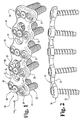
- An anterior plating system or
fixation assembly 30 is depicted in FIGS. 1 and 2. In accordance with the present invention, the plating system includes anelongated plate 31 and a number of bone screws 32. The bone screws are held to theplate 31 by way of a plurality of lockingassemblies 33. Theelongated plate 31 is provided with a plurality of screw holes 34 in a variety of arrangements. The plate also can be divided intovertebral level nodes 35 so that the sides of the plate give a serpentine appearance. In particular, theplate 31 includes recesses between each of thenodes 35 to reduce the outer contour and size of the plate. In addition, the reduced width portion between each of thenodes 35 provides an area of reduced material for additional bending of the plate as may be required by the spinal anatomy. - The
plate 31 preferably includes a roundedupper edge 36 that would be in contact with the soft tissue surrounding the spine. Therounded edge 36 reduces the amount of trauma that would be experienced by the surrounding soft tissue. Thebottom surface 37 of theplate 31 is preferably configured to contact and engage the vertebral bodies at each of the instrumented levels of the spine. In some embodiments, the bottom surface can be textured to enhance its grip on the vertebral body. - Referring now to FIGS. 3(a)-3(g), several variations of the
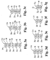
elongated plate 31 are depicted. It is understood that the anterior plating system according to the present invention can be readily adapted to fix several vertebrae, of course depending upon the length of the plate and the number and arrangement of screw holes 34. The plate depicted in FIGS. 1, 2 and 3(a) includes fivevertebral level nodes 35a so that the plate can be engaged to five vertebrae of the spine. For example, theplate 31a of FIG. 3(a) could be used to fix the vertebrae C1-C5. Theelongated plates 31b depicted in FIG. 3(b) is sized and configured to span three or four vertebrae, depending upon the instrumented vertebral levels. In this instance, theplate 31b includes fourvertebral level nodes 35b, with two nodes at the opposite ends of the plate and two nodes offset from each other in the middle portion of the plate. - A modification of the
plate 31b is depicted in FIG. 3(c). In this case, theplate 31c includes threenodes 35c, with the nodes on the opposite side of the middle portion of the plate being directly aligned at the same vertebral level. The plates of FIGS. 3(d)-3(e), namelyplates plate 31c although their lengths are progressively shorter. The last twoplates nodes - In accordance with the present invention, the
elongated plates 31a-31g provide a variety of hole patterns at each of thevertebral level nodes 35a-35g. These hole patterns provide, at a minimum, for at least two bone screws to be engaged into each respective vertebra. As discussed above, it has been found that the placement of two or more screws in each vertebral body improves the stability of the construct. It is one object of the present invention not only to provide for multiple screw placement in each vertebral body, but also to provide means for locking the screws to the elongated plate to prevent backout or loosening of the bone screws. Consequently, various hole patterns are contemplated that address these objects. One pattern is anend hole pattern 38, as shown at the ends ofplate 31 in FIG. 1 andplate 31a in FIG. 3(a). In this arrangement, twoscrew holes 34 are laterally disposed at asingle node 35a. A single locking assembly is disposed between the twoscrew holes 34 and is configured to lock bone screws disposed within each respective hole. A similar arrangement is provided by themiddle hole pattern 39 in which two screw holes are situated at a single vertebral level. A locking assembly is disposed between the two bone screw holes and is configured to lock bone screws within the respective holes in the same manner as screws are locked in theend hole pattern 38. - The present invention contemplates a plate carrying four-hole patterns. The four-
hole pattern 40 illustrated in FIG. 1 and FIGS. 3(a) and 3(b), provides four bone screw holes 34 in a diamond pattern. Asingle locking assembly 33 is centrally disposed between all of the bone screw holes so that bone screws within the respective holes are simultaneously locked by the single locking assembly. In the fivenode plate 31a of FIG. 3(a), two such four-hole patterns 40 are provided. In the three-node plate 31d of FIG. 3(d), only a single four-hole pattern 40 is required. It can be appreciated that the four-hole pattern 40 provides a great degree of flexibility to the surgeon in determining how many bone screws 32 will be engaged into a single vertebra, and in what arrangement. For example, as shown in FIG. 1, two screws are situated in the laterally opposite screw holes at thevertebral level node 35. Alternatively, bone screws could be placed in the longitudinally opposite screw holes oriented along the length of theplate 31a. Less conventional arrangements contemplate bone screws being placed in immediately adjacent screw holes 34, or placing three bone screws in three of the holes of the four-hole pattern 40. Again, the selection of bone screws and their arrangement can be left to the surgeon and will be based upon the type of correction or fixation required and the anatomy of the particular instrumented vertebra. - A further arrangement for screw holes 34 is provided by the four-
hole cluster 41 depicted in FIGS. 3(b) and 3(c). In the four-hole cluster 41 inplate 31b, twohole pairs plate 31b. In this manner, the two central holes of each of the two holes pairs can be engaged in a single vertebra, while the remaining screw holes of the hole pairs 41a and 41b can be disposed in the superior and inferior adjacent vertebrae. Most preferably, however, each of the screw holes in the four-hole cluster 41 is generally oriented over or slightly offset from a single vertebra. The surgeon then has the option to selected any of the screw holes in the twohole pairs - A similar arrangement is found in the plate 31C which includes a four-
hole cluster 42. In this case, it can be seen that the four-hole cluster 42 includes twohole pairs hole cluster 41 of FIG. 3(b); however in this case, the hole pairs are arranged closer to each other, principally because theplate 31c is shorter than theplate 31b. In both of the four-hole clusters - The invention further contemplates a three-hole pattern, such as
pattern 43 provided in theplate 31f in FIG. 3(f). In thispattern 43, a single locking assembly is used to fix three bone screws within the respective screw holes. A five-hole pattern 44 is provided onplate 31g, as shown in FIG. 3(g). In this five-hole pattern, a single hole is arranged centrally between four outlying holes. Twolocking assemblies 33 are provided to lock a pair of the outlying four screw holes together with the central hole. In this configuration, the central hole is held in place by two locking assemblies, while each of the outlying four holes is held in place by a single locking assembly. - In one important feature of the present invention, the
bone screw 32 can either constitute a fixedangle screw 50, as shown in FIG. 4, or avariable angle screw 60, as shown in FIG 5. Turning first to FIG. 4, the fixedangle screw 50 includes a threadedshank 51. The threaded shank is preferably configured to engage the cancellous bone of a vertebral body. The threaded shank can also include self tapping threads, although the specific illustrated embodiment requires prior drilling and tapping of the vertebral body for insertion of the fixedangle screw 50. Thescrew 50 includes anintermediate portion 52 that is disposed between the threadedshank 51 and thehead 54 of the screw. The threadedshank 51 extends into theintermediate portion 52 by a thread run-out 53, according to standard thread machining practices. As can be seen from FIG. 4, theintermediate portion 52 includes a short segment that does not bear any threads. This short segment has an outer diameter D1 that will assume significance during consideration of the details of theelongated plate 31 discussed herein. - The
head 54 of the fixedangle screw 50 includes atool recess 55 that is configured to receive a driving tool. In one specific embodiment, thetool recess 55 can be a hex recess, or in an alternative embodiment, a TORX* Registered trade mark of Textron Inc. type recess. Thehead 54 includes a truncated or flattenedtop surface 56 and aspherical surface 57 between thetop surface 56 and theintermediate portion 52. Thehead 54 includes a height H1 between thetop surface 56 and theintermediate portion 52. - In one specific embodiment, the
intermediate portion 52, and more specifically the segment between the thread run-out 53 and thehead 54, has a height of 1.2mm and a diameter of 4.05mm. The height H1 of thehead 54 in this specific embodiment has a dimension of 2.6mm. In this specific embodiment, the dimensions of thehead 54 andintermediate portion 52 are calibrated for length of the threadedshank 51 of between 10mm and 20mm. In this specific embodiment, the bone screws are preferably configured for engagement in the cervical spine. In another aspect of the specific embodiment, the root diameter of the threadedshank 51 is tapered over the first four convolutions to the final root diameter, which is about 2.43mm in the specific embodiment. - Turning to FIG. 5, the details of the
variable angle screw 60 can be seen. Like the fixedangle screw 50, thevariable angle screw 60 includes a threadedshank 61 and anintermediate portion 62. However, in contrast to the fixedangle screw 50, theintermediate portion 62 has an outer diameter D2 that is approximately equal to the root diameter of the threadedshank 61. In other words, the diameter D2 of theintermediate portion 62 of thevariable angle screw 60 is less than the diameter D1 of theintermediate portion 52 of the fixedangle screw 50. Like the fixedangle screw 50, the threads of theshank 61 run out into theintermediate portion 62, leaving theportion 62 with a threaded height of about 0.8mm. - The
variable angle screw 60 also includes ahead 64 having atool recess 65 defined from the truncatedtop surface 66. Thehead 64 also includes aspherical surface 67 disposed between thetop surface 66 and theintermediate portion 62. Thehead 64 of thevariable angle screw 60 has a height H2 between the top surface and the intermediate portion that is greater than the height H1 of thehead 54 of the fixedangle screw 50. - In the specific embodiment of the
variable angle screw 60, thehead 64 has a height Ḣ2 of about 3.3mm. This greater height is attributable to the smaller diameter D2 of theintermediate portion 64 relative to the diameter D1 of theintermediate portion 52 of the fixedangle screw 50. Both thehead 54 and thehead 64 of the respective screws have a comparable outer diameter, which is 4.88mm in the specific embodiment. In the case of the variable angle screw, the diameter of thespherical surface 67 continues around a greater arc because theintermediate portion 62 has a smaller diameter. In one specific embodiment, theintermediate portion 62 has a diameter D2 of 2.9mm, compared to the 4.05mm diameter D1 for the fixedangle screw 50. - Like the fixed
angle screw 50, thevariable angle screw 60 can be preferably provided in lengths between 10mm and 20mm, for use at different locations in the spine. - The engagement of the bone screws 50 and 60 to the
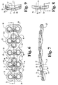
elongated plate 31 require further discussion of the details of the plate itself. These details can be discerned with reference to FIGS. 6-14. In FIG. 6, thelonger plate 31a is depicted, although it is understood that the various geometric structural aspects of this plate are repeated among each of theplates 31b-31g. As discussed previously, theplate 31a includes undulating edges, with the peaks of the undulation corresponding to thevertebral level nodes 35. The plate material between the nodes is reduced to minimize the bulk of the plate and to provide a thinner plate width in areas that may require additional bending for implantation. In the specific embodiment, a plurality of screw holes 34 is provided throughout the length of the plate and in various patterns. In the illustrated embodiment of FIG. 6, the holes are oriented inend hole patterns 38 at opposite ends of the plate,middle hole pattern 39 centrally located in the plate, and two four-hole patterns 40 disposed between theend hole patterns 38 and themiddle hole pattern 39. In each case, the hole patterns require a lockingscrew assembly 33. Consequently, theplate 31a, along with all the other plate design contemplated by the present invention, includes tapped bore 70 situated within aconcentric locking recess 71. (See FIG. 7). As shown in FIGS. 6 and 7, the lockingrecess 71 intersects or overlaps adjacent bone screw holes 34. In the case of theend hole pattern 38, the lockingrecess 71 overlaps the two screw holes, while in the case of the four-hole pattern 40, the lockingrecess 71 overlaps the fourholes 34 arranged in a diamond pattern. - To accommodate the anterior application of this
fixation plate assembly 30, the plate is curved in two degrees of freedom. Specifically, thebottom surface 37 of the plate can be curved along a large radius R, as shown in FIG. 7, to accommodate the kyphotic curvature of the cervical spine. In addition, thebottom surface 37 forms a medial/lateral curvature L, as shown in FIG. 9, to correspond to the curvature of the vertebral body. It is understood that theplate 31a can be bent along its longitudinal length between thevertebral level nodes 35, as required to accommodate the particular spinal anatomy and vertebral pathology. - The screw holes 34 in the
plate 31a are defined by a spherical recess 75 (see FIGS. 7 and 9) having a diameter measured about anaxis 75a intersecting theelongated plate 31a. (See FIGS. 11 and 12). In a further aspect of the invention, the screw holes 34 include acylindrical bore 77 communicating between thespherical recess 75 and thebottom surface 37 of theplate 31. The cylindrical bore 77 defines a diameter along theaxis 75a. To facilitate insertion of drill guides, drills and the bone screws 32, eachscrew hole 34 includes a flaredrecess 79. The flared recess is preferably formed as a tapered counter-sink along anaxis 79a (see FIGS. 11 and 13). This flaredrecess 79 overlaps the lockingrecess 71 of the lockingassembly 33 at arecess overlap 80, shown best in FIGS. 7, 9 and 13. - In one specific embodiment, the
spherical recess 75 is defined at a diameter of 5.0mm, which is slightly larger than the diameter of theheads intermediate portion 52 of the fixedangle screw 50. It should be understood, of course, that the diameter of thecylindrical bore 77 is significantly larger than the diameter D2 of theintermediate portion 62 of thevariable angle screw 60. - Again in the specific embodiment, the
axis 75a of both the spherical recess 25 and thecylindrical bore 77 is oriented generally normal to thebottom surface 37 of theplate 31a, when viewed in the direction of the longitudinal axis of the plate. In other words, theaxis 75 is normal to the plate in the direction of the medial/lateral curvature L of the plate. On the other hand, the orientation of the screw holes 34 can vary between thevertebral level nodes 35, and most particularly when considering theend hole patterns 38. In this specific embodiment, the flaredrecess 79, and specifically itsaxis 79a, can be colinear with theaxis 75a of therecess 75, for the hole patterns in the interior of theelongated plate 31a. For example, as shown in FIG. 6, the flaredrecess 79 can be approximately concentric with the screw holes 34 for themiddle hole pattern 39. On the other hand, the flaredrecess 79, and specifically theaxis 79a, at theend hole patterns 38, are offset at an angle A, as depicted in FIG. 14. In particular, theaxis 75a of the spherical recess is offset at an angle A of about 12 degrees relative to a perpendicular from thebottom surface 37 of theplate 31a. In this manner, the bone screws will be directed outwardly toward the end of the plate upon insertion into the screw holes 34. - The details of the locking
assembly 33 can be gleaned from consideration of FIGS. 15-17. In this specific embodiment, the lockingassembly 33 includes a lockingscrew 85 havingmachine threads 86. In one specific embodiment, the lockingscrew 85 terminates in asharp point 86a to permit penetration of the vertebral body. Thehead 87 of the lockingscrew 85 includes a lower conical surface 88 and atool recess 89 defined therein for receiving a driving tool. - The locking
assembly 33 also includes awasher 90 having anouter surface 91. In the specific preferred embodiment, theouter surface 91 is defined by a curvedconvex surface 92. Thewasher 90 also includes a screw bore 93 extending therethrough in communication with a tapered bore 94. The tapered bore 94 has a complementary mating configuration relative to the conical surface 88 of thehead 87 of lockingscrew 85. The mating conical features between the locking screw and washer provides a self-centering capability for the washer as the locking screw is tightened onto the plate. The screw bore 93 is sized to receive themachine threads 86 therethrough for engagement with the tapped bore 70 of theplate 31a, as shown in FIG. 17. As illustrated in FIG. 17, theouter surface 91 of thewasher 90 intersects the recess overlap 80 between the flaredrecess 79 and the respectivespherical recess 75 of the adjacent screw holes 34. In a specific embodiment, the lockingrecess 71 has a diameter of 6mm to accept thewasher 90 having an outer diameter of 5.3mm. Again in this specific embodiment, the curvedconvex surface 92 of thewasher 90 is curved at a radius of about 2.5mm so that the lowermost portion of the washer has a smaller diameter of about 4.3mm. - Referring now to FIGS. 18 and 19, the use of the
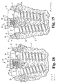
fixation plate assembly 30 is illustrated. In FIG. 18, a pair of fixed angle screws 50 are disposed withinrespective bores 34 so that the threadedshanks 51 project beyond thelower surface 37 of theplate 31 and into the vertebral body V. Theintermediate portion 52 of the fixedangle screw 50 extends through the cylindrical bore 77 of the screw holes 34. Thespherical surface 57 of thehead 54 of the screw contacts thespherical recess 75 of thescrew hole 34 as the fixedangle screw 50 is threaded into the vertebral body V. Once thescrew 50 is completely seated within thespherical recess 75, theintermediate portion 52 provides a snug relationship relative to the cylindrical bore 77 so that the fixedangle screw 50 is not able to pivot or translate relative to theplate 31. - In order to ensure secure fixation of the
screw 50 withinplate 31, the lockingassembly 33 is tightened onto theheads 54 of the two bone screws 50. In particular, the lockingscrew 85 is threaded into the tapped bore 70 to draw thewasher 90 into contact with the screw heads. Theconvex surface 92 seats against thespherical surface 57 of the bone screw heads 54 to firmly seat the screw heads within the platespherical recess 75. Preferably, the lockingwasher 90 will advance sufficiently far into the lockingrecess 71 to rest substantially flush with thetop surfaces 56 of the bone screws 50. In the locked position, thewasher 90 does not bottom out within the lockingrecess 71. - In an embodiment of the invention, the locking
assembly 33 is loosely fixed on theplate 31 so that the surgeon need not fiddle with the locking assembly when the plate is engaged to a vertebra. In particular, the lockingscrew 85 is pre-threaded through the lockingwasher 90 and into the tapped bore 70 until about three or fewer threads of the locking screw project below thebottom surface 37 of the plate. The lockingscrew 85 is then staked at the thread nearest the plate so that the screw cannot be removed or backed out through the tapped bore 70. Of course, the lockingscrew 85 can be advanced further through the bore 70- when it is necessary to enable the lockingassembly 33. As previously mentioned, thesharp point 86a of the lockingscrew 85 is preferably configured to penetrate the cortical bone. With the locking screw staked to the plate, thesharp point 86a will penetrate the vertebra V when theplate 31 is initially positioned on the bone. In this instance, the lockingscrew 85 helps locate and temporarily stabilize the plate on the vertebra V as the bone screws 50 are implanted into the bone. This temporary location feature provided by the lockingscrew 85 can also be used when a drill guide is used to drill and tap the vertebra to receive the bone screws 50. - The locking
assembly 33 is configured so that thewasher 90 can be moved clear of the screw holes 34 when the lockingscrew 85 is staked to theplate 31. Thus, even with the lockingassembly 33 in its loosened position, the bone screws 50, 60 can still be inserted into the screw holes 34, preferably by pulling thewasher 90 away from theplate 31. - The use of the variable
angle bone screw 60 is depicted in FIG. 19. The lockingassembly 33 functions as described above to lock theheads 64 of the variable angle screws 60 within theplate 31. Specifically, theconvex surface 92 of thewasher 90 contacts and applies pressure to thespherical surfaces 67 of the respective bone screws 60. However, with the variable angle screws 60, theintermediate portion 62 does not fit snugly within the cylindrical bore 77 of the screw holes 34. Thus, even with thehead 64 of eachscrew 60 residing solidly within thespherical recess 75, thebone screw 60 can still be angulated relative to the plate and to the axis of thespherical recess 75 andcylindrical bore 77. It is understood that the degree of angulation is restricted by the difference in diameters between thecylindrical bore 77 and theintermediate portion 62 of thevariable angle screw 60. In one preferred embodiment, the relative diameters permit angulation of up to 20° from theaxis 75a of therecess 75 and bore 77. - During implantation, the variable angle capability of the
screw 60 allows the surgeon to place the bone screw within the vertebra at any angle within the defined angulation limits (20° in one specific embodiment). Thus, thevariable angle screw 60 provides greater flexibility than does the fixedangle screw 50 for orienting the bone screw relative to the anatomy of the vertebra. Moreover, this variable angle capability allows a limited degree of micro-motion between the screw and the plate when thefixation assembly 30 is implanted within a patient. In other words, as the spine is loaded and as load is transmitted through the screws and plate, the plate and vertebra may translate relative to each other. Thevariable angle screw 60 accommodates this relative movement by pivoting within thespherical recess 75. On the other hand, the fixedangle screw 50 prevents this relative movement. The choice between using a fixed or a variable angle screw can be left to the surgeon depending upon the pathology being treated. Thefixation plate assembly 30 according to the present invention allows this choice to be made at any point during the surgical procedure. - A further embodiment of the present invention is depicted in FIGS. 20-23. In this embodiment, an alternative locking mechanism is provided. A
plate assembly 100 includes anelongated plate 101 receiving bone screws 102. A lockingassembly 103 is provided to lock the bone screw within the plate. Theplate 101 defines aspherical recess 105 to receive thespherical head 115 of the bone screw. The threadedshank 114 of the bone screw projects through the recess. It is understood that thebone screw 102 andspherical recess 105 can be similar to the like components described above. - In accordance with this embodiment, the plate further includes a tapped bore and
concentric locking recess 107 disposed adjacent thespherical recess 105 for the bone screw. The spherical and locking recess contact at alocking overlap 108. Anotch 110 extends transversely across thelocking recess 107 in this embodiment. - The locking
assembly 103 includes a lockingwasher 120 and lockingscrew 121. Like the prior locking screw, thescrew 121 includesmachine threads 122 and anenlarged head 123. The head sits within arecess 124 in thewasher 120, with themachine threads 122 projecting through abore 125. Themachine threads 122 are configured to engage the tapped bore 106 of theplate 101. The lockingscrew 121 can be staked onto theplate 101 as discussed with respect to the prior embodiment. - The locking
washer 120, while functioning similar to the washer of the prior embodiment, offers a different construction than the previous washer. Like thewasher 90, the lockingwasher 120 includes an outercircumferential surface 127 that is preferably convex to mate with a spherical head of thebone screw 102. However, in one modification, thewasher 120 includes cut-outs 128 in thecircumferential surface 127. The cut-outs 128 are arranged to coincide with the screw recesses 105 when the locking washer is in a first position, as illustrated in FIG. 21. This structure of thewasher 120 allows the washer to remain clear of therecess 105 for unimpeded insertion of thebone screw 102. - In certain embodiments, the
washer 120 is provided with two such cut-outs at diametrically opposite positions on the washer. Most preferably, the cut-outs 128 are aligned with the relative orientation of screw holes 105 in theplate 101. For example, awasher 120 adapted for a threehole pattern 43, as depicted in FIG. 3(f), would have three cut-outs 128 at 120° intervals. Similarly, a lockingwasher 120 modified for use with the fourhole pattern 40 of FIG. 3(a) would have four cut-outs 128 spaced 90° apart on thecircumferential surface 127 of the washer. - Once the bone screws have been implanted through the appropriate screw recesses 105, the locking
washer 120 can be rotated into its locking position shown in FIG. 22. In this position, the cut-outs 128 are rotated away from the screw recesses 105 so that the washer, and more particularly the outercircumferential surface 127, overlaps thescrew recess 105. In a further modification from the prior washer, thewasher 120 includes a number ofkeys 129 an the underside of the washer. The keys are configured to sit within acorresponding notch 110 in theplate 101 when the locking washer is in the locking position shown in FIG. 22. Once the bone screws have been implanted and the lockingwasher 120 has been rotated into it locking position, thekeys 129 fall into thenotches 110 to fix the position of the washer while the lockingscrew 121 is tightened. - While the invention has been illustrated and described in detail in the drawings and foregoing description, the same is to be considered as illustrative and not restrictive in character, it being understood that only the preferred embodiments have been shown and described and that all changes and modifications that come within the scope of the invention as defined in the claims are desired to be protected.
Claims (14)
- A bone fixation system comprising:an elongated fixation plate (31) having a top surface and a bottom surface (37) and defining a plurality of holes (34) through which bone screws (32; 60; 50) may be inserted for engagement into a number of vertebrae, at least one of said plurality of holes including a cylindrical portion opening to the bottom of the plate;a first bone engaging fastener (60) having a first threaded shank (61) for screwing into a vertebra, a first enlarged head (64) and a first intermediate portion (62) between the first head and the first shank that is configured to reside within the cylindrical portion of any of the holes when the screw is fixed to the plate, the first intermediate portion (62) having an outer diameter that is significantly smaller than the diameter of the cylindrical portion of the hole,a second bone engaging fastener (50) having a second enlarged head (54), a second threaded shank (51) for screwing into a vertebra and a second intermediate portion (52) between the second head and the second threaded shank, the second intermediate portion being configured to reside within the cylindrical portion of any of the holes when the screw is fixed to the plate such that it is prevented from rotating or pivoting within the hole (54); andcharacterised in that there is provided a locking assembly (33) for locking the bone engaging fasteners (50, 60) in the plate (31). Such that the first bone engaging fastener (60) is able to move within a range of angles relative to the bottom surface of the plate even when it is locked in position in the plate.
- The bone fixation system of claim 1, wherein the locking screw assembly (33) is for locking said heads of said bone engaging fasteners (50; 60).
- The bone fixation system of claim 2, wherein the plate has a spherical recess portion (75) of said plate (31) into which the heads of the fasteners are locked.
- The bone fixation system of claim 3, wherein the first and second enlarged heads (64; 54) define partially spherical surfaces (67; 57) complementary to said spherical recess portion (75) of said plate (31).
- The bone fixation system of claim 3 or 4, wherein the spherical recess portion (75) has a diameter which is greater than the diameter of the opening of the cylindrical portion of the hole defined at the bottom of the plate (31).
- The bone fixation system of claim 3, 4 or 5, wherein the locking assembly (33) comprises a fastener bore (70) defined in said plate (31) adjacent at least one of said plurality of holes (34);
a washer (90) defining a central aperture (93) and a recess (94) communicating with said aperture, said washer further having an outer circumferential surface (91) configured to contact said head of said first and/or second bone engaging fastener when said first and/or second bone engaging fastener(s) is/are extended through said hole(s); and
a locking fastener (85) having a head (87) configured to be recessed within said recess of said washer and an elongated shank extending through said central aperture and configured to engage said fastener bore of said plate. - The bone fixation system of claim 6, wherein said outer circumferential surface (91) of said washer (90) has a concave curvature substantially corresponding to said partially spherical surface (67; 57) of said head (65; 54) of said first and/or second bone engaging fastener(s) (60; 50).
- The bone fixation system of claim 7, wherein the head (87) of the locking fastener (85) is configured to engage said washer (90).
- The bone fixation system of claim 6, 7 or 8, wherein the washer (90) further defines a bottom surface configured to contact said head (64; 54) of the first and/or second bone engaging fastener(s) (60; 50).
- The bone fixation system of any one of claims 6 to 9, wherein the outer circumferential surface (91) of the washer (90) has a first portion overlapping said hole(s) (34) when said washer is in a first position relative to said hole(s) and having a second portion that does not overlap said hole(s) when said washer is rotated from said first position to a second position, whereby said first and/or second bone engaging fastener(s) (60; 50) can be inserted through said hole(s) with said washer engaged to said plate (31) when said washer is in said second position.
- The bone fixation system of any one of claims 6 to 10, wherein the locking screw assembly (33) further comprises a notch (110) defined in said plate (31) adjacent said fastener bore (70) and said washer further includes a key (129) adjacent said central aperture configured to seat within said notch on said plate to prevent rotation of said washer relative to said plate.
- The bone fixation system of any one of claims 1 to 11, wherein the system comprises four of said bone engaging fasteners (32);
said elongated plate (31) being sized to span between at least three vertebrae, said plate defining a set of four adjacent holes (34), each configured to receive said threaded shank of said bone engaging fasteners; and
said locking screw (33) assembly having a washer (90) configured to overlap each of said four holes when a bone engaging fastener is extended through a corresponding one of said four holes. - The bone fixation system of any one of claims 1 to 11, wherein the system comprises four of said bone engaging fasteners;
said elongated plate being sized to span between at least three vertebrae, said plate defining two sets of holes, each configured to receive said threaded shank of said bone engaging fasteners therethrough, a first set having a first hole aligned over a first vertebra and a second hole aligned over a second vertebra when said plate spans the vertebrae, and a second set having a third hole adjacent said second hole and aligned over the second vertebra, and a fourth hole aligned over a third vertebra adjacent the second vertebra; and
a pair of said locking screw assemblies, one each for each of said two sets of two holes, each of said locking screw assemblies having a washer configured to overlap each of said two holes of said first and second sets when a bone engaging fastener extends through a corresponding one of said holes. - The bone fixation system of any one of claims 1 to 11, wherein the system comprises five of said bone engaging fasteners;
said elongated plate being sized to span between at least three vertebrae, said plate defining three sets of two holes, each configured to receive said threaded shank of said bone engaging fasteners therethrough, a first set having two holes aligned over a first vertebra, a second set having one hole aligned over a second vertebra when said plate spans the three vertebrae, and a third set having two holes aligned over the third vertebra; and said system further comprises
a pair of said locking screw assemblies, a first one of said locking screw assemblies disposed between said first set and said second set of holes and including a first washer configured to overlap each of said two holes of said first set and said one hole of said second set when a bone engaging fastener extends through a corresponding one of said holes, and a second one of said locking screw assemblies disposed between said second set and said third set of holes and including a second washer configured to overlap said one hole of said second set and each of said two holes of said third set when a bone engaging fastener extends through a corresponding one of said holes.
Priority Applications (1)
| Application Number | Priority Date | Filing Date | Title |
|---|---|---|---|
| EP06076355A EP1702577A3 (en) | 1997-05-15 | 1998-05-12 | Anterior cervical plating system |
Applications Claiming Priority (3)
| Application Number | Priority Date | Filing Date | Title |
|---|---|---|---|
| US85690297A | 1997-05-15 | 1997-05-15 | |
| EP98921137A EP0984728B1 (en) | 1997-05-15 | 1998-05-12 | Anterior cervical plating system |
| US856902 | 2004-05-28 |
Related Parent Applications (1)
| Application Number | Title | Priority Date | Filing Date |
|---|---|---|---|
| EP98921137A Division EP0984728B1 (en) | 1997-05-15 | 1998-05-12 | Anterior cervical plating system |
Related Child Applications (1)
| Application Number | Title | Priority Date | Filing Date |
|---|---|---|---|
| EP06076355A Division EP1702577A3 (en) | 1997-05-15 | 1998-05-12 | Anterior cervical plating system |
Publications (3)
| Publication Number | Publication Date |
|---|---|
| EP1340468A2 EP1340468A2 (en) | 2003-09-03 |
| EP1340468A3 EP1340468A3 (en) | 2003-10-29 |
| EP1340468B1 true EP1340468B1 (en) | 2006-09-20 |
Family
ID=25324748
Family Applications (3)
| Application Number | Title | Priority Date | Filing Date |
|---|---|---|---|
| EP06076355A Withdrawn EP1702577A3 (en) | 1997-05-15 | 1998-05-12 | Anterior cervical plating system |
| EP03076485A Expired - Lifetime EP1340468B1 (en) | 1997-05-15 | 1998-05-12 | Anterior cervical plating system |
| EP98921137A Expired - Lifetime EP0984728B1 (en) | 1997-05-15 | 1998-05-12 | Anterior cervical plating system |
Family Applications Before (1)
| Application Number | Title | Priority Date | Filing Date |
|---|---|---|---|
| EP06076355A Withdrawn EP1702577A3 (en) | 1997-05-15 | 1998-05-12 | Anterior cervical plating system |
Family Applications After (1)
| Application Number | Title | Priority Date | Filing Date |
|---|---|---|---|
| EP98921137A Expired - Lifetime EP0984728B1 (en) | 1997-05-15 | 1998-05-12 | Anterior cervical plating system |
Country Status (12)
| Country | Link |
|---|---|
| US (4) | US6152927A (en) |
| EP (3) | EP1702577A3 (en) |
| JP (3) | JP4106096B2 (en) |
| AT (2) | ATE339923T1 (en) |
| AU (1) | AU731855B2 (en) |
| CA (1) | CA2289681C (en) |
| DE (2) | DE69817341T2 (en) |
| DK (1) | DK0984728T3 (en) |
| ES (2) | ES2272886T3 (en) |
| PT (1) | PT984728E (en) |
| WO (1) | WO1998051226A2 (en) |
| ZA (1) | ZA983955B (en) |
Cited By (4)
| Publication number | Priority date | Publication date | Assignee | Title |
|---|---|---|---|---|
| US8172885B2 (en) | 2003-02-05 | 2012-05-08 | Pioneer Surgical Technology, Inc. | Bone plate system |
| US8900277B2 (en) | 2004-02-26 | 2014-12-02 | Pioneer Surgical Technology, Inc. | Bone plate system |
| US9198769B2 (en) | 2011-12-23 | 2015-12-01 | Pioneer Surgical Technology, Inc. | Bone anchor assembly, bone plate system, and method |
| US9381046B2 (en) | 2007-07-03 | 2016-07-05 | Pioneer Surgical Technology, Inc. | Bone plate system |
Families Citing this family (401)
| Publication number | Priority date | Publication date | Assignee | Title |
|---|---|---|---|---|
| US7959652B2 (en) | 2005-04-18 | 2011-06-14 | Kyphon Sarl | Interspinous process implant having deployable wings and method of implantation |
| US6068630A (en) | 1997-01-02 | 2000-05-30 | St. Francis Medical Technologies, Inc. | Spine distraction implant |
| US7306628B2 (en) | 2002-10-29 | 2007-12-11 | St. Francis Medical Technologies | Interspinous process apparatus and method with a selectably expandable spacer |
| ES2299202T3 (en) * | 1997-02-11 | 2008-05-16 | Warsaw Orthopedic, Inc. | SCHEMETIC PLATE SYSTEM. |
| JP4467647B2 (en) | 1997-02-11 | 2010-05-26 | ウォーソー・オーソペディック・インコーポレーテッド | Bone plating system |
| ZA983955B (en) * | 1997-05-15 | 2001-08-13 | Sdgi Holdings Inc | Anterior cervical plating system. |
| US6454769B2 (en) * | 1997-08-04 | 2002-09-24 | Spinal Concepts, Inc. | System and method for stabilizing the human spine with a bone plate |
| FR2778088B1 (en) | 1998-04-30 | 2000-09-08 | Materiel Orthopedique En Abreg | ANTERIOR IMPLANT, PARTICULARLY FOR THE CERVICAL RACHIS |
| US20040220571A1 (en) * | 1998-04-30 | 2004-11-04 | Richard Assaker | Bone plate assembly |
| US6533786B1 (en) * | 1999-10-13 | 2003-03-18 | Sdgi Holdings, Inc. | Anterior cervical plating system |
| AU765559B2 (en) | 1999-04-05 | 2003-09-25 | Howmedica Osteonics Corp. | Artificial spinal ligament |
| US7094239B1 (en) * | 1999-05-05 | 2006-08-22 | Sdgi Holdings, Inc. | Screws of cortical bone and method of manufacture thereof |
| EP1370183B1 (en) * | 1999-07-07 | 2014-02-19 | Children's Hospital Medical Center | Spinal correction system |
| US6692503B2 (en) * | 1999-10-13 | 2004-02-17 | Sdgi Holdings, Inc | System and method for securing a plate to the spinal column |
| US6331179B1 (en) * | 2000-01-06 | 2001-12-18 | Spinal Concepts, Inc. | System and method for stabilizing the human spine with a bone plate |
| US6893444B2 (en) * | 2000-02-01 | 2005-05-17 | Hand Innovations, Llc | Bone fracture fixation systems with both multidirectional and unidirectional stabilization pegs |
| US20040153073A1 (en) * | 2000-02-01 | 2004-08-05 | Hand Innovations, Inc. | Orthopedic fixation system including plate element with threaded holes having divergent axes |
| US7695502B2 (en) | 2000-02-01 | 2010-04-13 | Depuy Products, Inc. | Bone stabilization system including plate having fixed-angle holes together with unidirectional locking screws and surgeon-directed locking screws |
| US6767351B2 (en) * | 2000-02-01 | 2004-07-27 | Hand Innovations, Inc. | Fixation system with multidirectional stabilization pegs |
| US6706046B2 (en) | 2000-02-01 | 2004-03-16 | Hand Innovations, Inc. | Intramedullary fixation device for metaphyseal long bone fractures and methods of using the same |
| US7857838B2 (en) | 2003-03-27 | 2010-12-28 | Depuy Products, Inc. | Anatomical distal radius fracture fixation plate |
| US6293949B1 (en) * | 2000-03-01 | 2001-09-25 | Sdgi Holdings, Inc. | Superelastic spinal stabilization system and method |
| US6312431B1 (en) * | 2000-04-24 | 2001-11-06 | Wilson T. Asfora | Vertebrae linking system |
| AU757023B2 (en) * | 2000-06-26 | 2003-01-30 | Stryker European Holdings I, Llc | Bone screw retaining system |
| FR2810532B1 (en) | 2000-06-26 | 2003-05-30 | Stryker Spine Sa | BONE IMPLANT WITH ANNULAR LOCKING MEANS |
| US6740088B1 (en) * | 2000-10-25 | 2004-05-25 | Sdgi Holdings, Inc. | Anterior lumbar plate and method |
| US20050010227A1 (en) * | 2000-11-28 | 2005-01-13 | Paul Kamaljit S. | Bone support plate assembly |
| US6503250B2 (en) * | 2000-11-28 | 2003-01-07 | Kamaljit S. Paul | Bone support assembly |
| US6413259B1 (en) | 2000-12-14 | 2002-07-02 | Blackstone Medical, Inc | Bone plate assembly including a screw retaining member |
| US6702817B2 (en) | 2001-01-19 | 2004-03-09 | Aesculap Ag & Co. Kg | Locking mechanism for a bone screw |
| US20020115742A1 (en) * | 2001-02-22 | 2002-08-22 | Trieu Hai H. | Bioactive nanocomposites and methods for their use |
| FR2823096B1 (en) * | 2001-04-06 | 2004-03-19 | Materiel Orthopedique En Abreg | PLATE FOR LTE AND LTE VERTEBRATE OSTEOSYNTHESIS DEVICE, OSTEOSYNTHESIS DEVICE INCLUDING SUCH A PLATE, AND INSTRUMENT FOR LAYING SUCH A PLATE |
| US6599290B2 (en) | 2001-04-17 | 2003-07-29 | Ebi, L.P. | Anterior cervical plating system and associated method |
| US7717945B2 (en) | 2002-07-22 | 2010-05-18 | Acumed Llc | Orthopedic systems |
| US7537596B2 (en) * | 2003-06-20 | 2009-05-26 | Acumed Llc | Bone plates with intraoperatively tapped apertures |
| US7326212B2 (en) | 2002-11-19 | 2008-02-05 | Acumed Llc | Bone plates with reference marks |
| US20050240187A1 (en) | 2004-04-22 | 2005-10-27 | Huebner Randall J | Expanded fixation of bones |
| WO2002098277A2 (en) | 2001-06-04 | 2002-12-12 | Michelson Gary K | Anterior cervical plate system having vertebral body engaging anchors, connecting plate, and method for installation thereof |
| US7097645B2 (en) | 2001-06-04 | 2006-08-29 | Sdgi Holdings, Inc. | Dynamic single-lock anterior cervical plate system having non-detachably fastened and moveable segments |
| US7186256B2 (en) | 2001-06-04 | 2007-03-06 | Warsaw Orthopedic, Inc. | Dynamic, modular, single-lock anterior cervical plate system having assembleable and movable segments |
| CA2443425C (en) | 2001-06-04 | 2009-09-15 | Gary Karlin Michelson | Dynamic anterior cervical plate system having moveable segments and instrumentation therefor |
| US7044952B2 (en) * | 2001-06-06 | 2006-05-16 | Sdgi Holdings, Inc. | Dynamic multilock anterior cervical plate system having non-detachably fastened and moveable segments |
| US7041105B2 (en) | 2001-06-06 | 2006-05-09 | Sdgi Holdings, Inc. | Dynamic, modular, multilock anterior cervical plate system having detachably fastened assembleable and moveable segments |
| US6890335B2 (en) | 2001-08-24 | 2005-05-10 | Zimmer Spine, Inc. | Bone fixation device |
| EP1435857B1 (en) * | 2001-10-19 | 2015-04-08 | Baylor College Of Medicine | Bone compression devices and systems and methods of contouring and using same |
| DE10152094C2 (en) * | 2001-10-23 | 2003-11-27 | Biedermann Motech Gmbh | Bone fixation device |
| US7766947B2 (en) | 2001-10-31 | 2010-08-03 | Ortho Development Corporation | Cervical plate for stabilizing the human spine |
| US6679883B2 (en) | 2001-10-31 | 2004-01-20 | Ortho Development Corporation | Cervical plate for stabilizing the human spine |
| US6755833B1 (en) * | 2001-12-14 | 2004-06-29 | Kamaljit S. Paul | Bone support assembly |
| US7070599B2 (en) * | 2002-07-24 | 2006-07-04 | Paul Kamaljit S | Bone support assembly |
| US7008426B2 (en) * | 2001-12-14 | 2006-03-07 | Paul Kamaljit S | Bone treatment plate assembly |
| IL162232A0 (en) * | 2001-12-24 | 2005-11-20 | Synthes Ag | Device for performing osteosynthesis |
| US6695846B2 (en) * | 2002-03-12 | 2004-02-24 | Spinal Innovations, Llc | Bone plate and screw retaining mechanism |
| US20030187443A1 (en) * | 2002-03-27 | 2003-10-02 | Carl Lauryssen | Anterior bone plate system and method of use |
| US20030187509A1 (en) * | 2002-04-01 | 2003-10-02 | Lemole G. Michael | Modulus plating system and method |
| US7025769B1 (en) * | 2002-06-04 | 2006-04-11 | Nuvasive, Inc. | Surgical fixation system and related methods |
| US7175623B2 (en) * | 2002-06-24 | 2007-02-13 | Lanx, Llc | Cervical plate with backout protection |
| US7077843B2 (en) * | 2002-06-24 | 2006-07-18 | Lanx, Llc | Cervical plate |
| US7001389B1 (en) | 2002-07-05 | 2006-02-21 | Navarro Richard R | Fixed and variable locking fixation assembly |
| US6989012B2 (en) * | 2002-07-16 | 2006-01-24 | Sdgi Holdings, Inc. | Plating system for stabilizing a bony segment |
| US7537603B2 (en) * | 2002-07-22 | 2009-05-26 | Acumed Llc | Bone fusion system |
| US7862597B2 (en) * | 2002-08-22 | 2011-01-04 | Warsaw Orthopedic, Inc. | System for stabilizing a portion of the spine |
| US20040111090A1 (en) * | 2002-10-03 | 2004-06-10 | The University Of North Carolina At Chapel Hill | Modification of percutaneous intrafocal plate system |
| JP2006503667A (en) * | 2002-10-28 | 2006-02-02 | ブラックストーン メディカル,インコーポレーテッド | Bone plate assembly with screw locking mechanism |
| US7909853B2 (en) | 2004-09-23 | 2011-03-22 | Kyphon Sarl | Interspinous process implant including a binder and method of implantation |
| US7749252B2 (en) | 2005-03-21 | 2010-07-06 | Kyphon Sarl | Interspinous process implant having deployable wing and method of implantation |
| US7549999B2 (en) | 2003-05-22 | 2009-06-23 | Kyphon Sarl | Interspinous process distraction implant and method of implantation |
| US8048117B2 (en) | 2003-05-22 | 2011-11-01 | Kyphon Sarl | Interspinous process implant and method of implantation |
| US7833246B2 (en) | 2002-10-29 | 2010-11-16 | Kyphon SÀRL | Interspinous process and sacrum implant and method |
| US8070778B2 (en) | 2003-05-22 | 2011-12-06 | Kyphon Sarl | Interspinous process implant with slide-in distraction piece and method of implantation |
| US7682392B2 (en) | 2002-10-30 | 2010-03-23 | Depuy Spine, Inc. | Regenerative implants for stabilizing the spine and devices for attachment of said implants |
| US20050187551A1 (en) * | 2002-12-02 | 2005-08-25 | Orbay Jorge L. | Bone plate system with bone screws fixed by secondary compression |
| US7811312B2 (en) * | 2002-12-04 | 2010-10-12 | Morphographics, Lc | Bone alignment implant and method of use |
| US7425213B2 (en) * | 2002-12-10 | 2008-09-16 | Depuy Products, Inc. | Method of endosteal nailing |
| US7048739B2 (en) * | 2002-12-31 | 2006-05-23 | Depuy Spine, Inc. | Bone plate and resilient screw system allowing bi-directional assembly |
| US7914561B2 (en) | 2002-12-31 | 2011-03-29 | Depuy Spine, Inc. | Resilient bone plate and screw system allowing bi-directional assembly |
| US7175624B2 (en) | 2002-12-31 | 2007-02-13 | Depuy Spine, Inc. | Bone plate and screw system allowing bi-directional assembly |
| US7341591B2 (en) | 2003-01-30 | 2008-03-11 | Depuy Spine, Inc. | Anterior buttress staple |
| US7278997B1 (en) | 2003-03-07 | 2007-10-09 | Theken Spine, Llc | Instrument guide and implant holder |
| US20040193155A1 (en) * | 2003-03-27 | 2004-09-30 | Hand Innovations, Inc. | Fracture fixation plate with particular plate hole and fastener engagement and methods of using the same |
| US7909829B2 (en) | 2003-06-27 | 2011-03-22 | Depuy Spine, Inc. | Tissue retractor and drill guide |
| US7776047B2 (en) | 2003-04-09 | 2010-08-17 | Depuy Spine, Inc. | Guide for spinal tools, implants, and devices |
| US7935123B2 (en) * | 2003-04-09 | 2011-05-03 | Depuy Acromed, Inc. | Drill guide with alignment feature |
| US20170020683A1 (en) | 2003-04-21 | 2017-01-26 | Rsb Spine Llc | Bone plate stabilization system and method for its use |
| US7169150B2 (en) * | 2003-04-25 | 2007-01-30 | Warsaw Orthopedic, Inc. | Non-metallic orthopedic plate |
| US6945973B2 (en) * | 2003-05-01 | 2005-09-20 | Nuvasive, Inc. | Slidable bone plate system |
| US7951176B2 (en) | 2003-05-30 | 2011-05-31 | Synthes Usa, Llc | Bone plate |
| DE10326643A1 (en) * | 2003-06-11 | 2004-12-30 | Mückter, Helmut, Dr. med. Dipl.-Ing. | Osteosynthesis plate or comparable implant with ball sleeve |
| US7309340B2 (en) | 2003-06-20 | 2007-12-18 | Medicinelodge, Inc. | Method and apparatus for bone plating |
| US7909848B2 (en) | 2003-06-27 | 2011-03-22 | Depuy Spine, Inc. | Tissue retractor and guide device |
| US7731721B2 (en) | 2003-07-16 | 2010-06-08 | Synthes Usa, Llc | Plating system with multiple function drill guide |
| US20050033430A1 (en) | 2003-08-05 | 2005-02-10 | Russell Powers | Surgical kit and method for providing sterilized equipment for use in spinal surgery |
| US7625375B2 (en) | 2003-08-06 | 2009-12-01 | Warsaw Orthopedic, Inc. | Systems and techniques for stabilizing the spine and placing stabilization systems |
| JP4999327B2 (en) * | 2003-08-26 | 2012-08-15 | ジンテーズ ゲゼルシャフト ミト ベシュレンクテル ハフツング | Bone plate |
| US11259851B2 (en) | 2003-08-26 | 2022-03-01 | DePuy Synthes Products, Inc. | Bone plate |
| US7635365B2 (en) | 2003-08-28 | 2009-12-22 | Ellis Thomas J | Bone plates |
| US20050049595A1 (en) * | 2003-09-03 | 2005-03-03 | Suh Sean S. | Track-plate carriage system |
| US7857839B2 (en) | 2003-09-03 | 2010-12-28 | Synthes Usa, Llc | Bone plate with captive clips |
| US7909860B2 (en) | 2003-09-03 | 2011-03-22 | Synthes Usa, Llc | Bone plate with captive clips |
| US8105367B2 (en) | 2003-09-29 | 2012-01-31 | Smith & Nephew, Inc. | Bone plate and bone plate assemblies including polyaxial fasteners |
| US9078706B2 (en) | 2003-09-30 | 2015-07-14 | X-Spine Systems, Inc. | Intervertebral fusion device utilizing multiple mobile uniaxial and bidirectional screw interface plates |
| US7641701B2 (en) | 2003-09-30 | 2010-01-05 | X-Spine Systems, Inc. | Spinal fusion system and method for fusing spinal bones |
| US7182782B2 (en) | 2003-09-30 | 2007-02-27 | X-Spine Systems, Inc. | Spinal fusion system and method for fusing spinal bones |
| US8372152B2 (en) | 2003-09-30 | 2013-02-12 | X-Spine Systems, Inc. | Spinal fusion system utilizing an implant plate having at least one integral lock and ratchet lock |
| US8821553B2 (en) | 2003-09-30 | 2014-09-02 | X-Spine Systems, Inc. | Spinal fusion system utilizing an implant plate having at least one integral lock |
| US8062367B2 (en) * | 2003-09-30 | 2011-11-22 | X-Spine Systems, Inc. | Screw locking mechanism and method |
| US7306605B2 (en) * | 2003-10-02 | 2007-12-11 | Zimmer Spine, Inc. | Anterior cervical plate |
| US8182485B1 (en) | 2003-11-21 | 2012-05-22 | Toby Orthopaedics, Llc | Fracture fixation system |
| US8182518B2 (en) * | 2003-12-22 | 2012-05-22 | Life Spine, Inc. | Static and dynamic cervical plates and cervical plate constructs |
| US7635366B2 (en) * | 2003-12-29 | 2009-12-22 | Abdou M Samy | Plating system for bone fixation and method of implantation |
| AU2005203813B2 (en) * | 2004-01-08 | 2009-12-24 | David Mark Allison | Bone fixing device |
| US7678137B2 (en) | 2004-01-13 | 2010-03-16 | Life Spine, Inc. | Pedicle screw constructs for spine fixation systems |
| US11291484B2 (en) | 2004-01-26 | 2022-04-05 | DePuy Synthes Products, Inc. | Highly-versatile variable-angle bone plate system |
| US7637928B2 (en) | 2004-01-26 | 2009-12-29 | Synthes Usa, Llc | Variable angle locked bone fixation system |
| US8574268B2 (en) | 2004-01-26 | 2013-11-05 | DePuy Synthes Product, LLC | Highly-versatile variable-angle bone plate system |
| US7740649B2 (en) | 2004-02-26 | 2010-06-22 | Pioneer Surgical Technology, Inc. | Bone plate system and methods |
| US20050209593A1 (en) * | 2004-03-06 | 2005-09-22 | Depuy Spine, Inc. | Flexible anterior cervical plate |
| US7615069B2 (en) * | 2004-04-08 | 2009-11-10 | Globus Medical, Inc. | Load distribution crown |
| US9474560B2 (en) | 2004-04-08 | 2016-10-25 | Globus Medical, Inc | Load distribution crown |
| US7942913B2 (en) | 2004-04-08 | 2011-05-17 | Ebi, Llc | Bone fixation device |
| US7282065B2 (en) * | 2004-04-09 | 2007-10-16 | X-Spine Systems, Inc. | Disk augmentation system and method |
| US7963981B2 (en) | 2004-04-19 | 2011-06-21 | Globus Medical, Inc. | Bone fixation plate |
| US8236034B2 (en) | 2004-04-19 | 2012-08-07 | Globus Medical, Inc. | Bone fixation plate |
| FR2869390B1 (en) * | 2004-04-27 | 2006-07-14 | Siemens Vdo Automotive Sas | BODY OF A PREHEATING CANDLE COMPRISING A PRESSURE SENSOR |
| US8142462B2 (en) | 2004-05-28 | 2012-03-27 | Cavitech, Llc | Instruments and methods for reducing and stabilizing bone fractures |
| US8986350B2 (en) * | 2004-06-01 | 2015-03-24 | DePuy Synthes Products, Inc. | Osteosynthesis plate |
| US7938848B2 (en) | 2004-06-09 | 2011-05-10 | Life Spine, Inc. | Spinal fixation system |
| US7744635B2 (en) | 2004-06-09 | 2010-06-29 | Spinal Generations, Llc | Spinal fixation system |
| US7618443B2 (en) * | 2004-06-14 | 2009-11-17 | Abdou M Samy | Occipito fixation system and method of use |
| US7727266B2 (en) | 2004-06-17 | 2010-06-01 | Warsaw Orthopedic, Inc. | Method and apparatus for retaining screws in a plate |
| US7229445B2 (en) | 2004-06-21 | 2007-06-12 | Synthes (Usa) | Bone plate with bladed portion |
| US20060036250A1 (en) * | 2004-08-12 | 2006-02-16 | Lange Eric C | Antero-lateral plating systems for spinal stabilization |
| US8012209B2 (en) | 2004-09-23 | 2011-09-06 | Kyphon Sarl | Interspinous process implant including a binder, binder aligner and method of implantation |
| CA2509253A1 (en) * | 2004-10-27 | 2006-04-27 | Brent A. Felix | Surgical implant |
| US8062296B2 (en) * | 2005-03-17 | 2011-11-22 | Depuy Products, Inc. | Modular fracture fixation plate system with multiple metaphyseal and diaphyseal plates |
| US8394130B2 (en) * | 2005-03-17 | 2013-03-12 | Biomet C.V. | Modular fracture fixation system |
| US20060106387A1 (en) * | 2004-11-16 | 2006-05-18 | Depuy Spine, Inc. | Spinal plate system and method of use |
| ATE524121T1 (en) | 2004-11-24 | 2011-09-15 | Abdou Samy | DEVICES FOR PLACING AN ORTHOPEDIC INTERVERTEBRAL IMPLANT |
| US7931678B2 (en) | 2004-12-08 | 2011-04-26 | Depuy Spine, Inc. | Hybrid spinal plates |
| US20060122603A1 (en) * | 2004-12-08 | 2006-06-08 | Depuy Spine, Inc. | Hybrid bone screw and plate systems |
| US7591851B2 (en) | 2004-12-13 | 2009-09-22 | Kyphon Sarl | Inter-cervical facet implant and method |
| US7763050B2 (en) | 2004-12-13 | 2010-07-27 | Warsaw Orthopedic, Inc. | Inter-cervical facet implant with locking screw and method |
| US8029540B2 (en) | 2005-05-10 | 2011-10-04 | Kyphon Sarl | Inter-cervical facet implant with implantation tool |
| WO2006069089A2 (en) | 2004-12-21 | 2006-06-29 | Packaging Service Corporation Of Kentucky | Cervical plate system |
| US7527640B2 (en) | 2004-12-22 | 2009-05-05 | Ebi, Llc | Bone fixation system |
| US7438715B2 (en) | 2005-01-06 | 2008-10-21 | Spinal Llc | Spinal implant kit |
| US7322984B2 (en) * | 2005-01-06 | 2008-01-29 | Spinal, Llc | Spinal plate with internal screw locks |
| US20060195085A1 (en) * | 2005-02-01 | 2006-08-31 | Inion Ltd. | System and method for stabilizing spine |
| US20060195089A1 (en) * | 2005-02-03 | 2006-08-31 | Lehuec Jean-Charles | Spinal plating and intervertebral support systems and methods |
| EP1848352A4 (en) | 2005-02-18 | 2011-07-20 | M S Abdou | Devices and methods for dynamic fixation of skeletal structure |
| US20060229620A1 (en) * | 2005-03-03 | 2006-10-12 | Accin Corporation | Method and apparatus for providing a retainer for a bone stabilization device |
| US20060235409A1 (en) | 2005-03-17 | 2006-10-19 | Jason Blain | Flanged interbody fusion device |
| US7344538B2 (en) * | 2005-03-31 | 2008-03-18 | Depuy Products, Inc. | Mid-foot fixation plate |
| US7678113B2 (en) * | 2005-04-19 | 2010-03-16 | Warsaw Orthopedic, Inc. | Antero-lateral plating systems and methods for spinal stabilization |
| US20060247631A1 (en) * | 2005-04-27 | 2006-11-02 | Ahn Sae Y | Spinal pedicle screw assembly |
| US8070749B2 (en) | 2005-05-12 | 2011-12-06 | Stern Joseph D | Revisable anterior cervical plating system |
| WO2006124273A2 (en) * | 2005-05-12 | 2006-11-23 | Stern Joseph D | Revisable anterior cervical plating system |
| US8057521B2 (en) * | 2005-06-03 | 2011-11-15 | Southern Spine, Llc | Surgical stabilization system |
| US20060293668A1 (en) * | 2005-06-10 | 2006-12-28 | Sdgi Holdings, Inc. | Bone screw locking mechanism and method of use |
| US20100016901A1 (en) * | 2005-06-16 | 2010-01-21 | Robinson James C | Bone screw retaining system |
| EP1919385B1 (en) | 2005-07-25 | 2014-08-20 | Smith & Nephew, Inc. | Polyaxial plates |
| US8382807B2 (en) | 2005-07-25 | 2013-02-26 | Smith & Nephew, Inc. | Systems and methods for using polyaxial plates |
| KR100741293B1 (en) * | 2005-08-30 | 2007-07-23 | 주식회사 솔고 바이오메디칼 | Spinal Pedicle Screw |
| US7662154B2 (en) * | 2005-09-16 | 2010-02-16 | Blackstone Medical, Inc. | Anterior cervical plating system |
| US7905909B2 (en) | 2005-09-19 | 2011-03-15 | Depuy Products, Inc. | Bone stabilization system including multi-directional threaded fixation element |
| US20070083202A1 (en) * | 2005-09-20 | 2007-04-12 | Donald Eli Running | Intramedullary bone plate with sheath |
| US7955364B2 (en) | 2005-09-21 | 2011-06-07 | Ebi, Llc | Variable angle bone fixation assembly |
| US9072554B2 (en) | 2005-09-21 | 2015-07-07 | Children's Hospital Medical Center | Orthopedic implant |
| US7699880B2 (en) | 2005-10-24 | 2010-04-20 | Depuy Products, Inc. | Bone fixation system and bone screws having anti-back out feature |
| US20070123884A1 (en) * | 2005-11-09 | 2007-05-31 | Abdou M S | Bone fixation systems and methods of implantation |
| US7887595B1 (en) | 2005-12-05 | 2011-02-15 | Nuvasive, Inc. | Methods and apparatus for spinal fusion |
| US9119677B2 (en) * | 2005-12-09 | 2015-09-01 | DePuy Synthes Products, Inc. | Spinal plate and drill guide |
| EP1971282A2 (en) | 2006-01-10 | 2008-09-24 | Life Spine, Inc. | Pedicle screw constructs and spinal rod attachment assemblies |
| US8029551B2 (en) * | 2006-01-10 | 2011-10-04 | Running Donald E | Fracture fixation plate with cover sheath |
| AU2007217769A1 (en) * | 2006-02-21 | 2007-08-30 | Life Spine, Inc. | Structure for joining and retaining multi-part orthopedic implants |
| US7850717B2 (en) * | 2006-03-01 | 2010-12-14 | Warsaw Orthopedic, Inc. | Bone anchors having two or more portions exhibiting different performance characteristics and method of forming the same |
| US7875062B2 (en) * | 2006-03-07 | 2011-01-25 | Warsaw Orthopedic, Inc. | Methods and devices for retaining bone plate anchors |
| US7867261B2 (en) | 2006-03-17 | 2011-01-11 | Depuy Products, Inc. | Bone plate with variable torsional stiffness at fixed angle holes |
| US7951178B2 (en) * | 2006-04-03 | 2011-05-31 | Acumed Llc | Bone plates with hybrid apertures |
| GB0606837D0 (en) * | 2006-04-05 | 2006-05-17 | Depuy Int Ltd | Cutting guide instrument |
| US7963980B1 (en) | 2006-04-18 | 2011-06-21 | University Of South Florida | Cervical plate system |
| US20070270880A1 (en) * | 2006-04-28 | 2007-11-22 | Lindemann Gary S | Bone screw revision tools and methods of use |
| US7998180B2 (en) * | 2006-04-28 | 2011-08-16 | Warsaw Orthopedic, Inc. | Radiolucent bone plate systems and methods of use |
| US20080015590A1 (en) * | 2006-06-19 | 2008-01-17 | Depuy Products, Inc. | Implant device with placement indicia |
| AU2007273986B2 (en) * | 2006-07-07 | 2013-01-31 | Swiss Pro Orthodpedic Sa | Bone plate with complex, adjacent holes joined by a relief-space |
| US8388660B1 (en) | 2006-08-01 | 2013-03-05 | Samy Abdou | Devices and methods for superior fixation of orthopedic devices onto the vertebral column |
| US8114162B1 (en) | 2006-08-09 | 2012-02-14 | Nuvasive, Inc. | Spinal fusion implant and related methods |
| USD708747S1 (en) | 2006-09-25 | 2014-07-08 | Nuvasive, Inc. | Spinal fusion implant |
| US8066750B2 (en) * | 2006-10-06 | 2011-11-29 | Warsaw Orthopedic, Inc | Port structures for non-rigid bone plates |
| US8262710B2 (en) | 2006-10-24 | 2012-09-11 | Aesculap Implant Systems, Llc | Dynamic stabilization device for anterior lower lumbar vertebral fusion |
| US8398687B2 (en) * | 2006-12-06 | 2013-03-19 | Amei Technologies, Inc. | Volar plate fixation device |
| US20080154312A1 (en) * | 2006-12-12 | 2008-06-26 | Dennis Colleran | Active settling plate with elastomeric members and method of use |
| US20080147125A1 (en) * | 2006-12-12 | 2008-06-19 | Dennis Colleran | Active Settling Plate and Method of Use |
| US20080154310A1 (en) * | 2006-12-21 | 2008-06-26 | Warsaw Orthopedic, Inc. | Reinforced orthopedic plate |
| US8403969B2 (en) * | 2007-01-31 | 2013-03-26 | K2M, Inc. | Anterior vertebral plate with quick lock screw |
| US8882813B2 (en) * | 2007-10-19 | 2014-11-11 | Spinesmith Partners, L.P. | Locking mechanisms and associated methods |
| US8361126B2 (en) | 2007-07-03 | 2013-01-29 | Pioneer Surgical Technology, Inc. | Bone plate system |
| US8668725B2 (en) * | 2007-07-13 | 2014-03-11 | Southern Spine, Llc | Bone screw |
| US7963982B2 (en) | 2007-07-16 | 2011-06-21 | X-Spine Systems, Inc. | Implant plate screw locking system and screw having a locking member |
| US8556944B2 (en) | 2007-07-31 | 2013-10-15 | Stryker Spine | System and method for vertebral body plating |
| WO2009025841A1 (en) | 2007-08-20 | 2009-02-26 | Nuvasive, Inc. | Surgical fixation system and related methods |
| CA2699243A1 (en) * | 2007-09-12 | 2009-03-19 | Cendres+Metaux Sa | Arrangement for forming a bar construction and a fixation screw therefor |
| US8388663B2 (en) | 2007-09-13 | 2013-03-05 | Stryker Spine | Dynamic cervical plate |
| WO2009046399A1 (en) * | 2007-10-05 | 2009-04-09 | Hynes Richard A | Spinal stabilization treatment methods for maintaining axial spine height and sagital plane spine balance |
| US8496693B2 (en) * | 2007-10-16 | 2013-07-30 | Amendia Inc. | Bone screw retaining and removal system |
| US20090105756A1 (en) | 2007-10-23 | 2009-04-23 | Marc Richelsoph | Spinal implant |
| US8906077B2 (en) * | 2007-11-09 | 2014-12-09 | Stryker Spine | Cervical plate with a feedback device for selective association with bone screw blocking mechanism |
| US20090210008A1 (en) * | 2008-02-20 | 2009-08-20 | Life Spine, Inc. | Modular spine plate with projection and socket interface |
| EP2252224A4 (en) * | 2008-03-10 | 2012-06-06 | Gonzalez Hernandez Eduardo | Bone fixation system |
| EP2282690A4 (en) | 2008-04-17 | 2017-06-14 | Toby Orthopaedics, Llc | Soft tissue attachment system and clip |
| WO2009132302A1 (en) | 2008-04-25 | 2009-10-29 | Pioneer Surgical Technology, Inc. | Bone plate system |
| US20090287258A1 (en) * | 2008-05-14 | 2009-11-19 | Vannemreddy Prasad | Bone fixation device and method |
| US8343199B2 (en) | 2008-06-24 | 2013-01-01 | Extremity Medical, Llc | Intramedullary fixation screw, a fixation system, and method of fixation of the subtalar joint |
| US9044282B2 (en) * | 2008-06-24 | 2015-06-02 | Extremity Medical Llc | Intraosseous intramedullary fixation assembly and method of use |
| US9017329B2 (en) * | 2008-06-24 | 2015-04-28 | Extremity Medical, Llc | Intramedullary fixation assembly and method of use |
| US8328806B2 (en) * | 2008-06-24 | 2012-12-11 | Extremity Medical, Llc | Fixation system, an intramedullary fixation assembly and method of use |
| US8313487B2 (en) | 2008-06-24 | 2012-11-20 | Extremity Medical Llc | Fixation system, an intramedullary fixation assembly and method of use |
| US8303589B2 (en) | 2008-06-24 | 2012-11-06 | Extremity Medical Llc | Fixation system, an intramedullary fixation assembly and method of use |
| US20110230884A1 (en) * | 2008-06-24 | 2011-09-22 | Adam Mantzaris | Hybrid intramedullary fixation assembly and method of use |
| US9289220B2 (en) | 2008-06-24 | 2016-03-22 | Extremity Medical Llc | Intramedullary fixation assembly and method of use |
| US8425514B2 (en) | 2008-06-25 | 2013-04-23 | Westmark Medical, Llc. | Spinal fixation device |
| WO2010008593A1 (en) | 2008-07-17 | 2010-01-21 | Alphatec Spine, Inc. | A bone plate assembly |
| WO2010025405A1 (en) * | 2008-08-29 | 2010-03-04 | Life Spine, Inc. | Single-sided dynamic spine plates |
| US9603629B2 (en) | 2008-09-09 | 2017-03-28 | Intelligent Implant Systems Llc | Polyaxial screw assembly |
| US8623062B2 (en) * | 2008-09-29 | 2014-01-07 | Dimitriy G. Kondrashov | System and method to stablize a spinal column including a spinolaminar locking plate |
| FR2936700B1 (en) | 2008-10-02 | 2012-04-13 | Memometal Technologies | ORTHOPEDIC IMPLANT IN THE FORM OF A PLATE TO BE FIXED BETWEEN TWO BONE PARTS |
| US8409208B2 (en) | 2008-10-04 | 2013-04-02 | M. Samy Abdou | Device and method to access the anterior column of the spine |
| US9775657B2 (en) | 2011-09-30 | 2017-10-03 | Acute Innovations Llc | Bone fixation system with opposed mounting portions |
| US9237910B2 (en) | 2012-01-26 | 2016-01-19 | Acute Innovations Llc | Clip for rib stabilization |
| US8328856B1 (en) | 2008-10-14 | 2012-12-11 | Nuvasive, Inc. | Surgical fixation system and related methods |
| WO2010045355A1 (en) * | 2008-10-14 | 2010-04-22 | K2M, Inc. | Semi-constrained screw and spinal plate assembly |
| US8257408B2 (en) * | 2008-12-10 | 2012-09-04 | Spinal U.S.A. | Bone plate and bone screw locking system |
| US8246664B2 (en) | 2009-02-24 | 2012-08-21 | Osteomed Llc | Multiple bone fusion plate |
| EP2405838B1 (en) | 2009-03-13 | 2013-05-08 | Spinal Simplicity LLC | Dynamic vertebral column plate system |
| US8574270B2 (en) | 2009-03-13 | 2013-11-05 | Spinal Simplicity Llc | Bone plate assembly with bone screw retention features |
| US8486115B2 (en) * | 2009-03-13 | 2013-07-16 | Lanx, Inc. | Spinal plate assemblies with backout protection cap and methods |
| US8366719B2 (en) | 2009-03-18 | 2013-02-05 | Integrated Spinal Concepts, Inc. | Image-guided minimal-step placement of screw into bone |
| US9220547B2 (en) | 2009-03-27 | 2015-12-29 | Spinal Elements, Inc. | Flanged interbody fusion device |
| US20100256687A1 (en) | 2009-04-01 | 2010-10-07 | Merete Medical Gmbh | Fixation Device and Method of Use for a Ludloff Osteotomy Procedure |
| US8211154B2 (en) * | 2009-04-06 | 2012-07-03 | Lanx, Inc. | Bone plate assemblies with backout protection and visual indicator |
| DE102009016394B4 (en) | 2009-04-07 | 2016-02-11 | Merete Medical Gmbh | Device for stable-angle fixation and compression of a fracture site or osteotomy on a bone |
| US8529608B2 (en) | 2009-04-28 | 2013-09-10 | Osteomed Llc | Bone plate with a transfixation screw hole |
| US8709053B2 (en) * | 2009-04-30 | 2014-04-29 | Sean Suh | Orthopedic fastener blocking system |
| US9259255B2 (en) | 2009-07-15 | 2016-02-16 | Orthohelix Surgical Designs, Inc. | Variable axis locking mechanism for use in orthopedic implants |
| CA2768304C (en) * | 2009-07-15 | 2015-06-30 | Orthohelix Surgical Designs, Inc. | Orthopedic implants system including a variable axis locking mechanism |
| KR20120082397A (en) | 2009-07-24 | 2012-07-23 | 스파이널 유에스에이 엘엘씨 | Bone plate system and methods of using the same |
| US8419777B2 (en) | 2009-07-24 | 2013-04-16 | Spinal Usa, Inc. | Bone plate screw-blocking systems and methods |
| US8758346B2 (en) | 2009-09-14 | 2014-06-24 | DePuy Synthes Products, LLC | Variable angle compression plate |
| EP2496162B1 (en) * | 2009-11-05 | 2018-10-31 | K2M, Inc. | Semi-constrained bone screw |
| US8840668B1 (en) | 2009-11-11 | 2014-09-23 | Nuvasive, Inc. | Spinal implants, instruments and related methods |
| US8740983B1 (en) | 2009-11-11 | 2014-06-03 | Nuvasive, Inc. | Spinal fusion implants and related methods |
| US8764806B2 (en) | 2009-12-07 | 2014-07-01 | Samy Abdou | Devices and methods for minimally invasive spinal stabilization and instrumentation |
| US8568417B2 (en) | 2009-12-18 | 2013-10-29 | Charles River Engineering Solutions And Technologies, Llc | Articulating tool and methods of using |
| DE102009060396B4 (en) * | 2009-12-22 | 2017-04-13 | Bernhard Clasbrummel | Bone plate with device for angular stable screw fixation and screws therefor |
| US9161795B2 (en) | 2009-12-22 | 2015-10-20 | Merete Medical Gmbh | Bone plate system for osteosynthesis |
| DE202010005260U1 (en) | 2010-04-20 | 2010-06-24 | Merete Medical Gmbh | Bone plate system and kit |
| US8486116B2 (en) * | 2010-01-08 | 2013-07-16 | Biomet Manufacturing Ring Corporation | Variable angle locking screw |
| US8425576B2 (en) * | 2010-01-26 | 2013-04-23 | Westmark Medical, Llc. | Bone screw retention mechanism |
| US8882814B2 (en) | 2010-02-02 | 2014-11-11 | Globus Medical, Inc. | Orthopedic plating assembly for bone fixation and subsidence |
| US9113970B2 (en) | 2010-03-10 | 2015-08-25 | Orthohelix Surgical Designs, Inc. | System for achieving selectable fixation in an orthopedic plate |
| US8282683B2 (en) * | 2010-04-12 | 2012-10-09 | Globus Medical, Inc. | Expandable vertebral implant |
| EP2826432B1 (en) * | 2010-06-02 | 2020-02-12 | Synthes GmbH | Bone plate |
| US8858603B1 (en) | 2010-06-09 | 2014-10-14 | Choice Spine, L.P. | Cervical plate with screw retention clip |
| US8956415B2 (en) * | 2010-08-15 | 2015-02-17 | Warsaw Orthopedic, Inc. | Vertebral implant |
| US8753396B1 (en) | 2010-09-13 | 2014-06-17 | Theken Spine, Llc | Intervertebral implant having back-out prevention feature |
| US8961573B2 (en) | 2010-10-05 | 2015-02-24 | Toby Orthopaedics, Inc. | System and method for facilitating repair and reattachment of comminuted bone portions |
| US8562656B2 (en) | 2010-10-15 | 2013-10-22 | Warsaw Orrthopedic, Inc. | Retaining mechanism |
| US8870963B2 (en) | 2010-10-27 | 2014-10-28 | Toby Orthopaedics, Inc. | System and method for fracture replacement of comminuted bone fractures or portions thereof adjacent bone joints |
| JP5275322B2 (en) * | 2010-11-08 | 2013-08-28 | ジンテーズ ゲゼルシャフト ミト ベシュレンクテル ハフツング | Bone plate |
| US9358122B2 (en) | 2011-01-07 | 2016-06-07 | K2M, Inc. | Interbody spacer |
| US8728129B2 (en) | 2011-01-07 | 2014-05-20 | Biomet Manufacturing, Llc | Variable angled locking screw |
| US9084636B2 (en) | 2011-01-10 | 2015-07-21 | Spine Craft, LLC | Surgical plate system and method |
| US8940030B1 (en) | 2011-01-28 | 2015-01-27 | Nuvasive, Inc. | Spinal fixation system and related methods |
| US8709092B2 (en) | 2011-02-16 | 2014-04-29 | Genesis Medical Devices, LLC | Periprosthetic fracture management enhancements |
| WO2012119146A2 (en) | 2011-03-03 | 2012-09-07 | Toby Orthopaedics, Llc | Anterior lesser tuberosity fixed angle fixation device and method of use associated therewith |
| US8992579B1 (en) | 2011-03-08 | 2015-03-31 | Nuvasive, Inc. | Lateral fixation constructs and related methods |
| CN103491889B (en) | 2011-04-01 | 2016-10-12 | 新特斯有限责任公司 | Vertebra way of escape plate fixation system |
| US9017412B2 (en) | 2011-04-29 | 2015-04-28 | Life Spine, Inc. | Spinal interbody implant with bone screw retention |
| RU2013158111A (en) | 2011-06-15 | 2015-07-20 | Смит Энд Нефью, Инк. | IMPLANT WITH A VARIABLE ANGLE OF FIXATION |
| US8668723B2 (en) | 2011-07-19 | 2014-03-11 | Neurostructures, Inc. | Anterior cervical plate |
| DE202011051165U1 (en) | 2011-08-31 | 2011-11-14 | Merete Medical Gmbh | Anatomically adapted, plantar bone plate and bone plate system |
| US8845728B1 (en) | 2011-09-23 | 2014-09-30 | Samy Abdou | Spinal fixation devices and methods of use |
| US8961563B2 (en) | 2011-10-26 | 2015-02-24 | Prasad VANNEMREDDY | Anterior atlantoaxial stabilization by lateral mass screw fixation |
| US9271772B2 (en) | 2011-10-27 | 2016-03-01 | Toby Orthopaedics, Inc. | System and method for fracture replacement of comminuted bone fractures or portions thereof adjacent bone joints |
| US9730797B2 (en) | 2011-10-27 | 2017-08-15 | Toby Orthopaedics, Inc. | Bone joint replacement and repair assembly and method of repairing and replacing a bone joint |
| US9402667B2 (en) | 2011-11-09 | 2016-08-02 | Eduardo Gonzalez-Hernandez | Apparatus and method for use of the apparatus for fracture fixation of the distal humerus |
| US20130150902A1 (en) * | 2011-12-13 | 2013-06-13 | Neoortho Produtos Ortopedicos | Blocked bone plate and screw provided with a threaded conic or parabolic head and arrangement comprising an implant and respective insertion method of said implant to a bone tissue |
| US8784459B2 (en) | 2012-01-17 | 2014-07-22 | Genesys Spine | Spinal plate and locking screw devices, methods, and systems |
| US20130226240A1 (en) | 2012-02-22 | 2013-08-29 | Samy Abdou | Spinous process fixation devices and methods of use |
| US9060815B1 (en) | 2012-03-08 | 2015-06-23 | Nuvasive, Inc. | Systems and methods for performing spine surgery |
| US20130261673A1 (en) * | 2012-03-28 | 2013-10-03 | John Riley Hawkins | Quad anchor lateral vertebral body fixation plates |
| DE102012103894B4 (en) | 2012-05-03 | 2016-10-27 | Merete Medical Gmbh | Bone plate system for osteosynthesis |
| US8974504B2 (en) | 2012-05-10 | 2015-03-10 | Spinal Simplicity Llc | Dynamic bone fracture plates |
| US10076364B2 (en) | 2012-06-29 | 2018-09-18 | K2M, Inc. | Minimal-profile anterior cervical plate and cage apparatus and method of using same |
| US8814912B2 (en) | 2012-07-27 | 2014-08-26 | Zimmer Spine, Inc. | Bone stabilization member with bone screw retention mechanism |
| WO2014026144A2 (en) * | 2012-08-09 | 2014-02-13 | Trinity Orthopedics, Llc | Intervertebral plate systems and methods of use |
| US9198767B2 (en) | 2012-08-28 | 2015-12-01 | Samy Abdou | Devices and methods for spinal stabilization and instrumentation |
| US9101426B2 (en) | 2012-10-11 | 2015-08-11 | Stryker Trauma Sa | Cable plug |
| US9320617B2 (en) | 2012-10-22 | 2016-04-26 | Cogent Spine, LLC | Devices and methods for spinal stabilization and instrumentation |
| US9283008B2 (en) | 2012-12-17 | 2016-03-15 | Toby Orthopaedics, Inc. | Bone plate for plate osteosynthesis and method for use thereof |
| US9545276B2 (en) | 2013-03-15 | 2017-01-17 | Aristotech Industries Gmbh | Fixation device and method of use for a lapidus-type plantar hallux valgus procedure |
| US9333014B2 (en) | 2013-03-15 | 2016-05-10 | Eduardo Gonzalez-Hernandez | Bone fixation and reduction apparatus and method for fixation and reduction of a distal bone fracture and malunion |
| US9943341B2 (en) | 2013-07-16 | 2018-04-17 | K2M, Llc | Retention plate member for a spinal plate system |
| US9510880B2 (en) | 2013-08-13 | 2016-12-06 | Zimmer, Inc. | Polyaxial locking mechanism |
| US9468479B2 (en) | 2013-09-06 | 2016-10-18 | Cardinal Health 247, Inc. | Bone plate |
| US9044273B2 (en) | 2013-10-07 | 2015-06-02 | Intelligent Implant Systems, Llc | Polyaxial plate rod system and surgical procedure |
| US9517089B1 (en) | 2013-10-08 | 2016-12-13 | Nuvasive, Inc. | Bone anchor with offset rod connector |
| USD745159S1 (en) | 2013-10-10 | 2015-12-08 | Nuvasive, Inc. | Intervertebral implant |
| US9463057B2 (en) * | 2014-01-16 | 2016-10-11 | Amendia, Inc. | Orthopedic fastener |
| US9629664B2 (en) | 2014-01-20 | 2017-04-25 | Neurostructures, Inc. | Anterior cervical plate |
| USD745162S1 (en) | 2014-01-27 | 2015-12-08 | Merete Medical Gmbh | Bone plate |
| US9877759B2 (en) | 2014-02-06 | 2018-01-30 | Life Spine, Inc. | Foot implant for bone fixation |
| US9889014B2 (en) | 2014-02-06 | 2018-02-13 | Life Spine, Inc. | Implant for bone fixation |
| US9486250B2 (en) | 2014-02-20 | 2016-11-08 | Mastros Innovations, LLC. | Lateral plate |
| ES2689073T3 (en) * | 2014-03-11 | 2018-11-08 | Atro Medical B.V. | Meniscus prosthesis |
| EP2932927B1 (en) | 2014-04-17 | 2017-09-20 | Biedermann Technologies GmbH & Co. KG | Bone plate with enlarged angle of inclination for a bone anchor to a favored side |
| US9913672B2 (en) | 2014-05-28 | 2018-03-13 | Genesys Spine | Resiliant spinal plate system |
| JP6594946B2 (en) | 2014-07-03 | 2019-10-23 | アキュームド・エルエルシー | Bone plate with movable joint |
| CN104127229B (en) * | 2014-08-06 | 2016-08-17 | 南方医科大学南方医院 | Anterior approach slope fixing device |
| US10499968B2 (en) | 2014-08-08 | 2019-12-10 | Stryker European Holdings I, Llc | Cable plugs for bone plates |
| US10213237B2 (en) | 2014-10-03 | 2019-02-26 | Stryker European Holdings I, Llc | Periprosthetic extension plate |
| USD779065S1 (en) | 2014-10-08 | 2017-02-14 | Nuvasive, Inc. | Anterior cervical bone plate |
| USD858769S1 (en) | 2014-11-20 | 2019-09-03 | Nuvasive, Inc. | Intervertebral implant |
| CN104434287B (en) * | 2014-12-25 | 2017-01-25 | 南方医科大学南方医院 | Anterior cervical and craniocervical fixing device |
| AU2016200179B2 (en) | 2015-01-14 | 2020-09-17 | Stryker European Operations Holdings Llc | Spinal implant with porous and solid surfaces |
| US10603182B2 (en) | 2015-01-14 | 2020-03-31 | Stryker European Holdings I, Llc | Spinal implant with fluid delivery capabilities |
| AU2016212009C1 (en) | 2015-01-27 | 2021-02-25 | Spinal Elements, Inc. | Facet joint implant |
| US9381093B1 (en) | 2015-02-09 | 2016-07-05 | Alliance Partners, Llc | Locking device for fixation mechanism of medical implant |
| US10363072B2 (en) | 2015-02-18 | 2019-07-30 | Degen Medical, Inc. | Vertebral plate revision apparatuses, kits, and methods and osteosynthesis systems |
| US9987052B2 (en) | 2015-02-24 | 2018-06-05 | X-Spine Systems, Inc. | Modular interspinous fixation system with threaded component |
| CA2930123A1 (en) | 2015-05-18 | 2016-11-18 | Stryker European Holdings I, Llc | Partially resorbable implants and methods |
| CN104856748B (en) * | 2015-06-02 | 2017-09-29 | 北京纳通科技集团有限公司 | A kind of spinal fixation system |
| WO2017018636A1 (en) * | 2015-07-27 | 2017-02-02 | (주)시지바이오 | Apparatus for fixing cervical spine |
| US11076898B2 (en) | 2015-08-27 | 2021-08-03 | Globus Medical, Inc. | Proximal humeral stabilization system |
| US11197682B2 (en) | 2015-08-27 | 2021-12-14 | Globus Medical, Inc. | Proximal humeral stabilization system |
| US10687874B2 (en) | 2015-08-27 | 2020-06-23 | Globus Medical, Inc | Proximal humeral stabilization system |
| GB2557840B (en) | 2015-09-18 | 2021-07-21 | Smith & Nephew Inc | Bone plate |
| US10130402B2 (en) | 2015-09-25 | 2018-11-20 | Globus Medical, Inc. | Bone fixation devices having a locking feature |
| US10857003B1 (en) | 2015-10-14 | 2020-12-08 | Samy Abdou | Devices and methods for vertebral stabilization |
| US9974581B2 (en) | 2015-11-20 | 2018-05-22 | Globus Medical, Inc. | Expandable intramedullary systems and methods of using the same |
| US9795411B2 (en) | 2016-03-02 | 2017-10-24 | Globus Medical, Inc. | Fixators for bone stabilization and associated systems and methods |
| US10251685B2 (en) | 2016-03-17 | 2019-04-09 | Stryker European Holdings I, Llc | Floating locking insert |
| US10531905B2 (en) | 2016-04-19 | 2020-01-14 | Globus Medical, Inc. | Implantable compression screws |
| US9918750B2 (en) * | 2016-08-04 | 2018-03-20 | Osseus Fusion Systems, Llc | Method, system, and apparatus for temporary anterior cervical plate fixation |
| US11331128B2 (en) | 2016-08-17 | 2022-05-17 | Globus Medical Inc. | Distal radius stabilization system |
| US11197701B2 (en) | 2016-08-17 | 2021-12-14 | Globus Medical, Inc. | Stabilization systems |
| US10420596B2 (en) | 2016-08-17 | 2019-09-24 | Globus Medical, Inc. | Volar distal radius stabilization system |
| US10383668B2 (en) | 2016-08-17 | 2019-08-20 | Globus Medical, Inc. | Volar distal radius stabilization system |
| US11213327B2 (en) | 2016-08-17 | 2022-01-04 | Globus Medical, Inc. | Fracture plates, systems, and methods |
| US10751098B2 (en) | 2016-08-17 | 2020-08-25 | Globus Medical Inc. | Stabilization systems |
| US11141204B2 (en) | 2016-08-17 | 2021-10-12 | Globus Medical Inc. | Wrist stabilization systems |
| US10687873B2 (en) | 2016-08-17 | 2020-06-23 | Globus Medical Inc. | Stabilization systems |
| US10575884B2 (en) | 2016-08-17 | 2020-03-03 | Globus Medical, Inc. | Fracture plates, systems, and methods |
| US11432857B2 (en) | 2016-08-17 | 2022-09-06 | Globus Medical, Inc. | Stabilization systems |
| US10624686B2 (en) | 2016-09-08 | 2020-04-21 | DePuy Synthes Products, Inc. | Variable angel bone plate |
| US10820930B2 (en) | 2016-09-08 | 2020-11-03 | DePuy Synthes Products, Inc. | Variable angle bone plate |
| US10905476B2 (en) | 2016-09-08 | 2021-02-02 | DePuy Synthes Products, Inc. | Variable angle bone plate |
| US10729474B2 (en) | 2016-09-14 | 2020-08-04 | K2M, Inc. | Bone plates, systems, and methods of use |
| US10744000B1 (en) | 2016-10-25 | 2020-08-18 | Samy Abdou | Devices and methods for vertebral bone realignment |
| US10973648B1 (en) | 2016-10-25 | 2021-04-13 | Samy Abdou | Devices and methods for vertebral bone realignment |
| US10881438B2 (en) | 2017-03-10 | 2021-01-05 | Globus Medical, Inc. | Clavicle fixation system |
| US10905477B2 (en) | 2017-03-13 | 2021-02-02 | Globus Medical, Inc. | Bone stabilization systems |
| US10368928B2 (en) | 2017-03-13 | 2019-08-06 | Globus Medical, Inc. | Bone stabilization systems |
| US10980641B2 (en) | 2017-05-04 | 2021-04-20 | Neurostructures, Inc. | Interbody spacer |
| US10512547B2 (en) | 2017-05-04 | 2019-12-24 | Neurostructures, Inc. | Interbody spacer |
| KR101989823B1 (en) * | 2017-08-08 | 2019-06-17 | 주식회사 솔고 바이오메디칼 | Apparatus for fixing a cervical spine |
| US10492912B2 (en) | 2017-08-18 | 2019-12-03 | Innovasis, Inc. | Interbody spinal fusion implant having locking elements with lateral displacement |
| US10555764B2 (en) | 2017-08-22 | 2020-02-11 | Innovasis, Inc. | Interbody spinal fusion implant having locking elements that outwardly displace for locking |
| US11096730B2 (en) | 2017-09-13 | 2021-08-24 | Globus Medical Inc. | Bone stabilization systems |
| US10856920B2 (en) | 2017-09-13 | 2020-12-08 | Globus Medical Inc. | Bone stabilization systems |
| US10835388B2 (en) | 2017-09-20 | 2020-11-17 | Stryker European Operations Holdings Llc | Spinal implants |
| US11224468B2 (en) | 2018-03-02 | 2022-01-18 | Globus Medical, Inc. | Distal tibial plating system |
| US11071570B2 (en) | 2018-03-02 | 2021-07-27 | Globus Medical, Inc. | Distal tibial plating system |
| US11026727B2 (en) | 2018-03-20 | 2021-06-08 | DePuy Synthes Products, Inc. | Bone plate with form-fitting variable-angle locking hole |
| US10772665B2 (en) | 2018-03-29 | 2020-09-15 | DePuy Synthes Products, Inc. | Locking structures for affixing bone anchors to a bone plate, and related systems and methods |
| US11744619B2 (en) | 2018-04-06 | 2023-09-05 | K2M, Inc. | Faceted bone plate |
| US11141172B2 (en) | 2018-04-11 | 2021-10-12 | Globus Medical, Inc. | Method and apparatus for locking a drill guide in a polyaxial hole |
| US11013541B2 (en) | 2018-04-30 | 2021-05-25 | DePuy Synthes Products, Inc. | Threaded locking structures for affixing bone anchors to a bone plate, and related systems and methods |
| US10828076B2 (en) | 2018-05-17 | 2020-11-10 | Biedermann Technologies Gmbh & Co. Kg | Bone fixation assembly with enlarged angle of inclination for a bone anchor to a favored side |
| US11076892B2 (en) | 2018-08-03 | 2021-08-03 | Neurostructures, Inc. | Anterior cervical plate |
| MX2021003210A (en) | 2018-09-20 | 2021-06-08 | Spinal Elements Inc | Spinal implant device. |
| US11179248B2 (en) | 2018-10-02 | 2021-11-23 | Samy Abdou | Devices and methods for spinal implantation |
| US11071629B2 (en) | 2018-10-13 | 2021-07-27 | Neurostructures Inc. | Interbody spacer |
| CN109288571A (en) * | 2018-11-09 | 2019-02-01 | 中国人民解放军第二军医大学第二附属医院 | A kind of cervical vertebra natural height fixed plate |
| US10925651B2 (en) | 2018-12-21 | 2021-02-23 | DePuy Synthes Products, Inc. | Implant having locking holes with collection cavity for shavings |
| US11202663B2 (en) | 2019-02-13 | 2021-12-21 | Globus Medical, Inc. | Proximal humeral stabilization systems and methods thereof |
| CN109758221B (en) * | 2019-03-29 | 2023-10-24 | 大博医疗科技股份有限公司 | Composite locking bone fracture plate |
| US11389209B2 (en) | 2019-07-19 | 2022-07-19 | Medos International Sarl | Surgical plating systems, devices, and related methods |
| US11129627B2 (en) | 2019-10-30 | 2021-09-28 | Globus Medical, Inc. | Method and apparatus for inserting a bone plate |
| US11273057B2 (en) | 2019-11-26 | 2022-03-15 | GetSet Surgical SA | Spinal surgery instruments, systems, and methods |
| US11278426B2 (en) | 2019-11-26 | 2022-03-22 | GetSet Surgical SA | Spinal surgery assemblies, systems, and methods |
| USD925740S1 (en) | 2019-11-26 | 2021-07-20 | GetSet Surgical SA | Spinal fusion cage |
| US11173042B2 (en) | 2019-11-26 | 2021-11-16 | GetSet Surgical SA | Spinal surgery devices, systems, and methods |
| US11723647B2 (en) | 2019-12-17 | 2023-08-15 | Globus Medical, Inc. | Syndesmosis fixation assembly |
| US11510708B2 (en) | 2020-02-05 | 2022-11-29 | Adam Isaac Lewis | Thoracolumbar plate with cam lock |
| US11877779B2 (en) | 2020-03-26 | 2024-01-23 | Xtant Medical Holdings, Inc. | Bone plate system |
| US11382761B2 (en) | 2020-04-11 | 2022-07-12 | Neurostructures, Inc. | Expandable interbody spacer |
| US11304817B2 (en) | 2020-06-05 | 2022-04-19 | Neurostructures, Inc. | Expandable interbody spacer |
| WO2022109524A1 (en) | 2020-11-19 | 2022-05-27 | Spinal Elements, Inc. | Curved expandable interbody devices and deployment tools |
| US11717419B2 (en) | 2020-12-10 | 2023-08-08 | Neurostructures, Inc. | Expandable interbody spacer |
| US11903618B2 (en) * | 2021-08-12 | 2024-02-20 | Additive Implants, Inc. | Angled spinal fixation plate |
Family Cites Families (70)
| Publication number | Priority date | Publication date | Assignee | Title |
|---|---|---|---|---|
| US3659595A (en) | 1969-10-22 | 1972-05-02 | Edward J Haboush | Compensating plates for bone fractures |
| US3741205A (en) * | 1971-06-14 | 1973-06-26 | K Markolf | Bone fixation plate |
| CH645264A5 (en) | 1980-05-28 | 1984-09-28 | Straumann Inst Ag | FITTING WITH A PLATE AND SCREWS THAT FIX IT TO A BONE. |
| US4334599A (en) | 1980-08-18 | 1982-06-15 | The Bendix Corporation | Disc brake and mounting pin assembly therefor |
| CH651192A5 (en) * | 1980-11-20 | 1985-09-13 | Synthes Ag | OSTEOSYNTHETIC DEVICE AND CORRESPONDING DRILL GAUGE. |
| DE3114136C2 (en) * | 1981-04-08 | 1986-02-06 | Aesculap-Werke Ag Vormals Jetter & Scheerer, 7200 Tuttlingen | Osteosynthesis plate |
| FR2519857A1 (en) * | 1982-01-19 | 1983-07-22 | Butel Jean | DEVICE FOR OSTEOSYNTHESIS OF THE FRACTURES OF THE END OF THE FEMUR |
| FR2556583B1 (en) | 1983-12-19 | 1986-04-18 | Inst Nat Sante Rech Med | OSTEOSYNTHESIS PLATES FOR BONE DEROTATION, ESPECIALLY FEMORAL DEROTATION |
| CN1006954B (en) * | 1985-03-11 | 1990-02-28 | 阿图尔·费希尔 | Fastening elements for osteosynthesis |
| DE8513288U1 (en) | 1985-05-06 | 1986-09-04 | Wolter, Dietmar, Prof. Dr., 2000 Hamburg | Osteosynthesis plate |
| DE3614101C1 (en) * | 1986-04-25 | 1987-10-22 | Juergen Prof Dr Med Harms | Pedicle screw |
| US4754749A (en) * | 1986-04-29 | 1988-07-05 | Tsou Paul M | Surgical screw with counter-rotation prevention means |
| US4776330A (en) | 1986-06-23 | 1988-10-11 | Pfizer Hospital Products Group, Inc. | Modular femoral fixation system |
| US5190544A (en) | 1986-06-23 | 1993-03-02 | Pfizer Hospital Products Group, Inc. | Modular femoral fixation system |
| US5057111A (en) * | 1987-11-04 | 1991-10-15 | Park Joon B | Non-stress-shielding bone fracture healing device |
| DE3811345C1 (en) * | 1988-04-02 | 1989-09-07 | Aesculap Ag, 7200 Tuttlingen, De | |
| DE3923995A1 (en) | 1989-07-20 | 1991-01-31 | Lutz Biedermann | BONE STABILIZING ELEMENT |
| FR2651992B1 (en) * | 1989-09-18 | 1991-12-13 | Sofamor | IMPLANT FOR ANTERIOR DORSO-LUMBAR SPINE OSTEOSYNTHESIS FOR CORRECTION OF CYPHOSIS. |
| WO1991003994A1 (en) | 1989-09-21 | 1991-04-04 | Krasnodarsky Kraevoi Sovet Vsesojuznogo Obschestva Izobretatelei I Ratsionalizatorov | Device for fitting a prosthesis for an extremity |
| JPH066810Y2 (en) * | 1989-11-29 | 1994-02-23 | 旭光学工業株式会社 | Vertebral body fixation plate |
| PL162734B1 (en) | 1990-05-04 | 1994-01-31 | Jerzy Cieplak | Stabilizer for immobilization broken bones |
| US5127912A (en) * | 1990-10-05 | 1992-07-07 | R. Charles Ray | Sacral implant system |
| CA2034126C (en) | 1991-01-14 | 2001-12-25 | Robin Black | Spinal support plates |
| US5113685A (en) | 1991-01-28 | 1992-05-19 | Acromed Corporation | Apparatus for contouring spine plates and/or rods |
| US5261910A (en) | 1992-02-19 | 1993-11-16 | Acromed Corporation | Apparatus for maintaining spinal elements in a desired spatial relationship |
| US5334204A (en) * | 1992-08-03 | 1994-08-02 | Ace Medical Company | Fixation screw |
| US5397363A (en) | 1992-08-11 | 1995-03-14 | Gelbard; Steven D. | Spinal stabilization implant system |
| US5382248A (en) | 1992-09-10 | 1995-01-17 | H. D. Medical, Inc. | System and method for stabilizing bone segments |
| US5324290A (en) * | 1992-09-24 | 1994-06-28 | Danek Medical, Inc. | Anterior thoracolumbar plate |
| EP0599640B1 (en) * | 1992-11-25 | 1998-08-26 | CODMAN & SHURTLEFF INC. | Osteosynthesis plate system |
| CA2103200A1 (en) | 1992-12-28 | 1994-06-29 | Robert S. Howland | Cervical spine rod fixation system |
| US5364399A (en) * | 1993-02-05 | 1994-11-15 | Danek Medical, Inc. | Anterior cervical plating system |
| US5423826A (en) * | 1993-02-05 | 1995-06-13 | Danek Medical, Inc. | Anterior cervical plate holder/drill guide and method of use |
| DE4307576C1 (en) * | 1993-03-10 | 1994-04-21 | Biedermann Motech Gmbh | Bone screw esp. for spinal column correction - has U=shaped holder section for receiving straight or bent rod |
| US5326206A (en) | 1993-04-19 | 1994-07-05 | Northrop Corporation | Method for compensating for bolt hole misalignment and bolt assemblies therefor |
| US5380323A (en) | 1993-06-16 | 1995-01-10 | Advanced Spine Fixation Systems, Inc. | Clamps for spinal fixation systems |
| US5304179A (en) | 1993-06-17 | 1994-04-19 | Amei Technologies Inc. | System and method for installing a spinal fixation system at variable angles |
| US5534027A (en) | 1993-06-21 | 1996-07-09 | Zimmer, Inc. | Method for providing a barrier to the advancement of wear debris in an orthopaedic implant assembly |
| SE9402130D0 (en) | 1994-06-17 | 1994-06-17 | Sven Olerud | Device and method for plate fixation of legs |
| US5527310A (en) * | 1994-07-01 | 1996-06-18 | Cole; J. Dean | Modular pelvic fixation system and method |
| WO1996005778A1 (en) * | 1994-08-23 | 1996-02-29 | Spinetech, Inc. | Cervical spine stabilization system |
| US5681311A (en) * | 1994-09-15 | 1997-10-28 | Smith & Nephew, Inc. | Osteosynthesis apparatus |
| US5601553A (en) * | 1994-10-03 | 1997-02-11 | Synthes (U.S.A.) | Locking plate and bone screw |
| US5620443A (en) * | 1995-01-25 | 1997-04-15 | Danek Medical, Inc. | Anterior screw-rod connector |
| ES2124988T3 (en) | 1995-02-17 | 1999-02-16 | Sulzer Orthopadie Ag | CONNECTION SYSTEM FOR PEDICULAR SCREWS. |
| US5976141A (en) | 1995-02-23 | 1999-11-02 | Synthes (U.S.A.) | Threaded insert for bone plate screw hole |
| US5709686A (en) * | 1995-03-27 | 1998-01-20 | Synthes (U.S.A.) | Bone plate |
| US5569247A (en) | 1995-03-27 | 1996-10-29 | Smith & Nephew Richards, Inc. | Enhanced variable angle bone bolt |
| US5578034A (en) * | 1995-06-07 | 1996-11-26 | Danek Medical, Inc. | Apparatus for preventing screw backout in a bone plate fixation system |
| CA2158890C (en) | 1995-09-22 | 2002-01-22 | John Runciman | Spherical washer for use with a bone screw |
| FR2740321B3 (en) * | 1995-10-27 | 1997-12-05 | Fuentes Jean Marc | ANTERIOR OSTEOSYNTHESIS DEVICE FOR CERVICAL VERTEBRES |
| DE19548395A1 (en) * | 1995-12-22 | 1997-09-18 | Leibinger Gmbh | Osteosynthesis device |
| US5868749A (en) * | 1996-04-05 | 1999-02-09 | Reed; Thomas M. | Fixation devices |
| FR2748387B1 (en) | 1996-05-13 | 1998-10-30 | Stryker France Sa | BONE FIXATION DEVICE, IN PARTICULAR TO THE SACRUM, IN OSTEOSYNTHESIS OF THE SPINE |
| US5800433A (en) | 1996-05-31 | 1998-09-01 | Acromed Corporation | Spinal column retaining apparatus |
| US5843082A (en) | 1996-05-31 | 1998-12-01 | Acromed Corporation | Cervical spine stabilization method and system |
| US5728098A (en) | 1996-11-07 | 1998-03-17 | Sdgi Holdings, Inc. | Multi-angle bone screw assembly using shape-memory technology |
| JP4467647B2 (en) * | 1997-02-11 | 2010-05-26 | ウォーソー・オーソペディック・インコーポレーテッド | Bone plating system |
| ES2299202T3 (en) | 1997-02-11 | 2008-05-16 | Warsaw Orthopedic, Inc. | SCHEMETIC PLATE SYSTEM. |
| ZA983955B (en) | 1997-05-15 | 2001-08-13 | Sdgi Holdings Inc | Anterior cervical plating system. |
| US5954722A (en) | 1997-07-29 | 1999-09-21 | Depuy Acromed, Inc. | Polyaxial locking plate |
| US6030389A (en) | 1997-08-04 | 2000-02-29 | Spinal Concepts, Inc. | System and method for stabilizing the human spine with a bone plate |
| EP1027005A1 (en) | 1997-10-24 | 2000-08-16 | Robert S. Bray, Jr. | Bone plate and bone screw guide mechanism |
| US5951558A (en) | 1998-04-22 | 1999-09-14 | Fiz; Daniel | Bone fixation device |
| US5904683A (en) | 1998-07-10 | 1999-05-18 | Sulzer Spine-Tech Inc. | Anterior cervical vertebral stabilizing device |
| US5984924A (en) | 1998-10-07 | 1999-11-16 | Isola Implants, Inc. | Bone alignment system having variable orientation bone anchors |
| DE19858889B4 (en) | 1998-12-19 | 2008-08-07 | Wolter, Dietmar, Prof. Dr.Med. | Fixation system for bones |
| US6261291B1 (en) | 1999-07-08 | 2001-07-17 | David J. Talaber | Orthopedic implant assembly |
| US6224602B1 (en) | 1999-10-11 | 2001-05-01 | Interpore Cross International | Bone stabilization plate with a secured-locking mechanism for cervical fixation |
| US6413259B1 (en) | 2000-12-14 | 2002-07-02 | Blackstone Medical, Inc | Bone plate assembly including a screw retaining member |
-
1998
- 1998-05-11 ZA ZA9803955A patent/ZA983955B/en unknown
- 1998-05-12 EP EP06076355A patent/EP1702577A3/en not_active Withdrawn
- 1998-05-12 PT PT98921137T patent/PT984728E/en unknown
- 1998-05-12 WO PCT/US1998/009634 patent/WO1998051226A2/en active IP Right Grant
- 1998-05-12 CA CA002289681A patent/CA2289681C/en not_active Expired - Fee Related
- 1998-05-12 JP JP54941798A patent/JP4106096B2/en not_active Expired - Lifetime
- 1998-05-12 AT AT03076485T patent/ATE339923T1/en not_active IP Right Cessation
- 1998-05-12 EP EP03076485A patent/EP1340468B1/en not_active Expired - Lifetime
- 1998-05-12 EP EP98921137A patent/EP0984728B1/en not_active Expired - Lifetime
- 1998-05-12 DK DK98921137T patent/DK0984728T3/en active
- 1998-05-12 ES ES03076485T patent/ES2272886T3/en not_active Expired - Lifetime
- 1998-05-12 AT AT98921137T patent/ATE247422T1/en not_active IP Right Cessation
- 1998-05-12 AU AU73812/98A patent/AU731855B2/en not_active Ceased
- 1998-05-12 DE DE69817341T patent/DE69817341T2/en not_active Expired - Lifetime
- 1998-05-12 ES ES98921137T patent/ES2205488T3/en not_active Expired - Lifetime
- 1998-05-12 DE DE69835968T patent/DE69835968T2/en not_active Expired - Lifetime
-
1999
- 1999-09-20 US US09/399,525 patent/US6152927A/en not_active Expired - Lifetime
-
2000
- 2000-11-27 US US09/723,317 patent/US6669700B1/en not_active Expired - Lifetime
-
2003
- 2003-11-13 US US10/713,949 patent/US7001387B2/en not_active Expired - Lifetime
-
2006
- 2006-01-11 US US11/329,850 patent/US8277493B2/en not_active Expired - Lifetime
-
2007
- 2007-02-14 JP JP2007033279A patent/JP4436844B2/en not_active Expired - Lifetime
- 2007-12-07 JP JP2007316481A patent/JP4473303B2/en not_active Expired - Lifetime
Cited By (4)
| Publication number | Priority date | Publication date | Assignee | Title |
|---|---|---|---|---|
| US8172885B2 (en) | 2003-02-05 | 2012-05-08 | Pioneer Surgical Technology, Inc. | Bone plate system |
| US8900277B2 (en) | 2004-02-26 | 2014-12-02 | Pioneer Surgical Technology, Inc. | Bone plate system |
| US9381046B2 (en) | 2007-07-03 | 2016-07-05 | Pioneer Surgical Technology, Inc. | Bone plate system |
| US9198769B2 (en) | 2011-12-23 | 2015-12-01 | Pioneer Surgical Technology, Inc. | Bone anchor assembly, bone plate system, and method |
Also Published As
Similar Documents
| Publication | Publication Date | Title |
|---|---|---|
| EP1340468B1 (en) | Anterior cervical plating system | |
| US11026725B2 (en) | Hybrid spinal plates | |
| JP5379136B2 (en) | System and method for vertebral body plating | |
| US7169150B2 (en) | Non-metallic orthopedic plate | |
| US6884241B2 (en) | Spinal assembly plate | |
| US6692503B2 (en) | System and method for securing a plate to the spinal column | |
| US5904683A (en) | Anterior cervical vertebral stabilizing device | |
| US6984234B2 (en) | Bone plate stabilization system and method for its use | |
| US20020120273A1 (en) | Anterior cervical plating system and method | |
| CA2311803A1 (en) | Bone plate and bone screw guide mechanism | |
| AU766512B2 (en) | Anterior cervical plating system | |
| AU2003236423B2 (en) | Anterior Cervical Plating System | |
| KR200353411Y1 (en) | A set screw and driver of pedicle screw system |
Legal Events
| Date | Code | Title | Description |
|---|---|---|---|
| PUAI | Public reference made under article 153(3) epc to a published international application that has entered the european phase |
Free format text: ORIGINAL CODE: 0009012 |
|
| AC | Divisional application: reference to earlier application |
Ref document number: 0984728 Country of ref document: EP Kind code of ref document: P |
|
| AK | Designated contracting states |
Kind code of ref document: A2 Designated state(s): AT BE CH CY DE DK ES FI FR GB GR IE IT LI LU MC NL PT SE |
|
| PUAL | Search report despatched |
Free format text: ORIGINAL CODE: 0009013 |
|
| AK | Designated contracting states |
Kind code of ref document: A3 Designated state(s): AT BE CH CY DE DK ES FI FR GB GR IE IT LI LU MC NL PT SE |
|
| RIC1 | Information provided on ipc code assigned before grant |
Ipc: 7A 61B 17/70 A Ipc: 7A 61B 17/80 B |
|
| RIN1 | Information on inventor provided before grant (corrected) |
Inventor name: FARRIS, ROBERT A. Inventor name: HAID, REGIS W. JR. Inventor name: POYNER, JEFFREY WADE Inventor name: SONNTAG, VOLKER K.H. Inventor name: PAPADOPOULOS, STEPHEN M. |
|
| 17P | Request for examination filed |
Effective date: 20040129 |
|
| AKX | Designation fees paid |
Designated state(s): AT BE CH CY DE DK ES FI FR GB GR IE IT LI LU MC NL PT SE |
|
| 17Q | First examination report despatched |
Effective date: 20050506 |
|
| GRAP | Despatch of communication of intention to grant a patent |
Free format text: ORIGINAL CODE: EPIDOSNIGR1 |
|
| GRAS | Grant fee paid |
Free format text: ORIGINAL CODE: EPIDOSNIGR3 |
|
| GRAA | (expected) grant |
Free format text: ORIGINAL CODE: 0009210 |
|
| RAP1 | Party data changed (applicant data changed or rights of an application transferred) |
Owner name: WARSAW ORTHOPEDICS, INC. |
|
| RAP1 | Party data changed (applicant data changed or rights of an application transferred) |
Owner name: WARSAW ORTHOPEDIC, INC. |
|
| AC | Divisional application: reference to earlier application |
Ref document number: 0984728 Country of ref document: EP Kind code of ref document: P |
|
| AK | Designated contracting states |
Kind code of ref document: B1 Designated state(s): AT BE CH CY DE DK ES FI FR GB GR IE IT LI LU MC NL PT SE |
|
| PG25 | Lapsed in a contracting state [announced via postgrant information from national office to epo] |
Ref country code: IT Free format text: LAPSE BECAUSE OF FAILURE TO SUBMIT A TRANSLATION OF THE DESCRIPTION OR TO PAY THE FEE WITHIN THE PRESCRIBED TIME-LIMIT;WARNING: LAPSES OF ITALIAN PATENTS WITH EFFECTIVE DATE BEFORE 2007 MAY HAVE OCCURRED AT ANY TIME BEFORE 2007. THE CORRECT EFFECTIVE DATE MAY BE DIFFERENT FROM THE ONE RECORDED. Effective date: 20060920 Ref country code: AT Free format text: LAPSE BECAUSE OF FAILURE TO SUBMIT A TRANSLATION OF THE DESCRIPTION OR TO PAY THE FEE WITHIN THE PRESCRIBED TIME-LIMIT Effective date: 20060920 Ref country code: FI Free format text: LAPSE BECAUSE OF FAILURE TO SUBMIT A TRANSLATION OF THE DESCRIPTION OR TO PAY THE FEE WITHIN THE PRESCRIBED TIME-LIMIT Effective date: 20060920 |
|
| REG | Reference to a national code |
Ref country code: GB Ref legal event code: FG4D |
|
| REG | Reference to a national code |
Ref country code: CH Ref legal event code: EP |
|
| REG | Reference to a national code |
Ref country code: IE Ref legal event code: FG4D |
|
| REF | Corresponds to: |
Ref document number: 69835968 Country of ref document: DE Date of ref document: 20061102 Kind code of ref document: P |
|
| PG25 | Lapsed in a contracting state [announced via postgrant information from national office to epo] |
Ref country code: SE Free format text: LAPSE BECAUSE OF FAILURE TO SUBMIT A TRANSLATION OF THE DESCRIPTION OR TO PAY THE FEE WITHIN THE PRESCRIBED TIME-LIMIT Effective date: 20061220 Ref country code: DK Free format text: LAPSE BECAUSE OF FAILURE TO SUBMIT A TRANSLATION OF THE DESCRIPTION OR TO PAY THE FEE WITHIN THE PRESCRIBED TIME-LIMIT Effective date: 20061220 |
|
| REG | Reference to a national code |
Ref country code: CH Ref legal event code: NV Representative=s name: RITSCHER & PARTNER AG |
|
| PG25 | Lapsed in a contracting state [announced via postgrant information from national office to epo] |
Ref country code: PT Free format text: LAPSE BECAUSE OF FAILURE TO SUBMIT A TRANSLATION OF THE DESCRIPTION OR TO PAY THE FEE WITHIN THE PRESCRIBED TIME-LIMIT Effective date: 20070312 |
|
| PGFP | Annual fee paid to national office [announced via postgrant information from national office to epo] |
Ref country code: NL Payment date: 20070412 Year of fee payment: 10 |
|
| ET | Fr: translation filed | ||
| PGFP | Annual fee paid to national office [announced via postgrant information from national office to epo] |
Ref country code: IE Payment date: 20070425 Year of fee payment: 10 |
|
| REG | Reference to a national code |
Ref country code: ES Ref legal event code: FG2A Ref document number: 2272886 Country of ref document: ES Kind code of ref document: T3 |
|
| PGFP | Annual fee paid to national office [announced via postgrant information from national office to epo] |
Ref country code: BE Payment date: 20070531 Year of fee payment: 10 |
|
| PLBE | No opposition filed within time limit |
Free format text: ORIGINAL CODE: 0009261 |
|
| STAA | Information on the status of an ep patent application or granted ep patent |
Free format text: STATUS: NO OPPOSITION FILED WITHIN TIME LIMIT |
|
| 26N | No opposition filed |
Effective date: 20070621 |
|
| PG25 | Lapsed in a contracting state [announced via postgrant information from national office to epo] |
Ref country code: MC Free format text: LAPSE BECAUSE OF NON-PAYMENT OF DUE FEES Effective date: 20070531 |
|
| REG | Reference to a national code |
Ref country code: CH Ref legal event code: PCAR Free format text: RITSCHER & PARTNER AG;RESIRAIN 1;8125 ZOLLIKERBERG (CH) |
|
| PG25 | Lapsed in a contracting state [announced via postgrant information from national office to epo] |
Ref country code: GR Free format text: LAPSE BECAUSE OF FAILURE TO SUBMIT A TRANSLATION OF THE DESCRIPTION OR TO PAY THE FEE WITHIN THE PRESCRIBED TIME-LIMIT Effective date: 20061221 |
|
| BERE | Be: lapsed |
Owner name: WARSAW ORTHOPEDIC, INC. Effective date: 20080531 |
|
| PG25 | Lapsed in a contracting state [announced via postgrant information from national office to epo] |
Ref country code: NL Free format text: LAPSE BECAUSE OF NON-PAYMENT OF DUE FEES Effective date: 20081201 |
|
| PG25 | Lapsed in a contracting state [announced via postgrant information from national office to epo] |
Ref country code: BE Free format text: LAPSE BECAUSE OF NON-PAYMENT OF DUE FEES Effective date: 20080531 |
|
| PG25 | Lapsed in a contracting state [announced via postgrant information from national office to epo] |
Ref country code: IE Free format text: LAPSE BECAUSE OF NON-PAYMENT OF DUE FEES Effective date: 20080512 |
|
| PG25 | Lapsed in a contracting state [announced via postgrant information from national office to epo] |
Ref country code: CY Free format text: LAPSE BECAUSE OF FAILURE TO SUBMIT A TRANSLATION OF THE DESCRIPTION OR TO PAY THE FEE WITHIN THE PRESCRIBED TIME-LIMIT Effective date: 20060920 Ref country code: LU Free format text: LAPSE BECAUSE OF NON-PAYMENT OF DUE FEES Effective date: 20070512 |
|
| PGFP | Annual fee paid to national office [announced via postgrant information from national office to epo] |
Ref country code: CH Payment date: 20110328 Year of fee payment: 14 |
|
| PGFP | Annual fee paid to national office [announced via postgrant information from national office to epo] |
Ref country code: ES Payment date: 20110513 Year of fee payment: 14 |
|
| PGFP | Annual fee paid to national office [announced via postgrant information from national office to epo] |
Ref country code: GB Payment date: 20110421 Year of fee payment: 14 |
|
| PGFP | Annual fee paid to national office [announced via postgrant information from national office to epo] |
Ref country code: IT Payment date: 20110528 Year of fee payment: 14 |
|
| REG | Reference to a national code |
Ref country code: CH Ref legal event code: PL |
|
| GBPC | Gb: european patent ceased through non-payment of renewal fee |
Effective date: 20120512 |
|
| PG25 | Lapsed in a contracting state [announced via postgrant information from national office to epo] |
Ref country code: LI Free format text: LAPSE BECAUSE OF NON-PAYMENT OF DUE FEES Effective date: 20120531 Ref country code: CH Free format text: LAPSE BECAUSE OF NON-PAYMENT OF DUE FEES Effective date: 20120531 |
|
| PG25 | Lapsed in a contracting state [announced via postgrant information from national office to epo] |
Ref country code: IT Free format text: LAPSE BECAUSE OF NON-PAYMENT OF DUE FEES Effective date: 20120512 |
|
| PG25 | Lapsed in a contracting state [announced via postgrant information from national office to epo] |
Ref country code: GB Free format text: LAPSE BECAUSE OF NON-PAYMENT OF DUE FEES Effective date: 20120512 |
|
| REG | Reference to a national code |
Ref country code: ES Ref legal event code: FD2A Effective date: 20130821 |
|
| PG25 | Lapsed in a contracting state [announced via postgrant information from national office to epo] |
Ref country code: ES Free format text: LAPSE BECAUSE OF NON-PAYMENT OF DUE FEES Effective date: 20120513 |
|
| REG | Reference to a national code |
Ref country code: FR Ref legal event code: PLFP Year of fee payment: 19 |
|
| REG | Reference to a national code |
Ref country code: FR Ref legal event code: PLFP Year of fee payment: 20 |
|
| PGFP | Annual fee paid to national office [announced via postgrant information from national office to epo] |
Ref country code: DE Payment date: 20170530 Year of fee payment: 20 Ref country code: FR Payment date: 20170525 Year of fee payment: 20 |
|
| REG | Reference to a national code |
Ref country code: DE Ref legal event code: R071 Ref document number: 69835968 Country of ref document: DE |