EP1338844A1 - Signal lamp for vehicle comprising an optical element which performs autonomously a signal function - Google Patents
Signal lamp for vehicle comprising an optical element which performs autonomously a signal function Download PDFInfo
- Publication number
- EP1338844A1 EP1338844A1 EP03290318A EP03290318A EP1338844A1 EP 1338844 A1 EP1338844 A1 EP 1338844A1 EP 03290318 A EP03290318 A EP 03290318A EP 03290318 A EP03290318 A EP 03290318A EP 1338844 A1 EP1338844 A1 EP 1338844A1
- Authority
- EP
- European Patent Office
- Prior art keywords
- light
- face
- optical axis
- signaling
- optical part
- Prior art date
- Legal status (The legal status is an assumption and is not a legal conclusion. Google has not performed a legal analysis and makes no representation as to the accuracy of the status listed.)
- Granted
Links
- 230000003287 optical effect Effects 0.000 title claims abstract description 141
- 230000009131 signaling function Effects 0.000 title claims description 15
- 238000009826 distribution Methods 0.000 claims abstract description 5
- 230000011664 signaling Effects 0.000 claims description 41
- 230000004907 flux Effects 0.000 claims description 22
- 239000007787 solid Substances 0.000 claims description 4
- 230000007935 neutral effect Effects 0.000 claims description 3
- 238000010137 moulding (plastic) Methods 0.000 claims description 2
- 230000000149 penetrating effect Effects 0.000 claims description 2
- 239000012780 transparent material Substances 0.000 claims description 2
- 230000006870 function Effects 0.000 description 15
- 238000005259 measurement Methods 0.000 description 5
- 229910003460 diamond Inorganic materials 0.000 description 4
- 239000010432 diamond Substances 0.000 description 4
- 235000021183 entrée Nutrition 0.000 description 4
- 239000000463 material Substances 0.000 description 4
- 230000036961 partial effect Effects 0.000 description 4
- 230000002093 peripheral effect Effects 0.000 description 4
- 230000001965 increasing effect Effects 0.000 description 3
- 239000002964 rayon Substances 0.000 description 3
- 239000011521 glass Substances 0.000 description 2
- 238000000465 moulding Methods 0.000 description 2
- 229920003229 poly(methyl methacrylate) Polymers 0.000 description 2
- 239000004926 polymethyl methacrylate Substances 0.000 description 2
- 238000011084 recovery Methods 0.000 description 2
- 230000001105 regulatory effect Effects 0.000 description 2
- 230000009466 transformation Effects 0.000 description 2
- 229920000297 Rayon Polymers 0.000 description 1
- 230000005540 biological transmission Effects 0.000 description 1
- 239000003086 colorant Substances 0.000 description 1
- 238000004040 coloring Methods 0.000 description 1
- 230000000295 complement effect Effects 0.000 description 1
- 238000001816 cooling Methods 0.000 description 1
- 238000002788 crimping Methods 0.000 description 1
- 230000006378 damage Effects 0.000 description 1
- 230000007423 decrease Effects 0.000 description 1
- 238000009792 diffusion process Methods 0.000 description 1
- -1 for example Polymers 0.000 description 1
- 238000002347 injection Methods 0.000 description 1
- 239000007924 injection Substances 0.000 description 1
- 230000000670 limiting effect Effects 0.000 description 1
- 238000004519 manufacturing process Methods 0.000 description 1
- 239000011159 matrix material Substances 0.000 description 1
- 229920003023 plastic Polymers 0.000 description 1
- 230000000750 progressive effect Effects 0.000 description 1
- 230000004224 protection Effects 0.000 description 1
- 230000000717 retained effect Effects 0.000 description 1
- 125000006850 spacer group Chemical group 0.000 description 1
- 238000002604 ultrasonography Methods 0.000 description 1
- 238000003466 welding Methods 0.000 description 1
Images


Classifications
-
- F—MECHANICAL ENGINEERING; LIGHTING; HEATING; WEAPONS; BLASTING
- F21—LIGHTING
- F21V—FUNCTIONAL FEATURES OR DETAILS OF LIGHTING DEVICES OR SYSTEMS THEREOF; STRUCTURAL COMBINATIONS OF LIGHTING DEVICES WITH OTHER ARTICLES, NOT OTHERWISE PROVIDED FOR
- F21V7/00—Reflectors for light sources
- F21V7/0091—Reflectors for light sources using total internal reflection
-
- F—MECHANICAL ENGINEERING; LIGHTING; HEATING; WEAPONS; BLASTING
- F21—LIGHTING
- F21S—NON-PORTABLE LIGHTING DEVICES; SYSTEMS THEREOF; VEHICLE LIGHTING DEVICES SPECIALLY ADAPTED FOR VEHICLE EXTERIORS
- F21S43/00—Signalling devices specially adapted for vehicle exteriors, e.g. brake lamps, direction indicator lights or reversing lights
- F21S43/20—Signalling devices specially adapted for vehicle exteriors, e.g. brake lamps, direction indicator lights or reversing lights characterised by refractors, transparent cover plates, light guides or filters
- F21S43/26—Refractors, transparent cover plates, light guides or filters not provided in groups F21S43/235 - F21S43/255
-
- F—MECHANICAL ENGINEERING; LIGHTING; HEATING; WEAPONS; BLASTING
- F21—LIGHTING
- F21S—NON-PORTABLE LIGHTING DEVICES; SYSTEMS THEREOF; VEHICLE LIGHTING DEVICES SPECIALLY ADAPTED FOR VEHICLE EXTERIORS
- F21S43/00—Signalling devices specially adapted for vehicle exteriors, e.g. brake lamps, direction indicator lights or reversing lights
- F21S43/30—Signalling devices specially adapted for vehicle exteriors, e.g. brake lamps, direction indicator lights or reversing lights characterised by reflectors
- F21S43/31—Optical layout thereof
- F21S43/315—Optical layout thereof using total internal reflection
-
- F—MECHANICAL ENGINEERING; LIGHTING; HEATING; WEAPONS; BLASTING
- F21—LIGHTING
- F21V—FUNCTIONAL FEATURES OR DETAILS OF LIGHTING DEVICES OR SYSTEMS THEREOF; STRUCTURAL COMBINATIONS OF LIGHTING DEVICES WITH OTHER ARTICLES, NOT OTHERWISE PROVIDED FOR
- F21V5/00—Refractors for light sources
- F21V5/04—Refractors for light sources of lens shape
-
- F—MECHANICAL ENGINEERING; LIGHTING; HEATING; WEAPONS; BLASTING
- F21—LIGHTING
- F21S—NON-PORTABLE LIGHTING DEVICES; SYSTEMS THEREOF; VEHICLE LIGHTING DEVICES SPECIALLY ADAPTED FOR VEHICLE EXTERIORS
- F21S41/00—Illuminating devices specially adapted for vehicle exteriors, e.g. headlamps
- F21S41/30—Illuminating devices specially adapted for vehicle exteriors, e.g. headlamps characterised by reflectors
- F21S41/32—Optical layout thereof
- F21S41/322—Optical layout thereof the reflector using total internal reflection
-
- F—MECHANICAL ENGINEERING; LIGHTING; HEATING; WEAPONS; BLASTING
- F21—LIGHTING
- F21S—NON-PORTABLE LIGHTING DEVICES; SYSTEMS THEREOF; VEHICLE LIGHTING DEVICES SPECIALLY ADAPTED FOR VEHICLE EXTERIORS
- F21S43/00—Signalling devices specially adapted for vehicle exteriors, e.g. brake lamps, direction indicator lights or reversing lights
- F21S43/40—Signalling devices specially adapted for vehicle exteriors, e.g. brake lamps, direction indicator lights or reversing lights characterised by the combination of reflectors and refractors
-
- F—MECHANICAL ENGINEERING; LIGHTING; HEATING; WEAPONS; BLASTING
- F21—LIGHTING
- F21Y—INDEXING SCHEME ASSOCIATED WITH SUBCLASSES F21K, F21L, F21S and F21V, RELATING TO THE FORM OR THE KIND OF THE LIGHT SOURCES OR OF THE COLOUR OF THE LIGHT EMITTED
- F21Y2115/00—Light-generating elements of semiconductor light sources
- F21Y2115/10—Light-emitting diodes [LED]
Landscapes
- Engineering & Computer Science (AREA)
- General Engineering & Computer Science (AREA)
- Non-Portable Lighting Devices Or Systems Thereof (AREA)
- Led Device Packages (AREA)
Abstract
Description
L'invention propose un feu de signalisation notamment pour un véhicule automobile.The invention proposes a signaling light in particular for a motor vehicle.
L'invention propose plus particulièrement un feu de signalisation, notamment pour un véhicule automobile, du type comportant un axe optique central orienté de l'arrière vers l'avant, une source lumineuse globalement ponctuelle disposée sur cet axe optique, et une pièce optique pleine, au moins en partie de révolution autour de l'axe optique, qui est réalisée dans une matière transparente d'indice de réfraction supérieur à celui de l'air, et qui est agencée à l'avant de la source, du type dans lequel la pièce optique comporte au moins :
- une face d'entrée dont la génératrice s'étend dans une direction sensiblement parallèle à l'axe optique ;
- une face arrière de réflexion dont la génératrice s'étend dans une direction sensiblement inclinée vers l'avant ;
- et une face avant de sortie ;
- an input face whose generator extends in a direction substantially parallel to the optical axis;
- a rear reflection face whose generatrix extends in a direction substantially inclined towards the front;
- and an outlet front face;
Ce type de feu de signalisation est déjà connu, notamment par le document FR-A-2.507.741, et il permet de réaliser les fonctions de signalisation qui sont définies par la réglementation en vigueur.This type of signaling light is already known, in particular by document FR-A-2.507.741, and it makes it possible to carry out the signaling functions which are defined by the regulations in force.
On rappelle que les fonctions de signalisation d'un feu de véhicule doivent répondre à une réglementation qui définit des conditions photométriques spécifiques pour chaque fonction de signalisation à réaliser.It is recalled that the signaling functions of a traffic light vehicle must comply with regulations which define specific photometric conditions for each function of signage to be made.
Par exemple, selon la réglementation actuellement en vigueur en Europe, un feu de signalisation réalisant une fonction de feu anti-brouillard doit former, sur un écran de mesure placé à dix mètres, une image qui a globalement la forme d'un losange.For example, according to the regulations currently in force in Europe, a traffic light performing a function of fog light must form, on a measurement screen placed ten meters, an image which has the overall shape of a rhombus.
Ce losange est défini par des points caractéristiques qui sont agencés sur l'écran de mesure et qui doivent recevoir chacun une intensité lumineuse dont la valeur doit être comprise dans un intervalle déterminé.This diamond is defined by characteristic points which are arranged on the measurement screen and which must receive each a light intensity whose value must be understood within a specified interval.
De la même manière, un feu de signalisation réalisant une fonction de feu de recul doit former, sur l'écran de mesure, un rectangle de dimensions déterminées et dont la longueur est parallèle au plan horizontal.In the same way, a traffic light carrying out a reversing light function must form on the measurement screen a rectangle of determined dimensions and whose length is parallel to the horizontal plane.
Un feu de signalisation du type de celui décrit dans le document FR-A-2.507.741 nécessite généralement plusieurs pièces optiques pour réaliser la fonction de signalisation désirée. Par exemple, une première pièce optique, ou récupérateur de flux, est prévue pour récupérer le flux lumineux émis par la source et le concentrer sur la face arrière d'une deuxième pièce optique, ou diffuseur de flux, qui est placée axialement à l'avant du récupérateur de flux.A signaling light of the type described in the document FR-A-2.507.741 generally requires several optical parts to achieve the desired signaling function. For example, a first optical part, or recuperator of flux, is intended to recover the luminous flux emitted by the source and focus it on the back side of a second piece optic, or flux diffuser, which is placed axially at the front flow recuperator.
Le diffuseur de flux est prévu pour répartir spatialement le flux lumineux vers l'avant, de manière à former un faisceau lumineux dont l'image, sur un écran de mesure placé à dix mètres, est en adéquation avec l'image de la fonction à réaliser, par exemple un losange, pour une fonction de feu anti-brouillard selon la réglementation européenne, ou un rectangle étiré horizontalement, pour une fonction de feu de recul.The flow diffuser is designed to spatially distribute the luminous flux towards the front, so as to form a beam bright whose image, on a measurement screen placed at ten meters, is in line with the image of the function to be performed, for example a diamond, for a fog light function according to European regulations, or a stretched rectangle horizontally, for a reversing light function.
L'invention vise notamment à diminuer le nombre de pièces nécessaires pour réaliser une fonction de signalisation déterminée et à diminuer l'encombrement du feu de signalisation.The invention aims in particular to reduce the number of parts necessary to perform a signaling function determined and to reduce the size of the traffic light.
Dans ce but, l'invention propose un feu de signalisation du
type décrit précédemment, caractérisé en ce que
caractérisé en ce que la face de sortie est formée d'une
série d'éléments dioptriques élémentaires de répartition dont
chacun est prévu pour former un faisceau lumineux élémentaire
dont l'image, sur un écran placé à l'avant du feu de signalisation,
correspond à la fonction de signalisation à réaliser.To this end, the invention provides a signaling light of the type described above, characterized in that
characterized in that the exit face is formed of a series of elementary dioptric distribution elements, each of which is designed to form an elementary light beam whose image, on a screen placed in front of the traffic light, corresponds the signaling function to be performed.
Selon d'autres caractéristiques de l'invention :
- chaque élément dioptrique élémentaire s'étend globalement dans un plan radial, et les éléments dioptriques élémentaires forment un maillage ;
- les éléments dioptriques sont agencés en couronnes autour de l'axe optique, et chaque élément dioptrique s'étend sur une portion angulaire de couronne ;
- la pièce optique comporte plusieurs faces arrière de réflexion qui sont étagées axialement et radialement ;
- la pièce optique comporte plusieurs faces d'entrée qui sont étagées axialement vers l'arrière et radialement depuis l'axe optique vers l'extérieur ;
- la pièce optique comporte une portion centrale, au moins en partie de révolution autour de l'axe optique, qui est agencée axialement à l'avant de la source lumineuse, et qui comporte au moins une face arrière d'entrée qui est prévue pour dévier le flux lumineux entrant, selon le principe de la réfraction, pour le renvoyer, suivant une direction sensiblement parallèle à l'axe optique, vers une face avant centrale de sortie associée de la pièce optique, prévue pour former un faisceau lumineux correspondant à la fonction de signalisation à réaliser ;
- au moins une partie de la portion centrale est une lentille ;
- la pièce optique comporte un logement arrière sensiblement cylindrique et coaxial à l'axe optique dans lequel est agencée la source lumineuse ;
- la pièce optique comporte plusieurs faces arrière annulaires de réflexion qui sont étagées axialement vers l'avant et radialement depuis l'axe optique vers l'extérieur, deux faces arrière de réflexion adjacentes étant séparées par une face arrière annulaire optiquement neutre agencée en dehors du trajet du flux lumineux qui vient se réfléchir sur lesdites faces arrière de réflexion ;
- la pièce optique comporte plusieurs faces avant annulaires de sortie qui sont étagées axialement vers l'avant et radialement depuis l'axe optique vers l'extérieur ;
- la face arrière de la pièce optique a globalement la forme d'une calotte sphérique centrée sur l'axe optique ;
- la source lumineuse est une diode électroluminescente ;
- la pièce optique est réalisée en une seule pièce, notamment par moulage en matière plastique.
- each elementary dioptric element extends generally in a radial plane, and the elementary dioptric elements form a mesh;
- the dioptric elements are arranged in crowns around the optical axis, and each dioptric element extends over an angular portion of the crown;
- the optical part comprises several rear reflection faces which are axially and radially stepped;
- the optical part comprises several entry faces which are stepped axially towards the rear and radially from the optical axis towards the outside;
- the optical part comprises a central portion, at least in part of revolution around the optical axis, which is arranged axially in front of the light source, and which comprises at least one rear inlet face which is intended to deflect the incoming light flux, according to the principle of refraction, to return it, in a direction substantially parallel to the optical axis, to a central front output face associated with the optical part, intended to form a light beam corresponding to the function signaling to achieve;
- at least part of the central portion is a lens;
- the optical part comprises a rear housing which is substantially cylindrical and coaxial with the optical axis in which the light source is arranged;
- the optical part comprises several annular rear reflection faces which are stepped axially towards the front and radially from the optical axis towards the outside, two adjacent rear reflection faces being separated by an optically neutral annular rear face arranged outside the path of the light flux which is reflected on said rear reflection faces;
- the optical part comprises several annular outlet front faces which are stepped axially forwards and radially from the optical axis outwards;
- the rear face of the optical part generally has the shape of a spherical cap centered on the optical axis;
- the light source is a light emitting diode;
- the optical part is made in one piece, in particular by plastic molding.
D'autres caractéristiques et avantages de l'invention apparaítront à la lecture de la description détaillée qui suit pour la compréhension de laquelle on se reportera aux dessins annexés parmi lesquels :
- la figure 1 est une vue en perspective éclatée de trois quarts avant qui représente le feu de signalisation selon un premier mode de réalisation de l'invention ;
- la figure 2 est une vue en perspective de trois quarts avant, avec arrachement, qui représente le feu de signalisation de la figure 1 ;
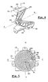
- la figure 3 est une vue agrandie d'un détail de la figure 2 qui représente des éléments dioptriques élémentaires ;
- la figure 4 est une vue en perspective de trois quarts arrière, avec arrachement, qui représente le feu de signalisation de la figure 1 ;
- la figure 5 est une vue de face qui représente le feu de signalisation de la figure 1 ;
- la figure 6 est une vue partielle agrandie en coupe axiale, suivant le plan de coupe 6-6 de la figure 2, qui illustre le trajet des rayons lumineux émis par la diode électroluminescente du feu de signalisation de la figure 1 ;
- la figure 7 est une vue partielle similaire à celle de la figure 6 qui représente une variante de réalisation des éléments dioptriques ;
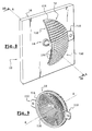
- la figure 8 est une vue en perspective de trois quarts avant, avec arrachement, qui représente un feu de signalisation selon un deuxième mode de réalisation de l'invention ;
- la figure 9 est une vue en perspective de trois quarts arrière qui représente la pièce optique du feu de signalisation de la figure 8 ;
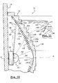
- la figure 10 est une vue partielle agrandie en coupe axiale, suivant le plan de coupe 10-10 de la figure 8, qui illustre le trajet des rayons lumineux émis par la diode électroluminescente du feu de signalisation de la figure 8 ;
- la figure 11 est une vue agrandie d'un détail de la figure 10 qui représente le trajet d'un rayon lumineux dans un dioptre annulaire appartenant à la partie périphérique de la face arrière du feu de signalisation de la figure 8.
- Figure 1 is an exploded perspective view of three quarters before which represents the signal light according to a first embodiment of the invention;
- Figure 2 is a perspective view of three quarters front, with parts broken away, which represents the signaling light of Figure 1;
- Figure 3 is an enlarged view of a detail of Figure 2 which shows elementary dioptric elements;
- Figure 4 is a perspective view of three quarters rear, with cutaway, which shows the signaling light of Figure 1;
- Figure 5 is a front view showing the signal light of Figure 1;
- Figure 6 is an enlarged partial view in axial section, along the section plane 6-6 of Figure 2, which illustrates the path of the light rays emitted by the light emitting diode of the signaling light of Figure 1;
- Figure 7 is a partial view similar to that of Figure 6 which shows an alternative embodiment of the dioptric elements;
- Figure 8 is a perspective view of three quarters front, with cutaway, which shows a signal light according to a second embodiment of the invention;
- Figure 9 is a rear three-quarter perspective view which shows the optical part of the signaling light of Figure 8;
- Figure 10 is an enlarged partial view in axial section, along the section plane 10-10 of Figure 8, which illustrates the path of the light rays emitted by the light emitting diode of the signaling light of Figure 8;
- FIG. 11 is an enlarged view of a detail of FIG. 10 which represents the path of a light ray in an annular diopter belonging to the peripheral part of the rear face of the signaling light of FIG. 8.
Dans la description qui va suivre, des éléments sensiblement identiques ou similaires seront désignés par des références identiques.In the description which follows, elements substantially identical or similar will be designated by identical references.
On a représenté sur les figures 1 à 7 un feu de
signalisation 10 qui est réalisé conformément à un premier mode
de réalisation de l'invention.There is shown in Figures 1 to 7 a
Ce feu de signalisation 10 comporte une pièce optique
pleine 12 qui sert à la fois de récupérateur de flux lumineux et de
diffuseur de flux lumineux pour une source lumineuse constituée
ici d'une diode électroluminescente 14.This signal light 10 comprises an optical part
full 12 which serves as both a luminous flux recuperator and a
light flux diffuser for a constituted light source
here of a
La diode 14 a été représentée montée sur une platine de
support 16 qui permet notamment son raccordement à un réseau
d'alimentation électrique et à une unité de commande (non
représentés).
Avantageusement on utilise une diode 14 dite de forte
puissance, c'est à dire une diode dont la puissance lumineuse est
de plusieurs dizaines de lumens, par exemple supérieure à 30
lumens, ce qui est à comparer avec la puissance inférieure à 10
lumens des diodes dites de faible puissance. Advantageously, a so-called
Les diodes 14 de forte puissance sont disponibles dans
plusieurs couleurs, c'est à dire qu'il est possible de choisir la
coloration du flux lumineux émis par la diode 14. De préférence,
on choisit la couleur de la diode 14 d'après la fonction de
signalisation à réaliser, par exemple le rouge pour une fonction
feu anti-brouillard, ou le blanc pour une fonction feu de recul.The
La pièce optique 12 et la diode 14 sont agencées
coaxialement suivant un axe optique central A-A qui s'étend
globalement horizontalement de la gauche vers la droite, en
considérant la figure 6.The
Dans la suite de la description, on utilisera, à titre non limitatif, une orientation axiale d'arrière en avant qui correspond à une orientation de gauche à droite suivant l'axe optique A-A, en considérant la figure 6.In the following description, we will not use limiting, an axial orientation from back to front which corresponds to an orientation from left to right along the optical axis A-A, in considering figure 6.
A titre non limitatif, on qualifiera des éléments d'extérieurs ou d'intérieurs suivant qu'ils sont agencés radialement vers l'axe optique A-A ou à l'opposé de cet axe.Without limitation, we will qualify elements of exteriors or interiors depending on whether they are arranged radially towards the axis optic A-A or opposite this axis.
En se référant notamment à la figure 1, on constate que la
diode 14 comporte à l'arrière un boítier de connexion 18
sensiblement cylindrique et à l'avant un globe 20 sensiblement
hémisphérique centré sur l'axe optique A-A.Referring in particular to FIG. 1, it can be seen that the
Le boítier de connexion 18 comporte des moyens de
fixation et de raccordement électrique (non représentés) pour le
montage de la diode 14 sur la platine 16.The
La pièce optique 12 est réalisée dans un matériau
transparent présentant un indice de réfraction supérieur à celui de
l'air, qui constitue ici le milieu ambiant entourant la pièce 12.The
Avantageusement, la pièce optique 12 est réalisée en une
seule pièce par moulage dans une matière plastique transparente
telle que, par exemple, du polymétacrylate de méthyle (PMMA).Advantageously, the
Comme on peut le voir notamment sur les vues avec
arrachement des figures 2 et 4, la pièce optique 12 comporte un
corps principal 22 qui a globalement une forme tronconique,
partiellement creuse à l'avant, dont la base forme son extrémité
axiale avant 24 et dont le sommet forme son extrémité axiale
arrière 26.As can be seen in particular on the views with
cutaway of Figures 2 and 4, the
La pièce optique 12 comporte ici trois pattes de fixation 28,
30, 32 qui s'étendent axialement vers l'arrière, à partir de
l'extrémité axiale avant 24 du corps principal 22.The
Ces trois pattes 28, 30, 32 sont ici réparties angulairement
de manière régulière et comportent, à leur extrémité axiale
arrière, une portion d'appui 34 qui s'étend vers l'extérieur dans un
plan sensiblement radial et qui comporte un trou axial 36. Le trou
36 vise à permettre la fixation de la pièce optique 12 sur un
support (non représenté) du feu 10, par un système de fixation de
type connu, par exemple par vissage.These three
Les pattes de fixation 28, 30, 32 servent à maintenir la
pièce optique 12 sur un support du feu 10 et elles doivent retenir
axialement et radialement la pièce optique 12 par rapport à la
source lumineuse, ici la diode 14.The fixing lugs 28, 30, 32 serve to maintain the
La fixation de la pièce optique 12 sur un support ne
nécessite pas forcément que les pattes 28, 30, 32 comportent un
trou 36. En effet, les pattes 28, 30, 32 peuvent être fixées
directement sur le support par sertissage ou soudure aux
ultrasons.The fixing of the
Le corps principal 22 de la pièce optique 12 est ici une
forme de révolution autour de l'axe optique A-A.The
En se référant notamment à la figure 6, on constate que le
corps principal 22 comporte à son extrémité axiale arrière 26 un
tronçon tubulaire 38. Ce tronçon tubulaire 38 forme une entretoise
qui garantit notamment que, lorsque la pièce optique 12 est
montée en appui axial contre la face avant 40 de la platine 16, le
corps principal 22 n'est pas en appui axial contre la diode 14, ce
qui pourrait l'endommager.With particular reference to FIG. 6, it can be seen that the
Le tronçon tubulaire 38 sert aussi à centrer la diode 14,
dans un plan radial, par rapport à la pièce optique 12. A cet effet,
le tronçon tubulaire 38 comporte, par exemple, trois nervures
axiales de centrage 42, ou godrons, sur sa face interne 44, qui
coopèrent avec la paroi cylindrique 46 du boítier de connexion 18
de la diode 14.The
Selon une variante de réalisation (non représentée), le
tronçon tubulaire 38 peut comporter des picots axiaux qui sont
reçus dans des trous complémentaires réalisés en vis-à-vis dans
le support.According to an alternative embodiment (not shown), the
Le corps principal 22 comporte, dans son extrémité axiale
arrière 26, un logement 48 qui est prévu pour recevoir axialement
le globe 20 de la diode 14. Plus précisément, la diode 14 est
agencée dans le logement 48 de manière que son globe 20
s'étende entièrement à l'intérieur du logement 48.The
Sur la figure 6, où le logement 48 est représenté en coupe
axiale, on constate qu'il a globalement une forme cylindrique. Sa
paroi cylindrique 50 délimite, à son extrémité axiale arrière, une
surface d'épaulement 52 avec la paroi cylindrique interne 44 du
tronçon tubulaire 38. Le diamètre interne de la paroi cylindrique
interne 44 est légèrement supérieur au diamètre interne du
logement 48.In Figure 6, where the
L'extrémité axiale avant du logement 48 est fermée par une
paroi 54 convexe (vers l'arrière) qui forme une lentille
convergente centrée sur l'axe optique A-A.The front axial end of the
On décrira maintenant la forme particulière de la face
arrière tronconique 56 et de la face avant tronconique 58 du corps
principal 22 de la pièce optique 12, en se référant notamment à la
figure 6.We will now describe the particular shape of the face
tapered rear 56 and
La face arrière tronconique 56 est étagée radialement vers
l'extérieur et axialement vers l'avant, ici à partir de l'extrémité
axiale avant 60 du tronçon tubulaire 38.The frustoconical
La face arrière tronconique 56 est donc formée par une
série de surfaces tronconiques 62, 64, 66, 68, 70 coaxiales
superposées axialement et reliées entre elles par des surfaces
72, 74, 76, 78 sensiblement radiales et annulaires.The frustoconical
La génératrice de chaque surface tronconique 62, 64, 66,
68, 70 s'étend dans une direction sensiblement inclinée vers
l'avant, c'est à dire de l'arrière vers l'avant et depuis l'axe optique
A-A vers l'extérieur.The generator of each
Le diamètre moyen de chaque surface tronconique 62, 64,
66, 68, 70 est croissant de l'arrière vers l'avant.The average diameter of each
Dans la suite de la description, les surfaces arrière tronconiques 62, 64, 66, 68, 70 seront appelées faces de réflexion.In the following description, the rear surfaces frustoconical 62, 64, 66, 68, 70 will be called faces of reflection.
La face avant tronconique 58 du corps principal 22 est
délimitée axialement à l'arrière par une surface centrale 80
sensiblement radiale et circulaire, qui est agencée axialement en
regard de la lentille 54. Le diamètre de la surface centrale 80 est
ici sensiblement égal au diamètre de la lentille 54.The frustoconical
Depuis la surface centrale 80 jusqu'à l'extrémité axiale
avant 24 de la pièce optique 12, la face avant tronconique 58 est
étagée radialement vers l'extérieur et axialement vers l'avant. La
face avant tronconique 58 est donc formée par une série de
surfaces avant annulaires radiales désignées par les références
82 à 96.From the
Dans la suite de la description, les surfaces avant annulaires 82 à 96 seront appelées faces de sortie.In the following description, the front surfaces annulars 82 to 96 will be called exit faces.
Le bord intérieur de chaque face de sortie 82 à 96 est lié
au bord extérieur de la surface radiale 80 ou de la face de sortie
82 à 96 qui lui est adjacente radialement par une surface
sensiblement cylindrique 98.The inner edge of each outlet face 82 to 96 is linked
at the outer edge of the
Ainsi, vues de face, telles que représentées sur la figure 5, les faces de sortie 82 à 96 forment une série de couronnes adjacentes concentriques.Thus, front views, as shown in FIG. 5, the outlet faces 82 to 96 form a series of crowns concentric adjacent.
Les faces de sortie 82 à 96 ne sont pas planes. Elles sont
formées chacune d'une série d'éléments dioptriques élémentaires
100, ou motifs dioptriques, adjacents.The outlet faces 82 to 96 are not planar. They are
each formed of a series of elementary
Dans le mode de réalisation représenté ici, chaque élément
dioptrique 100 a la forme d'une portion angulaire de couronne, en
considérant la couronne formée par la face de sortie 82 à 96
associée. Les éléments dioptriques 100 d'une face de sortie 82 à
96 déterminée sont donc répartis circonférentiellement de sorte
qu'ils soient adjacents circonférentiellement deux à deux.In the embodiment shown here, each
Comme on l'a représenté sur la vue de détail de la figure
3, chaque élément dioptrique 100 forme une facette bombée, ici
de profil globalement concave vers l'arrière.As shown in the detail view of the figure
3, each
Chaque élément dioptrique 100 est assimilable à un
dioptre, ou prisme. Dans le présent mode de réalisation, chaque
élément dioptrique 100 constitue un dioptre divergent, en raison
de son profil concave.Each
Si l'on considère la variante de réalisation représentée sur
la figure 7, qui est une vue partielle en coupe axiale d'une pièce
optique 12 conforme aux enseignements de l'invention, on
remarque que chaque élément dioptrique 100 peut être convexe
(vers l'avant), de manière à former un dioptre convergent.If we consider the variant shown on
Figure 7, which is a partial view in axial section of a
Conformément aux enseignements de l'invention, la forme
concave, ou galbe, de la surface formant chaque élément
dioptrique 100 est déterminé de manière que des rayons
lumineux, dirigés vers l'avant, qui atteignent la face arrière 102
de l'élément dioptrique 100 suivant une direction sensiblement
parallèle à l'axe optique A-A, ressortent par la face avant 104 de
l'élément dioptrique 100 en formant à l'avant un faisceau
d'éclairage réalisant la fonction de signalisation choisie.In accordance with the teachings of the invention, the form
concave, or curve, of the surface forming each
Par exemple, si le feu de signalisation 10 est prévu pour
réaliser une fonction de feu anti-brouillard, alors chaque élément
dioptrique 100 dévie et répartit les rayons lumineux qu'il reçoit de
manière à réaliser à l'avant, sur un écran de mesure, une image
globalement en forme de losangeFor example, if the
Le losange n'est pas régulier. Il doit avoir une hauteur,
suivant l'axe vertical V-V, inférieure à sa largeur, suivant l'axe
horizontal H-H. Donc, suivant l'orientation angulaire de chaque
élément dioptrique 100, dans un plan radial, sa forme concave
doit être optimisée pour permettre de réaliser sur l'écran de
mesure une forme qui se rapproche du losange recherché ici. The diamond is not regular. It must have a height,
along the vertical axis V-V, less than its width, along the axis
horizontal H-H. So, according to the angular orientation of each
Des algorithmes mathématiques permettent de calculer,
par « morphing » progressif, la forme appropriée pour chaque
élément dioptrique 100, en fonction de sa position angulaire
autour de l'axe optique A-A.Mathematical algorithms allow to calculate,
by progressive "morphing", the appropriate form for each
On note que les éléments dioptriques 100 appartenant à
des faces de sortie 82 à 96 différentes, et dont la position
angulaire par rapport à l'axe optique A-A est sensiblement
identique, ont globalement la même forme concave.It is noted that the
La surface centrale 80 est elle aussi formée d'une série
d'éléments dioptriques 100, ici agencés globalement dans le
même plan radial.The
A la différence des faces de sortie 82 à 96, les éléments
dioptriques 100 formant la surface centrale 80 sont agencés
suivant un maillage rectangulaire, ici parallèle à l'axe vertical V-V.Unlike the outlet faces 82 to 96, the
On note que les éléments dioptriques 100 de la surface
centrale 80 qui sont adjacents à son bord circulaire 81 sont des
portions de rectangle qui comportent un bord en arc de cercle.It is noted that the
On expliquera maintenant le fonctionnement du feu de
signalisation 10 selon l'invention, notamment au regard de la
figure 6, qui illustre schématiquement la trajectoire des rayons
lumineux émis par la diode 14.We will now explain the operation of the
signaling 10 according to the invention, in particular with regard to the
Figure 6, which schematically illustrates the trajectory of the rays
light emitted by the
L'ensemble du système optique constitué par la diode 14 et
la pièce optique 12 étant globalement de révolution autour de
l'axe optique A-A, on expliquera le fonctionnement optique
uniquement dans le demi-plan axial qui est représenté sur la
figure 6.The entire optical system constituted by the
Pour faciliter la compréhension de l'invention, seule une
partie des rayons lumineux émis par la diode 14 ont été
représentés sur la figure 6.To facilitate understanding of the invention, only one
part of the light rays emitted by
En considérant de manière approximative que la diode 14
est une source lumineuse ponctuelle, agencée sur l'axe optique
A-A, on suppose que les rayons lumineux sont émis radialement,
globalement vers l'avant, depuis le centre 106 de l'hémisphère
formant le globe 20.Considering roughly that the
On note que, la diode 14 étant du type à forte puissance,
elle a une ouverture proche de 180 degrés, c'est à dire qu'elle
émet des rayons lumineux suivant un angle solide de 180 degrés.We note that, the
Parmi les rayons lumineux émis par la diode 14, on
constate qu'une majeure partie de ces rayons impacte sur la paroi
cylindrique 50 du logement 48.Among the light rays emitted by the
Etant donné l'angle d'incidence de ces rayons lumineux sur
la paroi cylindrique 50, on considère que la majeure partie du flux
lumineux formé par ces rayons pénètre à l'intérieur du corps 22
de la pièce optique 12 en se réfractant, selon les lois optiques
classiques.Given the angle of incidence of these light rays on
the
Bien entendu, plus les rayons lumineux émis sont proches de la direction verticale, en considérant la figure 6, moins ils sont réfractés.Of course, the closer the light rays emitted of the vertical direction, considering figure 6, the less they are refracted.
Par exemple, en admettant que la diode 14 émette un
rayon R1 verticalement vers le haut, depuis son centre 106, donc
perpendiculairement à la paroi cylindrique 50, alors ce rayon R1
pénètre dans le corps 22 sans déviation.For example, assuming that the
On note que, pour que la pièce optique 12 exploite la
majorité du flux lumineux émis par la diode 14, il importe que la
face de réflexion 62, la plus proche de l'axe optique A-A, s'étende
axialement en arrière du centre 106 de la diode 14, de sorte que
le rayon R1, qui est le rayon le plus à l'arrière, soit réfléchi vers
l'avant par ladite face de réflexion 62. Dans le cas contraire, le
rayon R1, et des rayons lumineux voisins, seraient « perdus » à
l'intérieur du corps 22, par exemple en se réfractant vers la paroi
externe du tronçon tubulaire 38.Note that, for the
Après avoir traversé la paroi cylindrique 50 du logement,
les rayons lumineux sont réfractés de sorte qu'ils « impactent »
contre une face de réflexion 62 à 70 du corps 22 de la pièce
optique 22. En arrivant sur les faces de réflexion 62 à 70, ces
rayons lumineux sont totalement réfléchis vers l'avant,
conformément au principe optique de la réflexion totale de la
lumière dans un milieu d'indice de réfraction supérieur à celui de
l'air. Ainsi, lorsqu'un rayon lumineux « impacte » sur une face de
réflexion 62 à 70 du corps 22, avec un angle d'incidence
suffisamment éloigné d'une direction orthogonale, alors il est
totalement réfléchi par ladite face de réflexion 62 à 70, sans qu'il
soit nécessaire par exemple de déposer un matériau réfléchissant
sur ladite face 62 à 70.After passing through the
L'inclinaison de la génératrice de chaque face de réflexion 62 à 70 est prévue pour que les rayons lumineux qu'elle reçoit soient réfléchis vers l'avant, suivant une direction globalement parallèle à l'axe optique A-A.The inclination of the generator of each reflection face 62 to 70 is provided so that the light rays it receives are reflected forward, in a generally direction parallel to the optical axis A-A.
A cet effet, l'angle d'inclinaison des génératrices des faces
de réflexion 62 à 70 par rapport à l'axe optique A-A, dans le sens
horaire en considérant la figure 6, tend à diminuer lorsque l'on
s'écarte de l'axe optique A-A, radialement vers l'extérieur.For this purpose, the angle of inclination of the generatrices of the
Avantageusement, la génératrice de chaque face de
réflexion 62 à 70 est légèrement en courbe convexe, de manière à
s'adapter progressivement à l'angle d'incidence des rayons
réfractés qui évolue suivant la position axiale de son lieu
d'incidence sur la paroi cylindrique 50.Advantageously, the generator of each face of
Les rayons réfléchis sur les faces de réflexion 62 à 70 sont
donc dirigés vers l'avant, suivant des directions globalement
parallèles à l'axe optique A-A, sur la face arrière 102 des
éléments dioptriques 100 formant les faces de sortie 82 à 96.The rays reflected on the reflection faces 62 to 70 are
therefore directed forwards, following directions generally
parallel to the optical axis A-A, on the
Les éléments dioptriques 100 dévient les rayons lumineux
de manière que le faisceau lumineux émis vers l'avant à partir de
chaque élément dioptrique 100 forme globalement un losange,
dans le cas d'un feu anti-brouillard.The
Sur la figure 6, le trajet des rayons lumineux qui vient d'être décrit, est illustré par le faisceau F1 et par le faisceau F2.In FIG. 6, the path of the light rays which comes to be described, is illustrated by the beam F1 and by the beam F2.
On note que les surfaces radiales annulaires 72, 74, 76, 78
sont des surfaces neutres optiquement, vis-à-vis de la
transmission des rayons lumineux à l'intérieur de la pièce optique
12. En effet, les rayons lumineux qui sont réfractés à l'intérieur du
corps 22, à travers la paroi cylindrique 50, du fait de leurs
inclinaisons, ne peuvent pas atteindre ces surfaces radiales
annulaires 72, 74, 76, 78.Note that the annular radial surfaces 72, 74, 76, 78
are optically neutral surfaces, vis-à-vis the
transmission of light rays inside the
Les surfaces radiales annulaires 72, 74, 76, 78 ne sont pas
indispensables, car la face arrière tronconique 56 peut ne pas
être étagée et ne former ainsi qu'une seule face arrière de
réflexion.The annular radial surfaces 72, 74, 76, 78 are not
essential, because the frusto-conical
Toutefois, l'étagement des faces de réflexion 62 à 70
permet d'augmenter le diamètre extérieur de la pièce optique 12,
donc la surface lumineuse apparente qui réalise la fonction de
signalisation.However, the staging of the reflection faces 62 to 70
increases the outside diameter of the
En effet, lorsque l'on réalise une fonction de signalisation,
contrairement à une fonction d'éclairage avant, les personnes des
véhicules qui suivent le véhicule équipé d'un feu de signalisation
10 selon l'invention sont souvent amenées à porter leur regard en
direction de la source lumineuse. Il importe donc de minimiser la
luminance du feu 10 par unité de surface, en vue d'éviter
l'éblouissement desdites personnes.Indeed, when we carry out a signaling function,
unlike a front lighting function, people of
vehicles following the vehicle equipped with a signaling
De préférence, le rayon lumineux R2, qui traverse la paroi
cylindrique 50 du logement 48 au voisinage de son extrémité
axiale avant 108, et qui constitue approximativement le
« dernier » rayon lumineux, en partant de l'arrière, à traverser la
paroi cylindrique 50, détermine l'épaisseur axiale minimale du
corps 22 de la pièce optique 12 et son diamètre externe.Preferably, the light ray R2, which passes through the wall
cylindrical 50 of the
En effet, ce rayon lumineux R2, lorsqu'il se réfracte à
l'intérieur du corps 22, est situé le plus à l'avant. Par conséquent,
il est préférable que les faces de sortie 82 à 96 soient agencées
axialement à l'avant de ce rayon R2, de manière qu'elles ne
soient pas interposées entre le rayon R2 et la face de réflexion 70
sur laquelle il est prévu qu'il se réfléchisse. La position axiale des
faces de sortie 82 à 96 détermine en partie l'épaisseur axiale du
corps 22. Indeed, this light ray R2, when it refracts to
the interior of the
De plus, le rayon R2 se réfléchit sur la face de réflexion 70
radialement la plus extérieure et axialement la plus à l'avant. Par
conséquent, le rayon R2 détermine la position axiale et la position
radiale de l'extrémité axiale avant 24 de la face de réflexion
radialement extérieure 70, donc le diamètre externe et la
profondeur axiale du corps 22 de la pièce optique 12.In addition, the radius R2 is reflected on the
Dans le mode de réalisation représenté ici, on a laissé une marge axiale entre le rayon R2 et les faces de sortie 82 à 96.In the embodiment shown here, a axial margin between the radius R2 and the outlet faces 82 to 96.
Une partie des rayons lumineux émis par la diode 14, ceux
qui ont une inclinaison plus faible par rapport à l'axe optique A-A,
impactent sur la lentille 54.Part of the light rays emitted by
Cette lentille 54 forme ici une lentille convergente qui
permet de dévier les rayons lumineux entrant sur sa face arrière
de manière qu'ils se réfractent à l'intérieur du corps 22 de la
pièce optique 12 suivant une direction globalement parallèle à
l'axe optique A-A.This
Ces rayons lumineux arrivent donc sur les faces arrière
102 des éléments dioptriques 100 de la surface centrale 80,
parallèlement à l'axe optique A-A, et les éléments dioptriques 100
répartissent spatialement les rayons lumineux de manière à
former une image similaire à celle formée par les éléments
dioptriques 100 des faces de sortie 82 à 96.These light rays therefore arrive on the rear faces
102 of the
Sur la figure 6, le trajet des rayons lumineux qui pénètrent
dans le corps 22 de la pièce optique 12 par la lentille 54, est
illustré par le faisceau F3.In FIG. 6, the path of the light rays which penetrate
in the
Le flux lumineux produit à la sortie de la pièce optique 12
par les faisceau F1 et F2 peut être appelé flux réfléchi, car ses
rayons lumineux ont subi une réflexion sur les faces de réflexion
62 à 70 de la pièce optique 12.The luminous flux produced at the exit of the
Le flux lumineux produit à la sortie de la pièce optique 12
par le faisceau F3 peut être appelé flux direct, car ses rayons
lumineux n'ont pas subi de réflexion à l'intérieur de la pièce
optique 12. The luminous flux produced at the exit of the
La paroi cylindrique 48 du logement 50, les faces arrière
de réflexion 62 à 70, et la lentille 54 forment un récupérateur de
flux lumineux.The
Les faces avant de sortie 80 à 96 forment un répartiteur de flux lumineux.The outlet front faces 80 to 96 form a distributor luminous flow.
On note que le feu de signalisation 10 selon l'invention
permet d'optimiser l'emploi des nouvelles diodes de forte
puissance. En effet, la pièce optique 12 selon l'invention permet
de récupérer la majorité du flux lumineux émis par la diode 14, de
sorte que la diode 14 et la pièce optique 12 suffisent à satisfaire
les exigences photométriques pour réaliser une fonction de
signalisation réglementaire, alors qu'auparavant il était
nécessaire d'utiliser plusieurs diodes, afin d'obtenir à la sortie du
feu de signalisation une énergie lumineuse suffisante.It is noted that the signaling
Le feu de signalisation 10 selon l'invention permet donc de
réaliser une fonction de signalisation réglementaire avec un feu
de taille inférieure, ce qui facilite notamment l'agencement du feu
dans un véhicule.The signaling
Toutefois, selon des variantes de réalisation (non
représentées) de l'invention, on peut réaliser une fonction de
signalisation déterminée à l'aide de plusieurs pièces optiques 12
et de plusieurs diodes de faible puissance associées.However, according to variant embodiments (not
shown) of the invention, a function of
signaling determined using several
Selon une autre variante de réalisation (non représentée)
de l'invention, on peut remplacer la diode 14 par une lampe à
filament. Cependant, cette variante nécessite d'augmenter de
manière importante la taille de la pièce optique 12, notamment
pour permettre l'évacuation de la chaleur produite par le filament.
De plus, une grande partie du flux lumineux émis par la lampe à
filament ne pourra pas être récupéré par la pièce optique, sans
ajout d'un dispositif de récupération supplémentaire.According to another alternative embodiment (not shown)
of the invention, the
Selon encore une variante de réalisation (non représentée)
de l'invention, les faces avant de sortie 82 à 96 ne sont pas
étagées, c'est à dire que le corps 22 de la pièce optique 12
comporte une seule face de sortie qui forme une surface radiale
ronde agencée à l'extrémité axiale avant 24 de la pièce optique
12.According to another variant embodiment (not shown)
of the invention, the outlet front faces 82 to 96 are not
stepped, that is to say that the
Les éléments dioptriques 100 sont alors tous agencés
globalement dans le même plan radial. Ces éléments dioptriques
100 peuvent conserver le même agencement que dans le mode de
réalisation décrit précédemment, de sorte que l'aspect de la pièce
optique 12 en vue avant soit le même que sur la figure 5, ou bien
les éléments dioptriques 100 peuvent tous être agencés suivant
un maillage rectangulaire.The
Toutefois, on note que l'étagement des faces avant de
sortie 82 à 96, conformément au mode de réalisation décrit en
référence aux figures 1 à 7, permet de minimiser l'épaisseur
axiale moyenne de la pièce optique 12. Cette caractéristique est
facilite la réalisation de la pièce optique 12 en moulage par
injection de matière, en particulier parce qu'elle diminue la
quantité de matière nécessaire à la réalisation de la pièce optique
12.However, we note that the staging of the front faces of
On a représenté, sur les figures 8 à 11, un deuxième mode de réalisation d'un feu de signalisation 10 réalisé conformément aux enseignements de l'invention.There is shown, in Figures 8 to 11, a second mode for producing a signaling light 10 produced in accordance with to the teachings of the invention.
Le feu de signalisation 10 comporte, comme dans le
premier mode de réalisation, une diode électroluminescente 14 de
forte puissance qui est montée sur une platine de support 16, et
une pièce optique 12 qui est montée sur un support (non
représenté) du feu de signalisation 10, à l'avant de la diode 14.The signaling
Comme on peut le voir, notamment sur la figure 9, la pièce
optique 12 a globalement une forme de révolution autour de l'axe
optique A-A sur lequel est agencé la diode 14.As can be seen, in particular in FIG. 9, the
La pièce optique 12 a globalement la forme d'une calotte
sphérique qui est évidée à l'arrière et qui comporte ici deux pattes
de support 110, 112, diamétralement opposées, s'étendant dans
un plan radial à partir de l'extrémité axiale arrière 114 de la pièce
optique 12. The
Les pattes de support 110, 112 sont par exemple similaires
aux portions d'appui 34 des pattes 28, 30, 32 de la pièce optique
12 du premier mode de réalisation.The
La face arrière concave (vers l'avant) 116 de la pièce
optique 12 a la forme d'un récupérateur de flux du type à optique
de Fresnel, bien connu de l'état de la technique. Pour plus de
précisions, on pourra se reporter notamment au document FR-A-2.507.741,
qui décrit un récupérateur de flux de ce type.The concave rear face (forward) 116 of the
La face arrière 116 a donc la forme d'une lentille de
Fresnel, ou lentille à échelons.The
Comme on peut le voir, notamment sur la figure 10, la face
arrière 116 comporte ici une partie centrale 118 qui est constituée
d'une série de dioptres annulaires convergents 120.As can be seen, especially in Figure 10, the face
rear 116 here comprises a
Les dioptres convergents 120 de la partie centrale 118
sont étagés radialement vers l'extérieur et axialement vers
l'arrière.The converging
Ils collectent les rayons lumineux émis par la diode 14
selon un angle solide, centré sur l'axe optique A-A, ayant une
faible ouverture, par exemple d'environ 60 degrés.They collect the light rays emitted by the
La partie centrale 118 est prévue pour fonctionner en
simple réfraction, c'est à dire que les rayons lumineux qu'elle
reçoit se réfractent à l'intérieur de la pièce optique 12 et sont
déviés suivant une direction sensiblement parallèle à l'axe
optique A-A.The
La partie centrale 118 a ici un diamètre sensiblement égal
au diamètre du boítier de connexion 18 de la diode 14.The
La face arrière 116 comporte une partie périphérique
annulaire 122 qui est constitué d'une série de dioptres, ou
prismes, annulaires 124.The
Ces dioptres annulaires 124 forment un profil en dents de
scie sur la face arrière 116.These
Comme on peut le voir, notamment sur la figure 11, chaque
dioptre annulaire 124 comporte une face intérieure d'entrée 126,
dont la génératrice s'étend dans une direction sensiblement
parallèle à l'axe optique A-A, et une face extérieure de réflexion
128, dont la génératrice s'étend dans une direction sensiblement
inclinée vers l'avant, depuis l'extrémité axiale arrière 130 de la
face d'entrée 126.As can be seen, especially in Figure 11, each
De préférence, l'angle d'inclinaison des faces de réflexion
128, par rapport à l'axe optique A-A, augmente depuis les
dioptres annulaires 124 proches de l'axe A-A vers les dioptres
annulaires 124 éloignés de l'axe A-A, de manière que l'inclinaison
des faces de réflexion 128 s'adapte à l'angle d'incidence des
rayons lumineux qu'ils reçoivent en provenance de la diode 14.Preferably, the angle of inclination of the reflection faces
128, with respect to the optical axis A-A, increases since the
La partie périphérique 122 est prévue pour fonctionner à la
fois en réfraction, en collectant les rayons lumineux qui se
réfractent sur les faces d'entrée 126 de ses dioptres annulaires
124, et en réflexion, en déviant les rayons lumineux suivant une
direction sensiblement parallèle à l'axe optique A-A, après qu'ils
se soient réfléchis sur les faces de réflexion 128 de ses dioptres
annulaires 124.The
Conformément aux enseignements de l'invention, la face
avant de sortie 132 de la pièce optique 12 est formée par une
série d'éléments dioptriques élémentaires de répartition 100. Ces
éléments dioptriques 100 sont similaires à ceux qui ont été décrits
en référence au premier mode de réalisation.In accordance with the teachings of the invention, the face
before
Chacun des éléments dioptriques 100 a ici une surface
avant 104 convexe, de manière à former un dioptre convergent,
comme dans la variante de réalisation représentée sur la figure 7.Each of the
Les éléments dioptriques 100 ont ici une forme
sensiblement carrée (en vue de face)The
Comme on peut le voir sur la figure 8, les éléments dioptriques 100 forment ici un maillage rectangulaire.As can be seen in Figure 8, the elements dioptrics 100 here form a rectangular mesh.
Selon une variante de réalisation (non représentée) de
l'invention, les éléments dioptriques 100 peuvent être agencés en
couronnes comme dans le premier mode de réalisation.According to an alternative embodiment (not shown) of
the invention, the
Les éléments dioptriques 100 sont ici étagés radialement
vers l'extérieur et axialement vers l'arrière, formant ainsi des
escaliers qui descendent depuis l'axe optique A-A vers l'extérieur
et vers l'arrière.The
Chaque élément dioptrique 100 est donc lié à l'élément
dioptrique 100 qui lui est radialement adjacent par une surface
134, ici sensiblement parallèle à l'axe A-A.Each
Selon une autre variante de réalisation (non représentée)
de l'invention, la face avant 132 de la pièce optique 12 peut être
globalement plane, de sorte que tous les éléments dioptriques
100 soient contenus globalement dans un même plan radial.
Selon cette variante, la pièce optique 12 a alors une forme
globalement cylindrique, avec une face avant de sortie 132
radiale et une face arrière concave 116, en forme de calotte
sphérique.According to another alternative embodiment (not shown)
of the invention, the
On note que, dans le mode de réalisation représenté ici,
les éléments dioptriques 100, qui sont agencés axialement en
regard de la partie centrale 118, sont contenus globalement dans
un même plan radial et ils forment ainsi une face avant centrale
de sortie 80.Note that, in the embodiment shown here,
the
Grâce à la forme de calotte sphérique de la pièce optique
12, celle-ci entoure et recouvre sensiblement la totalité du globe
20 de la diode 14, de sorte que tous les rayons lumineux émis par
la diode 14 sont récupérés par la face arrière 116 de la pièce
optique 12.Thanks to the spherical cap shape of the
Le fonctionnement du feu de signalisation 10 suivant le
deuxième mode de réalisation de l'invention est similaire à celui
qui a été décrit dans le cadre du premier mode de réalisation.The operation of the signaling
Les rayons lumineux émis par la diode 14 sur la face
arrière de la partie centrale 118, par exemple les rayons R3 et
R4, se réfractent à l'intérieur de la pièce optique 12 en suivant
une direction sensiblement parallèle à l'axe optique A-A. Puis ils
atteignent les faces arrière 102 des éléments dioptriques 100 en
vis-à-vis qui les répartissent à l'avant du feu de signalisation 10,
de manière à réaliser la fonction de signalisation désirée. The light rays emitted by
Chacun des rayons lumineux R5, R6, R7, R8, émis par la
diode 14 sur la face arrière de la partie périphérique 122, par
exemple le rayon R8 qui est représenté en détail sur la figure 11,
va d'abord se réfracter à l'intérieur de la pièce optique 12, en
traversant la face d'entrée 126 d'un dioptre annulaire 124, puis il
va se réfléchir sur la face de réflexion 128 associée du dioptre
annulaire 124, en restant à l'intérieur de la pièce optique 12, de
manière être dévié vers l'avant, suivant une direction
sensiblement parallèle à l'axe optique A-A. Il atteint ensuite la
face arrière 102 d'un élément dioptrique 100 en vis-à-vis qui le
réparti à l'avant du feu de signalisation 10, de manière à réaliser
la fonction de signalisation désirée.Each of the light rays R5, R6, R7, R8, emitted by the
Selon une variante de réalisation (non représentée) de
l'invention, ce deuxième mode de réalisation est apte à
fonctionner avec une lampe à filament en remplacement de la
diode 14, sous réserve d'augmenter les dimensions de la pièce
optique 12. De préférence, les dimensions de la pièce optique 12
selon la variante sont obtenues par une transformation
homothétique dont le rapport est lié aux différences physiques
des sources lumineuses, en particulier pour assurer le
refroidissement de la lampe à filament.According to an alternative embodiment (not shown) of
the invention, this second embodiment is suitable for
operate with a filament lamp to replace the
Par exemple, l'homothétie est réalisée par rapport au
centre de la source lumineuse, c'est à dire par rapport au filament
pour la lampe à filament et par rapport au centre 106 du globe 20
pour la diode 14, et le coefficient de la matrice de transformation
retenu est trois, pour le passage de la diode 14 vers la lampe à
filament.For example, the homothety is performed in relation to the
center of the light source, i.e. relative to the filament
for the filament lamp and relative to the center 106 of the
On note que, pour les deux modes de réalisation décrits
précédemment, la forme circulaire de révolution de la pièce
optique 12 est la forme optimale qui permet de récupérer la
majorité du flux lumineux émis par la diode 14.It is noted that, for the two embodiments described
previously, the circular shape of revolution of the
D'autres formes peuvent néanmoins être utilisées pour la
pièce optique 12, par exemple une forme en ellipse ou une forme
rectangulaire, en vue de face ou en vue arrière. Other forms can nevertheless be used for the
Dans le feu de signalisation 10 selon l'invention, la pièce
optique 12 est « autonome » au niveau optique, c'est à dire
qu'elle réalise la fonction de signalisation toute seule, sans qu'il
soit nécessaire d'ajouter un réflecteur et/ou une glace de
diffusion. La pièce optique 12 selon l'invention réalise à la fois la
récupération des rayons lumineux émis par la source 14 et la
répartition des rayons lumineux à l'avant de manière à réaliser la
fonction de signalisation choisie.In the
Bien entendu, le feu de signalisation 10 selon l'invention
peut être agencé à l'intérieur d'un boítier comportant une glace de
protection extérieure, par exemple dans un boítier qui regroupe
tous les feux de signalisation associés aux différentes fonctions
réglementaires.Of course, the signaling
Claims (13)
caractérisé en ce que la face de sortie (82, 84, 86, 88, 90, 92, 94, 96, 132) est formée d'une série d'éléments dioptriques élémentaires de répartition (100) dont chacun est prévu pour former un faisceau lumineux élémentaire dont l'image, sur un écran placé à l'avant du feu de signalisation (10), correspond à la fonction de signalisation à réaliser.Signaling light (10), in particular for a motor vehicle, of the type comprising a central optical axis (AA) oriented from the rear towards the front, a generally punctual light source (14) disposed on this optical axis (AA), and a solid optical part (12), at least partly of revolution around the optical axis (AA), which is made of a transparent material with a refractive index higher than that of air, and which is arranged at the front of the source (14), of the type in which the optical part (12) comprises at least:
characterized in that the exit face (82, 84, 86, 88, 90, 92, 94, 96, 132) is formed by a series of elementary distribution dioptric elements (100) each of which is intended to form a elementary light beam whose image, on a screen placed in front of the traffic light (10), corresponds to the signaling function to be performed.
Applications Claiming Priority (2)
| Application Number | Priority Date | Filing Date | Title |
|---|---|---|---|
| FR0202220A FR2836208B1 (en) | 2002-02-21 | 2002-02-21 | SIGNALING LIGHT COMPRISING AN OPTICAL PART PROVIDING AN AUTONOMOUS SIGNALING FUNCTION |
| FR0202220 | 2002-02-21 |
Publications (2)
| Publication Number | Publication Date |
|---|---|
| EP1338844A1 true EP1338844A1 (en) | 2003-08-27 |
| EP1338844B1 EP1338844B1 (en) | 2020-03-11 |
Family
ID=27636396
Family Applications (1)
| Application Number | Title | Priority Date | Filing Date |
|---|---|---|---|
| EP03290318.9A Expired - Lifetime EP1338844B1 (en) | 2002-02-21 | 2003-02-07 | Signal lamp for vehicle comprising an optical element which performs autonomously a signal function |
Country Status (4)
| Country | Link |
|---|---|
| US (1) | US6755556B2 (en) |
| EP (1) | EP1338844B1 (en) |
| JP (1) | JP2003281907A (en) |
| FR (1) | FR2836208B1 (en) |
Cited By (11)
| Publication number | Priority date | Publication date | Assignee | Title |
|---|---|---|---|---|
| FR2859423A1 (en) * | 2003-09-05 | 2005-03-11 | Valeo Systemes Dessuyage | Equipment module for motor vehicle, has signal light including central optical axis, and LED arranged on optical axis and around optical unit which conforms luminous flux generated by LED around optical axis |
| FR2867257A1 (en) * | 2004-03-05 | 2005-09-09 | Valeo Vision | Lighting and/or signalling device for motor vehicle, has dioptric unit whose rear side is divided into angular sectors, where each sector is limited towards back side by elementary rotational surface |
| WO2009141762A1 (en) * | 2008-05-20 | 2009-11-26 | Koninklijke Philips Electronics N.V. | Optical element for asymmetric light distribution |
| WO2010006971A1 (en) * | 2008-07-16 | 2010-01-21 | Osram Gesellschaft mit beschränkter Haftung | Retaining frame comprising at least one optical element |
| DE202010006097U1 (en) | 2009-12-22 | 2010-08-05 | Automotive Lighting Reutlingen Gmbh | Light module for a motor vehicle headlight |
| EP2587120A1 (en) * | 2011-10-27 | 2013-05-01 | odelo GmbH | Light guide and automotive vehicle equipped with such a light guide |
| WO2013054220A3 (en) * | 2011-10-11 | 2013-06-13 | Koninklijke Philips Electronics N.V. | Lighting apparatus |
| WO2014022033A1 (en) * | 2012-08-03 | 2014-02-06 | GE Lighting Solutions, LLC | Omni-directional reflector comprising a frusto-conical surface for a|light-emitting diode |
| EP2713095A3 (en) * | 2012-09-26 | 2017-11-15 | Coretronic Corporation | Vehicle illumination apparatus |
| FR3051413A1 (en) * | 2016-05-19 | 2017-11-24 | Valeo Vision | METHOD FOR CALIBRATING A LIGHT DEVICE |
| EP3835650A1 (en) * | 2019-12-09 | 2021-06-16 | ZKW Group GmbH | Optical body for a motor vehicle headlight |
Families Citing this family (137)
| Publication number | Priority date | Publication date | Assignee | Title |
|---|---|---|---|---|
| DE10249113B4 (en) * | 2002-10-22 | 2010-04-08 | Odelo Gmbh | Vehicle lamp, in particular tail lamp, preferably for motor vehicles |
| JP4182783B2 (en) * | 2003-03-14 | 2008-11-19 | 豊田合成株式会社 | LED package |
| FR2853392B1 (en) * | 2003-04-04 | 2006-06-16 | Sli Miniature Lighting Sa | REAR LIGHT, ESPECIALLY STOP LIGHT FOR MOTOR VEHICLE |
| US8075147B2 (en) * | 2003-05-13 | 2011-12-13 | Light Prescriptions Innovators, Llc | Optical device for LED-based lamp |
| US7329029B2 (en) * | 2003-05-13 | 2008-02-12 | Light Prescriptions Innovators, Llc | Optical device for LED-based lamp |
| DE10329185A1 (en) * | 2003-06-27 | 2005-01-20 | Guido Kellermann Produktentwicklung & Handel | Light for a vehicle |
| US20050007346A1 (en) * | 2003-07-11 | 2005-01-13 | Guolin Ma | Optical conduit for channeling light onto a surface |
| DE10340040A1 (en) * | 2003-08-28 | 2005-03-31 | Schefenacker Vision Systems Germany Gmbh & Co. Kg | Lighting unit with light guide and integrated optical lens |
| US7344266B2 (en) * | 2003-11-03 | 2008-03-18 | Perry Coman | Portable radial projection light source arrangement |
| JP4534074B2 (en) * | 2003-11-27 | 2010-09-01 | 青木電器工業株式会社 | High brightness LED light emitting part |
| DE602004024710D1 (en) * | 2003-12-10 | 2010-01-28 | Okaya Electric Industry Co | INDICATOR LIGHT |
| FR2864204B1 (en) * | 2003-12-19 | 2006-10-27 | Valeo Vision | SIGNALING OR LIGHTING DEVICE, IN PARTICULAR FOR MOTOR VEHICLE |
| JP4497348B2 (en) * | 2004-01-13 | 2010-07-07 | 株式会社小糸製作所 | Vehicle lighting |
| FR2870083B1 (en) | 2004-05-10 | 2006-07-14 | Sli Miniature Lighting Sa Sa | DEVICE FOR HOLDING AND CONNECTING OPTOELECTRONIC COMPONENTS SUCH AS LEDS OF THE PLCC2 AND PLCC4 TYPE |
| FR2870323B1 (en) * | 2004-05-13 | 2006-08-04 | Valeo Vision Sa | ILLUMINATING OR SIGNALING DEVICE HAVING AN OPTICAL PART WHICH REALIZES A REGULAR BEAM IN AN AUTONOMOUS MANNER |
| DE102004026530B3 (en) * | 2004-05-29 | 2006-02-02 | Fer Fahrzeugelektrik Gmbh | optical body |
| ES1058053Y (en) * | 2004-07-14 | 2005-02-01 | Fed Signal Vama Sa | INTERNAL REFLECTION COLIMATOR LENS |
| US20060039160A1 (en) * | 2004-08-23 | 2006-02-23 | Cassarly William J | Lighting systems for producing different beam patterns |
| DE102004042125B4 (en) * | 2004-08-30 | 2008-05-08 | Schefenacker Vision Systems Germany Gmbh & Co. Kg | Lighting unit with a large number of curved surface elements |
| US7168839B2 (en) * | 2004-09-20 | 2007-01-30 | Visteon Global Technologies, Inc. | LED bulb |
| KR101214934B1 (en) * | 2005-01-27 | 2012-12-24 | 삼성디스플레이 주식회사 | Optical lens and optical module having the optical lens and back light assembly having the optical module, and the display apparatus having the back light assembly |
| ATE453930T1 (en) * | 2004-10-14 | 2010-01-15 | Fiat Ricerche | OPTICAL ELEMENT AND MODULE FOR PROJECTING A BUNDLE OF LIGHTS, AND MOTOR VEHICLE LAMP HAVING A PLURALITY OF SUCH MODULES |
| FR2878020B1 (en) * | 2004-11-18 | 2008-12-19 | Valeo Vision Sa | LIGHTING AND / OR SIGNALING DEVICE FOR A MOTOR VEHICLE PRODUCING A BEAM ON THE SIDE OF A MOTOR VEHICLE |
| CA2589121C (en) * | 2004-12-03 | 2010-08-10 | Acuity Brands, Inc. | Luminaire reflector with light-modifying flange |
| TWM275418U (en) * | 2004-12-03 | 2005-09-11 | Chip Hope Co Ltd | Lens with light uniformization |
| KR101119193B1 (en) | 2004-12-30 | 2012-03-22 | 삼성전자주식회사 | Light source unit and liquid crystal display device having the same |
| US7275849B2 (en) * | 2005-02-25 | 2007-10-02 | Visteon Global Technologies, Inc. | LED replacement bulb |
| JP2006243603A (en) * | 2005-03-07 | 2006-09-14 | Sanyo Electric Co Ltd | Condensing element, lighting device, and projection image display device |
| WO2006109113A2 (en) * | 2005-04-12 | 2006-10-19 | Acol Technologies Sa | Primary optic for a light emitting diode |
| US7588358B1 (en) * | 2005-05-31 | 2009-09-15 | Innovative Lighting, Inc | Single LED and lens assembly |
| JP2006339320A (en) * | 2005-05-31 | 2006-12-14 | Omron Corp | Luminescence optical source and outgoing method of light therein |
| CN101238325B (en) | 2005-06-01 | 2011-03-30 | Ccs株式会社 | Light irradiation device |
| FR2887997B1 (en) * | 2005-06-30 | 2008-04-11 | Valeo Vision Sa | OPTICAL GUIDE BIT WITH BRIGHTNESS RADIATION |
| DE102005031777B4 (en) * | 2005-07-07 | 2021-03-11 | HELLA GmbH & Co. KGaA | Signal light for vehicles with a curved optical element that has offset prisms |
| KR20070013469A (en) * | 2005-07-26 | 2007-01-31 | 삼성전자주식회사 | Optical lens and optical package, and backlight assembly and display device having the same |
| US7207700B2 (en) * | 2005-09-22 | 2007-04-24 | Visteon Global Technologies, Inc. | Near field lens with spread characteristics |
| US7401948B2 (en) * | 2005-10-17 | 2008-07-22 | Visteon Global Technologies, Inc. | Near field lens having reduced size |
| US7160010B1 (en) | 2005-11-15 | 2007-01-09 | Visteon Global Technologies, Inc. | Light manifold for automotive light module |
| US7489453B2 (en) * | 2005-11-15 | 2009-02-10 | Visteon Global Technologies, Inc. | Side emitting near field lens |
| US7564070B2 (en) * | 2005-11-23 | 2009-07-21 | Visteon Global Technologies, Inc. | Light emitting diode device having a shield and/or filter |
| US7438454B2 (en) * | 2005-11-29 | 2008-10-21 | Visteon Global Technologies, Inc. | Light assembly for automotive lighting applications |
| US8044585B2 (en) * | 2006-05-02 | 2011-10-25 | Chain Technology Consultant Inc. | Light emitting diode with bumps |
| JP2007325883A (en) * | 2006-06-09 | 2007-12-20 | Aruze Corp | Game machine and display device for game machine |
| JP5078419B2 (en) * | 2006-11-06 | 2012-11-21 | パナソニック株式会社 | Light emitting module and light receiving module |
| US7733580B2 (en) * | 2006-11-06 | 2010-06-08 | Panasonic Corporation | Light emitting module and light receiving module |
| JP2008166024A (en) * | 2006-12-27 | 2008-07-17 | Toyoda Gosei Co Ltd | Lamp for vehicle |
| EP1947382A1 (en) * | 2007-01-19 | 2008-07-23 | Valeo Vision | Lighting or signalling module with improved appearance |
| JP4799433B2 (en) * | 2007-01-31 | 2011-10-26 | 株式会社小糸製作所 | Vehicle lighting |
| US7554742B2 (en) * | 2007-04-17 | 2009-06-30 | Visteon Global Technologies, Inc. | Lens assembly |
| US7703950B2 (en) * | 2007-11-21 | 2010-04-27 | C-R Control Systems, Inc. | Side-emitting lens for LED lamp |
| JP4557037B2 (en) * | 2008-04-08 | 2010-10-06 | ウシオ電機株式会社 | LED light emitting device |
| DE102008023551B4 (en) | 2008-05-14 | 2019-05-09 | Automotive Lighting Reutlingen Gmbh | Lighting device in the form of a projection headlight for motor vehicles |
| US7766509B1 (en) * | 2008-06-13 | 2010-08-03 | Lumec Inc. | Orientable lens for an LED fixture |
| FR2934031B1 (en) * | 2008-07-21 | 2020-01-31 | Valeo Vision S.A.S | IMPROVED THREE-DIMENSIONAL LIGHTING OR SIGNALING MODULE |
| US8068288B1 (en) * | 2008-09-15 | 2011-11-29 | Triformix, Inc. | Thin stepped tulip lens |
| US8075165B2 (en) * | 2008-10-14 | 2011-12-13 | Ledengin, Inc. | Total internal reflection lens and mechanical retention and locating device |
| US8449150B2 (en) * | 2009-02-03 | 2013-05-28 | Osram Sylvania Inc. | Tir lens for light emitting diodes |
| JP5369359B2 (en) * | 2009-04-13 | 2013-12-18 | スタンレー電気株式会社 | Lamp |
| KR101001953B1 (en) | 2009-08-31 | 2010-12-20 | 정창국 | Light guide unit and led lamp using the same |
| TWI396310B (en) * | 2009-10-02 | 2013-05-11 | Everlight Electronics Co Ltd | Light-emitting diode structure |
| JP5023134B2 (en) * | 2009-10-27 | 2012-09-12 | 株式会社遠藤照明 | LED light distribution lens, LED illumination module including the LED light distribution lens, and lighting fixture including the LED illumination module |
| US20110141729A1 (en) * | 2009-12-11 | 2011-06-16 | Osram Sylvania Inc. | Retrofit-Style Lamp and Fixture, Each Including a One-Dimensional Linear Batwing Lens |
| US8434914B2 (en) * | 2009-12-11 | 2013-05-07 | Osram Sylvania Inc. | Lens generating a batwing-shaped beam distribution, and method therefor |
| US20110140589A1 (en) * | 2009-12-15 | 2011-06-16 | Futur-Tec (Hong Kong) Limited | Led lamp configured to project a substantially homegenous light pattern |
| CZ309346B6 (en) * | 2010-11-01 | 2022-09-14 | Varroc Lighting Systems, s.r.o. | Light guiding module with adjustable illumination of the contour surface |
| US20110228528A1 (en) * | 2010-03-17 | 2011-09-22 | Osram Sylvania Inc. | Retrofit-style lamp and fixture, each including a one-dimensional linear batwing lens |
| JP5441801B2 (en) * | 2010-04-12 | 2014-03-12 | 株式会社小糸製作所 | Vehicle lighting |
| JP5523204B2 (en) * | 2010-05-26 | 2014-06-18 | 株式会社小糸製作所 | Vehicle lighting |
| JP5596418B2 (en) * | 2010-06-01 | 2014-09-24 | 株式会社小糸製作所 | Vehicle lighting |
| JP5507370B2 (en) * | 2010-07-20 | 2014-05-28 | スタンレー電気株式会社 | Vehicle lighting |
| DE102010049422A1 (en) * | 2010-10-23 | 2012-04-26 | Automotive Lighting Reutlingen Gmbh | Lighting device for a motor vehicle |
| US8267553B2 (en) * | 2010-11-01 | 2012-09-18 | Amtai Medical Equipment, Inc. | LED illuminant module for medical luminaires |
| DE102011015405A1 (en) | 2011-03-29 | 2012-10-04 | Osram Opto Semiconductors Gmbh | Optical element and radiation-emitting device with such an optical element |
| CN102777786B (en) * | 2011-05-05 | 2017-01-18 | 硅谷光擎 | TIR system used for small high power transmitter |
| TWI426208B (en) * | 2011-08-01 | 2014-02-11 | Univ Kun Shan | Light-guiding module and lighting apparatus |
| CN103090210B (en) * | 2011-11-03 | 2015-07-01 | 象水国际股份有限公司 | Light-emitting device and method for manufacturing lamp of light-emitting device |
| TWI479106B (en) * | 2012-06-18 | 2015-04-01 | B & M Optics Co Ltd | Abstract |
| CN102734673B (en) * | 2012-06-26 | 2014-08-13 | 深圳市朗恒电子有限公司 | Light-emitting diode (LED) illumination module |
| FR2993633B1 (en) * | 2012-07-23 | 2018-12-07 | Valeo Vision | LIGHT GUIDE FOR A DEVICE FOR LIGHTING AND / OR SIGNALING A MOTOR VEHICLE |
| WO2014020475A1 (en) * | 2012-07-30 | 2014-02-06 | Koninklijke Philips N.V. | Fresnel type lens for lighting applications |
| DE102013108560A1 (en) * | 2012-08-10 | 2014-02-13 | Samsung Electronics Co., Ltd. | lighting device |
| JP6131571B2 (en) * | 2012-11-13 | 2017-05-24 | 市光工業株式会社 | Vehicle lighting |
| DE102012221389B4 (en) * | 2012-11-22 | 2019-08-22 | Automotive Lighting Reutlingen Gmbh | Motor vehicle light with a light guide and a visible through the light guide aperture |
| KR101467638B1 (en) * | 2012-12-13 | 2014-12-04 | 엘지이노텍 주식회사 | Diffusion lens, led array bar having the same, and back light assembly having thereof |
| US9366396B2 (en) | 2013-01-30 | 2016-06-14 | Cree, Inc. | Optical waveguide and lamp including same |
| US9690029B2 (en) * | 2013-01-30 | 2017-06-27 | Cree, Inc. | Optical waveguides and luminaires incorporating same |
| US9625638B2 (en) | 2013-03-15 | 2017-04-18 | Cree, Inc. | Optical waveguide body |
| US9291320B2 (en) | 2013-01-30 | 2016-03-22 | Cree, Inc. | Consolidated troffer |
| US9581751B2 (en) | 2013-01-30 | 2017-02-28 | Cree, Inc. | Optical waveguide and lamp including same |
| US9442243B2 (en) | 2013-01-30 | 2016-09-13 | Cree, Inc. | Waveguide bodies including redirection features and methods of producing same |
| US9869432B2 (en) | 2013-01-30 | 2018-01-16 | Cree, Inc. | Luminaires using waveguide bodies and optical elements |
| JP6549043B2 (en) * | 2013-03-13 | 2019-07-24 | ルミレッズ ホールディング ベーフェー | LED lens for encapsulation with bottom reflector |
| US10502899B2 (en) * | 2013-03-15 | 2019-12-10 | Ideal Industries Lighting Llc | Outdoor and/or enclosed structure LED luminaire |
| US10436970B2 (en) | 2013-03-15 | 2019-10-08 | Ideal Industries Lighting Llc | Shaped optical waveguide bodies |
| US10209429B2 (en) | 2013-03-15 | 2019-02-19 | Cree, Inc. | Luminaire with selectable luminous intensity pattern |
| US9366799B2 (en) | 2013-03-15 | 2016-06-14 | Cree, Inc. | Optical waveguide bodies and luminaires utilizing same |
| US9798072B2 (en) | 2013-03-15 | 2017-10-24 | Cree, Inc. | Optical element and method of forming an optical element |
| US9677738B2 (en) * | 2013-03-15 | 2017-06-13 | 1947796 Ontario Inc. | Optical device and system for solid-state lighting |
| US10379278B2 (en) * | 2013-03-15 | 2019-08-13 | Ideal Industries Lighting Llc | Outdoor and/or enclosed structure LED luminaire outdoor and/or enclosed structure LED luminaire having outward illumination |
| EP2835575A3 (en) | 2013-08-06 | 2015-03-25 | Farba Otomotiv Aydinlatma ve Plastik Fabrikalari Anonim Sirketi | A total internal reflection featured optical element |
| CN105556374B (en) * | 2013-08-22 | 2019-03-08 | 飞利浦照明控股有限公司 | For generating the optical system of Uniform Illumination |
| WO2015031069A1 (en) | 2013-08-26 | 2015-03-05 | Micropac Industries, Inc. | Power controller |
| CN104421683A (en) * | 2013-08-27 | 2015-03-18 | 鸿富锦精密工业(深圳)有限公司 | Light source module |
| US9651740B2 (en) | 2014-01-09 | 2017-05-16 | Cree, Inc. | Extraction film for optical waveguide and method of producing same |
| US20160169477A9 (en) * | 2014-03-30 | 2016-06-16 | Khatod Optoelectronics Srl | Reflector for a led light source and related led lighting device |
| JP6425415B2 (en) * | 2014-05-02 | 2018-11-21 | 株式会社エンプラス | Light flux control member, light emitting device and lighting device |
| US10935211B2 (en) * | 2014-05-30 | 2021-03-02 | Ideal Industries Lighting Llc | LED luminaire with a smooth outer dome and a cavity with a ridged inner surface |
| KR101622095B1 (en) * | 2014-06-02 | 2016-05-18 | 현대모비스 주식회사 | Lamp apparatus for an automobile |
| US20170212292A1 (en) * | 2014-07-08 | 2017-07-27 | Philips Lighting Holding B.V. | Lighting device for coupling light from a light source into a light guide plate |
| KR102300558B1 (en) * | 2014-12-26 | 2021-09-14 | 삼성전자주식회사 | Light source module |
| CN205244911U (en) * | 2015-03-12 | 2016-05-18 | 浚洸光学科技股份有限公司 | Lighting device and optical member thereof |
| USD771172S1 (en) * | 2015-08-28 | 2016-11-08 | Chun Kuang Optics Corp. | Lens |
| US10161591B2 (en) | 2015-08-31 | 2018-12-25 | Osram Sylvania Inc. | Thin wall internal reflection light optic |
| GB2547655A (en) * | 2016-02-23 | 2017-08-30 | Plumen Ltd | A light unit |
| US11719882B2 (en) | 2016-05-06 | 2023-08-08 | Ideal Industries Lighting Llc | Waveguide-based light sources with dynamic beam shaping |
| US10416377B2 (en) | 2016-05-06 | 2019-09-17 | Cree, Inc. | Luminaire with controllable light emission |
| DE102016109647B4 (en) * | 2016-05-25 | 2022-08-25 | OSRAM Opto Semiconductors Gesellschaft mit beschränkter Haftung | Lens and lamp with such a lens |
| USD809188S1 (en) * | 2016-08-18 | 2018-01-30 | Shanghai Dakin Optoelectronic Technology Co., Ltd. | Lens |
| DE102017101192A1 (en) | 2017-01-23 | 2018-07-26 | Osram Gmbh | Optical fiber, optical arrangement and luminaire |
| US10344961B2 (en) * | 2017-08-17 | 2019-07-09 | Leedarson America Inc. | Optical apparatus |
| TWM558200U (en) | 2017-11-01 | 2018-04-11 | Depo Auto Parts Ind Co Ltd | Optical device and automotive lighting |
| DE102017220375A1 (en) * | 2017-11-15 | 2019-05-16 | Osram Gmbh | TIR-LENS AND LIGHTING DEVICE |
| US10838219B2 (en) * | 2018-03-21 | 2020-11-17 | Xiamen Eco Lighting Co. Ltd. | Light apparatus for generating light beams with multiple lens |
| US10739513B2 (en) | 2018-08-31 | 2020-08-11 | RAB Lighting Inc. | Apparatuses and methods for efficiently directing light toward and away from a mounting surface |
| JP7243114B2 (en) * | 2018-10-04 | 2023-03-22 | 市光工業株式会社 | vehicle lamp |
| US10871271B2 (en) * | 2018-10-05 | 2020-12-22 | Tempo Industries, Llc | Diverging TIR facet LED optics producing narrow beams with color consistency |
| US10801679B2 (en) | 2018-10-08 | 2020-10-13 | RAB Lighting Inc. | Apparatuses and methods for assembling luminaires |
| US10950743B2 (en) * | 2019-05-02 | 2021-03-16 | Stmicroelectronics (Research & Development) Limited | Time of flight (TOF) sensor with transmit optic providing for reduced parallax effect |
| US11346542B2 (en) * | 2019-06-13 | 2022-05-31 | Apple Inc. | Electronic device with diffusively illuminated housing portions |
| US11112089B2 (en) * | 2019-06-28 | 2021-09-07 | Signify Holding B.V. | Two stage optic for LED devices |
| USD977703S1 (en) * | 2020-03-09 | 2023-02-07 | Ledil Oy | Light diffuser |
| USD976475S1 (en) * | 2020-05-28 | 2023-01-24 | Ledil Oy | Light diffuser |
| DE112021003593T5 (en) | 2020-07-02 | 2023-04-20 | Magwerks Vision Inc. | Uniform multiple optics systems with light barriers |
| KR20220037645A (en) | 2020-09-18 | 2022-03-25 | 에스엘 주식회사 | Lamp for vehicle |
| USD988541S1 (en) * | 2020-10-02 | 2023-06-06 | Daniel Cortavitarte Pérez | Draft excluder for doors and windows |
| US20240093856A1 (en) * | 2021-01-26 | 2024-03-21 | Rensselaer Polytechnic Institute | 3d printable lens structure |
| US11859787B1 (en) * | 2023-02-14 | 2024-01-02 | T.Y.C. Brother Industrial Co., Ltd. | Adaptive headlamp device |
Citations (7)
| Publication number | Priority date | Publication date | Assignee | Title |
|---|---|---|---|---|
| US2254961A (en) * | 1937-08-21 | 1941-09-02 | George M Cressaty | Unitary lens system |
| US3821590A (en) * | 1971-03-29 | 1974-06-28 | Northern Electric Co | Encapsulated solid state light emitting device |
| FR2507741A1 (en) | 1981-06-11 | 1982-12-17 | Cibie Projecteurs | Flux collector for automotive headlamp unit - uses surface of revolution around lamp having prismatic elements forming inner and outer surfaces |
| US5704709A (en) * | 1995-08-25 | 1998-01-06 | Reitter & Schefenacker Gmbh & Co. Kg | Optical receiving body for at least one LED |
| DE19728354A1 (en) * | 1997-07-03 | 1999-01-07 | Sidler Gmbh & Co | Attachment for a light emitting diode and brake light for a motor vehicle |
| EP1118813A2 (en) * | 2000-01-21 | 2001-07-25 | Stanley Electric Co., Ltd. | Automobile signal lamp |
| WO2002033449A2 (en) * | 2000-10-17 | 2002-04-25 | Osram Opto Semiconductors Gmbh | Optical collimation lens |
Family Cites Families (9)
| Publication number | Priority date | Publication date | Assignee | Title |
|---|---|---|---|---|
| BE435284A (en) * | ||||
| FR2472135A1 (en) * | 1979-12-20 | 1981-06-26 | Cibie Projecteurs | PROJECTOR, IN PARTICULAR FOR MOTOR VEHICLES |
| FR2546607B1 (en) * | 1983-05-25 | 1986-03-14 | Cibie Projecteurs | IMPROVEMENTS ON MOTOR VEHICLE LIGHTS |
| IT8552911V0 (en) * | 1985-01-28 | 1985-01-28 | Comind Spa | COLORED LIGHT SIGNALING LIGHT FOR MOTOR VEHICLES |
| DE19507234B4 (en) * | 1995-03-02 | 2005-06-16 | Fer Fahrzeugelektrik Gmbh | Vehicle signal light with several LEDs |
| US5894196A (en) * | 1996-05-03 | 1999-04-13 | Mcdermott; Kevin | Angled elliptical axial lighting device |
| DE69803297T2 (en) * | 1997-08-12 | 2002-08-22 | Decoma Int Inc | DOUBLE REFLECTIVE LENS |
| JP2945376B1 (en) * | 1998-05-01 | 1999-09-06 | スタンレー電気株式会社 | Light fixture |
| US6547423B2 (en) * | 2000-12-22 | 2003-04-15 | Koninklijke Phillips Electronics N.V. | LED collimation optics with improved performance and reduced size |
-
2002
- 2002-02-21 FR FR0202220A patent/FR2836208B1/en not_active Expired - Lifetime
-
2003
- 2003-02-07 EP EP03290318.9A patent/EP1338844B1/en not_active Expired - Lifetime
- 2003-02-20 JP JP2003042362A patent/JP2003281907A/en active Pending
- 2003-02-21 US US10/371,305 patent/US6755556B2/en not_active Expired - Lifetime
Patent Citations (7)
| Publication number | Priority date | Publication date | Assignee | Title |
|---|---|---|---|---|
| US2254961A (en) * | 1937-08-21 | 1941-09-02 | George M Cressaty | Unitary lens system |
| US3821590A (en) * | 1971-03-29 | 1974-06-28 | Northern Electric Co | Encapsulated solid state light emitting device |
| FR2507741A1 (en) | 1981-06-11 | 1982-12-17 | Cibie Projecteurs | Flux collector for automotive headlamp unit - uses surface of revolution around lamp having prismatic elements forming inner and outer surfaces |
| US5704709A (en) * | 1995-08-25 | 1998-01-06 | Reitter & Schefenacker Gmbh & Co. Kg | Optical receiving body for at least one LED |
| DE19728354A1 (en) * | 1997-07-03 | 1999-01-07 | Sidler Gmbh & Co | Attachment for a light emitting diode and brake light for a motor vehicle |
| EP1118813A2 (en) * | 2000-01-21 | 2001-07-25 | Stanley Electric Co., Ltd. | Automobile signal lamp |
| WO2002033449A2 (en) * | 2000-10-17 | 2002-04-25 | Osram Opto Semiconductors Gmbh | Optical collimation lens |
Cited By (17)
| Publication number | Priority date | Publication date | Assignee | Title |
|---|---|---|---|---|
| FR2859423A1 (en) * | 2003-09-05 | 2005-03-11 | Valeo Systemes Dessuyage | Equipment module for motor vehicle, has signal light including central optical axis, and LED arranged on optical axis and around optical unit which conforms luminous flux generated by LED around optical axis |
| FR2867257A1 (en) * | 2004-03-05 | 2005-09-09 | Valeo Vision | Lighting and/or signalling device for motor vehicle, has dioptric unit whose rear side is divided into angular sectors, where each sector is limited towards back side by elementary rotational surface |
| WO2009141762A1 (en) * | 2008-05-20 | 2009-11-26 | Koninklijke Philips Electronics N.V. | Optical element for asymmetric light distribution |
| WO2010006971A1 (en) * | 2008-07-16 | 2010-01-21 | Osram Gesellschaft mit beschränkter Haftung | Retaining frame comprising at least one optical element |
| CN102099620A (en) * | 2008-07-16 | 2011-06-15 | 奥斯兰姆有限公司 | Retaining frame comprising at least one optical element |
| DE202010006097U1 (en) | 2009-12-22 | 2010-08-05 | Automotive Lighting Reutlingen Gmbh | Light module for a motor vehicle headlight |
| EP2338729A1 (en) | 2009-12-22 | 2011-06-29 | Automotive Lighting Reutlingen GmbH | Light module for a motor vehicle headlamp |
| WO2013054220A3 (en) * | 2011-10-11 | 2013-06-13 | Koninklijke Philips Electronics N.V. | Lighting apparatus |
| CN103858034A (en) * | 2011-10-11 | 2014-06-11 | 皇家飞利浦有限公司 | Lighting apparatus |
| EP2587120A1 (en) * | 2011-10-27 | 2013-05-01 | odelo GmbH | Light guide and automotive vehicle equipped with such a light guide |
| WO2014022033A1 (en) * | 2012-08-03 | 2014-02-06 | GE Lighting Solutions, LLC | Omni-directional reflector comprising a frusto-conical surface for a|light-emitting diode |
| EP2880484A1 (en) * | 2012-08-03 | 2015-06-10 | GE Lighting Solutions, LLC | Omni-directional reflector comprising a frusto-conical surface for a!light-emitting diode |
| CN104755988A (en) * | 2012-08-03 | 2015-07-01 | 通用电气照明解决方案有限责任公司 | Omni-directional reflector comprising frusto-conical surface for light-emitting diode |
| CN104755988B (en) * | 2012-08-03 | 2017-07-28 | 通用电气照明解决方案有限责任公司 | Include the omni-directional reflector of frustoconical surface for light emitting diode |
| EP2713095A3 (en) * | 2012-09-26 | 2017-11-15 | Coretronic Corporation | Vehicle illumination apparatus |
| FR3051413A1 (en) * | 2016-05-19 | 2017-11-24 | Valeo Vision | METHOD FOR CALIBRATING A LIGHT DEVICE |
| EP3835650A1 (en) * | 2019-12-09 | 2021-06-16 | ZKW Group GmbH | Optical body for a motor vehicle headlight |
Also Published As
| Publication number | Publication date |
|---|---|
| JP2003281907A (en) | 2003-10-03 |
| US20030156417A1 (en) | 2003-08-21 |
| FR2836208A1 (en) | 2003-08-22 |
| US6755556B2 (en) | 2004-06-29 |
| FR2836208B1 (en) | 2004-09-03 |
| EP1338844B1 (en) | 2020-03-11 |
Similar Documents
| Publication | Publication Date | Title |
|---|---|---|
| EP1338844B1 (en) | Signal lamp for vehicle comprising an optical element which performs autonomously a signal function | |
| EP1857732B1 (en) | Lighting and/or signalling device for an automobile | |
| EP1416220A1 (en) | Signal light comprising an optical device for the collection and the distribution of the luminous flux towards an annular reflector | |
| EP3124854B1 (en) | Lighting system for motor vehicle headlight | |
| EP0862016B1 (en) | Device for lighting at least one water jet | |
| EP1288562B1 (en) | Lighting or signalling device for motor vehicle | |
| EP3167226B1 (en) | Lighting module for a motor vehicle | |
| FR2772115A1 (en) | SURFACE ILLUMINATOR | |
| EP2230446B1 (en) | Lighting or signalling device for an automobile | |
| EP1500869A1 (en) | Elliptical lighting module without screen emitting a low beam and headlamp comprising the same | |
| EP3708904A1 (en) | Lighting device illustrating the lit surfaces of at least two manifolds | |
| EP3246620A1 (en) | Led headlight with dioptre creating a cut-out for vehicles | |
| EP3124855A1 (en) | Lighting module for motor vehicle headlight | |
| EP1367318B1 (en) | Signal light comprising an optical element for autonomously performing a signal function | |
| EP3453955B1 (en) | Light-emitting module for lighting and/or signalling of a motor vehicle | |
| EP3623222A1 (en) | Compact optical system for motor vehicle passenger compartment | |
| FR3101695A1 (en) | Optical system, and optical element for shaping an optical beam and corresponding lighting, signaling and / or cosmetic device | |
| FR2867257A1 (en) | Lighting and/or signalling device for motor vehicle, has dioptric unit whose rear side is divided into angular sectors, where each sector is limited towards back side by elementary rotational surface | |
| WO2022269095A1 (en) | Optical module of a motor vehicle lighting system | |
| EP1039215B1 (en) | Improved signal light for motor vehicle comprising a plurality of light sources | |
| FR2474979A1 (en) | REVERSE REVERSE LIGHTING DEVICE FOR MOTOR VEHICLES | |
| EP3329181B1 (en) | Optical system for non-imaging collimation of maximum light intensity | |
| WO2016166461A1 (en) | Imaging optical system | |
| FR2868505A1 (en) | Lighting device for use during e.g. dental operation, has component forming light guide and presenting light inlet side whose total surface is two times greater than surface of light outlet side of component |
Legal Events
| Date | Code | Title | Description |
|---|---|---|---|
| PUAI | Public reference made under article 153(3) epc to a published international application that has entered the european phase |
Free format text: ORIGINAL CODE: 0009012 |
|
| AK | Designated contracting states |
Designated state(s): AT BE BG CH CY CZ DE DK EE ES FI FR GB GR HU IE IT LI LU MC NL PT SE SI SK TR |
|
| AX | Request for extension of the european patent |
Extension state: AL LT LV MK RO |
|
| 17P | Request for examination filed |
Effective date: 20030910 |
|
| AKX | Designation fees paid |
Designated state(s): AT BE BG CH CY CZ DE DK EE ES FI FR GB GR HU IE IT LI LU MC NL PT SE SI SK TR |
|
| 17Q | First examination report despatched |
Effective date: 20090911 |
|
| STAA | Information on the status of an ep patent application or granted ep patent |
Free format text: STATUS: EXAMINATION IS IN PROGRESS |
|
| REG | Reference to a national code |
Ref country code: DE Ref legal event code: R079 Ref document number: 60352409 Country of ref document: DE Free format text: PREVIOUS MAIN CLASS: F21V0005000000 Ipc: F21S0043310000 |
|
| RIC1 | Information provided on ipc code assigned before grant |
Ipc: F21S 43/20 20180101ALI20190815BHEP Ipc: F21S 43/31 20180101AFI20190815BHEP |
|
| GRAP | Despatch of communication of intention to grant a patent |
Free format text: ORIGINAL CODE: EPIDOSNIGR1 |
|
| STAA | Information on the status of an ep patent application or granted ep patent |
Free format text: STATUS: GRANT OF PATENT IS INTENDED |
|
| INTG | Intention to grant announced |
Effective date: 20190926 |
|
| GRAS | Grant fee paid |
Free format text: ORIGINAL CODE: EPIDOSNIGR3 |
|
| GRAA | (expected) grant |
Free format text: ORIGINAL CODE: 0009210 |
|
| STAA | Information on the status of an ep patent application or granted ep patent |
Free format text: STATUS: THE PATENT HAS BEEN GRANTED |
|
| AK | Designated contracting states |
Kind code of ref document: B1 Designated state(s): AT BE BG CH CY CZ DE DK EE ES FI FR GB GR HU IE IT LI LU MC NL PT SE SI SK TR |
|
| REG | Reference to a national code |
Ref country code: GB Ref legal event code: FG4D Free format text: NOT ENGLISH |
|
| REG | Reference to a national code |
Ref country code: CH Ref legal event code: EP |
|
| REG | Reference to a national code |
Ref country code: AT Ref legal event code: REF Ref document number: 1243549 Country of ref document: AT Kind code of ref document: T Effective date: 20200315 |
|
| REG | Reference to a national code |
Ref country code: DE Ref legal event code: R096 Ref document number: 60352409 Country of ref document: DE |
|
| REG | Reference to a national code |
Ref country code: IE Ref legal event code: FG4D Free format text: LANGUAGE OF EP DOCUMENT: FRENCH |
|
| PG25 | Lapsed in a contracting state [announced via postgrant information from national office to epo] |
Ref country code: FI Free format text: LAPSE BECAUSE OF FAILURE TO SUBMIT A TRANSLATION OF THE DESCRIPTION OR TO PAY THE FEE WITHIN THE PRESCRIBED TIME-LIMIT Effective date: 20200311 |
|
| REG | Reference to a national code |
Ref country code: NL Ref legal event code: MP Effective date: 20200311 |
|
| PG25 | Lapsed in a contracting state [announced via postgrant information from national office to epo] |
Ref country code: GR Free format text: LAPSE BECAUSE OF FAILURE TO SUBMIT A TRANSLATION OF THE DESCRIPTION OR TO PAY THE FEE WITHIN THE PRESCRIBED TIME-LIMIT Effective date: 20200612 Ref country code: BG Free format text: LAPSE BECAUSE OF FAILURE TO SUBMIT A TRANSLATION OF THE DESCRIPTION OR TO PAY THE FEE WITHIN THE PRESCRIBED TIME-LIMIT Effective date: 20200611 Ref country code: SE Free format text: LAPSE BECAUSE OF FAILURE TO SUBMIT A TRANSLATION OF THE DESCRIPTION OR TO PAY THE FEE WITHIN THE PRESCRIBED TIME-LIMIT Effective date: 20200311 |
|
| PG25 | Lapsed in a contracting state [announced via postgrant information from national office to epo] |
Ref country code: NL Free format text: LAPSE BECAUSE OF FAILURE TO SUBMIT A TRANSLATION OF THE DESCRIPTION OR TO PAY THE FEE WITHIN THE PRESCRIBED TIME-LIMIT Effective date: 20200311 |
|
| PG25 | Lapsed in a contracting state [announced via postgrant information from national office to epo] |
Ref country code: CZ Free format text: LAPSE BECAUSE OF FAILURE TO SUBMIT A TRANSLATION OF THE DESCRIPTION OR TO PAY THE FEE WITHIN THE PRESCRIBED TIME-LIMIT Effective date: 20200311 Ref country code: PT Free format text: LAPSE BECAUSE OF FAILURE TO SUBMIT A TRANSLATION OF THE DESCRIPTION OR TO PAY THE FEE WITHIN THE PRESCRIBED TIME-LIMIT Effective date: 20200805 Ref country code: SK Free format text: LAPSE BECAUSE OF FAILURE TO SUBMIT A TRANSLATION OF THE DESCRIPTION OR TO PAY THE FEE WITHIN THE PRESCRIBED TIME-LIMIT Effective date: 20200311 Ref country code: EE Free format text: LAPSE BECAUSE OF FAILURE TO SUBMIT A TRANSLATION OF THE DESCRIPTION OR TO PAY THE FEE WITHIN THE PRESCRIBED TIME-LIMIT Effective date: 20200311 |
|
| REG | Reference to a national code |
Ref country code: AT Ref legal event code: MK05 Ref document number: 1243549 Country of ref document: AT Kind code of ref document: T Effective date: 20200311 |
|
| REG | Reference to a national code |
Ref country code: DE Ref legal event code: R097 Ref document number: 60352409 Country of ref document: DE |
|
| PLBE | No opposition filed within time limit |
Free format text: ORIGINAL CODE: 0009261 |
|
| STAA | Information on the status of an ep patent application or granted ep patent |
Free format text: STATUS: NO OPPOSITION FILED WITHIN TIME LIMIT |
|
| PG25 | Lapsed in a contracting state [announced via postgrant information from national office to epo] |
Ref country code: ES Free format text: LAPSE BECAUSE OF FAILURE TO SUBMIT A TRANSLATION OF THE DESCRIPTION OR TO PAY THE FEE WITHIN THE PRESCRIBED TIME-LIMIT Effective date: 20200311 Ref country code: AT Free format text: LAPSE BECAUSE OF FAILURE TO SUBMIT A TRANSLATION OF THE DESCRIPTION OR TO PAY THE FEE WITHIN THE PRESCRIBED TIME-LIMIT Effective date: 20200311 Ref country code: DK Free format text: LAPSE BECAUSE OF FAILURE TO SUBMIT A TRANSLATION OF THE DESCRIPTION OR TO PAY THE FEE WITHIN THE PRESCRIBED TIME-LIMIT Effective date: 20200311 Ref country code: IT Free format text: LAPSE BECAUSE OF FAILURE TO SUBMIT A TRANSLATION OF THE DESCRIPTION OR TO PAY THE FEE WITHIN THE PRESCRIBED TIME-LIMIT Effective date: 20200311 |
|
| 26N | No opposition filed |
Effective date: 20201214 |
|
| PG25 | Lapsed in a contracting state [announced via postgrant information from national office to epo] |
Ref country code: SI Free format text: LAPSE BECAUSE OF FAILURE TO SUBMIT A TRANSLATION OF THE DESCRIPTION OR TO PAY THE FEE WITHIN THE PRESCRIBED TIME-LIMIT Effective date: 20200311 |
|
| PG25 | Lapsed in a contracting state [announced via postgrant information from national office to epo] |
Ref country code: MC Free format text: LAPSE BECAUSE OF FAILURE TO SUBMIT A TRANSLATION OF THE DESCRIPTION OR TO PAY THE FEE WITHIN THE PRESCRIBED TIME-LIMIT Effective date: 20200311 |
|
| PG25 | Lapsed in a contracting state [announced via postgrant information from national office to epo] |
Ref country code: LU Free format text: LAPSE BECAUSE OF NON-PAYMENT OF DUE FEES Effective date: 20210207 Ref country code: LI Free format text: LAPSE BECAUSE OF NON-PAYMENT OF DUE FEES Effective date: 20210228 Ref country code: CH Free format text: LAPSE BECAUSE OF NON-PAYMENT OF DUE FEES Effective date: 20210228 |
|
| PG25 | Lapsed in a contracting state [announced via postgrant information from national office to epo] |
Ref country code: IE Free format text: LAPSE BECAUSE OF NON-PAYMENT OF DUE FEES Effective date: 20210207 |
|
| PGFP | Annual fee paid to national office [announced via postgrant information from national office to epo] |
Ref country code: GB Payment date: 20220218 Year of fee payment: 20 Ref country code: DE Payment date: 20220214 Year of fee payment: 20 |
|
| PGFP | Annual fee paid to national office [announced via postgrant information from national office to epo] |
Ref country code: FR Payment date: 20220228 Year of fee payment: 20 Ref country code: BE Payment date: 20220224 Year of fee payment: 20 |
|
| REG | Reference to a national code |
Ref country code: DE Ref legal event code: R071 Ref document number: 60352409 Country of ref document: DE |
|
| REG | Reference to a national code |
Ref country code: BE Ref legal event code: MK Effective date: 20230207 |
|
| REG | Reference to a national code |
Ref country code: GB Ref legal event code: PE20 Expiry date: 20230206 |
|
| PG25 | Lapsed in a contracting state [announced via postgrant information from national office to epo] |
Ref country code: HU Free format text: LAPSE BECAUSE OF FAILURE TO SUBMIT A TRANSLATION OF THE DESCRIPTION OR TO PAY THE FEE WITHIN THE PRESCRIBED TIME-LIMIT; INVALID AB INITIO Effective date: 20030207 Ref country code: GB Free format text: LAPSE BECAUSE OF EXPIRATION OF PROTECTION Effective date: 20230206 |
|
| PG25 | Lapsed in a contracting state [announced via postgrant information from national office to epo] |
Ref country code: CY Free format text: LAPSE BECAUSE OF FAILURE TO SUBMIT A TRANSLATION OF THE DESCRIPTION OR TO PAY THE FEE WITHIN THE PRESCRIBED TIME-LIMIT Effective date: 20200311 |
|
| P01 | Opt-out of the competence of the unified patent court (upc) registered |
Effective date: 20230528 |