EP1329665A1 - Panel illuminator - Google Patents
Panel illuminator Download PDFInfo
- Publication number
- EP1329665A1 EP1329665A1 EP02025867A EP02025867A EP1329665A1 EP 1329665 A1 EP1329665 A1 EP 1329665A1 EP 02025867 A EP02025867 A EP 02025867A EP 02025867 A EP02025867 A EP 02025867A EP 1329665 A1 EP1329665 A1 EP 1329665A1
- Authority
- EP
- European Patent Office
- Prior art keywords
- plate
- prism
- light guide
- smooth
- longitudinal ribs
- Prior art date
- Legal status (The legal status is an assumption and is not a legal conclusion. Google has not performed a legal analysis and makes no representation as to the accuracy of the status listed.)
- Ceased
Links
Images


Classifications
-
- G—PHYSICS
- G02—OPTICS
- G02B—OPTICAL ELEMENTS, SYSTEMS OR APPARATUS
- G02B6/00—Light guides; Structural details of arrangements comprising light guides and other optical elements, e.g. couplings
- G02B6/0001—Light guides; Structural details of arrangements comprising light guides and other optical elements, e.g. couplings specially adapted for lighting devices or systems
- G02B6/0011—Light guides; Structural details of arrangements comprising light guides and other optical elements, e.g. couplings specially adapted for lighting devices or systems the light guides being planar or of plate-like form
- G02B6/0033—Means for improving the coupling-out of light from the light guide
- G02B6/0035—Means for improving the coupling-out of light from the light guide provided on the surface of the light guide or in the bulk of it
- G02B6/0038—Linear indentations or grooves, e.g. arc-shaped grooves or meandering grooves, extending over the full length or width of the light guide
-
- F—MECHANICAL ENGINEERING; LIGHTING; HEATING; WEAPONS; BLASTING
- F21—LIGHTING
- F21V—FUNCTIONAL FEATURES OR DETAILS OF LIGHTING DEVICES OR SYSTEMS THEREOF; STRUCTURAL COMBINATIONS OF LIGHTING DEVICES WITH OTHER ARTICLES, NOT OTHERWISE PROVIDED FOR
- F21V5/00—Refractors for light sources
- F21V5/02—Refractors for light sources of prismatic shape
-
- G—PHYSICS
- G02—OPTICS
- G02B—OPTICAL ELEMENTS, SYSTEMS OR APPARATUS
- G02B6/00—Light guides; Structural details of arrangements comprising light guides and other optical elements, e.g. couplings
- G02B6/0001—Light guides; Structural details of arrangements comprising light guides and other optical elements, e.g. couplings specially adapted for lighting devices or systems
- G02B6/0011—Light guides; Structural details of arrangements comprising light guides and other optical elements, e.g. couplings specially adapted for lighting devices or systems the light guides being planar or of plate-like form
- G02B6/0033—Means for improving the coupling-out of light from the light guide
- G02B6/005—Means for improving the coupling-out of light from the light guide provided by one optical element, or plurality thereof, placed on the light output side of the light guide
-
- F—MECHANICAL ENGINEERING; LIGHTING; HEATING; WEAPONS; BLASTING
- F21—LIGHTING
- F21V—FUNCTIONAL FEATURES OR DETAILS OF LIGHTING DEVICES OR SYSTEMS THEREOF; STRUCTURAL COMBINATIONS OF LIGHTING DEVICES WITH OTHER ARTICLES, NOT OTHERWISE PROVIDED FOR
- F21V7/00—Reflectors for light sources
- F21V7/04—Optical design
- F21V7/09—Optical design with a combination of different curvatures
-
- F—MECHANICAL ENGINEERING; LIGHTING; HEATING; WEAPONS; BLASTING
- F21—LIGHTING
- F21Y—INDEXING SCHEME ASSOCIATED WITH SUBCLASSES F21K, F21L, F21S and F21V, RELATING TO THE FORM OR THE KIND OF THE LIGHT SOURCES OR OF THE COLOUR OF THE LIGHT EMITTED
- F21Y2105/00—Planar light sources
Definitions
- the invention relates to a panel lamp according to the preamble of claim 1.
- a plate lamp of this type is known from EP 1 106 905 A2.
- the object of the invention is to achieve a better all-round glare control to achieve.
- Another object of the invention is to improve efficiency.
- the plate lamp of the invention is designed to be structurally simple and inexpensive become.
- the invention relates to a plate lamp, characterized by a Prismatic plate made of translucent material, which has a smooth plate surface and on the plate side facing away from it has a prism surface which from a multitude of parallel to each other, in a plate longitudinal direction extending longitudinal ribs which are formed in the prism plate; a Cover plate made of translucent material, which is smooth on both sides Plate surface and with one of these smooth plate surfaces on the Prism surface of the prism plate rests; a light guide plate, which on both sides each has a smooth plate surface and with one of these smooth plate surfaces rests on the smooth plate surface of the prism plate, the Light guide plate has at least one end face, which is used to introduce light is formed by a lamp in the light guide plate, and wherein the plates for light transmission from the light guide plate through the prism plate and from this are formed by the cover plate in a space adjacent to the cover plate; further characterized in that the prism plate, the cover plate and the Light guide plate lie on top of each other across most of their plate width and
- the invention is both a better one Glare control value as well as a better efficiency.
- the plate light The invention is structurally simple and inexpensive to manufacture and reliable.
- the plate lamp 2 shown in FIG. 1 contains one Prism plate 4 made of translucent material, which is a smooth Plate surface 6 and on the plate side facing away from it Has prism surface 8.
- the prism is characterized by a variety of parallel to each other, extending in a plate longitudinal direction 10 (FIG. 2) Longitudinal ribs are formed in the prism plate 4.
- the longitudinal ribs 12 form between longitudinal grooves 14.
- the longitudinal ribs 12 and the longitudinal grooves 14 form together a sawtooth shape running in the transverse direction of the plate with the same or different ones Tooth flanks.
- a cover plate 16 made of translucent material has a smooth on both sides Plate surface 15 or 17 and lies with one of these smooth surfaces 17 the prism surface 8 of the prism plate 4.
- the at least one end face 24 and / or 26 is preferably a longitudinal end face which is parallel to the Longitudinal ribs 12 of the prism surface 8 of the prism plate 4 runs.
- the Embodiment of Fig. 1 contains such an end face on both long sides 24 or 26 and a lamp 28 or 30 opposite each Illuminant can be a fluorescent lamp or a light bulb another Be illuminant.
- the plates 4, 16 and 18 are for light transmission from the light guide plate 18 through the prism plate 4 and from this through the cover plate 16 in the to this Cover plate 16 adjacent space 32 is formed.
- the invention gives a better glare control and a better Lighting efficiency.
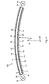
- the Plate combination 4, 16, 18 across its entire width transverse to the longitudinal direction of the Longitudinal ribs 12 continuously curved in the same direction of curvature.
- the curvature can extend over several different radii of curvature. According to the preferred embodiments, however, the curvature extends the plate combination 4, 16, 18 only around a single axis of curvature 38 as Center of curvature.
- the prism plate 4, the cover plate 16 and the light guide plate 18 each consist made of glass or plastic.
- the material is preferably a clear material (in In contrast to a matt material). Colored, translucent ones are also possible Plastics or types of glass for producing colored light.
- FIGS. 3 and 4 contain identical parts like the embodiment of Fig. 1. These parts are therefore the same Reference numbers are provided and will not be described again.
- the light guide plate 102 of FIG. 3 additionally contains a reflector plate 40 which is on the light guide plate 18, on the one facing away from the prism plate 4 Plate surface 22 rests and is adapted to the curvature.
- the plate surface 42 of the reflector plate adjoining the light guide plate 18 40 can be smooth (Fig. 3) or profiled (Fig. 4), matt, glossy or high-gloss. With a profiled design of those adjoining the light guide 18 Plate surface 42 of the reflector plate 40, the profile is preferably by in of the reflector plate 40 formed longitudinal ribs 44 which are parallel to the Longitudinal ribs 12 of the prism plate 4 run, as shown in FIG. 4.
Abstract
Description
Die Erfindung betrifft eine Plattenleuchte gemäß dem Oberbegriff von Anspruch 1.The invention relates to a panel lamp according to the preamble of claim 1.
Eine Plattenleuchte dieser Art ist aus der EP 1 106 905 A2 bekannt.A plate lamp of this type is known from EP 1 106 905 A2.
Durch die Erfindung soll die Aufgabe gelöst werden, eine bessere Rundum-Entblendung zu erzielen.The object of the invention is to achieve a better all-round glare control to achieve.
Eine weitere Aufgabe der Erfindung besteht darin, den Wirkungsgrad zu verbessern.Another object of the invention is to improve efficiency.
Die Plattenleuchte der Erfindung soll konstruktiv einfach und preiswert gestaltet werden.The plate lamp of the invention is designed to be structurally simple and inexpensive become.
Diese Aufgaben werden gemäß der Erfindung durch die kennzeichnenden Merkmale von Anspruch 1 gelöst.These objects are achieved according to the invention by the characteristic features solved by claim 1.
Demgemäß betrifft die Erfindung eine Plattenleuchte, gekennzeichnet durch eine Prismenplatte aus lichtdurchlässigem Material, welche eine glatte Plattenoberfläche und auf der dazu abgewandten Plattenseite eine Prismenoberfläche aufweist, die aus einer Vielzahl von zueinander parallelen, sich in einer Plattenlängsrichtung erstreckenden Längsrippen besteht, welche in der Prismenplatte gebildet sind; eine Deckplatte aus lichtdurchlässigem Material, welche beidseitige eine glatte Plattenoberfläche hat und mit einer dieser glatten Plattenoberflächen auf der Prismenoberfläche der Prismenplatte aufliegt; eine Lichtleiterplatte, welche beidseitig je eine glatte Plattenoberfläche hat und mit einer dieser glatten Plattenoberflächen auf der glatten Plattenoberfläche der Prismenplatte aufliegt, wobei die Lichtleiterplatte mindestens eine Stirnfläche aufweist, die zum Einbringen von Licht von einem Leuchtmittel in die Lichtleiterplatte ausgebildet ist, und wobei die Platten zur Lichtübertragung von der Lichtleiterplatte durch die Prismenplatte und von dieser durch die Deckplatte in einen der Deckplatte benachbarten Raum ausgebildet sind; ferner dadurch gekennzeichnet, dass die Prismenplatte, die Deckplatte und die Lichtleiterplatte über den größten Teil ihrer Plattenbreite aufeinander liegen und quer zur Längsrichtung der Längsrippen der Prismenplatte fortlaufend in gleicher Krümmungsrichtung gekrümmt sind, wobei die Längsrippen auf der Innenseite des Krümmungsbogens der Prismenplatte liegen.Accordingly, the invention relates to a plate lamp, characterized by a Prismatic plate made of translucent material, which has a smooth plate surface and on the plate side facing away from it has a prism surface which from a multitude of parallel to each other, in a plate longitudinal direction extending longitudinal ribs which are formed in the prism plate; a Cover plate made of translucent material, which is smooth on both sides Plate surface and with one of these smooth plate surfaces on the Prism surface of the prism plate rests; a light guide plate, which on both sides each has a smooth plate surface and with one of these smooth plate surfaces rests on the smooth plate surface of the prism plate, the Light guide plate has at least one end face, which is used to introduce light is formed by a lamp in the light guide plate, and wherein the plates for light transmission from the light guide plate through the prism plate and from this are formed by the cover plate in a space adjacent to the cover plate; further characterized in that the prism plate, the cover plate and the Light guide plate lie on top of each other across most of their plate width and across to the longitudinal direction of the longitudinal ribs of the prism plate continuously in the same Are curved direction of curvature, the longitudinal ribs on the inside of the Curvature of the prism plate.
Es hat sich überraschenderweise gezeigt, dass die Erfindung sowohl einen besseren Entblendungswert als auch einen besseren Wirkungsgrad ergibt. Die Plattenleuchte der Erfindung ist konstruktiv einfach und preiswert herzustellen und betriebssicher.Surprisingly, it has been shown that the invention is both a better one Glare control value as well as a better efficiency. The plate light The invention is structurally simple and inexpensive to manufacture and reliable.
Weitere Merkmale der Erfindung sind in den Unteransprüchen enthalten.Further features of the invention are contained in the subclaims.
Die Erfindung wird im folgenden mit Bezug auf die Zeichnungen anhand von
bevorzugten Ausführungsformen als Beispiele beschrieben. In den Zeichnungen
zeigen
Die in Fig. 1 gezeigte Plattenleuchte 2 gemäß der Erfindung enthält eine
Prismenplatte 4 aus lichtdurchlässigem Material, welche eine glatte
Plattenoberfläche 6 und auf der dazu abgewandten Plattenseite eine
Prismenoberfläche 8 aufweist. Die Prismierung ist durch eine Vielzahl von
zueinander parallelen, sich in einer Plattenlängsrichtung 10 (Fig. 2) erstreckende
Längsrippen in der Prismenplatte 4 gebildet. Die Längsrippen 12 bilden zwischen
sich Längsnuten 14. Die Längsrippen 12 und die Längsnuten 14 bilden zusammen
eine in Plattenquerrichtung verlaufende Sägezahnform mit gleichen oder ungleichen
Zahnflanken.The
Eine Deckplatte 16 aus lichtdurchlässigem Material hat beidseitig eine glatte
Plattenoberfläche 15 bzw. 17 und liegt mit einer dieser glatten Oberflächen 17 auf
der Prismenoberfläche 8 der Prismenplatte 4.A
Eine Lichtleiterplatte 18, welche beidseitig je eine glatte Plattenoberfläche 20 bzw.
22 hat und mit einer dieser glatten Plattenoberflächen 20 auf der glatten
Plattenoberfläche 6 der Prismenplatte 4 aufliegt, hat mindestens eine Stirnfläche 24
und/oder 26, die zum Einbringen von Licht von einem Leuchtmittel 28 bzw. 30 in die
Lichtleiterplatte 18 ausgebildet ist. Die mindestens eine Stirnfläche 24 und/oder 26
ist vorzugsweise eine längsverlaufende Stirnfläche, welche parallel zu den
Längsrippen 12 der Prismenoberfläche 8 der Prismenplatte 4 verläuft. Die
Ausführungsform von Fig. 1 enthält auf beiden Längsseiten je eine solche Stirnfläche
24 bzw. 26 und dieser gegenüberliegend je ein Leuchtmittel 28 bzw. 30. Das
Leuchtmittel kann eine Leuchtstofflampe oder eine Glühbirne ein anderes
Leuchtmittel sein.A
Die Platten 4, 16 und 18 sind zur Lichtübertragung von der Lichtleiterplatte 18 durch
die Prismenplatte 4 und von dieser durch die Deckplatte 16 in den an diese
Deckplatte 16 angrenzenden Raum 32 ausgebildet.The
Gemäß der Erfindung ist die Prismenplatte 4, die Deckplatte 16 und die
Lichtleiterplatte 18, welche über ihre gesamte Breite aneinander anliegen, über den
größten Anteil ihrer Breite quer zur Längsrichtung der Längsrippen 12 der
Prismenplatte 4 fortlaufend in gleicher Krümmungsrichtung gekrümmt, wobei die
Längsrippen 12 auf der Innenseite des Krümmungsbogens der Prismenplatte 4
liegen.According to the invention, the
Fig. 2 zeigt durch Doppelpfeile je die Längsrichtung 10 und die Querrichtung 34 der
Plattenleuchte.2 shows the
Die Erfindung ergibt einen besseren Entblendungswert und einen besseren Beleuchtungs-Wirkungsgrad.The invention gives a better glare control and a better Lighting efficiency.
Gemäß den bevorzugten Ausführungsformen der Erfindung ist die
Plattenkombination 4, 16, 18 über ihre gesamte Breite quer zur Längsrichtung der
Längsrippen 12 fortlaufend in gleicher Krümmungsrichtung gekrümmt.According to the preferred embodiments of the invention, the
Die Krümmung kann sich über mehrere verschiedene Krümmungsradien erstrecken.
Gemäß der bevorzugten Ausführungsformen erstreckt sich jedoch die Krümmung
der Plattenkombination 4, 16, 18 nur um eine einzige Krümmungsachse 38 als
Krümmungsmittelpunkt.The curvature can extend over several different radii of curvature.
According to the preferred embodiments, however, the curvature extends
the
Die Prismenplatte 4, die Deckplatte 16 und die Lichtleiterplatte 18 bestehen jeweils
aus Glas oder Kunststoff. Das Material ist vorzugsweise ein klares Material (im
Gegensatz zu einem matten Material). Möglich sind auch gefärbte, lichtdurchlässige
Kunststoffe oder Glasarten zur Erzeugung von farbigem Licht.The
Die Ausführungsformen von Fig. 3 und Fig. 4 enthalten identisch die gleichen Teile
wie die Ausführungsform von Fig. 1. Diese Teile sind deshalb mit den gleichen
Bezugszahlen versehen und werden nicht nochmals beschrieben. Die
Lichtleiterplatte 102 von Fig. 3 enthält zusätzlich eine Reflektorplatte 40, welche auf
der Lichtleiterplatte 18, auf deren von der Prismenplatte 4 abgewandten
Plattenoberfläche 22 aufliegt und an deren Krümmung angepaßt ist.The embodiments of FIGS. 3 and 4 contain identical parts
like the embodiment of Fig. 1. These parts are therefore the same
Reference numbers are provided and will not be described again. The
The
Die an die Lichtleiterplatte 18 angrenzende Plattenoberfläche 42 der Reflektorplatte
40 kann glatt (Fig. 3) oder profiliert (Fig. 4), matt, glänzend oder hochglänzend sein.
Bei einer profilierten Ausbildung der an den Lichtleiter 18 angrenzenden
Plattenoberfläche 42 der Reflektorplatte 40 ist die Profilierung vorzugsweise durch in
der Reflektorplatte 40 gebildete Längsrippen 44 gebildet, welche parallel zu den
Längsrippen 12 der Prismenplatte 4 verlaufen, wie dies Fig. 4 zeigt.The
Claims (7)
dadurch gekennzeichnet, dass die Prismenplatte (4), die Deckplatte (16) und die Lichtleiterplatte (18) über ihre gesamte Plattenbreite quer zur Längsrichtung der Längsrippen (12) der Prismenplatte (4) fortlaufend in gleicher Krümmungsrichtung gekrümmt sind.Panel light according to claim 1,
characterized in that the prism plate (4), the cover plate (16) and the light guide plate (18) are continuously curved over their entire plate width transversely to the longitudinal direction of the longitudinal ribs (12) of the prism plate (4) in the same direction of curvature.
dadurch gekennzeichnet, dass die gesamte Krümmung der Plattenkombination, welche die Prismenplatte (4), die Deckplatte (16) und die Lichtleiterplatte (18) enthält, um eine einzige Krümmungsachse (38) als Krümmungsmittelpunkt sich erstreckt.Panel light according to at least one of the preceding claims,
characterized in that the entire curvature of the plate combination, which includes the prism plate (4), the cover plate (16) and the light guide plate (18), extends around a single axis of curvature (38) as the center of curvature.
dadurch gekennzeichnet, dass auf der Lichtleiterplatte (18), auf ihrer von der Prismenplatte abgewandten Plattenoberseite (22), eine Reflektorplatte (40) aufliegt, die an die Lichtleiterplatte angepaßt gekrümmt ist.Panel light according to at least one of the preceding claims,
characterized in that a reflector plate (40) rests on the light guide plate (18), on its upper side (22) facing away from the prism plate, which is curved to match the light guide plate.
dadurch gekennzeichnet, dass die auf der Lichtleiterplatte (18) aufliegende, Licht reflektierende Plattenoberfläche (42) der Reflektorplatte (40) glatt ist.Panel light according to claim 4,
characterized in that the light-reflecting plate surface (42) of the reflector plate (40) lying on the light guide plate (18) is smooth.
dadurch gekennzeichnet, dass die auf der Lichtleiterplatte (18) aufliegende, Licht reflektierende Plattenoberfläche (42) der Reflektorplatte (40) profiliert ist durch eine Vielzahl von schräg zueinander angeordneten Profilflächen. Panel light according to claim 4,
characterized in that the light-reflecting plate surface (42) of the reflector plate (40) resting on the light guide plate (18) is profiled by a plurality of profile surfaces arranged obliquely to one another.
dadurch gekennzeichnet, dass die Plattenoberfläche (42) der Reflektorplatte (40) eine Vielzahl von in ihr gebildeten, parallel zueinander verlaufende Längsrippen (44) als Profilierung aufweist, deren Rippenseitenflächen sagezahnförmig schräg zueinander angeordnet sind und die Profilflächen bilden, und dass diese Längsrippen (44) parallel zu den Längsrippen (12) der Prismenplatte (4) verlaufen.Panel light according to claim 6,
characterized in that the plate surface (42) of the reflector plate (40) has a plurality of longitudinal ribs (44) formed in it and running parallel to one another, the rib side surfaces of which are obliquely arranged in a sawtooth shape and form the profile surfaces, and that these longitudinal ribs (44 ) run parallel to the longitudinal ribs (12) of the prism plate (4).
Applications Claiming Priority (2)
| Application Number | Priority Date | Filing Date | Title |
|---|---|---|---|
| DE10201556 | 2002-01-17 | ||
| DE10201556A DE10201556A1 (en) | 2002-01-17 | 2002-01-17 | plate lamp |
Publications (1)
| Publication Number | Publication Date |
|---|---|
| EP1329665A1 true EP1329665A1 (en) | 2003-07-23 |
Family
ID=7712338
Family Applications (1)
| Application Number | Title | Priority Date | Filing Date |
|---|---|---|---|
| EP02025867A Ceased EP1329665A1 (en) | 2002-01-17 | 2002-11-19 | Panel illuminator |
Country Status (3)
| Country | Link |
|---|---|
| US (1) | US6749313B2 (en) |
| EP (1) | EP1329665A1 (en) |
| DE (1) | DE10201556A1 (en) |
Families Citing this family (16)
| Publication number | Priority date | Publication date | Assignee | Title |
|---|---|---|---|---|
| KR100523213B1 (en) * | 2001-08-03 | 2005-10-24 | 기길웅 | Advertisement Lighting and for Display and Indirect advertisement lamp |
| DE102006019194A1 (en) * | 2006-04-21 | 2007-10-25 | Semperlux Ag - Lichttechnische Werke - | Multi-sided lighting arrangement with glare control |
| US7751663B2 (en) * | 2006-09-21 | 2010-07-06 | Uni-Pixel Displays, Inc. | Backside reflection optical display |
| US20100139165A1 (en) * | 2007-02-20 | 2010-06-10 | Nobuo Oyama | Light source unit, lighting apparatus using the light source unit, and plant growing equipment using the lighting apparatus |
| GB2453323A (en) * | 2007-10-01 | 2009-04-08 | Sharp Kk | Flexible backlight arrangement and display |
| GB2455057A (en) * | 2007-10-08 | 2009-06-03 | Sharp Kk | Prismatic curved sheet optical device for use in a curved display |
| US20090185389A1 (en) * | 2008-01-18 | 2009-07-23 | Osram Sylvania Inc | Light guide for a lamp |
| US10578789B2 (en) | 2008-03-03 | 2020-03-03 | Abl Ip Holding, Llc | Optical system and method for managing brightness contrasts between high brightness light sources and surrounding surfaces |
| CA2754426C (en) * | 2008-03-03 | 2016-07-26 | Abl Ip Holding, Llc | Optical system and method for managing brightness contrasts between high brightness light sources and surrounding surfaces |
| WO2009130653A1 (en) * | 2008-04-23 | 2009-10-29 | Koninklijke Philips Electronics N.V. | A lighting system |
| EP2390557A1 (en) | 2010-05-31 | 2011-11-30 | Koninklijke Philips Electronics N.V. | Luminaire |
| TWI481910B (en) * | 2013-07-26 | 2015-04-21 | Au Optronics Corp | Back light module |
| DE102014104464A1 (en) * | 2014-03-28 | 2015-10-01 | Trilux Gmbh & Co. Kg | Fully illuminated luminaire |
| US10267972B2 (en) | 2016-10-25 | 2019-04-23 | Svv Technology Innovations, Inc. | Shaped light guide illumination devices |
| CN109479554B (en) * | 2017-09-08 | 2021-10-12 | 松下知识产权经营株式会社 | Plant cultivation device |
| DE102017130025B3 (en) | 2017-12-14 | 2019-03-07 | Klaus Wessling | lighting device |
Citations (7)
| Publication number | Priority date | Publication date | Assignee | Title |
|---|---|---|---|---|
| DE4205137A1 (en) * | 1992-02-20 | 1993-08-26 | Willing Gmbh Dr Ing | Flat hinge-mounted lamp e.g. for wall or ceiling - has diffuser with lamp in one edge and one side coated giving regular and diffuse reflecting areas |
| US5550657A (en) * | 1992-09-14 | 1996-08-27 | Fujitsu Limited | Liquid crystal display device having an optimized ridged layer to improve luminosity |
| EP0940625A2 (en) * | 1998-03-03 | 1999-09-08 | Ford Global Technologies, Inc. | A dimpled manifold optical element for a vehicle lighting system |
| US6044196A (en) * | 1992-03-23 | 2000-03-28 | Minnesota Mining & Manufacturing, Co. | Luminaire device |
| EP1059484A1 (en) * | 1999-05-25 | 2000-12-13 | Siteco Beleuchtungstechnik GmbH | Luminaire with wide beam light intensity distribution |
| EP1106905A2 (en) | 1999-11-30 | 2001-06-13 | GEBRUEDER LUDWIG GmbH | Luminaire |
| US6332690B1 (en) * | 1997-10-22 | 2001-12-25 | Yazaki Corporation | Liquid crystal display with curved liquid crystal screen |
Family Cites Families (7)
| Publication number | Priority date | Publication date | Assignee | Title |
|---|---|---|---|---|
| ATE142763T1 (en) * | 1991-01-16 | 1996-09-15 | Lumitex Inc | THIN PLATE LAMP |
| US5613751A (en) * | 1995-06-27 | 1997-03-25 | Lumitex, Inc. | Light emitting panel assemblies |
| JPH1186620A (en) * | 1997-07-07 | 1999-03-30 | Seiko Epson Corp | Lighting system and notice board |
| EP1055870A1 (en) * | 1999-05-25 | 2000-11-29 | Siteco Beleuchtungstechnik GmbH | Indoor luminaire with refractive glare limiter |
| EP1085252B1 (en) * | 1999-09-17 | 2015-06-10 | Siteco Beleuchtungstechnik GmbH | Light guide luminaire comprising improved shielding means |
| US6356389B1 (en) * | 1999-11-12 | 2002-03-12 | Reflexite Corporation | Subwavelength optical microstructure light collimating films |
| JP2001176315A (en) | 1999-12-15 | 2001-06-29 | Mitsubishi Rayon Co Ltd | Surface type luminescence and desktop lighting system using the same |
-
2002
- 2002-01-17 DE DE10201556A patent/DE10201556A1/en not_active Withdrawn
- 2002-11-19 EP EP02025867A patent/EP1329665A1/en not_active Ceased
-
2003
- 2003-01-16 US US10/347,848 patent/US6749313B2/en not_active Expired - Fee Related
Patent Citations (7)
| Publication number | Priority date | Publication date | Assignee | Title |
|---|---|---|---|---|
| DE4205137A1 (en) * | 1992-02-20 | 1993-08-26 | Willing Gmbh Dr Ing | Flat hinge-mounted lamp e.g. for wall or ceiling - has diffuser with lamp in one edge and one side coated giving regular and diffuse reflecting areas |
| US6044196A (en) * | 1992-03-23 | 2000-03-28 | Minnesota Mining & Manufacturing, Co. | Luminaire device |
| US5550657A (en) * | 1992-09-14 | 1996-08-27 | Fujitsu Limited | Liquid crystal display device having an optimized ridged layer to improve luminosity |
| US6332690B1 (en) * | 1997-10-22 | 2001-12-25 | Yazaki Corporation | Liquid crystal display with curved liquid crystal screen |
| EP0940625A2 (en) * | 1998-03-03 | 1999-09-08 | Ford Global Technologies, Inc. | A dimpled manifold optical element for a vehicle lighting system |
| EP1059484A1 (en) * | 1999-05-25 | 2000-12-13 | Siteco Beleuchtungstechnik GmbH | Luminaire with wide beam light intensity distribution |
| EP1106905A2 (en) | 1999-11-30 | 2001-06-13 | GEBRUEDER LUDWIG GmbH | Luminaire |
Also Published As
| Publication number | Publication date |
|---|---|
| US6749313B2 (en) | 2004-06-15 |
| US20030133285A1 (en) | 2003-07-17 |
| DE10201556A1 (en) | 2003-07-31 |
Similar Documents
| Publication | Publication Date | Title |
|---|---|---|
| EP1329665A1 (en) | Panel illuminator | |
| EP0780265A2 (en) | Vehicle rear light | |
| DE19803518A1 (en) | Rod-shaped light guide | |
| EP0533301B1 (en) | Advisory sign, illuminated from rear | |
| EP1073862A1 (en) | Light guiding device for an oblong light source | |
| EP0933588A2 (en) | Vehicle light | |
| DE10251849A1 (en) | Optical conductor for vehicles, preferably motor vehicles, has reflection surfaces offset relative to each other and, looking in radiation direction, bounding on each other essentially with no gaps | |
| EP0138747A1 (en) | Parabolic strip element for elongated lamps | |
| DE4109492C2 (en) | Luminaire louvre for louvre luminaires equipped with discharge lamps | |
| DE19961491A1 (en) | Light, especially interior light, has hollow light conductor formed by housing with reflective walls bounded at least partly by output coupling device with opposing reflective cover surface | |
| DE69833421T2 (en) | Light emission optics for vehicle signal lights | |
| DE202007014598U1 (en) | license plate light | |
| EP0721086B1 (en) | Flat lighting device | |
| EP1106905B1 (en) | Luminaire | |
| DE3517610A1 (en) | MULTIPLE DISC INSULATING GLASS UNIT WITH INTEGRATED LIGHT-GUIDING SYSTEM | |
| DE2748947A1 (en) | Car internal light - has integral louvres formed by slotting lens and filling with blackening material | |
| DE10011378B4 (en) | Hollow-light luminaire with indirect light emission | |
| EP1496308B1 (en) | Interior Light with a refractive element | |
| DE4215968A1 (en) | Light guiding structure for illuminating at least part of room with daylight - utilises daylight entering room through window assisted by elements located on wall or ceiling to reflect the light | |
| EP0911577A2 (en) | Electric lamp | |
| EP0903535A2 (en) | Louvre system for lamps | |
| EP1209409B1 (en) | Outdoor lamp having an improved illumination output | |
| DE10354462B4 (en) | Luminaire with asymmetrical light emission | |
| EP1065436B1 (en) | Ceiling light with lightguide | |
| EP3663635B1 (en) | Anti-glare lens stabilizer |
Legal Events
| Date | Code | Title | Description |
|---|---|---|---|
| PUAI | Public reference made under article 153(3) epc to a published international application that has entered the european phase |
Free format text: ORIGINAL CODE: 0009012 |
|
| AK | Designated contracting states |
Designated state(s): AT BE BG CH CY CZ DE DK EE ES FI FR GB GR IE IT LI LU MC NL PT SE SK TR |
|
| AX | Request for extension of the european patent |
Extension state: AL LT LV MK RO SI |
|
| 17P | Request for examination filed |
Effective date: 20031202 |
|
| AKX | Designation fees paid |
Designated state(s): AT CH DE LI |
|
| 17Q | First examination report despatched |
Effective date: 20060905 |
|
| APBN | Date of receipt of notice of appeal recorded |
Free format text: ORIGINAL CODE: EPIDOSNNOA2E |
|
| APBR | Date of receipt of statement of grounds of appeal recorded |
Free format text: ORIGINAL CODE: EPIDOSNNOA3E |
|
| APAF | Appeal reference modified |
Free format text: ORIGINAL CODE: EPIDOSCREFNE |
|
| APBT | Appeal procedure closed |
Free format text: ORIGINAL CODE: EPIDOSNNOA9E |
|
| STAA | Information on the status of an ep patent application or granted ep patent |
Free format text: STATUS: THE APPLICATION HAS BEEN REFUSED |
|
| 18R | Application refused |
Effective date: 20100512 |