The present invention relates to electronic
apparatus capable of being loaded with, for example,
an SD (secure digital) card, and more specifically, to
a structure for preventing the SD card from slipping
off.
SD cards that can store masses of image, voice,
and other data are widely used in electronic
apparatuses such as portable computers and PDAs
(personal digital assistants).
An electronic apparatus that can be loaded with an
SD card is furnished with a card receptacle. The card
receptacle comprises a card slot into which the SD card
can be inserted, a card connector that faces the card
slot, and a locking mechanism for holding the SD card
in the card receptacle.
The locking mechanism has a metallic lock lever.
The lock lever is located between the card slot and
the card connector. The lock lever has an elastically
deformable tongue portion on its distal end, the
tongue portion projecting into the card receptacle.
When the SD card is inserted into the card receptacle
through the card slot, the tongue portion is
elastically fitted into a notch that is formed in a
side edge of the card. Thus, the SD card can be held
in the card receptacle without the possibility of its
slipping off.
If the SD card is drawn out of the card slot, the
tongue portion of the lock lever is elastically
deformed, yielding to the pull, and is disengaged from
the notch. Thereupon, the SD card is released from the
locking lever and unlocked, so that it can be taken out
of the card receptacle.
According to the locking mechanism, the tongue
portion of the lock lever rubs against the side edge of
the SD card every time the card is inserted into or
drawn out of the card receptacle. At the same time,
the tongue portion is fitted into the notch of the card
or elastically deformed in a direction such that it
slips out of the notch.
If the insertion and removal of the SD card are
repeated, therefore, the tongue portion of the lock
lever inevitably wears or is lowered in springiness.
In consequence, the engagement between the tongue
portion of the lock lever and the notch of the SD card
may possibly be deficient. Thus, the SD card easily
slips off the card receptacle if any vibration or shock
acts on the electronic apparatus, for example.
The embodiment of the present invention provides
an electronic apparatus capable of securely holding a
card in a holder and preventing the card from slipping
off unexpectedly.
In order to achieve the above embodiment, an
electronic apparatus according to the invention
comprises a body and a holder for holding a card. The
holder is supported on the body, and is movable between
a first position in which the holder is held in the
body and a second position in which the holder is
disengaged from the body. The body has an engaging
portion. The engaging portion is removably caught by
the card in the holder when the holder is moved to the
first position.
In incorporating the card into the body with this
configuration, the holder is moved to the second
position. After the holder is then loaded with the
card, it is moved from the second position to the first
position. As this is done, the engaging portion is
caught by the card, and the card is locked by means of
the holder.
In taking out the card from the body, the holder
is moved from the first position to the second
position. As this is done, the card, along with the
holder, recedes from the body and is disengaged from
the engaging portion of the body. Thus, the card is
unlocked.
When the card is incorporated into or removed from
the body, according to this configuration, no
components rub against it or undergo elastic
deformation. Thus, the card can be prevented from
being deficiently locked owing to abrasion of the
components or lowering of their springiness.
This summary of the invention does not necessarily
describe all necessary features so that the invention
may also be a sub-combination of these described
features.
The invention can be more fully understood from
the following detailed description when taken in
conjunction with the accompanying drawings, in which:
A first embodiment of the present invention will
now be described with reference to FIGS. 1 to 9.
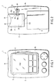
FIGS. 1 to 4 show a PDA (personal digital
assistant) 1 as an electronic apparatus. The PDA 1 has
a plastic apparatus body 2. The body 2 is in the form
of a flat box that has a bottom wall 2a, front wall 2b,
left- and right- hand sidewalls 2c and 2d, upper end
wall 2e, and lower end wall 2f.
The apparatus body 2 contains a printed wiring
board 3 therein. The printed wiring board 3 is located
parallel to the bottom and front walls 2a and 2b of the
body 2. A liquid crystal display unit 4 and a tablet 5
are held between the printed wiring board 3 and the
front wall 2b. The display unit 4 and the tablet 5
overlap each other. The tablet 5 has a screen 5a, as
shown in FIG. 1. The screen 5a is exposed to the
outside of the body 2 through an opening 6 in the front
wall 2b.
The apparatus body 2 is provided with a battery
storage portion 8 and a holder supporting portion 9.
The battery storage portion 8 is used to store
batteries 10 for use as power sources for the PDA 1.
The storage portion 8 is formed of a recess that opens
in the bottom wall 2a and the lower end wall 2f of the
body 2 and is closed by means of a removable battery
cover 11.
The holder supporting portion 9 is situated behind
the liquid crystal display unit 4 and in the upper half
of the apparatus body 2. The supporting portion 9 is
formed of a recess in the body 2, which opens in the
bottom wall 2a and the upper end wall 2e of the body 2.
The holder supporting portion 9 has a bottom wall 13a,
left- and right- hand sidewalls 13b and 13c, and an end
wall 13d. The bottom wall 13a is located parallel to
the printed wiring board 3. The sidewalls 13b and 13c
and the end wall 13d rise individually from the edge
portions of the bottom wall 13a toward the bottom wall
2a of the body 2.
As shown in FIGS. 3 and 4, a card connector 15 is
mounted on the printed wiring board 3. The card
connector 15 has connecting terminals 16. The
terminals 16 are arranged in a line in the width
direction of the apparatus body 2 and exposed to
the holder supporting portion 9 through the bottom
wall 13a.
The holder supporting portion 9 has a pair of
engaging projections 17. The projections 17 are
situated individually in two corner portions that are
defined by the bottom wall 13a and the sidewalls 13b
and 13c. The projections 17 protrude from the walls
13a, 13b and 13c at right angles thereto toward the
inner part of the supporting portion 9.
As shown in FIGS. 2 to 5, the holder supporting
portion 9 of the apparatus body 2 supports a plastic
cardholder 20. The cardholder 20 is used to hold an SD
(secure digital) card 21 in a removable manner. As
shown in FIG. 9, the SD card 21 has contacts 22 and a
pair of notches 23. The contacts 22 are situated on
one end portion of the SD card 21 and arranged in a
line in the width direction of the card 21. The
notches 23 are situated individually in the respective
middle portions of the left- and right-hand side edges
of the SD card 21. The notches 23 are just large
enough to receive their corresponding projections 17.
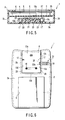
The cardholder 20 that holds the SD card 21 is in
the form of a flat box that can be fitted tight in the
holder supporting portion 9. The cardholder 20 has a
card slot 25 for the insertion and removal of the SD
card 21 and an opening 26 through which the contacts 22
of the card 21 can be exposed. The card slot 25 is
situated at one end of the cardholder 20. The opening
26 is situated at the other end of the cardholder 20
opposite from the card slot 25, and faces the
connecting terminals 16 of the card connector 15 that
are exposed to the holder supporting portion 9.
Further, the cardholder 20 has a pair of through
holes 27, as shown in FIGS. 7 and 8. The through holes
27 are situated individually in the left- and right-hand
portions of the cardholder 20. Each through hole
27 is in the form of a slit that is just large enough
for the passage of each corresponding engaging
projection 17. The through holes 27 can be aligned
individually with the notches 23 of the SD card 21 when
the card 21 is inserted in the card slot 25.
The cardholder 20 has a pair of shafts 28 on its
other end. The shafts 28 are fitted individually in
sockets 29 that are bored individually in the sidewalls
13b and 13c of the holder supporting portion 9. Thus,
the cardholder 20 is supported on the apparatus body 2
by means of the shafts 28 so as to be rockable between
first and second positions.
FIGS. 2 and 3 show the cardholder 20 in the first
position. In this first position, the cardholder 20 is
held in the holder supporting portion 9. Accordingly,
the cardholder 20 overlaps the bottom wall 13a, and its
opening 26 faces the connecting terminals 16 of the
card connector 15. As long as the cardholder 20 is in
the first position, moreover, the engaging projections
17 of the holder supporting portion 9 are located in
their corresponding through holes 27 and inside the
cardholder 20.
FIG. 4 shows the cardholder 20 in the second
position. In this second position, the cardholder 20
is tilted away from the bottom wall 13a of the holder
supporting portion 9 and juts out from the bottom wall
2a of the apparatus body 2. Accordingly, the card slot
25 of the cardholder 20 outwardly projects long from
the holder supporting portion 9, and the engaging
projections 17 of the supporting portion 9 are
disengaged from the through holes 27 of the
cardholder 20.
As seen from FIGS. 2 and 6, the apparatus body 2
is provided with a locking mechanism 31 for locking the
cardholder 20 in the first position. The locking
mechanism 31 includes a locking tongue 32 that is
supported on the bottom wall 2a of the body 2. The
tongue 32 has a distal end 32a that adjoins the holder
supporting portion 9. The locking tongue 32 can slide
between a locking position and an unlocking position.
When the locking tongue 32 is slid to the locking
position, its distal end 32a advances into the holder
supporting portion 9 through the sidewall 13c. When
the tongue 32 is slid to the unlocking position, the
distal end 32a withdraws from the holder supporting
portion 9 into the body 2.
If the locking tongue 32 is slid to the locking
position when the cardholder 20 is in the first
position, its distal end 32a is caught by an engaging
hole 33 in the right-hand side portion of the
cardholder 20. Thus, the cardholder 20 is restricted
from rocking freely and is locked in the first
position.
If the locking tongue 32 is slid from the locking
position to the unlocking position when the cardholder
20 is in the first position, its distal end 32a is
disengaged from the engaging hole 33. Thus, the
cardholder 20 is unlocked or released from the locking
tongue 32, so that it can be rocked from the first
position to the second position.
The locking tongue 32 has an operating part 34.
The operating part 34 is exposed to the outside of the
bottom wall 2a of the apparatus body 2 so that it is
accessible to an operator's fingertip. Thus, the
operator can manually slide the locking tongue 32 to
the locking or unlocking position.
The following is a description of steps of
procedure for incorporating the SD card 21 into the PDA
1 arranged in this manner.
First, the locking tongue 32 is slid from the
locking position to the unlocking position, whereupon
the cardholder 20 is unlocked or released from the
locking tongue 32. Then, the cardholder 20 is rocked
from the first position to the second position,
whereupon it is lifted from the holder supporting
portion 9. In this state, the SD card 21 is put into
the card slot 25 of the cardholder 20. The card 21 is
inserted into the cardholder 20 with its one end,
having the contacts 22, at the head.
When the SD card 21 is fully inserted into the
cardholder 20, the contacts 22 are exposed to the
outside of the cardholder 20 through the opening 26.
At the same time, the notches 23 of the card 21 are
aligned individually with the through holes 27 of the
cardholder 20.
Then, the cardholder 20 is rocked from the second
position to the first position. As this is done, the
contacts 22 of the SD card 21 run against the
connecting terminals 16 of the card connector 15 so
that it is connected electrically to the printed wiring
board 3. Subsequently, the cardholder 20 approaches
the bottom wall 13a of the holder supporting portion 9,
and the engaging projections 17 that protrude from the
bottom wall 13a get into the notches 23 of the SD card
21 through the through holes 27, individually.
Thereupon, the respective positions of the SD card 21
and the cardholder 20 are fixedly settled, and the card
21 is locked lest it slip out of the cardholder 20.
Finally, the locking tongue 32 is slid from the
unlocking position to the locking position. As this is
done, the distal end 32a of the locking tongue 32 is
caught by the engaging hole 33 of the cardholder 20,
whereupon the cardholder 20 is locked in the first
position.
In taking out the SD card 21 from the PDA 1, the
locking tongue 32 is slid from the locking position to
the unlocking position to unlock the cardholder 20.
Then, the cardholder 20 is rocked from the first
position to the second position. As this is done, the
cardholder 20 recedes from the bottom wall 13a of the
holder supporting portion 9, and the engaging
projections 17 of the supporting portion 9 get out
of the notches 23 of the SD card 21 and the through
holes 27 of the cardholder 20, individually. Thus, the
SD card 21 is unlocked and disengaged from the
cardholder 20.
At the same time, the contacts 22 of the SD card
21 leave the connecting terminals 16 of the card
connector 15, whereupon the card 21 is released from
the electrical connection with the printed wiring board
3. When the cardholder 20 reaches the second position,
the card slot 25 outwardly projects long from the
apparatus body 2, whereupon the SD card 21 is allowed
to be drawn out of the card slot 25.
As the cardholder 20 having the SD card 21 therein
is rocked, according to the PDA 1 constructed in this
manner, the engaging projections 17 of the apparatus
body 2 get individually into the notches 23 of the card
21, thereby locking the card 21 in the cardholder 20,
or slip out of the notches 23, thereby unlocking the
card 21.
When the SD card 21 is locked or unlocked,
therefore, no components rub against it or undergo
elastic deformation. Thus, the card 21 can be
prevented from being deficiently locked owing to
abrasion of the components or lowering of their
springiness. In consequence, the card 21 never
unexpectedly slips off the PDA 1 if the PDA 1 is
subjected to any vibration or shock. Thus, the SD card
21 can be prevented from being rendered missing or
damaged.
The present invention is not limited to the first
embodiment described above. FIGS. 10 and 11 show a
second embodiment of the invention.
According to this second embodiment, the engaging
projections 17 and the locking mechanism 31 are
combined together to prevent the SD card 21 from
slipping off. The second embodiment shares other basic
configurations of the PDA 1 with the first embodiment.
Therefore, like reference numerals are used to
designate like components of the first and second
embodiments, and a description of those components will
not be repeated.
As shown in FIGS. 10 and 11, the locking tongue 32
of the locking mechanism 31 has an extended portion 41
on its distal end 32a. The extended portion 41 is
adapted to penetrate the engaging hole 33 of the
cardholder 20 in the first position when the locking
tongue 32 is slid to the locking position. The
extended portion 41 is located side by side with the
right-hand engaging projection 17 as it advances into
the cardholder 20.
The right-hand notch 23 of the SD card 21 has a
receiving portion 42 that is spread so that the
extended portion 41 of the locking tongue 32 can get
into it. The receiving portion 42 faces the engaging
hole 33 of the cardholder 20 when the SD card 21 is
inserted into the cardholder 20 through the card
slot 25.
If the locking tongue 32 is slid to the locking
position after the cardholder 20, having the SD card 21
therein, is rocked to the first position, according to
the configuration described above, the extended portion
41 of the locking tongue 32 gets into the receiving
portion 42 of the card 21. Thus, the locking tongue 32
serves both as means for preventing the cardholder 20
from opening and as means for preventing the card 21
from slipping off. In consequence, the SD card 21 can
be prevented more securely from slipping off.
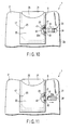
FIGS. 12 and 13 show a third embodiment of the
invention.
The third embodiment differs from the second
embodiment in that the SD card 21 is prevented from
slipping off by means of the locking mechanism 31. The
third embodiment shares other basic configurations of
the PDA 1 with the second embodiment.
As shown in FIGS. 12 and 13, the SD card 21 has a
notch 51 in its right-hand edge. The notch 51 is
adapted to face the engaging hole 33 of the cardholder
20 when the card 21 is fully inserted into the
cardholder 20.
If the locking tongue 32 is slid to the locking
position with the cardholder 20, having the SD card 21
therein, situated in the first position, therefore, the
extended portion 41 of the locking tongue 32 gets into
the notch 51 of the card 21 through the engaging hole
33 of the cardholder 20. Accordingly, the locking
tongue 32 locks the cardholder 20 in the first
position, and at the same time, the SD card 21 is
locked lest it slip out of the cardholder 20.
According to this configuration, the holder
supporting portion 9 need not be provided with the
engaging projections that are caught by the SD card 21,
and the through holes that receive the engaging
projections need not be formed in the cardholder 20.
Thus, the apparatus body 2 and the cardholder 20 can be
simplified in construction, and costs can be lowered.
The card used in the present invention is not
limited to the SD card. For example, it may be a
memory card, such as a solid-state floppy disc card
(SSFDC), or some other IC card.
Further, the electronic apparatus according to the
present invention is not limited to the PDA, and may be
any other apparatus such as a portable computer or
portable telephone.