EP1324095A2 - Transmitted light lighting device for microscope - Google Patents
Transmitted light lighting device for microscope Download PDFInfo
- Publication number
- EP1324095A2 EP1324095A2 EP03004724A EP03004724A EP1324095A2 EP 1324095 A2 EP1324095 A2 EP 1324095A2 EP 03004724 A EP03004724 A EP 03004724A EP 03004724 A EP03004724 A EP 03004724A EP 1324095 A2 EP1324095 A2 EP 1324095A2
- Authority
- EP
- European Patent Office
- Prior art keywords
- light
- light sources
- illumination
- led
- lighting
- Prior art date
- Legal status (The legal status is an assumption and is not a legal conclusion. Google has not performed a legal analysis and makes no representation as to the accuracy of the status listed.)
- Granted
Links
Images
Classifications
-
- G—PHYSICS
- G02—OPTICS
- G02B—OPTICAL ELEMENTS, SYSTEMS OR APPARATUS
- G02B21/00—Microscopes
- G02B21/06—Means for illuminating specimens
-
- G—PHYSICS
- G02—OPTICS
- G02B—OPTICAL ELEMENTS, SYSTEMS OR APPARATUS
- G02B21/00—Microscopes
- G02B21/06—Means for illuminating specimens
- G02B21/08—Condensers
- G02B21/086—Condensers for transillumination only
Definitions
- Illumination arrangements on microscopes have a relatively poor efficiency in converting the electrical power consumed into usable light output and they generate disruptive heat.
- installation space is required for upright tripods that prevent ergonomically favorable arrangements of the microscope stage.
- the solutions are complex and therefore expensive.
- Illumination devices for microscopes with LEDs or LCDs are known from DE 3108389A1, US 4852985, DE 3734691 C2, DE 19644662A1.
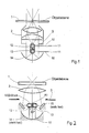
- a lighting unit consisting of condenser optics 2 and aperture diaphragm 3 is arranged under a transparent microscope stage 1, on which there is a sample that is viewed through a lens, not shown, the other parts of the microscope stand are not shown here.
- a suitably chosen number of white light LEDs (preferably 2) is placed near the aperture diaphragm plane, as shown in Figure 1.
- one LED 12 shines upwards and the second LED 13 downwards.
- the lower LED is arranged in the focal point of a concave mirror 14. Slight shading problems can be kept small by minimizing the dimensions of the LED block.
- the LEDs are supplied with electricity via lines 10 from a power supply 11.
- the upward-shining LED 12 has the task of primary field illumination via the condenser 2, while the light of the second downward-shining light, which is preferably arranged in the focal point of a parabolic mirror 14, is reflected back in parallel and provides the necessary aperture illumination via the condenser 2.
- the block of both LEDs 12 and 13 can also be rotated 90 ° around an axis of rotation A 1 perpendicular to the plane of the drawing, as in FIG. right.
- An oblique illumination is generated via two deflecting mirrors 15 or a deflecting mirror ring, the LEDs being able to be arranged in their central axis in addition to the rotation mentioned above.
- the arrangement of the LEDs can also be used to implement the spatial image method with clocked lighting, as proposed by the applicant in EP 730 181, the entire contents of which are hereby incorporated by reference.
- the beam flow of the LED's which are timed via their power supply with an observation shutter, is reflected with the angles in the direction of the condenser that are necessary for the creation of a room by the lighting.
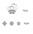
- FIG. 3 shows how several white light LEDs are as close as possible a plane conjugated to the pupil, which can also be a spherical surface are arranged and so without scatter material for the required light conductance to care.
- the LEDs are arranged so that the tangents of their Touch radiation cone (Fig. 3a) by the angle between the center axes their radiation cone essentially with the angle of the radiation cone matches.
- a larger radiant area can be offered with the same divergence angle as that of a single LED. Due to the directed tilting u. ostrich-shaped grouping of the individual LEDs in such a way that the tangents of the radiation cones touch, both a larger area and a larger summary radiation angle are generated.
- Arrangements according to FIG. 3 can advantageously be used in the arrangements according to FIGS. 1 and 2.
- the field and aperture illumination can also be provided by an array Microlenses with different focal lengths are made.
- LED lighting unit advantages are long Lifespan, minimal energy consumption, daylight-like color temperature, color temperature-independent brightness control and low Heat.
Abstract
Description
Beleuchtungsanordnungen an Mikroskopen haben einen relativ schlechten
Wirkungsgrad bei der Umsetzung von aufgenommener elektrischer Leistung in
nutzbare Lichtleistung und sie erzeugen störende Wärme.
Darüber hinaus werden bei aufrechten Stativen Bauräume benötigt, die
ergonomisch günstige Anordnungen des Mikroskoptisches verhindern.
Schliesslich sind die Lösungen bauteilaufwendig und damit teuer.
Beleuchtungseinrichtungen für Mikroskope mit LED's bzw. LCD's sind aus
DE 3108389A1, US 4852985, DE 3734691 C2, DE 19644662A1 bekannt.Illumination arrangements on microscopes have a relatively poor efficiency in converting the electrical power consumed into usable light output and they generate disruptive heat.
In addition, installation space is required for upright tripods that prevent ergonomically favorable arrangements of the microscope stage. After all, the solutions are complex and therefore expensive. Illumination devices for microscopes with LEDs or LCDs are known from DE 3108389A1, US 4852985, DE 3734691 C2, DE 19644662A1.
Die genannten Nachteile sollen durch eine LED-Beleuchtungseinheit - bestehend aus einer oder mehreren angeordneten LED's - beseitigt werden, die wahlweise netzabhängig oder durch Batterien betrieben werden.The disadvantages mentioned are said to be due to an LED lighting unit - consisting of one or more arranged LEDs - can be eliminated can be operated either depending on the network or on batteries.
Diese Aufgabe wird durch die Merkmale der unabhängigen Ansprüche gelöst. Bevorzugte Weiterbildungen sind Gegenstand der abhängigen Ansprüche.This object is solved by the features of the independent claims. Preferred developments are the subject of the dependent claims.
Die Erfindung und ihre Wirkungen und Vorteile werden nachstehend anhand der
schematischen Zeichnungen erläutert.
In Fig. 1 ist unter einem durchsichtigen Mikroskoptisch 1, auf dem sich eine
Probe befindet, die durch ein nicht dargestelltes Objektiv betrachtet wird, eine
Beleuchtungseinheit, bestehend aus Kondensoroptik 2 und Aperturblende 3,
angeordnet, die weiteren Teile des Mikroskopstatives sind hier nicht dargestellt.The invention and its effects and advantages are explained below with reference to the schematic drawings.
In Fig. 1, a lighting unit consisting of
Eine geeignet gewählte Anzahl von Weisslicht-LED's (vorzugsweise 2) wird,
wie im Bild 1 dargestellt, in der Nähe der Apereturblendenebene angeordnet.
In einer ersten Ausführungsform strahlt eine LED 12 nach oben und die zweite
LED 13 nach unten. Die untere LED ist im Brennpunkt eines Hohlspiegels 14
angeordnet. Leichte Abschattungsprobleme können durch möglichst geringe
Abmessungen des LED- Blocks klein gehalten werden.
Die LEDs werden über Leitungen 10 von einer Stromversorgung 11 elektrisch
versorgt.
Die nach oben strahlende LED 12 hat die Aufgabe der vorrangigen
Feldausleuchtung über den Kondensor 2, während das Licht der zweiten nach
unten strahlenden, die im Brennpunkt vorzugsweise eines Parabolspiegels 14
angeordnet ist, parallel zurückgestrahlt wird und für die notwendige
Aperturausleuchtung über den Kondensor 2 sorgt.
Der Block beider LED's 12 und 13 kann auch wie in Fig.2 um 90° um eine
Drehachse A 1 senkrecht zur Zeichenebene gedreht werden, strahlt also nach
links u. rechts.
Über zwei Umlenkspiegel 15 oder einen Umlenkspiegelring, wobei die LEDs
zusätzlich zur oben erwähnten Drehung in ihrer Mittenachse um die optische
Achse drehbar angeordnet sein können, wird eine Schrägbeleuchtung erzeugt.A suitably chosen number of white light LEDs (preferably 2) is placed near the aperture diaphragm plane, as shown in Figure 1. In a first embodiment, one
The LEDs are supplied with electricity via
The upward-
The block of both
An oblique illumination is generated via two
Die Anordnung der LEDs kann auch zur Realisierung des Raumbildverfahrens
mit getakteter Beleuchtung verwendet werden, wie es von der Anmelderin in EP
730 181, auf deren kompletten Inhalt hiermit Bezug genommen wird,
vorgeschlagen wurde.
Dazu wird der Strahlenfluss der zeitlich über ihre Stromversorgung mit einem
Beobachtungsshutter getakteten LED's mit den für eine Raumbilderzeugung
durch die Beleuchtung notwendigen Winkeln in Richtung des Kondensors
reflektiert.The arrangement of the LEDs can also be used to implement the spatial image method with clocked lighting, as proposed by the applicant in EP 730 181, the entire contents of which are hereby incorporated by reference.
For this purpose, the beam flow of the LED's, which are timed via their power supply with an observation shutter, is reflected with the angles in the direction of the condenser that are necessary for the creation of a room by the lighting.
In Fig. 3 ist dargestellt , wie mehrere Weisslicht-LED's so nahe wie möglich in einer der Pupille konjugierten Ebene, die auch eine Kugelfläche sein kann, angeordnet sind und so auch ohne Streumittel für den benötigten Lichtleitwert sorgen.FIG. 3 shows how several white light LEDs are as close as possible a plane conjugated to the pupil, which can also be a spherical surface are arranged and so without scatter material for the required light conductance to care.
Hierzu sind die LED's so angeordnet, dass sich die Tangenten ihrer Abstrahlkegel berühren (Fig. 3a), indem der Winkel zwischen den Mittenachsen ihrer Abstrahlkegel im Wesentlichen mit dem Winkel des Abstrahlkegels übereinstimmt. For this purpose, the LEDs are arranged so that the tangents of their Touch radiation cone (Fig. 3a) by the angle between the center axes their radiation cone essentially with the angle of the radiation cone matches.
Über das flächenhafte Parallelschalten einzelner LED's in verschiedenen
Anordnungen wie in Fig. 3b dargestellt, kann eine größere strahlende Fläche mit
dem gleichen Divergenzwinkel wie der einer einzelnen LED angeboten werden.
Durch das gerichtete Verkippen u. straussförmige Zusammenfassen der
einzelnen LED's in der Weise, dass sich die Tangenten der Abstrahlkegel
berühren, werden sowohl eine größere Fläche als auch ein größerer
summarischer Abstrahlwinkel erzeugt.
Anordnungen gemäss Fig.3 sind vorteilhaft in den Anordnungen nach Fig.1 und
2 anwendbar.Through the areal parallel connection of individual LEDs in different arrangements as shown in Fig. 3b, a larger radiant area can be offered with the same divergence angle as that of a single LED. Due to the directed tilting u. ostrich-shaped grouping of the individual LEDs in such a way that the tangents of the radiation cones touch, both a larger area and a larger summary radiation angle are generated.
Arrangements according to FIG. 3 can advantageously be used in the arrangements according to FIGS. 1 and 2.
Des Weiteren kann die Feld- und Aperturausleuchtung auch durch ein Array aus Mikrolinsen mit unterschiedlichen Brennweiten erfolgen.Furthermore, the field and aperture illumination can also be provided by an array Microlenses with different focal lengths are made.
Weitere Vorteile des Einsatzes der LED-Beleuchtungseinheit sind lange Lebensdauer, minimaler Energiebedarf, tageslichtähnliche Farbtemperatur, farbtemperatur-unabhängige Helligkeitsregelung und geringe Wärmeentwicklung.Other advantages of using the LED lighting unit are long Lifespan, minimal energy consumption, daylight-like color temperature, color temperature-independent brightness control and low Heat.
Claims (7)
Applications Claiming Priority (3)
| Application Number | Priority Date | Filing Date | Title |
|---|---|---|---|
| DE19919096 | 1999-04-27 | ||
| DE19919096A DE19919096A1 (en) | 1999-04-27 | 1999-04-27 | Transmitted light illumination device for microscopes |
| EP00938611A EP1180249B1 (en) | 1999-04-27 | 2000-04-22 | Transmitted light/lighting device for microscopes |
Related Parent Applications (1)
| Application Number | Title | Priority Date | Filing Date |
|---|---|---|---|
| EP00938611A Division EP1180249B1 (en) | 1999-04-27 | 2000-04-22 | Transmitted light/lighting device for microscopes |
Publications (3)
| Publication Number | Publication Date |
|---|---|
| EP1324095A2 true EP1324095A2 (en) | 2003-07-02 |
| EP1324095A3 EP1324095A3 (en) | 2003-07-09 |
| EP1324095B1 EP1324095B1 (en) | 2004-07-21 |
Family
ID=7906019
Family Applications (3)
| Application Number | Title | Priority Date | Filing Date |
|---|---|---|---|
| EP03004724A Expired - Lifetime EP1324095B1 (en) | 1999-04-27 | 2000-04-22 | Transmitted light lighting device for microscope |
| EP03004725A Expired - Lifetime EP1316833B1 (en) | 1999-04-27 | 2000-04-22 | Transmitted light/lighting device for microscopes |
| EP00938611A Expired - Lifetime EP1180249B1 (en) | 1999-04-27 | 2000-04-22 | Transmitted light/lighting device for microscopes |
Family Applications After (2)
| Application Number | Title | Priority Date | Filing Date |
|---|---|---|---|
| EP03004725A Expired - Lifetime EP1316833B1 (en) | 1999-04-27 | 2000-04-22 | Transmitted light/lighting device for microscopes |
| EP00938611A Expired - Lifetime EP1180249B1 (en) | 1999-04-27 | 2000-04-22 | Transmitted light/lighting device for microscopes |
Country Status (6)
| Country | Link |
|---|---|
| US (2) | US6674575B1 (en) |
| EP (3) | EP1324095B1 (en) |
| JP (1) | JP2002543453A (en) |
| AT (3) | ATE239926T1 (en) |
| DE (4) | DE19919096A1 (en) |
| WO (1) | WO2000065398A2 (en) |
Cited By (2)
| Publication number | Priority date | Publication date | Assignee | Title |
|---|---|---|---|---|
| DE102004029057A1 (en) * | 2004-06-16 | 2006-01-12 | Carl Zeiss | Lighting device and optical observation device |
| WO2011020550A1 (en) * | 2009-08-18 | 2011-02-24 | Carl Zeiss Microimaging Gmbh | Lighting device for microscopes and macroscopes |
Families Citing this family (35)
| Publication number | Priority date | Publication date | Assignee | Title |
|---|---|---|---|---|
| DE10228985A1 (en) * | 2002-06-28 | 2004-01-15 | Leica Mikrosysteme Gmbh | Illumination device for microtomes or ultramicrotomes |
| DE10246275A1 (en) * | 2002-10-02 | 2004-04-15 | Leica Microsystems Wetzlar Gmbh | Portable microscope with lighting device and microscope stage |
| DE10246889B4 (en) † | 2002-10-08 | 2004-08-19 | Karl Kaps Gmbh & Co. Kg | Lighting device for an optical magnification device and optical magnification device |
| DE10314125B4 (en) | 2003-03-28 | 2005-02-24 | Carl Zeiss Jena Gmbh | Arrangement for illuminating objects with light of different wavelengths |
| DE10339619A1 (en) * | 2003-08-28 | 2005-03-24 | Leica Microsystems (Schweiz) Ag | Stereomicroscope with integrated epi-illumination device |
| US20050219689A1 (en) * | 2004-03-31 | 2005-10-06 | Copeland David J | Microscope with retractable cord |
| US7315414B2 (en) * | 2004-03-31 | 2008-01-01 | Swift Instruments, Inc. | Microscope with adjustable stage |
| US20050259437A1 (en) * | 2004-05-19 | 2005-11-24 | Klein Gerald L | Apparatus, systems and methods relating to illumination for microscopes |
| ITMI20050019A1 (en) * | 2005-01-07 | 2006-07-08 | Fraen Corp Srl | FLUORESCENCE MICROSCOPE IN TRANSMITTED LIGHT AND MICROSCOPE ADAPTATION KIT FOR FLUORESCENT WORKING MODE IN TRANSMITTED LIGHT |
| DE102005029119A1 (en) | 2005-06-23 | 2006-12-28 | Carl Zeiss Jena Gmbh | Illumination device, especially for microscopes, has individual light sources designed as discrete cells |
| DE102005030761A1 (en) * | 2005-07-01 | 2007-01-04 | Carl Zeiss Jena Gmbh | Illumination device for microscopes |
| DE102005049378A1 (en) * | 2005-10-12 | 2007-04-19 | Carl Zeiss Jena Gmbh | Automatic microscope |
| JP4996183B2 (en) * | 2005-10-26 | 2012-08-08 | オリンパス株式会社 | Microscope and lamp house |
| US20070211460A1 (en) * | 2006-03-09 | 2007-09-13 | Ilya Ravkin | Multi-color LED light source for microscope illumination |
| JP2007311114A (en) | 2006-05-17 | 2007-11-29 | Olympus Corp | Lighting optical system using solid light emitting element emitting white light, and optical device equipped with it |
| US7846391B2 (en) | 2006-05-22 | 2010-12-07 | Lumencor, Inc. | Bioanalytical instrumentation using a light source subsystem |
| US7709811B2 (en) * | 2007-07-03 | 2010-05-04 | Conner Arlie R | Light emitting diode illumination system |
| US8098375B2 (en) | 2007-08-06 | 2012-01-17 | Lumencor, Inc. | Light emitting diode illumination system |
| US20090251751A1 (en) * | 2008-04-02 | 2009-10-08 | Kurt Kuhlmann | Optical Imaging System |
| EP2204686B9 (en) | 2008-12-30 | 2012-11-14 | Cellavision AB | Analyser for optical analysis of a biological specimen |
| US8242462B2 (en) | 2009-01-23 | 2012-08-14 | Lumencor, Inc. | Lighting design of high quality biomedical devices |
| DE102009026555B4 (en) | 2009-05-28 | 2016-03-24 | Leica Instruments (Singapore) Pte. Ltd. | Incident light illumination device for a microscope |
| US8466436B2 (en) | 2011-01-14 | 2013-06-18 | Lumencor, Inc. | System and method for metered dosage illumination in a bioanalysis or other system |
| US8389957B2 (en) | 2011-01-14 | 2013-03-05 | Lumencor, Inc. | System and method for metered dosage illumination in a bioanalysis or other system |
| US8967846B2 (en) | 2012-01-20 | 2015-03-03 | Lumencor, Inc. | Solid state continuous white light source |
| US9217561B2 (en) | 2012-06-15 | 2015-12-22 | Lumencor, Inc. | Solid state light source for photocuring |
| DE102016116621A1 (en) * | 2016-09-06 | 2019-04-18 | Stiftung Caesar Center Of Advanced European Studies And Research | LED lighting module for a microscope |
| DE102016015870A1 (en) | 2016-09-06 | 2019-04-04 | Stiftung Caesar Center Of Advanced European Studies And Research | LED lighting module for a microscope |
| CN109643012B (en) * | 2016-09-06 | 2021-07-02 | 奥林巴斯株式会社 | Observation device |
| DE102016124612A1 (en) * | 2016-12-16 | 2018-06-21 | Carl Zeiss Microscopy Gmbh | Segmented optics for a lighting module for angle-selective lighting |
| JP6911112B2 (en) | 2017-05-29 | 2021-07-28 | オリンパス株式会社 | Observation device |
| FR3069331B1 (en) * | 2017-07-24 | 2021-01-01 | Francois Perraut | ILLUMINATION SYSTEM ALLOWING MICROSCOPIC OBSERVATION IN PHASE CONTRAST |
| WO2020112434A2 (en) * | 2018-11-30 | 2020-06-04 | Corning Incorporated | Compact optical imaging system for cell culture monitoring |
| MX2023004898A (en) * | 2020-11-03 | 2023-05-15 | Iballistix Inc | Bullet casing illumination module and forensic analysis system using the same. |
| DE102022107721A1 (en) * | 2022-03-31 | 2023-10-05 | Jenoptik Optical Systems Gmbh | Illumination for a microscope, microscope with dark field illumination, use for blood testing and method of illuminating a sample |
Citations (3)
| Publication number | Priority date | Publication date | Assignee | Title |
|---|---|---|---|---|
| US4601551A (en) * | 1984-01-23 | 1986-07-22 | The Micromanipulator Microscope Company, Inc. | Manipulation of embryos and ova |
| US4852985A (en) * | 1986-10-16 | 1989-08-01 | Olympus Optical Co., Ltd. | Illuminating device for microscopes |
| DE4104609A1 (en) * | 1991-02-15 | 1992-08-20 | Wild Heerbrugg Ag | LIGHTING DEVICE FOR OPTICAL DEVICES WITH SEPARATE LIGHTING BEAM |
Family Cites Families (21)
| Publication number | Priority date | Publication date | Assignee | Title |
|---|---|---|---|---|
| DE1235620B (en) * | 1964-07-24 | 1967-03-02 | Zeiss Carl Fa | Double stereoscopic microscope |
| DE1938835B1 (en) * | 1969-07-30 | 1971-01-28 | Suess Kg Karl | Bright field lighting device for stereo microscopes |
| JPS5459951A (en) * | 1977-10-21 | 1979-05-15 | Olympus Optical Co Ltd | Transmission lighting device for microscopes |
| DE2944162C2 (en) * | 1979-11-02 | 1984-10-18 | Dr. Johannes Heidenhain Gmbh, 8225 Traunreut | Photoelectric digital measuring device |
| DE3108389A1 (en) * | 1980-03-10 | 1982-04-08 | Victor B. 94702 Berkeley Calif. Kley | Microscope having electrically selectable illumination and viewing |
| US4756611A (en) * | 1984-08-31 | 1988-07-12 | Olympus Optical Co., Ltd. | Multiple-purpose microscope |
| DE8915535U1 (en) * | 1989-03-02 | 1990-10-25 | Fa. Carl Zeiss, 7920 Heidenheim, De | |
| DD284768B5 (en) * | 1989-06-02 | 1995-06-29 | Zeiss Carl Jena Gmbh | Modular lighting device |
| JPH04125609A (en) * | 1990-09-18 | 1992-04-27 | Satoshi Kawada | Optical microscope |
| JP2565421B2 (en) * | 1990-10-16 | 1996-12-18 | キヤノン株式会社 | Illumination optical device and fundus camera using the same |
| US5345333A (en) * | 1991-04-19 | 1994-09-06 | Unimat (Usa) Corporation | Illumination system and method for a high definition light microscope |
| US5332892A (en) * | 1991-07-25 | 1994-07-26 | Symbol Technologies, Inc. | Optical systems for bar code scanners |
| DE4231379C2 (en) * | 1992-09-19 | 2001-09-13 | Leica Microsystems | Microscope with a multifunctional drive button |
| JP3317457B2 (en) | 1993-03-31 | 2002-08-26 | オリンパス光学工業株式会社 | Epi-illumination optical system for microscope |
| DE4344770A1 (en) * | 1993-12-28 | 1995-06-29 | Leica Ag | Switchable lighting device for a surgical microscope |
| US5671050A (en) * | 1994-11-07 | 1997-09-23 | Zygo Corporation | Method and apparatus for profiling surfaces using diffracative optics |
| DE19541233B4 (en) * | 1994-11-17 | 2006-04-06 | Carl Zeiss | Object table for microscopes |
| JPH09152553A (en) * | 1995-11-30 | 1997-06-10 | Mitsubishi Electric Corp | Light source device and projection type display device using same |
| US5690417A (en) | 1996-05-13 | 1997-11-25 | Optical Gaging Products, Inc. | Surface illuminator with means for adjusting orientation and inclination of incident illumination |
| DE19726518B4 (en) | 1997-06-23 | 2004-02-05 | Suhr, Hajo, Prof. Dr. | In situ microscope probe for particle measurement technology |
| DE19845603C2 (en) * | 1998-10-05 | 2000-08-17 | Leica Microsystems | Illumination device for a microscope |
-
1999
- 1999-04-27 DE DE19919096A patent/DE19919096A1/en not_active Ceased
-
2000
- 2000-04-22 EP EP03004724A patent/EP1324095B1/en not_active Expired - Lifetime
- 2000-04-22 DE DE50002086T patent/DE50002086D1/en not_active Expired - Lifetime
- 2000-04-22 AT AT00938611T patent/ATE239926T1/en not_active IP Right Cessation
- 2000-04-22 DE DE50007233T patent/DE50007233D1/en not_active Expired - Lifetime
- 2000-04-22 US US10/009,912 patent/US6674575B1/en not_active Expired - Lifetime
- 2000-04-22 DE DE50007163T patent/DE50007163D1/en not_active Expired - Lifetime
- 2000-04-22 JP JP2000614082A patent/JP2002543453A/en active Pending
- 2000-04-22 EP EP03004725A patent/EP1316833B1/en not_active Expired - Lifetime
- 2000-04-22 EP EP00938611A patent/EP1180249B1/en not_active Expired - Lifetime
- 2000-04-22 WO PCT/EP2000/003661 patent/WO2000065398A2/en active IP Right Grant
- 2000-04-22 AT AT03004725T patent/ATE272226T1/en not_active IP Right Cessation
- 2000-04-22 AT AT03004724T patent/ATE271696T1/en not_active IP Right Cessation
-
2003
- 2003-03-06 US US10/384,501 patent/US6795239B2/en not_active Expired - Lifetime
Patent Citations (3)
| Publication number | Priority date | Publication date | Assignee | Title |
|---|---|---|---|---|
| US4601551A (en) * | 1984-01-23 | 1986-07-22 | The Micromanipulator Microscope Company, Inc. | Manipulation of embryos and ova |
| US4852985A (en) * | 1986-10-16 | 1989-08-01 | Olympus Optical Co., Ltd. | Illuminating device for microscopes |
| DE4104609A1 (en) * | 1991-02-15 | 1992-08-20 | Wild Heerbrugg Ag | LIGHTING DEVICE FOR OPTICAL DEVICES WITH SEPARATE LIGHTING BEAM |
Cited By (2)
| Publication number | Priority date | Publication date | Assignee | Title |
|---|---|---|---|---|
| DE102004029057A1 (en) * | 2004-06-16 | 2006-01-12 | Carl Zeiss | Lighting device and optical observation device |
| WO2011020550A1 (en) * | 2009-08-18 | 2011-02-24 | Carl Zeiss Microimaging Gmbh | Lighting device for microscopes and macroscopes |
Also Published As
| Publication number | Publication date |
|---|---|
| EP1180249A2 (en) | 2002-02-20 |
| EP1324095B1 (en) | 2004-07-21 |
| JP2002543453A (en) | 2002-12-17 |
| EP1324095A3 (en) | 2003-07-09 |
| EP1316833A3 (en) | 2003-06-11 |
| US6795239B2 (en) | 2004-09-21 |
| DE50002086D1 (en) | 2003-06-12 |
| EP1180249B1 (en) | 2003-05-07 |
| DE50007163D1 (en) | 2004-08-26 |
| WO2000065398A3 (en) | 2001-04-26 |
| ATE271696T1 (en) | 2004-08-15 |
| ATE239926T1 (en) | 2003-05-15 |
| DE19919096A1 (en) | 2000-11-02 |
| EP1316833B1 (en) | 2004-07-28 |
| WO2000065398A2 (en) | 2000-11-02 |
| US20030165011A1 (en) | 2003-09-04 |
| EP1316833A2 (en) | 2003-06-04 |
| DE50007233D1 (en) | 2004-09-02 |
| US6674575B1 (en) | 2004-01-06 |
| ATE272226T1 (en) | 2004-08-15 |
Similar Documents
| Publication | Publication Date | Title |
|---|---|---|
| EP1324095B1 (en) | Transmitted light lighting device for microscope | |
| WO2006136406A1 (en) | Illumination device, in particular for microscopes | |
| DE19845603C2 (en) | Illumination device for a microscope | |
| US8837042B2 (en) | Transillumination device for a microscope | |
| DE3442218C2 (en) | ||
| US7345815B2 (en) | Illumination apparatus for microscope | |
| CN100517079C (en) | Illumination optical apparatus and optical apparatus | |
| KR101853989B1 (en) | Ring light illuminator, beam shaper and method for illumination | |
| DE10244431A1 (en) | microscope system | |
| DE102005027312A1 (en) | microscope | |
| DE4035799C2 (en) | Device for three-dimensional optical examination of an object | |
| US9042011B2 (en) | Microscope having a transmitted-light illuminating device for critical illumination | |
| WO2018109226A2 (en) | Segmented optical system for a lighting module for angle-resolved illumination | |
| DE102011114377A1 (en) | Apparatus and method for transmitted light illumination for light microscopes and microscope system | |
| JP2007017901A (en) | Illumination device and microscope | |
| CN201232946Y (en) | Double-lamp module | |
| WO2006039186A1 (en) | Isotropic illumination | |
| DE10246889B4 (en) | Lighting device for an optical magnification device and optical magnification device | |
| DE4428188C1 (en) | Telecentric lighting system for optical or opto-electronic recording channel | |
| DE102019218167A1 (en) | Component-integrated lighting module with at least one optical fiber | |
| DE102013112186A1 (en) | Improved lighting module for a metrology sensor, in particular a coordinate measuring machine |
Legal Events
| Date | Code | Title | Description |
|---|---|---|---|
| PUAI | Public reference made under article 153(3) epc to a published international application that has entered the european phase |
Free format text: ORIGINAL CODE: 0009012 |
|
| PUAL | Search report despatched |
Free format text: ORIGINAL CODE: 0009013 |
|
| AC | Divisional application: reference to earlier application |
Ref document number: 1180249 Country of ref document: EP Kind code of ref document: P |
|
| AK | Designated contracting states |
Designated state(s): AT BE CH CY DE DK ES FI FR GB GR IE IT LI LU MC NL PT SE |
|
| AK | Designated contracting states |
Designated state(s): AT BE CH CY DE DK ES FI FR GB GR IE IT LI LU MC NL PT SE |
|
| 17P | Request for examination filed |
Effective date: 20031106 |
|
| GRAP | Despatch of communication of intention to grant a patent |
Free format text: ORIGINAL CODE: EPIDOSNIGR1 |
|
| AKX | Designation fees paid |
Designated state(s): AT BE CH CY DE DK ES FI FR GB GR IE IT LI LU MC NL PT SE |
|
| GRAS | Grant fee paid |
Free format text: ORIGINAL CODE: EPIDOSNIGR3 |
|
| GRAA | (expected) grant |
Free format text: ORIGINAL CODE: 0009210 |
|
| AC | Divisional application: reference to earlier application |
Ref document number: 1180249 Country of ref document: EP Kind code of ref document: P |
|
| AK | Designated contracting states |
Kind code of ref document: B1 Designated state(s): AT BE CH CY DE DK ES FI FR GB GR IE IT LI LU MC NL PT SE |
|
| PG25 | Lapsed in a contracting state [announced via postgrant information from national office to epo] |
Ref country code: IT Free format text: LAPSE BECAUSE OF FAILURE TO SUBMIT A TRANSLATION OF THE DESCRIPTION OR TO PAY THE FEE WITHIN THE PRESCRIBED TIME-LIMIT;WARNING: LAPSES OF ITALIAN PATENTS WITH EFFECTIVE DATE BEFORE 2007 MAY HAVE OCCURRED AT ANY TIME BEFORE 2007. THE CORRECT EFFECTIVE DATE MAY BE DIFFERENT FROM THE ONE RECORDED. Effective date: 20040721 Ref country code: FR Free format text: LAPSE BECAUSE OF FAILURE TO SUBMIT A TRANSLATION OF THE DESCRIPTION OR TO PAY THE FEE WITHIN THE PRESCRIBED TIME-LIMIT Effective date: 20040721 Ref country code: NL Free format text: LAPSE BECAUSE OF FAILURE TO SUBMIT A TRANSLATION OF THE DESCRIPTION OR TO PAY THE FEE WITHIN THE PRESCRIBED TIME-LIMIT Effective date: 20040721 Ref country code: IE Free format text: LAPSE BECAUSE OF FAILURE TO SUBMIT A TRANSLATION OF THE DESCRIPTION OR TO PAY THE FEE WITHIN THE PRESCRIBED TIME-LIMIT Effective date: 20040721 Ref country code: FI Free format text: LAPSE BECAUSE OF FAILURE TO SUBMIT A TRANSLATION OF THE DESCRIPTION OR TO PAY THE FEE WITHIN THE PRESCRIBED TIME-LIMIT Effective date: 20040721 |
|
| REG | Reference to a national code |
Ref country code: GB Ref legal event code: FG4D Free format text: NOT ENGLISH |
|
| REG | Reference to a national code |
Ref country code: CH Ref legal event code: EP |
|
| REG | Reference to a national code |
Ref country code: IE Ref legal event code: FG4D Free format text: GERMAN |
|
| REF | Corresponds to: |
Ref document number: 50007163 Country of ref document: DE Date of ref document: 20040826 Kind code of ref document: P |
|
| REG | Reference to a national code |
Ref country code: CH Ref legal event code: NV Representative=s name: BOVARD AG PATENTANWAELTE |
|
| GBT | Gb: translation of ep patent filed (gb section 77(6)(a)/1977) |
Effective date: 20040922 |
|
| PG25 | Lapsed in a contracting state [announced via postgrant information from national office to epo] |
Ref country code: DK Free format text: LAPSE BECAUSE OF FAILURE TO SUBMIT A TRANSLATION OF THE DESCRIPTION OR TO PAY THE FEE WITHIN THE PRESCRIBED TIME-LIMIT Effective date: 20041021 Ref country code: SE Free format text: LAPSE BECAUSE OF FAILURE TO SUBMIT A TRANSLATION OF THE DESCRIPTION OR TO PAY THE FEE WITHIN THE PRESCRIBED TIME-LIMIT Effective date: 20041021 Ref country code: GR Free format text: LAPSE BECAUSE OF FAILURE TO SUBMIT A TRANSLATION OF THE DESCRIPTION OR TO PAY THE FEE WITHIN THE PRESCRIBED TIME-LIMIT Effective date: 20041021 |
|
| PG25 | Lapsed in a contracting state [announced via postgrant information from national office to epo] |
Ref country code: ES Free format text: LAPSE BECAUSE OF FAILURE TO SUBMIT A TRANSLATION OF THE DESCRIPTION OR TO PAY THE FEE WITHIN THE PRESCRIBED TIME-LIMIT Effective date: 20041101 |
|
| NLV1 | Nl: lapsed or annulled due to failure to fulfill the requirements of art. 29p and 29m of the patents act | ||
| REG | Reference to a national code |
Ref country code: IE Ref legal event code: FD4D |
|
| PG25 | Lapsed in a contracting state [announced via postgrant information from national office to epo] |
Ref country code: LU Free format text: LAPSE BECAUSE OF NON-PAYMENT OF DUE FEES Effective date: 20050422 Ref country code: CY Free format text: LAPSE BECAUSE OF FAILURE TO SUBMIT A TRANSLATION OF THE DESCRIPTION OR TO PAY THE FEE WITHIN THE PRESCRIBED TIME-LIMIT Effective date: 20050422 |
|
| PG25 | Lapsed in a contracting state [announced via postgrant information from national office to epo] |
Ref country code: MC Free format text: LAPSE BECAUSE OF NON-PAYMENT OF DUE FEES Effective date: 20050430 Ref country code: BE Free format text: LAPSE BECAUSE OF NON-PAYMENT OF DUE FEES Effective date: 20050430 |
|
| PLBE | No opposition filed within time limit |
Free format text: ORIGINAL CODE: 0009261 |
|
| STAA | Information on the status of an ep patent application or granted ep patent |
Free format text: STATUS: NO OPPOSITION FILED WITHIN TIME LIMIT |
|
| 26N | No opposition filed |
Effective date: 20050422 |
|
| EN | Fr: translation not filed | ||
| BERE | Be: lapsed |
Owner name: CARL *ZEISS JENA G.M.B.H. Effective date: 20050430 |
|
| BERE | Be: lapsed |
Owner name: CARL *ZEISS JENA G.M.B.H. Effective date: 20050430 |
|
| PG25 | Lapsed in a contracting state [announced via postgrant information from national office to epo] |
Ref country code: PT Free format text: LAPSE BECAUSE OF NON-PAYMENT OF DUE FEES Effective date: 20041221 |
|
| PGFP | Annual fee paid to national office [announced via postgrant information from national office to epo] |
Ref country code: AT Payment date: 20100415 Year of fee payment: 11 |
|
| PGFP | Annual fee paid to national office [announced via postgrant information from national office to epo] |
Ref country code: CH Payment date: 20100423 Year of fee payment: 11 |
|
| PGFP | Annual fee paid to national office [announced via postgrant information from national office to epo] |
Ref country code: GB Payment date: 20100420 Year of fee payment: 11 |
|
| REG | Reference to a national code |
Ref country code: CH Ref legal event code: PFA Owner name: CARL ZEISS JENA GMBH Free format text: CARL ZEISS JENA GMBH#CARL-ZEISS-PROMENADE 10#07745 JENA (DE) -TRANSFER TO- CARL ZEISS JENA GMBH#CARL-ZEISS-PROMENADE 10#07745 JENA (DE) |
|
| REG | Reference to a national code |
Ref country code: CH Ref legal event code: PL |
|
| GBPC | Gb: european patent ceased through non-payment of renewal fee |
Effective date: 20110422 |
|
| REG | Reference to a national code |
Ref country code: AT Ref legal event code: MM01 Ref document number: 271696 Country of ref document: AT Kind code of ref document: T Effective date: 20110422 |
|
| PG25 | Lapsed in a contracting state [announced via postgrant information from national office to epo] |
Ref country code: LI Free format text: LAPSE BECAUSE OF NON-PAYMENT OF DUE FEES Effective date: 20110430 Ref country code: CH Free format text: LAPSE BECAUSE OF NON-PAYMENT OF DUE FEES Effective date: 20110430 |
|
| PG25 | Lapsed in a contracting state [announced via postgrant information from national office to epo] |
Ref country code: AT Free format text: LAPSE BECAUSE OF NON-PAYMENT OF DUE FEES Effective date: 20110422 Ref country code: GB Free format text: LAPSE BECAUSE OF NON-PAYMENT OF DUE FEES Effective date: 20110422 |
|
| REG | Reference to a national code |
Ref country code: DE Ref legal event code: R081 Ref document number: 50007163 Country of ref document: DE Owner name: CARL ZEISS MICROSCOPY GMBH, DE Free format text: FORMER OWNER: CARL ZEISS JENA GMBH, 07745 JENA, DE Effective date: 20130206 |
|
| PGFP | Annual fee paid to national office [announced via postgrant information from national office to epo] |
Ref country code: DE Payment date: 20190418 Year of fee payment: 20 |