EP1323448A2 - Dual-function catheter handle - Google Patents
Dual-function catheter handle Download PDFInfo
- Publication number
- EP1323448A2 EP1323448A2 EP02259037A EP02259037A EP1323448A2 EP 1323448 A2 EP1323448 A2 EP 1323448A2 EP 02259037 A EP02259037 A EP 02259037A EP 02259037 A EP02259037 A EP 02259037A EP 1323448 A2 EP1323448 A2 EP 1323448A2
- Authority
- EP
- European Patent Office
- Prior art keywords
- handle
- handle housing
- catheter
- moveable member
- core
- Prior art date
- Legal status (The legal status is an assumption and is not a legal conclusion. Google has not performed a legal analysis and makes no representation as to the accuracy of the status listed.)
- Granted
Links
Images


Classifications
-
- A—HUMAN NECESSITIES
- A61—MEDICAL OR VETERINARY SCIENCE; HYGIENE
- A61M—DEVICES FOR INTRODUCING MEDIA INTO, OR ONTO, THE BODY; DEVICES FOR TRANSDUCING BODY MEDIA OR FOR TAKING MEDIA FROM THE BODY; DEVICES FOR PRODUCING OR ENDING SLEEP OR STUPOR
- A61M25/00—Catheters; Hollow probes
- A61M25/01—Introducing, guiding, advancing, emplacing or holding catheters
- A61M25/0105—Steering means as part of the catheter or advancing means; Markers for positioning
- A61M25/0133—Tip steering devices
- A61M25/0136—Handles therefor
Definitions
- the present invention is directed to a dual-function catheter handle for manipulating two different control wires.
- Electrode catheters have been in common use in medical practice for many years. They are used to stimulate and map electrical activity in the heart and to ablate sites of aberrant electrical activity.
- the electrode catheter In use, the electrode catheter is inserted into a major vein or artery, e.g., femoral artery, and then guided into the chamber of the heart which is of concern. Within the heart, the ability to control the exact position and orientation of the catheter tip is critical and largely determines how useful the catheter is.
- a major vein or artery e.g., femoral artery
- US-Re.34502 describes a catheter having a control handle comprising a housing having a piston chamber at its distal end.
- a piston is mounted in the piston chamber and is afforded lengthwise movement.
- the proximal end of the catheter body is attached to the piston.
- a puller wire is attached to the housing and extends through the piston and through the catheter body.
- the distal end of the puller wire is anchored in the tip section of the catheter.
- lengthwise movement of the piston relative to the housing results in deflection of the distal end of the catheter body.
- the design described in US-Re.34502 is generally limited to a catheter having a single puller wire.
- Some catheter designs require more than one puller wire. For example, if a bidirectional catheter is desired, i.e., a catheter that can be deflected in more than one direction without rotating the catheter body, more than one puller wire becomes necessary.
- Catheters having two or more puller wires and handles for controlling the multiple puller wires are disclosed, for example, in US-6171277 and US-6183463. However, these catheters include handles whereby simultaneous proximal movement of the puller wires relative to the catheter body is prohibited, which is desirable for certain applications. However, for other applications, it is desirable to simultaneously move the puller wires proximally relative to the catheter body.
- the present invention is directed to a dual function catheter handle that is capable of simultaneously moving two control or puller wires relative to the body of the catheter and also to a catheter incorporating the handle.
- the invention is directed to a catheter handle comprising a handle housing having proximal and distal ends and a generally hollow interior.
- a first moveable member is provided having a proximal end mounted in the interior of the handle housing and a distal end extending outside the handle housing.
- the first moveable member is longitudinally moveable relative to the handle housing.
- a second moveable member is mounted in the interior of the handle housing and longitudinally moveable relative to the handle housing.
- a rotatable member is mounted on the handle housing so that rotation of the rotatable member causes longitudinal movement of the second moveable member.
- the invention is directed to a catheter handle comprising a handle housing having proximal and distal ends and a generally hollow interior.
- a core is mounted in the interior of the handle housing, the core having a longitudinal slot therethrough.
- a first moveable member is provided having a proximal end mounted in the interior of the handle housing and a distal end extending outside the handle housing. The first moveable member is longitudinally moveable relative to the handle housing.
- a second moveable member is mounted in the longitudinal slot of the core and is longitudinally moveable relative to the core and handle housing. The second moveable member has a threaded surface.
- a rotatable member is mounted on the handle housing and has a threaded inner surface that mates with the threaded surface of the second moveable member. Rotation of the rotatable member causes longitudinal movement of the second moveable member.
- the invention is directed to a catheter incorporating the handle of the invention.
- the catheter comprises an elongated, flexible catheter body having proximal and distal ends and a lumen extending therethrough.
- An intermediate section is mounted at the distal end of the catheter body.
- the intermediate section has proximal and distal ends and first and second off-axis lumens extending therethrough.
- the intermediate section can be separate from or integral with the catheter body.
- a handle as described above is mounted at the proximal end of the catheter body.
- the catheter body is attached to the handle housing, either directly or indirectly, for example, by mounting it to the core.
- a first puller wire extends through the catheter body and first off-axis lumen of the intermediate section.
- the first puller wire has a proximal end anchored to the first moveable member of the handle and a distal end anchored at or near the distal end of the catheter.
- the distal end of the catheter to which the puller wires are anchored can include any part of the distal end that is inserted into the heart, such as the intermediate section or another ablation or mapping assembly that is mounted onto the intermediate section.
- a second puller wire extends through the catheter body and second off-axis lumen of the intermediate section.
- the second puller wire has a proximal end anchored to the second moveable member of the handle and a distal end anchored at or near the distal end of the catheter.
- the distal end of the first puller wire is anchored to the intermediate section and the catheter further comprises a generally circular mapping assembly mounted on distal end of the intermediate section, wherein the distal end of the second puller wire extends through an off-axis lumen of them mapping assembly and is anchored at or near the distal end of the mapping assembly for contraction of the mapping assembly.
- the invention includes a catheter handle comprising:
- the invention includes a catheter comprising:
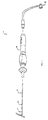
- FIG. 1 shows a catheter 10 comprising an elongated catheter body 12 having proximal and distal ends, a control handle 16 attached at the proximal end of the catheter body, an intermediate section 14 attached at the distal end of the catheter body, and a mapping assembly 17 attached to the intermediate section.
- the catheter body 12 comprises an elongated tubular construction having a single, axial or central lumen 18, although multiple lumens can be provided if desired.
- the catheter body 12 is flexible, i.e., bendable, but substantially non-compressible along its length.
- the catheter body 12 can be of any suitable construction and made of any suitable material.
- a presently preferred construction comprises an outer wall 20 made of polyurethane or polyether block amide such as that sold under the trade mark PEBAX.
- the outer wall 20 comprises an imbedded braided mesh of stainless steel or the like to increase torsional stiffness of the catheter body 12 so that, when the control handle 16 is rotated, the intermediate section 14 of the catheter 10 will rotate in a corresponding manner.
- the outer diameter of the catheter body 12 is not critical, but is preferably no more than about 8 french, more preferably about 7 french.
- the thickness of the outer wall 20 is not critical, but is thin enough so that the central lumen 18 can accommodate a puller wire, lead wires, and any other desired wires, cables or tubes, as discussed in more detail below.
- the inner surface of the outer wall 20 may be lined with a stiffening tube (not shown) to provide improved torsional stability.
- a particularly preferred catheter has an outer wall 20 with an outer diameter of from about 2.28 to about 24 mm (0.090 to 0.94 inch) and an inner diameter of from about 1.5 mm to about 1.65 mm (0.061 to 0.065 inch).
- the intermediate section 14 comprises a short section of tubing 22 having three off-axis lumens, a first lumen 30 that carries a first puller wire 64, a second lumen 32 that carries a second puller wire 65 and a third lumen 34 that carries electrode lead wires 50 and a support member 24 for the mapping assembly 17, all of which are discussed further below.
- the tubing 22 is made of a suitable non-toxic material that is preferably more flexible than the catheter body 12.
- a presently preferred material for the tubing 22 is braided polyurethane, i.e., polyurethane with an embedded mesh of braided stainless steel or the like.
- the size of each lumen is not critical, but is sufficient to house the lead wires, puller wire or support member.
- the useful length of the catheter i.e., that portion that can be inserted into the patient excluding the mapping assembly 17, can vary as desired. Preferably the useful length ranges from about 110 cm to about 120 cm.
- the length of the intermediate section 14 is a relatively small portion of the useful length, and preferably ranges from about 3.5 cm to about 10 cm, more preferably from about 5 cm to about 6.5 cm.
- FIG. 2 A preferred means for attaching the catheter body 12 to the intermediate section 14 is illustrated in FIG. 2.
- the proximal end of the intermediate section 14 comprises an outer circumferential notch 26 that receives the inner surface of the outer wall 22 of the catheter body 12.
- the intermediate section 14 and catheter body 12 are attached by glue or the like.
- the catheter body 12 and intermediate section 14 can be formed of a single unitary piece of tubing. Such a design would be useful, for example, where the catheter body and intermediate section have the same number of lumens.
- a spacer (not shown) can be located within the catheter body 12 between the distal end of the stiffening tube (if provided) and the proximal end of the intermediate section 14.
- the spacer provides a transition in flexibility at the junction of the catheter body 12 and intermediate section 14, which allows this junction to bend smoothly without folding or kinking.
- a catheter having such a spacer is described in US-5964757.
- mapping assembly At the distal end of the intermediate section 14 is a mapping assembly, as shown in FIGs. 3 to 7.
- the mapping assembly comprises a non-conductive covering 28 having two off-axis lumens 114 and 116 extending therethrough.
- the distal end of the support member 24, which gives shape to the mapping assembly 17, extends through the first lumen 114 of the non-conductive covering 28.
- the support member 24 can be eliminated and the non-conductive covering 28 can be designed to provide the desired shape for the mapping assembly 17.
- the mapping assembly 17 has a generally straight proximal region 38, a generally circular main region 39 and a generally straight distal region 40.
- the proximal region 38 is mounted on the intermediate section 14, as described in more detail below, so that its axis is generally parallel to the axis of the intermediate section.
- the proximal region 38 preferably has an exposed length, e.g., not contained within the intermediate section 14, ranging from about 3 mm to about 12 mm, more preferably about 3 mm to about 8 mm, still more preferably about 5 mm, but can vary as desired.
- the generally circular main region 39 does not form a flat circle, but is very slightly helical, as shown in FIGs.4 to 6.
- the main region 39 has an outer diameter preferably ranging from about 8 mm to about 35 mm, more preferably from about 12 mm to about 20 mm, still more preferably about 15 mm.
- the transition region 41 of the straight proximal region 38 and generally circular main region 39 is slightly curved and formed such that, when viewed from the side with the proximal region at the top of the circular main region as shown in FIG. 5, the proximal region (along with the intermediate section 14) forms an angle ⁇ with the curved region ranging from about 75° to about 95°, preferably from about 83° to about 93°, more preferably about 87°.
- the main region 39 can curve in a clockwise direction, as shown in FIG. 5, or a counterclockwise direction, as shown in FIG. 6.
- the proximal region (along with the intermediate section 14) forms an angle ⁇ with the main region ranging from about 90° to about 135°, preferably from about 100° to about 110°, more preferably about 105°.
- the support member 24 is made of a material having shape-memory, i.e., that can be straightened or bent out of its original shape upon exertion of a force and is capable of substantially returning to its original shape upon removal of the force.
- a particularly preferred material for the support member 24 is a nickel/titanium alloy. Such alloys typically comprise about 55% nickel and 45% titanium, but may comprise from about 54% to about 57% nickel with the balance being titanium.
- a preferred nickel/titanium alloy is Nitinol, which has excellent shape memory, together with ductility, strength, corrosion resistance, electrical resistivity and temperature stability.
- the non-conductive covering 28 can be made of any suitable material, and is preferably made of a biocompatible plastic such as polyurethane or PEBAX
- a series of ring electrodes 36 are mounted on the non-conductive covering 28 of the generally circular main region 39 of the mapping assembly 17.
- the ring electrodes 36 can be made of any suitable solid conductive material, such as platinum or gold, preferably a combination of platinum and iridium, and mounted onto the non-conductive covering 28 with glue or the like.
- the ring electrodes can be formed by coating the non-conductive covering 28 with an electrically conducting material, like platinum, gold and/or iridium. The coating can be applied using sputtering, ion beam deposition or an equivalent technique.
- each ring electrode 36 is mounted by first forming a hole in the non-conductive covering 28.
- An electrode lead wire 50 is fed through the hole, and the ring electrode 36 is welded in place over the lead wire and non-conductive covering 28.
- the lead wires 50 extend between the non-conductive covering 28 and the support member 24.
- the number of ring electrodes 36 on the assembly can vary as desired. Preferably the number of ring electrodes ranges from about six to about twenty, more preferably from about eight to about twelve. In a particularly preferred embodiment, the assembly carries ten ring electrodes.
- the ring electrodes 36 are preferably approximately evenly spaced around the generally circular main region 39, as best shown in FIG. 7. In a particularly preferred embodiment, a distance of approximately 5 mm is provided between the centres of the ring electrodes 36.
- FIGs. 7 and 8 show a particularly preferred electrode arrangement.
- the generally circular main region 39 is very slightly helical, although FIGS. 7 and 8 depict the main region as a flat circle, as it would generally appear when viewed from the distal end of the catheter.
- the generally straight distal region 40 forms a tangent relative to the generally circular main region 39 and contacts the main region at a tangent point 43.
- a first electrode 36a is provided, which is the electrode that is on the generally circular main region 39 closest to the proximal region 38.
- a second electrode 36b is provided, which is the electrode that is on the generally circular main region 39 closest to the distal region 40.
- the first electrode 36a is positioned along the circumference of the generally circular main region 39 at a distance ⁇ of no more than about 55° from the tangent point, more preferably no more than about 48° from the tangent point, still more preferably from about 15° to about 36° from the tangent point.
- the second electrode 36b is positioned along the circumference of the generally circular main region 39 at a distance ⁇ of no more than about 55° degrees from the tangent point, more preferably no more than about 48° from the tangent point, still more preferably from about 15° to about 36° from the tangent point.
- the first electrode 36a is positioned along the circumference of the generally circular main region 39 at a distance ⁇ of no more than 100° from the second electrode 36b, preferably no more than 80° from the second electrode, still more preferably from about 30° to about 75° from the second electrode.
- additional electrodes could be mounted along the intermediate section 14, the generally straight proximal section 39, the transition region 41, and/or generally straight distal region 40.
- the junction of the intermediate section 14 and mapping assembly 17 is shown in FIG. 3.
- the non-conductive covering 28 is attached to the tubing 22 of the intermediate section by glue or the like.
- the support member 24 extends from the third lumen 34 into the first lumen 114 of the non-conductive covering 28 and through the generally circular main region 39 of the mapping assembly.
- the proximal end of the support member 24 terminates a short distance within the third lumen 34 of the intermediate section 14, approximately about 5 mm, so as not to adversely affect the ability of the intermediate section to deflect. However, if desired, the proximal end of the support member 24 can extend into the catheter body 12.
- the lead wires 50 attached to the ring electrodes 36 also extend through the first lumen 114 in the non-conductive covering 28, the third lumen 34 of the intermediate section 14, the central lumen 18 of the catheter body 12, and the control handle 16, and terminate at their proximal end in the connector 37, which is connected to a source of RF energy (not shown).
- the portion of the lead wires 50 extending through the central lumen 18 of the catheter body 12, control handle 16 and proximal end of the intermediate section 14 are enclosed within a protective sheath 62, which can be made of any suitable material, preferably polyimide.
- the protective sheath 62 is anchored at its distal end to the proximal end of the intermediate section 14 by gluing it in the third lumen 34 with polyurethane glue or the like.
- the generally straight distal region 40 of the mapping assembly 17 is provided with an atraumatic design to prevent the distal end of the mapping assembly from penetrating tissue.
- the distal region 40 comprises a tightly wound coil spring 44 made, for example, of stainless steel, such as the mini guidewire commercially available from Cordis Corporation (Miami, Florida) or a coil having a 0.11 mm (0.0045 inch) wire size and a 0.23 mm (0.009 inch) inner diameter, such as that commercially available from Microspring.
- the coil spring 44 extends through the first lumen 114 of the non-conductive covering 28 and is mounted at its proximal end in a short piece of tubing 45 with polyurethane glue or the like, which is then glued or otherwise anchored within the non-conductive covering.
- the tubing 45 is less flexible than the non-conductive covering 28 but more flexible than that support member 24 to provide a transition in flexibility along the length of the mapping assembly 17.
- the distal end of the distal region 40 is capped, preferably with polyurethane glue 46, to prevent body fluids from entering the mapping assembly 17.
- the generally straight distal region 40 has a length of about 12.7 mm (0.5 inch), but can be any desired length, for example, ranging from about 6.35 to about 25.4 mm (0.25 to 1.0 inch).
- the generally straight distal region 40 is preferably sufficiently long to serve as an anchor for introducing the catheter into a guiding sheath, as discussed in more detail below, because the mapping assembly 17 must be straightened upon introduction into the sheath. Without having the generally straight distal region 40 as an anchor, the mapping assembly 17 has a tendency to pull out of the guiding sheath upon its introduction into the guiding sheath.
- the distal region 40 can be formed, at least in part, of a radiopaque material to aid in the positioning of the mapping assembly 17 under fluoroscopy.
- the first puller wire 64 is provided for deflection of the intermediate section 14.
- the second puller wire 65 is provided for contracting the mapping assembly 17.
- Each puller wire 64 and 65 extends from the control handle 16, through the central lumen 18 of the catheter body 12 and into the first and second lumens 30 and 32 of the intermediate section 14, respectively.
- the second puller wire 65 then extends into the second lumen 116 of the mapping assembly 17.
- the proximal end of the first puller wire 64 is anchored within the control handle 16, and the distal end of the first puller wire is anchored in the intermediate section 14.
- the proximal end of the second puller wire 65 is anchored within the control handle 16, and the distal end of the second puller wire is anchored in the distal end of the mapping assembly 17.
- Each puller wire 64 and 65 is made of any suitable metal, such as stainless steel or a nickel titanium based shape memory alloy such as Nitinol. Preferably each puller wire 64 and 65 has a coating (not shown), such as a coating of Teflon or the like. Each puller wire 64 and 65 has a diameter preferably ranging from about 0.15 to about 0.25 mm (0.006 to 0.010 inch).
- the first puller wire 64 is anchored at its distal end to the distal end of the intermediate section 14 using a T-shaped anchor, as shown in FIG. 3, which comprises a short piece of tubular stainless steel 80, e.g., hypodermic stock, which is fitted over the distal end of the first puller wire 64 and crimped to fixedly secure it to the first puller wire.
- the distal end of the tubular stainless steel 80 is fixedly attached, e.g., by welding, to a cross-piece 82 formed of stainless steel ribbon or the like.
- the cross-piece 82 sits beyond the distal end of the first lumen 30.
- the cross-piece 82 is larger than the lumen opening and, therefore, cannot be pulled through the opening.
- the distal end of the first lumen 30 is then filled with glue or the like, preferably a polyurethane glue.
- the first puller wire 64 extends through a plastic, preferably a polytetrafluoroethylene such as that sold under the trade mark Teflon, puller wire sheath (not shown), which prevents the first puller wire 64 from cutting into the wall of the intermediate section 14 when the intermediate section is deflected.
- the first puller wire 64 could be anchored to the side wall of the intermediate section 14 in a similar manner, where the T-shaped anchor extends into a notch in the side wall rather than beyond the distal end of the first lumen 30.
- a plastic preferably a polytetrafluoroethylene such as that sold under the trade mark Teflon, puller wire sheath (not shown)
- the first puller wire 64 could be anchored to the side wall of the intermediate section 14 in a similar manner, where the T-shaped anchor extends into a notch in the side wall rather than beyond the
- the second puller wire 65 is anchored in the distal end of the second lumen 116 of the mapping assembly in a manner similar to the first puller wire 64.
- a T-shaped anchor is mounted on the distal end of the second puller wire 65, extends into a notch in the side wall of the non-conductive covering 28, and is held in place with polyurethane glue or the like. Any other suitable method for anchoring the puller wires 64 and 65 could also be used.
- each compression coil 66 is situated within the catheter body 12, each in surrounding relation to a corresponding puller wire 64 and 65.
- Each compression coil 66 extends from the proximal end of the catheter body 12 to the proximal end of the intermediate section 14.
- the compression coils 66 are made of any suitable metal, preferably stainless steel.
- Each compression coil 66 is tightly wound on itself to provide flexibility, i.e., bending, but to resist compression.
- the inner diameter of each compression coil 66 is preferably slightly larger than the diameter of the corresponding puller wire 64 and 65.
- the polymer (especially PTFE) coatings on the puller wire 64 allow them to slide freely within the compression coils 66.
- the outer surfaces of the compression coil 66 are covered by flexible, non-conductive sheathes 68, e.g., made of polyimide tubing.
- Each compression coil 66 is anchored at its proximal end to the outer wall 20 of the catheter body 12 by proximal glue joint 70 and at its distal end to the intermediate section 14 by distal glue joint 72.
- Both glue joints 70 and 72 preferably comprise polyurethane glue or the like.
- the glue may be applied by means of a syringe or the like through a hole made between the outer surface of the catheter body 12 and the central lumen 18. Such a hole may be formed, for example, by a needle or the like that punctures the outer wall 20 of the catheter body 12 which is heated sufficiently to form a permanent hole.
- the glue is then introduced through the hole to the outer surfaces of the compression coils 66 and wicks around the outer circumferences to form a glue joint about the entire circumferences of the compression coils.
- the compression coils 66 could be anchored at different longitudinal locations or eliminated altogether.
- the control handle 16 comprises a generally tubular housing 86 having a longitudinal axis and proximal and distal ends and a generally tubular core 90 extending within the housing along its longitudinal axis.
- the core 90 is a separate piece that is fixedly attached to the handle housing 86 for ease in manufacturing, although the core could be formed integral with the housing if desired.
- the core 90 has proximal and distal ends that extend beyond and outside the proximal and distal ends, respectively, of the housing 86.
- the catheter body 12 is fixedly attached to the distal end of the core 90 by means of a glue joint and shrink sleeve, as is generally known to those skilled in the art, or by any other suitable method.
- the puller wires 64 and 65, lead wires 50 and any other wires, tubes or cables that extend through the catheter body 12 extend through a lumen or passage 88 in the core 90, although the lead wires 50 are not shown in FIGs. 9 to 11 for clarity.
- An elongated slot 102 extends through a portion of the length of the core 90.
- a piston 84 is mounted within the housing 86 in surrounding relation to the core 90.
- the piston 84 has a tubular distal end 85 and a semicircular proximal end 87.
- the semicircular proximal end 87 is shaped so that its inner surface fits generally against the tubular core 102.
- the precise shape of the piston 84 is not critical to the invention.
- a portion of the distal end 85 of the piston 84 extends outside the distal end of the handle housing 86.
- the distal end 85 of the piston 84 comprises threading 89 to provide a means for mounting a thumb control 92, having corresponding internal threading (not shown), onto the piston.
- the proximal end of the first puller wire 64 is anchored to the piston 84 by any suitable method.
- the proximal end of the piston 84 comprises a generally rectangular opening 118 having a slanted edge 119.
- the opening 118 extends through a wall of the piston 84.
- a channel 121 which only extends a part of the way through the wall of the piston 84, is provided proximal the opening 118.
- a small groove 122 having a width less than that of the channel 121 connects the channel to the opening 118.
- the first puller wire 64 extends through the lumen 88 in the core 90, through the slot 102 in the core, through the opening 118 in the piston 84, through the small groove 122, and into the channel 121.
- the first puller wire 64 is anchored in the channel 121 by means of a puller wire anchor 124, which preferably comprises a short piece of hypodermic stock that is fixedly attached, e.g., by crimping, to the proximal end of the first puller wire 64 after it has passed through the small groove 122.
- the puller wire anchor 124 has a diameter greater than the width of the small groove 122 and thus prevents the proximal end of the first puller wire 64 from being pulled through the small groove.
- the length of the opening 118 is limited such that, when the piston 84 is in its most distal position relative to the housing 86, the opening does not extend outside the housing. However, the opening 118 is preferably long enough so that the first puller wire 64 extends through the opening at an angle rather than bending or kinking.
- proximal movement of the piston 84 relative to handle housing 86 and core 90 causes proximal movement of the piston and first puller wire 64 relative to the catheter body 12.
- Such movement results in deflection of the intermediate section 14 in the direction of the side of the first off-axis lumen 30 through which the first puller wire extends.
- the second puller wire 65 is anchored at its proximal end to a threaded slide 100, which is disposed in the slot 102 of the core 90, by any suitable method.
- the slide 100 comprises a generally solid, generally rectangular piece of plastic with threading 101 along one surface.
- the slide 100 has a generally rectangular hole 103 in which the distal end of the second puller anchor 65 in anchored with a puller wire anchor 125, in a manner similar to the first puller wire 64, discussed above.
- the threaded slide 100 is mounted within the slot 102 in the core 90 such that the threaded slide is prevented from rotating, but is able to move longitudinally within the slot, thus producing a relative lateral motion between the threaded slide and the core.
- the handle housing 86 has a window 104, through which the threaded surface 101 of the threaded slide 100 protrudes when the handle is assembled.
- the window has first and second window edges 118 and 120, which limit the lateral movement of the threaded slide 100.
- a threaded sleeve 98 is mounted between first and second shoulders 106 and 108 on the handle housing 86.
- the threaded sleeve 98 has internal threading that engages the threads 101 of the threaded slide 100, such that rotation of the threaded sleeve causes the threaded slide to move longitudinally within the slot 102 in the core 90.
- Other arrangements for slidably mounting the threaded slide 100 within the handle housing 86 could also be used in accordance with the invention.
- the threaded slide 100 could be mounted over or around the core 90 instead of within a slot in the core.
- the proximal end of the second puller wire 65 is attached to the threaded slide 100 and the core 90 is attached to the catheter body 12, longitudinal movement of the threaded slide relative to the core results in corresponding movement of the second puller wire relative to the catheter body. Therefore, when the threaded sleeve 98 is rotated, the second puller wire 65 moves proximally relative to the catheter body 12, thus causing the straight distal region 40 of the mapping assembly 17 to also move relative to the catheter body and arc proximally or deflect. The deflection of the straight distal region 40 of the mapping assembly 17, in turn, causes the circular main region 39 of the mapping assembly to contract to thereby have a smaller diameter.
- the threaded sleeve 98 has a longitudinal slit and comprises a flexible material, such as delryn.
- the sleeve is separated along the slit and fit over the housing, such that the sleeve is disposed between the shoulders 106 and 108 of the handle housing.
- the threaded sleeve 98 may be formed from two halves that are fit over the housing 86 and then affixed together, such as by weld, adhesive, a screw, a rivet or the like.
- a gripping sleeve 112 is mounted over the threaded sleeve 98 to aid in rotating the sleeve and provide comfort to the user.
- the gripping sleeve 112 may comprise a high friction surface, such as rubber.
- the gripping sleeve 112 also aides in holding the threaded sleeve 98 together when the sleeve is assembled on the handle housing 86.
- the threaded sleeve 98 goes around the entire circumference of the handle housing 86. If desired the threaded sleeve 98 could be replaced with another rotatable member that extends around only a part of the circumference of the handle housing 86.
- a fastener (not shown) can be provided to maintain the handle housing 86 in place over the core 90.
- a fastener (not shown) can be provided to maintain the handle housing 86 in place over the core 90.
- a suitable guiding sheath is inserted into the patient with its distal end positioned at a desired mapping location.
- An example of a suitable guiding sheath for use in connection with the present invention is the PrefaceTM Braiding Guiding Sheath, commercially available from Cordis Webster (Diamond Bar, California).
- the distal end of the sheath is guided into one of the atria.
- a catheter in accordance with the present invention is fed through the guiding sheath until its distal end extends out of the distal end of the guiding sheath.
- the mapping assembly 17 is straightened to fit through the sheath.
- mapping assembly 17 is then inserted into a pulmonary vein or other tubular region (such as the coronary sinus, superior vena cava, or inferior vena cava) so that the outer circumference of the generally circular main region 39 of the assembly is in contact with a circumference inside the tubular region.
- a pulmonary vein or other tubular region such as the coronary sinus, superior vena cava, or inferior vena cava
- the outer circumference of the generally circular main region 39 of the assembly is in contact with a circumference inside the tubular region.
- at least about 50%, more preferably at least about 70%, and still more preferably at least about 80% of the circumference of the generally circular main region is in contact with a circumference inside the tubular region.
- the circular arrangement of the electrodes 36 permits measurement of the electrical activity at that circumference of the tubular structure so that ectopic beats between the electrodes can be identified.
- the size of the generally circular main region 39 permits measurement of electrical activity along a diameter of a pulmonary vein or other tubular structure of or near the heart because the circular main region has a diameter generally corresponding to that of a pulmonary vein or the coronary sinus. Additionally, because the main region 39 preferably does not form a flat circle, but instead is somewhat helical, as shown in FIG. 4, it is easier for the user to guide the mapping assembly 17 into a tubular region. If the circumference of the main region 39 of the mapping assembly 17 is larger than the circumference of the structure to be mapped, the mapping assembly can be contracted by longitudinal movement of the second puller wire 65 using the control handle 16, as described above.
- the inventive handle is not limited to the above-described catheter design.
- the handle is also particularly useful for bi-directional catheters and other catheters having two puller wires for deflection of the distal end of the catheter body, i.e., the intermediate section.
- Such catheters are described in US-6171277, US-6183463, US-6198974, US-6210407 and US-6267746, and in the European patent applications which claim priority from US Patent Applications Serial Nos. 09/822,087, entitled “Steerable Catheter with a Control Handle Having a Pulley Mechanism", and 09/846,732, entitled “Asymmetrical Bidirectional Steerable Catheter".
- Other uses for the handle of the invention would be recognized by one skilled in the art.
Abstract
Description
- The present invention is directed to a dual-function catheter handle for manipulating two different control wires.
- Electrode catheters have been in common use in medical practice for many years. They are used to stimulate and map electrical activity in the heart and to ablate sites of aberrant electrical activity.
- In use, the electrode catheter is inserted into a major vein or artery, e.g., femoral artery, and then guided into the chamber of the heart which is of concern. Within the heart, the ability to control the exact position and orientation of the catheter tip is critical and largely determines how useful the catheter is.
- Steerable catheters are generally well-known. For example, US-Re.34502 describes a catheter having a control handle comprising a housing having a piston chamber at its distal end. A piston is mounted in the piston chamber and is afforded lengthwise movement. The proximal end of the catheter body is attached to the piston. A puller wire is attached to the housing and extends through the piston and through the catheter body. The distal end of the puller wire is anchored in the tip section of the catheter. In this arrangement, lengthwise movement of the piston relative to the housing results in deflection of the distal end of the catheter body. The design described in US-Re.34502 is generally limited to a catheter having a single puller wire.
- Some catheter designs require more than one puller wire. For example, if a bidirectional catheter is desired, i.e., a catheter that can be deflected in more than one direction without rotating the catheter body, more than one puller wire becomes necessary. Catheters having two or more puller wires and handles for controlling the multiple puller wires are disclosed, for example, in US-6171277 and US-6183463. However, these catheters include handles whereby simultaneous proximal movement of the puller wires relative to the catheter body is prohibited, which is desirable for certain applications. However, for other applications, it is desirable to simultaneously move the puller wires proximally relative to the catheter body.
- The present invention is directed to a dual function catheter handle that is capable of simultaneously moving two control or puller wires relative to the body of the catheter and also to a catheter incorporating the handle. In one embodiment, the invention is directed to a catheter handle comprising a handle housing having proximal and distal ends and a generally hollow interior. A first moveable member is provided having a proximal end mounted in the interior of the handle housing and a distal end extending outside the handle housing. The first moveable member is longitudinally moveable relative to the handle housing. A second moveable member is mounted in the interior of the handle housing and longitudinally moveable relative to the handle housing. A rotatable member is mounted on the handle housing so that rotation of the rotatable member causes longitudinal movement of the second moveable member.
- In a particularly preferred embodiment, the invention is directed to a catheter handle comprising a handle housing having proximal and distal ends and a generally hollow interior. A core is mounted in the interior of the handle housing, the core having a longitudinal slot therethrough. A first moveable member is provided having a proximal end mounted in the interior of the handle housing and a distal end extending outside the handle housing. The first moveable member is longitudinally moveable relative to the handle housing. A second moveable member is mounted in the longitudinal slot of the core and is longitudinally moveable relative to the core and handle housing. The second moveable member has a threaded surface. A rotatable member is mounted on the handle housing and has a threaded inner surface that mates with the threaded surface of the second moveable member. Rotation of the rotatable member causes longitudinal movement of the second moveable member.
- In another embodiment, the invention is directed to a catheter incorporating the handle of the invention. The catheter comprises an elongated, flexible catheter body having proximal and distal ends and a lumen extending therethrough. An intermediate section is mounted at the distal end of the catheter body. The intermediate section has proximal and distal ends and first and second off-axis lumens extending therethrough. The intermediate section can be separate from or integral with the catheter body. A handle as described above is mounted at the proximal end of the catheter body. The catheter body is attached to the handle housing, either directly or indirectly, for example, by mounting it to the core. A first puller wire extends through the catheter body and first off-axis lumen of the intermediate section. The first puller wire has a proximal end anchored to the first moveable member of the handle and a distal end anchored at or near the distal end of the catheter. The distal end of the catheter to which the puller wires are anchored can include any part of the distal end that is inserted into the heart, such as the intermediate section or another ablation or mapping assembly that is mounted onto the intermediate section. A second puller wire extends through the catheter body and second off-axis lumen of the intermediate section. The second puller wire has a proximal end anchored to the second moveable member of the handle and a distal end anchored at or near the distal end of the catheter. In a particularly preferred embodiment, the distal end of the first puller wire is anchored to the intermediate section and the catheter further comprises a generally circular mapping assembly mounted on distal end of the intermediate section, wherein the distal end of the second puller wire extends through an off-axis lumen of them mapping assembly and is anchored at or near the distal end of the mapping assembly for contraction of the mapping assembly.
- In another aspect, the invention includes a catheter handle comprising:
- a handle housing having proximal and distal ends and a generally hollow interior;
- a core mounted in the interior of the handle housing, the core having a longitudinal slot therethrough;
- a first moveable member having a proximal end mounted in the interior of the handle housing and a distal end extending outside the handle housing, the first moveable member being longitudinally moveable relative to the handle housing;
- a second moveable member mounted in the longitudinal slot of the core and longitudinally moveable relative to the core and handle housing, the second moveable member having a threaded surface; and
- a rotatable member mounted on the handle housing and having a threaded inner surface that mates with the threaded surface of the second moveable member, whereby rotation of the rotatable member causes longitudinal movement of the second moveable member; wherein the first moveable member and second moveable member are capable of simultaneously moving proximally relative to the handle housing.
-
- In a further aspect, the invention includes a catheter comprising:
- an elongated, flexible catheter body having proximal and distal ends and a lumen extending therethrough;
- an intermediate section at the distal end of the catheter body having proximal and distal ends and first and second off-axis lumens extending therethrough;
- a handle according to claim 1 mounted at the proximal end of the catheter body, whereby the catheter body is attached to the handle housing;
- a first puller wire extending through the catheter body and first off-axis lumen of the intermediate section, having a proximal end anchored to the first moveable member of the handle, and having a distal end anchored at or near the distal end of the catheter; and
- a second puller wire extending through the catheter body and second off-axis lumen of the intermediate section, having a proximal end anchored to the second moveable member of the handle, and having a distal end anchored at or near the distal end of the catheter.
-
- Embodiments of the invention will now be described by way of example with reference to the accompanying drawings, in which:
- FIG. 1 is a perspective view of a catheter according to the invention.
- FIG. 2 is a side cross-sectional view of the catheter body of a catheter according to the invention.
- FIG. 3 is a side cross-sectional view of the junction of the intermediate section and mapping assembly of a catheter according to the invention.
- FIG. 4 is a schematic perspective view of the mapping assembly according to the invention.
- FIG. 5 is a side view of the mapping assembly according to the invention in a clockwise formation.
- FIG. 6 is a side view of the mapping assembly according to the invention in a counterclockwise formation rotated 90° relative to the assembly depicted in FIG. 5.
- FIG. 7 is a schematic view of the mapping assembly according to the invention.
- FIG. 8 is a schematic view of the mapping assembly according to the invention depicting the relationship between the first and last electrodes.
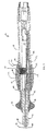
- FIG. 9 is a side section view of a catheter handle according to the invention.
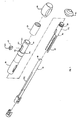
- FIG. 10 is a cut away view of the catheter handle of FIG. 9.
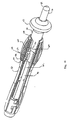
- FIG. 11 is a perspective view of an assembly of the catheter handle of FIG. 9.
- FIG. 12 is a perspective view of the piston of the catheter handle of FIG. 9.
-
- Referring to the drawings, FIG. 1 shows a
catheter 10 comprising anelongated catheter body 12 having proximal and distal ends, acontrol handle 16 attached at the proximal end of the catheter body, anintermediate section 14 attached at the distal end of the catheter body, and amapping assembly 17 attached to the intermediate section. - With reference to FIG. 2, the
catheter body 12 comprises an elongated tubular construction having a single, axial or central lumen 18, although multiple lumens can be provided if desired. Thecatheter body 12 is flexible, i.e., bendable, but substantially non-compressible along its length. Thecatheter body 12 can be of any suitable construction and made of any suitable material. A presently preferred construction comprises anouter wall 20 made of polyurethane or polyether block amide such as that sold under the trade mark PEBAX. Theouter wall 20 comprises an imbedded braided mesh of stainless steel or the like to increase torsional stiffness of thecatheter body 12 so that, when the control handle 16 is rotated, theintermediate section 14 of thecatheter 10 will rotate in a corresponding manner. - The outer diameter of the
catheter body 12 is not critical, but is preferably no more than about 8 french, more preferably about 7 french. Likewise the thickness of theouter wall 20 is not critical, but is thin enough so that the central lumen 18 can accommodate a puller wire, lead wires, and any other desired wires, cables or tubes, as discussed in more detail below. If desired, the inner surface of theouter wall 20 may be lined with a stiffening tube (not shown) to provide improved torsional stability. A particularly preferred catheter has anouter wall 20 with an outer diameter of from about 2.28 to about 24 mm (0.090 to 0.94 inch) and an inner diameter of from about 1.5 mm to about 1.65 mm (0.061 to 0.065 inch). - As shown in FIGs. 2 and 3, the
intermediate section 14 comprises a short section oftubing 22 having three off-axis lumens, afirst lumen 30 that carries afirst puller wire 64, asecond lumen 32 that carries asecond puller wire 65 and athird lumen 34 that carrieselectrode lead wires 50 and asupport member 24 for themapping assembly 17, all of which are discussed further below. Thetubing 22 is made of a suitable non-toxic material that is preferably more flexible than thecatheter body 12. A presently preferred material for thetubing 22 is braided polyurethane, i.e., polyurethane with an embedded mesh of braided stainless steel or the like. The size of each lumen is not critical, but is sufficient to house the lead wires, puller wire or support member. - The useful length of the catheter, i.e., that portion that can be inserted into the patient excluding the
mapping assembly 17, can vary as desired. Preferably the useful length ranges from about 110 cm to about 120 cm. The length of theintermediate section 14 is a relatively small portion of the useful length, and preferably ranges from about 3.5 cm to about 10 cm, more preferably from about 5 cm to about 6.5 cm. - A preferred means for attaching the
catheter body 12 to theintermediate section 14 is illustrated in FIG. 2. The proximal end of theintermediate section 14 comprises an outercircumferential notch 26 that receives the inner surface of theouter wall 22 of thecatheter body 12. Theintermediate section 14 andcatheter body 12 are attached by glue or the like. - Alternatively, the
catheter body 12 andintermediate section 14 can be formed of a single unitary piece of tubing. Such a design would be useful, for example, where the catheter body and intermediate section have the same number of lumens. - If desired, a spacer (not shown) can be located within the
catheter body 12 between the distal end of the stiffening tube (if provided) and the proximal end of theintermediate section 14. The spacer provides a transition in flexibility at the junction of thecatheter body 12 andintermediate section 14, which allows this junction to bend smoothly without folding or kinking. A catheter having such a spacer is described in US-5964757. - At the distal end of the
intermediate section 14 is a mapping assembly, as shown in FIGs. 3 to 7. The mapping assembly comprises anon-conductive covering 28 having two off-axis lumens support member 24, which gives shape to themapping assembly 17, extends through thefirst lumen 114 of thenon-conductive covering 28. However, if desired, thesupport member 24 can be eliminated and the non-conductive covering 28 can be designed to provide the desired shape for themapping assembly 17. - The
mapping assembly 17 has a generally straightproximal region 38, a generally circularmain region 39 and a generally straightdistal region 40. Theproximal region 38 is mounted on theintermediate section 14, as described in more detail below, so that its axis is generally parallel to the axis of the intermediate section. Theproximal region 38 preferably has an exposed length, e.g., not contained within theintermediate section 14, ranging from about 3 mm to about 12 mm, more preferably about 3 mm to about 8 mm, still more preferably about 5 mm, but can vary as desired. - The generally circular
main region 39 does not form a flat circle, but is very slightly helical, as shown in FIGs.4 to 6. Themain region 39 has an outer diameter preferably ranging from about 8 mm to about 35 mm, more preferably from about 12 mm to about 20 mm, still more preferably about 15 mm. Thetransition region 41 of the straightproximal region 38 and generally circularmain region 39 is slightly curved and formed such that, when viewed from the side with the proximal region at the top of the circular main region as shown in FIG. 5, the proximal region (along with the intermediate section 14) forms an angle α with the curved region ranging from about 75° to about 95°, preferably from about 83° to about 93°, more preferably about 87°. Themain region 39 can curve in a clockwise direction, as shown in FIG. 5, or a counterclockwise direction, as shown in FIG. 6. When theassembly 17 is turned 90°, as shown in FIG. 6, so that thetransition region 41 is near the centre of the main region, the proximal region (along with the intermediate section 14) forms an angle β with the main region ranging from about 90° to about 135°, preferably from about 100° to about 110°, more preferably about 105°. - The
support member 24 is made of a material having shape-memory, i.e., that can be straightened or bent out of its original shape upon exertion of a force and is capable of substantially returning to its original shape upon removal of the force. A particularly preferred material for thesupport member 24 is a nickel/titanium alloy. Such alloys typically comprise about 55% nickel and 45% titanium, but may comprise from about 54% to about 57% nickel with the balance being titanium. A preferred nickel/titanium alloy is Nitinol, which has excellent shape memory, together with ductility, strength, corrosion resistance, electrical resistivity and temperature stability. Thenon-conductive covering 28 can be made of any suitable material, and is preferably made of a biocompatible plastic such as polyurethane or PEBAX - A series of
ring electrodes 36 are mounted on the non-conductive covering 28 of the generally circularmain region 39 of themapping assembly 17. Thering electrodes 36 can be made of any suitable solid conductive material, such as platinum or gold, preferably a combination of platinum and iridium, and mounted onto the non-conductive covering 28 with glue or the like. Alternatively, the ring electrodes can be formed by coating the non-conductive covering 28 with an electrically conducting material, like platinum, gold and/or iridium. The coating can be applied using sputtering, ion beam deposition or an equivalent technique. - In a preferred embodiment, each
ring electrode 36 is mounted by first forming a hole in thenon-conductive covering 28. Anelectrode lead wire 50 is fed through the hole, and thering electrode 36 is welded in place over the lead wire andnon-conductive covering 28. Thelead wires 50 extend between thenon-conductive covering 28 and thesupport member 24. - The number of
ring electrodes 36 on the assembly can vary as desired. Preferably the number of ring electrodes ranges from about six to about twenty, more preferably from about eight to about twelve. In a particularly preferred embodiment, the assembly carries ten ring electrodes. Thering electrodes 36 are preferably approximately evenly spaced around the generally circularmain region 39, as best shown in FIG. 7. In a particularly preferred embodiment, a distance of approximately 5 mm is provided between the centres of thering electrodes 36. - FIGs. 7 and 8 show a particularly preferred electrode arrangement. As explained above, the generally circular
main region 39 is very slightly helical, although FIGS. 7 and 8 depict the main region as a flat circle, as it would generally appear when viewed from the distal end of the catheter. The generally straightdistal region 40 forms a tangent relative to the generally circularmain region 39 and contacts the main region at atangent point 43. Afirst electrode 36a is provided, which is the electrode that is on the generally circularmain region 39 closest to theproximal region 38. Asecond electrode 36b is provided, which is the electrode that is on the generally circularmain region 39 closest to thedistal region 40. Preferably, thefirst electrode 36a is positioned along the circumference of the generally circularmain region 39 at a distance of no more than about 55° from the tangent point, more preferably no more than about 48° from the tangent point, still more preferably from about 15° to about 36° from the tangent point. Preferably thesecond electrode 36b is positioned along the circumference of the generally circularmain region 39 at a distance ω of no more than about 55° degrees from the tangent point, more preferably no more than about 48° from the tangent point, still more preferably from about 15° to about 36° from the tangent point. Preferably thefirst electrode 36a is positioned along the circumference of the generally circularmain region 39 at a distance γ of no more than 100° from thesecond electrode 36b, preferably no more than 80° from the second electrode, still more preferably from about 30° to about 75° from the second electrode. If desired, additional electrodes (not shown) could be mounted along theintermediate section 14, the generally straightproximal section 39, thetransition region 41, and/or generally straightdistal region 40. - The junction of the
intermediate section 14 andmapping assembly 17 is shown in FIG. 3. Thenon-conductive covering 28 is attached to thetubing 22 of the intermediate section by glue or the like. Thesupport member 24 extends from thethird lumen 34 into thefirst lumen 114 of thenon-conductive covering 28 and through the generally circularmain region 39 of the mapping assembly. The proximal end of thesupport member 24 terminates a short distance within thethird lumen 34 of theintermediate section 14, approximately about 5 mm, so as not to adversely affect the ability of the intermediate section to deflect. However, if desired, the proximal end of thesupport member 24 can extend into thecatheter body 12. - The
lead wires 50 attached to thering electrodes 36 also extend through thefirst lumen 114 in the non-conductive covering 28, thethird lumen 34 of theintermediate section 14, the central lumen 18 of thecatheter body 12, and the control handle 16, and terminate at their proximal end in the connector 37, which is connected to a source of RF energy (not shown). The portion of thelead wires 50 extending through the central lumen 18 of thecatheter body 12, control handle 16 and proximal end of theintermediate section 14 are enclosed within aprotective sheath 62, which can be made of any suitable material, preferably polyimide. Theprotective sheath 62 is anchored at its distal end to the proximal end of theintermediate section 14 by gluing it in thethird lumen 34 with polyurethane glue or the like. - The generally straight
distal region 40 of themapping assembly 17 is provided with an atraumatic design to prevent the distal end of the mapping assembly from penetrating tissue. In the depicted embodiment, thedistal region 40 comprises a tightly woundcoil spring 44 made, for example, of stainless steel, such as the mini guidewire commercially available from Cordis Corporation (Miami, Florida) or a coil having a 0.11 mm (0.0045 inch) wire size and a 0.23 mm (0.009 inch) inner diameter, such as that commercially available from Microspring. Thecoil spring 44 extends through thefirst lumen 114 of thenon-conductive covering 28 and is mounted at its proximal end in a short piece oftubing 45 with polyurethane glue or the like, which is then glued or otherwise anchored within the non-conductive covering. Thetubing 45 is less flexible than the non-conductive covering 28 but more flexible than thatsupport member 24 to provide a transition in flexibility along the length of themapping assembly 17. The distal end of thedistal region 40 is capped, preferably withpolyurethane glue 46, to prevent body fluids from entering themapping assembly 17. In the depicted embodiment, the generally straightdistal region 40 has a length of about 12.7 mm (0.5 inch), but can be any desired length, for example, ranging from about 6.35 to about 25.4 mm (0.25 to 1.0 inch). The generally straightdistal region 40 is preferably sufficiently long to serve as an anchor for introducing the catheter into a guiding sheath, as discussed in more detail below, because themapping assembly 17 must be straightened upon introduction into the sheath. Without having the generally straightdistal region 40 as an anchor, themapping assembly 17 has a tendency to pull out of the guiding sheath upon its introduction into the guiding sheath. Additionally, if desired, thedistal region 40 can be formed, at least in part, of a radiopaque material to aid in the positioning of themapping assembly 17 under fluoroscopy. - As noted above, two
puller wires first puller wire 64 is provided for deflection of theintermediate section 14. Thesecond puller wire 65 is provided for contracting themapping assembly 17. Eachpuller wire catheter body 12 and into the first andsecond lumens intermediate section 14, respectively. Thesecond puller wire 65 then extends into thesecond lumen 116 of themapping assembly 17. As described in more detail below, the proximal end of thefirst puller wire 64 is anchored within the control handle 16, and the distal end of the first puller wire is anchored in theintermediate section 14. Also as described further below, the proximal end of thesecond puller wire 65 is anchored within the control handle 16, and the distal end of the second puller wire is anchored in the distal end of themapping assembly 17. - Each
puller wire puller wire puller wire - In the depicted embodiment, the
first puller wire 64 is anchored at its distal end to the distal end of theintermediate section 14 using a T-shaped anchor, as shown in FIG. 3, which comprises a short piece of tubularstainless steel 80, e.g., hypodermic stock, which is fitted over the distal end of thefirst puller wire 64 and crimped to fixedly secure it to the first puller wire. The distal end of the tubularstainless steel 80 is fixedly attached, e.g., by welding, to across-piece 82 formed of stainless steel ribbon or the like. Thecross-piece 82 sits beyond the distal end of thefirst lumen 30. Thecross-piece 82 is larger than the lumen opening and, therefore, cannot be pulled through the opening. The distal end of thefirst lumen 30 is then filled with glue or the like, preferably a polyurethane glue. Within thefirst lumen 30 of theintermediate section 14, thefirst puller wire 64 extends through a plastic, preferably a polytetrafluoroethylene such as that sold under the trade mark Teflon, puller wire sheath (not shown), which prevents thefirst puller wire 64 from cutting into the wall of theintermediate section 14 when the intermediate section is deflected. Alternatively, thefirst puller wire 64 could be anchored to the side wall of theintermediate section 14 in a similar manner, where the T-shaped anchor extends into a notch in the side wall rather than beyond the distal end of thefirst lumen 30. Such a design is disclosed in US-6064908. - The
second puller wire 65 is anchored in the distal end of thesecond lumen 116 of the mapping assembly in a manner similar to thefirst puller wire 64. A T-shaped anchor is mounted on the distal end of thesecond puller wire 65, extends into a notch in the side wall of the non-conductive covering 28, and is held in place with polyurethane glue or the like. Any other suitable method for anchoring thepuller wires - In the depicted embodiment, two compression coils 66 are situated within the
catheter body 12, each in surrounding relation to acorresponding puller wire catheter body 12 to the proximal end of theintermediate section 14. The compression coils 66 are made of any suitable metal, preferably stainless steel. Each compression coil 66 is tightly wound on itself to provide flexibility, i.e., bending, but to resist compression. The inner diameter of each compression coil 66 is preferably slightly larger than the diameter of thecorresponding puller wire puller wire 64 allow them to slide freely within the compression coils 66. The outer surfaces of the compression coil 66 are covered by flexible, non-conductive sheathes 68, e.g., made of polyimide tubing. - Each compression coil 66 is anchored at its proximal end to the
outer wall 20 of thecatheter body 12 by proximal glue joint 70 and at its distal end to theintermediate section 14 by distal glue joint 72. Bothglue joints catheter body 12 and the central lumen 18. Such a hole may be formed, for example, by a needle or the like that punctures theouter wall 20 of thecatheter body 12 which is heated sufficiently to form a permanent hole. The glue is then introduced through the hole to the outer surfaces of the compression coils 66 and wicks around the outer circumferences to form a glue joint about the entire circumferences of the compression coils. If desired, the compression coils 66 could be anchored at different longitudinal locations or eliminated altogether. - Longitudinal movement of each of the
puller wires catheter body 12 is accomplished by suitable manipulation of the control handle 16. An embodiment of the control handle 16 according to the invention is shown in FIGs. 9 to 11. The control handle 16 comprises a generallytubular housing 86 having a longitudinal axis and proximal and distal ends and a generallytubular core 90 extending within the housing along its longitudinal axis. In the depicted embodiment, thecore 90 is a separate piece that is fixedly attached to thehandle housing 86 for ease in manufacturing, although the core could be formed integral with the housing if desired. Thecore 90 has proximal and distal ends that extend beyond and outside the proximal and distal ends, respectively, of thehousing 86. Thecatheter body 12 is fixedly attached to the distal end of the core 90 by means of a glue joint and shrink sleeve, as is generally known to those skilled in the art, or by any other suitable method. Thepuller wires lead wires 50 and any other wires, tubes or cables that extend through thecatheter body 12 extend through a lumen orpassage 88 in thecore 90, although thelead wires 50 are not shown in FIGs. 9 to 11 for clarity. Anelongated slot 102 extends through a portion of the length of thecore 90. - A
piston 84 is mounted within thehousing 86 in surrounding relation to thecore 90. Thepiston 84 has a tubular distal end 85 and a semicircular proximal end 87. The semicircular proximal end 87 is shaped so that its inner surface fits generally against thetubular core 102. The precise shape of thepiston 84 is not critical to the invention. When thehandle 16 is assembled, a portion of the distal end 85 of thepiston 84 extends outside the distal end of thehandle housing 86. The distal end 85 of thepiston 84 comprises threading 89 to provide a means for mounting athumb control 92, having corresponding internal threading (not shown), onto the piston. A preferred arrangement for mounting thethumb control 92 on thepiston 84 is described in European patent application which claims priority from US Patent Application Serial No. 09/546,310, entitled "Single Gear Drive Bi-Directional Control Handle for Steerable Catheter". With this design, the user can cause longitudinal movement of thepiston 84 relative to thehandle housing 86 by pushing or pulling the piston 84 (directly or via the thumb control 92). - The proximal end of the
first puller wire 64 is anchored to thepiston 84 by any suitable method. In the depicted embodiment, as shown in FIG. 12, the proximal end of thepiston 84 comprises a generallyrectangular opening 118 having a slantededge 119. Theopening 118 extends through a wall of thepiston 84. Achannel 121, which only extends a part of the way through the wall of thepiston 84, is provided proximal theopening 118. Asmall groove 122 having a width less than that of thechannel 121 connects the channel to theopening 118. Thefirst puller wire 64 extends through thelumen 88 in thecore 90, through theslot 102 in the core, through theopening 118 in thepiston 84, through thesmall groove 122, and into thechannel 121. Thefirst puller wire 64 is anchored in thechannel 121 by means of apuller wire anchor 124, which preferably comprises a short piece of hypodermic stock that is fixedly attached, e.g., by crimping, to the proximal end of thefirst puller wire 64 after it has passed through thesmall groove 122. Thepuller wire anchor 124 has a diameter greater than the width of thesmall groove 122 and thus prevents the proximal end of thefirst puller wire 64 from being pulled through the small groove. The length of theopening 118 is limited such that, when thepiston 84 is in its most distal position relative to thehousing 86, the opening does not extend outside the housing. However, theopening 118 is preferably long enough so that thefirst puller wire 64 extends through the opening at an angle rather than bending or kinking. - Because the
catheter body 12 is attached to thecore 90, proximal movement of thepiston 84 relative to handlehousing 86 andcore 90 causes proximal movement of the piston andfirst puller wire 64 relative to thecatheter body 12. Such movement results in deflection of theintermediate section 14 in the direction of the side of the first off-axis lumen 30 through which the first puller wire extends. - As shown in FIG. 9, the
second puller wire 65 is anchored at its proximal end to a threadedslide 100, which is disposed in theslot 102 of the core 90, by any suitable method. In the depicted embodiment, theslide 100 comprises a generally solid, generally rectangular piece of plastic with threading 101 along one surface. Theslide 100 has a generallyrectangular hole 103 in which the distal end of thesecond puller anchor 65 in anchored with apuller wire anchor 125, in a manner similar to thefirst puller wire 64, discussed above. - The threaded
slide 100 is mounted within theslot 102 in the core 90 such that the threaded slide is prevented from rotating, but is able to move longitudinally within the slot, thus producing a relative lateral motion between the threaded slide and the core. Thehandle housing 86 has awindow 104, through which the threadedsurface 101 of the threadedslide 100 protrudes when the handle is assembled. The window has first and second window edges 118 and 120, which limit the lateral movement of the threadedslide 100. - A threaded sleeve 98 is mounted between first and
second shoulders handle housing 86. The threaded sleeve 98 has internal threading that engages thethreads 101 of the threadedslide 100, such that rotation of the threaded sleeve causes the threaded slide to move longitudinally within theslot 102 in thecore 90. Other arrangements for slidably mounting the threadedslide 100 within thehandle housing 86 could also be used in accordance with the invention. For example, the threadedslide 100 could be mounted over or around thecore 90 instead of within a slot in the core. - Because the proximal end of the
second puller wire 65 is attached to the threadedslide 100 and thecore 90 is attached to thecatheter body 12, longitudinal movement of the threaded slide relative to the core results in corresponding movement of the second puller wire relative to the catheter body. Therefore, when the threaded sleeve 98 is rotated, thesecond puller wire 65 moves proximally relative to thecatheter body 12, thus causing the straightdistal region 40 of themapping assembly 17 to also move relative to the catheter body and arc proximally or deflect. The deflection of the straightdistal region 40 of themapping assembly 17, in turn, causes the circularmain region 39 of the mapping assembly to contract to thereby have a smaller diameter. - In one embodiment, the threaded sleeve 98 has a longitudinal slit and comprises a flexible material, such as delryn. To mount the threaded sleeve 98 over the
handle housing 86, the sleeve is separated along the slit and fit over the housing, such that the sleeve is disposed between theshoulders housing 86 and then affixed together, such as by weld, adhesive, a screw, a rivet or the like. In the depicted embodiment, agripping sleeve 112 is mounted over the threaded sleeve 98 to aid in rotating the sleeve and provide comfort to the user. Thegripping sleeve 112 may comprise a high friction surface, such as rubber. Thegripping sleeve 112 also aides in holding the threaded sleeve 98 together when the sleeve is assembled on thehandle housing 86. - In the depicted embodiment, the threaded sleeve 98 goes around the entire circumference of the
handle housing 86. If desired the threaded sleeve 98 could be replaced with another rotatable member that extends around only a part of the circumference of thehandle housing 86. - If desired, a fastener (not shown) can be provided to maintain the
handle housing 86 in place over thecore 90. A description of such an arrangement is provided in the European patent application which claims priority from US Patent Application Serial No. 09/546,310 filed April 10, 2000, entitled "Single Gear Drive Bi-Directional Control Handle for Steerable Catheter". - In use, a suitable guiding sheath is inserted into the patient with its distal end positioned at a desired mapping location. An example of a suitable guiding sheath for use in connection with the present invention is the Preface™ Braiding Guiding Sheath, commercially available from Cordis Webster (Diamond Bar, California). The distal end of the sheath is guided into one of the atria. A catheter in accordance with the present invention is fed through the guiding sheath until its distal end extends out of the distal end of the guiding sheath. As the catheter is fed through the guiding sheath, the
mapping assembly 17 is straightened to fit through the sheath. Once the distal end of the catheter is positioned at the desired mapping location, the guiding sheath is pulled proximally, allowing the deflectableintermediate section 14 andmapping assembly 17 to extend outside the sheath, and themapping assembly 17 returns to its original shape due to the shape-memory of thesupport member 24. Themapping assembly 17 is then inserted into a pulmonary vein or other tubular region (such as the coronary sinus, superior vena cava, or inferior vena cava) so that the outer circumference of the generally circularmain region 39 of the assembly is in contact with a circumference inside the tubular region. Preferably at least about 50%, more preferably at least about 70%, and still more preferably at least about 80% of the circumference of the generally circular main region is in contact with a circumference inside the tubular region. - The circular arrangement of the
electrodes 36 permits measurement of the electrical activity at that circumference of the tubular structure so that ectopic beats between the electrodes can be identified. The size of the generally circularmain region 39 permits measurement of electrical activity along a diameter of a pulmonary vein or other tubular structure of or near the heart because the circular main region has a diameter generally corresponding to that of a pulmonary vein or the coronary sinus. Additionally, because themain region 39 preferably does not form a flat circle, but instead is somewhat helical, as shown in FIG. 4, it is easier for the user to guide themapping assembly 17 into a tubular region. If the circumference of themain region 39 of themapping assembly 17 is larger than the circumference of the structure to be mapped, the mapping assembly can be contracted by longitudinal movement of thesecond puller wire 65 using the control handle 16, as described above. - The inventive handle is not limited to the above-described catheter design. The handle is also particularly useful for bi-directional catheters and other catheters having two puller wires for deflection of the distal end of the catheter body, i.e., the intermediate section. Such catheters are described in US-6171277, US-6183463, US-6198974, US-6210407 and US-6267746, and in the European patent applications which claim priority from US Patent Applications Serial Nos. 09/822,087, entitled "Steerable Catheter with a Control Handle Having a Pulley Mechanism", and 09/846,732, entitled "Asymmetrical Bidirectional Steerable Catheter". Other uses for the handle of the invention would be recognized by one skilled in the art.
Claims (10)
- A catheter handle comprising:a handle housing having proximal and distal ends and a generally hollow interior;a first moveable member having a proximal end mounted in the interior of the handle housing and a distal end extending outside the handle housing, the first moveable member being longitudinally moveable relative to the handle housing;a second moveable member mounted in the interior of the handle housing and longitudinally moveable relative to the handle housing; anda rotatable member mounted on the handle housing, whereby rotation of the rotatable member causes longitudinal movement of the second moveable member.
- The catheter handle of claim 1, wherein the first moveable member and second moveable member are capable of simultaneously moving proximally relative to the handle housing.
- The catheter handle of claim 1, wherein the second moveable member is not rotatably moveable relative to the handle housing.
- The catheter handle of claim 1, further comprising a thumb control mounted at or near the distal end of the first moveable member.
- The catheter handle of claim 1, wherein the rotatable member has a threaded inner surface that mates with a threaded surface of the second moveable member.
- The catheter handle of claim 5, further comprising a core mounted in the interior of the handle housing, the core having a longitudinal slot therethrough in which the second moveable member is slidably mounted.
- The catheter handle of claim 1, further comprising a core mounted in the interior of the handle housing, the core having a longitudinal slot therethrough in which the second moveable member is slidably mounted.
- The catheter handle of claim 7, wherein the core has a lumen extending through at least a portion of the length of the core.
- The catheter of claim 7, wherein the first moveable member is generally tubular and is mounted in surrounding relation to a portion of the core.
- The catheter handle of claim 1, wherein the handle housing is generally tubular and the rotatable member extends around the entire circumference of the handle housing.
Applications Claiming Priority (2)
| Application Number | Priority Date | Filing Date | Title |
|---|---|---|---|
| US40981 | 2001-12-31 | ||
| US10/040,981 US6913594B2 (en) | 2001-12-31 | 2001-12-31 | Dual-function catheter handle |
Publications (3)
| Publication Number | Publication Date |
|---|---|
| EP1323448A2 true EP1323448A2 (en) | 2003-07-02 |
| EP1323448A3 EP1323448A3 (en) | 2004-01-28 |
| EP1323448B1 EP1323448B1 (en) | 2008-09-24 |
Family
ID=21914063
Family Applications (1)
| Application Number | Title | Priority Date | Filing Date |
|---|---|---|---|
| EP02259037A Expired - Lifetime EP1323448B1 (en) | 2001-12-31 | 2002-12-31 | Dual-function catheter handle |
Country Status (5)
| Country | Link |
|---|---|
| US (3) | US6913594B2 (en) |
| EP (1) | EP1323448B1 (en) |
| JP (1) | JP4372415B2 (en) |
| AT (1) | ATE409061T1 (en) |
| DE (1) | DE60229034D1 (en) |
Cited By (12)
| Publication number | Priority date | Publication date | Assignee | Title |
|---|---|---|---|---|
| DE10337580A1 (en) * | 2003-08-16 | 2005-03-17 | Dr. Osypka Gmbh | Catheter with elastically bendable or steerable end |
| EP2042213A1 (en) * | 2007-09-27 | 2009-04-01 | Biosense Webster, Inc. | Control handle with device advancing mechanism |
| EP2116272A1 (en) * | 2008-05-09 | 2009-11-11 | Greatbatch Ltd. | Bi-directional sheath deflection mechanism |
| EP2489395A1 (en) * | 2011-02-16 | 2012-08-22 | Biosense Webster, Inc. | Catheter with multiple deflections |
| GB2515457A (en) * | 2013-04-08 | 2014-12-31 | Cardio3 Biosciences Sa | Steering control mechanism for catheter |
| US9314591B2 (en) | 2010-05-11 | 2016-04-19 | Cathrx Ltd | Catheter shape adjustment mechanism |
| US9539413B2 (en) | 2010-05-11 | 2017-01-10 | Cathrx Ltd | Catheter handle |
| US10806896B2 (en) | 2012-06-19 | 2020-10-20 | Baylis Medical Company Inc. | Steerable medical device handle |
| US11357953B2 (en) | 2016-12-22 | 2022-06-14 | Baylis Medical Company Inc. | Feedback mechanisms for a steerable medical device |
| US11571547B2 (en) | 2013-12-20 | 2023-02-07 | Boston Scientific Medical Device Limited | Steerable medical device handle |
| EP4137073A1 (en) * | 2016-06-03 | 2023-02-22 | Intervene, Inc. | Devices for manipulating blood vessel walls and associated systems |
| US11771501B2 (en) | 2020-06-23 | 2023-10-03 | Intervene, Inc. | Endovascular valve formation system with imaging capability |
Families Citing this family (562)
| Publication number | Priority date | Publication date | Assignee | Title |
|---|---|---|---|---|
| US6379334B1 (en) | 1997-02-10 | 2002-04-30 | Essex Technology, Inc. | Rotate advance catheterization system |
| AU7720100A (en) | 1999-09-27 | 2001-04-30 | Essex Technology, Inc. | Rotate-to-advance catheterization system |
| US6913594B2 (en) * | 2001-12-31 | 2005-07-05 | Biosense Webster, Inc. | Dual-function catheter handle |
| US7192415B2 (en) * | 2002-03-22 | 2007-03-20 | Scimed Life Systems, Inc. | Drainage catheter with visual indicator and/or lock system |
| US7560269B2 (en) * | 2002-12-20 | 2009-07-14 | Acea Biosciences, Inc. | Real time electronic cell sensing system and applications for cytotoxicity profiling and compound assays |
| US20060241366A1 (en) * | 2002-10-31 | 2006-10-26 | Gary Falwell | Electrophysiology loop catheter |
| US7142903B2 (en) | 2003-03-12 | 2006-11-28 | Biosense Webster, Inc. | Catheter with contractable mapping assembly |
| US6987995B2 (en) * | 2003-03-12 | 2006-01-17 | Biosense Webster, Inc. | Multifunctional catheter handle |
| US9060770B2 (en) | 2003-05-20 | 2015-06-23 | Ethicon Endo-Surgery, Inc. | Robotically-driven surgical instrument with E-beam driver |
| US20070084897A1 (en) | 2003-05-20 | 2007-04-19 | Shelton Frederick E Iv | Articulating surgical stapling instrument incorporating a two-piece e-beam firing mechanism |
| CA2771129C (en) * | 2003-10-31 | 2015-09-29 | Trudell Medical International | System and method for manipulating a catheter for delivering a substance to a body cavity |
| WO2005094283A2 (en) | 2004-03-25 | 2005-10-13 | Hauser David L | Vascular filter device |
| WO2005107843A1 (en) | 2004-04-30 | 2005-11-17 | C.R. Bard, Inc. | Valved sheath introducer for venous cannulation |
| US8528565B2 (en) | 2004-05-28 | 2013-09-10 | St. Jude Medical, Atrial Fibrillation Division, Inc. | Robotic surgical system and method for automated therapy delivery |
| US9782130B2 (en) | 2004-05-28 | 2017-10-10 | St. Jude Medical, Atrial Fibrillation Division, Inc. | Robotic surgical system |
| US7974674B2 (en) | 2004-05-28 | 2011-07-05 | St. Jude Medical, Atrial Fibrillation Division, Inc. | Robotic surgical system and method for surface modeling |
| US8755864B2 (en) | 2004-05-28 | 2014-06-17 | St. Jude Medical, Atrial Fibrillation Division, Inc. | Robotic surgical system and method for diagnostic data mapping |
| US10863945B2 (en) | 2004-05-28 | 2020-12-15 | St. Jude Medical, Atrial Fibrillation Division, Inc. | Robotic surgical system with contact sensing feature |
| US10258285B2 (en) | 2004-05-28 | 2019-04-16 | St. Jude Medical, Atrial Fibrillation Division, Inc. | Robotic surgical system and method for automated creation of ablation lesions |
| US7632265B2 (en) | 2004-05-28 | 2009-12-15 | St. Jude Medical, Atrial Fibrillation Division, Inc. | Radio frequency ablation servo catheter and method |
| US11896225B2 (en) | 2004-07-28 | 2024-02-13 | Cilag Gmbh International | Staple cartridge comprising a pan |
| US8215531B2 (en) | 2004-07-28 | 2012-07-10 | Ethicon Endo-Surgery, Inc. | Surgical stapling instrument having a medical substance dispenser |
| US8926564B2 (en) | 2004-11-29 | 2015-01-06 | C. R. Bard, Inc. | Catheter introducer including a valve and valve actuator |
| US8403890B2 (en) | 2004-11-29 | 2013-03-26 | C. R. Bard, Inc. | Reduced friction catheter introducer and method of manufacturing and using the same |
| US9597483B2 (en) * | 2004-11-29 | 2017-03-21 | C. R. Bard, Inc. | Reduced-friction catheter introducer and method of manufacturing and using the same |
| US8932260B2 (en) * | 2004-11-29 | 2015-01-13 | C. R. Bard, Inc. | Reduced-friction catheter introducer and method of manufacturing and using the same |
| US7691095B2 (en) | 2004-12-28 | 2010-04-06 | St. Jude Medical, Atrial Fibrillation Division, Inc. | Bi-directional steerable catheter control handle |
| US8858495B2 (en) | 2004-12-28 | 2014-10-14 | St. Jude Medical, Atrial Fibrillation Division, Inc. | Five degree of freedom ultrasound catheter and catheter control handle |
| US7959601B2 (en) | 2005-02-14 | 2011-06-14 | Biosense Webster, Inc. | Steerable catheter with in-plane deflection |
| WO2006093976A1 (en) | 2005-02-28 | 2006-09-08 | Spirus Medical Inc. | Rotate-to-advance catheterization system |
| US8235942B2 (en) | 2005-05-04 | 2012-08-07 | Olympus Endo Technology America Inc. | Rotate-to-advance catheterization system |
| US8317678B2 (en) | 2005-05-04 | 2012-11-27 | Olympus Endo Technology America Inc. | Rotate-to-advance catheterization system |
| US7780650B2 (en) | 2005-05-04 | 2010-08-24 | Spirus Medical, Inc. | Rotate-to-advance catheterization system |
| US8343040B2 (en) | 2005-05-04 | 2013-01-01 | Olympus Endo Technology America Inc. | Rotate-to-advance catheterization system |
| US8414477B2 (en) | 2005-05-04 | 2013-04-09 | Olympus Endo Technology America Inc. | Rotate-to-advance catheterization system |
| US8155910B2 (en) | 2005-05-27 | 2012-04-10 | St. Jude Medical, Atrial Fibrillation Divison, Inc. | Robotically controlled catheter and method of its calibration |
| US11484312B2 (en) | 2005-08-31 | 2022-11-01 | Cilag Gmbh International | Staple cartridge comprising a staple driver arrangement |
| US7934630B2 (en) | 2005-08-31 | 2011-05-03 | Ethicon Endo-Surgery, Inc. | Staple cartridges for forming staples having differing formed staple heights |
| US11246590B2 (en) | 2005-08-31 | 2022-02-15 | Cilag Gmbh International | Staple cartridge including staple drivers having different unfired heights |
| US9237891B2 (en) | 2005-08-31 | 2016-01-19 | Ethicon Endo-Surgery, Inc. | Robotically-controlled surgical stapling devices that produce formed staples having different lengths |
| US10159482B2 (en) | 2005-08-31 | 2018-12-25 | Ethicon Llc | Fastener cartridge assembly comprising a fixed anvil and different staple heights |
| US8317070B2 (en) | 2005-08-31 | 2012-11-27 | Ethicon Endo-Surgery, Inc. | Surgical stapling devices that produce formed staples having different lengths |
| US7669746B2 (en) | 2005-08-31 | 2010-03-02 | Ethicon Endo-Surgery, Inc. | Staple cartridges for forming staples having differing formed staple heights |
| US20070106317A1 (en) | 2005-11-09 | 2007-05-10 | Shelton Frederick E Iv | Hydraulically and electrically actuated articulation joints for surgical instruments |
| US9833595B2 (en) | 2005-12-30 | 2017-12-05 | Biosense Webster, Inc. | Dual-lever bi-directional handle |
| US8820603B2 (en) | 2006-01-31 | 2014-09-02 | Ethicon Endo-Surgery, Inc. | Accessing data stored in a memory of a surgical instrument |
| US20120292367A1 (en) | 2006-01-31 | 2012-11-22 | Ethicon Endo-Surgery, Inc. | Robotically-controlled end effector |
| US20110006101A1 (en) | 2009-02-06 | 2011-01-13 | EthiconEndo-Surgery, Inc. | Motor driven surgical fastener device with cutting member lockout arrangements |
| US8708213B2 (en) | 2006-01-31 | 2014-04-29 | Ethicon Endo-Surgery, Inc. | Surgical instrument having a feedback system |
| US20110295295A1 (en) | 2006-01-31 | 2011-12-01 | Ethicon Endo-Surgery, Inc. | Robotically-controlled surgical instrument having recording capabilities |
| US7753904B2 (en) | 2006-01-31 | 2010-07-13 | Ethicon Endo-Surgery, Inc. | Endoscopic surgical instrument with a handle that can articulate with respect to the shaft |
| US11224427B2 (en) | 2006-01-31 | 2022-01-18 | Cilag Gmbh International | Surgical stapling system including a console and retraction assembly |
| US8186555B2 (en) | 2006-01-31 | 2012-05-29 | Ethicon Endo-Surgery, Inc. | Motor-driven surgical cutting and fastening instrument with mechanical closure system |
| US11278279B2 (en) | 2006-01-31 | 2022-03-22 | Cilag Gmbh International | Surgical instrument assembly |
| US20110024477A1 (en) | 2009-02-06 | 2011-02-03 | Hall Steven G | Driven Surgical Stapler Improvements |
| US7845537B2 (en) | 2006-01-31 | 2010-12-07 | Ethicon Endo-Surgery, Inc. | Surgical instrument having recording capabilities |
| US11793518B2 (en) | 2006-01-31 | 2023-10-24 | Cilag Gmbh International | Powered surgical instruments with firing system lockout arrangements |
| US9861359B2 (en) | 2006-01-31 | 2018-01-09 | Ethicon Llc | Powered surgical instruments with firing system lockout arrangements |
| US8435229B2 (en) | 2006-02-28 | 2013-05-07 | Olympus Endo Technology America Inc. | Rotate-to-advance catheterization system |
| US8574220B2 (en) | 2006-02-28 | 2013-11-05 | Olympus Endo Technology America Inc. | Rotate-to-advance catheterization system |
| US8992422B2 (en) | 2006-03-23 | 2015-03-31 | Ethicon Endo-Surgery, Inc. | Robotically-controlled endoscopic accessory channel |
| US20070225562A1 (en) | 2006-03-23 | 2007-09-27 | Ethicon Endo-Surgery, Inc. | Articulating endoscopic accessory channel |
| US7615044B2 (en) * | 2006-05-03 | 2009-11-10 | Greatbatch Ltd. | Deflectable sheath handle assembly and method therefor |
| WO2007136853A2 (en) * | 2006-05-20 | 2007-11-29 | Darrell Hartwick | Medical device using beam construction and methods |
| US8322455B2 (en) | 2006-06-27 | 2012-12-04 | Ethicon Endo-Surgery, Inc. | Manually driven surgical cutting and fastening instrument |
| US8220690B2 (en) | 2006-09-29 | 2012-07-17 | Ethicon Endo-Surgery, Inc. | Connected surgical staples and stapling instruments for deploying the same |
| US10130359B2 (en) | 2006-09-29 | 2018-11-20 | Ethicon Llc | Method for forming a staple |
| US10568652B2 (en) | 2006-09-29 | 2020-02-25 | Ethicon Llc | Surgical staples having attached drivers of different heights and stapling instruments for deploying the same |
| JP4726009B2 (en) * | 2006-10-02 | 2011-07-20 | 有限会社リバー精工 | Cardiac catheter |
| US8684253B2 (en) | 2007-01-10 | 2014-04-01 | Ethicon Endo-Surgery, Inc. | Surgical instrument with wireless communication between a control unit of a robotic system and remote sensor |
| US11291441B2 (en) | 2007-01-10 | 2022-04-05 | Cilag Gmbh International | Surgical instrument with wireless communication between control unit and remote sensor |
| US8652120B2 (en) | 2007-01-10 | 2014-02-18 | Ethicon Endo-Surgery, Inc. | Surgical instrument with wireless communication between control unit and sensor transponders |
| US11039836B2 (en) | 2007-01-11 | 2021-06-22 | Cilag Gmbh International | Staple cartridge for use with a surgical stapling instrument |
| US8827133B2 (en) | 2007-01-11 | 2014-09-09 | Ethicon Endo-Surgery, Inc. | Surgical stapling device having supports for a flexible drive mechanism |
| US20080177362A1 (en) * | 2007-01-18 | 2008-07-24 | Medtronic, Inc. | Screening device and lead delivery system |
| US7669747B2 (en) | 2007-03-15 | 2010-03-02 | Ethicon Endo-Surgery, Inc. | Washer for use with a surgical stapling instrument |
| US8893946B2 (en) | 2007-03-28 | 2014-11-25 | Ethicon Endo-Surgery, Inc. | Laparoscopic tissue thickness and clamp load measuring devices |
| US8870755B2 (en) | 2007-05-18 | 2014-10-28 | Olympus Endo Technology America Inc. | Rotate-to-advance catheterization system |
| US8931682B2 (en) | 2007-06-04 | 2015-01-13 | Ethicon Endo-Surgery, Inc. | Robotically-controlled shaft based rotary drive systems for surgical instruments |
| US11857181B2 (en) | 2007-06-04 | 2024-01-02 | Cilag Gmbh International | Robotically-controlled shaft based rotary drive systems for surgical instruments |
| US7753245B2 (en) | 2007-06-22 | 2010-07-13 | Ethicon Endo-Surgery, Inc. | Surgical stapling instruments |
| US8408439B2 (en) | 2007-06-22 | 2013-04-02 | Ethicon Endo-Surgery, Inc. | Surgical stapling instrument with an articulatable end effector |
| US11849941B2 (en) | 2007-06-29 | 2023-12-26 | Cilag Gmbh International | Staple cartridge having staple cavities extending at a transverse angle relative to a longitudinal cartridge axis |
| WO2009052327A1 (en) | 2007-10-19 | 2009-04-23 | C.R. Bard, Inc. | Introducer including shaped distal region |
| US20090131867A1 (en) | 2007-11-16 | 2009-05-21 | Liu Y King | Steerable vertebroplasty system with cavity creation element |
| US20090131886A1 (en) | 2007-11-16 | 2009-05-21 | Liu Y King | Steerable vertebroplasty system |
| US9510885B2 (en) | 2007-11-16 | 2016-12-06 | Osseon Llc | Steerable and curvable cavity creation system |
| US8561870B2 (en) | 2008-02-13 | 2013-10-22 | Ethicon Endo-Surgery, Inc. | Surgical stapling instrument |
| US7819298B2 (en) | 2008-02-14 | 2010-10-26 | Ethicon Endo-Surgery, Inc. | Surgical stapling apparatus with control features operable with one hand |
| US9179912B2 (en) | 2008-02-14 | 2015-11-10 | Ethicon Endo-Surgery, Inc. | Robotically-controlled motorized surgical cutting and fastening instrument |
| US8573465B2 (en) | 2008-02-14 | 2013-11-05 | Ethicon Endo-Surgery, Inc. | Robotically-controlled surgical end effector system with rotary actuated closure systems |
| US7866527B2 (en) | 2008-02-14 | 2011-01-11 | Ethicon Endo-Surgery, Inc. | Surgical stapling apparatus with interlockable firing system |
| BRPI0901282A2 (en) | 2008-02-14 | 2009-11-17 | Ethicon Endo Surgery Inc | surgical cutting and fixation instrument with rf electrodes |
| US8636736B2 (en) | 2008-02-14 | 2014-01-28 | Ethicon Endo-Surgery, Inc. | Motorized surgical cutting and fastening instrument |
| US8758391B2 (en) | 2008-02-14 | 2014-06-24 | Ethicon Endo-Surgery, Inc. | Interchangeable tools for surgical instruments |
| US8657174B2 (en) | 2008-02-14 | 2014-02-25 | Ethicon Endo-Surgery, Inc. | Motorized surgical cutting and fastening instrument having handle based power source |
| US9770245B2 (en) | 2008-02-15 | 2017-09-26 | Ethicon Llc | Layer arrangements for surgical staple cartridges |
| US11272927B2 (en) | 2008-02-15 | 2022-03-15 | Cilag Gmbh International | Layer arrangements for surgical staple cartridges |
| US8323209B2 (en) * | 2008-06-06 | 2012-12-04 | Williams Iii John | Chorionic villus sampling catheter |
| US7832612B2 (en) | 2008-09-19 | 2010-11-16 | Ethicon Endo-Surgery, Inc. | Lockout arrangement for a surgical stapler |
| PL3476312T3 (en) | 2008-09-19 | 2024-03-11 | Ethicon Llc | Surgical stapler with apparatus for adjusting staple height |
| US9386983B2 (en) | 2008-09-23 | 2016-07-12 | Ethicon Endo-Surgery, Llc | Robotically-controlled motorized surgical instrument |
| US9005230B2 (en) | 2008-09-23 | 2015-04-14 | Ethicon Endo-Surgery, Inc. | Motorized surgical instrument |
| US8210411B2 (en) | 2008-09-23 | 2012-07-03 | Ethicon Endo-Surgery, Inc. | Motor-driven surgical cutting instrument |
| US11648005B2 (en) | 2008-09-23 | 2023-05-16 | Cilag Gmbh International | Robotically-controlled motorized surgical instrument with an end effector |
| US8608045B2 (en) | 2008-10-10 | 2013-12-17 | Ethicon Endo-Sugery, Inc. | Powered surgical cutting and stapling apparatus with manually retractable firing system |
| US8808345B2 (en) * | 2008-12-31 | 2014-08-19 | Medtronic Ardian Luxembourg S.A.R.L. | Handle assemblies for intravascular treatment devices and associated systems and methods |
| US8517239B2 (en) | 2009-02-05 | 2013-08-27 | Ethicon Endo-Surgery, Inc. | Surgical stapling instrument comprising a magnetic element driver |
| CA2751664A1 (en) | 2009-02-06 | 2010-08-12 | Ethicon Endo-Surgery, Inc. | Driven surgical stapler improvements |
| US8444036B2 (en) | 2009-02-06 | 2013-05-21 | Ethicon Endo-Surgery, Inc. | Motor driven surgical fastener device with mechanisms for adjusting a tissue gap within the end effector |
| US8858613B2 (en) | 2010-09-20 | 2014-10-14 | Altura Medical, Inc. | Stent graft delivery systems and associated methods |
| US20100298832A1 (en) | 2009-05-20 | 2010-11-25 | Osseon Therapeutics, Inc. | Steerable curvable vertebroplasty drill |
| US9033916B2 (en) * | 2009-08-28 | 2015-05-19 | Biosense Webster, Inc. | Catheter with multi-functional control handle having rotational mechanism |
| US9101733B2 (en) * | 2009-09-29 | 2015-08-11 | Biosense Webster, Inc. | Catheter with biased planar deflection |
| EP2559404A3 (en) | 2009-12-01 | 2014-10-29 | Altura Medical, Inc. | Modular endograft devices and associated systems and methods |
| US8220688B2 (en) | 2009-12-24 | 2012-07-17 | Ethicon Endo-Surgery, Inc. | Motor-driven surgical cutting instrument with electric actuator directional control assembly |
| US8851354B2 (en) | 2009-12-24 | 2014-10-07 | Ethicon Endo-Surgery, Inc. | Surgical cutting instrument that analyzes tissue thickness |
| US8906013B2 (en) | 2010-04-09 | 2014-12-09 | Endosense Sa | Control handle for a contact force ablation catheter |
| US9795765B2 (en) | 2010-04-09 | 2017-10-24 | St. Jude Medical International Holding S.À R.L. | Variable stiffness steering mechanism for catheters |
| CN102958456B (en) | 2010-04-29 | 2015-12-16 | Dfine有限公司 | Be used for the treatment of the system of vertebral fracture |
| US8783543B2 (en) | 2010-07-30 | 2014-07-22 | Ethicon Endo-Surgery, Inc. | Tissue acquisition arrangements and methods for surgical stapling devices |
| US9877720B2 (en) | 2010-09-24 | 2018-01-30 | Ethicon Llc | Control features for articulating surgical device |
| US9545253B2 (en) | 2010-09-24 | 2017-01-17 | Ethicon Endo-Surgery, Llc | Surgical instrument with contained dual helix actuator assembly |
| US9089327B2 (en) | 2010-09-24 | 2015-07-28 | Ethicon Endo-Surgery, Inc. | Surgical instrument with multi-phase trigger bias |
| US8978954B2 (en) | 2010-09-30 | 2015-03-17 | Ethicon Endo-Surgery, Inc. | Staple cartridge comprising an adjustable distal portion |
| US9314246B2 (en) | 2010-09-30 | 2016-04-19 | Ethicon Endo-Surgery, Llc | Tissue stapler having a thickness compensator incorporating an anti-inflammatory agent |
| US9216019B2 (en) | 2011-09-23 | 2015-12-22 | Ethicon Endo-Surgery, Inc. | Surgical stapler with stationary staple drivers |
| BR112013007717B1 (en) | 2010-09-30 | 2020-09-24 | Ethicon Endo-Surgery, Inc. | SURGICAL CLAMPING SYSTEM |
| US9629814B2 (en) | 2010-09-30 | 2017-04-25 | Ethicon Endo-Surgery, Llc | Tissue thickness compensator configured to redistribute compressive forces |
| US9220500B2 (en) | 2010-09-30 | 2015-12-29 | Ethicon Endo-Surgery, Inc. | Tissue thickness compensator comprising structure to produce a resilient load |
| US11812965B2 (en) | 2010-09-30 | 2023-11-14 | Cilag Gmbh International | Layer of material for a surgical end effector |
| US11298125B2 (en) | 2010-09-30 | 2022-04-12 | Cilag Gmbh International | Tissue stapler having a thickness compensator |
| US9517063B2 (en) | 2012-03-28 | 2016-12-13 | Ethicon Endo-Surgery, Llc | Movable member for use with a tissue thickness compensator |
| US9414838B2 (en) | 2012-03-28 | 2016-08-16 | Ethicon Endo-Surgery, Llc | Tissue thickness compensator comprised of a plurality of materials |
| US9592050B2 (en) | 2010-09-30 | 2017-03-14 | Ethicon Endo-Surgery, Llc | End effector comprising a distal tissue abutment member |
| US9220501B2 (en) | 2010-09-30 | 2015-12-29 | Ethicon Endo-Surgery, Inc. | Tissue thickness compensators |
| US9364233B2 (en) | 2010-09-30 | 2016-06-14 | Ethicon Endo-Surgery, Llc | Tissue thickness compensators for circular surgical staplers |
| US10945731B2 (en) | 2010-09-30 | 2021-03-16 | Ethicon Llc | Tissue thickness compensator comprising controlled release and expansion |
| US9320523B2 (en) | 2012-03-28 | 2016-04-26 | Ethicon Endo-Surgery, Llc | Tissue thickness compensator comprising tissue ingrowth features |
| US9332974B2 (en) | 2010-09-30 | 2016-05-10 | Ethicon Endo-Surgery, Llc | Layered tissue thickness compensator |
| US11849952B2 (en) | 2010-09-30 | 2023-12-26 | Cilag Gmbh International | Staple cartridge comprising staples positioned within a compressible portion thereof |
| US9301753B2 (en) | 2010-09-30 | 2016-04-05 | Ethicon Endo-Surgery, Llc | Expandable tissue thickness compensator |
| US9351730B2 (en) | 2011-04-29 | 2016-05-31 | Ethicon Endo-Surgery, Llc | Tissue thickness compensator comprising channels |
| US9307989B2 (en) | 2012-03-28 | 2016-04-12 | Ethicon Endo-Surgery, Llc | Tissue stapler having a thickness compensator incorportating a hydrophobic agent |
| US8695866B2 (en) | 2010-10-01 | 2014-04-15 | Ethicon Endo-Surgery, Inc. | Surgical instrument having a power control circuit |
| US8617087B2 (en) | 2010-12-03 | 2013-12-31 | Biosense Webster, Inc. | Control handle with rotational cam mechanism for contraction/deflection of medical device |
| WO2012114334A1 (en) | 2011-02-24 | 2012-08-30 | Ilan Ben Oren | Hybrid catheter for endoluminal intervention |
| CA2834649C (en) | 2011-04-29 | 2021-02-16 | Ethicon Endo-Surgery, Inc. | Staple cartridge comprising staples positioned within a compressible portion thereof |
| US11207064B2 (en) | 2011-05-27 | 2021-12-28 | Cilag Gmbh International | Automated end effector component reloading system for use with a robotic system |
| US9072535B2 (en) | 2011-05-27 | 2015-07-07 | Ethicon Endo-Surgery, Inc. | Surgical stapling instruments with rotatable staple deployment arrangements |
| WO2013016275A1 (en) | 2011-07-22 | 2013-01-31 | Cook Medical Technologies Llc | Irrigation devices adapted to be used with a light source for the identification and treatment of bodily passages |
| US9125649B2 (en) | 2011-09-15 | 2015-09-08 | Ethicon Endo-Surgery, Inc. | Surgical instrument with filled staple |
| US9050084B2 (en) | 2011-09-23 | 2015-06-09 | Ethicon Endo-Surgery, Inc. | Staple cartridge including collapsible deck arrangement |
| US10292807B2 (en) | 2012-02-07 | 2019-05-21 | Intervene, Inc. | Systems and methods for endoluminal valve creation |
| US9044230B2 (en) | 2012-02-13 | 2015-06-02 | Ethicon Endo-Surgery, Inc. | Surgical cutting and fastening instrument with apparatus for determining cartridge and firing motion status |
| CN104334098B (en) | 2012-03-28 | 2017-03-22 | 伊西康内外科公司 | Tissue thickness compensator comprising capsules defining a low pressure environment |
| JP6305979B2 (en) | 2012-03-28 | 2018-04-04 | エシコン・エンド−サージェリィ・インコーポレイテッドEthicon Endo−Surgery,Inc. | Tissue thickness compensator with multiple layers |
| JP6224070B2 (en) | 2012-03-28 | 2017-11-01 | エシコン・エンド−サージェリィ・インコーポレイテッドEthicon Endo−Surgery,Inc. | Retainer assembly including tissue thickness compensator |
| US9198662B2 (en) | 2012-03-28 | 2015-12-01 | Ethicon Endo-Surgery, Inc. | Tissue thickness compensator having improved visibility |
| US9101358B2 (en) | 2012-06-15 | 2015-08-11 | Ethicon Endo-Surgery, Inc. | Articulatable surgical instrument comprising a firing drive |
| BR112014032776B1 (en) | 2012-06-28 | 2021-09-08 | Ethicon Endo-Surgery, Inc | SURGICAL INSTRUMENT SYSTEM AND SURGICAL KIT FOR USE WITH A SURGICAL INSTRUMENT SYSTEM |
| US20140005718A1 (en) | 2012-06-28 | 2014-01-02 | Ethicon Endo-Surgery, Inc. | Multi-functional powered surgical device with external dissection features |
| US9561038B2 (en) | 2012-06-28 | 2017-02-07 | Ethicon Endo-Surgery, Llc | Interchangeable clip applier |
| US9125662B2 (en) | 2012-06-28 | 2015-09-08 | Ethicon Endo-Surgery, Inc. | Multi-axis articulating and rotating surgical tools |
| US9028494B2 (en) | 2012-06-28 | 2015-05-12 | Ethicon Endo-Surgery, Inc. | Interchangeable end effector coupling arrangement |
| US11278284B2 (en) | 2012-06-28 | 2022-03-22 | Cilag Gmbh International | Rotary drive arrangements for surgical instruments |
| US20140001234A1 (en) | 2012-06-28 | 2014-01-02 | Ethicon Endo-Surgery, Inc. | Coupling arrangements for attaching surgical end effectors to drive systems therefor |
| US9649111B2 (en) | 2012-06-28 | 2017-05-16 | Ethicon Endo-Surgery, Llc | Replaceable clip cartridge for a clip applier |
| CN104487005B (en) | 2012-06-28 | 2017-09-08 | 伊西康内外科公司 | Empty squeeze latching member |
| US9119657B2 (en) | 2012-06-28 | 2015-09-01 | Ethicon Endo-Surgery, Inc. | Rotary actuatable closure arrangement for surgical end effector |
| US9289256B2 (en) | 2012-06-28 | 2016-03-22 | Ethicon Endo-Surgery, Llc | Surgical end effectors having angled tissue-contacting surfaces |
| US9101385B2 (en) | 2012-06-28 | 2015-08-11 | Ethicon Endo-Surgery, Inc. | Electrode connections for rotary driven surgical tools |
| US20140001231A1 (en) | 2012-06-28 | 2014-01-02 | Ethicon Endo-Surgery, Inc. | Firing system lockout arrangements for surgical instruments |
| US9072536B2 (en) | 2012-06-28 | 2015-07-07 | Ethicon Endo-Surgery, Inc. | Differential locking arrangements for rotary powered surgical instruments |
| AU2013299425A1 (en) | 2012-08-10 | 2015-03-19 | Altura Medical, Inc. | Stent delivery systems and associated methods |
| WO2014047245A1 (en) * | 2012-09-19 | 2014-03-27 | Ethicon Endo-Surgery, Inc. | Surgical instrument with contained dual helix actuator assembly |
| WO2014047650A1 (en) | 2012-09-24 | 2014-03-27 | Inceptus Medical LLC | Device and method for treating vascular occlusion |
| US8784434B2 (en) | 2012-11-20 | 2014-07-22 | Inceptus Medical, Inc. | Methods and apparatus for treating embolism |
| EP2943151B1 (en) | 2013-01-10 | 2017-07-19 | Intervene, Inc. | System for endoluminal valve creation |
| KR101522017B1 (en) * | 2013-02-20 | 2015-05-20 | 주식회사 한독 | Catheter for denervation |
| US9308349B2 (en) | 2013-02-08 | 2016-04-12 | Vention Medical Advanced Components, Inc. | Universal catheter handle |
| US9386984B2 (en) | 2013-02-08 | 2016-07-12 | Ethicon Endo-Surgery, Llc | Staple cartridge comprising a releasable cover |
| WO2014134257A1 (en) | 2013-02-28 | 2014-09-04 | Cook Medical Technologies Llc | Medical devices, systems, and methods for the visualization and treatment of bodily passages |
| US9700309B2 (en) | 2013-03-01 | 2017-07-11 | Ethicon Llc | Articulatable surgical instruments with conductive pathways for signal communication |
| MX364729B (en) | 2013-03-01 | 2019-05-06 | Ethicon Endo Surgery Inc | Surgical instrument with a soft stop. |
| MX368026B (en) | 2013-03-01 | 2019-09-12 | Ethicon Endo Surgery Inc | Articulatable surgical instruments with conductive pathways for signal communication. |
| US20140263552A1 (en) | 2013-03-13 | 2014-09-18 | Ethicon Endo-Surgery, Inc. | Staple cartridge tissue thickness sensor system |
| US9629623B2 (en) | 2013-03-14 | 2017-04-25 | Ethicon Endo-Surgery, Llc | Drive system lockout arrangements for modular surgical instruments |
| US9629629B2 (en) | 2013-03-14 | 2017-04-25 | Ethicon Endo-Surgey, LLC | Control systems for surgical instruments |
| WO2014144809A1 (en) | 2013-03-15 | 2014-09-18 | Altura Medical, Inc. | Endograft device delivery systems and associated methods |
| US9332984B2 (en) | 2013-03-27 | 2016-05-10 | Ethicon Endo-Surgery, Llc | Fastener cartridge assemblies |
| US9572577B2 (en) | 2013-03-27 | 2017-02-21 | Ethicon Endo-Surgery, Llc | Fastener cartridge comprising a tissue thickness compensator including openings therein |
| US9795384B2 (en) | 2013-03-27 | 2017-10-24 | Ethicon Llc | Fastener cartridge comprising a tissue thickness compensator and a gap setting element |
| US10405857B2 (en) | 2013-04-16 | 2019-09-10 | Ethicon Llc | Powered linear surgical stapler |
| BR112015026109B1 (en) | 2013-04-16 | 2022-02-22 | Ethicon Endo-Surgery, Inc | surgical instrument |
| US9855404B2 (en) | 2013-05-03 | 2018-01-02 | St. Jude Medical International Holding S.À R.L. | Dual bend radii steering catheter |
| US9574644B2 (en) | 2013-05-30 | 2017-02-21 | Ethicon Endo-Surgery, Llc | Power module for use with a surgical instrument |
| US9549748B2 (en) | 2013-08-01 | 2017-01-24 | Cook Medical Technologies Llc | Methods of locating and treating tissue in a wall defining a bodily passage |
| US9808249B2 (en) | 2013-08-23 | 2017-11-07 | Ethicon Llc | Attachment portions for surgical instrument assemblies |
| CN106028966B (en) | 2013-08-23 | 2018-06-22 | 伊西康内外科有限责任公司 | For the firing member restoring device of powered surgical instrument |
| US9675782B2 (en) | 2013-10-10 | 2017-06-13 | Medtronic Vascular, Inc. | Catheter pull wire actuation mechanism |
| WO2015057195A1 (en) | 2013-10-15 | 2015-04-23 | Stryker Corporation | Device for creating a void space in a living tissue, the device including a handle with a control knob that can be set regardless of the orientation of the handle |
| US10238406B2 (en) | 2013-10-21 | 2019-03-26 | Inari Medical, Inc. | Methods and apparatus for treating embolism |
| US9724092B2 (en) | 2013-12-23 | 2017-08-08 | Ethicon Llc | Modular surgical instruments |
| US20150173756A1 (en) | 2013-12-23 | 2015-06-25 | Ethicon Endo-Surgery, Inc. | Surgical cutting and stapling methods |
| US9839428B2 (en) | 2013-12-23 | 2017-12-12 | Ethicon Llc | Surgical cutting and stapling instruments with independent jaw control features |
| US9687232B2 (en) | 2013-12-23 | 2017-06-27 | Ethicon Llc | Surgical staples |
| USD806244S1 (en) | 2014-01-31 | 2017-12-26 | Nordson Corporation | Catheter actuation handle |
| US9962161B2 (en) | 2014-02-12 | 2018-05-08 | Ethicon Llc | Deliverable surgical instrument |
| JP6462004B2 (en) | 2014-02-24 | 2019-01-30 | エシコン エルエルシー | Fastening system with launcher lockout |
| US20140166726A1 (en) | 2014-02-24 | 2014-06-19 | Ethicon Endo-Surgery, Inc. | Staple cartridge including a barbed staple |
| US9937323B2 (en) | 2014-02-28 | 2018-04-10 | Cook Medical Technologies Llc | Deflectable catheters, systems, and methods for the visualization and treatment of bodily passages |
| US9750499B2 (en) | 2014-03-26 | 2017-09-05 | Ethicon Llc | Surgical stapling instrument system |
| US9733663B2 (en) | 2014-03-26 | 2017-08-15 | Ethicon Llc | Power management through segmented circuit and variable voltage protection |
| BR112016021943B1 (en) | 2014-03-26 | 2022-06-14 | Ethicon Endo-Surgery, Llc | SURGICAL INSTRUMENT FOR USE BY AN OPERATOR IN A SURGICAL PROCEDURE |
| US9913642B2 (en) | 2014-03-26 | 2018-03-13 | Ethicon Llc | Surgical instrument comprising a sensor system |
| US9820738B2 (en) | 2014-03-26 | 2017-11-21 | Ethicon Llc | Surgical instrument comprising interactive systems |
| US10299792B2 (en) | 2014-04-16 | 2019-05-28 | Ethicon Llc | Fastener cartridge comprising non-uniform fasteners |
| US9801627B2 (en) | 2014-09-26 | 2017-10-31 | Ethicon Llc | Fastener cartridge for creating a flexible staple line |
| BR112016023807B1 (en) | 2014-04-16 | 2022-07-12 | Ethicon Endo-Surgery, Llc | CARTRIDGE SET OF FASTENERS FOR USE WITH A SURGICAL INSTRUMENT |
| CN106456176B (en) | 2014-04-16 | 2019-06-28 | 伊西康内外科有限责任公司 | Fastener cartridge including the extension with various configuration |
| BR112016023825B1 (en) | 2014-04-16 | 2022-08-02 | Ethicon Endo-Surgery, Llc | STAPLE CARTRIDGE FOR USE WITH A SURGICAL STAPLER AND STAPLE CARTRIDGE FOR USE WITH A SURGICAL INSTRUMENT |
| US20150297225A1 (en) | 2014-04-16 | 2015-10-22 | Ethicon Endo-Surgery, Inc. | Fastener cartridges including extensions having different configurations |
| EP3552571A3 (en) | 2014-05-18 | 2019-11-27 | Eximo Medical Ltd. | System for tissue ablation using pulsed laser |
| EP3094363A4 (en) * | 2014-06-09 | 2017-10-04 | Inceptus Medical, LLC | Retraction and aspiration device for treating embolism and associated systems and methods |
| US10045781B2 (en) | 2014-06-13 | 2018-08-14 | Ethicon Llc | Closure lockout systems for surgical instruments |
| US10195398B2 (en) | 2014-08-13 | 2019-02-05 | Cook Medical Technologies Llc | Tension member seal and securing mechanism for medical devices |
| BR112017004361B1 (en) | 2014-09-05 | 2023-04-11 | Ethicon Llc | ELECTRONIC SYSTEM FOR A SURGICAL INSTRUMENT |
| US10135242B2 (en) | 2014-09-05 | 2018-11-20 | Ethicon Llc | Smart cartridge wake up operation and data retention |
| US11311294B2 (en) | 2014-09-05 | 2022-04-26 | Cilag Gmbh International | Powered medical device including measurement of closure state of jaws |
| US10105142B2 (en) | 2014-09-18 | 2018-10-23 | Ethicon Llc | Surgical stapler with plurality of cutting elements |
| CN107427300B (en) | 2014-09-26 | 2020-12-04 | 伊西康有限责任公司 | Surgical suture buttress and buttress material |
| US11523821B2 (en) | 2014-09-26 | 2022-12-13 | Cilag Gmbh International | Method for creating a flexible staple line |
| US10076325B2 (en) | 2014-10-13 | 2018-09-18 | Ethicon Llc | Surgical stapling apparatus comprising a tissue stop |
| US9924944B2 (en) | 2014-10-16 | 2018-03-27 | Ethicon Llc | Staple cartridge comprising an adjunct material |
| US10517594B2 (en) | 2014-10-29 | 2019-12-31 | Ethicon Llc | Cartridge assemblies for surgical staplers |
| US11141153B2 (en) | 2014-10-29 | 2021-10-12 | Cilag Gmbh International | Staple cartridges comprising driver arrangements |
| US9844376B2 (en) | 2014-11-06 | 2017-12-19 | Ethicon Llc | Staple cartridge comprising a releasable adjunct material |
| US10736636B2 (en) | 2014-12-10 | 2020-08-11 | Ethicon Llc | Articulatable surgical instrument system |
| US9968355B2 (en) | 2014-12-18 | 2018-05-15 | Ethicon Llc | Surgical instruments with articulatable end effectors and improved firing beam support arrangements |
| BR112017012996B1 (en) | 2014-12-18 | 2022-11-08 | Ethicon Llc | SURGICAL INSTRUMENT WITH AN ANvil WHICH IS SELECTIVELY MOVABLE ABOUT AN IMMOVABLE GEOMETRIC AXIS DIFFERENT FROM A STAPLE CARTRIDGE |
| US9844374B2 (en) | 2014-12-18 | 2017-12-19 | Ethicon Llc | Surgical instrument systems comprising an articulatable end effector and means for adjusting the firing stroke of a firing member |
| US10085748B2 (en) | 2014-12-18 | 2018-10-02 | Ethicon Llc | Locking arrangements for detachable shaft assemblies with articulatable surgical end effectors |
| US9844375B2 (en) | 2014-12-18 | 2017-12-19 | Ethicon Llc | Drive arrangements for articulatable surgical instruments |
| US10188385B2 (en) | 2014-12-18 | 2019-01-29 | Ethicon Llc | Surgical instrument system comprising lockable systems |
| US10117649B2 (en) | 2014-12-18 | 2018-11-06 | Ethicon Llc | Surgical instrument assembly comprising a lockable articulation system |
| US9987000B2 (en) | 2014-12-18 | 2018-06-05 | Ethicon Llc | Surgical instrument assembly comprising a flexible articulation system |
| US10226250B2 (en) | 2015-02-27 | 2019-03-12 | Ethicon Llc | Modular stapling assembly |
| US10321907B2 (en) | 2015-02-27 | 2019-06-18 | Ethicon Llc | System for monitoring whether a surgical instrument needs to be serviced |
| US11154301B2 (en) | 2015-02-27 | 2021-10-26 | Cilag Gmbh International | Modular stapling assembly |
| US10180463B2 (en) | 2015-02-27 | 2019-01-15 | Ethicon Llc | Surgical apparatus configured to assess whether a performance parameter of the surgical apparatus is within an acceptable performance band |
| US10687806B2 (en) | 2015-03-06 | 2020-06-23 | Ethicon Llc | Adaptive tissue compression techniques to adjust closure rates for multiple tissue types |
| US9901342B2 (en) | 2015-03-06 | 2018-02-27 | Ethicon Endo-Surgery, Llc | Signal and power communication system positioned on a rotatable shaft |
| US9895148B2 (en) | 2015-03-06 | 2018-02-20 | Ethicon Endo-Surgery, Llc | Monitoring speed control and precision incrementing of motor for powered surgical instruments |
| US9924961B2 (en) | 2015-03-06 | 2018-03-27 | Ethicon Endo-Surgery, Llc | Interactive feedback system for powered surgical instruments |
| US10617412B2 (en) | 2015-03-06 | 2020-04-14 | Ethicon Llc | System for detecting the mis-insertion of a staple cartridge into a surgical stapler |
| JP2020121162A (en) | 2015-03-06 | 2020-08-13 | エシコン エルエルシーEthicon LLC | Time dependent evaluation of sensor data to determine stability element, creep element and viscoelastic element of measurement |
| US10441279B2 (en) | 2015-03-06 | 2019-10-15 | Ethicon Llc | Multiple level thresholds to modify operation of powered surgical instruments |
| US10245033B2 (en) | 2015-03-06 | 2019-04-02 | Ethicon Llc | Surgical instrument comprising a lockable battery housing |
| US9808246B2 (en) | 2015-03-06 | 2017-11-07 | Ethicon Endo-Surgery, Llc | Method of operating a powered surgical instrument |
| US10045776B2 (en) | 2015-03-06 | 2018-08-14 | Ethicon Llc | Control techniques and sub-processor contained within modular shaft with select control processing from handle |
| US10548504B2 (en) | 2015-03-06 | 2020-02-04 | Ethicon Llc | Overlaid multi sensor radio frequency (RF) electrode system to measure tissue compression |
| US9993248B2 (en) | 2015-03-06 | 2018-06-12 | Ethicon Endo-Surgery, Llc | Smart sensors with local signal processing |
| US10390825B2 (en) | 2015-03-31 | 2019-08-27 | Ethicon Llc | Surgical instrument with progressive rotary drive systems |
| US10178992B2 (en) | 2015-06-18 | 2019-01-15 | Ethicon Llc | Push/pull articulation drive systems for articulatable surgical instruments |
| US10617418B2 (en) | 2015-08-17 | 2020-04-14 | Ethicon Llc | Implantable layers for a surgical instrument |
| BR112018003693B1 (en) | 2015-08-26 | 2022-11-22 | Ethicon Llc | SURGICAL STAPLE CARTRIDGE FOR USE WITH A SURGICAL STAPPING INSTRUMENT |
| US10357251B2 (en) | 2015-08-26 | 2019-07-23 | Ethicon Llc | Surgical staples comprising hardness variations for improved fastening of tissue |
| MX2022006192A (en) | 2015-09-02 | 2022-06-16 | Ethicon Llc | Surgical staple configurations with camming surfaces located between portions supporting surgical staples. |
| US10172619B2 (en) | 2015-09-02 | 2019-01-08 | Ethicon Llc | Surgical staple driver arrays |
| US10327769B2 (en) | 2015-09-23 | 2019-06-25 | Ethicon Llc | Surgical stapler having motor control based on a drive system component |
| US10105139B2 (en) | 2015-09-23 | 2018-10-23 | Ethicon Llc | Surgical stapler having downstream current-based motor control |
| US10076326B2 (en) | 2015-09-23 | 2018-09-18 | Ethicon Llc | Surgical stapler having current mirror-based motor control |
| US10238386B2 (en) | 2015-09-23 | 2019-03-26 | Ethicon Llc | Surgical stapler having motor control based on an electrical parameter related to a motor current |
| US10363036B2 (en) | 2015-09-23 | 2019-07-30 | Ethicon Llc | Surgical stapler having force-based motor control |
| US10085751B2 (en) | 2015-09-23 | 2018-10-02 | Ethicon Llc | Surgical stapler having temperature-based motor control |
| US10299878B2 (en) | 2015-09-25 | 2019-05-28 | Ethicon Llc | Implantable adjunct systems for determining adjunct skew |
| US11890015B2 (en) | 2015-09-30 | 2024-02-06 | Cilag Gmbh International | Compressible adjunct with crossing spacer fibers |
| US10271849B2 (en) | 2015-09-30 | 2019-04-30 | Ethicon Llc | Woven constructs with interlocked standing fibers |
| US10524788B2 (en) | 2015-09-30 | 2020-01-07 | Ethicon Llc | Compressible adjunct with attachment regions |
| US10980539B2 (en) | 2015-09-30 | 2021-04-20 | Ethicon Llc | Implantable adjunct comprising bonded layers |
| EP3364891B1 (en) | 2015-10-23 | 2023-08-09 | Inari Medical, Inc. | Device for intravascular treatment of vascular occlusion |
| US10342571B2 (en) | 2015-10-23 | 2019-07-09 | Inari Medical, Inc. | Intravascular treatment of vascular occlusion and associated devices, systems, and methods |
| US9700332B2 (en) | 2015-10-23 | 2017-07-11 | Inari Medical, Inc. | Intravascular treatment of vascular occlusion and associated devices, systems, and methods |
| US11433218B2 (en) | 2015-12-18 | 2022-09-06 | Inari Medical, Inc. | Catheter shaft and associated devices, systems, and methods |
| US10292704B2 (en) | 2015-12-30 | 2019-05-21 | Ethicon Llc | Mechanisms for compensating for battery pack failure in powered surgical instruments |
| US10265068B2 (en) | 2015-12-30 | 2019-04-23 | Ethicon Llc | Surgical instruments with separable motors and motor control circuits |
| US10368865B2 (en) | 2015-12-30 | 2019-08-06 | Ethicon Llc | Mechanisms for compensating for drivetrain failure in powered surgical instruments |
| CN108882932B (en) | 2016-02-09 | 2021-07-23 | 伊西康有限责任公司 | Surgical instrument with asymmetric articulation configuration |
| US10588625B2 (en) | 2016-02-09 | 2020-03-17 | Ethicon Llc | Articulatable surgical instruments with off-axis firing beam arrangements |
| US11213293B2 (en) | 2016-02-09 | 2022-01-04 | Cilag Gmbh International | Articulatable surgical instruments with single articulation link arrangements |
| US10448948B2 (en) | 2016-02-12 | 2019-10-22 | Ethicon Llc | Mechanisms for compensating for drivetrain failure in powered surgical instruments |
| US11224426B2 (en) | 2016-02-12 | 2022-01-18 | Cilag Gmbh International | Mechanisms for compensating for drivetrain failure in powered surgical instruments |
| US10258331B2 (en) | 2016-02-12 | 2019-04-16 | Ethicon Llc | Mechanisms for compensating for drivetrain failure in powered surgical instruments |
| WO2017155867A1 (en) * | 2016-03-07 | 2017-09-14 | Imricor Medical Systems, Inc. | Mri compatible handle with steerable sheath and neutral position indicator |
| US11064997B2 (en) | 2016-04-01 | 2021-07-20 | Cilag Gmbh International | Surgical stapling instrument |
| US10617413B2 (en) | 2016-04-01 | 2020-04-14 | Ethicon Llc | Closure system arrangements for surgical cutting and stapling devices with separate and distinct firing shafts |
| US10646247B2 (en) | 2016-04-01 | 2020-05-12 | Intervene, Inc. | Intraluminal tissue modifying systems and associated devices and methods |
| US10357247B2 (en) | 2016-04-15 | 2019-07-23 | Ethicon Llc | Surgical instrument with multiple program responses during a firing motion |
| US10456137B2 (en) | 2016-04-15 | 2019-10-29 | Ethicon Llc | Staple formation detection mechanisms |
| US11179150B2 (en) | 2016-04-15 | 2021-11-23 | Cilag Gmbh International | Systems and methods for controlling a surgical stapling and cutting instrument |
| US10405859B2 (en) | 2016-04-15 | 2019-09-10 | Ethicon Llc | Surgical instrument with adjustable stop/start control during a firing motion |
| US10828028B2 (en) | 2016-04-15 | 2020-11-10 | Ethicon Llc | Surgical instrument with multiple program responses during a firing motion |
| US10335145B2 (en) | 2016-04-15 | 2019-07-02 | Ethicon Llc | Modular surgical instrument with configurable operating mode |
| US11607239B2 (en) | 2016-04-15 | 2023-03-21 | Cilag Gmbh International | Systems and methods for controlling a surgical stapling and cutting instrument |
| US10492783B2 (en) | 2016-04-15 | 2019-12-03 | Ethicon, Llc | Surgical instrument with improved stop/start control during a firing motion |
| US10426467B2 (en) | 2016-04-15 | 2019-10-01 | Ethicon Llc | Surgical instrument with detection sensors |
| US10363037B2 (en) | 2016-04-18 | 2019-07-30 | Ethicon Llc | Surgical instrument system comprising a magnetic lockout |
| US11317917B2 (en) | 2016-04-18 | 2022-05-03 | Cilag Gmbh International | Surgical stapling system comprising a lockable firing assembly |
| US20170296173A1 (en) | 2016-04-18 | 2017-10-19 | Ethicon Endo-Surgery, Llc | Method for operating a surgical instrument |
| US11684420B2 (en) | 2016-05-05 | 2023-06-27 | Eximo Medical Ltd. | Apparatus and methods for resecting and/or ablating an undesired tissue |
| CN109310431B (en) | 2016-06-24 | 2022-03-04 | 伊西康有限责任公司 | Staple cartridge comprising wire staples and punch staples |
| USD847989S1 (en) | 2016-06-24 | 2019-05-07 | Ethicon Llc | Surgical fastener cartridge |
| USD826405S1 (en) | 2016-06-24 | 2018-08-21 | Ethicon Llc | Surgical fastener |
| USD850617S1 (en) | 2016-06-24 | 2019-06-04 | Ethicon Llc | Surgical fastener cartridge |
| US10702270B2 (en) | 2016-06-24 | 2020-07-07 | Ethicon Llc | Stapling system for use with wire staples and stamped staples |
| CN110312481B (en) | 2016-10-24 | 2023-04-11 | 伊纳里医疗有限公司 | Devices and methods for treating vascular occlusions |
| CN109862834B (en) | 2016-10-27 | 2022-05-24 | Dfine有限公司 | Bendable osteotome with cement delivery channel |
| WO2018098433A1 (en) | 2016-11-28 | 2018-05-31 | Dfine, Inc. | Tumor ablation devices and related methods |
| EP3551100B1 (en) | 2016-12-09 | 2021-11-10 | Dfine, Inc. | Medical devices for treating hard tissues |
| US10945727B2 (en) | 2016-12-21 | 2021-03-16 | Ethicon Llc | Staple cartridge with deformable driver retention features |
| US11134942B2 (en) | 2016-12-21 | 2021-10-05 | Cilag Gmbh International | Surgical stapling instruments and staple-forming anvils |
| US10993715B2 (en) | 2016-12-21 | 2021-05-04 | Ethicon Llc | Staple cartridge comprising staples with different clamping breadths |
| US20180168598A1 (en) | 2016-12-21 | 2018-06-21 | Ethicon Endo-Surgery, Llc | Staple forming pocket arrangements comprising zoned forming surface grooves |
| US10687810B2 (en) | 2016-12-21 | 2020-06-23 | Ethicon Llc | Stepped staple cartridge with tissue retention and gap setting features |
| US11684367B2 (en) | 2016-12-21 | 2023-06-27 | Cilag Gmbh International | Stepped assembly having and end-of-life indicator |
| US10426471B2 (en) | 2016-12-21 | 2019-10-01 | Ethicon Llc | Surgical instrument with multiple failure response modes |
| US10492785B2 (en) | 2016-12-21 | 2019-12-03 | Ethicon Llc | Shaft assembly comprising a lockout |
| US10485543B2 (en) | 2016-12-21 | 2019-11-26 | Ethicon Llc | Anvil having a knife slot width |
| US10568625B2 (en) | 2016-12-21 | 2020-02-25 | Ethicon Llc | Staple cartridges and arrangements of staples and staple cavities therein |
| US11419606B2 (en) | 2016-12-21 | 2022-08-23 | Cilag Gmbh International | Shaft assembly comprising a clutch configured to adapt the output of a rotary firing member to two different systems |
| US20180168615A1 (en) | 2016-12-21 | 2018-06-21 | Ethicon Endo-Surgery, Llc | Method of deforming staples from two different types of staple cartridges with the same surgical stapling instrument |
| US20180168609A1 (en) | 2016-12-21 | 2018-06-21 | Ethicon Endo-Surgery, Llc | Firing assembly comprising a fuse |
| JP6983893B2 (en) | 2016-12-21 | 2021-12-17 | エシコン エルエルシーEthicon LLC | Lockout configuration for surgical end effectors and replaceable tool assemblies |
| US10537325B2 (en) | 2016-12-21 | 2020-01-21 | Ethicon Llc | Staple forming pocket arrangement to accommodate different types of staples |
| US20180168575A1 (en) | 2016-12-21 | 2018-06-21 | Ethicon Endo-Surgery, Llc | Surgical stapling systems |
| JP7010956B2 (en) | 2016-12-21 | 2022-01-26 | エシコン エルエルシー | How to staple tissue |
| US10980536B2 (en) | 2016-12-21 | 2021-04-20 | Ethicon Llc | No-cartridge and spent cartridge lockout arrangements for surgical staplers |
| US10973516B2 (en) | 2016-12-21 | 2021-04-13 | Ethicon Llc | Surgical end effectors and adaptable firing members therefor |
| US10881401B2 (en) | 2016-12-21 | 2021-01-05 | Ethicon Llc | Staple firing member comprising a missing cartridge and/or spent cartridge lockout |
| US20180168647A1 (en) | 2016-12-21 | 2018-06-21 | Ethicon Endo-Surgery, Llc | Surgical stapling instruments having end effectors with positive opening features |
| MX2019007311A (en) | 2016-12-21 | 2019-11-18 | Ethicon Llc | Surgical stapling systems. |
| US10736629B2 (en) | 2016-12-21 | 2020-08-11 | Ethicon Llc | Surgical tool assemblies with clutching arrangements for shifting between closure systems with closure stroke reduction features and articulation and firing systems |
| US20180168625A1 (en) | 2016-12-21 | 2018-06-21 | Ethicon Endo-Surgery, Llc | Surgical stapling instruments with smart staple cartridges |
| US10660656B2 (en) | 2017-01-06 | 2020-05-26 | Dfine, Inc. | Osteotome with a distal portion for simultaneous advancement and articulation |
| US10786651B2 (en) | 2017-03-07 | 2020-09-29 | Talon Medical, LLC | Steerable guide catheter |
| US11007347B2 (en) * | 2017-04-26 | 2021-05-18 | Biosense Webster (Israel) Ltd. | Deflectable insertion tool |
| US10881399B2 (en) | 2017-06-20 | 2021-01-05 | Ethicon Llc | Techniques for adaptive control of motor velocity of a surgical stapling and cutting instrument |
| USD879809S1 (en) | 2017-06-20 | 2020-03-31 | Ethicon Llc | Display panel with changeable graphical user interface |
| US10624633B2 (en) | 2017-06-20 | 2020-04-21 | Ethicon Llc | Systems and methods for controlling motor velocity of a surgical stapling and cutting instrument |
| US10368864B2 (en) | 2017-06-20 | 2019-08-06 | Ethicon Llc | Systems and methods for controlling displaying motor velocity for a surgical instrument |
| US10646220B2 (en) | 2017-06-20 | 2020-05-12 | Ethicon Llc | Systems and methods for controlling displacement member velocity for a surgical instrument |
| USD890784S1 (en) | 2017-06-20 | 2020-07-21 | Ethicon Llc | Display panel with changeable graphical user interface |
| US10390841B2 (en) | 2017-06-20 | 2019-08-27 | Ethicon Llc | Control of motor velocity of a surgical stapling and cutting instrument based on angle of articulation |
| US11382638B2 (en) | 2017-06-20 | 2022-07-12 | Cilag Gmbh International | Closed loop feedback control of motor velocity of a surgical stapling and cutting instrument based on measured time over a specified displacement distance |
| US10881396B2 (en) | 2017-06-20 | 2021-01-05 | Ethicon Llc | Surgical instrument with variable duration trigger arrangement |
| USD879808S1 (en) | 2017-06-20 | 2020-03-31 | Ethicon Llc | Display panel with graphical user interface |
| US11090046B2 (en) | 2017-06-20 | 2021-08-17 | Cilag Gmbh International | Systems and methods for controlling displacement member motion of a surgical stapling and cutting instrument |
| US10779820B2 (en) | 2017-06-20 | 2020-09-22 | Ethicon Llc | Systems and methods for controlling motor speed according to user input for a surgical instrument |
| US11653914B2 (en) | 2017-06-20 | 2023-05-23 | Cilag Gmbh International | Systems and methods for controlling motor velocity of a surgical stapling and cutting instrument according to articulation angle of end effector |
| US10327767B2 (en) | 2017-06-20 | 2019-06-25 | Ethicon Llc | Control of motor velocity of a surgical stapling and cutting instrument based on angle of articulation |
| US10888321B2 (en) | 2017-06-20 | 2021-01-12 | Ethicon Llc | Systems and methods for controlling velocity of a displacement member of a surgical stapling and cutting instrument |
| US10980537B2 (en) | 2017-06-20 | 2021-04-20 | Ethicon Llc | Closed loop feedback control of motor velocity of a surgical stapling and cutting instrument based on measured time over a specified number of shaft rotations |
| US11517325B2 (en) | 2017-06-20 | 2022-12-06 | Cilag Gmbh International | Closed loop feedback control of motor velocity of a surgical stapling and cutting instrument based on measured displacement distance traveled over a specified time interval |
| US10813639B2 (en) | 2017-06-20 | 2020-10-27 | Ethicon Llc | Closed loop feedback control of motor velocity of a surgical stapling and cutting instrument based on system conditions |
| US11071554B2 (en) | 2017-06-20 | 2021-07-27 | Cilag Gmbh International | Closed loop feedback control of motor velocity of a surgical stapling and cutting instrument based on magnitude of velocity error measurements |
| US10307170B2 (en) | 2017-06-20 | 2019-06-04 | Ethicon Llc | Method for closed loop control of motor velocity of a surgical stapling and cutting instrument |
| US10993716B2 (en) | 2017-06-27 | 2021-05-04 | Ethicon Llc | Surgical anvil arrangements |
| US10772629B2 (en) | 2017-06-27 | 2020-09-15 | Ethicon Llc | Surgical anvil arrangements |
| US10856869B2 (en) | 2017-06-27 | 2020-12-08 | Ethicon Llc | Surgical anvil arrangements |
| US11266405B2 (en) | 2017-06-27 | 2022-03-08 | Cilag Gmbh International | Surgical anvil manufacturing methods |
| US10631859B2 (en) | 2017-06-27 | 2020-04-28 | Ethicon Llc | Articulation systems for surgical instruments |
| US11324503B2 (en) | 2017-06-27 | 2022-05-10 | Cilag Gmbh International | Surgical firing member arrangements |
| US10716614B2 (en) | 2017-06-28 | 2020-07-21 | Ethicon Llc | Surgical shaft assemblies with slip ring assemblies with increased contact pressure |
| USD851762S1 (en) | 2017-06-28 | 2019-06-18 | Ethicon Llc | Anvil |
| USD854151S1 (en) | 2017-06-28 | 2019-07-16 | Ethicon Llc | Surgical instrument shaft |
| US10765427B2 (en) | 2017-06-28 | 2020-09-08 | Ethicon Llc | Method for articulating a surgical instrument |
| US11389161B2 (en) | 2017-06-28 | 2022-07-19 | Cilag Gmbh International | Surgical instrument comprising selectively actuatable rotatable couplers |
| US11246592B2 (en) | 2017-06-28 | 2022-02-15 | Cilag Gmbh International | Surgical instrument comprising an articulation system lockable to a frame |
| EP3420947B1 (en) | 2017-06-28 | 2022-05-25 | Cilag GmbH International | Surgical instrument comprising selectively actuatable rotatable couplers |
| USD906355S1 (en) | 2017-06-28 | 2020-12-29 | Ethicon Llc | Display screen or portion thereof with a graphical user interface for a surgical instrument |
| USD869655S1 (en) | 2017-06-28 | 2019-12-10 | Ethicon Llc | Surgical fastener cartridge |
| US10903685B2 (en) | 2017-06-28 | 2021-01-26 | Ethicon Llc | Surgical shaft assemblies with slip ring assemblies forming capacitive channels |
| US11564686B2 (en) | 2017-06-28 | 2023-01-31 | Cilag Gmbh International | Surgical shaft assemblies with flexible interfaces |
| US10588633B2 (en) | 2017-06-28 | 2020-03-17 | Ethicon Llc | Surgical instruments with open and closable jaws and axially movable firing member that is initially parked in close proximity to the jaws prior to firing |
| US11259805B2 (en) | 2017-06-28 | 2022-03-01 | Cilag Gmbh International | Surgical instrument comprising firing member supports |
| US10211586B2 (en) | 2017-06-28 | 2019-02-19 | Ethicon Llc | Surgical shaft assemblies with watertight housings |
| US10398434B2 (en) | 2017-06-29 | 2019-09-03 | Ethicon Llc | Closed loop velocity control of closure member for robotic surgical instrument |
| US11007022B2 (en) | 2017-06-29 | 2021-05-18 | Ethicon Llc | Closed loop velocity control techniques based on sensed tissue parameters for robotic surgical instrument |
| US10898183B2 (en) | 2017-06-29 | 2021-01-26 | Ethicon Llc | Robotic surgical instrument with closed loop feedback techniques for advancement of closure member during firing |
| US10932772B2 (en) | 2017-06-29 | 2021-03-02 | Ethicon Llc | Methods for closed loop velocity control for robotic surgical instrument |
| US10258418B2 (en) | 2017-06-29 | 2019-04-16 | Ethicon Llc | System for controlling articulation forces |
| US11304695B2 (en) | 2017-08-03 | 2022-04-19 | Cilag Gmbh International | Surgical system shaft interconnection |
| US11471155B2 (en) | 2017-08-03 | 2022-10-18 | Cilag Gmbh International | Surgical system bailout |
| US11944300B2 (en) | 2017-08-03 | 2024-04-02 | Cilag Gmbh International | Method for operating a surgical system bailout |
| WO2019030848A1 (en) * | 2017-08-09 | 2019-02-14 | オリンパス株式会社 | Treatment tool |
| AU2018328011B2 (en) | 2017-09-06 | 2022-09-15 | Inari Medical, Inc. | Hemostasis valves and methods of use |
| US10765429B2 (en) | 2017-09-29 | 2020-09-08 | Ethicon Llc | Systems and methods for providing alerts according to the operational state of a surgical instrument |
| USD907648S1 (en) | 2017-09-29 | 2021-01-12 | Ethicon Llc | Display screen or portion thereof with animated graphical user interface |
| US10729501B2 (en) | 2017-09-29 | 2020-08-04 | Ethicon Llc | Systems and methods for language selection of a surgical instrument |
| US10743872B2 (en) | 2017-09-29 | 2020-08-18 | Ethicon Llc | System and methods for controlling a display of a surgical instrument |
| US10796471B2 (en) | 2017-09-29 | 2020-10-06 | Ethicon Llc | Systems and methods of displaying a knife position for a surgical instrument |
| USD917500S1 (en) | 2017-09-29 | 2021-04-27 | Ethicon Llc | Display screen or portion thereof with graphical user interface |
| USD907647S1 (en) | 2017-09-29 | 2021-01-12 | Ethicon Llc | Display screen or portion thereof with animated graphical user interface |
| US11399829B2 (en) | 2017-09-29 | 2022-08-02 | Cilag Gmbh International | Systems and methods of initiating a power shutdown mode for a surgical instrument |
| US11134944B2 (en) | 2017-10-30 | 2021-10-05 | Cilag Gmbh International | Surgical stapler knife motion controls |
| US11090075B2 (en) | 2017-10-30 | 2021-08-17 | Cilag Gmbh International | Articulation features for surgical end effector |
| US10842490B2 (en) | 2017-10-31 | 2020-11-24 | Ethicon Llc | Cartridge body design with force reduction based on firing completion |
| US10779903B2 (en) | 2017-10-31 | 2020-09-22 | Ethicon Llc | Positive shaft rotation lock activated by jaw closure |
| US10743874B2 (en) | 2017-12-15 | 2020-08-18 | Ethicon Llc | Sealed adapters for use with electromechanical surgical instruments |
| US10779826B2 (en) | 2017-12-15 | 2020-09-22 | Ethicon Llc | Methods of operating surgical end effectors |
| US10966718B2 (en) | 2017-12-15 | 2021-04-06 | Ethicon Llc | Dynamic clamping assemblies with improved wear characteristics for use in connection with electromechanical surgical instruments |
| US11033267B2 (en) | 2017-12-15 | 2021-06-15 | Ethicon Llc | Systems and methods of controlling a clamping member firing rate of a surgical instrument |
| US10779825B2 (en) | 2017-12-15 | 2020-09-22 | Ethicon Llc | Adapters with end effector position sensing and control arrangements for use in connection with electromechanical surgical instruments |
| US10687813B2 (en) | 2017-12-15 | 2020-06-23 | Ethicon Llc | Adapters with firing stroke sensing arrangements for use in connection with electromechanical surgical instruments |
| US11197670B2 (en) | 2017-12-15 | 2021-12-14 | Cilag Gmbh International | Surgical end effectors with pivotal jaws configured to touch at their respective distal ends when fully closed |
| US11006955B2 (en) | 2017-12-15 | 2021-05-18 | Ethicon Llc | End effectors with positive jaw opening features for use with adapters for electromechanical surgical instruments |
| US10869666B2 (en) | 2017-12-15 | 2020-12-22 | Ethicon Llc | Adapters with control systems for controlling multiple motors of an electromechanical surgical instrument |
| US10743875B2 (en) | 2017-12-15 | 2020-08-18 | Ethicon Llc | Surgical end effectors with jaw stiffener arrangements configured to permit monitoring of firing member |
| US11071543B2 (en) | 2017-12-15 | 2021-07-27 | Cilag Gmbh International | Surgical end effectors with clamping assemblies configured to increase jaw aperture ranges |
| US10828033B2 (en) | 2017-12-15 | 2020-11-10 | Ethicon Llc | Handheld electromechanical surgical instruments with improved motor control arrangements for positioning components of an adapter coupled thereto |
| US11045270B2 (en) | 2017-12-19 | 2021-06-29 | Cilag Gmbh International | Robotic attachment comprising exterior drive actuator |
| USD910847S1 (en) | 2017-12-19 | 2021-02-16 | Ethicon Llc | Surgical instrument assembly |
| US10729509B2 (en) | 2017-12-19 | 2020-08-04 | Ethicon Llc | Surgical instrument comprising closure and firing locking mechanism |
| US10835330B2 (en) | 2017-12-19 | 2020-11-17 | Ethicon Llc | Method for determining the position of a rotatable jaw of a surgical instrument attachment assembly |
| US11020112B2 (en) | 2017-12-19 | 2021-06-01 | Ethicon Llc | Surgical tools configured for interchangeable use with different controller interfaces |
| US10716565B2 (en) | 2017-12-19 | 2020-07-21 | Ethicon Llc | Surgical instruments with dual articulation drivers |
| US11076853B2 (en) | 2017-12-21 | 2021-08-03 | Cilag Gmbh International | Systems and methods of displaying a knife position during transection for a surgical instrument |
| US11751867B2 (en) | 2017-12-21 | 2023-09-12 | Cilag Gmbh International | Surgical instrument comprising sequenced systems |
| US11311290B2 (en) | 2017-12-21 | 2022-04-26 | Cilag Gmbh International | Surgical instrument comprising an end effector dampener |
| US11129680B2 (en) | 2017-12-21 | 2021-09-28 | Cilag Gmbh International | Surgical instrument comprising a projector |
| US11154314B2 (en) | 2018-01-26 | 2021-10-26 | Inari Medical, Inc. | Single insertion delivery system for treating embolism and associated systems and methods |
| EP3836855A4 (en) | 2018-08-13 | 2022-08-10 | Inari Medical, Inc. | System for treating embolism and associated devices and methods |
| USD914878S1 (en) | 2018-08-20 | 2021-03-30 | Ethicon Llc | Surgical instrument anvil |
| US11291440B2 (en) | 2018-08-20 | 2022-04-05 | Cilag Gmbh International | Method for operating a powered articulatable surgical instrument |
| US11045192B2 (en) | 2018-08-20 | 2021-06-29 | Cilag Gmbh International | Fabricating techniques for surgical stapler anvils |
| US11083458B2 (en) | 2018-08-20 | 2021-08-10 | Cilag Gmbh International | Powered surgical instruments with clutching arrangements to convert linear drive motions to rotary drive motions |
| US11324501B2 (en) | 2018-08-20 | 2022-05-10 | Cilag Gmbh International | Surgical stapling devices with improved closure members |
| US10912559B2 (en) | 2018-08-20 | 2021-02-09 | Ethicon Llc | Reinforced deformable anvil tip for surgical stapler anvil |
| US11207065B2 (en) | 2018-08-20 | 2021-12-28 | Cilag Gmbh International | Method for fabricating surgical stapler anvils |
| US11253256B2 (en) | 2018-08-20 | 2022-02-22 | Cilag Gmbh International | Articulatable motor powered surgical instruments with dedicated articulation motor arrangements |
| US10856870B2 (en) | 2018-08-20 | 2020-12-08 | Ethicon Llc | Switching arrangements for motor powered articulatable surgical instruments |
| US10842492B2 (en) | 2018-08-20 | 2020-11-24 | Ethicon Llc | Powered articulatable surgical instruments with clutching and locking arrangements for linking an articulation drive system to a firing drive system |
| US10779821B2 (en) | 2018-08-20 | 2020-09-22 | Ethicon Llc | Surgical stapler anvils with tissue stop features configured to avoid tissue pinch |
| US11039834B2 (en) | 2018-08-20 | 2021-06-22 | Cilag Gmbh International | Surgical stapler anvils with staple directing protrusions and tissue stability features |
| EP3876857A4 (en) | 2018-11-08 | 2022-08-03 | Dfine, Inc. | Ablation systems with parameter-based modulation and related devices and methods |
| US11172929B2 (en) | 2019-03-25 | 2021-11-16 | Cilag Gmbh International | Articulation drive arrangements for surgical systems |
| US11147553B2 (en) | 2019-03-25 | 2021-10-19 | Cilag Gmbh International | Firing drive arrangements for surgical systems |
| US11696761B2 (en) | 2019-03-25 | 2023-07-11 | Cilag Gmbh International | Firing drive arrangements for surgical systems |
| US11147551B2 (en) | 2019-03-25 | 2021-10-19 | Cilag Gmbh International | Firing drive arrangements for surgical systems |
| US11849986B2 (en) | 2019-04-24 | 2023-12-26 | Stryker Corporation | Systems and methods for off-axis augmentation of a vertebral body |
| US11471157B2 (en) | 2019-04-30 | 2022-10-18 | Cilag Gmbh International | Articulation control mapping for a surgical instrument |
| US11432816B2 (en) | 2019-04-30 | 2022-09-06 | Cilag Gmbh International | Articulation pin for a surgical instrument |
| US11903581B2 (en) | 2019-04-30 | 2024-02-20 | Cilag Gmbh International | Methods for stapling tissue using a surgical instrument |
| US11648009B2 (en) | 2019-04-30 | 2023-05-16 | Cilag Gmbh International | Rotatable jaw tip for a surgical instrument |
| US11253254B2 (en) | 2019-04-30 | 2022-02-22 | Cilag Gmbh International | Shaft rotation actuator on a surgical instrument |
| US11426251B2 (en) | 2019-04-30 | 2022-08-30 | Cilag Gmbh International | Articulation directional lights on a surgical instrument |
| US11452528B2 (en) | 2019-04-30 | 2022-09-27 | Cilag Gmbh International | Articulation actuators for a surgical instrument |
| US11224497B2 (en) | 2019-06-28 | 2022-01-18 | Cilag Gmbh International | Surgical systems with multiple RFID tags |
| US11771419B2 (en) | 2019-06-28 | 2023-10-03 | Cilag Gmbh International | Packaging for a replaceable component of a surgical stapling system |
| US11291451B2 (en) | 2019-06-28 | 2022-04-05 | Cilag Gmbh International | Surgical instrument with battery compatibility verification functionality |
| US11246678B2 (en) | 2019-06-28 | 2022-02-15 | Cilag Gmbh International | Surgical stapling system having a frangible RFID tag |
| US11298132B2 (en) | 2019-06-28 | 2022-04-12 | Cilag GmbH Inlernational | Staple cartridge including a honeycomb extension |
| US11638587B2 (en) | 2019-06-28 | 2023-05-02 | Cilag Gmbh International | RFID identification systems for surgical instruments |
| US11523822B2 (en) | 2019-06-28 | 2022-12-13 | Cilag Gmbh International | Battery pack including a circuit interrupter |
| US11553971B2 (en) | 2019-06-28 | 2023-01-17 | Cilag Gmbh International | Surgical RFID assemblies for display and communication |
| US11298127B2 (en) | 2019-06-28 | 2022-04-12 | Cilag GmbH Interational | Surgical stapling system having a lockout mechanism for an incompatible cartridge |
| US11259803B2 (en) | 2019-06-28 | 2022-03-01 | Cilag Gmbh International | Surgical stapling system having an information encryption protocol |
| US11627959B2 (en) | 2019-06-28 | 2023-04-18 | Cilag Gmbh International | Surgical instruments including manual and powered system lockouts |
| US11426167B2 (en) | 2019-06-28 | 2022-08-30 | Cilag Gmbh International | Mechanisms for proper anvil attachment surgical stapling head assembly |
| US11684434B2 (en) | 2019-06-28 | 2023-06-27 | Cilag Gmbh International | Surgical RFID assemblies for instrument operational setting control |
| US11399837B2 (en) | 2019-06-28 | 2022-08-02 | Cilag Gmbh International | Mechanisms for motor control adjustments of a motorized surgical instrument |
| US11478241B2 (en) | 2019-06-28 | 2022-10-25 | Cilag Gmbh International | Staple cartridge including projections |
| US11660163B2 (en) | 2019-06-28 | 2023-05-30 | Cilag Gmbh International | Surgical system with RFID tags for updating motor assembly parameters |
| US11219455B2 (en) | 2019-06-28 | 2022-01-11 | Cilag Gmbh International | Surgical instrument including a lockout key |
| US11241235B2 (en) | 2019-06-28 | 2022-02-08 | Cilag Gmbh International | Method of using multiple RFID chips with a surgical assembly |
| US11497492B2 (en) | 2019-06-28 | 2022-11-15 | Cilag Gmbh International | Surgical instrument including an articulation lock |
| US11051807B2 (en) | 2019-06-28 | 2021-07-06 | Cilag Gmbh International | Packaging assembly including a particulate trap |
| US11376098B2 (en) | 2019-06-28 | 2022-07-05 | Cilag Gmbh International | Surgical instrument system comprising an RFID system |
| US11464601B2 (en) | 2019-06-28 | 2022-10-11 | Cilag Gmbh International | Surgical instrument comprising an RFID system for tracking a movable component |
| CN114845648A (en) | 2019-10-16 | 2022-08-02 | 伊纳里医疗有限公司 | Systems, devices, and methods for treating vascular occlusions |
| US11504122B2 (en) | 2019-12-19 | 2022-11-22 | Cilag Gmbh International | Surgical instrument comprising a nested firing member |
| US11607219B2 (en) | 2019-12-19 | 2023-03-21 | Cilag Gmbh International | Staple cartridge comprising a detachable tissue cutting knife |
| US11304696B2 (en) | 2019-12-19 | 2022-04-19 | Cilag Gmbh International | Surgical instrument comprising a powered articulation system |
| US11911032B2 (en) | 2019-12-19 | 2024-02-27 | Cilag Gmbh International | Staple cartridge comprising a seating cam |
| US11446029B2 (en) | 2019-12-19 | 2022-09-20 | Cilag Gmbh International | Staple cartridge comprising projections extending from a curved deck surface |
| US11701111B2 (en) | 2019-12-19 | 2023-07-18 | Cilag Gmbh International | Method for operating a surgical stapling instrument |
| US11464512B2 (en) | 2019-12-19 | 2022-10-11 | Cilag Gmbh International | Staple cartridge comprising a curved deck surface |
| US11234698B2 (en) | 2019-12-19 | 2022-02-01 | Cilag Gmbh International | Stapling system comprising a clamp lockout and a firing lockout |
| US11529137B2 (en) | 2019-12-19 | 2022-12-20 | Cilag Gmbh International | Staple cartridge comprising driver retention members |
| US11291447B2 (en) | 2019-12-19 | 2022-04-05 | Cilag Gmbh International | Stapling instrument comprising independent jaw closing and staple firing systems |
| US11931033B2 (en) | 2019-12-19 | 2024-03-19 | Cilag Gmbh International | Staple cartridge comprising a latch lockout |
| US11559304B2 (en) | 2019-12-19 | 2023-01-24 | Cilag Gmbh International | Surgical instrument comprising a rapid closure mechanism |
| US11576672B2 (en) | 2019-12-19 | 2023-02-14 | Cilag Gmbh International | Surgical instrument comprising a closure system including a closure member and an opening member driven by a drive screw |
| US11844520B2 (en) | 2019-12-19 | 2023-12-19 | Cilag Gmbh International | Staple cartridge comprising driver retention members |
| US11529139B2 (en) | 2019-12-19 | 2022-12-20 | Cilag Gmbh International | Motor driven surgical instrument |
| WO2021183397A1 (en) | 2020-03-10 | 2021-09-16 | Stryker Corporation | Control systems for shapeable catheters |
| USD967421S1 (en) | 2020-06-02 | 2022-10-18 | Cilag Gmbh International | Staple cartridge |
| USD975278S1 (en) | 2020-06-02 | 2023-01-10 | Cilag Gmbh International | Staple cartridge |
| USD976401S1 (en) | 2020-06-02 | 2023-01-24 | Cilag Gmbh International | Staple cartridge |
| USD975851S1 (en) | 2020-06-02 | 2023-01-17 | Cilag Gmbh International | Staple cartridge |
| USD974560S1 (en) | 2020-06-02 | 2023-01-03 | Cilag Gmbh International | Staple cartridge |
| USD966512S1 (en) | 2020-06-02 | 2022-10-11 | Cilag Gmbh International | Staple cartridge |
| USD975850S1 (en) | 2020-06-02 | 2023-01-17 | Cilag Gmbh International | Staple cartridge |
| EP4167892A1 (en) | 2020-06-19 | 2023-04-26 | Remedy Robotics, Inc. | Systems and methods for guidance of intraluminal devices within the vasculature |
| US20220031351A1 (en) | 2020-07-28 | 2022-02-03 | Cilag Gmbh International | Surgical instruments with differential articulation joint arrangements for accommodating flexible actuators |
| US11617577B2 (en) | 2020-10-29 | 2023-04-04 | Cilag Gmbh International | Surgical instrument comprising a sensor configured to sense whether an articulation drive of the surgical instrument is actuatable |
| US11896217B2 (en) | 2020-10-29 | 2024-02-13 | Cilag Gmbh International | Surgical instrument comprising an articulation lock |
| US11844518B2 (en) | 2020-10-29 | 2023-12-19 | Cilag Gmbh International | Method for operating a surgical instrument |
| US11452526B2 (en) | 2020-10-29 | 2022-09-27 | Cilag Gmbh International | Surgical instrument comprising a staged voltage regulation start-up system |
| US11779330B2 (en) | 2020-10-29 | 2023-10-10 | Cilag Gmbh International | Surgical instrument comprising a jaw alignment system |
| US11517390B2 (en) | 2020-10-29 | 2022-12-06 | Cilag Gmbh International | Surgical instrument comprising a limited travel switch |
| USD980425S1 (en) | 2020-10-29 | 2023-03-07 | Cilag Gmbh International | Surgical instrument assembly |
| USD1013170S1 (en) | 2020-10-29 | 2024-01-30 | Cilag Gmbh International | Surgical instrument assembly |
| US11931025B2 (en) | 2020-10-29 | 2024-03-19 | Cilag Gmbh International | Surgical instrument comprising a releasable closure drive lock |
| US11534259B2 (en) | 2020-10-29 | 2022-12-27 | Cilag Gmbh International | Surgical instrument comprising an articulation indicator |
| US11717289B2 (en) | 2020-10-29 | 2023-08-08 | Cilag Gmbh International | Surgical instrument comprising an indicator which indicates that an articulation drive is actuatable |
| US11744581B2 (en) | 2020-12-02 | 2023-09-05 | Cilag Gmbh International | Powered surgical instruments with multi-phase tissue treatment |
| US11653920B2 (en) | 2020-12-02 | 2023-05-23 | Cilag Gmbh International | Powered surgical instruments with communication interfaces through sterile barrier |
| US11944296B2 (en) | 2020-12-02 | 2024-04-02 | Cilag Gmbh International | Powered surgical instruments with external connectors |
| US11849943B2 (en) | 2020-12-02 | 2023-12-26 | Cilag Gmbh International | Surgical instrument with cartridge release mechanisms |
| US11653915B2 (en) | 2020-12-02 | 2023-05-23 | Cilag Gmbh International | Surgical instruments with sled location detection and adjustment features |
| US11627960B2 (en) | 2020-12-02 | 2023-04-18 | Cilag Gmbh International | Powered surgical instruments with smart reload with separately attachable exteriorly mounted wiring connections |
| US11890010B2 (en) | 2020-12-02 | 2024-02-06 | Cllag GmbH International | Dual-sided reinforced reload for surgical instruments |
| US11737751B2 (en) | 2020-12-02 | 2023-08-29 | Cilag Gmbh International | Devices and methods of managing energy dissipated within sterile barriers of surgical instrument housings |
| US11678882B2 (en) | 2020-12-02 | 2023-06-20 | Cilag Gmbh International | Surgical instruments with interactive features to remedy incidental sled movements |
| WO2022172700A1 (en) * | 2021-02-09 | 2022-08-18 | インター・ノバ株式会社 | Electrode catheter |
| US11793514B2 (en) | 2021-02-26 | 2023-10-24 | Cilag Gmbh International | Staple cartridge comprising sensor array which may be embedded in cartridge body |
| US11749877B2 (en) | 2021-02-26 | 2023-09-05 | Cilag Gmbh International | Stapling instrument comprising a signal antenna |
| US11723657B2 (en) | 2021-02-26 | 2023-08-15 | Cilag Gmbh International | Adjustable communication based on available bandwidth and power capacity |
| US11696757B2 (en) | 2021-02-26 | 2023-07-11 | Cilag Gmbh International | Monitoring of internal systems to detect and track cartridge motion status |
| US11812964B2 (en) | 2021-02-26 | 2023-11-14 | Cilag Gmbh International | Staple cartridge comprising a power management circuit |
| US11925349B2 (en) | 2021-02-26 | 2024-03-12 | Cilag Gmbh International | Adjustment to transfer parameters to improve available power |
| US11730473B2 (en) | 2021-02-26 | 2023-08-22 | Cilag Gmbh International | Monitoring of manufacturing life-cycle |
| US11751869B2 (en) | 2021-02-26 | 2023-09-12 | Cilag Gmbh International | Monitoring of multiple sensors over time to detect moving characteristics of tissue |
| US11701113B2 (en) | 2021-02-26 | 2023-07-18 | Cilag Gmbh International | Stapling instrument comprising a separate power antenna and a data transfer antenna |
| US11744583B2 (en) | 2021-02-26 | 2023-09-05 | Cilag Gmbh International | Distal communication array to tune frequency of RF systems |
| US11717291B2 (en) | 2021-03-22 | 2023-08-08 | Cilag Gmbh International | Staple cartridge comprising staples configured to apply different tissue compression |
| US11826042B2 (en) | 2021-03-22 | 2023-11-28 | Cilag Gmbh International | Surgical instrument comprising a firing drive including a selectable leverage mechanism |
| US11806011B2 (en) | 2021-03-22 | 2023-11-07 | Cilag Gmbh International | Stapling instrument comprising tissue compression systems |
| US11737749B2 (en) | 2021-03-22 | 2023-08-29 | Cilag Gmbh International | Surgical stapling instrument comprising a retraction system |
| US11759202B2 (en) | 2021-03-22 | 2023-09-19 | Cilag Gmbh International | Staple cartridge comprising an implantable layer |
| US11723658B2 (en) | 2021-03-22 | 2023-08-15 | Cilag Gmbh International | Staple cartridge comprising a firing lockout |
| US11826012B2 (en) | 2021-03-22 | 2023-11-28 | Cilag Gmbh International | Stapling instrument comprising a pulsed motor-driven firing rack |
| US11786243B2 (en) | 2021-03-24 | 2023-10-17 | Cilag Gmbh International | Firing members having flexible portions for adapting to a load during a surgical firing stroke |
| US11896218B2 (en) | 2021-03-24 | 2024-02-13 | Cilag Gmbh International | Method of using a powered stapling device |
| US11903582B2 (en) | 2021-03-24 | 2024-02-20 | Cilag Gmbh International | Leveraging surfaces for cartridge installation |
| US11944336B2 (en) | 2021-03-24 | 2024-04-02 | Cilag Gmbh International | Joint arrangements for multi-planar alignment and support of operational drive shafts in articulatable surgical instruments |
| US11857183B2 (en) | 2021-03-24 | 2024-01-02 | Cilag Gmbh International | Stapling assembly components having metal substrates and plastic bodies |
| US11896219B2 (en) | 2021-03-24 | 2024-02-13 | Cilag Gmbh International | Mating features between drivers and underside of a cartridge deck |
| US11849945B2 (en) | 2021-03-24 | 2023-12-26 | Cilag Gmbh International | Rotary-driven surgical stapling assembly comprising eccentrically driven firing member |
| US11793516B2 (en) | 2021-03-24 | 2023-10-24 | Cilag Gmbh International | Surgical staple cartridge comprising longitudinal support beam |
| US11832816B2 (en) | 2021-03-24 | 2023-12-05 | Cilag Gmbh International | Surgical stapling assembly comprising nonplanar staples and planar staples |
| US11849944B2 (en) | 2021-03-24 | 2023-12-26 | Cilag Gmbh International | Drivers for fastener cartridge assemblies having rotary drive screws |
| US11786239B2 (en) | 2021-03-24 | 2023-10-17 | Cilag Gmbh International | Surgical instrument articulation joint arrangements comprising multiple moving linkage features |
| US11744603B2 (en) | 2021-03-24 | 2023-09-05 | Cilag Gmbh International | Multi-axis pivot joints for surgical instruments and methods for manufacturing same |
| US11826047B2 (en) | 2021-05-28 | 2023-11-28 | Cilag Gmbh International | Stapling instrument comprising jaw mounts |
| AU2022305235A1 (en) | 2021-07-01 | 2024-01-18 | Remedy Robotics, Inc. | Vision-based position and orientation determination for endovascular tools |
| US11707332B2 (en) | 2021-07-01 | 2023-07-25 | Remedy Robotics, Inc. | Image space control for endovascular tools |
| CN113350660B (en) * | 2021-07-20 | 2023-06-09 | 苏州赛纳思医疗科技有限公司 | Catheter assembly |
| US11877745B2 (en) | 2021-10-18 | 2024-01-23 | Cilag Gmbh International | Surgical stapling assembly having longitudinally-repeating staple leg clusters |
| US11937816B2 (en) | 2021-10-28 | 2024-03-26 | Cilag Gmbh International | Electrical lead arrangements for surgical instruments |
Citations (2)
| Publication number | Priority date | Publication date | Assignee | Title |
|---|---|---|---|---|
| US6171277B1 (en) | 1997-12-01 | 2001-01-09 | Cordis Webster, Inc. | Bi-directional control handle for steerable catheter |
| US6183463B1 (en) | 1997-12-01 | 2001-02-06 | Cordis Webster, Inc. | Bidirectional steerable cathether with bidirectional control handle |
Family Cites Families (19)
| Publication number | Priority date | Publication date | Assignee | Title |
|---|---|---|---|---|
| US5030204A (en) | 1988-09-28 | 1991-07-09 | Advanced Cardiovascular Systems, Inc. | Guiding catheter with controllable distal tip |
| US4960134A (en) * | 1988-11-18 | 1990-10-02 | Webster Wilton W Jr | Steerable catheter |
| US5275151A (en) * | 1991-12-11 | 1994-01-04 | Clarus Medical Systems, Inc. | Handle for deflectable catheter |
| US5330466A (en) | 1992-12-01 | 1994-07-19 | Cardiac Pathways Corporation | Control mechanism and system and method for steering distal extremity of a flexible elongate member |
| US5462527A (en) | 1993-06-29 | 1995-10-31 | C.R. Bard, Inc. | Actuator for use with steerable catheter |
| US5364352A (en) * | 1993-03-12 | 1994-11-15 | Heart Rhythm Technologies, Inc. | Catheter for electrophysiological procedures |
| US5611777A (en) | 1993-05-14 | 1997-03-18 | C.R. Bard, Inc. | Steerable electrode catheter |
| US5741320A (en) * | 1995-05-02 | 1998-04-21 | Heart Rhythm Technologies, Inc. | Catheter control system having a pulley |
| US5826576A (en) * | 1996-08-08 | 1998-10-27 | Medtronic, Inc. | Electrophysiology catheter with multifunction wire and method for making |
| FR2755372B1 (en) * | 1996-11-07 | 1998-12-24 | Elf Aquitaine | IONOPHORESIS DEVICE COMPRISING AT LEAST ONE MEMBRANE ELECTRODE ASSEMBLY FOR THE TRANSCUTANEOUS ADMINISTRATION OF ACTIVE PRINCIPLES TO A SUBJECT |
| US5964757A (en) * | 1997-09-05 | 1999-10-12 | Cordis Webster, Inc. | Steerable direct myocardial revascularization catheter |
| US5906483A (en) | 1998-05-01 | 1999-05-25 | Harper International Corp. | Rotary film calciner |
| US6059739A (en) * | 1998-05-29 | 2000-05-09 | Medtronic, Inc. | Method and apparatus for deflecting a catheter or lead |
| US6027462A (en) * | 1998-07-30 | 2000-02-22 | Medtronic, Inc. | Method and apparatus for deflecting a screw-in-lead |
| US6198974B1 (en) * | 1998-08-14 | 2001-03-06 | Cordis Webster, Inc. | Bi-directional steerable catheter |
| US6210407B1 (en) * | 1998-12-03 | 2001-04-03 | Cordis Webster, Inc. | Bi-directional electrode catheter |
| US6267746B1 (en) * | 1999-03-22 | 2001-07-31 | Biosense Webster, Inc. | Multi-directional steerable catheters and control handles |
| US6183435B1 (en) | 1999-03-22 | 2001-02-06 | Cordis Webster, Inc. | Multi-directional steerable catheters and control handles |
| US6913594B2 (en) * | 2001-12-31 | 2005-07-05 | Biosense Webster, Inc. | Dual-function catheter handle |
-
2001
- 2001-12-31 US US10/040,981 patent/US6913594B2/en not_active Expired - Lifetime
-
2002
- 2002-12-27 JP JP2002381879A patent/JP4372415B2/en not_active Expired - Fee Related
- 2002-12-31 DE DE60229034T patent/DE60229034D1/en not_active Expired - Lifetime
- 2002-12-31 AT AT02259037T patent/ATE409061T1/en not_active IP Right Cessation
- 2002-12-31 EP EP02259037A patent/EP1323448B1/en not_active Expired - Lifetime
-
2005
- 2005-07-01 US US11/173,105 patent/US7503914B2/en not_active Expired - Fee Related
-
2009
- 2009-02-11 US US12/369,670 patent/US7842025B2/en not_active Expired - Fee Related
Patent Citations (2)
| Publication number | Priority date | Publication date | Assignee | Title |
|---|---|---|---|---|
| US6171277B1 (en) | 1997-12-01 | 2001-01-09 | Cordis Webster, Inc. | Bi-directional control handle for steerable catheter |
| US6183463B1 (en) | 1997-12-01 | 2001-02-06 | Cordis Webster, Inc. | Bidirectional steerable cathether with bidirectional control handle |
Cited By (23)
| Publication number | Priority date | Publication date | Assignee | Title |
|---|---|---|---|---|
| DE10337580B4 (en) * | 2003-08-16 | 2009-07-02 | Dr. Osypka Gmbh | Catheter with elastically bendable or steerable end |
| DE10337580A1 (en) * | 2003-08-16 | 2005-03-17 | Dr. Osypka Gmbh | Catheter with elastically bendable or steerable end |
| US10238838B2 (en) | 2007-09-27 | 2019-03-26 | Biosense Webster, Inc. | Control handle with device advancing mechanism |
| EP2042213A1 (en) * | 2007-09-27 | 2009-04-01 | Biosense Webster, Inc. | Control handle with device advancing mechanism |
| US9545500B2 (en) | 2007-09-27 | 2017-01-17 | Biosense Webster, Inc. | Control handle with device advancing mechanism |
| US7935082B2 (en) | 2007-09-27 | 2011-05-03 | Biosense Webster, Inc. | Control handle with device advancing mechanism |
| US9220531B2 (en) | 2007-09-27 | 2015-12-29 | Biosense Webster, Inc. | Control handle with device advancing mechanism |
| US11285295B2 (en) | 2007-09-27 | 2022-03-29 | Biosense Webster, Inc. | Control handle with device advancing mechanism |
| US8562568B2 (en) | 2007-09-27 | 2013-10-22 | Biosense Webster, Inc. | Control handle with device advancing mechanism |
| EP2116272A1 (en) * | 2008-05-09 | 2009-11-11 | Greatbatch Ltd. | Bi-directional sheath deflection mechanism |
| US8308659B2 (en) | 2008-05-09 | 2012-11-13 | Greatbatch Ltd. | Bi-directional sheath deflection mechanism |
| US9314591B2 (en) | 2010-05-11 | 2016-04-19 | Cathrx Ltd | Catheter shape adjustment mechanism |
| US9539413B2 (en) | 2010-05-11 | 2017-01-10 | Cathrx Ltd | Catheter handle |
| EP2489395A1 (en) * | 2011-02-16 | 2012-08-22 | Biosense Webster, Inc. | Catheter with multiple deflections |
| US8430864B2 (en) | 2011-02-16 | 2013-04-30 | Biosense Webster, Inc. | Catheter with multiple deflections |
| US10806896B2 (en) | 2012-06-19 | 2020-10-20 | Baylis Medical Company Inc. | Steerable medical device handle |
| GB2515457A (en) * | 2013-04-08 | 2014-12-31 | Cardio3 Biosciences Sa | Steering control mechanism for catheter |
| GB2515457B (en) * | 2013-04-08 | 2019-09-11 | Celyad S A | Steering control mechanism for catheter |
| US10835713B2 (en) | 2013-04-08 | 2020-11-17 | Celyad S.A. | Steering control mechanism for catheter |
| US11571547B2 (en) | 2013-12-20 | 2023-02-07 | Boston Scientific Medical Device Limited | Steerable medical device handle |
| EP4137073A1 (en) * | 2016-06-03 | 2023-02-22 | Intervene, Inc. | Devices for manipulating blood vessel walls and associated systems |
| US11357953B2 (en) | 2016-12-22 | 2022-06-14 | Baylis Medical Company Inc. | Feedback mechanisms for a steerable medical device |
| US11771501B2 (en) | 2020-06-23 | 2023-10-03 | Intervene, Inc. | Endovascular valve formation system with imaging capability |
Also Published As
| Publication number | Publication date |
|---|---|
| US20030125663A1 (en) | 2003-07-03 |
| US6913594B2 (en) | 2005-07-05 |
| JP4372415B2 (en) | 2009-11-25 |
| US20090149805A1 (en) | 2009-06-11 |
| JP2003230630A (en) | 2003-08-19 |
| US20050245863A1 (en) | 2005-11-03 |
| US7503914B2 (en) | 2009-03-17 |
| US7842025B2 (en) | 2010-11-30 |
| EP1323448A3 (en) | 2004-01-28 |
| EP1323448B1 (en) | 2008-09-24 |
| DE60229034D1 (en) | 2008-11-06 |
| ATE409061T1 (en) | 2008-10-15 |
Similar Documents
| Publication | Publication Date | Title |
|---|---|---|
| EP1323448B1 (en) | Dual-function catheter handle | |
| EP1457226B1 (en) | Multifunctional catheter handle | |
| EP1120082B1 (en) | Catheter having mapping assembly | |
| US7187963B2 (en) | Bidirectional catheter having mapping assembly | |
| EP1457225B1 (en) | Catheter with contractable mapping assembly | |
| EP1340469B1 (en) | Catheter having circular ablation assembly | |
| EP1287782B1 (en) | Catheter having mapping assembly | |
| US8204571B2 (en) | Catheter having mapping assembly |
Legal Events
| Date | Code | Title | Description |
|---|---|---|---|
| PUAI | Public reference made under article 153(3) epc to a published international application that has entered the european phase |
Free format text: ORIGINAL CODE: 0009012 |
|
| AK | Designated contracting states |
Designated state(s): AT BE BG CH CY CZ DE DK EE ES FI FR GB GR IE IT LI LU MC NL PT SE SI SK TR |
|
| AX | Request for extension of the european patent |
Extension state: AL LT LV MK RO |
|
| PUAL | Search report despatched |
Free format text: ORIGINAL CODE: 0009013 |
|
| AK | Designated contracting states |
Kind code of ref document: A3 Designated state(s): AT BE BG CH CY CZ DE DK EE ES FI FR GB GR IE IT LI LU MC NL PT SE SI SK TR |
|
| AX | Request for extension of the european patent |
Extension state: AL LT LV MK RO |
|
| RIC1 | Information provided on ipc code assigned before grant |
Ipc: 7A 61B 1/005 B Ipc: 7A 61M 25/01 A Ipc: 7A 61B 18/14 B Ipc: 7A 61B 5/042 B |
|
| 17P | Request for examination filed |
Effective date: 20040705 |
|
| AKX | Designation fees paid |
Designated state(s): AT BE BG CH CY CZ DE DK EE ES FI FR GB GR IE IT LI LU MC NL PT SE SI SK TR |
|
| 17Q | First examination report despatched |
Effective date: 20050204 |
|
| GRAP | Despatch of communication of intention to grant a patent |
Free format text: ORIGINAL CODE: EPIDOSNIGR1 |
|
| GRAS | Grant fee paid |
Free format text: ORIGINAL CODE: EPIDOSNIGR3 |
|
| GRAA | (expected) grant |
Free format text: ORIGINAL CODE: 0009210 |
|
| AK | Designated contracting states |
Kind code of ref document: B1 Designated state(s): AT BE BG CH CY CZ DE DK EE ES FI FR GB GR IE IT LI LU MC NL PT SE SI SK TR |
|
| REG | Reference to a national code |
Ref country code: GB Ref legal event code: FG4D |
|
| REG | Reference to a national code |
Ref country code: CH Ref legal event code: EP |
|
| REG | Reference to a national code |
Ref country code: IE Ref legal event code: FG4D |
|
| REF | Corresponds to: |
Ref document number: 60229034 Country of ref document: DE Date of ref document: 20081106 Kind code of ref document: P |
|
| PG25 | Lapsed in a contracting state [announced via postgrant information from national office to epo] |
Ref country code: AT Free format text: LAPSE BECAUSE OF FAILURE TO SUBMIT A TRANSLATION OF THE DESCRIPTION OR TO PAY THE FEE WITHIN THE PRESCRIBED TIME-LIMIT Effective date: 20080924 Ref country code: FI Free format text: LAPSE BECAUSE OF FAILURE TO SUBMIT A TRANSLATION OF THE DESCRIPTION OR TO PAY THE FEE WITHIN THE PRESCRIBED TIME-LIMIT Effective date: 20080924 Ref country code: SI Free format text: LAPSE BECAUSE OF FAILURE TO SUBMIT A TRANSLATION OF THE DESCRIPTION OR TO PAY THE FEE WITHIN THE PRESCRIBED TIME-LIMIT Effective date: 20080924 |
|
| PG25 | Lapsed in a contracting state [announced via postgrant information from national office to epo] |
Ref country code: BE Free format text: LAPSE BECAUSE OF FAILURE TO SUBMIT A TRANSLATION OF THE DESCRIPTION OR TO PAY THE FEE WITHIN THE PRESCRIBED TIME-LIMIT Effective date: 20080924 |
|
| PG25 | Lapsed in a contracting state [announced via postgrant information from national office to epo] |
Ref country code: ES Free format text: LAPSE BECAUSE OF FAILURE TO SUBMIT A TRANSLATION OF THE DESCRIPTION OR TO PAY THE FEE WITHIN THE PRESCRIBED TIME-LIMIT Effective date: 20090104 Ref country code: BG Free format text: LAPSE BECAUSE OF FAILURE TO SUBMIT A TRANSLATION OF THE DESCRIPTION OR TO PAY THE FEE WITHIN THE PRESCRIBED TIME-LIMIT Effective date: 20081224 |
|
| PG25 | Lapsed in a contracting state [announced via postgrant information from national office to epo] |
Ref country code: CZ Free format text: LAPSE BECAUSE OF FAILURE TO SUBMIT A TRANSLATION OF THE DESCRIPTION OR TO PAY THE FEE WITHIN THE PRESCRIBED TIME-LIMIT Effective date: 20080924 Ref country code: SK Free format text: LAPSE BECAUSE OF FAILURE TO SUBMIT A TRANSLATION OF THE DESCRIPTION OR TO PAY THE FEE WITHIN THE PRESCRIBED TIME-LIMIT Effective date: 20080924 Ref country code: PT Free format text: LAPSE BECAUSE OF FAILURE TO SUBMIT A TRANSLATION OF THE DESCRIPTION OR TO PAY THE FEE WITHIN THE PRESCRIBED TIME-LIMIT Effective date: 20090224 |
|
| PG25 | Lapsed in a contracting state [announced via postgrant information from national office to epo] |
Ref country code: DK Free format text: LAPSE BECAUSE OF FAILURE TO SUBMIT A TRANSLATION OF THE DESCRIPTION OR TO PAY THE FEE WITHIN THE PRESCRIBED TIME-LIMIT Effective date: 20080924 Ref country code: EE Free format text: LAPSE BECAUSE OF FAILURE TO SUBMIT A TRANSLATION OF THE DESCRIPTION OR TO PAY THE FEE WITHIN THE PRESCRIBED TIME-LIMIT Effective date: 20080924 Ref country code: MC Free format text: LAPSE BECAUSE OF NON-PAYMENT OF DUE FEES Effective date: 20081231 |
|
| PLBE | No opposition filed within time limit |
Free format text: ORIGINAL CODE: 0009261 |
|
| REG | Reference to a national code |
Ref country code: CH Ref legal event code: PL |
|
| STAA | Information on the status of an ep patent application or granted ep patent |
Free format text: STATUS: NO OPPOSITION FILED WITHIN TIME LIMIT |
|
| PG25 | Lapsed in a contracting state [announced via postgrant information from national office to epo] |
Ref country code: IT Free format text: LAPSE BECAUSE OF FAILURE TO SUBMIT A TRANSLATION OF THE DESCRIPTION OR TO PAY THE FEE WITHIN THE PRESCRIBED TIME-LIMIT Effective date: 20080924 |
|
| 26N | No opposition filed |
Effective date: 20090625 |
|
| REG | Reference to a national code |
Ref country code: IE Ref legal event code: MM4A |
|
| PG25 | Lapsed in a contracting state [announced via postgrant information from national office to epo] |
Ref country code: CH Free format text: LAPSE BECAUSE OF NON-PAYMENT OF DUE FEES Effective date: 20081231 Ref country code: LI Free format text: LAPSE BECAUSE OF NON-PAYMENT OF DUE FEES Effective date: 20081231 |
|
| PG25 | Lapsed in a contracting state [announced via postgrant information from national office to epo] |
Ref country code: IE Free format text: LAPSE BECAUSE OF NON-PAYMENT OF DUE FEES Effective date: 20081231 Ref country code: SE Free format text: LAPSE BECAUSE OF FAILURE TO SUBMIT A TRANSLATION OF THE DESCRIPTION OR TO PAY THE FEE WITHIN THE PRESCRIBED TIME-LIMIT Effective date: 20081224 |
|
| PG25 | Lapsed in a contracting state [announced via postgrant information from national office to epo] |
Ref country code: LU Free format text: LAPSE BECAUSE OF NON-PAYMENT OF DUE FEES Effective date: 20081231 Ref country code: CY Free format text: LAPSE BECAUSE OF FAILURE TO SUBMIT A TRANSLATION OF THE DESCRIPTION OR TO PAY THE FEE WITHIN THE PRESCRIBED TIME-LIMIT Effective date: 20080924 |
|
| PG25 | Lapsed in a contracting state [announced via postgrant information from national office to epo] |
Ref country code: TR Free format text: LAPSE BECAUSE OF FAILURE TO SUBMIT A TRANSLATION OF THE DESCRIPTION OR TO PAY THE FEE WITHIN THE PRESCRIBED TIME-LIMIT Effective date: 20080924 |
|
| PG25 | Lapsed in a contracting state [announced via postgrant information from national office to epo] |
Ref country code: GR Free format text: LAPSE BECAUSE OF FAILURE TO SUBMIT A TRANSLATION OF THE DESCRIPTION OR TO PAY THE FEE WITHIN THE PRESCRIBED TIME-LIMIT Effective date: 20081225 |
|
| REG | Reference to a national code |
Ref country code: FR Ref legal event code: PLFP Year of fee payment: 14 |
|
| REG | Reference to a national code |
Ref country code: FR Ref legal event code: PLFP Year of fee payment: 15 |
|
| REG | Reference to a national code |
Ref country code: FR Ref legal event code: PLFP Year of fee payment: 16 |
|
| PGFP | Annual fee paid to national office [announced via postgrant information from national office to epo] |
Ref country code: NL Payment date: 20181213 Year of fee payment: 17 Ref country code: DE Payment date: 20181218 Year of fee payment: 17 |
|
| PGFP | Annual fee paid to national office [announced via postgrant information from national office to epo] |
Ref country code: FR Payment date: 20181120 Year of fee payment: 17 Ref country code: GB Payment date: 20181227 Year of fee payment: 17 |
|
| REG | Reference to a national code |
Ref country code: DE Ref legal event code: R119 Ref document number: 60229034 Country of ref document: DE |
|
| REG | Reference to a national code |
Ref country code: NL Ref legal event code: MM Effective date: 20200101 |
|
| GBPC | Gb: european patent ceased through non-payment of renewal fee |
Effective date: 20191231 |
|
| PG25 | Lapsed in a contracting state [announced via postgrant information from national office to epo] |
Ref country code: NL Free format text: LAPSE BECAUSE OF NON-PAYMENT OF DUE FEES Effective date: 20200101 |
|
| PG25 | Lapsed in a contracting state [announced via postgrant information from national office to epo] |
Ref country code: DE Free format text: LAPSE BECAUSE OF NON-PAYMENT OF DUE FEES Effective date: 20200701 Ref country code: FR Free format text: LAPSE BECAUSE OF NON-PAYMENT OF DUE FEES Effective date: 20191231 Ref country code: GB Free format text: LAPSE BECAUSE OF NON-PAYMENT OF DUE FEES Effective date: 20191231 |