EP1322395B1 - Liquid filtration device - Google Patents
Liquid filtration device Download PDFInfo
- Publication number
- EP1322395B1 EP1322395B1 EP01968877A EP01968877A EP1322395B1 EP 1322395 B1 EP1322395 B1 EP 1322395B1 EP 01968877 A EP01968877 A EP 01968877A EP 01968877 A EP01968877 A EP 01968877A EP 1322395 B1 EP1322395 B1 EP 1322395B1
- Authority
- EP
- European Patent Office
- Prior art keywords
- fluid
- cap
- vent
- bubbles
- bowl
- Prior art date
- Legal status (The legal status is an assumption and is not a legal conclusion. Google has not performed a legal analysis and makes no representation as to the accuracy of the status listed.)
- Expired - Lifetime
Links
- 238000001914 filtration Methods 0.000 title claims abstract description 58
- 239000007788 liquid Substances 0.000 title claims abstract description 19
- 239000012530 fluid Substances 0.000 claims abstract description 190
- 238000000034 method Methods 0.000 claims abstract description 44
- 238000010926 purge Methods 0.000 claims abstract description 4
- 239000012528 membrane Substances 0.000 claims description 13
- 238000004891 communication Methods 0.000 claims description 6
- 238000010408 sweeping Methods 0.000 claims description 5
- 230000037361 pathway Effects 0.000 claims description 3
- 238000007872 degassing Methods 0.000 claims description 2
- 230000008569 process Effects 0.000 abstract description 29
- 238000013022 venting Methods 0.000 description 25
- 238000005516 engineering process Methods 0.000 description 7
- 239000000758 substrate Substances 0.000 description 7
- 239000002699 waste material Substances 0.000 description 7
- 238000011144 upstream manufacturing Methods 0.000 description 6
- 230000008901 benefit Effects 0.000 description 4
- 230000007547 defect Effects 0.000 description 4
- 238000013461 design Methods 0.000 description 4
- 239000011148 porous material Substances 0.000 description 4
- 230000015572 biosynthetic process Effects 0.000 description 3
- 230000001276 controlling effect Effects 0.000 description 2
- 239000007863 gel particle Substances 0.000 description 2
- 230000003287 optical effect Effects 0.000 description 2
- 229920006395 saturated elastomer Polymers 0.000 description 2
- 239000004065 semiconductor Substances 0.000 description 2
- 101100022495 African swine fever virus (isolate Tick/Malawi/Lil 20-1/1983) Mal-109 gene Proteins 0.000 description 1
- 101100022254 Candida albicans MAL2 gene Proteins 0.000 description 1
- 101100446038 Mus musculus Fabp5 gene Proteins 0.000 description 1
- 230000003667 anti-reflective effect Effects 0.000 description 1
- 230000004888 barrier function Effects 0.000 description 1
- POIUWJQBRNEFGX-XAMSXPGMSA-N cathelicidin Chemical compound C([C@@H](C(=O)N[C@@H](CCCNC(N)=N)C(=O)N[C@@H](CCCCN)C(=O)N[C@@H](CO)C(=O)N[C@@H](CCCCN)C(=O)N[C@@H](CCC(O)=O)C(=O)N[C@@H](CCCCN)C(=O)N[C@@H]([C@@H](C)CC)C(=O)NCC(=O)N[C@@H](CCCCN)C(=O)N[C@@H](CCC(O)=O)C(=O)N[C@@H](CC=1C=CC=CC=1)C(=O)N[C@@H](CCCCN)C(=O)N[C@@H](CCCNC(N)=N)C(=O)N[C@@H]([C@@H](C)CC)C(=O)N[C@@H](C(C)C)C(=O)N[C@@H](CCC(N)=O)C(=O)N[C@@H](CCCNC(N)=N)C(=O)N[C@@H]([C@@H](C)CC)C(=O)N[C@@H](CCCCN)C(=O)N[C@@H](CC(O)=O)C(=O)N[C@@H](CC=1C=CC=CC=1)C(=O)N[C@@H](CC(C)C)C(=O)N[C@@H](CCCNC(N)=N)C(=O)N[C@@H](CC(N)=O)C(=O)N[C@@H](CC(C)C)C(=O)N[C@@H](C(C)C)C(=O)N1[C@@H](CCC1)C(=O)N[C@@H](CCCNC(N)=N)C(=O)N[C@@H]([C@@H](C)O)C(=O)N[C@@H](CCC(O)=O)C(=O)N[C@@H](CO)C(O)=O)NC(=O)[C@H](CC=1C=CC=CC=1)NC(=O)[C@H](CC(O)=O)NC(=O)CNC(=O)[C@H](CC(C)C)NC(=O)[C@@H](N)CC(C)C)C1=CC=CC=C1 POIUWJQBRNEFGX-XAMSXPGMSA-N 0.000 description 1
- 230000008859 change Effects 0.000 description 1
- 230000003750 conditioning effect Effects 0.000 description 1
- 238000000151 deposition Methods 0.000 description 1
- 238000010586 diagram Methods 0.000 description 1
- 239000003989 dielectric material Substances 0.000 description 1
- 238000010438 heat treatment Methods 0.000 description 1
- 230000006872 improvement Effects 0.000 description 1
- 238000010348 incorporation Methods 0.000 description 1
- 101150083490 mal1 gene Proteins 0.000 description 1
- 239000000463 material Substances 0.000 description 1
- 230000007246 mechanism Effects 0.000 description 1
- 238000000206 photolithography Methods 0.000 description 1
- 229920002120 photoresistant polymer Polymers 0.000 description 1
- 230000001105 regulatory effect Effects 0.000 description 1
- 230000000630 rising effect Effects 0.000 description 1
- 238000000926 separation method Methods 0.000 description 1
- 238000000935 solvent evaporation Methods 0.000 description 1
- 239000000126 substance Substances 0.000 description 1
- 230000001960 triggered effect Effects 0.000 description 1
Images


Classifications
-
- B—PERFORMING OPERATIONS; TRANSPORTING
- B01—PHYSICAL OR CHEMICAL PROCESSES OR APPARATUS IN GENERAL
- B01D—SEPARATION
- B01D65/00—Accessories or auxiliary operations, in general, for separation processes or apparatus using semi-permeable membranes
-
- B—PERFORMING OPERATIONS; TRANSPORTING
- B01—PHYSICAL OR CHEMICAL PROCESSES OR APPARATUS IN GENERAL
- B01D—SEPARATION
- B01D19/00—Degasification of liquids
-
- B—PERFORMING OPERATIONS; TRANSPORTING
- B01—PHYSICAL OR CHEMICAL PROCESSES OR APPARATUS IN GENERAL
- B01D—SEPARATION
- B01D19/00—Degasification of liquids
- B01D19/0031—Degasification of liquids by filtration
-
- B—PERFORMING OPERATIONS; TRANSPORTING
- B01—PHYSICAL OR CHEMICAL PROCESSES OR APPARATUS IN GENERAL
- B01D—SEPARATION
- B01D19/00—Degasification of liquids
- B01D19/0042—Degasification of liquids modifying the liquid flow
-
- B—PERFORMING OPERATIONS; TRANSPORTING
- B01—PHYSICAL OR CHEMICAL PROCESSES OR APPARATUS IN GENERAL
- B01D—SEPARATION
- B01D29/00—Filters with filtering elements stationary during filtration, e.g. pressure or suction filters, not covered by groups B01D24/00 - B01D27/00; Filtering elements therefor
- B01D29/11—Filters with filtering elements stationary during filtration, e.g. pressure or suction filters, not covered by groups B01D24/00 - B01D27/00; Filtering elements therefor with bag, cage, hose, tube, sleeve or like filtering elements
- B01D29/13—Supported filter elements
- B01D29/15—Supported filter elements arranged for inward flow filtration
-
- B—PERFORMING OPERATIONS; TRANSPORTING
- B01—PHYSICAL OR CHEMICAL PROCESSES OR APPARATUS IN GENERAL
- B01D—SEPARATION
- B01D29/00—Filters with filtering elements stationary during filtration, e.g. pressure or suction filters, not covered by groups B01D24/00 - B01D27/00; Filtering elements therefor
- B01D29/88—Filters with filtering elements stationary during filtration, e.g. pressure or suction filters, not covered by groups B01D24/00 - B01D27/00; Filtering elements therefor having feed or discharge devices
- B01D29/90—Filters with filtering elements stationary during filtration, e.g. pressure or suction filters, not covered by groups B01D24/00 - B01D27/00; Filtering elements therefor having feed or discharge devices for feeding
- B01D29/902—Filters with filtering elements stationary during filtration, e.g. pressure or suction filters, not covered by groups B01D24/00 - B01D27/00; Filtering elements therefor having feed or discharge devices for feeding containing fixed liquid displacement elements or cores
-
- B—PERFORMING OPERATIONS; TRANSPORTING
- B01—PHYSICAL OR CHEMICAL PROCESSES OR APPARATUS IN GENERAL
- B01D—SEPARATION
- B01D36/00—Filter circuits or combinations of filters with other separating devices
-
- B—PERFORMING OPERATIONS; TRANSPORTING
- B01—PHYSICAL OR CHEMICAL PROCESSES OR APPARATUS IN GENERAL
- B01D—SEPARATION
- B01D36/00—Filter circuits or combinations of filters with other separating devices
- B01D36/001—Filters in combination with devices for the removal of gas, air purge systems
-
- B—PERFORMING OPERATIONS; TRANSPORTING
- B01—PHYSICAL OR CHEMICAL PROCESSES OR APPARATUS IN GENERAL
- B01D—SEPARATION
- B01D61/00—Processes of separation using semi-permeable membranes, e.g. dialysis, osmosis or ultrafiltration; Apparatus, accessories or auxiliary operations specially adapted therefor
- B01D61/14—Ultrafiltration; Microfiltration
- B01D61/20—Accessories; Auxiliary operations
-
- B—PERFORMING OPERATIONS; TRANSPORTING
- B01—PHYSICAL OR CHEMICAL PROCESSES OR APPARATUS IN GENERAL
- B01D—SEPARATION
- B01D63/00—Apparatus in general for separation processes using semi-permeable membranes
- B01D63/02—Hollow fibre modules
-
- B—PERFORMING OPERATIONS; TRANSPORTING
- B01—PHYSICAL OR CHEMICAL PROCESSES OR APPARATUS IN GENERAL
- B01D—SEPARATION
- B01D63/00—Apparatus in general for separation processes using semi-permeable membranes
- B01D63/06—Tubular membrane modules
- B01D63/067—Tubular membrane modules with pleated membranes
-
- B—PERFORMING OPERATIONS; TRANSPORTING
- B01—PHYSICAL OR CHEMICAL PROCESSES OR APPARATUS IN GENERAL
- B01D—SEPARATION
- B01D63/00—Apparatus in general for separation processes using semi-permeable membranes
- B01D63/10—Spiral-wound membrane modules
-
- B—PERFORMING OPERATIONS; TRANSPORTING
- B01—PHYSICAL OR CHEMICAL PROCESSES OR APPARATUS IN GENERAL
- B01D—SEPARATION
- B01D2201/00—Details relating to filtering apparatus
- B01D2201/30—Filter housing constructions
- B01D2201/301—Details of removable closures, lids, caps, filter heads
- B01D2201/302—Details of removable closures, lids, caps, filter heads having inlet or outlet ports
-
- B—PERFORMING OPERATIONS; TRANSPORTING
- B01—PHYSICAL OR CHEMICAL PROCESSES OR APPARATUS IN GENERAL
- B01D—SEPARATION
- B01D2313/00—Details relating to membrane modules or apparatus
- B01D2313/08—Flow guidance means within the module or the apparatus
-
- B—PERFORMING OPERATIONS; TRANSPORTING
- B01—PHYSICAL OR CHEMICAL PROCESSES OR APPARATUS IN GENERAL
- B01D—SEPARATION
- B01D2313/00—Details relating to membrane modules or apparatus
- B01D2313/16—Specific vents
Definitions
- fluid is recirculated through the filtration device for a period of time to assure complete or substantially complete gas removal from the pores of the filter to minimize the amount of fluid that is wasted.
- the vent is opened and bubbles are expelled from the filtration device.
- the vent then is closed and bubble-free fluid can be dispensed to a point of use.
- the device will collect additional bubbles and another vent operation is needed. Again, bubbles and fluid will be expelled through the vent.
- vent paths will converge at or near the nadir of the volume between the cap and the cover. It is understood that this volume will be where air bubbles to be purged will congregate.
- the surface zenith is juxtaposed to the vent aperture so the bubbles are more efficiently removed.
- the vent process is automatically controlled such that minimal fluid is lost during the vent process.
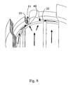
- Figure 8 illustrates the converging flow paths to access point 48 directing air bubbles through second channel 33, through cut out 51 and above the top cap 38 ( Figure 2b ) into the volume between the top cap 38 ( Figure 2b ) and the cover 36 ( Figure 2b ).
- the automatic operation method of this invention can be further improved by incorporation of the following features:
Abstract
Description
- The present invention relates to a liquid filtration device and to a method of removing air bubbles from a fluid passing through such device. faire un Par The IMPACT® LVHD filter, sold by Mykrolis Corporation of Bedford, Massachusetts, has a low hold up volume which is very advantageous due to the high cost of the process fluids principally filtered by the device: photoresist, dielectrics, antireflectives and optical disc materials. The IMPACT LHVD filter provides superior filtration to prevent debris in the process fluid from being deposited onto the substrate and from causing defects.
- A sectional view of the current IMPACT filter may be found in
Figure 1. Figure 1 provides a device that uses three independent connections, avent 12, a feedl4, and anoutlet 16, that can interface with either a stand alone manifold or directly to a dispense system such as the RGEN™ or IntelliGen® dispense systems that are manufactured by Mykrolis Corporation. The process fluid enters through theinlet port 14 and flows through theinlet tube 24 to thehousing bottom 25. The process fluid then flows through thevertical membrane filter 26 to theoutlet port 16, where the purified fluid is directed back to the manifold or dispense system. Thevent port 12 allows bubbles that accumulate on the upstream side of the filter to exit thehousing 22. To better eliminate bubbles from the filter, the top surface of thehousing cap 18 is set at an angle directed up to thevent port 12. This allows air bubbles to gradually rise to the highest point in thehousing 20 and to exit thehousing 22. - A more detailed description of the attributes and benefits of the IMPACT LHVD filter may be found in Mykrolis Applications Note No. MA068 entitled "New Photochemical Filtration Technology for Process Improvement" by M. Clarke and Kwok-Shun Cheng. This paper was originally presented at the INTERFACE `97 Poster Session on November 10, 1997. It is available at http://www.mykrolis.com/micro/appnotesliq.nsf/docs/48LQ63. Also, benefits of the IMPACT LHVD are presented in Mykrolis Applications Note No. MAL109 entitled "Improving Photolithography Equipment OEE with the IMPACT ST Manifold" by M. Clarke. It is available at http://www.mykrolis.com/micro/appnotesliq.nsfrdocs/46AK7B.
- Although the design and performance of the IMPACT LHVD filter is much improved over other filtration devices, it is also not fully optimized for bubble venting. In the IMPACT LHVD filter, bubble-laden fluid is forced to the bottom of the device to sweep the bottom with fluid to prevent fluid stagnation at the bottom and the formation of gel particles. Therefore, any entrained bubbles must then rise to the vent. Again, the slowly rising bubbles from the bottom will require more time and chemical to purge them from the device.
- To compensate for the shortcomings of filters and how they are used in standard filtration and dispense systems, Mykrolis developed integrated filtration and dispense systems called "Two Stage Technology" or "TST". The designs of these TST systems allow for recirculation of bubble-laden fluid to minimize the amount of fluid that is wasted during start-up of a new filter. Although these systems more efficiently remove bubbles from the filter and conserve fluid, waste is still generated, as the venting process is not optimized.
- A more detailed description of the operation of a Two Stage Technology System is given in Mykrolis Applications Note No.
MAL1 11 entitled "Understanding the Operating Cycles of Millipore Two-Stage Technology Photochemical Dispense Systems" by M. Clarke. It is available at http://www.mykrolis.com/micro/appnotesliq.nsf/docs/46FSWG. - For all of these systems (even including TST systems), bubble venting is still not optimized as the venting process release not just bubbles but a bubble saturated fluid stream. Since bubbles do not rise quickly in many process fluids, the motion of the fluid toward the vent is required to remove the bubbles (effectively, the bubbles are carried along by the fluid stream). In addition, the smaller the bubbles to be removed, the more fluid that is ejected in the stream.
- It is apparent from the aforementioned applications notes and discussions that gas bubbles are a concern to semiconductor manufacturers. However, the current IMPACT filter or any other currently available product, inadequately addresses the need to sweep bubbles from all surfaces of the filtration device as well as to initiate bubble removal prior to filtration.
- Accordingly, it would be desirable to provide a liquid filtration device wherein bubble removal from the liquid being filtered be initiated prior to filtration so that the gas bubbles removed are positioned near the vent, thereby facilitating gas bubble removal from the liquid being filtered. Also, it would be desirable to have the system to provide a means for automatic venting of a liquid filtration device that minimizes the amount of fluid loss.
EP-A-0 815 928 discloses a disposable membrane module with low-dead volume. - The present invention provides a device that eliminates gas bubbles from a fluid by using the fluid's velocity within the device, coupled with specific flow channels, to remove pockets of gas from liquid filtration devices. The properly designed flow paths direct fluid into locations where gas bubbles will most likely collect.
- The present invention provides a device as defined in
claim 1 and method as defined in claim 9 for eliminating gas bubbles from a liquid within a housing having a housing cover that will allow for faster and more efficient removal of entrained bubbles. The new device and method uses a portion of the fluid's velocity at the device inlet to sweep around the underside of a flange of a filter cartridge within the device. This will force gas bubbles within the fluid to rise above the filter membrane and adjacent the inside surface of the housing cover. The liquid streams positioned beneath the filter cartridge's flange then converge to the inside surface of the housing cover and proceed to force gas bubbles from the fluid to proceed toward the vent port of the device. - In addition, the present invention provides a method for effecting automatic venting of bubbles from the fluid being filtered.
- It is an aspect of the present invention to provide a liquid filtration device that eliminates gas bubbles from fluid within the device during a vent cycle.
- It is also an aspect of the present invention to provide a liquid filtration device that removes gas bubbles from a fluid by utilizing surfaces in the device while the device is operated in a filtration cycle.
-
-
Figure 1 is a representation of the prior art, a sectional view of an IMPACT LHVD filter. -
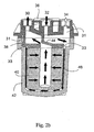
Figures 2a and2b are cross-sectional views of the filtration device of the present invention with arrows representing fluid flow paths. -
Figure 3a is a view of the underside of the top cap of the filtration device of this invention. -
Figure 3b is a partial cross sectional view of the top cap ofFigure 3a positioned relative to a cap on the filter cartridge of this invention. -
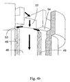
Figure 4a is a partial sectional view of the present invention which shows fluid channels with arrow representing fluid flow paths. -
Figure 4b is an underside view of the device ofFigure 4a . -
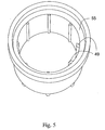
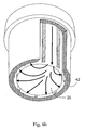
Figure 5 is a top view of the bowl of the filtration device of the present invention. -
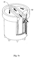
Figure 6a is a partial section view of the present invention which shows fluid channels with arrow representation of the fluid flow path. -
Figure 6b is an underside view of the device ofFigure 6a . -
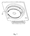
Figure 7 is an underside view of the top cap and housing with arrows representing the fluid flow paths. -
Figure 8 is a partial sectional view of the present invention which shows a fluid channel and arrow representations of fluid flow paths. -
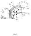
Figure 9 is a partial sectional view of the present invention which shows a fluid channel and the convergence of fluid flow paths access point to force air bubbles above filter cartridge. -
Figure 10 is a bottom view of an alternative housing cover of this invention. -
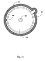
Figure 11 is a bottom view of an alternative top cap of this invention used in conjunction with the housing cover ofFigure 10 . -
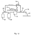
Figure 12 is a flow diagram illustrating an automated method for operating the device of this invention. - The flow direction of both bubbles removed from fluid being filtered and the filtered fluid within the filtration device of this invention depends upon the mode in which the device is being operated. The filtration device of this invention can be operated with the vent either open or closed. In an initial operating mode of the filtration device, the filtration device is filled with fluid and additional fluid is pumped through the device with the vent open to remove the majority of gas and bubbles from the device. During this mode of operation, bubble-laden fluid is also passed through the vent. Subsequent to this initial mode of operation, the vent is closed and the fluid being filtered is pumped through the filter device of this invention. During this mode, bubbles are constantly separated from the fluid being filtered and are collected at or near the vent. In a preferred mode of operation, fluid is recirculated through the filtration device for a period of time to assure complete or substantially complete gas removal from the pores of the filter to minimize the amount of fluid that is wasted. At specific intervals, the vent is opened and bubbles are expelled from the filtration device. The vent then is closed and bubble-free fluid can be dispensed to a point of use. After some period of time, the device will collect additional bubbles and another vent operation is needed. Again, bubbles and fluid will be expelled through the vent.
- The bubbles entrained within the fluid are forced from the fluid along one of two locations within the filtration device. A first channel is positioned in a housing cover of the filtration device and is positioned to be in direct fluid communication with the vent. A second channel is positioned in a top cap above the filter membrane of the filtration device and is positioned to be in direct fluid communication with the first channel. The first channel accumulates bubbles from the fluid as the fluid enters the filtration device. The first channel also is positioned to accept bubbles recovered in the second channel. The second channel accumulates any bubbles that either collect or form on the upstream side of the filtration membrane of the filtration device. Thus, the filtration device recovers bubbles which are immediately released from the fluid upon entering the filtration device and which are released from the fluid prior to filtration.
- The present invention provides a liquid filtration device with internal flow paths that facilitate the removal of air bubbles therefrom, the device comprising a housing, said housing including a bowl; a cap and a cover, the cover having internal and external surfaces and characterized by apertures therein that serve as fluid inlet, outlet and a vent, whereby said cap, cover and bowl are combined in such a manner that fluid channels are created, such channels facilitating sweeping bubbles out of the device and toward the vent, said channels including a fluid channel that directs fluid toward that portion of the housing where the vent is located; a fluid channel that directs fluid to sweep the bottom of the bowl; and a fluid channel that directs fluid to sweep the undersurface of the cap.
- In a preferred embodiment, the device is designed so that the inlet and vent fluid flow path cross-sectional areas are controlled in a manner such that an optimal fluid velocity is achieved for bubble removal and separation, thereby increasing the efficiency of bubble removal.
- In a preferred embodiment, the underside of said top cap has a sloping surface, said sloping surface having a nadir and zenith which is utilized during venting and filtration cycles as well as between cycles. Such a sloping surface will facilitate removal of bubble from the device. Preferably, the surface zenith is juxtaposed to the vent aperture so the bubbles are more efficiently removed from the fluid.
- In a preferred embodiment, vent paths will converge at or near the nadir of the volume between the cap and the cover. It is understood that this volume will be where air bubbles to be purged will congregate. Preferably for this embodiment, the surface zenith is juxtaposed to the vent aperture so the bubbles are more efficiently removed.
- In a preferred embodiment of the present invention, the internal surface of the cover will have a vent ridge, the zenith of said vent ridge positioned substantially near the vent aperture.
- In another preferred embodiment, the vent is located directly above a vent aperture while restricting the vent fluid path to maintain fluid velocity to force gas from the fluid.
- In another preferred embodiment, the vent process is automatically controlled such that minimal fluid is lost during the vent process.
- The present invention provides a method of removing air bubbles from a device intended to filter fluid, said device including an inlet, outlet and vent and said device characterized by being subjected to filtration and vent processes, the method comprising providing fluid channels that are swept during filtration and vent processes. Fluid channels are provided that facilitate the sweeping of air bubbles from the surfaces of the device towards a vent, whereby use of the device in either filtration or venting will remove air bubbles from the device.
- Referring to
Figures 2a and2b , a device of the present invention includes anoutlet 30, aninlet 32 and avent 34 that are formed from thehousing cover 36. Thehousing cover 36 is fitted to thetop cap 38 andhousing bowl 42.Filter media 40 is contained within thehousing bowl 42. The arrows indicate how fluid will flow in the device.Diverter 44 alters the fluid flow path from the inlet towards thevent 34. When the filtration device is filtering fluid, the majority of the fluid will pass directly from theinlet 32 to thehousing bowl 42 while depositing air bubbles in the vicinity of thevent 34. Thehousing cover 36 is provided with afirst channel 31 which extends about the entire or substantially entire circumference ofhousing cover 36 and provides a pathway for gas and bubbles to be directed to vent 34. Thetop cap 38 is provided with asecond channel 33 which extends substantially the entire circumference oftop cap 38 and provides a pathway for gas from inlet fluid to be directed into thefirst channel 31 and then throughvent 34. - Referring to
Figures 3a and3b , thehousing cover 36 has itsinternal surface 37 angled towards thevent side 35 of thehousing cover 36. Thefirst channel 31 spirals up from theoutlet side 39 of thehousing cover 36 to the vent 34 (Figure 2b ) to remove all additional gas bubbles. - Also, as shown in
Figures 3a and3b , inlet fluid is redirected from the center of the housing to the side of the housing by thediverter 44 where the vent 34 (Figure 2b ) is located for this particular design. This configuration forces bubble-laden fluid from the inlet 32 (Figure 2b ) to travel towards the vent 34 (Figure 2b ). By controlling the cross-sectional area, the fluid velocity can be regulated such that buoyant forces and residence time are optimized for efficient bubble removal. The fluid then travels down theside fluid channel 46. -
Figures 4a and4b illustrate the inlet fluid being directed below the top cap 38 (Figure 2b ) through the cut out 52 where it then is split off. Most of the fluid travels down theside fluid channel 46 created with two ribs 49' found on the inside of the bowl 42 (Figure 4b ) to sweep the housing bowl bottom 25 (Figure 6b ) to prevent stagnant fluid locations and the formation of gel particles. The other portion of the inlet fluid entersfluid channels Figure 4b ). By creating a mechanical seal between the top cap 38 (Figure 2b ) and the housing bowl 42 (Figure 2b ), a flow path which allows fluid to travel beneath the top cap 38 (Figure 2b ) and then back above on the opposite side through cut out 51 is generated with twochannels -
Figure 5 illustrates the twolarger ribs 49 positioned a short distance below the topcap seal ridge 55 to direct the inlet fluid to sweep the bottom of bowl 42 (Figure 2b ) and the underside of the top cap 38 (Figure 2b ). -
Figures 6a and6b illustrate the flow of liquid as shown by the arrows. The inlet fluid is directed down theside channel 46 created by ribs 49 (Figure 5 ) and sweeps the volume between the bottom of the filter media 40 (Figure 2b ) and the bottom inner surface ofbowl 42. The fluid is also directed throughchannels 53 and 54 (Figure 4b ) to sweep the underside of thetop cap 38. -
Figure 7 illustrates the fluid flow as it is directed about theunderside 57 of the top cap 38 (Figure 2b ) through second channel 33 (Figure 2b ) on an increasing slope to eliminate gas bubbles. -
Figure 8 illustrates the converging flow paths to accesspoint 48 directing air bubbles throughsecond channel 33, through cut out 51 and above the top cap 38 (Figure 2b ) into the volume between the top cap 38 (Figure 2b ) and the cover 36 (Figure 2b ). -
Figure 9 illustrates the flow path being directed back above thetop cap 38 at the lowest location (nadir) 58 of the volume under the housing cover 36 (Figure 2b ). This ensures that the liquid is forcing the gas bubbles along the underside of the top cap 38 (Figure 2b ) to channel 31 (Figure 2b ). -
Figure 10 illustrates ahousing cover 88 with a restrictedfluid flow path 71 which is provided to prevent reverse fluid flow alongchannel 73. The restrictedflow path 71 allows critical surfaces to be swept during the vent process alone. During the vent process, only a small amount of the fluid entering thefluid inlet 93 is able to pass directly to thevent 92 while the remainder of the fluid velocity is maintained to continue fluid flow below the top cap 81 (Figure 11 ) of the filter cartridge 40 (Figure 2b ) and sweep the underside of thetop cap 81. The fluid then converges to theaccess point 84 of thevent groove 73 where the fluid velocity can be more easily maintained with a small cross-sectional area. In contrast, with unrestricted access to thegas vent 92, the sweeping of the cartridge must be done during the filtration process, thus being less effective than the vent process or both the vent and filtration processes. Thehousing cover 70 is provided withvent 92,fluid inlet 93 andfluid outlet 75. Bothinner surfaces 90 and 77 slope towardgas vent ridge 87 to facilitate gas flow togas vent 92. As shown inFigure 11 , the undersurface 94 oftop cap 81 is provided withgas channel 83 which converges to accesspoint 84 which is in fluid communication with channel 73 (Figure 10 ).Top cap 81 also is provided withoutlet 85 which is in fluid communication with outlet 75 (Figure 10 ). The top cap ofFigure 11 is bonded tohousing cover 88 to blockarea 86 thereby to reduce the hold-up volume and create the fluid flow paths of the filtration apparatus. - The present invention also provides a method for operating the liquid filtration device of this invention in systems for filtering and dispensing process fluids. In a typical application (also called single stage technology), filters are installed dry between a dispense mechanism (e.g. diaphragm pump, air pressurized canister, etc) and an outlet nozzle that directs the fluid onto a substrate such as a semiconductor wafer or optical disc. To remove air from the filter's pores, the process fluid is pushed into the filter and flushed out both the vent and the outlet ports until each fluid stream contains no visible air bubbles. Unfortunately, the fluid sent out the vent and outlet contains many bubbles, and it is well known that bubbles can cause defects on or in a coated substrate. Therefore, this bubble-laden fluid is normally directed to waste and not re-used, and this practice can consume a significant amount of fluid. Process fluids can be expensive ($1,000 to $10,0000 per liter) and minimizing waste by more efficiently eliminating bubbles is important.
- Typical filtration devices are not optimized to remove bubbles. The preferred operation orientation to remove bubbles uses the filter with the fluid inlet at the bottom and the vent at the top. Although this efficiently removes large gas bubbles from the device, smaller bubbles introduced through the inlet rise slowly along the outside of the membrane. Purging these bubbles from the upstream side of the device takes considerable time and wastes fluid. In addition, bubbles can be absorbed by the membrane, resulting in de-wet spots causing shorter filter lifetime and bubble induced substrate defects.
- With a TST system, a microprocessor controls the actions of two pumps with a filter between them to allow for many process benefits. The designs of these systems also allow for recirculation of bubble-laden fluid to minimize the amount of fluid that is wasted during start-up of a new filter. During start-up of a dry filter, fluid is pushed through the filter to the downstream side, where the bubble-laden fluid (from gas removed from the pores of the filter membrane) is cycled back to the inlet of the pump. This fluid is then brought back to the upstream side of the filter. Since the membrane pores are now filled with the process fluid, the membrane is a more effective (but not completely effective) barrier to bubble passage. In the prior art Impact LHVD filter, the bubble laden fluid is directed to the bottom of the filter. Bubbles must then rise by buoyant forces to the filter's vent where they are removed either by an automatic means (software triggered vent valve) or by a manual means (manually actuated vent valve). Although this is a more efficient method for removing bubbles from the filter and conserving fluid, waste is still generated, as the venting process is not optimized. For all of these systems, bubble venting is not optimized as the venting process releases not just bubbles but a bubble saturated fluid stream. Since bubbles do not rise quickly in many process fluids, the motion of the fluid toward the vent is required to remove the bubbles (effectively, the bubbles are carried along by the fluid stream). In addition, the smaller the bubbles to be removed, the more fluid that is ejected in the stream.
- Bubble venting with the liquid filtration device of this invention can use an algorithm to automatically control the venting of filters ("smart venting"). Specifically, smart venting will limit the number of times that the filter undergoes a vent cycle, and it will limit the amount of fluid that is lost during each vent cycle.
- Typically, filters are vented during start-up and during operations as follows:
- (A) In a TST system during filter start-up, the filter is vented every fifth cycle to remove entrapped bubbles. Typically, the vent valve opens for 250 milliseconds, and approximately 50 to 150 microliters of fluid is sent to waste. During a typical start-up and preconditioning process, the filter can be vented more than 200 times. Therefore, this process wastes between approximately 10 milliliters and 30 milliliters of fluid. Also, during normal operation, the filter is vented every cycle, again resulting in between 50 and 150 microliters being lost per each dispense.
- (B) In non-TST applications, venting is usually a manual process and is at the discretion and convenience of the operator. During start-up, venting is more frequent, but the manual aspect of venting results in between 50 to 100 milliliters of fluid loss. Also, since there is typically no recirculation of the filter's downstream fluid, an additional 500 to 1500 milliliters can be wasted conditioning the filter. Finally, during operation, venting can be done once per day, and again, between 20 and 30 milliliters can be lost each time.
- With the liquid filtration device of this invention, smart venting is programmable and automated. On a single stage system, this could be accomplished by using an "intelligent" manifold and the device of this invention. The current IMPACT ST manifold is a passive device, but it can be made to do smart venting by adding a microprocessor and several fluid connections (e.g., solenoid valves, tees). A description of such a system is shown in
Figure 12 . In this figure, the manifold with the filter device of thisinvention 70 controls the operation ofsolenoid vent valve 72 andsolenoid recirculation valve 74. The manifold with the device of this invention is also in communication with apump 89.Tee connection 76 is positioned so that fluid can be directed either throughrecirculation valve 74 or through the stop andsuckback valve 78 to thesubstrate 91.Tee 80 is positioned both to accept fluid fromfluid source 82 during normal operation or fromvalve 74 when the fluid is recirculated to the manifold andfilter device 70. At start-up of a new filter,recirculation valve 74 and stop andsuckback valve 78 are closed and ventvalve 72 is opened. Fluid is then sent into the manifold to fill the housing of the filtration device. After the housing is full, fluid can then be recirculated automatically whilevent valve 72 is closed andrecirculation valve 74 is open so that vent loss can be minimized. At selected times during recirculation (either timed or after a certain number of cycles), therecirculation valve 74 is closed and thevent valve 72 is opened to remove gas from the manifold andfilter 70. After the filter has been primed,valve 74 is closed andvalve 78 is opened so that fluid can be deposited onsubstrate 91. - In most cases, the number of cycles between venting could be lengthened by using the device of this invention. Since bubbles are preferentially trapped and coalesce at the top of the filtration device, they are not in contact with or pass by the filter membrane. As such, they will not form de-wet spots (i.e., causing shorter filter lifetime or introducing bubble induced substrate defects). Therefore, the time between vent processes can be increased.
- Also, the vent valve opening (time and geometry) can be minimized. Currently, the vent valve must be sufficiently open to allow for bubble-laden fluid to flow through the valve. However, since the bubbles will coalesce into larger bubbles, air (with its lower viscosity) flows more easily than fluid through a small passage, and opening the vent ever so slightly for a short time interval would allow air to pass through while not allowing fluid to pass. This could be accomplished by either setting a short vent opening time or controlling the vent valve to minimize its open orifice area. Both would be effective in minimizing the opening of the valve for different viscosity fluids, and both would minimize fluid loss through the vent.
- The automatic operation method of this invention can be further improved by incorporation of the following features:
- (A) Install a membrane contactor type of degasser in the system. This degasser can be installed on the filter's vent line. Also, on a single stage system, it can be upstream of the filter; and on a two stage technology system it is positioned on the upstream side of the pump (but downstream of the line used to recirculate the fluid during start-up). Such a degasser remove bubbles and prevent microbubble formation without affecting the fluid stream. This also has the advantage of practically eliminating venting during normal operation. Other degassing means (e.g., sparging, heating, vacuum, etc.) can be used, but those means usually result in undesirable changes to the process fluid ( e.g., viscosity change due to solvent evaporation).
- (B) Install a bubble detector either in the vent line, in the vent port of the filter itself or in the manifold that connects the filtration device to a two stage technology system. Venting then can be enabled only when the bubble detector senses a sufficient quantity of gas with a signal being read by a microprocessor. In addition, venting can be controlled such that only bubbles are vented and not fluid.
Claims (13)
- A liquid filtration device with internal flow paths that facilitate the purging of air bubbles therefrom, the device comprising:a filter medium (40);a housing including
a bowl (42) defining an opening that receives the filter medium (40) such that a volume is defined between a bottom of the filter medium (40) and a bottom inner surface of the bowl (42);
a cap (38) substantially covering the opening of the bowl (42) in which the filter medium (40) is received; and
a cover (36) fitted to the cap (38) and the bowl (42) so as to close the bowl (42), the cover (36) having internal and external surfaces and apertures therein that serve as fluid inlet (32), outlet (30) and vent (34) of the filtration device, and the cap (38) including a first cut-out (52) for allowing fluid from the inlet (32) to enter the bowl (42) and a second cut-out (51) for allowing fluid from the bowl (42) to enter a volume between the cap (38) and the cover (36);
whereby said cap (38), cover (36) and bowl (42) are combined in such a manner that fluid channels are created which facilitate sweeping gas and bubbles out of the device and toward the vent (34) which are immediately released from the fluid upon entering the filtration device and which are released from the fluid prior to filtration, said channels including
a first fluid channel (31) defined in the volume between the cover (36) and the cap (38) and communicating with the inlet (32), for directing gas and bubbles toward the vent (34);
a second fluid channel (33,53,54) defined on an underside of the cap (38), for directing a portion of the fluid that has been directed below the cap (38) through the first cut-out (52) to sweep the underside of the cap (38), the second fluid channel (33,53,54) being coupled with the first fluid channel (31) by the second cut-out (51) defined in the cap (38);
a third fluid channel (46) defined between the bowl (42) and the filter medium (40) for directing another portion of the fluid that has been directed below the cap (38) through the first cut-out (52) toward the volume defined between the bottom of the filter medium (40) and the bottom inner surface of the bowl (42) to sweep the volume; and
a plurality of fourth fluid channels provided for directing the fluid from the volume defined between the bottom of the filter medium (40) and the bottom inner surface of the bowl (42) toward the second fluid channel (33,53,54). - The device of claim 1 wherein the second fluid channel (33,53,54) comprises two channels (53,54) that converge at the second cut-out (51) defined in the cap (38).
- The device of claim 2, whereby the underside of said cap (38) has a sloping surface.
- The device of claim 2 or 3, wherein said second cut-out (51) defined in the cap (38) is juxtaposed to a nadir (58) of the volume between the cap (38) and the cover (36).
- The device of any one of claims 1 to 4, wherein the first fluid channel (31) comprises a channel which extends substantially the entire circumference of the cover (36).
- The device of any one of claims 1 to 5, wherein the second fluid channel (33,53,54) extends substantially about the circumference of the cap (38).
- The device of any one of claims 1 to 6, wherein the first fluid channel (31) extends substantially about the circumference of the cover (36) such that the first fluid channel (31) spirals up from an outlet side (39) of the cover (36) to provide a pathway for the gas and bubbles to be directed to the vent (34).
- The device of any one of claims 1 to 7, wherein at least one flow channel is defined in the volume between the bottom of the bowl (42) and the bottom of the filter medium (40) for allowing sweeping the bottom of the bowl (42).
- A method of removing air bubbles from a fluid passing through a filter device as defined in any one of claims 1 to 8, comprising:directing the fluid from the inlet (32) toward the vent (34) through the first fluid channel (31), the first fluid channel (31) accumulating bubbles near the vent (34) from the fluid as the fluid enters the filter device.
- The method of claim 9, further comprising
directing the fluid from the first fluid channel (31) to sweep the underside of the cap (38) through the second fluid channel (33,53,54), the second fluid channel (33,53,54) accumulating bubbles from the fluid that collect or form near the undersurface of the cap (38); and
further directing the fluid from the second fluid channel (33,53,54) back to the first fluid channel (31) through the second cut-out (51) defined in the cap (38), the first fluid channel (31) accumulating bubbles recovered in the second fluid channel (33,53,54) near the vent (34). - The method of claim 9 or 10, further comprising opening the vent (34) to enable the bubbles that accumulate near the vent (34) to be expelled.
- The method of claim 11, further comprising opening and closing the vent (34) for time intervals that minimize fluid loss.
- The method of claim 9, 10, 11 or 12, further comprising providing a degassing membrane contactor external to and in fluid communication with the filter device to further eliminate bubbles.
Applications Claiming Priority (3)
| Application Number | Priority Date | Filing Date | Title |
|---|---|---|---|
| US23220900P | 2000-09-13 | 2000-09-13 | |
| US232209P | 2000-09-13 | ||
| PCT/US2001/028771 WO2002022232A1 (en) | 2000-09-13 | 2001-09-13 | Liquid filtration device |
Publications (2)
| Publication Number | Publication Date |
|---|---|
| EP1322395A1 EP1322395A1 (en) | 2003-07-02 |
| EP1322395B1 true EP1322395B1 (en) | 2011-02-23 |
Family
ID=22872266
Family Applications (1)
| Application Number | Title | Priority Date | Filing Date |
|---|---|---|---|
| EP01968877A Expired - Lifetime EP1322395B1 (en) | 2000-09-13 | 2001-09-13 | Liquid filtration device |
Country Status (8)
| Country | Link |
|---|---|
| US (5) | US6846409B2 (en) |
| EP (1) | EP1322395B1 (en) |
| JP (1) | JP2004508183A (en) |
| KR (1) | KR100582967B1 (en) |
| CN (1) | CN1183993C (en) |
| DE (1) | DE60144097D1 (en) |
| TW (1) | TW508260B (en) |
| WO (1) | WO2002022232A1 (en) |
Families Citing this family (47)
| Publication number | Priority date | Publication date | Assignee | Title |
|---|---|---|---|---|
| US6378907B1 (en) | 1996-07-12 | 2002-04-30 | Mykrolis Corporation | Connector apparatus and system including connector apparatus |
| WO2001095995A2 (en) * | 2000-05-12 | 2001-12-20 | Pall Corporation | Filters |
| KR100582967B1 (en) | 2000-09-13 | 2006-05-24 | 엔테그리스, 아이엔씨. | Liquid filtration device |
| US20030019819A1 (en) * | 2001-07-30 | 2003-01-30 | Karl Fritze | Hot disconnect replaceable water filter assembly |
| TWI245163B (en) | 2003-08-29 | 2005-12-11 | Asml Netherlands Bv | Lithographic apparatus and device manufacturing method |
| US20090001019A1 (en) * | 2004-06-03 | 2009-01-01 | Mykrolis Corporation | Fluid Treating Apparatus |
| US7393388B2 (en) * | 2005-05-13 | 2008-07-01 | United Technologies Corporation | Spiral wound fuel stabilization unit for fuel de-oxygenation |
| US7435283B2 (en) * | 2005-05-18 | 2008-10-14 | United Technologies Corporation | Modular fuel stabilization system |
| US7465336B2 (en) * | 2005-06-09 | 2008-12-16 | United Technologies Corporation | Fuel deoxygenation system with non-planar plate members |
| US7377112B2 (en) | 2005-06-22 | 2008-05-27 | United Technologies Corporation | Fuel deoxygenation for improved combustion performance |
| WO2007010037A1 (en) * | 2005-07-22 | 2007-01-25 | Mann+Hummel Gmbh | Fuel filter |
| US20070101731A1 (en) * | 2005-09-07 | 2007-05-10 | United Technologies Corporation | Deoxygenated fuel-cooled environmental control system pre-cooler for an aircraft |
| US9258259B2 (en) * | 2005-09-30 | 2016-02-09 | Nokia Technologies Oy | Retrieval of offline instant messages |
| US7615104B2 (en) | 2005-11-03 | 2009-11-10 | United Technologies Corporation | Fuel deoxygenation system with multi-layer oxygen permeable membrane |
| US20070130956A1 (en) * | 2005-12-08 | 2007-06-14 | Chen Alexander G | Rich catalytic clean burn for liquid fuel with fuel stabilization unit |
| US7824470B2 (en) * | 2006-01-18 | 2010-11-02 | United Technologies Corporation | Method for enhancing mass transport in fuel deoxygenation systems |
| US7582137B2 (en) * | 2006-01-18 | 2009-09-01 | United Technologies Corporation | Fuel deoxygenator with non-planar fuel channel and oxygen permeable membrane |
| US7569099B2 (en) * | 2006-01-18 | 2009-08-04 | United Technologies Corporation | Fuel deoxygenation system with non-metallic fuel plate assembly |
| JP5354525B2 (en) * | 2006-08-25 | 2013-11-27 | インテグリス・インコーポレーテッド | Air ventable filter device |
| PE20091163A1 (en) | 2007-11-01 | 2009-08-09 | Wyeth Corp | ANTIBODIES FOR GDF8 |
| EP2221094A4 (en) * | 2007-11-29 | 2011-05-04 | Entegris Inc | Filter unit and filter cartridge |
| KR100921743B1 (en) * | 2007-12-14 | 2009-10-15 | 한국생산기술연구원 | Filtering Apparatus of Vacuum Pump |
| US9463399B2 (en) | 2009-11-12 | 2016-10-11 | Donaldson Company, Inc. | Liquid filter construction for freezing environments |
| EP2678088B1 (en) * | 2011-02-24 | 2020-06-03 | Saint-Gobain Performance Plastics Corporation | Modular filter capsule apparatus |
| US9682335B2 (en) | 2011-02-24 | 2017-06-20 | Saint-Gobain Performance Plastics Corporation | Modular filter capsule apparatus |
| JP6195436B2 (en) * | 2012-10-29 | 2017-09-13 | スリーエム イノベイティブ プロパティズ カンパニー | FILTER DEVICE, FILTER DEVICE ASSEMBLY METHOD, FILTER METHOD USING FILTER DEVICE, FILTER PRODUCTION METHOD USING FILTER DEVICE |
| US9421498B2 (en) * | 2012-11-12 | 2016-08-23 | Pall Corporation | Systems and methods for conditioning a filter assembly |
| US9656197B2 (en) * | 2012-11-12 | 2017-05-23 | Pall Corporation | Systems and methods for conditioning a filter assembly |
| US9731231B2 (en) | 2013-03-07 | 2017-08-15 | Taiwan Semiconductor Manufacturing Company, Ltd. | Laminar flow intake channeling device |
| US9719504B2 (en) * | 2013-03-15 | 2017-08-01 | Integrated Designs, L.P. | Pump having an automated gas removal and fluid recovery system and method |
| JP2015106656A (en) * | 2013-11-29 | 2015-06-08 | 東京エレクトロン株式会社 | Filter device |
| US11351509B2 (en) * | 2013-12-06 | 2022-06-07 | Taiwan Semiconductor Manufacturing Company, Ltd. | Filter with seal treatment |
| JP2014195807A (en) * | 2014-06-18 | 2014-10-16 | 株式会社ロキテクノ | Filter module attaching/detaching device and filtration unit |
| WO2016100510A1 (en) * | 2014-12-16 | 2016-06-23 | Saint-Gobain Performance Plastics Corporation | Modular filter capsule apparatus |
| US10121685B2 (en) * | 2015-03-31 | 2018-11-06 | Tokyo Electron Limited | Treatment solution supply method, non-transitory computer-readable storage medium, and treatment solution supply apparatus |
| US10729991B2 (en) | 2015-06-22 | 2020-08-04 | 3M Innovative Properties Company | Compact cross-flow contactor |
| GB201516863D0 (en) * | 2015-09-23 | 2015-11-04 | Castrol Ltd | Fluid method and system |
| CN105781828A (en) * | 2015-11-24 | 2016-07-20 | 黄梅福德银汽配有限公司 | Novel automatic exhaust diesel oil filter seat |
| WO2017112455A2 (en) | 2015-12-22 | 2017-06-29 | Corning Incorporated | Cell separation device and method for using same |
| WO2018013071A1 (en) | 2016-07-11 | 2018-01-18 | Hewlett-Packard Development Company, L.P. | Froth coalescing |
| US11213775B2 (en) | 2017-09-25 | 2022-01-04 | Cummins Filtration Ip, Inc. | Fuel filter cartridges with automated air-bleeding internal features |
| CA3108180A1 (en) | 2018-07-30 | 2020-02-06 | Shaw Development, Llc | Aqueous fluid filter assembly with aeration mitigation |
| CN110052060B (en) * | 2019-04-24 | 2022-07-01 | 杭州科百特过滤器材有限公司 | Hollow fiber degassing membrane module |
| CN114555211A (en) * | 2019-06-25 | 2022-05-27 | 唐纳森公司 | Filter element end cap with shield |
| US11241644B2 (en) | 2020-04-13 | 2022-02-08 | Pall Corporation | Adapter for filter device and method of use |
| CN113413672B (en) * | 2021-06-28 | 2023-02-28 | 张春燕 | Filter |
| US20230134445A1 (en) * | 2021-11-04 | 2023-05-04 | Entegris, Inc. | Filter cartridge assembly |
Family Cites Families (177)
| Publication number | Priority date | Publication date | Assignee | Title |
|---|---|---|---|---|
| US468390A (en) * | 1892-02-09 | Low-water alarm | ||
| US136631A (en) * | 1873-03-11 | Improvement in steam-power-brake couplings | ||
| US423081A (en) * | 1890-03-11 | Cable-railway crossing | ||
| US420209A (en) * | 1890-01-28 | Pipe-coupling for railway-cars | ||
| US898214A (en) | 1903-11-27 | 1908-09-08 | Edward E Gold | Automatic pipe-coupling for railway-cars. |
| US872174A (en) * | 1907-03-25 | 1907-11-26 | Ralph M Fyock | Automatic train-pipe coupling. |
| US891718A (en) * | 1907-06-21 | 1908-06-23 | Thomas B Mcmillan | Coupling. |
| US872707A (en) * | 1907-06-29 | 1907-12-03 | Peter Beahm | Automatic connector for train-pipes. |
| US940334A (en) * | 1909-01-11 | 1909-11-16 | William D Leftwich | Coupling mechanism. |
| US967516A (en) | 1909-09-01 | 1910-08-16 | Henry Cain J | Automatic air-coupling. |
| US1070110A (en) | 1912-04-27 | 1913-08-12 | James A Tate | Automatic air-brake coupling or connector. |
| US1186068A (en) * | 1915-10-30 | 1916-06-06 | Warren C Benjamin | Air-brake coupling. |
| US1221682A (en) * | 1916-04-20 | 1917-04-03 | William C Coffield | Air-coupling. |
| US1389012A (en) * | 1920-07-10 | 1921-08-30 | John W Roberts | Pipe-coupling for railway rolling-stock |
| DE423081C (en) * | 1923-05-02 | 1925-12-18 | Hoechst Ag | Process for the preparation of sulfoalkyl and sulfoaryl ethers from resinous condensation products derived from phenols |
| US1786066A (en) * | 1928-09-12 | 1930-12-23 | Cobb Connector Company | Train-pipe coupler |
| BE344502A (en) * | 1929-12-05 | |||
| US1886398A (en) * | 1931-08-13 | 1932-11-08 | Arthur C Harrell | Automatic train pipe coupling |
| US2462488A (en) * | 1945-06-07 | 1949-02-22 | Fram Corp | Control plate for filter cartridges |
| US2997180A (en) * | 1957-06-03 | 1961-08-22 | Chrysler Corp | Anti-vapor-lock fuel filter |
| US3107601A (en) | 1958-09-02 | 1963-10-22 | Richard L Longmire | Filtration and recirculation system for deep fat cooking apparatus |
| US3052863A (en) | 1961-03-16 | 1962-09-04 | Ibm | Contact connector operating devices |
| US3214195A (en) | 1962-05-25 | 1965-10-26 | Crawford Fitting Co | Coupling device for interconnecting multiple fluid lines |
| US3399776A (en) | 1965-09-02 | 1968-09-03 | Robert R. Knuth | Detachable snap-on filter for a hydraulic system |
| DE1525925A1 (en) | 1966-09-16 | 1970-01-22 | Vickers Zimmer Ag | Flange connection, especially for double pipelines |
| US3469863A (en) | 1967-04-05 | 1969-09-30 | Trico Products Corp | Fluid coupling assembly |
| US3493115A (en) * | 1968-01-29 | 1970-02-03 | Ultra Tech Corp | Cam lock cartridge system |
| US3519133A (en) * | 1968-07-09 | 1970-07-07 | Dover Corp | Fluid filter means |
| US3560377A (en) * | 1969-01-21 | 1971-02-02 | Amicon Corp | Apparatus and process for filtering fluids |
| US3706184A (en) | 1969-06-09 | 1972-12-19 | Matter Mfg Corp | Wall-recessed suction cleaner |
| US3734851A (en) * | 1969-12-29 | 1973-05-22 | K Matsumura | Method and device for purifying blood |
| US3628662A (en) | 1970-03-26 | 1971-12-21 | Marvel Eng Co | Filter antidrain valve assembly |
| US3650251A (en) * | 1970-05-11 | 1972-03-21 | Mack Trucks | Hydraulic valve lifter |
| US3695446A (en) | 1970-10-15 | 1972-10-03 | Culligan Int Co | Membrane module assembly |
| US3947080A (en) * | 1971-06-14 | 1976-03-30 | Underwriters Safety Device Co. | Quick-connect-disconnect terminal block assembly |
| US3880757A (en) * | 1971-09-08 | 1975-04-29 | Gary Thomason | Filtering system |
| BE791684A (en) * | 1971-11-22 | 1973-03-16 | Ogden Hubert S | REMOVABLE FILTER CARTRIDGE |
| US3802564A (en) * | 1972-06-09 | 1974-04-09 | W Turman | Oil filter and adapter |
| US3812659A (en) * | 1972-08-02 | 1974-05-28 | Whirlpool Co | Canister vacuum cleaner latching means |
| US3935106A (en) * | 1974-01-23 | 1976-01-27 | Lipner Herbert D | Water filter assembly |
| US3950251A (en) * | 1974-03-25 | 1976-04-13 | Rayne International | Filter with quick-connect coupling |
| GB1496035A (en) * | 1974-07-18 | 1977-12-21 | Iwaki Co Ltd | Magnetically driven centrifugal pump |
| JPS51111902A (en) | 1975-03-26 | 1976-10-02 | Iwaki:Kk | Magnet pump |
| US4089549A (en) * | 1976-10-21 | 1978-05-16 | Stratoflex, Inc. | Simultaneous plural fluid conductor connections |
| US4151823A (en) * | 1977-07-28 | 1979-05-01 | Grosse Leland J | Quick-change oil filter/reservoir system for internal combustion engine |
| US4174231A (en) * | 1977-09-08 | 1979-11-13 | Hobgood Harold G | Method for flushing the crankcase of an internal combustion engine |
| NO140919C (en) * | 1978-04-17 | 1979-12-12 | Helge Dybvig | FUEL SYSTEM DEVICE, ESPECIALLY FOR BOATS |
| US4187179A (en) * | 1978-08-14 | 1980-02-05 | Harms John F | Electrically grounded filter plate |
| US4298358A (en) * | 1979-01-11 | 1981-11-03 | Baxter Travenol Laboratories, Inc. | Gas separating and venting filter |
| DE3005408A1 (en) * | 1979-02-15 | 1980-08-21 | Daicel Chem | SEMIPERMEABLES MEMBRANE ELEMENT |
| US4283284A (en) | 1979-07-18 | 1981-08-11 | Baxter Travenol Laboratories, Inc. | Hollow fiber dialyzer end seal system |
| US4321911A (en) * | 1979-08-15 | 1982-03-30 | Offutt Worthington W | Modular solar collector system |
| US4344777A (en) * | 1980-01-07 | 1982-08-17 | Siposs George G | Directed flow bubble trap for arterial blood |
| US4629563B1 (en) | 1980-03-14 | 1997-06-03 | Memtec North America | Asymmetric membranes |
| US4629475A (en) * | 1980-05-13 | 1986-12-16 | Polaroid Corporation | Liquid debubbling apparatus and method |
| US4414109A (en) | 1980-09-29 | 1983-11-08 | Purex Corporation | Multi-ported valve with sealing network between valve body and rotor |
| US4529512A (en) * | 1981-01-19 | 1985-07-16 | Clark Equipment Company | Hydraulic reservoir |
| DE3271301D1 (en) * | 1981-02-23 | 1986-07-03 | Nippon Denso Co | Fluid cleaner systems |
| US4404103A (en) | 1981-11-05 | 1983-09-13 | Drath Edwin H | Rocking swivel hose connectors and method |
| US4416775A (en) | 1981-12-14 | 1983-11-22 | Std Filter Company, Inc. | In-line filter and cartridge therefor |
| USRE32711E (en) * | 1981-12-23 | 1988-07-12 | Shiley, Inc. | Arterial blood filter with improved gas venting |
| US4411783A (en) * | 1981-12-23 | 1983-10-25 | Shiley Incorporated | Arterial blood filter with improved gas venting |
| US4524807A (en) * | 1982-05-21 | 1985-06-25 | Humphrey Products Company | Snap-together modular manifold construction |
| US4494775A (en) * | 1982-09-30 | 1985-01-22 | William Nash Company, Inc. | Fluid coupling |
| US4555130A (en) | 1983-04-01 | 1985-11-26 | The United States Of America As Represented By The Secretary Of The Navy | Diver's umbilical quick-disconnect device |
| NL8301870A (en) * | 1983-05-26 | 1984-12-17 | Wavin Bv | SEAL FOR AN APPARATUS FOR PURIFYING LIQUIDS BY MEMBRANE FILTRATION. |
| US4535997A (en) * | 1983-06-24 | 1985-08-20 | Brust John E | Sealing system |
| US4522717A (en) * | 1983-06-24 | 1985-06-11 | Brust John E | Filter apparatus |
| DE3327431A1 (en) | 1983-07-29 | 1985-02-14 | Wilhelm 2000 Hamburg Heine | DEVICE FOR FILTERING AND SEPARATING FLOW MEDIA, ESPECIALLY FOR WATER DESALINATION AND WATER PURIFICATION BY REVERSE OSMOSIS AND ULTRAFILTRATION |
| EP0138060B1 (en) * | 1983-09-16 | 1990-03-07 | Mitsubishi Rayon Co., Ltd. | Hollow-fiber filtering module and water purification device utilizing it |
| US4629568A (en) | 1983-09-26 | 1986-12-16 | Kinetico, Inc. | Fluid treatment system |
| US4610781A (en) | 1983-12-30 | 1986-09-09 | Baxter Travenol Laboratories, Inc. | Fluid processing system with flow control manifold |
| JPS60179189A (en) * | 1984-02-27 | 1985-09-13 | Hitachi Ltd | Water purifier |
| US4879032A (en) | 1984-06-04 | 1989-11-07 | Allied Resin Corporation | Fluid separatory devices having improved potting and adhesive compositions |
| US4645601A (en) * | 1984-08-31 | 1987-02-24 | Everpure, Inc. | Quick change reverse osmosis assembly |
| US4559136A (en) | 1984-08-31 | 1985-12-17 | Vortex Innerspace Products, Inc. | Aquarium filtering system |
| DE3519060A1 (en) | 1985-05-28 | 1986-12-04 | Robert Dipl.-Ing. Dr. 3352 Einbeck Kohlheb | SEPARATING CELL FOR PRESSURE FILTRATION AND REVERSE OSMOSIS |
| US4654142A (en) * | 1985-11-18 | 1987-03-31 | Everpure, Inc. | Filtering system |
| US4735716A (en) * | 1986-01-27 | 1988-04-05 | Cuno Corporated | Quick-change filter cartridge and head therefor |
| US4719012A (en) * | 1986-05-30 | 1988-01-12 | Caterpillar Inc. | Twist on disposable filter |
| US4820174A (en) * | 1986-08-06 | 1989-04-11 | Amp Incorporated | Modular connector assembly and filtered insert therefor |
| US4664420A (en) * | 1986-09-02 | 1987-05-12 | Island Rubber & Equipment Co., Inc. | Pneumatic self-sealing female coupling incorporating combination locking tumblers |
| US4870961A (en) * | 1986-09-22 | 1989-10-03 | Barnard Gordon D | Medical ventilator tube and manifold assembly |
| US4708157A (en) * | 1986-10-07 | 1987-11-24 | Flowtron Industries, Inc. | Air eliminator for fluid handling systems |
| US4759571A (en) * | 1986-10-31 | 1988-07-26 | D. W. Zimmerman Mfg., Inc. | Fluid transfer module with multiple flow paths |
| JPH0520404Y2 (en) * | 1986-11-04 | 1993-05-27 | ||
| US4900449A (en) * | 1987-05-20 | 1990-02-13 | Gelman Sciences | Filtration membranes and method of making the same |
| US4806240A (en) * | 1987-06-12 | 1989-02-21 | Cuno, Incorporated | Adapter and cartridge assembly |
| US4846800A (en) * | 1987-10-14 | 1989-07-11 | Kenneth Ouriel | Two chambered autotransfuser device and method of use |
| US4904382A (en) * | 1987-11-23 | 1990-02-27 | Everpure, Inc. | Filter cartridge security for locking between operating and non-operating positions |
| DE3740418A1 (en) | 1987-11-28 | 1989-06-08 | Joachim Wolf | FILTER DEVICE |
| US4966699A (en) | 1988-05-25 | 1990-10-30 | Terumo Kabushiki Kaisha | Hollow fiber membrane fluid processor |
| US5057131A (en) | 1988-09-26 | 1991-10-15 | The Scott Fetzer Company | Vacuum cleaner filter bag assembly |
| US4857189A (en) | 1988-10-13 | 1989-08-15 | Everpure, Inc. | Filter cartridge with a lugged concentric closure portion |
| US4900065A (en) * | 1988-10-31 | 1990-02-13 | Dlh Industries, Inc. | Quick-connect fluid coupling |
| US5167837A (en) * | 1989-03-28 | 1992-12-01 | Fas-Technologies, Inc. | Filtering and dispensing system with independently activated pumps in series |
| NL8901090A (en) | 1989-04-28 | 1990-11-16 | X Flow Bv | METHOD FOR MANUFACTURING A MICROPOROUS MEMBRANE AND SUCH MEMBRANE |
| US5149260A (en) * | 1989-05-01 | 1992-09-22 | Foust Harry D | Device and method for combustion of waste oil |
| US4932987A (en) * | 1989-05-25 | 1990-06-12 | Jorge Molina | Extra corporeal air eliminator |
| US4964984A (en) | 1989-06-14 | 1990-10-23 | Electromedics, Inc. | Blood filter |
| JPH0347271A (en) * | 1989-07-14 | 1991-02-28 | Terumo Corp | Liquid treatment device |
| DK162191C (en) * | 1989-09-15 | 1992-02-17 | Eskofot As | FILTER FOR FILTER FILTERING |
| US4944776A (en) | 1989-10-05 | 1990-07-31 | Andrew Corporation | Dehumidifier for waveguide system |
| US5221473A (en) * | 1989-10-13 | 1993-06-22 | Burrows Bruce D | Filter cartridge assembly for a reverse osmosis purification system |
| YU212089A (en) * | 1989-11-06 | 1992-05-28 | Lazarevic Bogdan | Pipeline for gas under high pressure |
| US5041220A (en) | 1990-01-09 | 1991-08-20 | Minntech Corporation | Hollow fiber filter cartridge for a standarized housing |
| US5022986A (en) * | 1990-01-11 | 1991-06-11 | John Lang | Manifold and disposable filter assembly |
| US5108598A (en) * | 1990-02-14 | 1992-04-28 | Ultra Flow, Inc. | Horizontal motion quick-disconnect filter system with recirculating bypass |
| US5069780A (en) | 1990-06-04 | 1991-12-03 | Infinitex | Ultrafiltration device and process |
| US5362406A (en) * | 1990-07-27 | 1994-11-08 | Pall Corporation | Leucocyte depleting filter device and method of use |
| US5066391A (en) | 1990-08-22 | 1991-11-19 | Faria Manuel S | Reusable liquid filter assembly |
| US5176828A (en) | 1991-02-04 | 1993-01-05 | Millipore Corporation | Manifold segment stack with intermediate feed manifold |
| US5096230A (en) * | 1991-03-20 | 1992-03-17 | General Resource Corporation | Quick release adapter for connecting an exhaust removal hose to a vehicle tail pipe using magnets |
| US5262068A (en) * | 1991-05-17 | 1993-11-16 | Millipore Corporation | Integrated system for filtering and dispensing fluid having fill, dispense and bubble purge strokes |
| DE4222193C2 (en) * | 1991-07-09 | 1994-08-11 | Faster Srl | Quick coupling for simultaneously establishing or releasing the connections of several couplings and / or connecting plugs, in particular coupling block for front loader on vehicles |
| WO1993014858A1 (en) * | 1992-01-22 | 1993-08-05 | Allied-Signal Inc. | Quick connect/disconnect liquid filter |
| US5180490A (en) * | 1992-01-31 | 1993-01-19 | Baldwin Filters, Inc. | Lubricant filter assembly with internal bypass lock-out |
| JP3373597B2 (en) * | 1992-06-18 | 2003-02-04 | スタナダイン・オートモーティヴ・コーポレイション | Fuel filter with internal vent |
| US5178758A (en) * | 1992-06-30 | 1993-01-12 | Hwang Ching F | Biochemical water filter |
| DE4228155C1 (en) * | 1992-08-25 | 1993-12-02 | Daimler Benz Ag | Device for fastening at least one exposed line to a fastening body, in particular a fuel filter for an internal combustion engine |
| US5399263A (en) * | 1992-09-24 | 1995-03-21 | Barnstead Thermolyne | Water purifier |
| US5324483B1 (en) * | 1992-10-08 | 1996-09-24 | Warner Lambert Co | Apparatus for multiple simultaneous synthesis |
| US5320752A (en) * | 1992-11-03 | 1994-06-14 | Clack Corporation | Water purification system employing modular flat filter assembly |
| US5401401A (en) * | 1993-01-13 | 1995-03-28 | Aquaria Inc. | Hang on tank canister filter |
| US5449454A (en) * | 1993-01-13 | 1995-09-12 | Aquaria, Inc. | Gas expelling device for a canister type filter |
| US5336406A (en) * | 1993-01-26 | 1994-08-09 | Elkay Manufacturing Company | Replaceable filter cartridge and head assembly with safety shut-off valve |
| US5380437A (en) * | 1993-02-02 | 1995-01-10 | Biomedical Research And Development Laboratories, Inc. | Multifunctional filtration apparatus |
| US5389260A (en) * | 1993-04-02 | 1995-02-14 | Clack Corporation | Brine seal for tubular filter |
| DE4321927C2 (en) * | 1993-07-01 | 1998-07-09 | Sartorius Gmbh | Filter unit with degassing device |
| US5397462A (en) * | 1993-08-24 | 1995-03-14 | Matsushita Electric Industrial Co., Ltd. | Filter with laterally removable element and valve means |
| DE4340218C1 (en) * | 1993-11-25 | 1994-09-22 | Enderle Guenther Dipl Ing Fh | Filter apparatus |
| US5484527A (en) * | 1993-12-13 | 1996-01-16 | Stanadyne Automotive Corp. | Module for filter assembly base |
| US5387339A (en) * | 1993-12-17 | 1995-02-07 | Coors Brewing Company | High efficiency liquid filtration system and method for using the same |
| US5417459A (en) * | 1994-02-24 | 1995-05-23 | Sonsub, Inc. | Subsea umbilical connector |
| US5632894A (en) * | 1994-06-24 | 1997-05-27 | Gish Biomedical, Inc. | Arterial blood filter with upwardly inclining delivery inlet conduit |
| US5601710A (en) * | 1994-07-08 | 1997-02-11 | Samsung Electronics Co., Ltd. | Filtering apparatus of water purifier |
| US5462675A (en) * | 1994-07-15 | 1995-10-31 | Pall Corporation | Filter assembly and method of reducing hold-up in a filter assembly |
| US5902551A (en) * | 1995-01-13 | 1999-05-11 | Semi-Gas Systems, Inc. | Process gas docking station with point-of-use filter for receiving removable purifier cartridges |
| US5549010A (en) * | 1995-01-13 | 1996-08-27 | Ziba Design, Inc. | Readily serviceable ancillary fluid filtration system having visual flow rate indicator and quick-release fluid hose fitting |
| US5651765A (en) * | 1995-04-27 | 1997-07-29 | Avecor Cardiovascular Inc. | Blood filter with concentric pleats and method of use |
| US5507530A (en) * | 1995-05-08 | 1996-04-16 | Soo Tractor Sweeprake Company | Plural male and female fluid coupler connecting mechanism and method |
| US5685894A (en) * | 1995-09-13 | 1997-11-11 | Electrolux Corporation | Filter and accessory mount for upright vacuum cleaner exhaust port |
| DE69623133T2 (en) * | 1995-09-14 | 2002-12-12 | Pall Corp | METHOD AND DEVICE FOR REMOVING IRON FROM AQUEOUS LIQUIDS |
| US6059318A (en) * | 1996-04-30 | 2000-05-09 | E. I. Du Pont De Nemours And Company | Lateral entry remotely operated coupling system |
| US5925025A (en) * | 1996-06-05 | 1999-07-20 | Tyco Group S.A.R.L. | Filtration valve cap with reflux clearing feature and related method of use thereof |
| US5762789A (en) * | 1996-06-28 | 1998-06-09 | Millipore Corporation | Disposable membrane module with low-dead volume |
| US6378907B1 (en) * | 1996-07-12 | 2002-04-30 | Mykrolis Corporation | Connector apparatus and system including connector apparatus |
| US6068770A (en) * | 1996-07-12 | 2000-05-30 | Millipore Corporation | Disposable separation module with quick connect capability |
| JPH1043293A (en) * | 1996-08-08 | 1998-02-17 | Senko Ika Kogyo Kk | Device for removing bubble in liquid |
| US5858224A (en) * | 1997-03-18 | 1999-01-12 | Nelson Industries, Inc. | Filter with pressure sensor mounted in housing end |
| US6048454A (en) * | 1997-03-18 | 2000-04-11 | Jenkins; Dan | Oil filter pack and assembly |
| US5902511A (en) * | 1997-08-07 | 1999-05-11 | North American Refractories Co. | Refractory composition for the prevention of alumina clogging |
| US6159366A (en) * | 1997-08-21 | 2000-12-12 | Carroll; Randall Scott | No spill, self-bleeding filter |
| US5911879A (en) * | 1997-09-24 | 1999-06-15 | Eaton Corporation | Refrigerant filter/drier |
| US6024229A (en) * | 1998-02-27 | 2000-02-15 | Ayers; William R. | Reusable filter assembly |
| US6523861B1 (en) * | 1998-05-26 | 2003-02-25 | Gary Clancy | Fluid coupling and method of use |
| US6059797A (en) * | 1998-06-17 | 2000-05-09 | Ensurg, Inc. | Self-disposing ligating band dispenser |
| USD423081S (en) | 1998-07-10 | 2000-04-18 | Millipore Corporation | Connector |
| EP1119403B1 (en) * | 1998-10-09 | 2008-07-09 | Entegris, Inc. | Filter cartridge and bowl with snap-fit connection |
| JP2000140524A (en) * | 1998-11-05 | 2000-05-23 | Nippon Rokaki Kk | Filter apparatus |
| US7029238B1 (en) * | 1998-11-23 | 2006-04-18 | Mykrolis Corporation | Pump controller for precision pumping apparatus |
| FR2788561B1 (en) * | 1999-01-14 | 2001-02-16 | Snecma | FUEL SYSTEM WITH PROTECTED MAIN FILTER |
| US6139738A (en) * | 1999-03-10 | 2000-10-31 | Parker-Hannifin Corporation | Cartridge filter with integrated threading having anti-rotation feature |
| US6302147B1 (en) * | 1999-04-08 | 2001-10-16 | Joseph Lorney Rose | Automatic dry release valve coupling |
| US6176904B1 (en) | 1999-07-02 | 2001-01-23 | Brij M. Gupta | Blood filter |
| ATE452692T1 (en) | 2000-05-12 | 2010-01-15 | Pall Corp | FILTRATION SYSTEMS |
| WO2001095995A2 (en) * | 2000-05-12 | 2001-12-20 | Pall Corporation | Filters |
| KR100582967B1 (en) * | 2000-09-13 | 2006-05-24 | 엔테그리스, 아이엔씨. | Liquid filtration device |
| US20020060189A1 (en) * | 2000-11-22 | 2002-05-23 | Wayne Conrad | Method and apparatus for controlling a household water purifier |
| EP2110168A1 (en) * | 2000-12-01 | 2009-10-21 | Millipore Corporation | Barrier filter with hydrophilic and hydrophobic membrane parts |
| JP2002273113A (en) * | 2001-03-15 | 2002-09-24 | Koganei Corp | Filter, chemical liquid supply device and chemical liquid supply method |
| US6752159B1 (en) * | 2001-08-21 | 2004-06-22 | Motorvac Technologies, Inc. | Dynamic oil flusher cleaning system |
| US7469932B2 (en) * | 2001-09-13 | 2008-12-30 | Entegris, Inc. | Receptor for a separation module |
| TW558448B (en) * | 2001-09-13 | 2003-10-21 | Mykrolis Corp | Separation module |
| US6581974B1 (en) * | 2001-09-29 | 2003-06-24 | Ragner Manufacturing, Llc | Pivot adaptor attachment for vacuum cleaners |
| FR2835585B1 (en) * | 2002-02-04 | 2004-03-05 | Staubli Sa Ets | QUICK CONNECTION FOR THE REMOVABLE JOINT OF TWO PIPES |
| US7163037B2 (en) * | 2005-01-21 | 2007-01-16 | Eaton Corporation | Guiding movement of capless filler neck closure |
-
2001
- 2001-09-13 KR KR1020037003617A patent/KR100582967B1/en not_active IP Right Cessation
- 2001-09-13 US US10/380,314 patent/US6846409B2/en not_active Expired - Fee Related
- 2001-09-13 CN CNB018155669A patent/CN1183993C/en not_active Expired - Fee Related
- 2001-09-13 WO PCT/US2001/028771 patent/WO2002022232A1/en active IP Right Grant
- 2001-09-13 EP EP01968877A patent/EP1322395B1/en not_active Expired - Lifetime
- 2001-09-13 TW TW090122737A patent/TW508260B/en not_active IP Right Cessation
- 2001-09-13 JP JP2002526476A patent/JP2004508183A/en active Pending
- 2001-09-13 DE DE60144097T patent/DE60144097D1/en not_active Expired - Lifetime
-
2004
- 2004-12-21 US US11/019,966 patent/US6982041B2/en not_active Expired - Fee Related
-
2005
- 2005-11-16 US US11/281,102 patent/US20060070961A1/en not_active Abandoned
-
2006
- 2006-11-01 US US11/591,283 patent/US7407594B2/en not_active Expired - Fee Related
-
2008
- 2008-08-01 US US12/221,309 patent/US7572367B2/en not_active Expired - Fee Related
Also Published As
| Publication number | Publication date |
|---|---|
| US6846409B2 (en) | 2005-01-25 |
| WO2002022232A1 (en) | 2002-03-21 |
| US20060070961A1 (en) | 2006-04-06 |
| US20070107601A1 (en) | 2007-05-17 |
| US7572367B2 (en) | 2009-08-11 |
| KR20030067668A (en) | 2003-08-14 |
| DE60144097D1 (en) | 2011-04-07 |
| US20050145577A1 (en) | 2005-07-07 |
| US20040094463A1 (en) | 2004-05-20 |
| US7407594B2 (en) | 2008-08-05 |
| CN1183993C (en) | 2005-01-12 |
| KR100582967B1 (en) | 2006-05-24 |
| JP2004508183A (en) | 2004-03-18 |
| CN1455696A (en) | 2003-11-12 |
| EP1322395A1 (en) | 2003-07-02 |
| US20080302712A1 (en) | 2008-12-11 |
| US6982041B2 (en) | 2006-01-03 |
| TW508260B (en) | 2002-11-01 |
Similar Documents
| Publication | Publication Date | Title |
|---|---|---|
| EP1322395B1 (en) | Liquid filtration device | |
| US7883559B2 (en) | System for gas cleaning | |
| US10047708B2 (en) | Fuel water separator filter | |
| US7731845B2 (en) | Fuel filter | |
| US4502954A (en) | Combination fuel filter and water separator | |
| US6926827B2 (en) | Fuel dispenser filter with removable filter media | |
| US5207898A (en) | Filter head with integral priming pump and valved bypass passage | |
| EP1709375B1 (en) | Apparatus for separating a dissolved contaminate from a flow of volatile fluid with a bidirectional valve mechanism and method to separate oil from contaminated refrigerant | |
| US7364653B1 (en) | Filtration systems and methods | |
| US20060163128A1 (en) | Filters | |
| JPH06319909A (en) | Separator separating small particles in fluid | |
| JP3489383B2 (en) | Hollow fiber membrane module and filter | |
| JP2000508581A (en) | Disposable coalescer | |
| JP3216512B2 (en) | Gas-liquid separation device of pump device | |
| JP2691846B2 (en) | Solid-liquid separation method and apparatus | |
| JPH10180024A (en) | Drain removing device | |
| JP2531696Y2 (en) | Oil purification device in hydraulic system | |
| JP3314902B2 (en) | Structure of gas-liquid separator of pump device | |
| JPS60260776A (en) | Foreign matter removing device in gas bleed valve | |
| JPH0581283B2 (en) | ||
| JPH11508A (en) | Backwashable strainer |
Legal Events
| Date | Code | Title | Description |
|---|---|---|---|
| PUAI | Public reference made under article 153(3) epc to a published international application that has entered the european phase |
Free format text: ORIGINAL CODE: 0009012 |
|
| 17P | Request for examination filed |
Effective date: 20030312 |
|
| AK | Designated contracting states |
Designated state(s): AT BE CH CY DE DK ES FI FR GB GR IE IT LI LU MC NL PT SE TR |
|
| RBV | Designated contracting states (corrected) |
Designated state(s): AT BE CH CY DE FR GB IT LI NL |
|
| RAP1 | Party data changed (applicant data changed or rights of an application transferred) |
Owner name: ENTEGRIS, INC. |
|
| 17Q | First examination report despatched |
Effective date: 20070727 |
|
| GRAP | Despatch of communication of intention to grant a patent |
Free format text: ORIGINAL CODE: EPIDOSNIGR1 |
|
| RBV | Designated contracting states (corrected) |
Designated state(s): DE FR GB IT NL |
|
| GRAS | Grant fee paid |
Free format text: ORIGINAL CODE: EPIDOSNIGR3 |
|
| GRAA | (expected) grant |
Free format text: ORIGINAL CODE: 0009210 |
|
| AK | Designated contracting states |
Kind code of ref document: B1 Designated state(s): DE FR GB IT NL |
|
| REG | Reference to a national code |
Ref country code: GB Ref legal event code: FG4D |
|
| REF | Corresponds to: |
Ref document number: 60144097 Country of ref document: DE Date of ref document: 20110407 Kind code of ref document: P |
|
| REG | Reference to a national code |
Ref country code: DE Ref legal event code: R096 Ref document number: 60144097 Country of ref document: DE Effective date: 20110407 |
|
| REG | Reference to a national code |
Ref country code: NL Ref legal event code: T3 |
|
| RAP2 | Party data changed (patent owner data changed or rights of a patent transferred) |
Owner name: ENTEGRIS, INC. |
|
| PGFP | Annual fee paid to national office [announced via postgrant information from national office to epo] |
Ref country code: GB Payment date: 20110926 Year of fee payment: 11 Ref country code: FR Payment date: 20111005 Year of fee payment: 11 |
|
| PGFP | Annual fee paid to national office [announced via postgrant information from national office to epo] |
Ref country code: IT Payment date: 20110927 Year of fee payment: 11 Ref country code: NL Payment date: 20110929 Year of fee payment: 11 |
|
| PLBE | No opposition filed within time limit |
Free format text: ORIGINAL CODE: 0009261 |
|
| STAA | Information on the status of an ep patent application or granted ep patent |
Free format text: STATUS: NO OPPOSITION FILED WITHIN TIME LIMIT |
|
| 26N | No opposition filed |
Effective date: 20111124 |
|
| REG | Reference to a national code |
Ref country code: DE Ref legal event code: R097 Ref document number: 60144097 Country of ref document: DE Effective date: 20111124 |
|
| REG | Reference to a national code |
Ref country code: NL Ref legal event code: V1 Effective date: 20130401 |
|
| GBPC | Gb: european patent ceased through non-payment of renewal fee |
Effective date: 20120913 |
|
| REG | Reference to a national code |
Ref country code: FR Ref legal event code: ST Effective date: 20130531 |
|
| PG25 | Lapsed in a contracting state [announced via postgrant information from national office to epo] |
Ref country code: DE Free format text: LAPSE BECAUSE OF NON-PAYMENT OF DUE FEES Effective date: 20130403 Ref country code: GB Free format text: LAPSE BECAUSE OF NON-PAYMENT OF DUE FEES Effective date: 20120913 |
|
| REG | Reference to a national code |
Ref country code: DE Ref legal event code: R119 Ref document number: 60144097 Country of ref document: DE Effective date: 20130403 |
|
| PG25 | Lapsed in a contracting state [announced via postgrant information from national office to epo] |
Ref country code: IT Free format text: LAPSE BECAUSE OF NON-PAYMENT OF DUE FEES Effective date: 20120913 Ref country code: FR Free format text: LAPSE BECAUSE OF NON-PAYMENT OF DUE FEES Effective date: 20121001 Ref country code: NL Free format text: LAPSE BECAUSE OF NON-PAYMENT OF DUE FEES Effective date: 20130401 |