EP1319517A1 - Ink jet recording element and printing method - Google Patents
Ink jet recording element and printing method Download PDFInfo
- Publication number
- EP1319517A1 EP1319517A1 EP02079892A EP02079892A EP1319517A1 EP 1319517 A1 EP1319517 A1 EP 1319517A1 EP 02079892 A EP02079892 A EP 02079892A EP 02079892 A EP02079892 A EP 02079892A EP 1319517 A1 EP1319517 A1 EP 1319517A1
- Authority
- EP
- European Patent Office
- Prior art keywords
- recording element
- image
- ink jet
- receiving layer
- particles
- Prior art date
- Legal status (The legal status is an assumption and is not a legal conclusion. Google has not performed a legal analysis and makes no representation as to the accuracy of the status listed.)
- Granted
Links
Classifications
-
- B—PERFORMING OPERATIONS; TRANSPORTING
- B41—PRINTING; LINING MACHINES; TYPEWRITERS; STAMPS
- B41M—PRINTING, DUPLICATING, MARKING, OR COPYING PROCESSES; COLOUR PRINTING
- B41M5/00—Duplicating or marking methods; Sheet materials for use therein
- B41M5/50—Recording sheets characterised by the coating used to improve ink, dye or pigment receptivity, e.g. for ink-jet or thermal dye transfer recording
- B41M5/52—Macromolecular coatings
-
- B—PERFORMING OPERATIONS; TRANSPORTING
- B41—PRINTING; LINING MACHINES; TYPEWRITERS; STAMPS
- B41M—PRINTING, DUPLICATING, MARKING, OR COPYING PROCESSES; COLOUR PRINTING
- B41M5/00—Duplicating or marking methods; Sheet materials for use therein
- B41M5/50—Recording sheets characterised by the coating used to improve ink, dye or pigment receptivity, e.g. for ink-jet or thermal dye transfer recording
- B41M5/502—Recording sheets characterised by the coating used to improve ink, dye or pigment receptivity, e.g. for ink-jet or thermal dye transfer recording characterised by structural details, e.g. multilayer materials
- B41M5/506—Intermediate layers
-
- B—PERFORMING OPERATIONS; TRANSPORTING
- B41—PRINTING; LINING MACHINES; TYPEWRITERS; STAMPS
- B41M—PRINTING, DUPLICATING, MARKING, OR COPYING PROCESSES; COLOUR PRINTING
- B41M5/00—Duplicating or marking methods; Sheet materials for use therein
- B41M5/50—Recording sheets characterised by the coating used to improve ink, dye or pigment receptivity, e.g. for ink-jet or thermal dye transfer recording
- B41M5/52—Macromolecular coatings
- B41M5/5218—Macromolecular coatings characterised by inorganic additives, e.g. pigments, clays
-
- B—PERFORMING OPERATIONS; TRANSPORTING
- B41—PRINTING; LINING MACHINES; TYPEWRITERS; STAMPS
- B41M—PRINTING, DUPLICATING, MARKING, OR COPYING PROCESSES; COLOUR PRINTING
- B41M5/00—Duplicating or marking methods; Sheet materials for use therein
- B41M5/50—Recording sheets characterised by the coating used to improve ink, dye or pigment receptivity, e.g. for ink-jet or thermal dye transfer recording
- B41M5/52—Macromolecular coatings
- B41M5/5227—Macromolecular coatings characterised by organic non-macromolecular additives, e.g. UV-absorbers, plasticisers, surfactants
Definitions
- the present invention relates to an ink jet recording element containing a mixture of various particles and a printing method using the element.
- ink droplets are ejected from a nozzle at high speed towards a recording element or medium to produce an image on the medium.
- the ink droplets, or recording liquid generally comprise a recording agent, such as a dye or pigment, and a large amount of solvent.
- the solvent, or carrier liquid typically is made up of water and an organic material such as a monohydric alcohol, a polyhydric alcohol or mixtures thereof.
- An ink jet recording element typically comprises a support having on at least one surface thereof an ink-receiving or image-receiving layer, and includes those intended for reflection viewing, which have an opaque support, and those intended for viewing by transmitted light, which have a transparent support.
- porous recording elements have been developed which provide nearly instantaneous drying as long as they have sufficient thickness and pore volume to effectively contain the liquid ink.
- a porous recording element can be manufactured by cast coating, in which a particulate-containing coating is applied to a support and is dried in contact with a polished smooth surface.
- IRL ink-receiving layers
- the first type of IRL comprises a non-porous coating of a polymer with a high capacity for swelling and absorbing ink by molecular diffusion. Cationic or anionic substances are added to the coating to serve as a dye fixing agent or mordant for the cationic or anionic dye. This coating is optically transparent and very smooth, leading to a high glossy "photo-grade" receiver.
- the second type of IRL comprises a porous coating of inorganic, polymeric, or organic-inorganic composite particles, a polymeric binder, and additives such as dye-fixing agents or mordants. These particles can vary in chemical composition, size, shape, and intra-particle porosity. In this case, the printing liquid is absorbed into the open pores of the IRL to obtain a print which is instantaneously dry to the touch.
- a glossy, porous IRL usually contains a base layer and a glossy image-receiving layer.
- the base layer When coated on plain paper, the base layer is laid down underneath the glossy image-receiving layer.
- special coating processes are often utilized, such as cast coating and film transfer coating. Calendering with heat and pressure is also used in combination with conventional blade, rod or air-knife coating on plain paper to produce gloss on the image-receiving layer.
- porous IRL's While glossy, porous IRL's have the ability to absorb high concentrations of ink instantly, they suffer from image fastness problems, such as fading due to exposure to radiation by daylight, tungsten light, fluorescent light, or ozone, as described by D.E. Bugner and C. Suminski, "Filtration and Reciprocity Effects on the Fade Rate of Inkjet Photographic Prints", Proceedings of IS&T's NIP16: International Conference on Digital Printing Technologies, Vancouver, BC, Oct. 2000. It is believed that the poor image fastness may be attributed to the greater permeability of the porous IRL's to oxygen and/other airborne reactants such as ozone.
- EP-A 1,034,940A1 discloses an ink jet-recording element wherein the image-receiving layer contains inorganic particles and an oil dispersion containing a hydrophobic antioxidant dispersed in a high-boiling organic solvent.
- the mechanical strength and surface scratch and rubbing resistance of the image-receiving layer are significantly reduced.
- Still another object of the invention is to provide a printing method using the above described element.
- an ink jet recording element comprising a support having thereon an image-receiving layer comprising inorganic particles and stabilizer particles, the stabilizer particles being free of any organic solvent and comprising greater than 80% by weight of a water-insoluble antioxidant and having a mean particle size of greater than 5 nm, the inorganic particles comprising greater than 50% by weight of the ink receiving layer.
- an ink jet recording element is obtained that, when printed with dye-based inks, provides good surface gloss, fast drying time, and excellent image fastness.
- Another embodiment of the invention relates to an ink jet printing method comrising the steps of:
- the support for the ink jet recording element used in the invention can be any of those usually used for ink jet receivers, such as resin-coated paper, paper, polyesters, or microporous materials such as polyethylene polymer-containing material sold by PPG Industries, Inc., Pittsburgh, Pennsylvania under the trade name of Teslin ®, Tyvek ® synthetic paper (DuPont Corp.), and OPPalyte® films (Mobi1 Chemical Co.) and other composite films listed in U.S. Patent 5,244,861.
- Opaque supports include plain paper, coated paper, synthetic paper, photographic paper support, melt-extrusion-coated paper, and laminated paper, such as biaxially oriented support laminates. Biaxially oriented support laminates are described in U.S.
- biaxially oriented supports include a paper base and a biaxially oriented polyolefin sheet, typically polypropylene, laminated to one or both sides of the paper base.
- Transparent supports include glass, cellulose derivatives, e.g., a cellulose ester, cellulose triacetate, cellulose diacetate, cellulose acetate propionate, cellulose acetate butyrate; polyesters, such as poly(ethylene terephthalate), poly(ethylene naphthalate), poly(1,4-cyclohexanedimethylene terephthalate), poly(butylene terephthalate), and copolymers thereof; polyimides; polyamides; polycarbonates; polystyrene; polyolefins, such as polyethylene or polypropylene; polysulfones; polyacrylates; polyetherimides; and mixtures thereof.
- the papers listed above include a broad range of papers, from high end papers, such as photographic paper to low end papers, such as newsprint. In a preferred embodiment, polyethylenecoated paper is employed.
- the support used in the invention may have a thickness of from 50 to 500 ⁇ m, preferably from 75 to 300 ⁇ m.
- Antioxidants, antistatic agents, plasticizers and other known additives may be incorporated into the support, if desired.
- the surface of the support may be subjected to a corona-discharge treatment prior to applying the image-receiving layer.
- the ink jet recording element of the invention contains a base layer between the support and the image-receiving layer.
- the base layer comprises inorganic particles and stabilizer particles, the stabilizer particles being free of any organic solvent and comprising greater than 80% by weight of a water-insoluble antioxidant and having a mean particle size of greater than 5 nm, and the inorganic particles comprising greater than 50% by weight of the base layer.
- the image-receiving layer and preferably the base layer contain at least 50% by weight of inorganic particles.
- the inorganic particles comprise calcium carbonate, magnesium carbonate, kaolin, clay, talc, calcium sulfate, barium sulfate, titanium dioxide, zinc oxide, zinc hydroxide, zinc carbonate, aluminum silicate, calcium silicate, magnesium silicate, synthetic amorphous silica, fumed silica, colloidal silica, silica gel, alumina gel, fumed alumina, colloidal alumina, pseudo-boehmite, or zeolite.
- the inorganic particles have a mean particle size of from 50 nm to 500 nm.
- Porosity of the image-receiving layer is necessary in order to obtain very fast ink drying.
- the pores formed between the particles must be sufficiently large and interconnected so that the printing ink passes quickly through the layer and away from the outer surface to give the impression of fast drying.
- the particles must be arranged in such a way so that the pores formed between them are sufficiently small so that they do not scatter visible light.
- the image-receiving layer and base layer contains a binder such as a polymeric material and/or a latex material, such as poly(vinyl alcohol) and/or styrene-butadiene latex.
- a binder such as a polymeric material and/or a latex material, such as poly(vinyl alcohol) and/or styrene-butadiene latex.
- the binder in the base layer is present in an amount of from 5 to 20 weight %.
- the thickness of the base layer may range from 5 ⁇ m to 50 ⁇ m, preferably from 20 to 40 ⁇ m.
- the stabilizer particles useful in the invention comprise greater than 80% by weight of a water-insoluble antioxidant and have a mean particle size of greater than 5 nm.
- antioxidants which may be used in the invention include a substituted phenol, aromatic amine, piperidine-based amine, mercaptan, organic sulfide or organic phosphate.
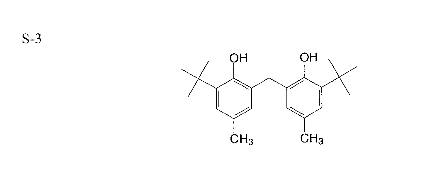
- Preferred antioxidants include hindered phenols in which at least one of the hydroxyl groups in the ortho position is substituted with a tertiary alkyl group, or at least one hydroxyl group in the phenols or hydroxybenzene is modified to other by an alkyl group.
- water-insoluble antioxidants useful in the invention include:
- the stabilizer particles used in the present invention may contain a dispersant or surfactant.
- the dispersant can be nonionic, anionic, or cationic, and can be polymeric.
- the surfactants may be used at levels as high as 20% of the stabilizer particle.
- Stabilizer particles employed in the invention can be formed by various methods known in the art. For example, they can be prepared by pulverizing and classifying the dry antioxidant or by spray drying of a solution containing antioxidant followed by re-dispersing the resultant particles in water using a dispersant.
- the particles can also be prepared by a suspension technique which consists of dissolving an antioxidant in, for example, a water immiscible solvent, dispersing the solution as fine liquid droplets in aqueous solution, and removing the solvent by evaporation or other suitable techniques.
- the particles can also be prepared by mechanically grinding an antioxidant material in water to a desired particle size in the presence a dispersant.
- the particles can also be prepared by the so-called "atmospheric emulsification” and pressure emulsification” techniques.
- the atmospheric emulsification process is used to prepare antioxidant dispersions for antioxidants with melting points below the boiling point of water.
- the process typically consists of melting the antioxidant and a surfactant together, and optionally adding a base. Hot water is then slowly added to the antioxidant solution with vigorous agitation.
- the antioxidant dispersion can also be made by adding a molten antioxidant/surfactant blend to boiling water with vigorous agitation.
- the pressure emulsification technique is generally used with an antioxidant having a melting point greater than 100°C.
- the stabilizer particles useful for the practice of the invention have a mean particle size of greater than 5 nm, preferably, a mean size of from 5 nm to 10 ⁇ m.
- the stabilizer particles When used in the image receiving layer, the stabilizer particles preferably have a mean size of from 5 nm to 500 nm, and more preferably from 5 nm to 300 nm.
- the coating weight of the stabilizer particles in the ink receiving layer varies from 10 mg/m 2 to 5 g/m 2 , and more preferably from 100 mg/m 2 to 2 g/m 2 .
- the image-receiving layer contains a dye fixing agent.
- the image-receiving layer preferably contains an anionic fixing agent.
- the image receiving layer preferably contains a cationic fixing agent.
- Amphoteric fixing agent can also be used for fixing either cationic dyes or anionic dyes.
- Such fixing agents can be water soluble or insoluble.
- the fixing agents are water-dispersible polymer particles.
- the thickness of the image-receiving layer may range from 5 to 40 ⁇ m, preferably from 10 to 20 ⁇ m.
- the coating thickness required is determined through the need for the coating to act as a sump for absorption of ink solvent and the need to hold the ink near the coating surface.
- the ink jet recording element may be subject to calendering or supercalendering to enhance surface smoothness.
- the ink jet recording element is subject to hot, softnip calendering at a temperature of 65°C and pressure of 14000 kg/m at a speed of from 0.15 m/s to 0.3 m/s.
- Coating compositions employed in the invention may be applied by any number of well known techniques, including dip-coating, wound-wire rod coating, doctor blade coating, rod coating, air knife coating, gravure and reverseroll coating, slide coating, bead coating, extrusion coating, curtain coating and the like.
- Known coating and drying methods are described in further detail in Research Disclosure no. 308119, published Dec. 1989, pages 1007 to 1008. Slide coating is preferred, in which the base layers and overcoat may be simultaneously applied. After coating, the layers are generally dried by simple evaporation, which may be accelerated by known techniques such as convection heating.
- crosslinkers which act upon the binder discussed above may be added in small quantities. Such an additive improves the cohesive strength of the layer.
- Crosslinkers such as carbodiimides, polyfunctional aziridines, aldehydes, isocyanates, epoxides, polyvalent metal cations, and the like may all be used.
- UV absorbers may also be added to the image-receiving layer as is well known in the art.
- Other additives include pH modifiers, adhesion promoters, rheology modifiers, surfactants, biocides, lubricants, dyes, optical brighteners, matte agents, antistatic agents, etc.
- additives known to those familiar with such art such as surfactants, defoamers, alcohol and the like may be used.
- a common level for coating aids is 0.01 to 0.30 % active coating aid based on the total solution weight.
- These coating aids can be nonionic, anionic, cationic or amphoteric. Specific examples are described in MCCUTCHEON's Volume 1: Emulsifiers and Detergents, 1995, North American Edition.
- the coating composition can be coated either from water or organic solvents, however water is preferred.
- the total solids content should be selected to yield a useful coating thickness in the most economical way, and for particulate coating formulations, solids contents from 10-40% are typical.
- the ink jet inks used to image the recording elements of the present invention are well-known in the art.
- the ink compositions used in ink jet printing typically are liquid compositions comprising a solvent or carrier liquid, dyes or pigments, humectants, organic solvents, detergents, thickeners, preservatives, and the like.
- the solvent or carrier liquid can be solely water or can be water mixed with other water-miscible solvents such as polyhydric alcohols.
- Inks in which organic materials such as polyhydric alcohols are the predominant carrier or solvent liquid may also be used. Particularly useful are mixed solvents of water and polyhydric alcohols.
- the dyes used in such compositions are typically watersoluble direct or acid type dyes.
- Such liquid compositions have been described extensively in the prior art including, for example, U.S. Patents 4,381,946; 4,239,543 and 4,781,758.
- a stabilizer particle dispersion refers to a suspension of stabilizer particles in an aqueous medium.
- a coating solution was prepared by mixing
- Base Layer 2 was prepared in a similar manner as Base Layer 1 except that it was prepared with SP-2 instead of SP-1
- Base Layer 3 was prepared in a similar manner as Base Layer 1 except it was prepared with SP-8 instead of SP-1.
- Base Layer 3 was prepared in a similar manner as Base Layer 1 except it was prepared without stabilizer particles.
- Image Receiving Layer Coating Solution 1 was prepared by combining alumina (Dispa1 14N4-80®, Condea Vista Co.), fumed alumina (Cab-O-Sperse® PG003, Cabot Corp.), poly(vinyl alcohol) (Gohsenol® GH-17, Nippon Gohsei Co.) and P-2 in a ratio of 66:20:4:10 to give an aqueous coating formulation of 15% solids by weight.
- Surfactants Zonyl® FSN (DuPont Co.) and Silwet L-7602® (Witco Corp.) were added in small amounts as coating aids.
- Image Receiving Coating Solution 2 was prepared by combing 269 g of the above modified Nalco 2329®, 82 g of P-1, and 1.12 g of surfactant Zonyl® FSN, and 44 g of a core/shell particle [silica core and poly(butyl acrylate) shell] as prepared by the procedure as described in the Example 1 of U.S. Patent Application Serial No 09/535,703, filed March 27, 2000.
- Image Receiving Coating Solution 3 was prepared the same as in Image receiving coating solution 2 except that the coating solution contained 90 g of SP-3.
- Image receiving coating solution 4 was prepared the same as in Image receiving coating solution 2 except that the coating solution contained 90 g of SP-4.
- Base layer coating solution 4 was coated onto a photographic base paper and dried at 90°C to give a dry thickness of 25 ⁇ m or a dry coating weight of 27 g/m 2 .
- Image receiving layer coating solution 1 was coated on the top of the base layer and dried at 90°C to give a dry thickness of 8 ⁇ m or a dry coating weight of 8.6 g/m 2 .
- Element 1 was prepared the same as Comparative Element 1 except that the base layer coating solution 3 was used.
- Element 3 was prepared the same as Comparative Element 1 except that the base layer coating solution 1 was used.
- Element C-2 was prepared the same as Element C-1 except that the imaging receiving layer coating solution 2 was used.
- Element 3 was prepared the same as Element 1 except that the image receiving layer coating solution 3 was used.
- Element 4 was prepared the same as Element 1 except that the image receiving layer coating solution 4 was used.
- the above recording elements were measured for 60° specular gloss using a Gardener® Gloss Meter.
- Element 5 was prepared the same as Element 3 except that the base layer coating solution 1 was used.
- Element 6 was prepared the same as Element 4 except that the base coating solution 2 was used.
Abstract
Description
- The present invention relates to an ink jet recording element containing a mixture of various particles and a printing method using the element.
- In a typical ink jet recording or printing system, ink droplets are ejected from a nozzle at high speed towards a recording element or medium to produce an image on the medium. The ink droplets, or recording liquid, generally comprise a recording agent, such as a dye or pigment, and a large amount of solvent. The solvent, or carrier liquid, typically is made up of water and an organic material such as a monohydric alcohol, a polyhydric alcohol or mixtures thereof.
- An ink jet recording element typically comprises a support having on at least one surface thereof an ink-receiving or image-receiving layer, and includes those intended for reflection viewing, which have an opaque support, and those intended for viewing by transmitted light, which have a transparent support.
- An important characteristic of ink jet recording elements is their need to dry quickly after printing. To this end, porous recording elements have been developed which provide nearly instantaneous drying as long as they have sufficient thickness and pore volume to effectively contain the liquid ink. For example, a porous recording element can be manufactured by cast coating, in which a particulate-containing coating is applied to a support and is dried in contact with a polished smooth surface.
- There are generally two types of ink-receiving layers (IRL's). The first type of IRL comprises a non-porous coating of a polymer with a high capacity for swelling and absorbing ink by molecular diffusion. Cationic or anionic substances are added to the coating to serve as a dye fixing agent or mordant for the cationic or anionic dye. This coating is optically transparent and very smooth, leading to a high glossy "photo-grade" receiver. The second type of IRL comprises a porous coating of inorganic, polymeric, or organic-inorganic composite particles, a polymeric binder, and additives such as dye-fixing agents or mordants. These particles can vary in chemical composition, size, shape, and intra-particle porosity. In this case, the printing liquid is absorbed into the open pores of the IRL to obtain a print which is instantaneously dry to the touch.
- A glossy, porous IRL usually contains a base layer and a glossy image-receiving layer. When coated on plain paper, the base layer is laid down underneath the glossy image-receiving layer. In order to provide a smooth, glossy surface on the image-receiving layer, special coating processes are often utilized, such as cast coating and film transfer coating. Calendering with heat and pressure is also used in combination with conventional blade, rod or air-knife coating on plain paper to produce gloss on the image-receiving layer.
- While glossy, porous IRL's have the ability to absorb high concentrations of ink instantly, they suffer from image fastness problems, such as fading due to exposure to radiation by daylight, tungsten light, fluorescent light, or ozone, as described by D.E. Bugner and C. Suminski, "Filtration and Reciprocity Effects on the Fade Rate of Inkjet Photographic Prints", Proceedings of IS&T's NIP16: International Conference on Digital Printing Technologies, Vancouver, BC, Oct. 2000. It is believed that the poor image fastness may be attributed to the greater permeability of the porous IRL's to oxygen and/other airborne reactants such as ozone.
- EP-A 1,034,940A1 discloses an ink jet-recording element wherein the image-receiving layer contains inorganic particles and an oil dispersion containing a hydrophobic antioxidant dispersed in a high-boiling organic solvent. However, there is a problem with this element in that the mechanical strength and surface scratch and rubbing resistance of the image-receiving layer are significantly reduced.
- It is an object of this invention to provide a glossy ink jet recording element that, when printed with dye-based inks, provides good surface gloss, fast drying time, and excellent image fastness.
- Still another object of the invention is to provide a printing method using the above described element.
- These and other objects are achieved in accordance with the invention which comprises an ink jet recording element comprising a support having thereon an image-receiving layer comprising inorganic particles and stabilizer particles, the stabilizer particles being free of any organic solvent and comprising greater than 80% by weight of a water-insoluble antioxidant and having a mean particle size of greater than 5 nm, the inorganic particles comprising greater than 50% by weight of the ink receiving layer.
- By use of the invention, an ink jet recording element is obtained that, when printed with dye-based inks, provides good surface gloss, fast drying time, and excellent image fastness.
- Another embodiment of the invention relates to an ink jet printing method comrising the steps of:
- A) providing an ink jet printer that is responsive to digital data signals;
- B) loading the printer with ink jet recording element described above;
- C) loading the printer with an ink jet ink composition; and
- D) printing on the image-receiving layer using the ink jet ink composition in response to the digital data signals.
-
- The support for the ink jet recording element used in the invention can be any of those usually used for ink jet receivers, such as resin-coated paper, paper, polyesters, or microporous materials such as polyethylene polymer-containing material sold by PPG Industries, Inc., Pittsburgh, Pennsylvania under the trade name of Teslin ®, Tyvek ® synthetic paper (DuPont Corp.), and OPPalyte® films (Mobi1 Chemical Co.) and other composite films listed in U.S. Patent 5,244,861. Opaque supports include plain paper, coated paper, synthetic paper, photographic paper support, melt-extrusion-coated paper, and laminated paper, such as biaxially oriented support laminates. Biaxially oriented support laminates are described in U.S. Patents 5,853,965; 5,866,282; 5,874,205; 5,888,643; 5,888,681; 5,888,683; and 5,888,714. These biaxially oriented supports include a paper base and a biaxially oriented polyolefin sheet, typically polypropylene, laminated to one or both sides of the paper base. Transparent supports include glass, cellulose derivatives, e.g., a cellulose ester, cellulose triacetate, cellulose diacetate, cellulose acetate propionate, cellulose acetate butyrate; polyesters, such as poly(ethylene terephthalate), poly(ethylene naphthalate), poly(1,4-cyclohexanedimethylene terephthalate), poly(butylene terephthalate), and copolymers thereof; polyimides; polyamides; polycarbonates; polystyrene; polyolefins, such as polyethylene or polypropylene; polysulfones; polyacrylates; polyetherimides; and mixtures thereof. The papers listed above include a broad range of papers, from high end papers, such as photographic paper to low end papers, such as newsprint. In a preferred embodiment, polyethylenecoated paper is employed.
- The support used in the invention may have a thickness of from 50 to 500 µm, preferably from 75 to 300 µm. Antioxidants, antistatic agents, plasticizers and other known additives may be incorporated into the support, if desired.
- In order to improve the adhesion of the ink-receiving layer to the support, the surface of the support may be subjected to a corona-discharge treatment prior to applying the image-receiving layer.
- In a preferred embodiment of the invention, the ink jet recording element of the invention contains a base layer between the support and the image-receiving layer. In another preferred embodiment, the base layer comprises inorganic particles and stabilizer particles, the stabilizer particles being free of any organic solvent and comprising greater than 80% by weight of a water-insoluble antioxidant and having a mean particle size of greater than 5 nm, and the inorganic particles comprising greater than 50% by weight of the base layer.
- As noted above, the image-receiving layer and preferably the base layer contain at least 50% by weight of inorganic particles. In a preferred embodiment, the inorganic particles comprise calcium carbonate, magnesium carbonate, kaolin, clay, talc, calcium sulfate, barium sulfate, titanium dioxide, zinc oxide, zinc hydroxide, zinc carbonate, aluminum silicate, calcium silicate, magnesium silicate, synthetic amorphous silica, fumed silica, colloidal silica, silica gel, alumina gel, fumed alumina, colloidal alumina, pseudo-boehmite, or zeolite. In another preferred embodiment, the inorganic particles have a mean particle size of from 50 nm to 500 nm.
- Porosity of the image-receiving layer is necessary in order to obtain very fast ink drying. The pores formed between the particles must be sufficiently large and interconnected so that the printing ink passes quickly through the layer and away from the outer surface to give the impression of fast drying. At the same time, the particles must be arranged in such a way so that the pores formed between them are sufficiently small so that they do not scatter visible light.
- In still another preferred embodiment, the image-receiving layer and base layer contains a binder such as a polymeric material and/or a latex material, such as poly(vinyl alcohol) and/or styrene-butadiene latex. In still another preferred embodiment, the binder in the base layer is present in an amount of from 5 to 20 weight %. In still another preferred embodiment, the thickness of the base layer may range from 5 µm to 50 µm, preferably from 20 to 40 µm.
- As noted above, the stabilizer particles useful in the invention comprise greater than 80% by weight of a water-insoluble antioxidant and have a mean particle size of greater than 5 nm. Examples of antioxidants which may be used in the invention include a substituted phenol, aromatic amine, piperidine-based amine, mercaptan, organic sulfide or organic phosphate. Preferred antioxidants include hindered phenols in which at least one of the hydroxyl groups in the ortho position is substituted with a tertiary alkyl group, or at least one hydroxyl group in the phenols or hydroxybenzene is modified to other by an alkyl group.
- Specific examples of water-insoluble antioxidants useful in the invention include:


- The stabilizer particles used in the present invention may contain a dispersant or surfactant. Depending on the intended applications, the dispersant can be nonionic, anionic, or cationic, and can be polymeric. The surfactants may be used at levels as high as 20% of the stabilizer particle.
- Stabilizer particles employed in the invention can be formed by various methods known in the art. For example, they can be prepared by pulverizing and classifying the dry antioxidant or by spray drying of a solution containing antioxidant followed by re-dispersing the resultant particles in water using a dispersant. The particles can also be prepared by a suspension technique which consists of dissolving an antioxidant in, for example, a water immiscible solvent, dispersing the solution as fine liquid droplets in aqueous solution, and removing the solvent by evaporation or other suitable techniques. The particles can also be prepared by mechanically grinding an antioxidant material in water to a desired particle size in the presence a dispersant. The particles can also be prepared by the so-called "atmospheric emulsification" and pressure emulsification" techniques. The atmospheric emulsification process is used to prepare antioxidant dispersions for antioxidants with melting points below the boiling point of water. The process typically consists of melting the antioxidant and a surfactant together, and optionally adding a base. Hot water is then slowly added to the antioxidant solution with vigorous agitation. The antioxidant dispersion can also be made by adding a molten antioxidant/surfactant blend to boiling water with vigorous agitation. The pressure emulsification technique is generally used with an antioxidant having a melting point greater than 100°C.
- The stabilizer particles useful for the practice of the invention have a mean particle size of greater than 5 nm, preferably, a mean size of from 5 nm to 10 µm. When used in the image receiving layer, the stabilizer particles preferably have a mean size of from 5 nm to 500 nm, and more preferably from 5 nm to 300 nm. In a preferred embodiment, the coating weight of the stabilizer particles in the ink receiving layer varies from 10 mg/m2 to 5 g/m2, and more preferably from 100 mg/m2 to 2 g/m2.
- In another preferred embodiment, the image-receiving layer contains a dye fixing agent. For fixing cationic dyes, the image-receiving layer preferably contains an anionic fixing agent. For fixing anionic dyes, the image receiving layer preferably contains a cationic fixing agent. Amphoteric fixing agent can also be used for fixing either cationic dyes or anionic dyes. Such fixing agents can be water soluble or insoluble. Preferably, the fixing agents are water-dispersible polymer particles.
- The thickness of the image-receiving layer may range from 5 to 40 µm, preferably from 10 to 20 µm. The coating thickness required is determined through the need for the coating to act as a sump for absorption of ink solvent and the need to hold the ink near the coating surface.
- After coating, the ink jet recording element may be subject to calendering or supercalendering to enhance surface smoothness. In a preferred embodiment of the invention, the ink jet recording element is subject to hot, softnip calendering at a temperature of 65°C and pressure of 14000 kg/m at a speed of from 0.15 m/s to 0.3 m/s.
- Coating compositions employed in the invention may be applied by any number of well known techniques, including dip-coating, wound-wire rod coating, doctor blade coating, rod coating, air knife coating, gravure and reverseroll coating, slide coating, bead coating, extrusion coating, curtain coating and the like. Known coating and drying methods are described in further detail in Research Disclosure no. 308119, published Dec. 1989, pages 1007 to 1008. Slide coating is preferred, in which the base layers and overcoat may be simultaneously applied. After coating, the layers are generally dried by simple evaporation, which may be accelerated by known techniques such as convection heating.
- In order to impart mechanical durability to an ink jet recording element, crosslinkers which act upon the binder discussed above may be added in small quantities. Such an additive improves the cohesive strength of the layer. Crosslinkers such as carbodiimides, polyfunctional aziridines, aldehydes, isocyanates, epoxides, polyvalent metal cations, and the like may all be used.
- To improve colorant fade, UV absorbers, radical quenchers or antioxidants may also be added to the image-receiving layer as is well known in the art. Other additives include pH modifiers, adhesion promoters, rheology modifiers, surfactants, biocides, lubricants, dyes, optical brighteners, matte agents, antistatic agents, etc. In order to obtain adequate coatability, additives known to those familiar with such art such as surfactants, defoamers, alcohol and the like may be used. A common level for coating aids is 0.01 to 0.30 % active coating aid based on the total solution weight. These coating aids can be nonionic, anionic, cationic or amphoteric. Specific examples are described in MCCUTCHEON's Volume 1: Emulsifiers and Detergents, 1995, North American Edition.
- The coating composition can be coated either from water or organic solvents, however water is preferred. The total solids content should be selected to yield a useful coating thickness in the most economical way, and for particulate coating formulations, solids contents from 10-40% are typical.
- Ink jet inks used to image the recording elements of the present invention are well-known in the art. The ink compositions used in ink jet printing typically are liquid compositions comprising a solvent or carrier liquid, dyes or pigments, humectants, organic solvents, detergents, thickeners, preservatives, and the like. The solvent or carrier liquid can be solely water or can be water mixed with other water-miscible solvents such as polyhydric alcohols. Inks in which organic materials such as polyhydric alcohols are the predominant carrier or solvent liquid may also be used. Particularly useful are mixed solvents of water and polyhydric alcohols. The dyes used in such compositions are typically watersoluble direct or acid type dyes. Such liquid compositions have been described extensively in the prior art including, for example, U.S. Patents 4,381,946; 4,239,543 and 4,781,758.
- The following examples are provided to illustrate the invention.
- A stabilizer particle dispersion refers to a suspension of stabilizer particles in an aqueous medium.
- SP-1:In a container, solution A was prepared by combining 240 g of S-11 (illustrated above) with 360 g of ethyl acetate and heating to 50°C with mixing to dissolve the antioxidant. In a separate container, solution B was prepared by combining 250 g of a 20% polyvinyl alcohol solution of Airvol 205® (Air Products Corp.), 140 g of Alkanol XC® anionic surfactant (DuPont Corp.), 4 g of a 0.7% Kathon LX® solution (Rohm and Haas) and 1006 g of deionized water and heating to 45°C with mixing.A premix (a crude oil-in-water emulsion) was formed by mixing solution A and solution B with a Silverson rotor-stator device at 5,000 rpm and mixing continued for two minutes. Then the premix was passed through a Crepaco high energy homogenizer one time at 1.4 x 10⁶ kg/m2 (2,000 psi) and the fine emulsion was collected in a glass round-bottom flask. The emulsion was rotary evaporated at 65°C under vacuum to remove ethyl acetate and some water. The resulting fine particles of antioxidant in water were sized on a Microtrac -UPA 150 and found to have a mean volume average diameter of 220 nm.
- SP-2:SP-2 was prepared in a similar manner as SP-1 except stabilizer S-20 was used instead of S-11.
- SP-3:SP-3 was prepared in a similar manner as SP-1 except that cetyltrimethylammonium bromide (CTAB) was used instead of the Alkanol XC ® surfactant
- SP-4:SP-4 was prepared in a similar manner as SP-2 except that CTAB was used instead of the Alkanol XC® surfactant.
- SP-5:SP-5 was prepared in a similar manner as SP-1 except that polyvinyl alcohol was not used.
- SP-6:SP-6 was prepared in a similar manner as SP-2 except that polyvinyl alcohol was not used.
- SP-7:SP-7 was prepared in a similar manner as SP-5 except that it contained a mixture of S-11 and S-41 at a ratio of 90:10 instead of S-11.
- SP-8:SP-8 was prepared in a similar manner as SP-3 except that contained a mixture of S-11 and S-41 at a ratio of 90:10 instead of S-11.
-
- To 325 g of Nalco 2329 ® solution (40% solids from Nalco Co.) was added at room temperature dropwise, 1.29 g of aminopropyl methyl dimethoxysilane under stirring. The reaction was allowed to continue at room temperature for 24 hours before use.
- A coating solution was prepared by mixing
- (1) 242.6 g of water
- (2) 225.6 g of Albagloss-s® precipitated calcium carbonate (Specialty Minerals Inc.) at 70 wt. %
- (3) 8.75 g of silica gel Crosfield 23F ® (Crosfield Ltd.)
- (4) 8.75 g of Airvol 125® poly(vinyl alcohol) (Air Product) at 10 wt. %
- (5) 14.3 g of styrene-butadiene latex CP692NA ® (Dow Chemicals Corp.) at 50 wt. %
- (6) 75 g of SP-1
-
- Base Layer 2 was prepared in a similar manner as Base Layer 1 except that it was prepared with SP-2 instead of SP-1
- Base Layer 3 was prepared in a similar manner as Base Layer 1 except it was prepared with SP-8 instead of SP-1.
- Base Layer 3 was prepared in a similar manner as Base Layer 1 except it was prepared without stabilizer particles.
- Image Receiving Layer Coating Solution 1 was prepared by combining alumina (Dispa1 14N4-80®, Condea Vista Co.), fumed alumina (Cab-O-Sperse® PG003, Cabot Corp.), poly(vinyl alcohol) (Gohsenol® GH-17, Nippon Gohsei Co.) and P-2 in a ratio of 66:20:4:10 to give an aqueous coating formulation of 15% solids by weight. Surfactants Zonyl® FSN (DuPont Co.) and Silwet L-7602® (Witco Corp.) were added in small amounts as coating aids.
- Image Receiving Coating Solution 2 was prepared by combing 269 g of the above modified Nalco 2329®, 82 g of P-1, and 1.12 g of surfactant Zonyl® FSN, and 44 g of a core/shell particle [silica core and poly(butyl acrylate) shell] as prepared by the procedure as described in the Example 1 of U.S. Patent Application Serial No 09/535,703, filed March 27, 2000.
- Image Receiving Coating Solution 3 was prepared the same as in Image receiving coating solution 2 except that the coating solution contained 90 g of SP-3.
- Image receiving coating solution 4 was prepared the same as in Image receiving coating solution 2 except that the coating solution contained 90 g of SP-4.
- Base layer coating solution 4 was coated onto a photographic base paper and dried at 90°C to give a dry thickness of 25 µm or a dry coating weight of 27 g/m2.
- Image receiving layer coating solution 1 was coated on the top of the base layer and dried at 90°C to give a dry thickness of 8 µm or a dry coating weight of 8.6 g/m2.
- Element 1 was prepared the same as Comparative Element 1 except that the base layer coating solution 3 was used.
- Element 3 was prepared the same as Comparative Element 1 except that the base layer coating solution 1 was used.
- The above elements were printed using a Kodak PPM 200® printer using color cartridges number 195-1730. The image consisted of adjacent patches of cyan, magenta, yellow, black, green, red and blue patches, each patch being in the form of a rectangle 0.4 cm in width and 1.0 cm in length. The images were then subjected to an ambient fluorescence white light fading test for up to one week. The reflection density nearest to 1.0 was compared before and after fade and a percent density loss was calculated for the yellow dye with each receiver element. The following results were obtained:
Element Magenta Density Loss (%) Black Density Loss (%) C-1 20 18 1 11 8 2 11 7 - The above results show that the elements prepared in accordance with the invention had less dye loss as compared to the comparative element.
- Element C-2 was prepared the same as Element C-1 except that the imaging receiving layer coating solution 2 was used.
- Element 3 was prepared the same as Element 1 except that the image receiving layer coating solution 3 was used.
- Element 4 was prepared the same as Element 1 except that the image receiving layer coating solution 4 was used.
- The above recording elements were measured for 60° specular gloss using a Gardener® Gloss Meter.
- The above elements were then printed and tested as in Example 1. The following results were obtained:
Element Gloss Gloss Magenta Density
Loss (%)1Magenta Density
Loss (%) 2C-2 30 52 64.6 58.1 3 41 61 17.2 25.3 4 38 62 14 22.4 - The above results show that the elements of the invention had less magenta density loss before and after calendering as compared to the comparative element.
- The above printed elements were then exposed to ambient ozone for up to two weeks. The reflection density nearest to 1.0 was compared before and after exposure to ozone (50 ppb concentration) for 3 and 5 days, respectively, and a percent density loss was calculated for the yellow dye with each receiver element. The following results were obtained:
Element Magenta Density Loss (%) Cyan Density Loss (%) 3 days 5 days 3 days 5 days C-2 42 62 6 13 3 25 36 3 4 4 23 37 3 5 - The above results show that the elements of the invention had less magenta and cyan density loss when exposed to ozone as compared to the comparative element.
- Element 5 was prepared the same as Element 3 except that the base layer coating solution 1 was used.
- Element 6 was prepared the same as Element 4 except that the base coating solution 2 was used.
- The above elements were subjected to the accelerated ozone test as in Example 2. The following results were obtained:
Element Magenta Density Loss (%) Cyan Density Loss (%) 5 days 7 days 5 days 7 days 5 15 36 2 8 6 12 23 2 5 - The above results show that the elements of the invention had good resistance to ozone fade.
Claims (10)
- An ink jet recording element comprising a support having thereon an image-receiving layer comprising inorganic particles and stabilizer particles, said stabilizer particles being free of any organic solvent and comprising greater than 80% by weight of a water-insoluble antioxidant and having a mean particle size of greater than 5 nm, said inorganic particles comprising greater than 50% by weight of said image-receiving layer.
- The recording element of Claim 1 which contains a base layer between said support and said image-receiving layer.
- The recording element of Claim 2 wherein said base layer comprises inorganic particles and stabilizer particles, said stabilizer particles being free of any organic solvent and comprising greater than 80% by weight of a water-insoluble antioxidant and having a mean particle size of greater than 5 nm, said inorganic particles comprising greater than 50% by weight of said base layer
- The recording element of Claim 2 wherein said base layer also contains a binder in an amount of from 5 to 20 weight %.
- The recording element of Claim 2 wherein said support is coated with said base layer and said image-receiving layer and is then calendered.
- The recording element of Claim 1 wherein said inorganic particles comprise calcium carbonate, magnesium carbonate, kaolin, clay, talc, calcium sulfate, barium sulfate, titanium dioxide, zinc oxide, zinc hydroxide, zinc carbonate, aluminum silicate, calcium silicate, magnesium silicate, synthetic amorphous silica, fumed silica, colloidal silica, silica gel, alumina gel, fumed alumina, colloidal alumina, pseudo-boehmite, or zeolite.
- The recording element of Claim 1 wherein said inorganic particles have a mean particle size of from 50 to 500 nm.
- The recording element of Claim 1 wherein said image-receiving layer also contains a binder in an amount of from 5 to 20 weight %.
- The recording element of Claim 8 wherein said binder is a hydrophilic polymer.
- An ink jet printing method comprising the steps of:A) providing an ink jet printer that is responsive to digital data signals;B) loading said printer with the ink jet recording element of Claim 1;C) loading said printer with an ink jet ink composition; andD) printing on said image-receiving layer using said ink jet ink composition in response to said digital data signals.
Applications Claiming Priority (4)
| Application Number | Priority Date | Filing Date | Title |
|---|---|---|---|
| US10/021,341 US7901748B2 (en) | 2001-12-12 | 2001-12-12 | Ink jet recording element |
| US21341 | 2001-12-12 | ||
| US10/017,937 US20030137574A1 (en) | 2001-12-12 | 2001-12-12 | Ink jet printing method |
| US17937 | 2001-12-12 |
Publications (2)
| Publication Number | Publication Date |
|---|---|
| EP1319517A1 true EP1319517A1 (en) | 2003-06-18 |
| EP1319517B1 EP1319517B1 (en) | 2006-01-18 |
Family
ID=26690528
Family Applications (1)
| Application Number | Title | Priority Date | Filing Date |
|---|---|---|---|
| EP20020079892 Expired - Fee Related EP1319517B1 (en) | 2001-12-12 | 2002-11-25 | Ink jet recording element and printing method |
Country Status (3)
| Country | Link |
|---|---|
| EP (1) | EP1319517B1 (en) |
| JP (1) | JP2003191635A (en) |
| DE (1) | DE60208757T2 (en) |
Cited By (4)
| Publication number | Priority date | Publication date | Assignee | Title |
|---|---|---|---|---|
| EP1493591A2 (en) * | 2003-07-02 | 2005-01-05 | Hewlett-Packard Development Company, L.P. | Inkjet recording materials containing siloxane copolymer surfactants |
| WO2005009746A1 (en) * | 2003-07-18 | 2005-02-03 | Eastman Kodak Company | Fluorosurfactant and colloidal particles in imaging element |
| WO2005009747A1 (en) * | 2003-07-18 | 2005-02-03 | Eastman Kodak Company | Ink jet media with core shell particles |
| US7906185B2 (en) | 2007-01-30 | 2011-03-15 | Hewlett-Packard Development Company, L.P. | Inkjet recording media |
Citations (7)
| Publication number | Priority date | Publication date | Assignee | Title |
|---|---|---|---|---|
| JPH01170672A (en) * | 1987-12-26 | 1989-07-05 | Canon Inc | Recording solution and image formation using said solution |
| EP0903246A2 (en) * | 1997-09-17 | 1999-03-24 | Oji Paper Co., Ltd. | Ink-jet recording material containing ultraviolet ray-absorber |
| EP0984047A1 (en) * | 1998-09-04 | 2000-03-08 | Trident International, Inc. | High resolution pigment ink for impulse ink jet printing |
| US6056812A (en) * | 1998-05-05 | 2000-05-02 | Hewlett-Packard Company | Composition to improve colorfastness of a printed image |
| EP1034940A1 (en) * | 1999-03-09 | 2000-09-13 | Konica Corporation | Ink-jet recording sheet containing dicyandiamide-based copolymers |
| EP1138509A2 (en) * | 2000-03-28 | 2001-10-04 | Mitsubishi Paper Mills Limited | Ink-jet recording material and ink-jet recording method |
| EP1180436A1 (en) * | 2000-08-15 | 2002-02-20 | Dainippon Ink And Chemicals, Inc. | Composition for ink-receiving layer, recording material and printed matter obtained using the same |
-
2002
- 2002-11-25 DE DE2002608757 patent/DE60208757T2/en not_active Expired - Lifetime
- 2002-11-25 EP EP20020079892 patent/EP1319517B1/en not_active Expired - Fee Related
- 2002-12-11 JP JP2002359041A patent/JP2003191635A/en active Pending
Patent Citations (7)
| Publication number | Priority date | Publication date | Assignee | Title |
|---|---|---|---|---|
| JPH01170672A (en) * | 1987-12-26 | 1989-07-05 | Canon Inc | Recording solution and image formation using said solution |
| EP0903246A2 (en) * | 1997-09-17 | 1999-03-24 | Oji Paper Co., Ltd. | Ink-jet recording material containing ultraviolet ray-absorber |
| US6056812A (en) * | 1998-05-05 | 2000-05-02 | Hewlett-Packard Company | Composition to improve colorfastness of a printed image |
| EP0984047A1 (en) * | 1998-09-04 | 2000-03-08 | Trident International, Inc. | High resolution pigment ink for impulse ink jet printing |
| EP1034940A1 (en) * | 1999-03-09 | 2000-09-13 | Konica Corporation | Ink-jet recording sheet containing dicyandiamide-based copolymers |
| EP1138509A2 (en) * | 2000-03-28 | 2001-10-04 | Mitsubishi Paper Mills Limited | Ink-jet recording material and ink-jet recording method |
| EP1180436A1 (en) * | 2000-08-15 | 2002-02-20 | Dainippon Ink And Chemicals, Inc. | Composition for ink-receiving layer, recording material and printed matter obtained using the same |
Non-Patent Citations (1)
| Title |
|---|
| DATABASE WPI Section Ch Week 198933, Derwent World Patents Index; Class G02, AN 1989-237031, XP002234414 * |
Cited By (7)
| Publication number | Priority date | Publication date | Assignee | Title |
|---|---|---|---|---|
| EP1493591A2 (en) * | 2003-07-02 | 2005-01-05 | Hewlett-Packard Development Company, L.P. | Inkjet recording materials containing siloxane copolymer surfactants |
| EP1493591A3 (en) * | 2003-07-02 | 2005-12-14 | Hewlett-Packard Development Company, L.P. | Inkjet recording materials containing siloxane copolymer surfactants |
| WO2005009746A1 (en) * | 2003-07-18 | 2005-02-03 | Eastman Kodak Company | Fluorosurfactant and colloidal particles in imaging element |
| WO2005009747A1 (en) * | 2003-07-18 | 2005-02-03 | Eastman Kodak Company | Ink jet media with core shell particles |
| US7223454B1 (en) | 2003-07-18 | 2007-05-29 | Eastman Kodak Company | Ink jet recording element with core shell particles |
| US7695783B2 (en) | 2003-07-18 | 2010-04-13 | Eastman Kodak Company | Image-recording element with fluorosurfactant and colloidal particles |
| US7906185B2 (en) | 2007-01-30 | 2011-03-15 | Hewlett-Packard Development Company, L.P. | Inkjet recording media |
Also Published As
| Publication number | Publication date |
|---|---|
| DE60208757T2 (en) | 2006-09-14 |
| DE60208757D1 (en) | 2006-04-06 |
| EP1319517B1 (en) | 2006-01-18 |
| JP2003191635A (en) | 2003-07-09 |
Similar Documents
| Publication | Publication Date | Title |
|---|---|---|
| US6689430B2 (en) | Ink jet recording element | |
| US6770336B2 (en) | Ink jet recording element | |
| US6641875B2 (en) | Ink jet recording element | |
| US6447110B1 (en) | Ink jet printing method | |
| EP1288012B1 (en) | Ink jet recording element and printing method | |
| US6634743B2 (en) | Method for increasing the diameter of an ink jet ink dot | |
| EP1319517B1 (en) | Ink jet recording element and printing method | |
| US20030137574A1 (en) | Ink jet printing method | |
| US6527388B1 (en) | Ink jet printing method | |
| EP1386751A2 (en) | Ink jet recording element and printing method | |
| US7901748B2 (en) | Ink jet recording element | |
| US6443570B1 (en) | Ink jet printing method | |
| EP1226970B1 (en) | Ink jet recording element and printing method | |
| US6821586B2 (en) | Ink jet recording element | |
| EP1319516B1 (en) | Ink jet recording element and printing method | |
| EP1288011B1 (en) | Ink jet recording element and printing method | |
| EP1288008B1 (en) | Ink jet recording element and printing method | |
| EP1319518B1 (en) | Ink jet recording element and printing method | |
| US6565205B2 (en) | Ink jet printing method | |
| US20030108691A1 (en) | Ink jet printing method | |
| EP1319519A2 (en) | Ink jet recording element and printing method | |
| US6815020B2 (en) | Ink jet recording element | |
| EP1288010B1 (en) | Ink jet recording element and printing method | |
| US6431701B1 (en) | Ink jet printing method | |
| US20030108690A1 (en) | Ink jet recording element |
Legal Events
| Date | Code | Title | Description |
|---|---|---|---|
| PUAI | Public reference made under article 153(3) epc to a published international application that has entered the european phase |
Free format text: ORIGINAL CODE: 0009012 |
|
| AK | Designated contracting states |
Designated state(s): AT BE BG CH CY CZ DE DK EE ES FI FR GB GR IE IT LI LU MC NL PT SE SK TR |
|
| AX | Request for extension of the european patent |
Extension state: AL LT LV MK RO SI |
|
| 17P | Request for examination filed |
Effective date: 20031114 |
|
| AKX | Designation fees paid |
Designated state(s): DE FR GB |
|
| 17Q | First examination report despatched |
Effective date: 20040617 |
|
| GRAP | Despatch of communication of intention to grant a patent |
Free format text: ORIGINAL CODE: EPIDOSNIGR1 |
|
| GRAS | Grant fee paid |
Free format text: ORIGINAL CODE: EPIDOSNIGR3 |
|
| GRAA | (expected) grant |
Free format text: ORIGINAL CODE: 0009210 |
|
| AK | Designated contracting states |
Kind code of ref document: B1 Designated state(s): DE FR GB |
|
| REG | Reference to a national code |
Ref country code: GB Ref legal event code: FG4D |
|
| REF | Corresponds to: |
Ref document number: 60208757 Country of ref document: DE Date of ref document: 20060406 Kind code of ref document: P |
|
| ET | Fr: translation filed | ||
| PLBE | No opposition filed within time limit |
Free format text: ORIGINAL CODE: 0009261 |
|
| STAA | Information on the status of an ep patent application or granted ep patent |
Free format text: STATUS: NO OPPOSITION FILED WITHIN TIME LIMIT |
|
| 26N | No opposition filed |
Effective date: 20061019 |
|
| PGFP | Annual fee paid to national office [announced via postgrant information from national office to epo] |
Ref country code: FR Payment date: 20121113 Year of fee payment: 11 Ref country code: DE Payment date: 20121130 Year of fee payment: 11 |
|
| PGFP | Annual fee paid to national office [announced via postgrant information from national office to epo] |
Ref country code: GB Payment date: 20121025 Year of fee payment: 11 |
|
| REG | Reference to a national code |
Ref country code: DE Ref legal event code: R119 Ref document number: 60208757 Country of ref document: DE |
|
| GBPC | Gb: european patent ceased through non-payment of renewal fee |
Effective date: 20131125 |
|
| REG | Reference to a national code |
Ref country code: FR Ref legal event code: ST Effective date: 20140731 |
|
| PG25 | Lapsed in a contracting state [announced via postgrant information from national office to epo] |
Ref country code: DE Free format text: LAPSE BECAUSE OF NON-PAYMENT OF DUE FEES Effective date: 20140603 |
|
| REG | Reference to a national code |
Ref country code: DE Ref legal event code: R119 Ref document number: 60208757 Country of ref document: DE Effective date: 20140603 |
|
| PG25 | Lapsed in a contracting state [announced via postgrant information from national office to epo] |
Ref country code: FR Free format text: LAPSE BECAUSE OF NON-PAYMENT OF DUE FEES Effective date: 20131202 Ref country code: GB Free format text: LAPSE BECAUSE OF NON-PAYMENT OF DUE FEES Effective date: 20131125 |