EP1318632B1 - Packet data transmission scheduling technique - Google Patents
Packet data transmission scheduling technique Download PDFInfo
- Publication number
- EP1318632B1 EP1318632B1 EP02026087A EP02026087A EP1318632B1 EP 1318632 B1 EP1318632 B1 EP 1318632B1 EP 02026087 A EP02026087 A EP 02026087A EP 02026087 A EP02026087 A EP 02026087A EP 1318632 B1 EP1318632 B1 EP 1318632B1
- Authority
- EP
- European Patent Office
- Prior art keywords
- data
- real
- delay
- layer
- time data
- Prior art date
- Legal status (The legal status is an assumption and is not a legal conclusion. Google has not performed a legal analysis and makes no representation as to the accuracy of the status listed.)
- Revoked
Links
Images


Classifications
-
- H—ELECTRICITY
- H04—ELECTRIC COMMUNICATION TECHNIQUE
- H04L—TRANSMISSION OF DIGITAL INFORMATION, e.g. TELEGRAPHIC COMMUNICATION
- H04L47/00—Traffic control in data switching networks
- H04L47/10—Flow control; Congestion control
- H04L47/24—Traffic characterised by specific attributes, e.g. priority or QoS
- H04L47/2416—Real-time traffic
-
- H—ELECTRICITY
- H04—ELECTRIC COMMUNICATION TECHNIQUE
- H04W—WIRELESS COMMUNICATION NETWORKS
- H04W72/00—Local resource management
- H04W72/50—Allocation or scheduling criteria for wireless resources
- H04W72/56—Allocation or scheduling criteria for wireless resources based on priority criteria
- H04W72/566—Allocation or scheduling criteria for wireless resources based on priority criteria of the information or information source or recipient
- H04W72/569—Allocation or scheduling criteria for wireless resources based on priority criteria of the information or information source or recipient of the traffic information
-
- H—ELECTRICITY
- H04—ELECTRIC COMMUNICATION TECHNIQUE
- H04L—TRANSMISSION OF DIGITAL INFORMATION, e.g. TELEGRAPHIC COMMUNICATION
- H04L47/00—Traffic control in data switching networks
- H04L47/10—Flow control; Congestion control
-
- H—ELECTRICITY
- H04—ELECTRIC COMMUNICATION TECHNIQUE
- H04L—TRANSMISSION OF DIGITAL INFORMATION, e.g. TELEGRAPHIC COMMUNICATION
- H04L47/00—Traffic control in data switching networks
- H04L47/10—Flow control; Congestion control
- H04L47/24—Traffic characterised by specific attributes, e.g. priority or QoS
- H04L47/2425—Traffic characterised by specific attributes, e.g. priority or QoS for supporting services specification, e.g. SLA
- H04L47/2433—Allocation of priorities to traffic types
-
- H—ELECTRICITY
- H04—ELECTRIC COMMUNICATION TECHNIQUE
- H04L—TRANSMISSION OF DIGITAL INFORMATION, e.g. TELEGRAPHIC COMMUNICATION
- H04L47/00—Traffic control in data switching networks
- H04L47/10—Flow control; Congestion control
- H04L47/24—Traffic characterised by specific attributes, e.g. priority or QoS
- H04L47/2458—Modification of priorities while in transit
-
- H—ELECTRICITY
- H04—ELECTRIC COMMUNICATION TECHNIQUE
- H04L—TRANSMISSION OF DIGITAL INFORMATION, e.g. TELEGRAPHIC COMMUNICATION
- H04L47/00—Traffic control in data switching networks
- H04L47/10—Flow control; Congestion control
- H04L47/28—Flow control; Congestion control in relation to timing considerations
- H04L47/283—Flow control; Congestion control in relation to timing considerations in response to processing delays, e.g. caused by jitter or round trip time [RTT]
-
- H—ELECTRICITY
- H04—ELECTRIC COMMUNICATION TECHNIQUE
- H04L—TRANSMISSION OF DIGITAL INFORMATION, e.g. TELEGRAPHIC COMMUNICATION
- H04L47/00—Traffic control in data switching networks
- H04L47/10—Flow control; Congestion control
- H04L47/28—Flow control; Congestion control in relation to timing considerations
- H04L47/286—Time to live
-
- H—ELECTRICITY
- H04—ELECTRIC COMMUNICATION TECHNIQUE
- H04L—TRANSMISSION OF DIGITAL INFORMATION, e.g. TELEGRAPHIC COMMUNICATION
- H04L47/00—Traffic control in data switching networks
- H04L47/10—Flow control; Congestion control
- H04L47/30—Flow control; Congestion control in combination with information about buffer occupancy at either end or at transit nodes
-
- H—ELECTRICITY
- H04—ELECTRIC COMMUNICATION TECHNIQUE
- H04L—TRANSMISSION OF DIGITAL INFORMATION, e.g. TELEGRAPHIC COMMUNICATION
- H04L47/00—Traffic control in data switching networks
- H04L47/10—Flow control; Congestion control
- H04L47/34—Flow control; Congestion control ensuring sequence integrity, e.g. using sequence numbers
-
- H—ELECTRICITY
- H04—ELECTRIC COMMUNICATION TECHNIQUE
- H04L—TRANSMISSION OF DIGITAL INFORMATION, e.g. TELEGRAPHIC COMMUNICATION
- H04L47/00—Traffic control in data switching networks
- H04L47/10—Flow control; Congestion control
- H04L47/36—Flow control; Congestion control by determining packet size, e.g. maximum transfer unit [MTU]
-
- H—ELECTRICITY
- H04—ELECTRIC COMMUNICATION TECHNIQUE
- H04W—WIRELESS COMMUNICATION NETWORKS
- H04W28/00—Network traffic management; Network resource management
- H04W28/02—Traffic management, e.g. flow control or congestion control
-
- H—ELECTRICITY
- H04—ELECTRIC COMMUNICATION TECHNIQUE
- H04W—WIRELESS COMMUNICATION NETWORKS
- H04W8/00—Network data management
- H04W8/02—Processing of mobility data, e.g. registration information at HLR [Home Location Register] or VLR [Visitor Location Register]; Transfer of mobility data, e.g. between HLR, VLR or external networks
- H04W8/04—Registration at HLR or HSS [Home Subscriber Server]
-
- H—ELECTRICITY
- H04—ELECTRIC COMMUNICATION TECHNIQUE
- H04W—WIRELESS COMMUNICATION NETWORKS
- H04W92/00—Interfaces specially adapted for wireless communication networks
- H04W92/04—Interfaces between hierarchically different network devices
- H04W92/12—Interfaces between hierarchically different network devices between access points and access point controllers
Definitions
- the present invention relates to a wireless communication system, and more particularly to packet transmission scheduling of the High Speed Downlink Packet Access (HSDPA) system operated in a UMTS terrestrial radio access network (UTRAN).
- HSDPA High Speed Downlink Packet Access
- UTRAN UMTS terrestrial radio access network
- the Universal Mobile Telecommunications System is a third generation mobile communication system, which evolved from a Global System for Mobile Communications (GSM) and a European style mobile communication standard. It is intended to provide improved mobile communication services based on a GSM core network (CN) and Wideband Code Division Multiple Access (WCDMA) access technology.
- GSM Global System for Mobile Communications
- CN GSM core network
- WCDMA Wideband Code Division Multiple Access
- IMT-2000 systems For the purpose of making a standard for third generation mobile communication systems (IMT-2000 systems) based on GSM core network and WCDMA radio access technology, a group of standard developing organizations, including ETSI of Europe, ARIB/TTC of Japan, T1 of U.S., and TTA of Korea, established the Third Generation Partnership Project (3GPP).
- 3GPP Third Generation Partnership Project
- TSGs Technical Specification Groups
- Each TSG is responsible for approving, developing, and managing specifications related to a pertinent area.
- the Radio Access Network (RAN) group has developed Functions, requirements, and interface specifications related to UE and UMTS terrestrial radio access network (UTRAN) in order to establish a new radio access network specification to the third generation mobile communication system.
- RAN Radio Access Network
- the TSG-RAN group consists of one plenary group and four working groups.
- Working Group 1 has been developing specifications for a physical layer (Layer 1) and WG2 has been specifying functions of a data link layer (Layer 2) between UE and UTRAN.
- WG3 has been developing specifications for interfaces among Node Bs (the Node B is a kind of base station in the wireless communications), Radio Network Controllers (RNCs), and the core network.
- WG4 has been discussing requirements for radio link performance and radio resource management.
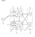
- Figure 1 illustrates a structure of the UTRAN defined in 3GPP.
- the UTRAN 110 includes at least one radio network sub-systems (RNSs) 120 and 130,
- RNS 120, 130 includes an RNC 121, 131 and at least one or more Node Bs 122, 123, 132, 133.
- Node B 122 is managed by RNC 121, and receives information transmitted from the physical layer of the UE 150 through an uplink channel and transmits a data to the UE 150 through a downlink channel.
- the Node B acts as an access point of the UTRAN from the UE point of view.
- the RNCs 121 and 131 allocate and manage radio resources of the UMTS and are connected to a suitable clement of the core network 140 depending on types of services provided to users.
- the RNCs 121 and 131 are connected to a mobile switching center (MSC) 141 for a circuit-switched communication such as a voice call service, and are connected to a Serving GPRS Support Node (SGSN) 142 for packet switched communication such as a wireless Internet service.
- MSC mobile switching center
- SGSN Serving GPRS Support Node
- the RNC in charge of a direct management of the Node B is called a Control RNC (CRNC).
- the CRNC manages common radio resources.
- the RNC that manages dedicated radio resources for a specific UE is called a Serving RNC (SRNC).
- SRNC Serving RNC
- the CRNC and the SRNC can be co-located in the same physical node. However, if the UE has been moved to an area of a new RNC that is different from SRNC, the CRNC and the SRNC may be located at physically different places.
- the interface between a Node B and a RNC is called a lub interface, and an interface between RNCs is called a lur interface. And an interface between the RNC and the core network is called a lu interface.
- Figure 2 illustrates a protocol structure of a radio interface protocol defined in the 3GPP.
- the radio interface protocol horizontally includes a physical layer, a data link layer, and a network layer, and is vertically divided into a control plane for transmission of control information (signaling) and a user plane for transmission of data information.
- the user plane is a region through which user traffic such as voice information or IP (Internet Protocol) packets is transmitted
- the control plane is a region through which control information required for network maintenance and management is transmitted.
- the physical layer handles transmission of data using a wireless physical channel between the UE and the UTRAN.
- the typical functions of the physical layer include data multiplexing, channel coding, spreading, and modulation.
- the physical layer exchanges information with a Medium Access Control (MAC) layer through a transport channel.
- the transport channel is classified into a dedicated transport channel and a common transport channel depending on whether its use is dedicated to one UE or whether it is shared among several UEs.
- the MAC layer transmits data by using a suitable mapping between logical channels and transport channels
- the MAC layer is internally divided into two sub-layers, to wit a MAC-d sub-layer which manages the dedicated transport channel, and a MAC-c/sh sub-layer which manages the common transport channel.
- the MAC-d sub-layer is located in the SRNC and the MAC-c/sh sub-layer is located in the CRNC.
- the logical channel can be divided into two channels.
- One logical channel is a control channel for transmission of the control plane information and the other is a traffic channel for transmission of the user plane information.
- the radio link control (RLC) layer is responsible for reliable transmission of RLC protocol data units (PDUs).
- the RLC may segment or concatenate RLC service data units (SDUs) delivered from the higher layer. If the RLC PDUs are ready, they are delivered to the MAC and transmitted sequentially to the other node (UE or UTRAN). Sometimes, the RLC PDU can be lost during the transmission. In this case, the lost PDU can be retransmitted.
- the retransmission function of the RLC layer is called an Automatic Repeat reQuest (ARQ).
- ARQ Automatic Repeat reQuest
- the RLC layer may include several RLC entities. Each of them performs an independent radio link control function.
- the operation mode of each RLC entity is one of transparent mode (TM), an unacknowledged mode (UM), and an acknowledged mode (AM) depending on the adopted functions.
- TM transparent mode
- UM unacknowledged mode
- AM acknowledged mode
- the Packet Data Convergence Protocol (PDCP) layer is positioned over the RLC layer and efficiently transmits data of network protocols such as IPv4 or IPv6. For example, a header compression method in which header information of a packet is reduced can be used.
- the PDCP layer may include several independent PDCP entities like the RLC layer.
- the Broadcast/Multicast Control (BMC) layer is responsible for transmitting broadcast messages from a Cell Broadcast Center (CBS) positioned at a core network. The primary function of BMC is to schedule and transmit cell broadcast messages destined for a UE.
- the BMC layer in general, uses an RLC entity operated in the unacknowledged mode in order to transmit broadcast messages.
- the Radio Resource Control (RRC) layer is a layer defined in the control plane.
- the RRC performs functions of establishment, re-establishment, and release of radio resources.
- the RRC layer can exchange control information between UE and UTRAN using RRC messages.
- the maximum transmission rate of UMTS is 2 Mbps in the indoor and pico-cell environment, and 384 Kbps in the outdoor environment.
- various services require higher data rates and higher capacity.
- UMTS has been designed to support multimedia wireless services, the maximum data rate of 2Mbps is not enough to satisfy the requited quality of services. Therefore, the 3GPP is conducting research directed to providing an enhanced data rate and radio capacity.
- One result of the research is the High Speed Downlink Packet Access (HSDPA).
- HSDPA High Speed Downlink Packet Access
- the purpose of the HSDPA system is to provide a maximum data rate of 10 Mbps and to improve the radio capacity in the downlink.
- LA Link Adaptation
- HARQ Hybrid Automatic Repeat reQuest
- the UTRAN can choose the appropriate modulation and coding scheme (MCS) according to the channel condition. For example, if the channel condition is good, LA uses 16 Quadrature Amplitude Modulation (QAM) to increase the throughput. If a channel condition is not as good, however, LA uses Quadrature Phase Shift Keying (QPSK) to increase the probability of success.
- MCS modulation and coding scheme
- the HARQ method retransmits lost packets, but the exact operation is different than the retransmission method in the RLC layer. If one packet is corrupted during transmission, HARQ transmits another packet that contains the additional information for recovery. The retransmitted packet and the original packer are combined in the receiver. The retransmitted packet may contain the same information as that of the previously transmitted data, or may contain any additional supplementary information for data recovery.
- the conventional UMTS network needs to be maintained as much as possible to support backward compatibility and to reduce the cost of network deployment. However, some minor changes are inevitable.
- Node B To reduce the impact of the changes, most of the features are supported in Node B. This means that other parts of the UMTS network will not be affected. Accordingly, some functions in Node B need to be changed and some MAC functions are transferred from RNC.
- the MAC functionalities constitute a new MAC sublayer in Node B and it is called ''MAC-hs" sublayer.
- the MAC-hs sublayer is placed above the physical layer, and performs packet scheduling and various other functions (including HARQ and LA)
- the MAC-hs sublayer manages a transport channel called an HSDPA - Downlink Shared Channel (HS-DSCH), which is used to deliver data from the MAC-hs sublayer to the physical layer.
- HSDPA - Downlink Shared Channel HSDPA - Downlink Shared Channel
- Figure 3 shows a structure of a radio interface protocol for the HSDPA system.
- the MAC-hs sublayer is placed over the physical layer (PHY) in the Node B.
- PHY physical layer
- the MAC-hs sublayer transfers data to the upper layer through MAC-c/sh and MAC-d sublayers.
- the MAC-c/sh and the MAC-d sublayers are located in the CRNC and the SRNC, respectively, as in the related art system.
- an HS-DSCH Frame Protocol FP delivers the HSDPA data on the lub or the lur interface.
- FIG 4 illustrates the structure of the MAC layer in the HSDPA system.
- the MAC layer is divided into a MAC-d sublayer 161, a MAC-c/sh sublayer 162, and a MAC-hs sublayer 163.
- the MAC-d sublayer 161 is in the SRNC and manages dedicated logical channels.
- the MAC-c/sh sublayer 162 is located in the CRNC and manages a common transport channel
- the MAC-hs sublayer 163 is located in the Node B and manages the HS-DSCH.
- the MAC-c/sh sublayer 162 controls the data flow between the MAC-d sublayer 161 and the MAC-hs sublayer 163.
- the flow control function is used to prevent data from being discarded during network congestion, and to reduce the time delay of signaling signals.
- the flow control can be performed independently according to a priority of data transmitted through each HS-DSCH.
- the MAC-hs sublayer 163 contains one HARQ block that supports the HARQ function.
- the HARQ block includes several HARQ entities for controlling a HARQ operation of each UE. There is one HARQ entity for each UE in the HARQ block.
- Each HARQ process is used for transmission of the data block," which is composed of one or more MAC MAC-hs SDUs.
- the data block is processed one by one in the HARQ process.
- the HARQ process can treat another data block. If the transmission fails, the HARQ process retransmits the data block until the data block is either successfully transmitted or discarded.
- the number of MAC-hs SDUs constituting the data block differs depending on the status of the radio channel. If the channel is in a good condition, it can transmit mote MAC-hs SDUs. Conversely, if the channel is in a bad condition, it can transmit fewer MAC-hs SDUs, and therefore a relatively small number of MAC-hs SDUs comprises a data block.
- the scheduling block determines the size of the data block based on the information (channel condition) from the physical layer. Each data block can be transmitted in the unit of Transmission Time Interval (TTI) which is 2 ms in the HSDPA system.
- TTI Transmission Time Interval
- the scheduling function of the Node B determines the order of the data transmission according to the priorities of data.
- the scheduling block adds a priority class identifier (PCI) and a transmission sequence number (TSN) to the data block and delivers it to a suitable HARQ process. If the transmission of the data block is not successful, the identical data block is retransmitted.
- PCI priority class identifier
- TSN transmission sequence number
- the TFC selection function selects the appropriate transport format of each HS-DSCH when several HS-DSCHs are used for the data transmission.
- the transmission procedure in t The transmission procedure in tribed with reference to Figure 4.
- the channel switching block in the MAC-d layer determines the transmission path of the RLC PDU, which is transferred through a Dedicated Traffic Channel (DTCH) or a Dedicated Control Channel (DCCH) from the RLC layer. If the RLC PDU is going to be transmitted to the Dedicated channel (DCH), a header field is added into the PDU and it is transmitted to the physical layer through the DCH. If the HS-DSCH channel is used, the RLC PDU is transmitted to the MAC-c/sh sublayer 162 through a transmission, channel multiplexer (T/C MUX). The T/C MUX adds identification information into the header of the PDU in order to identify the logical channel to which each data belongs.
- T/C MUX adds identification information into the header of the PDU in order to identify the logical channel to which each data belongs.
- the MAC-c/sh sublayer 162 Upon receiving the RLC PDU, the MAC-c/sh sublayer 162 transfers the packet to the MAC-hs sublayer 163. Subsequently, the data transmitted to the MAC-hs sublayer is stored in a buffer of the MAC-hs sublayer 163 and constructed as a data block with a suitable size.
- the scheduling function determines the size of the data block based on the channel condition. Next, the PCI and TSN are added to the data block, and it is delivered to the HARQ process by the scheduling function.
- Figure 5 illustrates an operation of the scheduling block of the MAC-hs sublayer in Node B.
- the HSDPA scheduler 174 receives information regarding a data priority and an amount of stored data from a storage unit 171, and receives channel status information from the physical layer 173 (S101, S102).
- the storage unit 171 is preferably a soft memory in which data can be easily erased and written, and stores the MAC-hs SDUs delivered from an upper layer.
- the scheduler 174 controls the operations of the storage unit 171 and the HARQ entity 172 based on the information (steps S103, S104).
- the scheduler 174 determines the size of the data block, and constitutes the data block, and addes PCI and TSN fields in the data block.
- the scheduler 174 transmits the corresponding data block to a suitable HARQ process in the HARQ entity, where the data block will be transmitted through the physical layer.
- step S105 If the data block is successfully transmitted, the corresponding data in the storage unit 171 is deleted based on the feedback information (step S105). At the same time, the HARQ block reports to the scheduler whether or not the data block has been successfully transmitted. Using the transmission result, the scheduler 174 can adjust the transmission of data blocks (step S106).
- scheduling algorithm In general, overall system efficiency and capacity can be determined by an adopted scheduling algorithm. Therefore, the scheduling algorithm should be suitable for characteristics of the provided service.
- a scheduling algorithm used in the HSDPA system is currently based on the priority information of each data.
- the scheduler monitors data in the storage unit of the MAC-hs sublayer, and transmits the data block having the higher priority.
- the priority information of each data is transferred through a HS-DSCH FP (Frame Protocol) between the Node B and the RNC.
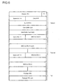
- FIG. 6 illustrates a structure of the frame structure of the HS-DSCH FP in the HSDPA system.
- CmCH-PI Common Channel Priority Indicator
- '0' signifies the lowest priority
- "15" signifies the highest priority.
- the data priority is the main factor in the HSDPA scheduler, the information is only defined in the specific services.
- Services supported by the HSDPA include streaming services such as video on demand (VOD) and Audio on demand (AOD), interactive services such as Web browsing and file downloading, and background services such as e-mail and background data downloading.
- VOD video on demand
- AOD Audio on demand
- interactive services such as Web browsing and file downloading
- background services such as e-mail and background data downloading.
- background services such as e-mail and background data downloading.
- the data priority is defined only for interactive services and background services. This has been true so far, because the related art streaming services are provided by dedicated resources rather than common resources.
- the HSDPA system provides various services with the common resources.
- the service quality of streaming services is not guaranteed simply by the priority information, because data of streaming services are real-time and delay-sensitive. That means there is no need to use the priority information of the data of streaming services.
- real-time data will be lost if the delay of the data exceeds a certain delay limit.
- the scheduler should take traffic characteristics of streaming services into consideration.
- the HSDPA scheduler may be suitable for non-real-time services (i.e. interactive services and background services).
- non-real-time services i.e. interactive services and background services.
- the delay is the most important factor in scheduling Consequently, there is a problem
- the related att scheduler of HSDPA in that is does not take the delay component into account when the supporting services include streaming services.
- the US 6.157.614 describes a wireless ATM network with high quality of service scheduling. It relates to scheduling of ATM flows for supporting multiple services in the upstream direction from the mobile station to the base station.
- the base station includes a scheduler, that regulates the upstream flow of cells by broadcasting grants with permissions to transmit.
- the scheduler includes a virtual framer that provides periodically grants for one or more virtual circuits in response to request receive from terminals. Thus, it can specify which mobile station and which virtual channel within that mobile station can use the grant to transmit one ATM cell.
- An object of the invention is to solve at least the above problems and/or disadvantages and to provide at least the advantages described hereinafter.
- It is another object of the present invention is to provide a packet transmission scheduling method of the HSDPA system suitable for traffic characteristics of each service in a multimedia environment where real-time and non-real-time data coexist, thereby enhancing a service quality.
- It is another object of the present invention is to deliver delay information or priority information of data in the RLC layer to the HSDPA scheduler by using the frame format of the frame protocol, which can contain the related control information.
- the method is performed by the MAC layer and comprises the steps of: receiving real-time data and non-real-time data from the upper layer, receiving buffer status information from the buffer, receiving channel status information from the physical layer, obtaining scheduling control information indicating a data transmission delay or latency of the real-time data and indicating a priority of the non-real-time data, scheduling the data in accordance with the buffer status information, the channel status information, and the scheduling control information, and transmitting the data through the physical layer according to the scheduling to support real-time and non-real-time data services, wherein the data transmission delay or latency occurs within at least one network element or between at least two network elements, and wherein the at least one network element is a RLC layer, a MAC layer, a RNC, or a Node B, and the at least two network elements comprise
- the delay information of data means the delayed period during which the data remains in the MAC layer, or the total delayed period during which the data remains in the MAC layer and the upper layer.
- the delay information in the MAC layer is preferably measured by a timer provided in the MAC layer, and the delay information in the upper layer delay can be measured by an additional timer or by a timer designed for the specific use in the upper layer,
- the delay information in the upper layer is preferably transferred together with data themselves by using a frame protocol on the lub or lur interface.
- the frame protocol uses two frame formats.
- the frame protocol preferably selects one of the two frame formats depending on the type of data to be transmitted. Both headers of the two formats include the data type field to identify the type of data.
- the first frame format of the frame protocol preferably includes the data priority field, and the second frame format preferably includes the delay field. If the data to be transmitted is non-real-time, the frame protocol transmits the data together with priority information by using the first format. If the data is real-time, the frame protocol transmits the data together with the delay information in the upper layer by using the second format.
- the frame format of the frame protocol preferably includes all of the priority field and the delay field.
- the priority field is set, while if the data to be transmitted is real-time, the delay field is set.
- the frame format of the frame protocol preferably includes the priority field, and if the data to be transmitted is real-time, the delay information is converted into the priority information. The closer the data comes to the maximum delay or the more the delay is increased, the higher the priority is set.
- Figure 1 is a drawing showing a structure of the UMTS radio access network (OUTRAN);
- Figure 2 is a drawing showing a protocol structure of the UMTS radio interface
- FIG. 3 is a drawing showing a structure of radio access protocols for the High Speed Downlink Packet Access (HSDPA) system
- Figure 4 is a drawing showing a structure of the MAC layer supporting the HSDPA system
- Figure 5 is a block diagram of the related art HSDPA scheduler in the MAC-hs sublayer
- Figure 6 is a drawing showing a structure of a frame used in the HS-DSCH Frame Protocol.
- FIG. 7 is a block diagram showing a packet scheduler of the HSDPA system in accordance with the preferred embodiment of the present invention.
- the HSDPA system should support both the real-time service and non-real-time service.
- the scheduling method can be based on the related art service that is based on the relative priority of data.
- the delay information of data is preferably taken account in determining the transmission priority.
- a packet transmission scheduling method in the HSDPA system of the preferred embodiment provides a method for increasing the quality of real-time services.
- the data delay of the real-time service signifies the transmission delay of the data between end users or between an end user and a server.
- the delay can occur at diverse parts of transmission paths, such as in the radio interface, UTRAN, core network, or the like.
- the UMTS separates the delay in UTRAN from the delay in the other network elements.
- the transmission delay of real-time data should not exceed a maximum 250 ms between the UE and the SGSN (or MSC).
- the data coming into the cote network from an outside network is delivered to the RNC of the UTRAN through the SGSN or the MSC, and finally transferred to the Node B.
- a transmission buffer is located at the RNC (RLC layer) and the Node B (MAC layer).
- the delay information at the RLC layer or the MAC layer needs to be considered.
- the delay information of the HSDPA scheduler can be divided into two types. One is the delay generated at the RNC, and the other is the delay at the Node B.
- the delay information at the RNC In order for the delay information at the RNC to be used in the HSDPA scheduler, the corresponding data and its related delay information need to be transmitted together to the Node B. That means the delay information is transmitted to the Node B through the lur interface or the lub interface.
- the conventional HS-DSCH FP can be adopted to transmit the data delay information.
- the frame format of the frame protocol since there is no space for delay information in the frame format of the frame protocol, some corrections should be made therefore. An example of the format will be described later.
- a timer is required to measure the delay of data at the RLC layer.
- a new timer is not necessary; rather, the timer used in the related art UMTS can be used.
- the discard timer called Timer_Discard is ready at the RLC layer to measure the lapse of time until each RLC SDU is successfully transmitted after arriving at the RLC layer.
- the value of the discard timer can be used as the delay information at the RLC layer.
- Another delay information that the HSDPA scheduler can use is generated by the Node B itself.
- the delay can be measured by a timer after the data is transmitted to the MAC layer in the Node B.
- Figure 7 is a block diagram showing an operation of the scheduler positioned at the MAC-hs sublayer in accordance with the preferred embodiment of the present invention.
- the MAC-hs sublayer positioned at the Node B receives real-time data from the upper layer and also receives scheduling control information related to the data.
- the scheduling control information can include relative priority information of the data, delay information of the data, the amount of stored data in the upper layer, or the like.
- a control information management unit 209 maintains the scheduling control information received from the upper layer, and determines whether the data has been transmitted based on the transmission information coming from the storage unit (step S210).
- the control information is shared by the scheduler and used as basic scheduling information.
- the data in the MAC-hs sublayer is stored in the storage unit 201, and transmitted according to the decision of the scheduler.
- the storage unit 201 transmits information regarding the buffer status to the scheduler 207 (step S212).
- the status information can include the data priority, the amount of upper layer data, the amount of data in the storage unit, and the delay information of data.
- the timer that measures the elapsed time of data can be located at the storage unit or at the control information management unit. In Figure 7, it is assumed that the timer is located at the storage unit.
- the initial value of the timer can be set to the elapsed time of the data in the upper layer. Since the elapsed time in the upper layer can be stored in the control information management unit 209, it can be transferred using the delay information (step S211). If necessary, the initial value of the timer can be set to 0, which means that only the delay in the storage unit is used for the delay information of data.
- the scheduler 207 receives buffer status information from the storage unit 201 (step S212) and receives channel status information from the physical layer 205 (step S212). Based on the buffer status information from the storage unit 201 and the channel status information from the physical layer 205, the scheduler 207 performs the transmission scheduling of data. The scheduler determines the size of the data block to be transmitted, and selects the MAC-hs SDUs to be contained in the data block. PCI and TSN are also added to the organized data block. Transmission control information is then provided to the storage unit 201 and the HARQ 203, and the data block is then transmitted to the HARQ block 203 and transmitted through the physical layer 205 (steps S214 and S215).
- the HARQ 203 After transmission of the data block, the HARQ 203 provides a transmission result to the storage unit 201 (step S216). If the data block has been successfully transmitted, the storage unit 201 discards the corresponding data (MAC-hs SDUs) from the unit, and also deletes the scheduling control information related to the data from the control information management unit 209, The storage unit 201 then informs the scheduler 208 of the transmission result (step S217) If the data block fails to be transmitted, the HARQ block 203 informs the scheduler 208 of the failure, so that the scheduler can retransmit the data block (S217).
- MAC-hs SDUs MAC-hs SDUs
- the first method is to use the total delay of data-
- the delay of data comes from diverse parts of the network. That is, in order to take into account the delay in the MAC-hs sublayer and the delay in the upper layer (e.g. RLC layer), the delay at the MAC-hs sublayer and the delay in the upper layer ate summed.
- the summed delay of data can be thought as the accurate delay, because all aspects of delay are considered.
- the second method is adopted when the delay of data in the upper layer can be ignored, or when the delay of data at the MAC-hs sublayer is the major portion of the delay. In such a case, because the delay information at the upper layer is not necessary, only the delay in the MAC-hs sublayer is considered.
- the storage unit of the MAC-hs sublayer starts to measure the delay of the corresponding data.
- the delay in the upper layer is delivered together with related data, and added to the delay in the MAC-hs sublayer.
- the total delay of the data is reported to the scheduler.
- the second method conversely, only the delay in the MAC-hs sublayer itself is reported to the scheduler.
- the delay information in the upper layer is transmitted to the MAC-hs sublayer by the HS-DSCH FP as shown in Figure 6. However, since there is no field for transmitting the delay information using the HS-DSCH FP, an additional field is required.
- the value of the delay field can include the actual delay information. However, since the value of the field is to be expressed as a digital value, it is necessary to express the field value in a suitable form. For example, if a delay time is 95.32 ms, the whole and accurate value may not be transmitted. In the Eeld of the FIS-DSCH FP, the delay of 95.32 ms is converted to a suitable digital value based on the time unit such as 1 ms unit or 2 ms. For example, if the reference unit is 1 ms, a value of 95 is set.
- the delay is expressed with the unit of TTI, a basic transmission, time unit used in the HSDPA. The reason is because the scheduler transmits the data in the TTI unit.
- the maximum delay allowed by UMTS is about 250 ms.
- the elapsed time in the upper layer should not exceed this value. Accordingly, if the TTI is 2ms, the maximum value of the field is 125. Thus, with 7 bits, it would be sufficient to provide the delay information.
- the first method uses two independent frame formats for real-time and non-real-time data, respectively.
- delay information is not required for the non-real-time data
- priority information is not needed for the real-time data.
- the same frame format as the related art frame format can be used as it is.
- a field containing the delay information is necessary and the priority information (CmCH-PI) field can be removed.
- an additional indication field is required in the header of the frame format For example, using a '1' can indicate the format for non-real-time data, while a '0' can indicate the format for real-time data.
- the second method uses one frame format for both real-time and non-real-time data.
- the frame format of the current HS-DSCH FP needs to be extended.
- the extended frame format preferably includes a field for delay information.
- some fields in the frame format can be disabled depending on types of data. For example, for the non-real-time data, the delay field is not used, while for the real-time data, the priority filed is not used.
- a field indicating the type of data should be additionally included in the header of the frame format
- the priority means the urgency level of data. Thus, the higher the priority, the faster the data will be transmitted. This means that the scheduler can adjust the transmission delay with the priority. If the delay is properly converted to the priority value, then the real-time service can be supported.
- the upper layer monitors the delay of data to determine the transmission urgency level.
- the upper layer includes the data in the frame format of HS-DSCH FP, it converts the delay into the appropriate priority value and includes it in the priority field of the frame format For example, if the delay of the data reaches the maximum delay limit, the corresponding data is given a high priority.
- the real-time data would have a relatively high priority because the non-real-time traffic is not time-sensitive.
- T_MAX the maximum transmission delay
- T_MAX the delay of the MAC-hs SDU
- the scheduler transmits the emergent data first. That means, the smaller the difference between T_MAX and T_Total (T_MAX-T_Total) is, the faster the data is transmitted. If T_MAX-T_Total is smaller than '0', the corresponding MAC-hs SDUs are discarded because they have no meaning in the real-time service.
- the scheduler transmits the data with the highest priority first. If the value of T_MAX-T_Total becomes smaller than '0', the corresponding data is discarded in the MAC-hs sublayer.
- the maximum transmission delay of data in the HSDPA scheduler is received from the RNC when the service is established. This information can be transmitted through the lur interface or the lub interface.
- RNSAP Radio Network Subsystem Application Part
- NBAP Node B Application Part
- the packet scheduling method for the HSDPA system in accordance with the preferred embodiment has many advantages.
- the HSDPA scheduler in the Node B can support both real-time and non-real-time services with the delay of data and the priority level of data, respectively.
- results can be achieved by using the existing frame format or by implementing a new frame format.
- real-time data can be prioritized over non-real-time data for efficient transmission.
Description
- The present invention relates to a wireless communication system, and more particularly to packet transmission scheduling of the High Speed Downlink Packet Access (HSDPA) system operated in a UMTS terrestrial radio access network (UTRAN).
- The Universal Mobile Telecommunications System (UMTS) is a third generation mobile communication system, which evolved from a Global System for Mobile Communications (GSM) and a European style mobile communication standard. It is intended to provide improved mobile communication services based on a GSM core network (CN) and Wideband Code Division Multiple Access (WCDMA) access technology.
- For the purpose of making a standard for third generation mobile communication systems (IMT-2000 systems) based on GSM core network and WCDMA radio access technology, a group of standard developing organizations, including ETSI of Europe, ARIB/TTC of Japan, T1 of U.S., and TTA of Korea, established the Third Generation Partnership Project (3GPP).
- For the purpose of efficient management and technological development, five Technical Specification Groups (TSGs) were organized under the 3GPP in consideration of network construction factors and their operations.
- Each TSG is responsible for approving, developing, and managing specifications related to a pertinent area. Among them, the Radio Access Network (RAN) group has developed Functions, requirements, and interface specifications related to UE and UMTS terrestrial radio access network (UTRAN) in order to establish a new radio access network specification to the third generation mobile communication system.
- The TSG-RAN group consists of one plenary group and four working groups. Working Group 1 (WG1) has been developing specifications for a physical layer (Layer 1) and WG2 has been specifying functions of a data link layer (Layer 2) between UE and UTRAN. In addition, WG3 has been developing specifications for interfaces among Node Bs (the Node B is a kind of base station in the wireless communications), Radio Network Controllers (RNCs), and the core network. Lastly, WG4 has been discussing requirements for radio link performance and radio resource management.
- Figure 1 illustrates a structure of the UTRAN defined in 3GPP. As shown in Figure 1, the UTRAN 110 includes at least one radio network sub-systems (RNSs) 120 and 130, Each
RNS RNC more Node Bs B 122 is managed by RNC 121, and receives information transmitted from the physical layer of the UE 150 through an uplink channel and transmits a data to the UE 150 through a downlink channel. - Accordingly, the Node B acts as an access point of the UTRAN from the UE point of view.
- The
RNCs core network 140 depending on types of services provided to users. - For example, the
RNCs - The RNC in charge of a direct management of the Node B is called a Control RNC (CRNC). The CRNC manages common radio resources.
- On the other hand, the RNC that manages dedicated radio resources for a specific UE is called a Serving RNC (SRNC). The CRNC and the SRNC can be co-located in the same physical node. However, if the UE has been moved to an area of a new RNC that is different from SRNC, the CRNC and the SRNC may be located at physically different places.
- There is an interface that can operate as a communication path between various network elements. The interface between a Node B and a RNC is called a lub interface, and an interface between RNCs is called a lur interface. And an interface between the RNC and the core network is called a lu interface.
- Figure 2 illustrates a protocol structure of a radio interface protocol defined in the 3GPP. As shown in Figure 2, the radio interface protocol horizontally includes a physical layer, a data link layer, and a network layer, and is vertically divided into a control plane for transmission of control information (signaling) and a user plane for transmission of data information.
- The user plane is a region through which user traffic such as voice information or IP (Internet Protocol) packets is transmitted, and the control plane is a region through which control information required for network maintenance and management is transmitted.
- Of the layets, the physical layer (PHY) handles transmission of data using a wireless physical channel between the UE and the UTRAN. The typical functions of the physical layer include data multiplexing, channel coding, spreading, and modulation.
- The physical layer exchanges information with a Medium Access Control (MAC) layer through a transport channel. The transport channel is classified into a dedicated transport channel and a common transport channel depending on whether its use is dedicated to one UE or whether it is shared among several UEs.
- The MAC layer transmits data by using a suitable mapping between logical channels and transport channels The MAC layer is internally divided into two sub-layers, to wit a MAC-d sub-layer which manages the dedicated transport channel, and a MAC-c/sh sub-layer which manages the common transport channel. The MAC-d sub-layer is located in the SRNC and the MAC-c/sh sub-layer is located in the CRNC.
- There are various kinds of logical channels according to what kind of information the channel carries. The logical channel can be divided into two channels. One logical channel is a control channel for transmission of the control plane information and the other is a traffic channel for transmission of the user plane information.
- The radio link control (RLC) layer is responsible for reliable transmission of RLC protocol data units (PDUs). The RLC may segment or concatenate RLC service data units (SDUs) delivered from the higher layer. If the RLC PDUs are ready, they are delivered to the MAC and transmitted sequentially to the other node (UE or UTRAN). Sometimes, the RLC PDU can be lost during the transmission. In this case, the lost PDU can be retransmitted. The retransmission function of the RLC layer is called an Automatic Repeat reQuest (ARQ).
- The RLC layer may include several RLC entities. Each of them performs an independent radio link control function. The operation mode of each RLC entity is one of transparent mode (TM), an unacknowledged mode (UM), and an acknowledged mode (AM) depending on the adopted functions.
- The Packet Data Convergence Protocol (PDCP) layer is positioned over the RLC layer and efficiently transmits data of network protocols such as IPv4 or IPv6. For example, a header compression method in which header information of a packet is reduced can be used. The PDCP layer may include several independent PDCP entities like the RLC layer. The Broadcast/Multicast Control (BMC) layer is responsible for transmitting broadcast messages from a Cell Broadcast Center (CBS) positioned at a core network. The primary function of BMC is to schedule and transmit cell broadcast messages destined for a UE. The BMC layer, in general, uses an RLC entity operated in the unacknowledged mode in order to transmit broadcast messages.
- Finally, the Radio Resource Control (RRC) layer is a layer defined in the control plane. The RRC performs functions of establishment, re-establishment, and release of radio resources. In addition, the RRC layer can exchange control information between UE and UTRAN using RRC messages.
- The maximum transmission rate of UMTS is 2 Mbps in the indoor and pico-cell environment, and 384 Kbps in the outdoor environment. However, as wireless Internet services have become popular, various services require higher data rates and higher capacity. Although UMTS has been designed to support multimedia wireless services, the maximum data rate of 2Mbps is not enough to satisfy the requited quality of services. Therefore, the 3GPP is conducting research directed to providing an enhanced data rate and radio capacity. One result of the research is the High Speed Downlink Packet Access (HSDPA). The purpose of the HSDPA system is to provide a maximum data rate of 10 Mbps and to improve the radio capacity in the downlink.
- Various techniques in the HSDPA system include Link Adaptation (LA) and Hybrid Automatic Repeat reQuest (HARQ).
- In the LA method, the UTRAN can choose the appropriate modulation and coding scheme (MCS) according to the channel condition. For example, if the channel condition is good, LA uses 16 Quadrature Amplitude Modulation (QAM) to increase the throughput. If a channel condition is not as good, however, LA uses Quadrature Phase Shift Keying (QPSK) to increase the probability of success.
- The HARQ method retransmits lost packets, but the exact operation is different than the retransmission method in the RLC layer. If one packet is corrupted during transmission, HARQ transmits another packet that contains the additional information for recovery. The retransmitted packet and the original packer are combined in the receiver. The retransmitted packet may contain the same information as that of the previously transmitted data, or may contain any additional supplementary information for data recovery.
- Since the HSDPA system is an evolutional form of the UMTS system, the conventional UMTS network needs to be maintained as much as possible to support backward compatibility and to reduce the cost of network deployment. However, some minor changes are inevitable.
- To reduce the impact of the changes, most of the features are supported in Node B. This means that other parts of the UMTS network will not be affected. Accordingly, some functions in Node B need to be changed and some MAC functions are transferred from RNC. The MAC functionalities constitute a new MAC sublayer in Node B and it is called ''MAC-hs" sublayer.
- The MAC-hs sublayer is placed above the physical layer, and performs packet scheduling and various other functions (including HARQ and LA) In addition, the MAC-hs sublayer manages a transport channel called an HSDPA - Downlink Shared Channel (HS-DSCH), which is used to deliver data from the MAC-hs sublayer to the physical layer.
- Figure 3 shows a structure of a radio interface protocol for the HSDPA system. As shown in Figure 3, the MAC-hs sublayer is placed over the physical layer (PHY) in the Node B. In both the UE and UTRAN, the MAC-hs sublayer transfers data to the upper layer through MAC-c/sh and MAC-d sublayers. The MAC-c/sh and the MAC-d sublayers are located in the CRNC and the SRNC, respectively, as in the related art system. In Figure 3, an HS-DSCH Frame Protocol (FP) delivers the HSDPA data on the lub or the lur interface.
- Figure 4 illustrates the structure of the MAC layer in the HSDPA system. As shown in Figure 4, the MAC layer is divided into a MAC-
d sublayer 161, a MAC-c/shsublayer 162, and a MAC-hs sublayer 163. The MAC-d sublayer 161 is in the SRNC and manages dedicated logical channels. The MAC-c/shsublayer 162 is located in the CRNC and manages a common transport channel The MAC-hs sublayer 163 is located in the Node B and manages the HS-DSCH. - In the HSDPA system, the MAC-c/sh
sublayer 162 controls the data flow between the MAC-d sublayer 161 and the MAC-hs sublayer 163. The flow control function is used to prevent data from being discarded during network congestion, and to reduce the time delay of signaling signals. The flow control can be performed independently according to a priority of data transmitted through each HS-DSCH. - The HARQ function, as stated previously, improves the efficiency of data transmission. In the Node B, the MAC-
hs sublayer 163 contains one HARQ block that supports the HARQ function. The HARQ block includes several HARQ entities for controlling a HARQ operation of each UE. There is one HARQ entity for each UE in the HARQ block. - Moreover, there are several HARQ processes inside each HARQ entity. Each HARQ process is used for transmission of the data block," which is composed of one or more MAC MAC-hs SDUs. The data block is processed one by one in the HARQ process.
- If the specific data block is successfully transmitted, the HARQ process can treat another data block. If the transmission fails, the HARQ process retransmits the data block until the data block is either successfully transmitted or discarded. The number of MAC-hs SDUs constituting the data block differs depending on the status of the radio channel. If the channel is in a good condition, it can transmit mote MAC-hs SDUs. Conversely, if the channel is in a bad condition, it can transmit fewer MAC-hs SDUs, and therefore a relatively small number of MAC-hs SDUs comprises a data block.
- The scheduling block determines the size of the data block based on the information (channel condition) from the physical layer. Each data block can be transmitted in the unit of Transmission Time Interval (TTI) which is 2 ms in the HSDPA system. In addition, the scheduling function of the Node B determines the order of the data transmission according to the priorities of data. The scheduling block adds a priority class identifier (PCI) and a transmission sequence number (TSN) to the data block and delivers it to a suitable HARQ process. If the transmission of the data block is not successful, the identical data block is retransmitted.
- The TFC selection function selects the appropriate transport format of each HS-DSCH when several HS-DSCHs are used for the data transmission. The transmission procedure in tThe transmission procedure in tribed with reference to Figure 4.
- The channel switching block in the MAC-d layer determines the transmission path of the RLC PDU, which is transferred through a Dedicated Traffic Channel (DTCH) or a Dedicated Control Channel (DCCH) from the RLC layer. If the RLC PDU is going to be transmitted to the Dedicated channel (DCH), a header field is added into the PDU and it is transmitted to the physical layer through the DCH. If the HS-DSCH channel is used, the RLC PDU is transmitted to the MAC-c/sh
sublayer 162 through a transmission, channel multiplexer (T/C MUX). The T/C MUX adds identification information into the header of the PDU in order to identify the logical channel to which each data belongs. - Upon receiving the RLC PDU, the MAC-c/sh
sublayer 162 transfers the packet to the MAC-hs sublayer 163. Subsequently, the data transmitted to the MAC-hs sublayer is stored in a buffer of the MAC-hs sublayer 163 and constructed as a data block with a suitable size. The scheduling function determines the size of the data block based on the channel condition. Next, the PCI and TSN are added to the data block, and it is delivered to the HARQ process by the scheduling function. - Figure 5 illustrates an operation of the scheduling block of the MAC-hs sublayer in Node B. As shown in Figure 5, the
HSDPA scheduler 174 receives information regarding a data priority and an amount of stored data from astorage unit 171, and receives channel status information from the physical layer 173 (S101, S102). - The
storage unit 171 is preferably a soft memory in which data can be easily erased and written, and stores the MAC-hs SDUs delivered from an upper layer. - The
scheduler 174 controls the operations of thestorage unit 171 and theHARQ entity 172 based on the information (steps S103, S104). Thescheduler 174 determines the size of the data block, and constitutes the data block, and addes PCI and TSN fields in the data block. Next, thescheduler 174 transmits the corresponding data block to a suitable HARQ process in the HARQ entity, where the data block will be transmitted through the physical layer. - If the data block is successfully transmitted, the corresponding data in the
storage unit 171 is deleted based on the feedback information (step S105). At the same time, the HARQ block reports to the scheduler whether or not the data block has been successfully transmitted. Using the transmission result, thescheduler 174 can adjust the transmission of data blocks (step S106). - In general, overall system efficiency and capacity can be determined by an adopted scheduling algorithm. Therefore, the scheduling algorithm should be suitable for characteristics of the provided service.
- A scheduling algorithm used in the HSDPA system is currently based on the priority information of each data. The scheduler monitors data in the storage unit of the MAC-hs sublayer, and transmits the data block having the higher priority.
- The priority information of each data (MAC-hs SDU) is transferred through a HS-DSCH FP (Frame Protocol) between the Node B and the RNC.
- Figure 6 illustrates a structure of the frame structure of the HS-DSCH FP in the HSDPA system. Referring to Figure 6, CmCH-PI (Common Channel Priority Indicator) field indicates a priority of the MAC-hs SDUs included in the corresponding data frame, and has values of 0-15. '0' signifies the lowest priority, while "15" signifies the highest priority.
- 'Even though the data priority is the main factor in the HSDPA scheduler, the information is only defined in the specific services. Services supported by the HSDPA include streaming services such as video on demand (VOD) and Audio on demand (AOD), interactive services such as Web browsing and file downloading, and background services such as e-mail and background data downloading. Among these services, the data priority is defined only for interactive services and background services. This has been true so far, because the related art streaming services are provided by dedicated resources rather than common resources. However, the HSDPA system provides various services with the common resources.
- Additionally, unlike other types of services, the service quality of streaming services is not guaranteed simply by the priority information, because data of streaming services are real-time and delay-sensitive. That means there is no need to use the priority information of the data of streaming services.
- Typically, real-time data will be lost if the delay of the data exceeds a certain delay limit. In order to reduce the loss of real-time data, the scheduler should take traffic characteristics of streaming services into consideration.
- Because the current HSDPA scheduler operates based on the priorities of packets, the HSDPA scheduler may be suitable for non-real-time services (i.e. interactive services and background services). For real-time services, however, the delay is the most important factor in scheduling Consequently, there is a problem With the related att scheduler of HSDPA in that is does not take the delay component into account when the supporting services include streaming services.
- The US 6.157.614 describes a wireless ATM network with high quality of service scheduling. It relates to scheduling of ATM flows for supporting multiple services in the upstream direction from the mobile station to the base station. The base station includes a scheduler, that regulates the upstream flow of cells by broadcasting grants with permissions to transmit. Namely, the scheduler includes a virtual framer that provides periodically grants for one or more virtual circuits in response to request receive from terminals. Thus, it can specify which mobile station and which virtual channel within that mobile station can use the grant to transmit one ATM cell.
- An object of the invention is to solve at least the above problems and/or disadvantages and to provide at least the advantages described hereinafter.
- It is another object of the present invention is to provide a packet transmission scheduling method of the HSDPA system suitable for traffic characteristics of each service in a multimedia environment where real-time and non-real-time data coexist, thereby enhancing a service quality.
- It is another object of the present invention to provide a packet transmission scheduling method of the HSDPA system based on both delay information as well as data priorities in the Node B where real-time and non-real-time data coexist.
- It is another object of the present invention to provide a packet transmission scheduling method of the HSDPA system that considers the delay information in the RLC layer and the delay in the MAC layer for real-time services.
- It is another object of the present invention is to deliver delay information or priority information of data in the RLC layer to the HSDPA scheduler by using the frame format of the frame protocol, which can contain the related control information.
- To achieve at least the above objects in whole or in parts, there is provided method of transmitting data in a mobile communications system having a radio interface protocol with an upper layer, a MAC layer including a buffer, and a physical layer, the method is performed by the MAC layer and comprises the steps of: receiving real-time data and non-real-time data from the upper layer, receiving buffer status information from the buffer, receiving channel status information from the physical layer, obtaining scheduling control information indicating a data transmission delay or latency of the real-time data and indicating a priority of the non-real-time data, scheduling the data in accordance with the buffer status information, the channel status information, and the scheduling control information, and transmitting the data through the physical layer according to the scheduling to support real-time and non-real-time data services, wherein the data transmission delay or latency occurs within at least one network element or between at least two network elements, and wherein the at least one network element is a RLC layer, a MAC layer, a RNC, or a Node B, and the at least two network elements comprise a RNC and a Node B or comprise a RLC layer and a MAC layer.
- In the data transmission method of the HSDPA system of the preferred ernbodiment, the delay information of data means the delayed period during which the data remains in the MAC layer, or the total delayed period during which the data remains in the MAC layer and the upper layer. Also the delay information in the MAC layer is preferably measured by a timer provided in the MAC layer, and the delay information in the upper layer delay can be measured by an additional timer or by a timer designed for the specific use in the upper layer, Moreover, the delay information in the upper layer is preferably transferred together with data themselves by using a frame protocol on the lub or lur interface.
- In a first embodiment of the present invention, the frame protocol uses two frame formats. The frame protocol preferably selects one of the two frame formats depending on the type of data to be transmitted. Both headers of the two formats include the data type field to identify the type of data. The first frame format of the frame protocol preferably includes the data priority field, and the second frame format preferably includes the delay field. If the data to be transmitted is non-real-time, the frame protocol transmits the data together with priority information by using the first format. If the data is real-time, the frame protocol transmits the data together with the delay information in the upper layer by using the second format.
- In a second embodiment of the present invention, the frame format of the frame protocol preferably includes all of the priority field and the delay field. Thus, if the data to be transmitted is non-real-time, the priority field is set, while if the data to be transmitted is real-time, the delay field is set.
- In a third embodiment of the present invention, the frame format of the frame protocol preferably includes the priority field, and if the data to be transmitted is real-time, the delay information is converted into the priority information. The closer the data comes to the maximum delay or the more the delay is increased, the higher the priority is set.
- Additional advantages, objects, and features of the invention will be set forth in part in the description which follows and in part will become apparent to those having ordinary skill in the art upon examination of the following or may be learned from practice of the invention. The objects and advantages of the invention may be realized and attained as particularly pointed out in the appended claims.
- The invention will be described in derail with reference to the following drawings in which like reference numerals refer to like elements wherein:
- Figure 1 is a drawing showing a structure of the UMTS radio access network (OUTRAN);
- Figure 2 is a drawing showing a protocol structure of the UMTS radio interface;
- Figure 3 is a drawing showing a structure of radio access protocols for the High Speed Downlink Packet Access (HSDPA) system;
- Figure 4 is a drawing showing a structure of the MAC layer supporting the HSDPA system;
- Figure 5 is a block diagram of the related art HSDPA scheduler in the MAC-hs sublayer;
- Figure 6 is a drawing showing a structure of a frame used in the HS-DSCH Frame Protocol; and
- Figure 7 is a block diagram showing a packet scheduler of the HSDPA system in accordance with the preferred embodiment of the present invention.
- The HSDPA system should support both the real-time service and non-real-time service. For non-real-time service, the scheduling method can be based on the related art service that is based on the relative priority of data. However, for real-time service, the delay information of data is preferably taken account in determining the transmission priority.
- A packet transmission scheduling method in the HSDPA system of the preferred embodiment provides a method for increasing the quality of real-time services.
- In general, the data delay of the real-time service signifies the transmission delay of the data between end users or between an end user and a server. The delay can occur at diverse parts of transmission paths, such as in the radio interface, UTRAN, core network, or the like.
- Every delay that occurs in the various parts should be taken into account, but it is not easy to consider the diversity of the delay in all of the regions in the network. Thus, the UMTS separates the delay in UTRAN from the delay in the other network elements. For example, the transmission delay of real-time data should not exceed a maximum 250 ms between the UE and the SGSN (or MSC).
- As for the transmission path in the HSDPA system, the data coming into the cote network from an outside network is delivered to the RNC of the UTRAN through the SGSN or the MSC, and finally transferred to the Node B. In the UTRAN, a transmission buffer is located at the RNC (RLC layer) and the Node B (MAC layer). In order to consider the delay of the real-time data, the delay information at the RLC layer or the MAC layer needs to be considered.
- In particular, since the HSDPA scheduler in the Node B substantially handles the data transmission, the scheduler needs to use the delay information for transmission. The delay information of the HSDPA scheduler can be divided into two types. One is the delay generated at the RNC, and the other is the delay at the Node B.
- First, let us consider the delay in the RLC layer. In order for the delay information at the RNC to be used in the HSDPA scheduler, the corresponding data and its related delay information need to be transmitted together to the Node B. That means the delay information is transmitted to the Node B through the lur interface or the lub interface.
- If the HSDPA system supports real-time services, the conventional HS-DSCH FP can be adopted to transmit the data delay information. However, since there is no space for delay information in the frame format of the frame protocol, some corrections should be made therefore. An example of the format will be described later.
- On the other hand, a timer is required to measure the delay of data at the RLC layer. However, a new timer is not necessary; rather, the timer used in the related art UMTS can be used. For example, the discard timer called Timer_Discard is ready at the RLC layer to measure the lapse of time until each RLC SDU is successfully transmitted after arriving at the RLC layer. The value of the discard timer can be used as the delay information at the RLC layer.
- Next, another delay information that the HSDPA scheduler can use is generated by the Node B itself. The delay can be measured by a timer after the data is transmitted to the MAC layer in the Node B.
- Figure 7 is a block diagram showing an operation of the scheduler positioned at the MAC-hs sublayer in accordance with the preferred embodiment of the present invention. Referring to Figure 7, the MAC-hs sublayer positioned at the Node B receives real-time data from the upper layer and also receives scheduling control information related to the data. The scheduling control information can include relative priority information of the data, delay information of the data, the amount of stored data in the upper layer, or the like.
- A control
information management unit 209 maintains the scheduling control information received from the upper layer, and determines whether the data has been transmitted based on the transmission information coming from the storage unit (step S210). The control information is shared by the scheduler and used as basic scheduling information. - The data in the MAC-hs sublayer is stored in the
storage unit 201, and transmitted according to the decision of the scheduler. Thestorage unit 201 transmits information regarding the buffer status to the scheduler 207 (step S212). The status information can include the data priority, the amount of upper layer data, the amount of data in the storage unit, and the delay information of data. - The timer that measures the elapsed time of data can be located at the storage unit or at the control information management unit. In Figure 7, it is assumed that the timer is located at the storage unit. The initial value of the timer can be set to the elapsed time of the data in the upper layer. Since the elapsed time in the upper layer can be stored in the control
information management unit 209, it can be transferred using the delay information (step S211). If necessary, the initial value of the timer can be set to 0, which means that only the delay in the storage unit is used for the delay information of data. - Next, the
scheduler 207 receives buffer status information from the storage unit 201 (step S212) and receives channel status information from the physical layer 205 (step S212). Based on the buffer status information from thestorage unit 201 and the channel status information from thephysical layer 205, thescheduler 207 performs the transmission scheduling of data. The scheduler determines the size of the data block to be transmitted, and selects the MAC-hs SDUs to be contained in the data block. PCI and TSN are also added to the organized data block. Transmission control information is then provided to thestorage unit 201 and theHARQ 203, and the data block is then transmitted to theHARQ block 203 and transmitted through the physical layer 205 (steps S214 and S215). - After transmission of the data block, the
HARQ 203 provides a transmission result to the storage unit 201 (step S216). If the data block has been successfully transmitted, thestorage unit 201 discards the corresponding data (MAC-hs SDUs) from the unit, and also deletes the scheduling control information related to the data from the controlinformation management unit 209, Thestorage unit 201 then informs the scheduler 208 of the transmission result (step S217) If the data block fails to be transmitted, theHARQ block 203 informs the scheduler 208 of the failure, so that the scheduler can retransmit the data block (S217). - There are two methods for managing the delay information of data.
- The first method is to use the total delay of data- In this method, the delay of data comes from diverse parts of the network. That is, in order to take into account the delay in the MAC-hs sublayer and the delay in the upper layer (e.g. RLC layer), the delay at the MAC-hs sublayer and the delay in the upper layer ate summed. The summed delay of data can be thought as the accurate delay, because all aspects of delay are considered.
- The second method is adopted when the delay of data in the upper layer can be ignored, or when the delay of data at the MAC-hs sublayer is the major portion of the delay. In such a case, because the delay information at the upper layer is not necessary, only the delay in the MAC-hs sublayer is considered.
- In both the methods, when the MAC-hs SDU is received from the upper layer, the storage unit of the MAC-hs sublayer starts to measure the delay of the corresponding data. In the first method, the delay in the upper layer is delivered together with related data, and added to the delay in the MAC-hs sublayer. The total delay of the data is reported to the scheduler. In the second method, conversely, only the delay in the MAC-hs sublayer itself is reported to the scheduler.
- Referring to the first method, since the delay information in the upper layer is transmitted through the lur or the lub interface, a new system standard is required between heterogeneous systems. Solutions for this will now be described.
- The delay information in the upper layer is transmitted to the MAC-hs sublayer by the HS-DSCH FP as shown in Figure 6. However, since there is no field for transmitting the delay information using the HS-DSCH FP, an additional field is required.
- The value of the delay field can include the actual delay information. However, since the value of the field is to be expressed as a digital value, it is necessary to express the field value in a suitable form. For example, if a delay time is 95.32 ms, the whole and accurate value may not be transmitted. In the Eeld of the FIS-DSCH FP, the delay of 95.32 ms is converted to a suitable digital value based on the time unit such as 1 ms unit or 2 ms. For example, if the reference unit is 1 ms, a value of 95 is set.
- In the preferred embodiment, the delay is expressed with the unit of TTI, a basic transmission, time unit used in the HSDPA. The reason is because the scheduler transmits the data in the TTI unit.
- In general, the maximum delay allowed by UMTS is about 250 ms. The elapsed time in the upper layer should not exceed this value. Accordingly, if the TTI is 2ms, the maximum value of the field is 125. Thus, with 7 bits, it would be sufficient to provide the delay information.
- Consequently, because the new field of the frame format is required to express the delay of data, a new and different frame format structure needs to be used. Two solutions are proposed hereinbelow.
- The first method uses two independent frame formats for real-time and non-real-time data, respectively, In general, delay information is not required for the non-real-time data, while priority information is not needed for the real-time data. Thus, for non-real-time data, the same frame format as the related art frame format can be used as it is. However, for teal-time data, a field containing the delay information is necessary and the priority information (CmCH-PI) field can be removed. In addition, in order to differentiate the two frame formats, an additional indication field is required in the header of the frame format For example, using a '1' can indicate the format for non-real-time data, while a '0' can indicate the format for real-time data.
- The second method uses one frame format for both real-time and non-real-time data. For this purpose, the frame format of the current HS-DSCH FP needs to be extended. The extended frame format preferably includes a field for delay information. In this method, some fields in the frame format can be disabled depending on types of data. For example, for the non-real-time data, the delay field is not used, while for the real-time data, the priority filed is not used. In order to recognize the field being used, a field indicating the type of data should be additionally included in the header of the frame format
- In the above description diverse methods for transmitting the delay information via the network interface have been discussed. However, some service providers are not willing to change the current system. Consequently, the current frame format should support the real-time and non-real time data. But, as described before, there is currently no field for delay information.
- One way to overcome this problem is to convert the delay information into the priority information. The priority means the urgency level of data. Thus, the higher the priority, the faster the data will be transmitted. This means that the scheduler can adjust the transmission delay with the priority. If the delay is properly converted to the priority value, then the real-time service can be supported.
- Thus, the upper layer monitors the delay of data to determine the transmission urgency level. When the upper layer includes the data in the frame format of HS-DSCH FP, it converts the delay into the appropriate priority value and includes it in the priority field of the frame format For example, if the delay of the data reaches the maximum delay limit, the corresponding data is given a high priority. Generally speaking, the real-time data would have a relatively high priority because the non-real-time traffic is not time-sensitive.
- Finally, the scheduler in the MAC-hs sublayer should be aware of the maximum transmission delay (T_MAX) for each real-time service. Assume that the delay of the MAC-hs SDU (T_Total) means the total delay of the data in the UTRAN. If the delay in the upper layer is considered, T_Total corresponds to the sum of the delay in the upper layer T_RLC and the delay in the MAC layer T_MAC (T_Total =T_RLC+T_MAC). If the delay is only in the MAC-hs sublayer, T_Total = T_MAC.
- Accordingly, the scheduler transmits the emergent data first. That means, the smaller the difference between T_MAX and T_Total (T_MAX-T_Total) is, the faster the data is transmitted. If T_MAX-T_Total is smaller than '0', the corresponding MAC-hs SDUs are discarded because they have no meaning in the real-time service.
- If the delay of the data in the upper layer is converted into the priority, the scheduler transmits the data with the highest priority first. If the value of T_MAX-T_Total becomes smaller than '0', the corresponding data is discarded in the MAC-hs sublayer.
- The maximum transmission delay of data in the HSDPA scheduler is received from the RNC when the service is established. This information can be transmitted through the lur interface or the lub interface. In particular, the Radio Network Subsystem Application Part (RNSAP) protocol defined in the Iur interface of UMTS or Node B Application Part (NBAP) protocol defined in the Iub interface of UMTS can be used.
- The packet scheduling method for the HSDPA system in accordance with the preferred embodiment has many advantages.
- For example, the HSDPA scheduler in the Node B can support both real-time and non-real-time services with the delay of data and the priority level of data, respectively.
- Additionally, the results can be achieved by using the existing frame format or by implementing a new frame format.
- Moreover, real-time data can be prioritized over non-real-time data for efficient transmission.
- The foregoing embodiments and advantages are merely exemplary and are not to be construed as limiting the present invention. The present teaching can be readily applied to other types of apparatuses. The description of the present invention is intended to be illustrative, and not to limit the scope of the claims. Many alternatives, modifications, and variations will be apparent to those skilled in the art. In the claims, means-plus-function clauses are intended to cover the structures described herein as performing the recited function and not only structural equivalents but also equivalent structures
Claims (16)
- A method of transmitting data in a mobile communications system having a radio interface protocol with an upper layer, a MAC layer including a buffer (201), and a physical layer (205), the method is performed by the MAC layer, the method comprises the step of:- receiving real-time data and non-real-time data from the upper layer;characterized by- receiving (S212) buffer status information from the buffer (201);- receiving (S213) channel status information from the physical layer (205);- obtaining (S211) scheduling control information indicating a data transmission delay or latency of the real-time data and indicating a priority of the non-real-time data;- scheduling (S214) the data in accordance with the buffer status information, the channel status information, and the scheduling control information; and- transmitting (S215) the data through the physical layer according to the scheduling to support real-time and non-real-time data services,- wherein the data transmission delay or latency occurs within at least one network element or between at least two network elements, and- wherein the at least one network element is a RLC layer, a MAC layer, a RNC (121, 131), or a Node B (122, 133), and the at least two network elements comprise a RNC (121, 131) and a Node B (122, 133) or comprise a RLC layer and a MAC layer.
- The method of claim 1, wherein the steps are implemented to allow backward compatibility of UMTS networks.
- The method of claim 1, wherein the steps are implemented for a High Speed Downlink Packet Access system.
- The method of claim 1. wherein the steps are implemented for a network protocol based upon IPv4 or IPv6.
- The method of claim 1, wherein the steps are implemented to support a wireless Internet service access technology.
- The method of claim 1, wherein the information indicating the data transmission delay or latency is transmitted over a radio interface by using a frame protocol having a first frame format for real-time data and a second frame format for non-real-time data, or by using a frame protocol having a single frame format with at least one field therein being disabled to distinguish between real-time data and non-real-time data.
- The method of claim 1, wherein the information indicating the data transmission delay or latency is transmitted over a radio interface by using a frame protocol in which the delay or latency information is converted into priority information such that data packets related to the real-time data service have higher priority than the data packets related to the non-real-time data service.
- A mobile communications system having a radio interface protocol with an upper layer, a MAC layer, and a physical layer, the MAC layer is characterized by:- a buffer (201) adapted to receive real-time data and non-real-time data from the upper layer;- a control information manager (209) adapted to obtain scheduling control information indicating a data transmission delay or latency of the real-time data and indicating a priority of the non-real-time data :- a scheduler (207) adapted to receive buffer status information from the buffer (201), to receive channel status information from the physical layer (205), to obtain the scheduling control information from the control information manager (209) and to schedule the data in accordance with the buffer status information, the channel status information, and the scheduling control information; and- a transmitter (203) adapted to transmit the data through the physical layer (205) according to the scheduling of the scheduler (207) to support real-time and non-real-time data services ,- wherein the data transmission delay or latency occurs within at least one network element or between at least two network elements, and- wherein the at least one network element is a RLC layer, a MAC layer, a RNC (121, 131), or a Node B (122, 133), and the at least two network elements comprise a RNC (121, 131) and a Node B (122, 133) or comprise a RLC layer and a MAC layer.
- The apparatus of claim 8, wherein the elements are implemented to allow backward compatibility of UMTS networks.
- The apparatus of claim 8, wherein the elements are implemented for a High Speed Downlink Packet Access system.
- The apparatus of claim 8, wherein the elements are implemented for a network protocol based upon IPv4 or IPv6.
- The apparatus of claim 8, wherein the elements are implemented to support a wireless Internet service access technology.
- The apparatus of claim 8, wherein a data transmission delay or latency at the Node B (122. 133) is obtained by using a timer that measures a time between an arrival of the data at the Node B and until the data is successfully transmitted from the Node B (122, 133).
- The apparatus of claim 8, wherein a data transmission delay or latency at the RLC layer is obtained by using a discard timer that measures a time between an arrival of the data at the RLC layer and until the data is successfully transmitted from the RLC layer.
- The apparatus of claim 8, wherein the information indicating the delay or latency is transmitted by the scheduler (207) over a radio interface by using a frame protocol having a first frame format for real-time data and a second frame format for non-real-time data, or by using a frame protocol having a single frame format with at least one field therein being disabled to distinguish between real-time data and non-real-time data.
- The apparatus of claim 8, wherein the information indicating the delay or latency is transmitted by the scheduler (207) over a radio interface by using a frame protocol in which the delay or latency information is converted into priority information such that data related to the real-time data service have higher priority than the data related to the non-real-time data service.
Applications Claiming Priority (4)
| Application Number | Priority Date | Filing Date | Title |
|---|---|---|---|
| KR2001073641 | 2001-11-24 | ||
| KR1020010073641A KR20030042846A (en) | 2001-11-24 | 2001-11-24 | Packet Scheduling method for High Speed Data Packet Access system |
| KR2002000631 | 2002-01-05 | ||
| KR1020020000631A KR100774478B1 (en) | 2002-01-05 | 2002-01-05 | A Method for transmitting a packet data in the High Speed Downlink Packet Access system |
Publications (3)
| Publication Number | Publication Date |
|---|---|
| EP1318632A2 EP1318632A2 (en) | 2003-06-11 |
| EP1318632A3 EP1318632A3 (en) | 2004-01-14 |
| EP1318632B1 true EP1318632B1 (en) | 2007-01-03 |
Family
ID=26639482
Family Applications (1)
| Application Number | Title | Priority Date | Filing Date |
|---|---|---|---|
| EP02026087A Revoked EP1318632B1 (en) | 2001-11-24 | 2002-11-22 | Packet data transmission scheduling technique |
Country Status (3)
| Country | Link |
|---|---|
| US (7) | US7515616B2 (en) |
| EP (1) | EP1318632B1 (en) |
| CN (1) | CN1233180C (en) |
Cited By (14)
| Publication number | Priority date | Publication date | Assignee | Title |
|---|---|---|---|---|
| US8107456B2 (en) | 2007-06-18 | 2012-01-31 | Lg Electronics Inc. | Method of performing uplink synchronization in wireless communication system |
| US8184576B2 (en) | 2007-04-30 | 2012-05-22 | Lg Electronics Inc. | Method for state transition of mobile terminal |
| US8184570B2 (en) | 2007-04-30 | 2012-05-22 | Lg Electronics Inc. | Method of transmitting data in wireless communication system supporting multimedia broadcast/multicast service |
| US8218524B2 (en) | 2007-04-30 | 2012-07-10 | Lg Electronics Inc. | Method for transmitting or receiving data unit using header field existence indicator |
| US8229517B2 (en) | 2007-05-01 | 2012-07-24 | Lg Electronics Inc. | Data transmission/reception method |
| US8428013B2 (en) | 2006-10-30 | 2013-04-23 | Lg Electronics Inc. | Method of performing random access in a wireless communcation system |
| US8463300B2 (en) | 2007-06-18 | 2013-06-11 | Lg Electronics Inc. | Paging information transmission method for effective call setup |
| US8543089B2 (en) | 2007-04-30 | 2013-09-24 | Lg Electronics Inc. | Method for performing an authentication of entities during establishment of wireless call connection |
| US8576741B2 (en) | 2006-10-30 | 2013-11-05 | Lg Electronics Inc. | Method for transitioning between multiple reception levels |
| US8619685B2 (en) | 2006-10-02 | 2013-12-31 | Lg Electronics Inc. | Method for transmitting and receiving paging message in wireless communication system |
| US8798070B2 (en) | 2007-05-02 | 2014-08-05 | Lg Electronics Inc. | Method of transmitting data in a wireless communication system |
| US8811336B2 (en) | 2006-08-22 | 2014-08-19 | Lg Electronics Inc. | Method of performing handover and controlling thereof in a mobile communication system |
| USRE45347E1 (en) | 2007-04-30 | 2015-01-20 | Lg Electronics Inc. | Methods of transmitting data blocks in wireless communication system |
| US8964652B2 (en) | 2007-06-18 | 2015-02-24 | Lg Electronics Inc. | Method for enhancing of controlling radio resources, method for transmitting status report, and receiver in mobile communication system |
Families Citing this family (109)
| Publication number | Priority date | Publication date | Assignee | Title |
|---|---|---|---|---|
| US7268700B1 (en) | 1998-01-27 | 2007-09-11 | Hoffberg Steven M | Mobile communication device |
| US7376879B2 (en) | 2001-10-19 | 2008-05-20 | Interdigital Technology Corporation | MAC architecture in wireless communication systems supporting H-ARQ |
| US7515616B2 (en) * | 2001-11-24 | 2009-04-07 | Lg Electronics Inc. | Packet transmission scheduling technique |
| TW200420163A (en) | 2002-04-05 | 2004-10-01 | Interdigital Tech Corp | Node B and RNC actions during a serving HSDPA cell change |
| US9818136B1 (en) | 2003-02-05 | 2017-11-14 | Steven M. Hoffberg | System and method for determining contingent relevance |
| US7548512B2 (en) * | 2003-02-06 | 2009-06-16 | General Electric Company | Methods and systems for prioritizing data transferred on a Local Area Network |
| US7535876B2 (en) | 2003-04-01 | 2009-05-19 | Alcatel-Lucent Usa Inc. | Method of flow control for HSDPA and HSUPA |
| US7394768B2 (en) * | 2003-04-30 | 2008-07-01 | Nokia Corporation | Fair scheduling with guaranteed minimum parameter |
| ES2327626T3 (en) * | 2003-08-11 | 2009-11-02 | Alcatel Lucent | A METHOD OF SUPPLY OF A MULTIMEDIA SERVICE IN A DIGITAL WIRELESS COMMUNICATION NETWORK. |
| KR100689543B1 (en) * | 2003-08-26 | 2007-03-02 | 삼성전자주식회사 | Method and apparatus for requesting scheduling of uplink packet transmission in a mobile telecommunication system |
| JP4349050B2 (en) * | 2003-09-24 | 2009-10-21 | 日本電気株式会社 | Mobile communication system, radio base station, scheduling apparatus, and scheduling method used therefor |
| DE10345220B4 (en) | 2003-09-29 | 2012-02-16 | Infineon Technologies Ag | Method for transmitting data |
| KR100976488B1 (en) | 2003-09-29 | 2010-08-18 | 엘지전자 주식회사 | scheduling method of uplink |
| US7353025B2 (en) * | 2003-09-29 | 2008-04-01 | Lg Electronics Inc. | Uplink scheduling method of wireless mobile communication system |
| US9325998B2 (en) * | 2003-09-30 | 2016-04-26 | Sharp Laboratories Of America, Inc. | Wireless video transmission system |
| AU2003290484A1 (en) * | 2003-12-22 | 2005-07-14 | Telefonaktiebolaget Lm Ericsson (Publ) | Method and system of radio communications of traffic with different characteristic |
| KR100595645B1 (en) | 2004-01-09 | 2006-07-03 | 엘지전자 주식회사 | Method for transmitting control signal in mobile communication system |
| US8018850B2 (en) * | 2004-02-23 | 2011-09-13 | Sharp Laboratories Of America, Inc. | Wireless video transmission system |
| US8018945B2 (en) | 2004-04-29 | 2011-09-13 | Interdigital Technology Corporation | Method and apparatus for forwarding non-consecutive data blocks in enhanced uplink transmissions |
| AU2005202512B8 (en) * | 2004-06-09 | 2008-06-05 | Samsung Electronics Co., Ltd. | Method and apparatus for data transmission in a mobile telecommunication system supporting enhanced uplink service |
| US7710911B2 (en) * | 2004-06-10 | 2010-05-04 | Interdigital Technology Corporation | Method and apparatus for dynamically allocating H-ARQ processes |
| KR101059876B1 (en) * | 2004-06-16 | 2011-08-29 | 엘지전자 주식회사 | Data Transmission Volume Selection Method for Guaranteeing Service Quality of Mobile Communication System |
| FI20040865A0 (en) * | 2004-06-21 | 2004-06-21 | Nokia Corp | Communication in a telecommunication system |
| US7885245B2 (en) | 2004-07-19 | 2011-02-08 | Interdigital Technology Corporation | Method and apparatus for enhanced uplink multiplexing |
| KR100660054B1 (en) * | 2004-09-01 | 2006-12-20 | 한국전자통신연구원 | Method for Downlink Packet Scheduling using Service Delay Time and Channel State |
| GB0420164D0 (en) * | 2004-09-10 | 2004-10-13 | Nokia Corp | A scheduler |
| US7590589B2 (en) | 2004-09-10 | 2009-09-15 | Hoffberg Steven M | Game theoretic prioritization scheme for mobile ad hoc networks permitting hierarchal deference |
| US7797723B2 (en) * | 2004-10-30 | 2010-09-14 | Sharp Laboratories Of America, Inc. | Packet scheduling for video transmission with sender queue control |
| US7784076B2 (en) * | 2004-10-30 | 2010-08-24 | Sharp Laboratories Of America, Inc. | Sender-side bandwidth estimation for video transmission with receiver packet buffer |
| US8356327B2 (en) * | 2004-10-30 | 2013-01-15 | Sharp Laboratories Of America, Inc. | Wireless video transmission system |
| CN100373862C (en) * | 2004-11-08 | 2008-03-05 | 上海贝尔阿尔卡特股份有限公司 | Dynamic radio resource scheduling method and equipment for stream media business |
| US7489629B2 (en) * | 2004-12-07 | 2009-02-10 | Intel Corporation | Methods and media access controller for broadband wireless communications with variable data unit size and delayed data unit construction |
| TWI382713B (en) * | 2005-01-21 | 2013-01-11 | Koninkl Philips Electronics Nv | Measuring and monitoring qos in service differentiated wireless networks |
| DE102005030108A1 (en) * | 2005-02-15 | 2006-08-17 | Rohde & Schwarz Gmbh & Co. Kg | Radio transmission system and method for its operation |
| US8675631B2 (en) * | 2005-03-10 | 2014-03-18 | Qualcomm Incorporated | Method and system for achieving faster device operation by logical separation of control information |
| BRPI0612202A2 (en) * | 2005-03-29 | 2010-10-26 | Lg Electronics Inc | method to generate lower layer data blocks in mnr wireless mobile communication system |
| US8949452B2 (en) * | 2005-04-07 | 2015-02-03 | Opanga Networks, Inc. | System and method for progressive download with minimal play latency |
| US8909807B2 (en) * | 2005-04-07 | 2014-12-09 | Opanga Networks, Inc. | System and method for progressive download using surplus network capacity |
| JP4616070B2 (en) * | 2005-05-02 | 2011-01-19 | 株式会社エヌ・ティ・ティ・ドコモ | Transmission rate control method and mobile station |
| KR101084134B1 (en) * | 2005-05-03 | 2011-11-17 | 엘지전자 주식회사 | Method for Transmitting Control Information, in a Mobile Communication System |
| US20070025357A1 (en) * | 2005-07-27 | 2007-02-01 | Interdigital Technology Corporation | Wireless communication method and apparatus for detecting and scheduling urgent data |
| CN100433716C (en) * | 2005-08-16 | 2008-11-12 | 中兴通讯股份有限公司 | System and method for supporting multi-carrier downlink high-speed data packet access |
| CN100393174C (en) * | 2005-10-21 | 2008-06-04 | 中兴通讯股份有限公司 | Method for realizing multi-carrier high-speed down group access of time-division synchronus CDMAS system |
| US20070067480A1 (en) * | 2005-09-19 | 2007-03-22 | Sharp Laboratories Of America, Inc. | Adaptive media playout by server media processing for robust streaming |
| US8874477B2 (en) | 2005-10-04 | 2014-10-28 | Steven Mark Hoffberg | Multifactorial optimization system and method |
| CN100421425C (en) * | 2005-11-03 | 2008-09-24 | 华为技术有限公司 | Method for reducing data-bag lose in renewing course of high-speed downward sharing channel service residence |
| CN100431362C (en) * | 2005-11-23 | 2008-11-05 | 大唐移动通信设备有限公司 | Packet service scheduling method in mobile communication system |
| ATE515864T1 (en) * | 2005-12-23 | 2011-07-15 | Ericsson Telefon Ab L M | METHOD AND APPARATUS FOR RESOLVING DATA PACKET TRAFFIC CONGESTION |
| US9544602B2 (en) * | 2005-12-30 | 2017-01-10 | Sharp Laboratories Of America, Inc. | Wireless video transmission system |
| PL1980044T3 (en) * | 2006-02-03 | 2012-09-28 | Nokia Technologies Oy | Method, apparatus and computer program for handling hybrid automatic repeat request failure |
| EP1985053A4 (en) * | 2006-02-07 | 2012-04-25 | Ericsson Telefon Ab L M | Arrangement and method for extended control plane signalling in a high speed packet data communication |
| CN101034934B (en) * | 2006-03-07 | 2011-03-30 | 华为技术有限公司 | Transmission method of high-speed downlink packet access data |
| US7652994B2 (en) * | 2006-03-31 | 2010-01-26 | Sharp Laboratories Of America, Inc. | Accelerated media coding for robust low-delay video streaming over time-varying and bandwidth limited channels |
| US20070232339A1 (en) * | 2006-04-03 | 2007-10-04 | Samsung Electronics Co., Ltd. | Method And System For Performing Ranging When Using Multiple Channel Communication In A Wireless Network |
| KR100969768B1 (en) * | 2006-06-27 | 2010-07-13 | 삼성전자주식회사 | Apparatus and method for scheduling data in a communication system |
| KR101387500B1 (en) | 2006-08-22 | 2014-04-21 | 엘지전자 주식회사 | Method of transmitting and receiving control information in wireless communicaiton system |
| US8861597B2 (en) * | 2006-09-18 | 2014-10-14 | Sharp Laboratories Of America, Inc. | Distributed channel time allocation for video streaming over wireless networks |
| CN100459582C (en) * | 2006-09-21 | 2009-02-04 | 电子科技大学 | Group dispatching and channel distributing method for HSDPA system |
| CN101155392B (en) * | 2006-09-28 | 2010-09-08 | 大唐移动通信设备有限公司 | Method, base station and subscriber terminal for obtaining scheduling control information in high speed grouping access |
| KR100975703B1 (en) * | 2006-10-15 | 2010-08-12 | 삼성전자주식회사 | System and method to transmit/receive multicast/broadcast signal in a communication system |
| US7733773B2 (en) | 2006-10-18 | 2010-06-08 | Telefonaktiebolaget Lm Ericsson (Publ) | Playout based delay scheduler |
| CN101170389B (en) * | 2006-10-27 | 2014-07-16 | 中兴通讯股份有限公司 | Method for selecting first transmission block size of protocol data unit at radio link control layer |
| WO2008054114A2 (en) | 2006-10-30 | 2008-05-08 | Lg Electronics Inc. | Methods for re-direction of uplink access and for controlling random access in mobile communication system |
| EP2078342B1 (en) | 2006-10-30 | 2015-08-26 | LG Electronics Inc. | Method for transmitting random access channel message and response message, and mobile communication terminal |
| US8254315B2 (en) * | 2006-10-31 | 2012-08-28 | Research In Motion Limited | Method and apparatus for resegmentation of packet data for retransmission on HARQ transmission failure |
| US7652993B2 (en) * | 2006-11-03 | 2010-01-26 | Sharp Laboratories Of America, Inc. | Multi-stream pro-active rate adaptation for robust video transmission |
| KR101464748B1 (en) | 2007-04-30 | 2014-11-24 | 엘지전자 주식회사 | Method for triggering a measurement report of mobile terminal |
| WO2008133485A1 (en) * | 2007-04-30 | 2008-11-06 | Lg Electronics Inc. | Methods of generating data block in mobile communication system |
| WO2008133478A2 (en) | 2007-04-30 | 2008-11-06 | Lg Electronics Inc. | Method of transmitting data in a wireless communication system |
| WO2008136598A1 (en) | 2007-05-03 | 2008-11-13 | Lg Electronics Inc. | Method of data processing in a wireless communication system |
| WO2008140222A1 (en) * | 2007-05-09 | 2008-11-20 | Samsung Electronics Co., Ltd. | Method and apparatus for layer 2 arq for packets |
| WO2008156309A1 (en) | 2007-06-18 | 2008-12-24 | Lg Electronics Inc. | Control channel reception method for receiving broadcast or multicast service |
| KR101526971B1 (en) | 2007-06-18 | 2015-06-11 | 엘지전자 주식회사 | Method for transmitting/receiving broadcast or multicast service and terminal thereof |
| US8400982B2 (en) | 2007-09-20 | 2013-03-19 | Lg Electronics Inc. | Method for handling correctly received but header compression failed packets |
| KR101114609B1 (en) | 2007-10-03 | 2012-03-05 | 후지쯔 가부시끼가이샤 | Radio communication device, radio communication control device, radio communication method, radio communication program storage medium, radio communication control method, and radio communication control program storage medium |
| KR100937327B1 (en) * | 2007-12-06 | 2010-01-18 | 한국전자통신연구원 | Apparatus for scheduling transmission of data unit in base station |
| CN101494520B (en) * | 2008-01-22 | 2011-10-26 | 中兴通讯股份有限公司 | Method for dynamically regulating wireless link control protocol data cell size |
| JP2009194581A (en) * | 2008-02-14 | 2009-08-27 | Nec Corp | Frame restoration method, frame restoration circuit, and frame restoration program |
| US20090257377A1 (en) * | 2008-04-09 | 2009-10-15 | Texas Instruments Incorporated | Reducing buffer size for repeat transmission protocols |
| US8379083B1 (en) * | 2008-07-17 | 2013-02-19 | Sprint Communications Company L.P. | Simultaneous viewing and reliable recording of multimedia content over a network |
| GB0820920D0 (en) * | 2008-11-14 | 2008-12-24 | Wolfson Microelectronics Plc | Codec apparatus |
| US8402334B2 (en) | 2008-12-17 | 2013-03-19 | Research In Motion Limited | System and method for hybrid automatic repeat request (HARQ) functionality in a relay node |
| US8311061B2 (en) * | 2008-12-17 | 2012-11-13 | Research In Motion Limited | System and method for multi-user multiplexing |
| US8040904B2 (en) | 2008-12-17 | 2011-10-18 | Research In Motion Limited | System and method for autonomous combining |
| ES2359522B1 (en) | 2008-12-18 | 2012-04-02 | Vodafone España, S.A.U. | RADIO BASE PROCEDURE AND STATION FOR PLANNING TRAFFIC IN CELL PHONE NETWORKS OF RE? WIDE AREA. |
| US8446856B2 (en) | 2008-12-19 | 2013-05-21 | Research In Motion Limited | System and method for relay node selection |
| US8249005B2 (en) * | 2009-02-11 | 2012-08-21 | Qualcomm Incorporated | Systems and methods for reducing power consumption using a variable constraint length convolutional encoder |
| US8964551B2 (en) * | 2009-03-19 | 2015-02-24 | Telefonaktiebolaget L M Ericsson (Publ) | HSPA relative bit-rate AIMD-based QoS profiling |
| US8201006B2 (en) * | 2009-04-08 | 2012-06-12 | Cisco Technology, Inc. | Power consumption management in a network device |
| DE102009021908B4 (en) * | 2009-05-19 | 2011-06-22 | Kress, Wolfram, 53721 | Method for transmitting data |
| US8582456B2 (en) * | 2009-10-27 | 2013-11-12 | Samsung Electronics Co., Ltd | Method and system for digital content protection locality check with adaptive timeline in wireless communication systems |
| US9036567B2 (en) * | 2010-02-03 | 2015-05-19 | Qualcomm Incorporated | Logical channel mapping for increased utilization of transmission resources |
| US8639834B2 (en) * | 2010-11-09 | 2014-01-28 | International Business Machines Corporation | Self-adjusting application heartbeat management |
| CN103329609B (en) | 2010-11-22 | 2017-02-08 | 三星电子株式会社 | Method and system for minimizing latencies for content protection in audio/video networks |
| KR101472100B1 (en) * | 2010-12-22 | 2014-12-11 | 주식회사 케이티 | Base station apparatus and data processing method in wireless communication system |
| KR20120084234A (en) | 2011-01-19 | 2012-07-27 | 삼성전자주식회사 | Method for delivering mmt access unit for mpeg media transport |
| CN103199916B (en) * | 2012-01-04 | 2015-08-12 | 普天信息技术研究院有限公司 | A kind of data transmission method of Remote Radio Unit |
| US9131519B2 (en) * | 2012-12-20 | 2015-09-08 | Broadcom Corporation | Communications coexistence signaling |
| EP3166274B1 (en) * | 2014-07-21 | 2019-09-04 | Huawei Technologies Co., Ltd. | Method and device for controlling data transmission |
| US9723624B2 (en) * | 2014-10-10 | 2017-08-01 | Telefonaktiebolaget Lm Ericsson (Publ) | Wireless device reporting |
| US10368287B2 (en) * | 2015-05-04 | 2019-07-30 | Lg Electronics Inc. | Method and apparatus for reselecting cell in wireless communication system |
| EP3300422A4 (en) * | 2015-05-22 | 2018-09-26 | NTT DoCoMo, Inc. | Base station |
| US10771981B2 (en) * | 2015-09-06 | 2020-09-08 | Mariana Goldhamer | Virtualization and central coordination in wireless networks |
| US10445957B2 (en) * | 2016-05-31 | 2019-10-15 | Nokia Technologies Oy | Method and apparatus for proxying access commands to smart object(s) in response to an emergency condition |
| US11018791B2 (en) * | 2017-03-13 | 2021-05-25 | Siemens Aktiengesellschaft | Method and device for time-controlled data transmission in a time-sensitive network |
| GB201906915D0 (en) * | 2019-05-16 | 2019-07-03 | Graber Steffen | A method to reduce the effort of fixed stream delimiters on emissions and receive filter training |
| AT522898A1 (en) * | 2019-08-27 | 2021-03-15 | B & R Ind Automation Gmbh | Transmission of data packets |
| US11909841B2 (en) * | 2020-05-29 | 2024-02-20 | Intel Corporation | System, apparatus and method for adaptive peer-to-peer communication with edge platform |
| CN112885172B (en) * | 2021-04-28 | 2021-08-06 | 北京合众美华教育投资有限公司 | Network teaching method and system |
Citations (1)
| Publication number | Priority date | Publication date | Assignee | Title |
|---|---|---|---|---|
| US6157614A (en) * | 1997-10-22 | 2000-12-05 | Netro Corporation | Wireless ATM network with high quality of service scheduling |
Family Cites Families (40)
| Publication number | Priority date | Publication date | Assignee | Title |
|---|---|---|---|---|
| US5805632A (en) * | 1992-11-19 | 1998-09-08 | Cirrus Logic, Inc. | Bit rate doubler for serial data transmission or storage |
| US5742592A (en) | 1995-09-01 | 1998-04-21 | Motorola, Inc. | Method for communicating data in a wireless communication system |
| JPH0974412A (en) * | 1995-09-04 | 1997-03-18 | Fujitsu Ltd | Aps system for atm exchange network |
| US5784597A (en) * | 1995-09-22 | 1998-07-21 | Hewlett-Packard Company | Communications network system including acknowledgement indicating successful receipt of request for reserved communication slots and start time for said reserved communication slots |
| US5838924A (en) * | 1996-08-06 | 1998-11-17 | Lucent Technologies Inc | Asynchronous transfer mode (ATM) connection protection switching apparatus and method |
| JP3102471B2 (en) * | 1997-01-31 | 2000-10-23 | 日本電気株式会社 | Signal switching method |
| US6091717A (en) | 1997-05-05 | 2000-07-18 | Nokia Mobile Phones Limited | Method for scheduling packet data transmission |
| US6011780A (en) * | 1997-05-23 | 2000-01-04 | Stevens Institute Of Technology | Transparant non-disruptable ATM network |
| US6608832B2 (en) | 1997-09-25 | 2003-08-19 | Telefonaktiebolaget Lm Ericsson | Common access between a mobile communications network and an external network with selectable packet-switched and circuit-switched and circuit-switched services |
| GB2337414A (en) * | 1998-05-14 | 1999-11-17 | Fujitsu Ltd | Soft handoff in cellular communications networks |
| FI105641B (en) * | 1998-08-10 | 2000-09-15 | Nokia Mobile Phones Ltd | Reservation of resources in packet data transmission |
| US6356557B1 (en) * | 1998-10-14 | 2002-03-12 | Ahead Communications Systems, Inc. | Hot insertable UTOPIA interface with automatic protection switching for backplane applications |
| FI108601B (en) | 1999-01-05 | 2002-02-15 | Nokia Corp | Dissemination of QoS mapping information in a packet radio network |
| US6542490B1 (en) * | 1999-01-29 | 2003-04-01 | Nortel Networks Limited | Data link control proctocol for 3G wireless system |
| US6865609B1 (en) * | 1999-08-17 | 2005-03-08 | Sharewave, Inc. | Multimedia extensions for wireless local area network |
| US6885868B1 (en) * | 1999-09-30 | 2005-04-26 | Nortel Networks Limited | Fair packet scheduler and scheduling method for packet data radio |
| US6788702B1 (en) * | 1999-10-15 | 2004-09-07 | Nokia Wireless Routers, Inc. | Protocol for neighborhood-established transmission scheduling |
| GB2355623B (en) | 1999-10-19 | 2003-07-16 | Ericsson Telefon Ab L M | Packet transmission in a UMTS network |
| US6643259B1 (en) * | 1999-11-12 | 2003-11-04 | 3Com Corporation | Method for optimizing data transfer in a data network |
| AU767203B2 (en) * | 2000-07-18 | 2003-11-06 | Samsung Electronics Co., Ltd. | Method for performing USTS handover and USTS mode switching in a mobile communication system |
| US7031257B1 (en) * | 2000-09-22 | 2006-04-18 | Lucent Technologies Inc. | Radio link protocol (RLP)/point-to-point protocol (PPP) design that passes corrupted data and error location information among layers in a wireless data transmission protocol |
| US6613490B2 (en) * | 2000-10-31 | 2003-09-02 | Canon Kabushiki Kaisha | Toner, image forming method and process-cartridge |
| EP1338125A2 (en) * | 2000-11-03 | 2003-08-27 | AT & T Corp. | Tiered contention multiple access (tcma): a method for priority-based shared channel access |
| US7190684B2 (en) * | 2000-11-22 | 2007-03-13 | Lucent Technologies Inc. | Method and system for UMTS packet transmission scheduling on shared downlink channels |
| US20020089994A1 (en) * | 2001-01-11 | 2002-07-11 | Leach, David J. | System and method of repetitive transmission of frames for frame-based communications |
| US20020094833A1 (en) * | 2001-01-12 | 2002-07-18 | Telefonaktiebolaget Lm Ericsson (Publ). | Downlink power control of a common transport channel |
| US7230921B2 (en) * | 2001-04-02 | 2007-06-12 | Telefonaktiebolaget Lm Ericsson (Publ) | Concurrent use of communication paths in a multi-path access link to an IP network |
| KR100469721B1 (en) * | 2001-06-16 | 2005-02-02 | 삼성전자주식회사 | Method and apparatus for transmitting user data in an hsdpa mobile communication system |
| CA2450234C (en) * | 2001-06-25 | 2011-09-13 | Nokia Corporation | Optimization of mcs and multicode with tfci signaling |
| KR100825413B1 (en) * | 2001-08-21 | 2008-04-29 | 노키아 코포레이션 | Transmission of data within a communications network |
| US6697347B2 (en) * | 2001-08-22 | 2004-02-24 | Nokia Mobile Phones Ltd. | Method and apparatus for controlling transmission of packets in a wireless communication system |
| US7564827B2 (en) * | 2001-10-19 | 2009-07-21 | Alcatel-Lucent Usa Inc. | Adaptive hybrid retransmission method for wireless communications |
| US7376879B2 (en) * | 2001-10-19 | 2008-05-20 | Interdigital Technology Corporation | MAC architecture in wireless communication systems supporting H-ARQ |
| KR100458915B1 (en) | 2001-11-01 | 2004-12-03 | 엘지전자 주식회사 | The Packet Scheduling Method for Quality of Service of Internet based on Diffserv in Wireless Telecommnunication Network |
| US7573942B2 (en) * | 2001-11-16 | 2009-08-11 | Alcatel-Lucent Usa Inc. | Method for encoding and decoding control information in a wireless communications system |
| KR20030042846A (en) | 2001-11-24 | 2003-06-02 | 엘지전자 주식회사 | Packet Scheduling method for High Speed Data Packet Access system |
| US7515616B2 (en) * | 2001-11-24 | 2009-04-07 | Lg Electronics Inc. | Packet transmission scheduling technique |
| CN1173500C (en) * | 2001-12-05 | 2004-10-27 | 华为技术有限公司 | High-speed down data packet accessing system support method to different service quality business |
| ATE460801T1 (en) * | 2002-01-03 | 2010-03-15 | Innovative Sonic Ltd | MECHANISM FOR AVOIDING DATA POWER BREAKDOWN IN HIGH-SPEED WIRELESS COMMUNICATION SYSTEMS USING A TIMER |
| KR100566210B1 (en) * | 2003-09-22 | 2006-03-29 | 삼성전자주식회사 | Apparatus and method for allocating channel in a wireless communication system |
-
2002
- 2002-11-22 US US10/301,625 patent/US7515616B2/en active Active
- 2002-11-22 EP EP02026087A patent/EP1318632B1/en not_active Revoked
- 2002-11-22 CN CNB021514968A patent/CN1233180C/en not_active Expired - Lifetime
-
2008
- 2008-07-24 US US12/178,741 patent/US7619985B2/en active Active
-
2009
- 2009-10-01 US US12/588,054 patent/US8040909B2/en not_active Expired - Fee Related
- 2009-10-01 US US12/588,053 patent/US7949001B2/en not_active Expired - Lifetime
- 2009-10-01 US US12/588,056 patent/US7969877B2/en not_active Expired - Lifetime
- 2009-10-01 US US12/588,045 patent/US7949000B2/en active Active
- 2009-10-01 US US12/588,055 patent/US7969904B2/en not_active Expired - Lifetime
Patent Citations (1)
| Publication number | Priority date | Publication date | Assignee | Title |
|---|---|---|---|---|
| US6157614A (en) * | 1997-10-22 | 2000-12-05 | Netro Corporation | Wireless ATM network with high quality of service scheduling |
Cited By (18)
| Publication number | Priority date | Publication date | Assignee | Title |
|---|---|---|---|---|
| US8811336B2 (en) | 2006-08-22 | 2014-08-19 | Lg Electronics Inc. | Method of performing handover and controlling thereof in a mobile communication system |
| US8619685B2 (en) | 2006-10-02 | 2013-12-31 | Lg Electronics Inc. | Method for transmitting and receiving paging message in wireless communication system |
| US8576741B2 (en) | 2006-10-30 | 2013-11-05 | Lg Electronics Inc. | Method for transitioning between multiple reception levels |
| US9161306B2 (en) | 2006-10-30 | 2015-10-13 | Lg Electronics Inc. | Method for transitioning between multiple reception levels |
| US9516695B2 (en) | 2006-10-30 | 2016-12-06 | Lg Electronics Inc. | Method for transitioning between multiple reception levels |
| US8428013B2 (en) | 2006-10-30 | 2013-04-23 | Lg Electronics Inc. | Method of performing random access in a wireless communcation system |
| US8184576B2 (en) | 2007-04-30 | 2012-05-22 | Lg Electronics Inc. | Method for state transition of mobile terminal |
| US8543089B2 (en) | 2007-04-30 | 2013-09-24 | Lg Electronics Inc. | Method for performing an authentication of entities during establishment of wireless call connection |
| US8184570B2 (en) | 2007-04-30 | 2012-05-22 | Lg Electronics Inc. | Method of transmitting data in wireless communication system supporting multimedia broadcast/multicast service |
| US8218524B2 (en) | 2007-04-30 | 2012-07-10 | Lg Electronics Inc. | Method for transmitting or receiving data unit using header field existence indicator |
| USRE45347E1 (en) | 2007-04-30 | 2015-01-20 | Lg Electronics Inc. | Methods of transmitting data blocks in wireless communication system |
| US8229517B2 (en) | 2007-05-01 | 2012-07-24 | Lg Electronics Inc. | Data transmission/reception method |
| US8798070B2 (en) | 2007-05-02 | 2014-08-05 | Lg Electronics Inc. | Method of transmitting data in a wireless communication system |
| US9131003B2 (en) | 2007-05-02 | 2015-09-08 | Lg Electronics Inc. | Method of transmitting data in a wireless communication system |
| US8107456B2 (en) | 2007-06-18 | 2012-01-31 | Lg Electronics Inc. | Method of performing uplink synchronization in wireless communication system |
| US8649366B2 (en) | 2007-06-18 | 2014-02-11 | Lg Electronics Inc. | Method of performing uplink synchronization in wireless communication system |
| US8964652B2 (en) | 2007-06-18 | 2015-02-24 | Lg Electronics Inc. | Method for enhancing of controlling radio resources, method for transmitting status report, and receiver in mobile communication system |
| US8463300B2 (en) | 2007-06-18 | 2013-06-11 | Lg Electronics Inc. | Paging information transmission method for effective call setup |
Also Published As
| Publication number | Publication date |
|---|---|
| US20030101274A1 (en) | 2003-05-29 |
| US20100074214A1 (en) | 2010-03-25 |
| US20080298323A1 (en) | 2008-12-04 |
| US20100020772A1 (en) | 2010-01-28 |
| US7969877B2 (en) | 2011-06-28 |
| US8040909B2 (en) | 2011-10-18 |
| EP1318632A3 (en) | 2004-01-14 |
| CN1233180C (en) | 2005-12-21 |
| CN1422085A (en) | 2003-06-04 |
| US7949000B2 (en) | 2011-05-24 |
| US7949001B2 (en) | 2011-05-24 |
| US20100074213A1 (en) | 2010-03-25 |
| EP1318632A2 (en) | 2003-06-11 |
| US20100074233A1 (en) | 2010-03-25 |
| US20100074212A1 (en) | 2010-03-25 |
| US7515616B2 (en) | 2009-04-07 |
| US7969904B2 (en) | 2011-06-28 |
| US7619985B2 (en) | 2009-11-17 |
Similar Documents
| Publication | Publication Date | Title |
|---|---|---|
| EP1318632B1 (en) | Packet data transmission scheduling technique | |
| EP1673895B1 (en) | Medium access control priority-based scheduling for data units in a data flow | |
| US8582441B2 (en) | Data transmission method for HSDPA | |
| EP1467528B1 (en) | Method of flow control for HSDPA and HSUPA | |
| EP1594267A2 (en) | Method and apparatus for setting power for transmitting signaling information on an e-dch | |
| EP1917762B1 (en) | Method and arrangement for flow control in umts using information in ubs field | |
| JP2004343765A (en) | Method of mapping data for uplink transmission in communication system | |
| JP2009543436A (en) | High-speed downlink packet access (HSDPA) channel coverage improvement | |
| EP1314281A2 (en) | Basic quality of service (qos) mechanisms for wireless transmission of ip traffic | |
| JP4550897B2 (en) | Information transmission in communication systems | |
| KR100774478B1 (en) | A Method for transmitting a packet data in the High Speed Downlink Packet Access system | |
| KR20030042846A (en) | Packet Scheduling method for High Speed Data Packet Access system |
Legal Events
| Date | Code | Title | Description |
|---|---|---|---|
| PUAI | Public reference made under article 153(3) epc to a published international application that has entered the european phase |
Free format text: ORIGINAL CODE: 0009012 |
|
| AK | Designated contracting states |
Designated state(s): AT BE BG CH CY CZ DE DK EE ES FI FR GB GR IE IT LI LU MC NL PT SE SK TR |
|
| AX | Request for extension of the european patent |
Extension state: AL LT LV MK RO SI |
|
| PUAL | Search report despatched |
Free format text: ORIGINAL CODE: 0009013 |
|
| RIC1 | Information provided on ipc code assigned before grant |
Ipc: 7H 04Q 7/38 B Ipc: 7H 04L 12/56 A |
|
| AK | Designated contracting states |
Kind code of ref document: A3 Designated state(s): AT BE BG CH CY CZ DE DK EE ES FI FR GB GR IE IT LI LU MC NL PT SE SK TR |
|
| AX | Request for extension of the european patent |
Extension state: AL LT LV MK RO SI |
|
| 17P | Request for examination filed |
Effective date: 20040623 |
|
| AKX | Designation fees paid |
Designated state(s): FR GB IT |
|
| REG | Reference to a national code |
Ref country code: DE Ref legal event code: 8566 |
|
| 17Q | First examination report despatched |
Effective date: 20041104 |
|
| GRAP | Despatch of communication of intention to grant a patent |
Free format text: ORIGINAL CODE: EPIDOSNIGR1 |
|
| GRAS | Grant fee paid |
Free format text: ORIGINAL CODE: EPIDOSNIGR3 |
|
| GRAA | (expected) grant |
Free format text: ORIGINAL CODE: 0009210 |
|
| AK | Designated contracting states |
Kind code of ref document: B1 Designated state(s): FR GB IT |
|
| REG | Reference to a national code |
Ref country code: GB Ref legal event code: FG4D |
|
| ET | Fr: translation filed | ||
| PLBI | Opposition filed |
Free format text: ORIGINAL CODE: 0009260 |
|
| PLAX | Notice of opposition and request to file observation + time limit sent |
Free format text: ORIGINAL CODE: EPIDOSNOBS2 |
|
| 26 | Opposition filed |
Opponent name: TELEFONAKTIEBOLAGET L M ERICSSON (PUBL) Effective date: 20071004 |
|
| PLAF | Information modified related to communication of a notice of opposition and request to file observations + time limit |
Free format text: ORIGINAL CODE: EPIDOSCOBS2 |
|
| PLAF | Information modified related to communication of a notice of opposition and request to file observations + time limit |
Free format text: ORIGINAL CODE: EPIDOSCOBS2 |
|
| PLBB | Reply of patent proprietor to notice(s) of opposition received |
Free format text: ORIGINAL CODE: EPIDOSNOBS3 |
|
| PLAX | Notice of opposition and request to file observation + time limit sent |
Free format text: ORIGINAL CODE: EPIDOSNOBS2 |
|
| PLAX | Notice of opposition and request to file observation + time limit sent |
Free format text: ORIGINAL CODE: EPIDOSNOBS2 |
|
| PLBB | Reply of patent proprietor to notice(s) of opposition received |
Free format text: ORIGINAL CODE: EPIDOSNOBS3 |
|
| RDAF | Communication despatched that patent is revoked |
Free format text: ORIGINAL CODE: EPIDOSNREV1 |
|
| APBM | Appeal reference recorded |
Free format text: ORIGINAL CODE: EPIDOSNREFNO |
|
| APBP | Date of receipt of notice of appeal recorded |
Free format text: ORIGINAL CODE: EPIDOSNNOA2O |
|
| APAH | Appeal reference modified |
Free format text: ORIGINAL CODE: EPIDOSCREFNO |
|
| APBQ | Date of receipt of statement of grounds of appeal recorded |
Free format text: ORIGINAL CODE: EPIDOSNNOA3O |
|
| PLAB | Opposition data, opponent's data or that of the opponent's representative modified |
Free format text: ORIGINAL CODE: 0009299OPPO |
|
| R26 | Opposition filed (corrected) |
Opponent name: TELEFONAKTIEBOLAGET L M ERICSSON (PUBL) Effective date: 20071004 |
|
| APBU | Appeal procedure closed |
Free format text: ORIGINAL CODE: EPIDOSNNOA9O |
|
| RDAG | Patent revoked |
Free format text: ORIGINAL CODE: 0009271 |
|
| STAA | Information on the status of an ep patent application or granted ep patent |
Free format text: STATUS: PATENT REVOKED |
|
| 27W | Patent revoked |
Effective date: 20140926 |
|
| GBPR | Gb: patent revoked under art. 102 of the ep convention designating the uk as contracting state |
Effective date: 20140926 |
|
| PGFP | Annual fee paid to national office [announced via postgrant information from national office to epo] |
Ref country code: GB Payment date: 20141014 Year of fee payment: 13 Ref country code: FR Payment date: 20141015 Year of fee payment: 13 |
|
| PGFP | Annual fee paid to national office [announced via postgrant information from national office to epo] |
Ref country code: IT Payment date: 20141113 Year of fee payment: 13 |